EP3718237B1 - Systèmes et procédés de communication entre une couche mac et une couche phy pour des transmissions - Google Patents
Systèmes et procédés de communication entre une couche mac et une couche phy pour des transmissions Download PDFInfo
- Publication number
- EP3718237B1 EP3718237B1 EP18811216.3A EP18811216A EP3718237B1 EP 3718237 B1 EP3718237 B1 EP 3718237B1 EP 18811216 A EP18811216 A EP 18811216A EP 3718237 B1 EP3718237 B1 EP 3718237B1
- Authority
- EP
- European Patent Office
- Prior art keywords
- transmission
- layer
- send
- phy layer
- node
- Prior art date
- Legal status (The legal status is an assumption and is not a legal conclusion. Google has not performed a legal analysis and makes no representation as to the accuracy of the status listed.)
- Active
Links
- 230000005540 biological transmission Effects 0.000 title claims description 245
- 238000000034 method Methods 0.000 title claims description 122
- 238000004891 communication Methods 0.000 claims description 168
- 238000001228 spectrum Methods 0.000 claims description 44
- 230000008569 process Effects 0.000 claims description 29
- 230000011664 signaling Effects 0.000 claims description 16
- 238000012545 processing Methods 0.000 description 119
- 230000015654 memory Effects 0.000 description 49
- 230000006870 function Effects 0.000 description 32
- 238000003860 storage Methods 0.000 description 28
- 210000004027 cell Anatomy 0.000 description 20
- 230000008901 benefit Effects 0.000 description 18
- 238000004590 computer program Methods 0.000 description 18
- 230000003287 optical effect Effects 0.000 description 12
- 238000005516 engineering process Methods 0.000 description 10
- 238000005259 measurement Methods 0.000 description 10
- 230000003993 interaction Effects 0.000 description 8
- 230000004044 response Effects 0.000 description 6
- 230000009471 action Effects 0.000 description 5
- 238000003491 array Methods 0.000 description 5
- 230000001276 controlling effect Effects 0.000 description 4
- 238000010586 diagram Methods 0.000 description 4
- 238000007726 management method Methods 0.000 description 4
- 238000012544 monitoring process Methods 0.000 description 4
- 230000006855 networking Effects 0.000 description 4
- 101000741965 Homo sapiens Inactive tyrosine-protein kinase PRAG1 Proteins 0.000 description 3
- 102100038659 Inactive tyrosine-protein kinase PRAG1 Human genes 0.000 description 3
- 101150071746 Pbsn gene Proteins 0.000 description 3
- 230000002776 aggregation Effects 0.000 description 3
- 238000004220 aggregation Methods 0.000 description 3
- 230000001413 cellular effect Effects 0.000 description 3
- 230000005611 electricity Effects 0.000 description 3
- 238000013507 mapping Methods 0.000 description 3
- 230000002085 persistent effect Effects 0.000 description 3
- 230000001960 triggered effect Effects 0.000 description 3
- 239000000969 carrier Substances 0.000 description 2
- 230000000295 complement effect Effects 0.000 description 2
- 238000012217 deletion Methods 0.000 description 2
- 230000037430 deletion Effects 0.000 description 2
- 238000007429 general method Methods 0.000 description 2
- 230000007774 longterm Effects 0.000 description 2
- 230000007246 mechanism Effects 0.000 description 2
- 230000000737 periodic effect Effects 0.000 description 2
- 230000001360 synchronised effect Effects 0.000 description 2
- 208000037918 transfusion-transmitted disease Diseases 0.000 description 2
- 230000003044 adaptive effect Effects 0.000 description 1
- 230000009286 beneficial effect Effects 0.000 description 1
- 210000004271 bone marrow stromal cell Anatomy 0.000 description 1
- 238000004364 calculation method Methods 0.000 description 1
- 230000010267 cellular communication Effects 0.000 description 1
- 238000013500 data storage Methods 0.000 description 1
- RGNPBRKPHBKNKX-UHFFFAOYSA-N hexaflumuron Chemical compound C1=C(Cl)C(OC(F)(F)C(F)F)=C(Cl)C=C1NC(=O)NC(=O)C1=C(F)C=CC=C1F RGNPBRKPHBKNKX-UHFFFAOYSA-N 0.000 description 1
- 230000010354 integration Effects 0.000 description 1
- 238000012423 maintenance Methods 0.000 description 1
- 238000004519 manufacturing process Methods 0.000 description 1
- 238000010295 mobile communication Methods 0.000 description 1
- 238000012986 modification Methods 0.000 description 1
- 230000004048 modification Effects 0.000 description 1
- 238000012913 prioritisation Methods 0.000 description 1
- 230000001105 regulatory effect Effects 0.000 description 1
- 230000008439 repair process Effects 0.000 description 1
- 230000008054 signal transmission Effects 0.000 description 1
- 238000004088 simulation Methods 0.000 description 1
- 239000000779 smoke Substances 0.000 description 1
- 239000007787 solid Substances 0.000 description 1
- 210000003813 thumb Anatomy 0.000 description 1
- 238000012546 transfer Methods 0.000 description 1
- 230000000007 visual effect Effects 0.000 description 1
- 230000003245 working effect Effects 0.000 description 1
Images


Classifications
-
- H—ELECTRICITY
- H04—ELECTRIC COMMUNICATION TECHNIQUE
- H04W—WIRELESS COMMUNICATION NETWORKS
- H04W80/00—Wireless network protocols or protocol adaptations to wireless operation
- H04W80/02—Data link layer protocols
-
- H—ELECTRICITY
- H04—ELECTRIC COMMUNICATION TECHNIQUE
- H04L—TRANSMISSION OF DIGITAL INFORMATION, e.g. TELEGRAPHIC COMMUNICATION
- H04L1/00—Arrangements for detecting or preventing errors in the information received
- H04L1/12—Arrangements for detecting or preventing errors in the information received by using return channel
- H04L1/16—Arrangements for detecting or preventing errors in the information received by using return channel in which the return channel carries supervisory signals, e.g. repetition request signals
- H04L1/18—Automatic repetition systems, e.g. Van Duuren systems
- H04L1/1812—Hybrid protocols; Hybrid automatic repeat request [HARQ]
- H04L1/1819—Hybrid protocols; Hybrid automatic repeat request [HARQ] with retransmission of additional or different redundancy
-
- H—ELECTRICITY
- H04—ELECTRIC COMMUNICATION TECHNIQUE
- H04L—TRANSMISSION OF DIGITAL INFORMATION, e.g. TELEGRAPHIC COMMUNICATION
- H04L27/00—Modulated-carrier systems
- H04L27/0006—Assessment of spectral gaps suitable for allocating digitally modulated signals, e.g. for carrier allocation in cognitive radio
-
- H—ELECTRICITY
- H04—ELECTRIC COMMUNICATION TECHNIQUE
- H04L—TRANSMISSION OF DIGITAL INFORMATION, e.g. TELEGRAPHIC COMMUNICATION
- H04L5/00—Arrangements affording multiple use of the transmission path
- H04L5/0001—Arrangements for dividing the transmission path
- H04L5/0003—Two-dimensional division
- H04L5/0005—Time-frequency
- H04L5/0007—Time-frequency the frequencies being orthogonal, e.g. OFDM(A), DMT
- H04L5/001—Time-frequency the frequencies being orthogonal, e.g. OFDM(A), DMT the frequencies being arranged in component carriers
-
- H—ELECTRICITY
- H04—ELECTRIC COMMUNICATION TECHNIQUE
- H04L—TRANSMISSION OF DIGITAL INFORMATION, e.g. TELEGRAPHIC COMMUNICATION
- H04L5/00—Arrangements affording multiple use of the transmission path
- H04L5/003—Arrangements for allocating sub-channels of the transmission path
- H04L5/0078—Timing of allocation
- H04L5/0082—Timing of allocation at predetermined intervals
-
- H—ELECTRICITY
- H04—ELECTRIC COMMUNICATION TECHNIQUE
- H04L—TRANSMISSION OF DIGITAL INFORMATION, e.g. TELEGRAPHIC COMMUNICATION
- H04L5/00—Arrangements affording multiple use of the transmission path
- H04L5/0091—Signaling for the administration of the divided path
-
- H—ELECTRICITY
- H04—ELECTRIC COMMUNICATION TECHNIQUE
- H04W—WIRELESS COMMUNICATION NETWORKS
- H04W16/00—Network planning, e.g. coverage or traffic planning tools; Network deployment, e.g. resource partitioning or cells structures
- H04W16/14—Spectrum sharing arrangements between different networks
-
- Y—GENERAL TAGGING OF NEW TECHNOLOGICAL DEVELOPMENTS; GENERAL TAGGING OF CROSS-SECTIONAL TECHNOLOGIES SPANNING OVER SEVERAL SECTIONS OF THE IPC; TECHNICAL SUBJECTS COVERED BY FORMER USPC CROSS-REFERENCE ART COLLECTIONS [XRACs] AND DIGESTS
- Y02—TECHNOLOGIES OR APPLICATIONS FOR MITIGATION OR ADAPTATION AGAINST CLIMATE CHANGE
- Y02D—CLIMATE CHANGE MITIGATION TECHNOLOGIES IN INFORMATION AND COMMUNICATION TECHNOLOGIES [ICT], I.E. INFORMATION AND COMMUNICATION TECHNOLOGIES AIMING AT THE REDUCTION OF THEIR OWN ENERGY USE
- Y02D30/00—Reducing energy consumption in communication networks
- Y02D30/70—Reducing energy consumption in communication networks in wireless communication networks
Definitions
- the solution presented herein relates generally to wireless communications, and more particularly to the interaction between communication layers of a device for transmission and/or retransmission attempts.
- LAA Licensed-Assisted Access
- LTE Long Term Evolution
- Candidate bands for LTE operation in the unlicensed spectrum include 5 GHz, 3.5 GHz, etc.
- the unlicensed spectrum is used as a complement to the licensed spectrum or allows completely standalone operation.
- the LAA framework (3GPP Release 13) builds on carrier aggregation solutions introduced in Release 10 LTE to access the additional bandwidth in the unlicensed frequency bands.
- Figure 1 shows an exemplary LAA framework 40, where an enhanced NodeB (eNB) uses and configures a secondary cell (SCell) 44 or an LAA carrier on the unlicensed band.
- the primary cell (PCell) 42 carries the more critical real-time traffic and control information to the User Equipment (UE) 30, while the LAA carrier will be used to increase the capacity for less sensitive data, e.g., best effort data.
- CA carrier aggregation
- LBT listen-before-talk
- Wi-Fi Wireless Local Area Network
- the solution presented herein provides a solution for sending and/or resending transmissions by a wireless device, e.g., a wireless communication device (e.g., a UE) or a network node (e.g., an eNB) having a Medium Access Control (MAC) layer and a physical (PHY) layer.
- the MAC layer sends transmissions to the PHY layer for transmitting, by the PHY layer, to a remote wireless device.
- the PHY layer receives the transmission from the MAC layer, and attempts to send the transmission.
- the PHY layer further indicates to the MAC layer whether the attempt to send the transmission, by the PHY layer, was successful.
- the MAC layer determines whether the attempt, by the PHY layer, to send the transmission was successful. The MAC layer then selectively indicates to the PHY layer whether to attempt to resend the transmission responsive to the determination.
- the transmission comprises data, e.g., a packet data unit (PDU).
- the transmission is related to a Transport Block (TB), a Hybrid Automatic Repeat reQuest (HARQ) process, etc.
- the solution presented herein avoids the problems discussed herein associated with how a wireless device should handle circumstances requiring the determination of whether unlicensed resources are available (e.g., LBT), as well as addressing which layer should be responsible for deciding and/or implementing any necessary retransmissions.
- the solution presented herein therefore increases throughput (because the MAC layer can reschedule transmissions immediately), and also provides power gains (because the MAC will reschedule transmissions only when needed.
- any wireless device having a MAC layer and a PHY layer including but not limited to wireless communication devices, e.g., wireless terminals, UEs, cellphones, etc., and network nodes, e.g., base stations, NBs, eNBs, etc.
- wireless communication devices e.g., wireless terminals, UEs, cellphones, etc.
- network nodes e.g., base stations, NBs, eNBs, etc.
- One exemplary embodiment comprises a method performed by a wireless communication device or node having a MAC layer and a PHY layer, the method implemented by the PHY layer and comprising receiving a transmission from the MAC layer, attempting to send the transmission to a remote wireless communication device or node, and indicating to the MAC layer whether the attempt to send the transmission was successful.
- the indication from the PHY layer is implicit, e.g., implied by some other message or by the absence of a message from the PHY layer.
- the indication from the PHY layer is explicit, e.g., part of a signal sent by the PHY layer to the MAC layer.
- One exemplary embodiment comprises a wireless communication device or node comprising a MAC layer and a PHY layer operatively connected to the MAC layer.
- the PHY layer is configured to receive a transmission from the MAC layer, attempt to send the transmission to a remote wireless communication device or node, and indicate to the MAC layer whether the attempt to send the transmission was successful.
- One exemplary embodiment comprises a wireless communication device or node comprising a MAC layer and a PHY layer operatively connected to the MAC layer.
- the wireless communication device or node comprises processing circuitry and power supply circuitry.
- the processing circuitry is configured to receive a transmission from the MAC layer, attempt to send the transmission to a remote wireless communication device or node, and indicate to the MAC layer whether the attempt to send the transmission was successful.
- the power supply circuitry is configured to supply power to the wireless device.
- One exemplary embodiment comprises a computer program product for controlling a wireless communication device or node comprising a MAC layer and a PHY layer.
- the computer program product comprises software instructions which, when executed by at least one processing circuit in the wireless communication device or node, causes the PHY layer of the wireless communication device or node to receive a transmission from the MAC layer, attempt to send the transmission to a remote wireless communication device or node, and indicate to the MAC layer whether the attempt to send the transmission was successful.
- One exemplary embodiment comprises a method performed by a wireless communication device or node having a MAC layer and a PHY layer.
- the method is implemented by the MAC layer and comprises delivering a transmission to the PHY layer for sending to a remote wireless communication device or node, determining whether an attempt to send the transmission by the PHY layer was successful responsive to an indication from the PHY layer, and selectively indicating to the PHY layer whether to attempt to resend the transmission responsive to the determination of whether the attempt to send the transmission by the PHY layer was successful.
- the indication from the PHY layer is implicit and the selective indicating from the MAC layer is also implicit.
- the indication from the PHY layer is implicit and the selective indicating from the MAC layer is explicit.
- the indication from the PHY layer is explicit and the selective indicating from the MAC layer is implicit.
- the indication from the PHY layer is explicit and the selective indicating from the MAC layer is also explicit.
- One exemplary embodiment comprises a wireless communication device or node comprising a PHY layer and a MAC layer operatively connected to the PHY layer.
- the MAC layer is configured to deliver a transmission to the PHY layer for sending to a remote wireless communication device or node, determine whether an attempt to send the transmission by the PHY layer was successful responsive to an indication from the PHY layer, and selectively indicate to the PHY layer whether to attempt to resend the transmission responsive to the determination of whether the attempt to send the transmission by the PHY layer was successful.
- One exemplary embodiment comprises a wireless communication device or node comprising a MAC layer and a PHY layer operatively connected to the MAC layer.
- the wireless communication device or node comprises processing circuitry and power supply circuitry.
- the processing circuitry is configured to deliver a transmission to the PHY layer for sending to a remote wireless communication device or node, determine whether an attempt to send the transmission by the PHY layer was successful responsive to an indication from the PHY layer, and selectively indicate to the PHY layer whether to attempt to resend the transmission responsive to the determination of whether the attempt to send the transmission by the PHY layer was successful.
- the power supply circuitry is configured to supply power to the wireless device.
- One exemplary embodiment comprises a computer program product for controlling a wireless communication device or node comprising a MAC layer and a PHY layer.
- the computer program product comprises software instructions which, when executed by at least one processing circuit in the wireless communication device or node, causes the PHY layer of the wireless communication device or node to deliver a transmission to the PHY layer for sending to a remote wireless communication device or node, determine whether an attempt to send the transmission by the PHY layer was successful responsive to an indication from the PHY layer, and selectively indicate to the PHY layer whether to attempt to resend the transmission responsive to the determination of whether the attempt to send the transmission by the PHY layer was successful.
- One exemplary embodiment comprises a method performed by a wireless communication device or node having a MAC layer and a PHY layer.
- the method comprises the MAC layer delivering a transmission to the PHY layer, the PHY layer attempting to send the transmission to a remote wireless communication device or node, the PHY layer indicating to the MAC layer whether the attempt to send the transmission by the physical layer was successful, and the MAC layer selectively indicating to the PHY layer whether to attempt to resend the transmission responsive to the indication by the PHY layer of whether the attempt to send the transmission by the PHY layer was successful.
- One exemplary embodiment comprises a wireless communication device or node comprising a MAC layer and a PHY layer operatively connected to the MAC layer.
- the wireless communication device or node comprises processing circuitry and power supply circuitry.
- the processing circuitry is configured to deliver, by the MAC layer, a transmission to the PHY layer; attempt to send, by the PHY layer, the transmission to a remote wireless communication device or node; indicate, by the PHY layer to the MAC layer, whether the attempt to send the transmission by the physical layer was successful; and selectively indicate, by the MAC layer to the PHY layer, whether to attempt to resend the transmission responsive to the indication by the PHY layer of whether the attempt to send the transmission by the PHY layer was successful.
- the power supply circuitry is configured to supply power to the wireless device.
- One exemplary embodiment comprises a computer program product for controlling a wireless communication device or node comprising a MAC layer and a PHY layer.
- the computer program product comprises software instructions which, when executed by at least one processing circuit in the wireless communication device or node, causes the wireless communication device or node to deliver, by the MAC layer, a transmission to the PHY layer; attempt to send, by the PHY layer, the transmission to a remote wireless communication device or node; indicate, by the PHY layer to the MAC layer, whether the attempt to send the transmission by the physical layer was successful; and selectively indicate, by the MAC layer to the PHY layer, whether to attempt to resend the transmission responsive to the indication by the PHY layer of whether the attempt to send the transmission by the PHY layer was successful.
- the solution presented herein controls how different layers of a wireless device, e.g., a wireless communication device or a network node, handle transmissions and potential retransmissions.
- a wireless device e.g., a wireless communication device or a network node
- the uplink access is typically controlled, i.e., scheduled, by a network node, e.g., an Evolved Universal Terrestrial Radio Access Network (E-UTRAN) NodeB (eNB).
- E-UTRAN Evolved Universal Terrestrial Radio Access Network
- eNB Evolved Universal Terrestrial Radio Access Network
- the User Equipment (UE) would report to the eNB when data is available to be transmitted, e.g., by sending a scheduling request (SR) message.
- SR scheduling request
- the eNB grants the resources and relevant information to the UE in order to carry out the transmission of a certain size of data.
- the assigned resources are not necessarily sufficient for the UE to transmit all the available data.
- the UE sends a buffer status report (BSR) control message in the granted resources, in order to inform the eNB about the correct size and updated size of the data waiting for transmission. Based on that, the eNB further grants the resources to carry on with the UE uplink transmission of the corrected size of data.
- BSR buffer status report
- SPS semi-persistent scheduling
- DCI Downlink Control Information
- PDCCH Physical Downlink Control Channel
- TTI Transmission Time Interval
- HARQ Hybrid Automatic Repeat reQuest
- the spectrum used by LTE is dedicated to LTE.
- This dedicated allocation has the advantage that an LTE system does not need to care about coexistence issues and the spectrum efficiency can be maximized.
- the limited spectrum allocated to LTE cannot meet the ever increasing demand for larger throughput from applications/services. Therefore, Rel-13 LAA extended LTE to exploit unlicensed spectrum(s) in addition to the licensed spectrum.
- Unlicensed spectrum(s) can, by definition, be simultaneously used by multiple different technologies, which requires LTE needs to consider the coexistence issue with other systems, e.g., IEEE 802.11 (Wi-Fi). Operating LTE in the same manner in unlicensed spectrum as in licensed spectrum can seriously degrade the performance of Wi-Fi as Wi-Fi will not transmit once it detects the channel is occupied.
- one way to utilize the unlicensed spectrum reliably is to transmit essential control signals and channels on a licensed carrier.
- a UE 30 is connected to a Primary Cell (PCell) 42 in the licensed spectrum/band and one or more Secondary Cells (SCells) 44 in the unlicensed spectrum/band.
- PCell Primary Cell
- SCells Secondary Cells
- LAA SCell licensed-assisted access secondary cell
- no licensed cell is available for uplink control signal transmissions.
- LAA For LAA, asynchronous HARQ is recommended for LAA UL (e.g., Physical Uplink Shared Channel (PUSCH)). That means UL retransmissions may not only occur one Round Trip Time (RTT), e.g., n+8, after the initial transmission, but rather may occur at any point in time. This is considered beneficial in particular when retransmissions are blocked and postponed due to LBT.
- RTT Round Trip Time
- n+8 Round Trip Time
- the UE should therefore assume that all transmitted UL HARQ processes were successful (set local status to ACK).
- the UE performs a HARQ retransmission for a HARQ process only upon reception of a corresponding UL Grant (New Data Indicator (NDI) not toggled) from the eNB.
- NDI New Data Indicator
- the UE For downlink (DL) HARQ, after reception of the PDCCH/EPDCCH (enhanced PDCCH) and associated Physical Downlink Shared Channel (PDSCH) in subframe 'n', the UE has the associated HARQ feedback ready for transmission in subframe 'n+4.' The UE transmits any pending HARQ feedback at the earliest possible uplink transmission opportunity following the 'n+4' constraint.
- the uplink transmission opportunity is defined as a layer-1 control signaling resource (e.g., PUCCH) being available for the UE.
- PUCCH layer-1 control signaling resource
- the UE collects pending feedback.
- the pending HARQ feedback may potentially include feedback for several downlink transmissions.
- the pending HARQ feedback is collected in a bitmap with an implicit association between the index in the bitmap and the HARQ process ID.
- the size of this bitmap is configurable by the eNB.
- the maximum number of HARQ processes for DL operation is 16.
- the default status of an HARQ-ID packet is NACK unless there is an ACK available to be sent.
- asynchronous UL HARQ operations were introduced in LTE Rel-13 for enhanced Machine-Type Communication (eMTC).
- eMTC Machine-Type Communication
- the PHICH resources are maintained as part of the downlink transmission resources, but the information content is reserved for future use.
- Any uplink transmission (new transmission or retransmission) is scheduled through UL grant through PDCCH/EPDCCH.
- PDCCH/EPDCCH Physical Hybrid-ARQ Indicator Channel
- the UE has to wait for an explicit UL grant provided by the network.
- the eNB may request a retransmission for a certain HARQ process by not toggling the NDI bit for that HARQ process.
- the eNB may send the PDCCH to trigger a retransmission of an HARQ process at the expiry of the HARQ RTT associated to that HARQ process or (if configured) at any Discontinuous Reception (DRX) occasion in which the UE is supposed to monitor the DL channel. For example, in Rel.
- DRX Discontinuous Reception
- the eNB has the possibility to configure a DRX retransmission timer (e.g., drx-ULRetransmissionTimer), which is triggered at expiry of the HARQ RTT.
- a DRX retransmission timer e.g., drx-ULRetransmissionTimer
- This timer allows the eNB to better counteract possible LBT occurrences which may prevent the eNB from correctly delivering the PDCCH as soon as possible after HARQ RTT expiry.
- AUL autonomous uplink access
- Wi-Fi terminals For LTE UL channel access, both the UE and the eNB need to determine whether an unlicensed spectrum is available before attempting transmissions, e.g., by performing LBT operations corresponding to the scheduling request, scheduling grant, and data transmission phases. In contrast, Wi-Fi terminals only need to perform LBT once in the UL data transmission phase. Moreover, Wi-Fi terminals can asynchronously send data compared to the synchronized LTE system. Thus, Wi-Fi terminals have a natural advantage over LTE terminals in UL data transmission, and show superior performance in collocated deployment scenarios as seen in our simulation studies. Overall study results show that Wi-Fi has a better uplink performance than LTE particularly in low-load or less congested network conditions.
- TDMA type LTE channel access mechanism
- Wi-Fi uplink performance is still superior.
- a UE can start the UL transmission without waiting for permission from the eNB.
- a UE can perform LBT to gain UL channel access whenever the UL data arrives without transmitting an SR or having an UL grant from the eNB.
- the UE can use autonomous mode for the whole data transmission or alternatively, the UE can transmit using autonomous mode for first N transmission bursts and then switch back to the eNB controlled scheduling mode.
- Autonomous uplink access can be simply represented by a semi-persistent scheduling (SPS) configuration where uplink grant periodically recurs following a certain periodic interval.
- SPS semi-persistent scheduling
- the difference would be that in AUL it would be up to the UE implementation when to perform (re)transmission of a certain HARQ process, and under certain conditions also whether to perform a new transmission or a retransmission.
- each TTI is associated to a certain HARQ process that the UE has to transmit when performing UL transmission on such TTI.
- whether to perform a transmission or retransmission follows a network indication (e.g. ACK/NACK on PHICH or PDCCH NDI indication). This implies that in AUL, the UE needs to signal to the eNB (e.g., in the Uplink Control Information (UCI)) to which HARQ process, the data transmitted on a certain PUSCH refer to.
- UCI Uplink Control Information
- the Medium Access Control (MAC) layer in the uplink is responsible for filling the UL grant indicated by the eNB (or (pre)configured) with the UL data available in the UL buffer, and for delivering data to the physical (PHY) layer.
- the PHY layer is responsible for coding, modulation, multi-antenna processing, and mapping of the data indicated by the MAC layer to the time/frequency resources indicated in the UL grant.
- the PHY layer is also responsible for the LBT. Therefore, the MAC layer is not aware of whether the data that are delivered to the PHY layer are successfully transmitted. Depending, on the outcome of the LBT, some data may be transmitted right away, e.g., in the same TTI in which the MAC layer delivered data to the PHY layer, or not. In the latter case, in LAA, the eNB will not receive any UL transmission and thus may reschedule a retransmission at a later point in time, so that the MAC layer can trigger a retransmission.
- the eNB might not send any dynamic grant to schedule a retransmission, because for AUL, (re)transmission should be autonomously scheduled by the UE.
- LBT procedures impact MAC layer procedures because the MAC layer may trigger retransmissions depending on whether the LBT is successful or whether the LBT is unsuccessful.
- the MAC layer is unaware of the outcome of the LBT procedure. Therefore, it remains a problem of how the UE should handle LBT events and which layer should take care of retransmissions.
- the MAC and PHY layers of a wireless communication device or network node interact to determine whether transmissions by the PHY layer 215 to a remote wireless communication device or network node were successful. For example, from the MAC layer's perspective, the MAC layer delivers a transmission to the PHY layer for sending to a remote wireless communication device or node, determines whether an attempt to send the transmission by the PHY layer was successful responsive to an implicit or explicit indication from the PHY layer, and selectively indicates (implicitly or explicitly) to the PHY layer whether to attempt to resend the transmission responsive to the determination of whether the attempt to send the transmission by the PHY layer was successful.
- the PHY layer attempts to send the transmission to the remote wireless communication device or node, and indicates to the MAC layer (implicitly or explicitly) whether the attempt to send the transmission was successful.
- the transmission comprises data, e.g., a packet data unit (PDU).
- the transmission is related to a Transport Block (TB), a Hybrid Automatic Repeat reQuest (HARQ) process, etc.
- TB Transport Block
- HARQ Hybrid Automatic Repeat reQuest
- the MAC layer can thus reschedule a retransmission immediately when needed, e.g., if the LBT is not successful, which increases throughput. Further, because the MAC layer only schedules retransmissions when the LBT is unsuccessful, rather than blindly, the solution presented herein also provides power savings.
- Figure 2 shows one embodiment of a system 200 of communicating between a medium access control layer 213 and a physical layer 215 for data transmissions in accordance with various aspects of the solution presented herein.
- system 200 may include a network node 201 (e.g., base station, eNB) and a wireless device 211 (e.g., UE).
- the network node 201 may be associated with cell 203.
- a cell may be a carrier in a sector of a base station.
- the wireless device 211 includes a MAC layer 213 and a physical layer 215.
- the MAC layer 213 performs functions such as mapping between logical channels and transport channels, multiplexing of MAC SDUs from one or different logical channels onto TBs to be delivered to the physical layer on transport channels, demultiplexing of MAC SDUs from one or different logical channels from TBs delivered from the physical layer on the transport channels, transmit and receive HARQ operation, logical channel prioritization, and the like.
- the physical layer 215 performs functions such as coding/decoding, modulation/demodulation, multi-antenna mapping, and the like.
- the MAC layer 213 may send, to the physical layer 215 a request 221 to transmit data 223 during a certain TTI. Further, the MAC layer 213 delivers, to the physical layer 215, the data 223 to be transmitted during the certain TTI. The physical layer 215 may receive the request 221 and the transmit data 223 from the MAC layer 213. The physical layer 215 may attempt transmission of the data 223 during the certain TTI. Further, the physical layer 215 may determine whether this transmission attempt is successful or unsuccessful. In response, the physical layer 215 explicitly signals 225 or implicitly signals to the MAC layer 213 whether the data 223 was transmitted during the certain TTI.
- the MAC layer 213 receives the explicit signaling 225 or determines the implicit signaling by the physical layer 215 of whether the physical layer 215 transmitted the data 223 during the certain TTI. While Figure 2 shows an example of the solution presented herein as performed by a wireless communication device 211 sending transmissions to a remote network node 201, it will be appreciated that the solution applies equally to a network node 201, having a MAC layer 213 and a PHY layer 215, sending transmissions to a remote wireless communication device 211.
- the network node 201 may be configured to support one or more communication systems such as LTE, UMTS, GSM, NB-IoT, 5G New Radio (NR), the like, or any combination thereof. Further, the network node 201 may be a base station, an access point, or the like. Also, the network node may serve wireless device 211. The wireless device 211 may be configured to support one or more communication systems such as LTE, UMTS, GSM, NB-IoT, 5G NR, the like, or any combination thereof. The techniques described herein while directed to a wireless device may also be directed to a network node as such network node also includes a MAC layer and a physical layer.
- the apparatuses described herein may perform the methods herein and any other processing by implementing any functional means, modules, units, or circuitry.
- the apparatuses comprise respective circuits or circuitry configured to perform the steps shown in the method figures.
- the circuits or circuitry in this regard may comprise circuits dedicated to performing certain functional processing and/or one or more microprocessors in conjunction with memory.
- the circuitry may include one or more microprocessor or microcontrollers, as well as other digital hardware, which may include digital signal processors (DSPs), special-purpose digital logic, and the like.
- DSPs digital signal processors
- the processing circuitry may be configured to execute program code stored in memory, which may include one or several types of memory such as read-only memory (ROM), random-access memory, cache memory, flash memory devices, optical storage devices, etc.
- Program code stored in memory may include program instructions for executing one or more telecommunications and/or data communications protocols as well as instructions for carrying out one or more of the techniques described herein, in several embodiments.
- the memory stores program code that, when executed by the one or more processors, carries out the techniques described herein.
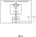
- Figure 3 shows one embodiment of a wireless device 300 in accordance with various embodiments described herein.
- the wireless device 300 includes processing circuitry 310 and communication circuitry 320.
- the communication circuitry 320 e.g., radio circuitry
- the processing circuitry 310 is configured to perform processing described above, e.g., in Figure 2 , such as by executing instructions stored in memory 330.
- the processing circuitry 310 in this regard may implement certain functional means, units, or modules.
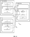
- FIG 4 shows a schematic block diagram of one embodiment of a wireless device 400 in accordance various embodiments described herein (for example, the wireless network shown in Figure 2 and Figure 10 ).
- the solution applies to any wireless device 400 having a MAC layer 410 and a PHY layer 430, including but not limited to UEs and network nodes.
- wireless device 400 implements various functional means, units, or modules (e.g., via the processing circuitry 310 in Figure 3 and/or via software code) for a MAC layer 410 and a physical layer 430.
- the MAC layer 410 of the wireless device 400 comprises a selective indication unit/circuit/module 413, a transmission delivering unit/circuit/module 415, and a determining unit/circuit/module 419, as well as an optional transmission request determining unit/circuit/module 411 and an optional receiving unit/circuit/module 417.
- the PHY layer 430 generally comprises a receiving unit/circuit/module 431, a data transmission attempting unit/circuit/module 437, and an indication unit/circuit/module 441, as well as an optional data storing unit/circuit/module 433, an optional data deleting unit/circuit/module 435, and an optional data transmission attempt determining unit/circuit/module 439.
- the transmission delivering unit/circuit/module 415 of the MAC layer 410 delivers a transmission to the PHY layer for sending to a remote wireless device, and the receiving unit/circuit/module 431 of the PHY layer receives the transmission from the MAC layer.
- the data transmission attempting unit/circuit/module 437 attempts to send the transmission to a remote wireless device.
- the indication unit/circuit/module 441 indicates to the MAC layer 410 whether the attempt to send the transmission was successful.
- the determining unit/circuit/module 419 of the MAC layer 410 determines whether an attempt to send the transmission by the PHY layer 430 was successful responsive to the indication from the PHY layer 430.
- the selective indication unit/circuit/module 413 selectively indicates to the PHY layer 430 whether to attempt to resend the transmission responsive to the determination (by the determining unit/circuit/module 419) whether the attempt to send the transmission by the PHY layer 430 was successful.
- the transmission request determining unit 411 in the MAC layer 410 determines whether to request to send the data by the PHY layer 430 during a certain TTI, while the transmission delivering unit 415 sends to the PHY layer 430 a request to send the data during the certain TTI or an indication of a cell associated with the transmission of the data during the certain TTI, and delivers to the PHY layer 430 the data to send during the certain TTI.
- the determining unit/circuit/module 419 determines whether the attempt to send the data by the PHY layer 430 was successful responsive to an indication by the PHY layer 430.
- the receiving unit 417 of the MAC layer 410 may receive an explicit indication, e.g., signaling, from the PHY layer 430 of whether the PHY layer 430 successfully sent the data during the certain TTI.
- the determining unit/circuit/module 419 may make the determination responsive to an implicit indication.
- the receiving unit/circuit/module 431 of the PHY layer 430 receives from the MAC layer 410 the data (and optionally, a request to send the data during a certain TTI or an indication of a cell associated with the transmission of the data), and a data storing unit/circuit/module 433 stores in memory the data received from the MAC layer 410.
- the data deleting unit/circuit/module 435 deletes or allows the deletion of the data stored in memory, while the data transmission attempting unit/circuit/module 437 attempts the transmission of the data during the certain TTI.
- the transmission attempt determining unit/circuit/module 439 determines whether the transmission attempt is successful or unsuccessful, and the indication unit/circuit/module 441 explicitly or implicitly indicates to the MAC layer 410 whether the PHY layer 430 successfully transmitted data that the MAC layer 410sent to the PHY layer 430 for transmission during the certain TTI.
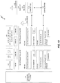
- FIG. 5A shows one exemplary general method 500 performed by the PHY layer 430 of a wireless device 400, e.g., a wireless communication device 211 or a network node 201, of communicating between a MAC layer 410 and the PHY layer 430 for sending transmissions in accordance with various embodiments described herein.
- the PHY layer 430 receives a transmission from the MAC layer 410 (block 501), and attempts to send the received transmission to a remote wireless device (block 503).
- the PHY layer 430 indicates (explicitly or implicitly) to the MAC layer 410 whether the attempt to send the transmission by the PHY layer 430 was successful (block 505).
- FIG. 5B shows a more detailed exemplary method 550 performed by the PHY layer 430.
- the PHY layer 430 receives from the MAC layer 410, a request to transmit data during a certain TTI (block 551) and an indication of a cell associated with the transmission of the data (block 553).
- the PHY layer 430 stores the received data in memory (block 555), and deletes or allows deletion, from the memory, the data responsive to the PHY layer 430 determining that the transmission attempt was successful (block 557).
- the PHY layer 430 attempts to transmit the data during the certain TTI (block 559), and determines whether the transmission attempt was successful or unsuccessful (block 561).
- the PHY layer 430 explicitly or implicitly indicates to the MAC layer 410 whether the PHY layer 430 successfully or unsuccessfully transmitted the data during the certain TTI (block 563).
- Figure 6 shows another embodiment of a method 600 performed by the PHY layer 430 of a wireless device 400, e.g., a wireless communication device 211 or a network node 201, of communicating between a MAC layer 410 and the PHY layer 430 for data transmissions in accordance with various embodiments described herein.
- method 600 of Figure 6 corresponds to block 505 of Figure 5A and/or block 563 of Figure 5B .
- the PHY layer 430 explicitly or implicitly indicates to the MAC layer 410 whether the PHY layer 430 transmitted data that the MAC layer 410 sent to the PHY layer 430 for transmission during a certain TTI (block 610).
- the PHY layer 430 in response to determining that the transmission attempt was successful, sends an indication that the transmission attempt was successful to the MAC layer 410 (block 611) or determines not to send an indication that the transmission attempt was successful to the MAC layer 410 (block 613). In another embodiment, in response to determining that the transmission attempt was unsuccessful, the PHY layer 430 sends an indication that the transmission attempt was unsuccessful to the MAC layer 410 (block 615) or determines not to send an indication that the transmission attempt was unsuccessful to the MAC layer 410 (block 617).
- the PHY layer 430 sends to the MAC layer 410 an indication of a cell associated with the transmission of the data, the receipt of which implicitly implies to the MAC layer 410 of an attempted transmission of the data by the PHY layer 430 (block 619).
- FIG. 7A shows one exemplary general method 700 performed by the MAC layer 410 of a wireless device 400, e.g., a wireless communication device 211 or a network node 201, of communicating between the MAC layer 410 and a PHY layer 430 for sending transmissions in accordance with various embodiments described herein.
- the MAC layer 410 delivers a transmission to the PHY layer 430 for sending to a remote wireless device (block 701.
- the MAC layer 410 further determines whether an attempt to send the transmission by the PHY layer 430 was successful responsive to an indication from the PHY layer 430 (block 703). Responsive to the determination of whether the an attempt to send the transmission by the PHY layer 430 was successful, the MAC layer 410 selectively indicates to the PHY layer 430 whether to attempt to resend the transmission (block 705).
- FIG. 7B shows a more detailed exemplary method 750 performed by the MAC layer 410.
- the MAC layer 410 determines whether to request to transmit data by the PHY layer 430 during a certain TTI (block 751), and sends to the PHY layer 430 a request to transmit the data during the certain TTI (block 753).
- the MAC layer 410 then delivers the data to be transmitted during the certain TTI to the PHY layer 430 (block 755).
- the MAC layer 410 may also send an indication of a cell associated with the transmission of the data during the certain TTI to the PHY layer 430 (block 757).
- the MAC layer 410 receives or determines explicit or implicit signaling by the PHY layer 430 of whether the PHY layer successful (or optionally unsuccessfully) transmitted the data during the certain TTI (block 759).
- Figure 8 shows another embodiment of a method 600 performed by the MAC layer 410 of a wireless device 400, e.g., a wireless communication device 211 or a network node 201, of communicating between the MAC layer 410 and a PHY layer 430 for data transmissions in accordance with various embodiments described herein.
- method 800 of Figure 8 corresponds to block 703 of Figure 7A and/or block 759 of Figure 7B .
- the MAC layer 410 receives or determines explicit or implicit signaling by the PHY layer 430 of whether the PHY layer 430 successfully (or unsuccessfully) transmitted the data the MAC layer 410 sent to the PHY layer 410 for transmission during the certain TTI (block 810).
- the MAC layer 410 does this by receiving, from the PHY layer 430, an indication that the transmission attempt was successful (block 811). In another embodiment, the MAC layer 410 determines that no indication was received, which implicitly indicates that the transmission attempt was unsuccessful (block 813). In another embodiment, the MAC layer 410 receives, from the PHY layer 430, an indication that the transmission attempt was unsuccessful (block 815). In another embodiment, the MAC layer 410 determines that no indication was received, which implicitly indicates that the transmission attempt was successful (block 817).
- the MAC layer 410 receives, from the PHY layer 430, an indication of a cell associated with the transmission of the data, the receipt of which implicitly signals to the MAC layer 410 an attempted transmission of the data by the PHY layer 430 (block 819).
- Figure 9 shows yet another embodiment from the perspective of a wireless device 400 having a MAC layer 410 and a PHY layer 430.
- the MAC layer 410 delivers a transmission to the PHY layer 430.
- the PHY layer 430 attempts to send the transmission to a remote wireless communication device or node.
- the PHY layer 430 indicates to the MAC layer, implicitly or explicitly, whether the attempt to send the transmission by the PHY layer was successful.
- the MAC layer 410 selectively indicates to the PHY layer 430, implicitly or explicitly, whether to attempt to resend the transmission.
- a computer program comprises instructions which, when executed on at least one processor of an apparatus, cause the apparatus to carry out any of the respective processing described above.
- a computer program in this regard may comprise one or more code modules corresponding to the means or units described above.
- Embodiments further include a carrier containing such a computer program.
- This carrier may comprise one of an electronic signal, optical signal, radio signal, or computer readable storage medium.
- embodiments herein also include a computer program product stored on a non-transitory computer readable (storage or recording) medium and comprising instructions that, when executed by a processor of an apparatus, cause the apparatus to perform as described above.
- Embodiments further include a computer program product comprising program code portions for performing the steps of any of the embodiments herein when the computer program product is executed by a computing device.
- This computer program product may be stored on a computer readable recording medium.
- Systems and methods are disclosed herein for the needed interaction between MAC layer and physical layer to handle retransmissions and associated procedures. Advantages of these systems and methods include efficient modeling of cross-layer interaction between MAC and physical layer to handle retransmissions in autonomous UL.
- the below methods address the specific case of LAA, in which a transmission attempt from a UE at PHY layer may fail because of channel busy, i.e. LBT procedure not successful. However, they can be used for any scenarios in which, for any reason, transmission of a TB at the PHY layer on a given TTI fails because of different issues, e.g. failures in the radio unit, in-device coexistence issues (to high leakage between collocated radio transceivers in the same device), interruption time due to transceiver chain switching.
- Methods for signaling LBT outcome from the MAC layer to the PHY layer include, in one embodiment, the PHY layer indicating to MAC the outcome of a transmission attempt related to the transmission of a certain transport block (TB) and/or HARQ process. If the LBT procedure is successful (channel sensed not busy) and the data are correctly transmitted over the air interface, the PHY layer sends to the MAC layer a positive acknowledge, otherwise a negative acknowledge is sent (channel sensed busy).
- TB transport block
- the PHY layer before sending a negative or positive acknowledge, keeps attempting transmission of a MAC PDU delivered by MAC, until the LBT procedure is successful.
- This method implies that the MAC PDU is stored in the PHY while the radio interface is performing LBT.
- the MAC PDU is stored in PHY until positive acknowledge is sent to MAC, upon which the PHY may delete the stored MAC PDU.
- MAC does not deliver further (re)transmissions to PHY until positive acknowledge from PHY is received (or negative acknowledge not received in time) for the MAC PDU delivered by a certain HARQ entity on a certain TTI, or until a certain maximum timer/counter (corresponding to amount of time or times for which the PHY attempted transmission of a MAC PDU) is reached, upon which PHY stops attempting transmission of this MAC PDU and MAC interprets it as negative acknowledge.
- the MAC may postpone the transmission of a MAC PDU to a later point in time and/or transmitting in another carrier.
- PHY does not explicitly signal an LBT failure. Instead, PHY treats LBT failure the same as if performing the transmission and receiving a negative ACK from the receiver that corresponds to failed decoding or missed transmission. Meaning that, upon LBT failure, the PHY generates a NACK that could have been received from the receiver and delivers it to MAC.
- PHY attempts transmitting a transport block in the same TTI in which MAC delivered the MAC PDU to the PHY and also the outcome of the LBT, upon the attempted transmission, is signaled to MAC on the same TTI.
- PHY indicates to MAC the carrier (e.g. cell index) on which it was attempted transmission, so that MAC associates the LBT outcome to the HARQ entity which is in charge of HARQ operation for the signaled carrier. Since the delivery of the MAC PDU to PHY and the report of the outcome of the LBT procedures occurs in the same TTI, the HARQ entity can associate the LBT outcome to the MAC PDU that the HARQ entity delivered to PHY in this TTI.
- the carrier e.g. cell index
- PHY attempts transmitting a transport block in a TTI, other than the TTI in which MAC delivered the MAC PDU to the PHY, or other than the outcome of the LBT, upon the attempted transmission, is signaled to MAC on another TTI.
- PHY may signal the outcome of the LBT only after a certain timer upon a successful transmission expires. This would trigger MAC to generate a MAC PDU (either new or retransmission).
- the PHY may also signal the TTI in which PHY attempted the transmission, or the TTI in which the transport block was successfully transmitted over the air interface, or the TTI in which a retransmission for this transport block should occur.
- the HARQ entity associated to this carrier may then retrieve the HARQ process which delivered to PHY the MAC PDU from the reported TTI.
- Some of the above actions may be instead taken by PHY, only when a transmission is really generated/performed over the air interface.
- the PHY may trigger a timer when it manages to transmit a transport block over the air interface, and when this timer expires PHY tells MAC that another (re)transmission for a certain HARQ process (which can be retrieved following methods disclosed in Section 0) is allowed to be triggered, e.g. in the same TTI in which PHY signals to MAC that the timer has expired or at a later point in time.
- a plurality of actions may be taken by the MAC layer and PHY.
- a wireless network such as the example wireless network illustrated in Figure 10 .
- the wireless network of Figure 10 only depicts network 906, network nodes 960 and 960b, and WDs 910, 910b, and 910c.
- a wireless network may further include any additional elements suitable to support communication between wireless devices or between a wireless device and another communication device, such as a landline telephone, a service provider, or any other network node or end device.
- network node 960 and wireless device (WD) 910 are depicted with additional detail.
- the wireless network may provide communication and other types of services to one or more wireless devices to facilitate the wireless devices' access to and/or use of the services provided by, or via, the wireless network.
- the wireless network may comprise and/or interface with any type of communication, telecommunication, data, cellular, and/or radio network or other similar type of system.
- the wireless network may be configured to operate according to specific standards or other types of predefined rules or procedures.
- particular embodiments of the wireless network may implement communication standards, such as Global System for Mobile Communications (GSM), Universal Mobile Telecommunications System (UMTS), Long Term Evolution (LTE), Narrowband Internet of Things (NB-IoT), and/or other suitable 2G, 3G, 4G, or 5G standards; wireless local area network (WLAN) standards, such as the IEEE 802.11 standards; and/or any other appropriate wireless communication standard, such as the Worldwide Interoperability for Microwave Access (WiMax), Bluetooth, Z-Wave and/or ZigBee standards.
- GSM Global System for Mobile Communications
- UMTS Universal Mobile Telecommunications System
- LTE Long Term Evolution
- NB-IoT Narrowband Internet of Things
- WLAN wireless local area network
- WiMax Worldwide Interoper
- Network 906 may comprise one or more backhaul networks, core networks, IP networks, public switched telephone networks (PSTNs), packet data networks, optical networks, wide-area networks (WANs), local area networks (LANs), wireless local area networks (WLANs), wired networks, wireless networks, metropolitan area networks, and other networks to enable communication between devices.
- PSTNs public switched telephone networks
- WANs wide-area networks
- LANs local area networks
- WLANs wireless local area networks
- wired networks wireless networks, metropolitan area networks, and other networks to enable communication between devices.
- Network node 960 and WD 910 comprise various components described in more detail below. These components work together in order to provide network node and/or wireless device functionality, such as providing wireless connections in a wireless network.
- the wireless network may comprise any number of wired or wireless networks, network nodes, base stations, controllers, wireless devices, relay stations, and/or any other components or systems that may facilitate or participate in the communication of data and/or signals whether via wired or wireless connections.
- network node refers to equipment capable, configured, arranged and/or operable to communicate directly or indirectly with a wireless device and/or with other network nodes or equipment in the wireless network to enable and/or provide wireless access to the wireless device and/or to perform other functions (e.g., administration) in the wireless network.
- network nodes include, but are not limited to, access points (APs) (e.g., radio access points), base stations (BSs) (e.g., radio base stations, Node Bs, evolved Node Bs (eNBs) and NR NodeBs (gNBs)), etc.
- APs access points
- BSs base stations
- eNBs evolved Node Bs
- gNBs NR NodeBs
- Base stations may be categorized based on the amount of coverage they provide (or, stated differently, their transmit power level) and may then also be referred to as femto base stations, pico base stations, micro base stations, or macro base stations.
- a base station may be a relay node or a relay donor node controlling a relay.
- a network node may also include one or more (or all) parts of a distributed radio base station such as centralized digital units and/or remote radio units (RRUs), sometimes referred to as Remote Radio Heads (RRHs). Such remote radio units may or may not be integrated with an antenna as an antenna integrated radio.
- RRUs remote radio units
- RRHs Remote Radio Heads
- Such remote radio units may or may not be integrated with an antenna as an antenna integrated radio.
- Parts of a distributed radio base station may also be referred to as nodes in a distributed antenna system (DAS).
- DAS distributed antenna system
- network nodes include multi-standard radio (MSR) equipment such as MSR BSs, network controllers such as radio network controllers (RNCs) or base station controllers (BSCs), base transceiver stations (BTSs), transmission points, transmission nodes, multi-cell/multicast coordination entities (MCEs), core network nodes (e.g., MSCs, MMEs), O&M nodes, OSS nodes, SON nodes, positioning nodes (e.g., E-SMLCs), and/or MDTs.
- MSR multi-standard radio
- RNCs radio network controllers
- BSCs base station controllers
- BTSs base transceiver stations
- transmission points transmission nodes
- MCEs multi-cell/multicast coordination entities
- core network nodes e.g., MSCs, MMEs
- O&M nodes e.g., OSS nodes, SON nodes, positioning nodes (e.g., E-SMLCs), and/or MDTs.
- network nodes may represent any suitable device (or group of devices) capable, configured, arranged, and/or operable to enable and/or provide a wireless device with access to the wireless network or to provide some service to a wireless device that has accessed the wireless network.
- network node 960 includes processing circuitry 970, device readable medium 980, interface 990, auxiliary equipment 984, power source 986, power circuitry 987, and antenna 962.
- network node 960 illustrated in the example wireless network of Figure 10 may represent a device that includes the illustrated combination of hardware components, other embodiments may comprise network nodes with different combinations of components. It is to be understood that a network node comprises any suitable combination of hardware and/or software needed to perform the tasks, features, functions and methods disclosed herein.
- network node 960 may comprise multiple different physical components that make up a single illustrated component (e.g., device readable medium 980 may comprise multiple separate hard drives as well as multiple RAM modules).
- network node 960 may be composed of multiple physically separate components (e.g., a NodeB component and a RNC component, or a BTS component and a BSC component, etc.), which may each have their own respective components.
- network node 960 comprises multiple separate components (e.g., BTS and BSC components)
- one or more of the separate components may be shared among several network nodes.
- a single RNC may control multiple NodeB's.
- each unique NodeB and RNC pair may in some instances be considered a single separate network node.
- network node 960 may be configured to support multiple radio access technologies (RATs).
- RATs radio access technologies
- Network node 960 may also include multiple sets of the various illustrated components for different wireless technologies integrated into network node 960, such as, for example, GSM, WCDMA, LTE, NR, WiFi, or Bluetooth wireless technologies. These wireless technologies may be integrated into the same or different chip or set of chips and other components within network node 960.
- Processing circuitry 970 is configured to perform any determining, calculating, or similar operations (e.g., certain obtaining operations) described herein as being provided by a network node. These operations performed by processing circuitry 970 may include processing information obtained by processing circuitry 970 by, for example, converting the obtained information into other information, comparing the obtained information or converted information to information stored in the network node, and/or performing one or more operations based on the obtained information or converted information, and as a result of said processing making a determination.
- processing information obtained by processing circuitry 970 by, for example, converting the obtained information into other information, comparing the obtained information or converted information to information stored in the network node, and/or performing one or more operations based on the obtained information or converted information, and as a result of said processing making a determination.
- Processing circuitry 970 may comprise a combination of one or more of a microprocessor, controller, microcontroller, central processing unit, digital signal processor, application-specific integrated circuit, field programmable gate array, or any other suitable computing device, resource, or combination of hardware, software and/or encoded logic operable to provide, either alone or in conjunction with other network node 960 components, such as device readable medium 980, network node 960 functionality.
- processing circuitry 970 may execute instructions stored in device readable medium 980 or in memory within processing circuitry 970. Such functionality may include providing any of the various wireless features, functions, or benefits discussed herein.
- processing circuitry 970 may include a system on a chip (SOC).
- SOC system on a chip
- processing circuitry 970 may include one or more of radio frequency (RF) transceiver circuitry 972 and baseband processing circuitry 974.
- radio frequency (RF) transceiver circuitry 972 and baseband processing circuitry 974 may be on separate chips (or sets of chips), boards, or units, such as radio units and digital units.
- part or all of RF transceiver circuitry 972 and baseband processing circuitry 974 may be on the same chip or set of chips, boards, or units
- processing circuitry 970 executing instructions stored on device readable medium 980 or memory within processing circuitry 970.
- some or all of the functionality may be provided by processing circuitry 970 without executing instructions stored on a separate or discrete device readable medium, such as in a hard-wired manner.
- processing circuitry 970 can be configured to perform the described functionality. The benefits provided by such functionality are not limited to processing circuitry 970 alone or to other components of network node 960, but are enjoyed by network node 960 as a whole, and/or by end users and the wireless network generally.
- Device readable medium 980 may comprise any form of volatile or non-volatile computer readable memory including, without limitation, persistent storage, solid-state memory, remotely mounted memory, magnetic media, optical media, random access memory (RAM), read-only memory (ROM), mass storage media (for example, a hard disk), removable storage media (for example, a flash drive, a Compact Disk (CD) or a Digital Video Disk (DVD)), and/or any other volatile or non-volatile, non-transitory device readable and/or computer-executable memory devices that store information, data, and/or instructions that may be used by processing circuitry 970.
- volatile or non-volatile computer readable memory including, without limitation, persistent storage, solid-state memory, remotely mounted memory, magnetic media, optical media, random access memory (RAM), read-only memory (ROM), mass storage media (for example, a hard disk), removable storage media (for example, a flash drive, a Compact Disk (CD) or a Digital Video Disk (DVD)), and/or any other volatile or
- Device readable medium 980 may store any suitable instructions, data or information, including a computer program, software, an application including one or more of logic, rules, code, tables, etc. and/or other instructions capable of being executed by processing circuitry 970 and, utilized by network node 960.
- Device readable medium 980 may be used to store any calculations made by processing circuitry 970 and/or any data received via interface 990.
- processing circuitry 970 and device readable medium 980 may be considered to be integrated.
- Interface 990 is used in the wired or wireless communication of signaling and/or data between network node 960, network 906, and/or WDs 910. As illustrated, interface 990 comprises port(s)/terminal(s) 994 to send and receive data, for example to and from network 906 over a wired connection. Interface 990 also includes radio front end circuitry 992 that may be coupled to, or in certain embodiments a part of, antenna 962. Radio front end circuitry 992 comprises filters 998 and amplifiers 996. Radio front end circuitry 992 may be connected to antenna 962 and processing circuitry 970. Radio front end circuitry may be configured to condition signals communicated between antenna 962 and processing circuitry 970.
- Radio front end circuitry 992 may receive digital data that is to be sent out to other network nodes or WDs via a wireless connection. Radio front end circuitry 992 may convert the digital data into a radio signal having the appropriate channel and bandwidth parameters using a combination of filters 998 and/or amplifiers 996. The radio signal may then be transmitted via antenna 962. Similarly, when receiving data, antenna 962 may collect radio signals which are then converted into digital data by radio front end circuitry 992. The digital data may be passed to processing circuitry 970. In other embodiments, the interface may comprise different components and/or different combinations of components.
- network node 960 may not include separate radio front end circuitry 992, instead, processing circuitry 970 may comprise radio front end circuitry and may be connected to antenna 962 without separate radio front end circuitry 992. Similarly, in some embodiments, all or some of RF transceiver circuitry 972 may be considered a part of interface 990. In still other embodiments, interface 990 may include one or more ports or terminals 994, radio front end circuitry 992, and RF transceiver circuitry 972, as part of a radio unit (not shown), and interface 990 may communicate with baseband processing circuitry 974, which is part of a digital unit (not shown).
- Antenna 962 may include one or more antennas, or antenna arrays, configured to send and/or receive wireless signals. Antenna 962 may be coupled to radio front end circuitry 990 and may be any type of antenna capable of transmitting and receiving data and/or signals wirelessly. In some embodiments, antenna 962 may comprise one or more omni-directional, sector or panel antennas operable to transmit/receive radio signals between, for example, 2 GHz and 66 GHz. An omni-directional antenna may be used to transmit/receive radio signals in any direction, a sector antenna may be used to transmit/receive radio signals from devices within a particular area, and a panel antenna may be a line of sight antenna used to transmit/receive radio signals in a relatively straight line. In some instances, the use of more than one antenna may be referred to as MIMO. In certain embodiments, antenna 962 may be separate from network node 960 and may be connectable to network node 960 through an interface or port.
- Antenna 962, interface 990, and/or processing circuitry 970 may be configured to perform any receiving operations and/or certain obtaining operations described herein as being performed by a network node. Any information, data and/or signals may be received from a wireless device, another network node and/or any other network equipment. Similarly, antenna 962, interface 990, and/or processing circuitry 970 may be configured to perform any transmitting operations described herein as being performed by a network node. Any information, data and/or signals may be transmitted to a wireless device, another network node and/or any other network equipment.
- Power circuitry 987 may comprise, or be coupled to, power management circuitry and is configured to supply the components of network node 960 with power for performing the functionality described herein. Power circuitry 987 may receive power from power source 986. Power source 986 and/or power circuitry 987 may be configured to provide power to the various components of network node 960 in a form suitable for the respective components (e.g., at a voltage and current level needed for each respective component). Power source 986 may either be included in, or external to, power circuitry 987 and/or network node 960.
- network node 960 may be connectable to an external power source (e.g., an electricity outlet) via an input circuitry or interface such as an electrical cable, whereby the external power source supplies power to power circuitry 987.
- power source 986 may comprise a source of power in the form of a battery or battery pack which is connected to, or integrated in, power circuitry 987. The battery may provide backup power should the external power source fail.
- Other types of power sources such as photovoltaic devices, may also be used.
- network node 960 may include additional components beyond those shown in Figure 10 that may be responsible for providing certain aspects of the network node's functionality, including any of the functionality described herein and/or any functionality necessary to support the subject matter described herein.
- network node 960 may include user interface equipment to allow input of information into network node 960 and to allow output of information from network node 960. This may allow a user to perform diagnostic, maintenance, repair, and other administrative functions for network node 960.
- wireless device refers to a device capable, configured, arranged and/or operable to communicate wirelessly with network nodes and/or other wireless devices.
- the term WD may be used interchangeably herein with user equipment (UE).
- Communicating wirelessly may involve transmitting and/or receiving wireless signals using electromagnetic waves, radio waves, infrared waves, and/or other types of signals suitable for conveying information through air.
- a WD may be configured to transmit and/or receive information without direct human interaction.
- a WD may be designed to transmit information to a network on a predetermined schedule, when triggered by an internal or external event, or in response to requests from the network.
- Examples of a WD include, but are not limited to, a smart phone, a mobile phone, a cell phone, a voice over IP (VoIP) phone, a wireless local loop phone, a desktop computer, a personal digital assistant (PDA), a wireless cameras, a gaming console or device, a music storage device, a playback appliance, a wearable terminal device, a wireless endpoint, a mobile station, a tablet, a laptop, a laptop-embedded equipment (LEE), a laptop-mounted equipment (LME), a smart device, a wireless customer-premise equipment (CPE). a vehicle-mounted wireless terminal device, etc.
- a WD may support device-to-device (D2D) communication, for example by implementing a 3GPP standard for sidelink communication, vehicle-to-vehicle (V2V), vehicle-to-infrastructure (V2I), vehicle-to-everything (V2X) and may in this case be referred to as a D2D communication device.
- D2D device-to-device
- V2V vehicle-to-vehicle
- V2I vehicle-to-infrastructure
- V2X vehicle-to-everything
- a WD may represent a machine or other device that performs monitoring and/or measurements, and transmits the results of such monitoring and/or measurements to another WD and/or a network node.
- the WD may in this case be a machine-to-machine (M2M) device, which may in a 3GPP context be referred to as an MTC device.
- M2M machine-to-machine
- the WD may be a UE implementing the 3GPP narrow band internet of things (NB-IoT) standard.
- NB-IoT narrow band internet of things
- machines or devices are sensors, metering devices such as power meters, industrial machinery, or home or personal appliances (e.g. refrigerators, televisions, etc.) personal wearables (e.g., watches, fitness trackers, etc.).
- a WD may represent a vehicle or other equipment that is capable of monitoring and/or reporting on its operational status or other functions associated with its operation.
- a WD as described above may represent the endpoint of a wireless connection, in which case the device may be referred to as a wireless terminal. Furthermore, a WD as described above may be mobile, in which case it may also be referred to as a mobile device or a mobile terminal.
- wireless device 910 includes antenna 911, interface 914, processing circuitry 920, device readable medium 930, user interface equipment 932, auxiliary equipment 934, power source 936 and power circuitry 937.
- WD 910 may include multiple sets of one or more of the illustrated components for different wireless technologies supported by WD 910, such as, for example, GSM, WCDMA, LTE, NR, WiFi, WiMAX, NB-IoT, or Bluetooth wireless technologies, just to mention a few. These wireless technologies may be integrated into the same or different chips or set of chips as other components within WD 910.
- Antenna 911 is connected to interface 914, and may include one or more antennas, or antenna arrays, configured to send and/or receive wireless signals.
- antenna 911 may be separate from WD 910 and be connectable to WD 910 through an interface or port.
- Antenna 911, interface 914, and/or processing circuitry 920 may be configured to perform any receiving or transmitting operations described herein as being performed by a WD. Any information, data and/or signals may be received from a network node and/or another WD.
- radio front end circuitry and/or antenna 911 may be considered an interface.
- interface 914 comprises radio front end circuitry 912 and antenna 911.
- Radio front end circuitry 912 comprises one or more filters 918 and amplifiers 99.
- Radio front end circuitry 914 is connected to antenna 911 and processing circuitry 920, and is configured to condition signals communicated between antenna 911 and processing circuitry 920.
- Radio front end circuitry 912 may be coupled to or a part of antenna 911.
- WD 910 may not include separate radio front end circuitry 912; rather, processing circuitry 920 may comprise radio front end circuitry and may be connected to antenna 911.
- some or all of RF transceiver circuitry 922 may be considered a part of interface 914.
- Radio front end circuitry 912 may receive digital data that is to be sent out to other network nodes or WDs via a wireless connection. Radio front end circuitry 912 may convert the digital data into a radio signal having the appropriate channel and bandwidth parameters using a combination of filters 918 and/or amplifiers 996. The radio signal may then be transmitted via antenna 911. Similarly, when receiving data, antenna 911 may collect radio signals which are then converted into digital data by radio front end circuitry 912. The digital data may be passed to processing circuitry 920. In other embodiments, the interface may comprise different components and/or different combinations of components.
- Processing circuitry 920 may comprise a combination of one or more of a microprocessor, controller, microcontroller, central processing unit, digital signal processor, application-specific integrated circuit, field programmable gate array, or any other suitable computing device, resource, or combination of hardware, software, and/or encoded logic operable to provide, either alone or in conjunction with other WD 910 components, such as device readable medium 930, WD 910 functionality. Such functionality may include providing any of the various wireless features or benefits discussed herein. For example, processing circuitry 920 may execute instructions stored in device readable medium 930 or in memory within processing circuitry 920 to provide the functionality disclosed herein.
- processing circuitry 920 includes one or more of RF transceiver circuitry 922, baseband processing circuitry 924, and application processing circuitry 926.
- the processing circuitry may comprise different components and/or different combinations of components.
- processing circuitry 920 of WD 910 may comprise a SOC.
- RF transceiver circuitry 922, baseband processing circuitry 924, and application processing circuitry 926 may be on separate chips or sets of chips.
- part or all of baseband processing circuitry 924 and application processing circuitry 926 may be combined into one chip or set of chips, and RF transceiver circuitry 922 may be on a separate chip or set of chips.
- part or all of RF transceiver circuitry 922 and baseband processing circuitry 924 may be on the same chip or set of chips, and application processing circuitry 926 may be on a separate chip or set of chips.
- part or all of RF transceiver circuitry 922, baseband processing circuitry 924, and application processing circuitry 926 may be combined in the same chip or set of chips.
- RF transceiver circuitry 922 may be a part of interface 914.
- RF transceiver circuitry 922 may condition RF signals for processing circuitry 920.
- processing circuitry 920 executing instructions stored on device readable medium 930, which in certain embodiments may be a computer-readable storage medium.
- some or all of the functionality may be provided by processing circuitry 920 without executing instructions stored on a separate or discrete device readable storage medium, such as in a hard-wired manner.
- processing circuitry 920 can be configured to perform the described functionality. The benefits provided by such functionality are not limited to processing circuitry 920 alone or to other components of WD 910, but are enjoyed by WD 910 as a whole, and/or by end users and the wireless network generally.
- Processing circuitry 920 may be configured to perform any determining, calculating, or similar operations (e.g., certain obtaining operations) described herein as being performed by a WD. These operations, as performed by processing circuitry 920, may include processing information obtained by processing circuitry 920 by, for example, converting the obtained information into other information, comparing the obtained information or converted information to information stored by WD 910, and/or performing one or more operations based on the obtained information or converted information, and as a result of said processing making a determination.
- processing information obtained by processing circuitry 920 by, for example, converting the obtained information into other information, comparing the obtained information or converted information to information stored by WD 910, and/or performing one or more operations based on the obtained information or converted information, and as a result of said processing making a determination.
- Device readable medium 930 may be operable to store a computer program, software, an application including one or more of logic, rules, code, tables, etc. and/or other instructions capable of being executed by processing circuitry 920.
- Device readable medium 930 may include computer memory (e.g., Random Access Memory (RAM) or Read Only Memory (ROM)), mass storage media (e.g., a hard disk), removable storage media (e.g., a Compact Disk (CD) or a Digital Video Disk (DVD)), and/or any other volatile or non-volatile, non-transitory device readable and/or computer executable memory devices that store information, data, and/or instructions that may be used by processing circuitry 920.
- processing circuitry 920 and device readable medium 930 may be considered to be integrated.
- User interface equipment 932 may provide components that allow for a human user to interact with WD 910. Such interaction may be of many forms, such as visual, audial, tactile, etc. User interface equipment 932 may be operable to produce output to the user and to allow the user to provide input to WD 910. The type of interaction may vary depending on the type of user interface equipment 932 installed in WD 910. For example, if WD 910 is a smart phone, the interaction may be via a touch screen; if WD 910 is a smart meter, the interaction may be through a screen that provides usage (e.g., the number of gallons used) or a speaker that provides an audible alert (e.g., if smoke is detected).
- usage e.g., the number of gallons used
- a speaker that provides an audible alert
- User interface equipment 932 may include input interfaces, devices and circuits, and output interfaces, devices and circuits. User interface equipment 932 is configured to allow input of information into WD 910, and is connected to processing circuitry 920 to allow processing circuitry 920 to process the input information. User interface equipment 932 may include, for example, a microphone, a proximity or other sensor, keys/buttons, a touch display, one or more cameras, a USB port, or other input circuitry. User interface equipment 932 is also configured to allow output of information from WD 910, and to allow processing circuitry 920 to output information from WD 910. User interface equipment 932 may include, for example, a speaker, a display, vibrating circuitry, a USB port, a headphone interface, or other output circuitry. Using one or more input and output interfaces, devices, and circuits, of user interface equipment 932, WD 910 may communicate with end users and/or the wireless network, and allow them to benefit from the functionality described herein.
- Auxiliary equipment 934 is operable to provide more specific functionality which may not be generally performed by WDs. This may comprise specialized sensors for doing measurements for various purposes, interfaces for additional types of communication such as wired communications etc. The inclusion and type of components of auxiliary equipment 934 may vary depending on the embodiment and/or scenario.
- Power source 936 may, in some embodiments, be in the form of a battery or battery pack. Other types of power sources, such as an external power source (e.g., an electricity outlet), photovoltaic devices or power cells, may also be used.
- WD 910 may further comprise power circuitry 937 for delivering power from power source 936 to the various parts of WD 910 which need power from power source 936 to carry out any functionality described or indicated herein.
- Power circuitry 937 may in certain embodiments comprise power management circuitry.
- Power circuitry 937 may additionally or alternatively be operable to receive power from an external power source; in which case WD 910 may be connectable to the external power source (such as an electricity outlet) via input circuitry or an interface such as an electrical power cable.
- Power circuitry 937 may also in certain embodiments be operable to deliver power from an external power source to power source 936. This may be, for example, for the charging of power source 936. Power circuitry 937 may perform any formatting, converting, or other modification to the power from power source 936 to make the power suitable for the respective components of WD 910 to which power is supplied.
- Figure 11 illustrates one embodiment of a UE in accordance with various aspects described herein.
- a user equipment or UE may not necessarily have a user in the sense of a human user who owns and/or operates the relevant device.
- a UE may represent a device that is intended for sale to, or operation by, a human user but which may not, or which may not initially, be associated with a specific human user (e.g., a smart sprinkler controller).
- a UE may represent a device that is not intended for sale to, or operation by, an end user but which may be associated with or operated for the benefit of a user (e.g., a smart power meter).
- UE 1020 may be any UE identified by the 3rd Generation Partnership Project (3GPP), including a NB-loT UE, a machine type communication (MTC) UE, and/or an enhanced MTC (eMTC) UE.
- UE 1000 as illustrated in Figure 11 , is one example of a WD configured for communication in accordance with one or more communication standards promulgated by the 3rd Generation Partnership Project (3GPP), such as 3GPP's GSM, UMTS, LTE, and/or 5G standards.
- 3GPP 3rd Generation Partnership Project
- GSM Global System for Mobile communications
- UMTS Universal Mobile communications
- LTE Long Term Evolution
- 5G 5G
- the term WD and UE may be used interchangeable. Accordingly, although Figure 11 is a UE, the components discussed herein are equally applicable to a WD, and vice-versa.
- UE 1000 includes processing circuitry 1001 that is operatively coupled to input/output interface 1005, radio frequency (RF) interface 1009, network connection interface 1011, memory 1015 including random access memory (RAM) 1010, read-only memory (ROM) 1019, and storage medium 1021 or the like, communication subsystem 1031, power source 1033, and/or any other component, or any combination thereof.
- Storage medium 1021 includes operating system 1023, application program 1025, and data 1027. In other embodiments, storage medium 1021 may include other similar types of information.
- Certain UEs may utilize all of the components shown in Figure 11 , or only a subset of the components. The level of integration between the components may vary from one UE to another UE. Further, certain UEs may contain multiple instances of a component, such as multiple processors, memories, transceivers, transmitters, receivers, etc.
- processing circuitry 1001 may be configured to process computer instructions and data.
- Processing circuitry 1001 may be configured to implement any sequential state machine operative to execute machine instructions stored as machine-readable computer programs in the memory, such as one or more hardware-implemented state machines (e.g., in discrete logic, FPGA, ASIC, etc.); programmable logic together with appropriate firmware; one or more stored program, general-purpose processors, such as a microprocessor or Digital Signal Processor (DSP), together with appropriate software; or any combination of the above.
- the processing circuitry 1001 may include two central processing units (CPUs). Data may be information in a form suitable for use by a computer.
- input/output interface 1005 may be configured to provide a communication interface to an input device, output device, or input and output device.
- UE 1000 may be configured to use an output device via input/output interface 1005.
- An output device may use the same type of interface port as an input device.
- a USB port may be used to provide input to and output from UE 1000.
- the output device may be a speaker, a sound card, a video card, a display, a monitor, a printer, an actuator, an emitter, a smartcard, another output device, or any combination thereof.
- UE 1000 may be configured to use an input device via input/output interface 1005 to allow a user to capture information into UE 1000.
- the input device may include a touch-sensitive or presence-sensitive display, a camera (e.g., a digital camera, a digital video camera, a web camera, etc.), a microphone, a sensor, a mouse, a trackball, a directional pad, a trackpad, a scroll wheel, a smartcard, and the like.
- the presence-sensitive display may include a capacitive or resistive touch sensor to sense input from a user.
- a sensor may be, for instance, an accelerometer, a gyroscope, a tilt sensor, a force sensor, a magnetometer, an optical sensor, a proximity sensor, another like sensor, or any combination thereof.
- the input device may be an accelerometer, a magnetometer, a digital camera, a microphone, and an optical sensor.
- RF interface 1009 may be configured to provide a communication interface to RF components such as a transmitter, a receiver, and an antenna.
- Network connection interface 1011 may be configured to provide a communication interface to network 1043a.
- Network 1043a may encompass wired and/or wireless networks such as a local-area network (LAN), a wide-area network (WAN), a computer network, a wireless network, a telecommunications network, another like network or any combination thereof.
- network 1043a may comprise a Wi-Fi network.
- Network connection interface 1011 may be configured to include a receiver and a transmitter interface used to communicate with one or more other devices over a communication network according to one or more communication protocols, such as Ethernet, TCP/IP, SONET, ATM, or the like.
- Network connection interface 1011 may implement receiver and transmitter functionality appropriate to the communication network links (e.g., optical, electrical, and the like). The transmitter and receiver functions may share circuit components, software or firmware, or alternatively may be implemented separately.
- RAM 1010 may be configured to interface via bus 1002 to processing circuitry 1001 to provide storage or caching of data or computer instructions during the execution of software programs such as the operating system, application programs, and device drivers.
- ROM 1019 may be configured to provide computer instructions or data to processing circuitry 1001.
- ROM 1019 may be configured to store invariant low-level system code or data for basic system functions such as basic input and output (I/O), startup, or reception of keystrokes from a keyboard that are stored in a non-volatile memory.
- Storage medium 1021 may be configured to include memory such as RAM, ROM, programmable read-only memory (PROM), erasable programmable read-only memory (EPROM), electrically erasable programmable read-only memory (EEPROM), magnetic disks, optical disks, floppy disks, hard disks, removable cartridges, or flash drives.
- storage medium 1021 may be configured to include operating system 1023, application program 1025 such as a web browser application, a widget or gadget engine or another application, and data file 1027.
- Storage medium 1021 may store, for use by UE 1000, any of a variety of various operating systems or combinations of operating systems.
- Storage medium 1021 may be configured to include a number of physical drive units, such as redundant array of independent disks (RAID), floppy disk drive, flash memory, USB flash drive, external hard disk drive, thumb drive, pen drive, key drive, high-density digital versatile disc (HD-DVD) optical disc drive, internal hard disk drive, Blu-Ray optical disc drive, holographic digital data storage (HDDS) optical disc drive, external mini-dual in-line memory module (DIMM), synchronous dynamic random access memory (SDRAM), external micro-DIMM SDRAM, smartcard memory such as a subscriber identity module or a removable user identity (SIM/RUIM) module, other memory, or any combination thereof.
- RAID redundant array of independent disks
- HD-DVD high-density digital versatile disc
- HDDS holographic digital data storage
- DIMM external mini-dual in-line memory module
- SDRAM synchronous dynamic random access memory
- SDRAM synchronous dynamic random access memory
- smartcard memory such as a subscriber identity module or a removable user
- Storage medium 1021 may allow UE 1000 to access computer-executable instructions, application programs or the like, stored on transitory or non-transitory memory media, to off-load data, or to upload data.
- An article of manufacture, such as one utilizing a communication system may be tangibly embodied in storage medium 1021, which may comprise a device readable medium.
- processing circuitry 1001 may be configured to communicate with network 1043b using communication subsystem 1031.
- Network 1043a and network 1043b may be the same network or networks or different network or networks.
- Communication subsystem 1031 may be configured to include one or more transceivers used to communicate with network 1043b.
- communication subsystem 1031 may be configured to include one or more transceivers used to communicate with one or more remote transceivers of another device capable of wireless communication such as another WD, UE, or base station of a radio access network (RAN) according to one or more communication protocols, such as IEEE 802.12, CDMA, WCDMA, GSM, LTE, UTRAN, WiMax, or the like.
- RAN radio access network
- Each transceiver may include transmitter 1033 and/or receiver 1035 to implement transmitter or receiver functionality, respectively, appropriate to the RAN links (e.g., frequency allocations and the like). Further, transmitter 1033 and receiver 1035 of each transceiver may share circuit components, software or firmware, or alternatively may be implemented separately.
- the communication functions of communication subsystem 1031 may include data communication, voice communication, multimedia communication, short-range communications such as Bluetooth, near-field communication, location-based communication such as the use of the global positioning system (GPS) to determine a location, another like communication function, or any combination thereof.
- communication subsystem 1031 may include cellular communication, Wi-Fi communication, Bluetooth communication, and GPS communication.
- Network 1043b may encompass wired and/or wireless networks such as a local-area network (LAN), a wide-area network (WAN), a computer network, a wireless network, a telecommunications network, another like network or any combination thereof.
- network 1043b may be a cellular network, a Wi-Fi network, and/or a near-field network.
- Power source 1013 may be configured to provide alternating current (AC) or direct current (DC) power to components of UE 1000.
- communication subsystem 1031 may be configured to include any of the components described herein.
- processing circuitry 1001 may be configured to communicate with any of such components over bus 1002.
- any of such components may be represented by program instructions stored in memory that when executed by processing circuitry 1001 perform the corresponding functions described herein.
- the functionality of any of such components may be partitioned between processing circuitry 1001 and communication subsystem 1031.
- the non-computationally intensive functions of any of such components may be implemented in software or firmware and the computationally intensive functions may be implemented in hardware.
- FIG 12 is a schematic block diagram illustrating a virtualization environment 1100 in which functions implemented by some embodiments may be virtualized.
- virtualizing means creating virtual versions of apparatuses or devices, which may include virtualizing hardware platforms, storage devices, and networking resources.
- virtualization can be applied to a node (e.g., a virtualized base station or a virtualized radio access node) or to a device (e.g., a UE, a wireless device or any other type of communication device) or components thereof and relates to an implementation in which at least a portion of the functionality is implemented as one or more virtual components (e.g., via one or more applications, components, functions, virtual machines or containers executing on one or more physical processing nodes in one or more networks).
- a node e.g., a virtualized base station or a virtualized radio access node
- a device e.g., a UE, a wireless device or any other type of communication device
- some or all of the functions described herein may be implemented as virtual components executed by one or more virtual machines implemented in one or more virtual environments 1100 hosted by one or more of hardware nodes 1130. Further, in embodiments in which the virtual node is not a radio access node or does not require radio connectivity (e.g., a core network node), then the network node may be entirely virtualized.
- the functions may be implemented by one or more applications 1120 (which may alternatively be called software instances, virtual appliances, network functions, virtual nodes, virtual network functions, etc.) operative to implement some of the features, functions, and/or benefits of some of the embodiments disclosed herein.
- Applications 1120 are run in virtualization environment 1100 which provides hardware 1130 comprising processing circuitry 1160 and memory 1190.
- Memory 1190 contains instructions 1195 executable by processing circuitry 1160 whereby application 1120 is operative to provide one or more of the features, benefits, and/or functions disclosed herein.
- Virtualization environment 1100 comprises general-purpose or special-purpose network hardware devices 1130 comprising a set of one or more processors or processing circuitry 1160, which may be commercial off-the-shelf (COTS) processors, dedicated Application Specific Integrated Circuits (ASICs), or any other type of processing circuitry including digital or analog hardware components or special purpose processors.
- processors or processing circuitry 1160 which may be commercial off-the-shelf (COTS) processors, dedicated Application Specific Integrated Circuits (ASICs), or any other type of processing circuitry including digital or analog hardware components or special purpose processors.
- Each hardware device may comprise memory 1190-1 which may be non-persistent memory for temporarily storing instructions 1195 or software executed by processing circuitry 1160.
- Each hardware device may comprise one or more network interface controllers (NICs) 1170, also known as network interface cards, which include physical network interface 1180.
- NICs network interface controllers
- Each hardware device may also include non-transitory, persistent, machine-readable storage media 1190-2 having stored therein software 1195 and/or instructions executable by processing circuitry 1160.
- Software 1195 may include any type of software including software for instantiating one or more virtualization layers 1150 (also referred to as hypervisors), software to execute virtual machines 1140 as well as software allowing it to execute functions, features and/or benefits described in relation with some embodiments described herein.
- Virtual machines 1140 comprise virtual processing, virtual memory, virtual networking or interface and virtual storage, and may be run by a corresponding virtualization layer 1150 or hypervisor. Different embodiments of the instance of virtual appliance 1120 may be implemented on one or more of virtual machines 1140, and the implementations may be made in different ways.
- processing circuitry 1160 executes software 1195 to instantiate the hypervisor or virtualization layer 1150, which may sometimes be referred to as a virtual machine monitor (VMM).
- VMM virtual machine monitor
- Virtualization layer 1150 may present a virtual operating platform that appears like networking hardware to virtual machine 1140.
- hardware 1130 may be a standalone network node with generic or specific components. Hardware 1130 may comprise antenna 11225 and may implement some functions via virtualization. Alternatively, hardware 1130 may be part of a larger cluster of hardware (e.g. such as in a data center or customer premise equipment (CPE)) where many hardware nodes work together and are managed via management and orchestration (MANO) 1110, which, among others, oversees lifecycle management of applications 1120.
- CPE customer premise equipment
- MANO management and orchestration
- NFV network function virtualization
- NFV may be used to consolidate many network equipment types onto industry standard high volume server hardware, physical switches, and physical storage, which can be located in data centers, and customer premise equipment.
- virtual machine 1140 may be a software implementation of a physical machine that runs programs as if they were executing on a physical, non-virtualized machine.
- Each of virtual machines 1140, and that part of hardware 1130 that executes that virtual machine be it hardware dedicated to that virtual machine and/or hardware shared by that virtual machine with others of the virtual machines 1140, forms a separate virtual network elements (VNE).
- VNE virtual network elements
- VNF Virtual Network Function
- one or more radio units 1120 that each include one or more transmitters 1122 and one or more receivers 1121 may be coupled to one or more antennas 1125.
- Radio units 1120 may communicate directly with hardware nodes 1130 via one or more appropriate network interfaces and may be used in combination with the virtual components to provide a virtual node with radio capabilities, such as a radio access node or a base station.
- control system 1123 which may alternatively be used for communication between the hardware nodes 1130 and radio units 1120.
- a communication system includes telecommunication network 1210, such as a 3GPP-type cellular network, which comprises access network 1211, such as a radio access network, and core network 1214.
- Access network 1211 comprises a plurality of base stations 1212a, 1212b, 1212c, such as NBs, eNBs, gNBs or other types of wireless access points, each defining a corresponding coverage area 1213a, 1213b, 1213c.
- Each base station 1212a, 1212b, 1212c is connectable to core network 1214 over a wired or wireless connection 1215.
- a first UE 1291 located in coverage area 1213c is configured to wirelessly connect to, or be paged by, the corresponding base station 1212c.
- a second UE 1292 in coverage area 1213a is wirelessly connectable to the corresponding base station 1212a. While a plurality of UEs 1291, 1292 are illustrated in this example, the disclosed embodiments are equally applicable to a situation where a sole UE is in the coverage area or where a sole UE is connecting to the corresponding base station 1212.
- Telecommunication network 1210 is itself connected to host computer 1230, which may be embodied in the hardware and/or software of a standalone server, a cloud-implemented server, a distributed server or as processing resources in a server farm.
- Host computer 1230 may be under the ownership or control of a service provider, or may be operated by the service provider or on behalf of the service provider.
- Connections 1221 and 1222 between telecommunication network 1210 and host computer 1230 may extend directly from core network 1214 to host computer 1230 or may go via an optional intermediate network 1220.
- Intermediate network 1220 may be one of, or a combination of more than one of, a public, private or hosted network; intermediate network 1220, if any, may be a backbone network or the Internet; in particular, intermediate network 1220 may comprise two or more sub-networks (not shown).
- the communication system of Figure 13 as a whole enables connectivity between the connected UEs 1291, 1292 and host computer 1230.
- the connectivity may be described as an over-the-top (OTT) connection 1250.
- Host computer 1230 and the connected UEs 1291, 1292 are configured to communicate data and/or signaling via OTT connection 1250, using access network 1211, core network 1214, any intermediate network 1220 and possible further infrastructure (not shown) as intermediaries.
- OTT connection 1250 may be transparent in the sense that the participating communication devices through which OTT connection 1250 passes are unaware of routing of uplink and downlink communications.
- base station 1212 may not or need not be informed about the past routing of an incoming downlink communication with data originating from host computer 1230 to be forwarded (e.g., handed over) to a connected UE 1291. Similarly, base station 1212 need not be aware of the future routing of an outgoing uplink communication originating from the UE 1291 towards the host computer 1230.
- FIG. 14 illustrates host computer communicating via a base station with a user equipment over a partially wireless connection in accordance with some embodiments
- host computer 1310 comprises hardware 1315 including communication interface 1316 configured to set up and maintain a wired or wireless connection with an interface of a different communication device of communication system 1300.
- Host computer 1310 further comprises processing circuitry 1318, which may have storage and/or processing capabilities.
- processing circuitry 1318 may comprise one or more programmable processors, application-specific integrated circuits, field programmable gate arrays or combinations of these (not shown) adapted to execute instructions.
- Host computer 1310 further comprises software 1311, which is stored in or accessible by host computer 1310 and executable by processing circuitry 1318.
- Software 1311 includes host application 1312.
- Host application 1312 may be operable to provide a service to a remote user, such as UE 1330 connecting via OTT connection 1350 terminating at UE 1330 and host computer 1310. In providing the service to the remote user, host application 1312 may provide user data which is transmitted using OTT connection 1350.
- Communication system 1300 further includes base station 1320 provided in a telecommunication system and comprising hardware 1325 enabling it to communicate with host computer 1310 and with UE 1330.
- Hardware 1325 may include communication interface 1326 for setting up and maintaining a wired or wireless connection with an interface of a different communication device of communication system 1300, as well as radio interface 1327 for setting up and maintaining at least wireless connection 1370 with UE 1330 located in a coverage area (not shown in Figure 14 ) served by base station 1320.
- Communication interface 1326 may be configured to facilitate connection 1360 to host computer 1310. Connection 1360 may be direct or it may pass through a core network (not shown in Figure 14 ) of the telecommunication system and/or through one or more intermediate networks outside the telecommunication system.
- hardware 1325 of base station 1320 further includes processing circuitry 1328, which may comprise one or more programmable processors, application-specific integrated circuits, field programmable gate arrays or combinations of these (not shown) adapted to execute instructions.
- processing circuitry 1328 may comprise one or more programmable processors, application-specific integrated circuits, field programmable gate arrays or combinations of these (not shown) adapted to execute instructions.
- Base station 1320 further has software 1321 stored internally or accessible via an external connection.
- Communication system 1300 further includes UE 1330 already referred to. Its hardware 1335 may include radio interface 1337 configured to set up and maintain wireless connection 1370 with a base station serving a coverage area in which UE 1330 is currently located. Hardware 1335 of UE 1330 further includes processing circuitry 1338, which may comprise one or more programmable processors, application-specific integrated circuits, field programmable gate arrays or combinations of these (not shown) adapted to execute instructions. UE 1330 further comprises software 1331, which is stored in or accessible by UE 1330 and executable by processing circuitry 1338. Software 1331 includes client application 1332. Client application 1332 may be operable to provide a service to a human or non-human user via UE 1330, with the support of host computer 1310.
- an executing host application 1312 may communicate with the executing client application 1332 via OTT connection 1350 terminating at UE 1330 and host computer 1310.
- client application 1332 may receive request data from host application 1312 and provide user data in response to the request data.
- OTT connection 1350 may transfer both the request data and the user data.
- Client application 1332 may interact with the user to generate the user data that it provides.
- host computer 1310, base station 1320 and UE 1330 illustrated in Figure 14 may be similar or identical to host computer 1330, one of base stations 1312a, 1312b, 1312c and one of UEs 1391, 1392 of Figure 14 , respectively.
- the inner workings of these entities may be as shown in Figure 14 and independently, the surrounding network topology may be that of Figure 14 .
- OTT connection 1350 has been drawn abstractly to illustrate the communication between host computer 1310 and UE 1330 via base station 1320, without explicit reference to any intermediary devices and the precise routing of messages via these devices.
- Network infrastructure may determine the routing, which it may be configured to hide from UE 1330 or from the service provider operating host computer 1310, or both. While OTT connection 1350 is active, the network infrastructure may further take decisions by which it dynamically changes the routing (e.g., on the basis of load balancing consideration or reconfiguration of the network).
- Wireless connection 1370 between UE 1330 and base station 1320 is in accordance with the teachings of the embodiments described throughout this disclosure.
- One or more of the various embodiments improve the performance of OTT services provided to UE 1330 using OTT connection 1350, in which wireless connection 1370 forms the last segment.
- a measurement procedure may be provided for the purpose of monitoring data rate, latency and other factors on which the one or more embodiments improve.
- the measurement procedure and/or the network functionality for reconfiguring OTT connection 1350 may be implemented in software 1311 and hardware 1315 of host computer 1310 or in software 1331 and hardware 1335 of UE 1330, or both.
- sensors (not shown) may be deployed in or in association with communication devices through which OTT connection 1350 passes; the sensors may participate in the measurement procedure by supplying values of the monitored quantities exemplified above, or supplying values of other physical quantities from which software 1311, 1331 may compute or estimate the monitored quantities.
- the reconfiguring of OTT connection 1350 may include message format, retransmission settings, preferred routing etc.; the reconfiguring need not affect base station 1320, and it may be unknown or imperceptible to base station 1320. Such procedures and functionalities may be known and practiced in the art.
- measurements may involve proprietary UE signaling facilitating host computer 1310's measurements of throughput, propagation times, latency and the like.
- the measurements may be implemented in that software 1311 and 1331 causes messages to be transmitted, in particular empty or 'dummy' messages, using OTT connection 1350 while it monitors propagation times, errors etc.
- FIG 15 is a flowchart illustrating a method implemented in a communication system, in accordance with one embodiment.
- the communication system includes a host computer, a base station and a UE which may be those described with reference to Figures 12 and 13 .
- the host computer provides user data.
- substep 1411 (which may be optional) of step 1410, the host computer provides the user data by executing a host application.
- the host computer initiates a transmission carrying the user data to the UE.
- step 1430 the base station transmits to the UE the user data which was carried in the transmission that the host computer initiated, in accordance with the teachings of the embodiments described throughout this disclosure.
- step 1440 the UE executes a client application associated with the host application executed by the host computer.
- FIG 16 is a flowchart illustrating a method implemented in a communication system, in accordance with one embodiment.
- the communication system includes a host computer, a base station and a UE which may be those described with reference to Figures 12 and 13 .
- the host computer provides user data.
- the host computer provides the user data by executing a host application.
- the host computer initiates a transmission carrying the user data to the UE.
- the transmission may pass via the base station, in accordance with the teachings of the embodiments described throughout this disclosure.
- step 1530 (which may be optional), the UE receives the user data carried in the transmission.
- FIG 17 is a flowchart illustrating a method implemented in a communication system, in accordance with one embodiment.
- the communication system includes a host computer, a base station and a UE which may be those described with reference to Figures 12 and 13 .
- the UE receives input data provided by the host computer.
- the UE provides user data.
- substep 1621 (which may be optional) of step 1620, the UE provides the user data by executing a client application.
- substep 1611 (which may be optional) of step 1610, the UE executes a client application which provides the user data in reaction to the received input data provided by the host computer.
- the executed client application may further consider user input received from the user.
- the UE initiates, in substep 1630 (which may be optional), transmission of the user data to the host computer.
- step 1640 of the method the host computer receives the user data transmitted from the UE, in accordance with the teachings of the embodiments described throughout this disclosure.
- FIG 18 is a flowchart illustrating a method implemented in a communication system, in accordance with one embodiment.
- the communication system includes a host computer, a base station and a UE which may be those described with reference to Figures 12 and 13 .
- the base station receives user data from the UE.
- the base station initiates transmission of the received user data to the host computer.
- the host computer receives the user data carried in the transmission initiated by the base station.
- any appropriate steps, methods, features, functions, or benefits disclosed herein may be performed through one or more functional units or modules of one or more virtual apparatuses.
- Each virtual apparatus may comprise a number of these functional units.
- These functional units may be implemented via processing circuitry, which may include one or more microprocessor or microcontrollers, as well as other digital hardware, which may include digital signal processors (DSPs), special-purpose digital logic, and the like.
- the processing circuitry may be configured to execute program code stored in memory, which may include one or several types of memory such as read-only memory (ROM), random-access memory (RAM), cache memory, flash memory devices, optical storage devices, etc.
- Program code stored in memory includes program instructions for executing one or more telecommunications and/or data communications protocols as well as instructions for carrying out one or more of the techniques described herein.
- the processing circuitry may be used to cause the respective functional unit to perform corresponding functions according one or more embodiments of the present disclosure.
- the term unit may have conventional meaning in the field of electronics, electrical devices and/or electronic devices and may include, for example, electrical and/or electronic circuitry, devices, modules, processors, memories, logic solid state and/or discrete devices, computer programs or instructions for carrying out respective tasks, procedures, computations, outputs, and/or displaying functions, and so on, as such as those that are described herein.
Landscapes
- Engineering & Computer Science (AREA)
- Signal Processing (AREA)
- Computer Networks & Wireless Communication (AREA)
- Physics & Mathematics (AREA)
- Health & Medical Sciences (AREA)
- General Health & Medical Sciences (AREA)
- Spectroscopy & Molecular Physics (AREA)
- Mobile Radio Communication Systems (AREA)
Claims (22)
- Procédé (500) réalisé par un dispositif de communication sans fil ou un nœud (300, 400) présentant une couche de commande d'accès au support, MAC, (410) et une couche physique, PHY, (430), le procédé étant mis en œuvre par la couche PHY (430) et comprenant :la réception (501) d'une transmission à partir de la couche MAC (410) durant un certain intervalle de temps de transmission, TTI ;la tentative d'envoyer (503) la transmission à un dispositif de communication sans fil distant ou nœud (300, 400) durant le certain TTI ou un TTI suivant après le certain TTI; etl'indication (505) à la couche MAC (410), durant le certain TTI ou un TTI suivant après le certain TTI, si la tentative d'envoyer la transmission a réussi.
- Procédé (500) selon la revendication 1, dans lequel ladite indication (505) à la couche MAC (410) comprend l'indication de manière implicite à la couche MAC (410) si la tentative d'envoyer la transmission a réussi.
- Procédé (500) selon la revendication 1, dans lequel ladite indication (505) à la couche MAC (410) comprend l'indication de manière explicite à la couche MAC (410) si la tentative d'envoyer la transmission a réussi.
- Procédé (500) selon l'une quelconque des revendications 1-3, dans lequel ladite indication (505) à la couche MAC (410) comprend l'envoi, à la couche MAC (410), d'une indication d'une cellule associée à la transmission pour indiquer de manière implicite à la couche MAC (410) si la tentative d'envoyer la transmission au dispositif de communication sans fil distant ou nœud (300, 400) a réussi.
- Procédé (500) selon la revendication 4, dans lequel :ladite réception (501) de la transmission comprend la réception de la transmission durant un certain intervalle de temps ; etledit envoi (503) de l'indication de la cellule comprend l'envoi de l'indication de la cellule durant le certain intervalle de temps.
- Procédé (500) selon la revendication 4, dans lequel :ladite réception (501) de la transmission comprend la réception de la transmission durant un certain intervalle de temps ; etledit envoi (503) de l'indication de la cellule comprend l'envoi de l'indication de la cellule durant un intervalle de temps qui est différent du certain intervalle de temps.
- Procédé (500) selon l'une quelconque des revendications 1-6, comprenant en outre :la réception, à partir de la couche MAC (410), d'une indication d'un processus ou d'une entité de demande de répétition automatique hybride, HARQ, associé à la transmission ; etdans lequel ladite indication (505) à la couche MAC (410) comprend l'envoi d'une indication du processus ou de l'entité HARQ pour indiquer de manière implicite si la tentative d'envoyer la transmission par la couche PHY (430) au dispositif de communication sans fil distant ou nœud (300, 400) a réussi.
- Procédé (500) selon l'une quelconque des revendications 1-7, dans lequel :le dispositif de communication sans fil ou nœud (400) est utilisable pour communiquer avec une première cellule sur un spectre sous licence (42) et avec une seconde cellule sur un spectre sans licence (44) qui nécessite une détermination si le spectre sans licence (44) est disponible avant de tenter d'envoyer la transmission ; etladite tentative d'envoyer (503) la transmission comprend la tentative d'envoyer la transmission sur le spectre sans licence (44).
- Procédé (500) selon la revendication 8, dans lequel ladite tentative d'envoyer la transmission sur le spectre sans licence (44) comprend la tentative d'envoyer la transmission en réponse à la détermination que le spectre sans licence (44) est disponible pour l'envoi de la transmission.
- Procédé (500) selon l'une quelconque des revendications 1-9, dans lequel ladite indication à la couche MAC (410) comprend l'indication à la couche MAC (410) que la tentative d'envoyer la transmission n'a pas réussi à cause de ce qui suit :un spectre sans licence (44) n'est pas disponible pour la transmission, dans lequel le dispositif de communication sans fil sans fil ou nœud (300, 400) est utilisable pour communiquer avec une première cellule sur un spectre sous licence (42) et avec une seconde cellule sur le spectre sans licence (44) ; et/ouune défaillance détectée dans une unité de communication du dispositif de communication sans fil ou nœud (400) ; et/ouun problème de coexistence entre des émetteurs-récepteurs dans l'unité de communication ; et/ouun temps d'interruption dû à la commutation entre les émetteurs-récepteurs.
- Dispositif de communication sans fil ou nœud (300, 400) comprenant :une couche de commande d'accès au support, MAC, (410) ; etune couche PHY (430) connectée en fonctionnement à la couche MAC (410) et configurée pour réaliser n'importe laquelle des étapes de l'une quelconque des revendications 1-10.
- Dispositif de communication sans fil ou nœud (300, 400) selon la revendication 11, dans lequel le dispositif de communication distant ou nœud (300, 400) comprend :un nœud de réseau (201) configuré pour envoyer des signaux sans fil via un canal de communication de liaison descendante et recevoir des signaux sans fil via un canal de communication de liaison montante ; ouun équipement utilisateur (211) configuré pour envoyer des signaux sans fil via un canal de communication de liaison montante et recevoir des signaux sans fil via un canal de communication de liaison descendante.
- Procédé (700) réalisé par un dispositif de communication sans fil ou un nœud (300, 400) présentant une couche de commande d'accès au support, MAC, (410) et une couche physique, PHY, (430), le procédé étant mis en œuvre par la couche MAC (410) et comprenant :la fourniture (701) d'une transmission, durant un certain intervalle de temps de transmission, TTI, à la couche PHY (430) pour l'envoi à un dispositif de communication sans fil distant ou nœud (300, 400) ;la détermination (703) si une tentative d'envoyer, durant le certain TTI ou un TTI suivant après le certain TTI, la transmission par la couche PHY (430) a réussi en réponse à une indication provenant de la couche PHY (430) durant le certain TTI ou le TTI suivant après le certain TTI ; etl'indication de manière sélective (705) à la couche PHY (430) si tenter de renvoyer la transmission en réponse à la détermination si la tentative d'envoyer la transmission par la couche PHY (430) a réussi.
- Procédé (700) selon la revendication 13, dans lequel ladite détermination (703) si la tentative d'envoyer la transmission par la couche PHY (430) a réussi comprend la détermination si la tentative d'envoyer la transmission par la couche PHY (430) a réussi en réponse à une indication implicite reçue à partir de la couche PHY (430).
- Procédé (700) selon la revendication 13, dans lequel ladite détermination (703) si la tentative d'envoyer la transmission par la couche PHY (430) a réussi comprend la détermination si la tentative d'envoyer la transmission par la couche PHY (430) a réussi en réponse à une indication explicite provenant de la couche PHY (430).
- Procédé (700) selon l'une quelconque des revendications 13-15, dans lequel ladite détermination (703) que la transmission n'a pas été envoyée par la couche PHY est due à :un spectre sans licence (44) n'est pas disponible pour la transmission, dans lequel le dispositif de communication sans fil ou nœud (300, 400) est utilisable pour communiquer avec une première cellule sur un spectre sous licence (42) et avec une seconde cellule sur le spectre sans licence (44) ; et/ouune défaillance détectée dans une unité de communication du dispositif de communication sans fil ou nœud (300, 400) ; et/ouun problème de coexistence entre des émetteurs-récepteurs dans l'unité de communication ; et/ouun temps d'interruption dû à la commutation entre les émetteurs-récepteurs.
- Procédé (700) selon l'une quelconque des revendications 13-16, comprenant en outre :l'envoi, à la couche PHY (430), d'une indication d'un processus ou d'une entité de demande de répétition automatique hybride, HARQ, associé à la transmission ;dans lequel ladite détermination (703) si la tentative d'envoyer la transmission par la couche PHY (430) a réussi comprend la réception d'une indication du processus ou de l'entité HARQ qui signale de manière implicite une tentative par la couche PHY (430) d'envoyer la transmission.
- Procédé (700) selon l'une quelconque des revendications 13-17, dans lequel ladite détermination (703) si la tentative d'envoyer la transmission par la couche PHY (430) a réussi comprend la réception, à partir de la couche PHY (430), d'une indication d'une cellule associée à l'envoi de la transmission, qui signale de manière implicite à la couche MAC (410) une tentative d'envoyer la transmission par la couche PHY (430).
- Procédé (700) selon l'une quelconque des revendications 13-17, dans lequel ladite indication de manière sélective (705) à la couche PHY (430) comprend la nouvelle fourniture de la transmission à la couche PHY (430) pour le renvoi au dispositif de communication sans fil ou nœud (300, 400) en réponse à la détermination que la tentative d'envoyer la transmission par la couche PHY (430) a échoué.
- Procédé (700) selon l'une quelconque des revendications 13-17, dans lequel ladite indication de manière sélective (705) à la couche PHY (430) comprend la signalisation à la couche PHY (430) de tenter de renvoyer la transmission au dispositif de communication sans fil ou nœud (300, 400) en réponse à la détermination que la tentative d'envoyer la transmission par la couche PHY (430) a échoué.
- Dispositif de communication sans fil ou nœud (300, 400) comprenant :une couche physique, PHY, (430) ; etune couche de commande d'accès au support, MAC, (410) connectée en fonctionnement à la couche PHY (430) et configurée pour réaliser n'importe laquelle des étapes de l'une quelconque des revendications 13-20.
- Dispositif de communication sans fil ou nœud (300, 400) selon la revendication 21, dans lequel le dispositif de communication sans fil ou nœud (300, 400) comprend :un nœud de réseau (201) configuré pour envoyer des signaux sans fil via un canal de communication de liaison descendante et recevoir des signaux sans fil via un canal de communication de liaison montante ; ouun équipement utilisateur (210) configuré pour envoyer des signaux sans fil via un canal de communication de liaison montante et recevoir des signaux sans fil via un canal de communication de liaison descendante.
Applications Claiming Priority (2)
| Application Number | Priority Date | Filing Date | Title |
|---|---|---|---|
| US201762591165P | 2017-11-27 | 2017-11-27 | |
| PCT/EP2018/082660 WO2019102028A1 (fr) | 2017-11-27 | 2018-11-27 | Systèmes et procédés de communication entre une couche mac et une couche phy pour des transmissions |
Publications (2)
| Publication Number | Publication Date |
|---|---|
| EP3718237A1 EP3718237A1 (fr) | 2020-10-07 |
| EP3718237B1 true EP3718237B1 (fr) | 2022-01-05 |
Family
ID=64556892
Family Applications (1)
| Application Number | Title | Priority Date | Filing Date |
|---|---|---|---|
| EP18811216.3A Active EP3718237B1 (fr) | 2017-11-27 | 2018-11-27 | Systèmes et procédés de communication entre une couche mac et une couche phy pour des transmissions |
Country Status (5)
| Country | Link |
|---|---|
| US (1) | US11252783B2 (fr) |
| EP (1) | EP3718237B1 (fr) |
| CN (1) | CN111418176B (fr) |
| RU (1) | RU2754680C1 (fr) |
| WO (1) | WO2019102028A1 (fr) |
Families Citing this family (4)
| Publication number | Priority date | Publication date | Assignee | Title |
|---|---|---|---|---|
| BR112021010650A2 (pt) * | 2018-12-28 | 2021-08-17 | Zte Corporation | métodos, aparelho e sistemas para indicar falhas de transmissão em uma comunicação sem uso de fios |
| US11882461B2 (en) | 2019-07-08 | 2024-01-23 | Qualcomm Incorporated | Bidirectional listen-before-talk operation |
| EP3869890B1 (fr) * | 2020-02-21 | 2023-12-13 | Nokia Technologies Oy | Procédure de traitement de demandes de programmation améliorée |
| CN117939492A (zh) * | 2022-10-26 | 2024-04-26 | 华为技术有限公司 | 一种侧行链路通信的方法和装置 |
Family Cites Families (22)
| Publication number | Priority date | Publication date | Assignee | Title |
|---|---|---|---|---|
| CN1225875C (zh) | 2001-09-29 | 2005-11-02 | 华为技术有限公司 | 在高速媒体接入控制层实现数据重传的方法 |
| KR100430562B1 (ko) | 2001-12-27 | 2004-05-12 | 삼성전자주식회사 | 비동기 이동통신 단말기의 매체액세스제어 계층에서의상향 데이터 전송 방법 |
| KR100703503B1 (ko) * | 2004-11-30 | 2007-04-03 | 삼성전자주식회사 | 통신 시스템에서 데이터 재전송 장치 및 방법 |
| RU2391795C2 (ru) | 2006-02-03 | 2010-06-10 | Интердиджитал Текнолоджи Корпорейшн | Устройство и процедура определения и распределения ресурсов на основе качества обслуживания в системах развития и долгосрочного развития высокоскоростного пакетного доступа |
| US8386870B2 (en) * | 2008-07-03 | 2013-02-26 | Wi-Lan, Inc. | Fractional HARQ re-transmission |
| US20120134328A1 (en) * | 2010-10-11 | 2012-05-31 | Interdigital Patent Holdings, Inc. | Method and apparatus for dynamic spectrum management |
| CN102158294B (zh) * | 2011-02-25 | 2013-06-05 | 北京邮电大学 | 认知无线网络系统及其认知流的传输方法 |
| WO2014066536A1 (fr) * | 2012-10-24 | 2014-05-01 | Huawei Technologies Co., Ltd. | Système et procédé pour agrégation de porteuses pour des réseaux locaux sans fil |
| US9191097B2 (en) * | 2012-12-20 | 2015-11-17 | Intel Corporation | Techniques for transmitting data via relay communication links |
| KR102229981B1 (ko) | 2013-09-24 | 2021-03-19 | 엘지전자 주식회사 | 이중 접속의 병렬 랜덤 액세스 절차를 위한 mac 계층 및 phy 계층 사이의 통신 |
| US9917676B2 (en) * | 2014-06-11 | 2018-03-13 | Samsung Electronics Co., Ltd. | Harq procedure and frame structure for LTE cells on unlicensed spectrum |
| US10292142B2 (en) * | 2014-09-08 | 2019-05-14 | Blackberry Limited | Method and apparatus for simultaneous use of both licensed and unlicensed wireless spectrum |
| JP5864691B1 (ja) | 2014-09-25 | 2016-02-17 | 株式会社Nttドコモ | ユーザ端末、無線通信方法及び無線通信システム |
| CN112134670B (zh) * | 2015-01-28 | 2023-08-25 | 交互数字专利控股公司 | 无线发射/接收单元(wtru)及方法 |
| WO2016163688A1 (fr) | 2015-04-09 | 2016-10-13 | Lg Electronics Inc. | Procédé pour effectuer une opération harq dans une agrégation de porteuses avec au moins une cellule secondaire fonctionnant dans un spectre sans licence, et dispositif correspondant |
| EP3281348B1 (fr) * | 2015-04-10 | 2022-07-20 | LG Electronics Inc. | Procédé permettant de réaliser une procédure d'accès aléatoire dans une agrégation de porteuses avec au moins une cellule secondaire fonctionnant dans un spectre non autorisé et équipement d'utilisateur associé |
| US10187907B2 (en) * | 2015-07-05 | 2019-01-22 | Ofinno Technologies, Llc | Preamble transmission in a wireless device |
| WO2017028032A1 (fr) * | 2015-08-14 | 2017-02-23 | 华为技术有限公司 | Procédé de transmission de données pour station de base dans une cellule d'accès assisté sous licence et station de base |
| GB2542172A (en) * | 2015-09-10 | 2017-03-15 | Nec Corp | Communication system |
| US10602529B2 (en) * | 2016-04-29 | 2020-03-24 | Ofinno, Llc | Resource allocation in a wireless device |
| CN109076600B (zh) * | 2016-05-12 | 2021-09-21 | 华为技术有限公司 | 一种随机接入的通信方法、终端和基站 |
| WO2017193386A1 (fr) * | 2016-05-13 | 2017-11-16 | 华为技术有限公司 | Procédé et appareil de comptage |
-
2018
- 2018-11-27 US US16/766,320 patent/US11252783B2/en active Active
- 2018-11-27 EP EP18811216.3A patent/EP3718237B1/fr active Active
- 2018-11-27 CN CN201880076643.0A patent/CN111418176B/zh active Active
- 2018-11-27 WO PCT/EP2018/082660 patent/WO2019102028A1/fr active Search and Examination
- 2018-11-27 RU RU2020121118A patent/RU2754680C1/ru active
Also Published As
| Publication number | Publication date |
|---|---|
| EP3718237A1 (fr) | 2020-10-07 |
| US11252783B2 (en) | 2022-02-15 |
| CN111418176B (zh) | 2023-03-14 |
| WO2019102028A1 (fr) | 2019-05-31 |
| US20200367314A1 (en) | 2020-11-19 |
| CN111418176A (zh) | 2020-07-14 |
| RU2754680C1 (ru) | 2021-09-06 |
Similar Documents
| Publication | Publication Date | Title |
|---|---|---|
| US11196516B2 (en) | Methods for autonomous uplink transmissions and retransmissions | |
| US20210050961A1 (en) | SPS Release Handling for Code Block Group-Based Dynamic HARQ-ACK Codebook | |
| US11729755B2 (en) | MAC-PHY model for sidelink carrier (re)selection | |
| EP3695683B1 (fr) | Procédés et appareil de déclenchement d'informations de commande dans des réseaux sans fil | |
| US20220209898A1 (en) | Code block group (cbg) level retransmission on configured grant resources | |
| EP3718237B1 (fr) | Systèmes et procédés de communication entre une couche mac et une couche phy pour des transmissions | |
| EP3695540B1 (fr) | Changement de ressource de canal de commande de liaison montante physique (pucch) | |
| US20220174683A1 (en) | Logical Channel Prioritization for Pre-Emption | |
| EP3707945B1 (fr) | Procédés et appareil de synchronisation de transmission de données critiques | |
| EP3857760B1 (fr) | Ressources de canal de commande à créneaux multiples et à créneau unique en chevauchement | |
| US20200314658A1 (en) | Methods and apparatus for scheduling in laa | |
| EP4104342B1 (fr) | Traitement conditionnel d'un processus de demande de répétition automatique hybride dans une procédure d'activation d'autorisation de configuration | |
| EP4278508B1 (fr) | Priorisation des canaux logiques dans le spectre sans licence | |
| US20240267160A1 (en) | Processing Time for PUCCH Carrier Switching |
Legal Events
| Date | Code | Title | Description |
|---|---|---|---|
| STAA | Information on the status of an ep patent application or granted ep patent |
Free format text: STATUS: UNKNOWN |
|
| STAA | Information on the status of an ep patent application or granted ep patent |
Free format text: STATUS: THE INTERNATIONAL PUBLICATION HAS BEEN MADE |
|
| PUAI | Public reference made under article 153(3) epc to a published international application that has entered the european phase |
Free format text: ORIGINAL CODE: 0009012 |
|
| STAA | Information on the status of an ep patent application or granted ep patent |
Free format text: STATUS: REQUEST FOR EXAMINATION WAS MADE |
|
| 17P | Request for examination filed |
Effective date: 20200401 |
|
| AK | Designated contracting states |
Kind code of ref document: A1 Designated state(s): AL AT BE BG CH CY CZ DE DK EE ES FI FR GB GR HR HU IE IS IT LI LT LU LV MC MK MT NL NO PL PT RO RS SE SI SK SM TR |
|
| AX | Request for extension of the european patent |
Extension state: BA ME |
|
| RIC1 | Information provided on ipc code assigned before grant |
Ipc: H04W 16/14 20090101ALN20201217BHEP Ipc: H04L 27/00 20060101ALI20201217BHEP Ipc: H04L 5/00 20060101AFI20201217BHEP |
|
| GRAP | Despatch of communication of intention to grant a patent |
Free format text: ORIGINAL CODE: EPIDOSNIGR1 |
|
| STAA | Information on the status of an ep patent application or granted ep patent |
Free format text: STATUS: GRANT OF PATENT IS INTENDED |
|
| DAV | Request for validation of the european patent (deleted) | ||
| DAX | Request for extension of the european patent (deleted) | ||
| INTG | Intention to grant announced |
Effective date: 20210204 |
|
| GRAJ | Information related to disapproval of communication of intention to grant by the applicant or resumption of examination proceedings by the epo deleted |
Free format text: ORIGINAL CODE: EPIDOSDIGR1 |
|
| STAA | Information on the status of an ep patent application or granted ep patent |
Free format text: STATUS: REQUEST FOR EXAMINATION WAS MADE |
|
| GRAP | Despatch of communication of intention to grant a patent |
Free format text: ORIGINAL CODE: EPIDOSNIGR1 |
|
| STAA | Information on the status of an ep patent application or granted ep patent |
Free format text: STATUS: GRANT OF PATENT IS INTENDED |
|
| INTC | Intention to grant announced (deleted) | ||
| RIC1 | Information provided on ipc code assigned before grant |
Ipc: H04L 5/00 20060101AFI20210614BHEP Ipc: H04L 27/00 20060101ALI20210614BHEP Ipc: H04W 16/14 20090101ALN20210614BHEP |
|
| INTG | Intention to grant announced |
Effective date: 20210709 |
|
| GRAS | Grant fee paid |
Free format text: ORIGINAL CODE: EPIDOSNIGR3 |
|
| GRAA | (expected) grant |
Free format text: ORIGINAL CODE: 0009210 |
|
| STAA | Information on the status of an ep patent application or granted ep patent |
Free format text: STATUS: THE PATENT HAS BEEN GRANTED |
|
| AK | Designated contracting states |
Kind code of ref document: B1 Designated state(s): AL AT BE BG CH CY CZ DE DK EE ES FI FR GB GR HR HU IE IS IT LI LT LU LV MC MK MT NL NO PL PT RO RS SE SI SK SM TR |
|
| REG | Reference to a national code |
Ref country code: GB Ref legal event code: FG4D |
|
| REG | Reference to a national code |
Ref country code: CH Ref legal event code: EP |
|
| REG | Reference to a national code |
Ref country code: AT Ref legal event code: REF Ref document number: 1461541 Country of ref document: AT Kind code of ref document: T Effective date: 20220115 |
|
| REG | Reference to a national code |
Ref country code: DE Ref legal event code: R096 Ref document number: 602018029259 Country of ref document: DE |
|
| REG | Reference to a national code |
Ref country code: IE Ref legal event code: FG4D |
|
| REG | Reference to a national code |
Ref country code: LT Ref legal event code: MG9D |
|
| REG | Reference to a national code |
Ref country code: NL Ref legal event code: MP Effective date: 20220105 |
|
| REG | Reference to a national code |
Ref country code: AT Ref legal event code: MK05 Ref document number: 1461541 Country of ref document: AT Kind code of ref document: T Effective date: 20220105 |
|
| PG25 | Lapsed in a contracting state [announced via postgrant information from national office to epo] |
Ref country code: NL Free format text: LAPSE BECAUSE OF FAILURE TO SUBMIT A TRANSLATION OF THE DESCRIPTION OR TO PAY THE FEE WITHIN THE PRESCRIBED TIME-LIMIT Effective date: 20220105 |
|
| PG25 | Lapsed in a contracting state [announced via postgrant information from national office to epo] |
Ref country code: SE Free format text: LAPSE BECAUSE OF FAILURE TO SUBMIT A TRANSLATION OF THE DESCRIPTION OR TO PAY THE FEE WITHIN THE PRESCRIBED TIME-LIMIT Effective date: 20220105 Ref country code: RS Free format text: LAPSE BECAUSE OF FAILURE TO SUBMIT A TRANSLATION OF THE DESCRIPTION OR TO PAY THE FEE WITHIN THE PRESCRIBED TIME-LIMIT Effective date: 20220105 Ref country code: PT Free format text: LAPSE BECAUSE OF FAILURE TO SUBMIT A TRANSLATION OF THE DESCRIPTION OR TO PAY THE FEE WITHIN THE PRESCRIBED TIME-LIMIT Effective date: 20220505 Ref country code: NO Free format text: LAPSE BECAUSE OF FAILURE TO SUBMIT A TRANSLATION OF THE DESCRIPTION OR TO PAY THE FEE WITHIN THE PRESCRIBED TIME-LIMIT Effective date: 20220405 Ref country code: LT Free format text: LAPSE BECAUSE OF FAILURE TO SUBMIT A TRANSLATION OF THE DESCRIPTION OR TO PAY THE FEE WITHIN THE PRESCRIBED TIME-LIMIT Effective date: 20220105 Ref country code: HR Free format text: LAPSE BECAUSE OF FAILURE TO SUBMIT A TRANSLATION OF THE DESCRIPTION OR TO PAY THE FEE WITHIN THE PRESCRIBED TIME-LIMIT Effective date: 20220105 Ref country code: ES Free format text: LAPSE BECAUSE OF FAILURE TO SUBMIT A TRANSLATION OF THE DESCRIPTION OR TO PAY THE FEE WITHIN THE PRESCRIBED TIME-LIMIT Effective date: 20220105 Ref country code: BG Free format text: LAPSE BECAUSE OF FAILURE TO SUBMIT A TRANSLATION OF THE DESCRIPTION OR TO PAY THE FEE WITHIN THE PRESCRIBED TIME-LIMIT Effective date: 20220405 |
|
| PG25 | Lapsed in a contracting state [announced via postgrant information from national office to epo] |
Ref country code: PL Free format text: LAPSE BECAUSE OF FAILURE TO SUBMIT A TRANSLATION OF THE DESCRIPTION OR TO PAY THE FEE WITHIN THE PRESCRIBED TIME-LIMIT Effective date: 20220105 Ref country code: LV Free format text: LAPSE BECAUSE OF FAILURE TO SUBMIT A TRANSLATION OF THE DESCRIPTION OR TO PAY THE FEE WITHIN THE PRESCRIBED TIME-LIMIT Effective date: 20220105 Ref country code: GR Free format text: LAPSE BECAUSE OF FAILURE TO SUBMIT A TRANSLATION OF THE DESCRIPTION OR TO PAY THE FEE WITHIN THE PRESCRIBED TIME-LIMIT Effective date: 20220406 Ref country code: FI Free format text: LAPSE BECAUSE OF FAILURE TO SUBMIT A TRANSLATION OF THE DESCRIPTION OR TO PAY THE FEE WITHIN THE PRESCRIBED TIME-LIMIT Effective date: 20220105 Ref country code: AT Free format text: LAPSE BECAUSE OF FAILURE TO SUBMIT A TRANSLATION OF THE DESCRIPTION OR TO PAY THE FEE WITHIN THE PRESCRIBED TIME-LIMIT Effective date: 20220105 |
|
| PG25 | Lapsed in a contracting state [announced via postgrant information from national office to epo] |
Ref country code: IS Free format text: LAPSE BECAUSE OF FAILURE TO SUBMIT A TRANSLATION OF THE DESCRIPTION OR TO PAY THE FEE WITHIN THE PRESCRIBED TIME-LIMIT Effective date: 20220505 |
|
| REG | Reference to a national code |
Ref country code: DE Ref legal event code: R097 Ref document number: 602018029259 Country of ref document: DE |
|
| PG25 | Lapsed in a contracting state [announced via postgrant information from national office to epo] |
Ref country code: SM Free format text: LAPSE BECAUSE OF FAILURE TO SUBMIT A TRANSLATION OF THE DESCRIPTION OR TO PAY THE FEE WITHIN THE PRESCRIBED TIME-LIMIT Effective date: 20220105 Ref country code: SK Free format text: LAPSE BECAUSE OF FAILURE TO SUBMIT A TRANSLATION OF THE DESCRIPTION OR TO PAY THE FEE WITHIN THE PRESCRIBED TIME-LIMIT Effective date: 20220105 Ref country code: RO Free format text: LAPSE BECAUSE OF FAILURE TO SUBMIT A TRANSLATION OF THE DESCRIPTION OR TO PAY THE FEE WITHIN THE PRESCRIBED TIME-LIMIT Effective date: 20220105 Ref country code: EE Free format text: LAPSE BECAUSE OF FAILURE TO SUBMIT A TRANSLATION OF THE DESCRIPTION OR TO PAY THE FEE WITHIN THE PRESCRIBED TIME-LIMIT Effective date: 20220105 Ref country code: DK Free format text: LAPSE BECAUSE OF FAILURE TO SUBMIT A TRANSLATION OF THE DESCRIPTION OR TO PAY THE FEE WITHIN THE PRESCRIBED TIME-LIMIT Effective date: 20220105 Ref country code: CZ Free format text: LAPSE BECAUSE OF FAILURE TO SUBMIT A TRANSLATION OF THE DESCRIPTION OR TO PAY THE FEE WITHIN THE PRESCRIBED TIME-LIMIT Effective date: 20220105 |
|
| PLBE | No opposition filed within time limit |
Free format text: ORIGINAL CODE: 0009261 |
|
| STAA | Information on the status of an ep patent application or granted ep patent |
Free format text: STATUS: NO OPPOSITION FILED WITHIN TIME LIMIT |
|
| PG25 | Lapsed in a contracting state [announced via postgrant information from national office to epo] |
Ref country code: AL Free format text: LAPSE BECAUSE OF FAILURE TO SUBMIT A TRANSLATION OF THE DESCRIPTION OR TO PAY THE FEE WITHIN THE PRESCRIBED TIME-LIMIT Effective date: 20220105 |
|
| 26N | No opposition filed |
Effective date: 20221006 |
|
| PG25 | Lapsed in a contracting state [announced via postgrant information from national office to epo] |
Ref country code: SI Free format text: LAPSE BECAUSE OF FAILURE TO SUBMIT A TRANSLATION OF THE DESCRIPTION OR TO PAY THE FEE WITHIN THE PRESCRIBED TIME-LIMIT Effective date: 20220105 |
|
| PG25 | Lapsed in a contracting state [announced via postgrant information from national office to epo] |
Ref country code: MC Free format text: LAPSE BECAUSE OF FAILURE TO SUBMIT A TRANSLATION OF THE DESCRIPTION OR TO PAY THE FEE WITHIN THE PRESCRIBED TIME-LIMIT Effective date: 20220105 |
|
| REG | Reference to a national code |
Ref country code: CH Ref legal event code: PL |
|
| REG | Reference to a national code |
Ref country code: BE Ref legal event code: MM Effective date: 20221130 |
|
| PG25 | Lapsed in a contracting state [announced via postgrant information from national office to epo] |
Ref country code: LI Free format text: LAPSE BECAUSE OF NON-PAYMENT OF DUE FEES Effective date: 20221130 Ref country code: IT Free format text: LAPSE BECAUSE OF FAILURE TO SUBMIT A TRANSLATION OF THE DESCRIPTION OR TO PAY THE FEE WITHIN THE PRESCRIBED TIME-LIMIT Effective date: 20220105 Ref country code: CH Free format text: LAPSE BECAUSE OF NON-PAYMENT OF DUE FEES Effective date: 20221130 |
|
| PG25 | Lapsed in a contracting state [announced via postgrant information from national office to epo] |
Ref country code: LU Free format text: LAPSE BECAUSE OF NON-PAYMENT OF DUE FEES Effective date: 20221127 |
|
| PG25 | Lapsed in a contracting state [announced via postgrant information from national office to epo] |
Ref country code: IE Free format text: LAPSE BECAUSE OF NON-PAYMENT OF DUE FEES Effective date: 20221127 |
|
| PG25 | Lapsed in a contracting state [announced via postgrant information from national office to epo] |
Ref country code: FR Free format text: LAPSE BECAUSE OF NON-PAYMENT OF DUE FEES Effective date: 20221130 Ref country code: BE Free format text: LAPSE BECAUSE OF NON-PAYMENT OF DUE FEES Effective date: 20221130 |
|
| PGFP | Annual fee paid to national office [announced via postgrant information from national office to epo] |
Ref country code: GB Payment date: 20231127 Year of fee payment: 6 |
|
| PGFP | Annual fee paid to national office [announced via postgrant information from national office to epo] |
Ref country code: DE Payment date: 20231129 Year of fee payment: 6 |
|
| PG25 | Lapsed in a contracting state [announced via postgrant information from national office to epo] |
Ref country code: CY Free format text: LAPSE BECAUSE OF FAILURE TO SUBMIT A TRANSLATION OF THE DESCRIPTION OR TO PAY THE FEE WITHIN THE PRESCRIBED TIME-LIMIT Effective date: 20220105 |
|
| PG25 | Lapsed in a contracting state [announced via postgrant information from national office to epo] |
Ref country code: MK Free format text: LAPSE BECAUSE OF FAILURE TO SUBMIT A TRANSLATION OF THE DESCRIPTION OR TO PAY THE FEE WITHIN THE PRESCRIBED TIME-LIMIT Effective date: 20220105 Ref country code: HU Free format text: LAPSE BECAUSE OF FAILURE TO SUBMIT A TRANSLATION OF THE DESCRIPTION OR TO PAY THE FEE WITHIN THE PRESCRIBED TIME-LIMIT; INVALID AB INITIO Effective date: 20181127 |
|
| PG25 | Lapsed in a contracting state [announced via postgrant information from national office to epo] |
Ref country code: MT Free format text: LAPSE BECAUSE OF FAILURE TO SUBMIT A TRANSLATION OF THE DESCRIPTION OR TO PAY THE FEE WITHIN THE PRESCRIBED TIME-LIMIT Effective date: 20220105 |