EP3718154B1 - Batteriegehäuse - Google Patents
Batteriegehäuse Download PDFInfo
- Publication number
- EP3718154B1 EP3718154B1 EP17807878.8A EP17807878A EP3718154B1 EP 3718154 B1 EP3718154 B1 EP 3718154B1 EP 17807878 A EP17807878 A EP 17807878A EP 3718154 B1 EP3718154 B1 EP 3718154B1
- Authority
- EP
- European Patent Office
- Prior art keywords
- housing
- connecting means
- cover
- front cover
- fire
- Prior art date
- Legal status (The legal status is an assumption and is not a legal conclusion. Google has not performed a legal analysis and makes no representation as to the accuracy of the status listed.)
- Not-in-force
Links
Images


Classifications
-
- H—ELECTRICITY
- H01—ELECTRIC ELEMENTS
- H01M—PROCESSES OR MEANS, e.g. BATTERIES, FOR THE DIRECT CONVERSION OF CHEMICAL ENERGY INTO ELECTRICAL ENERGY
- H01M50/00—Constructional details or processes of manufacture of the non-active parts of electrochemical cells other than fuel cells, e.g. hybrid cells
- H01M50/20—Mountings; Secondary casings or frames; Racks, modules or packs; Suspension devices; Shock absorbers; Transport or carrying devices; Holders
- H01M50/233—Mountings; Secondary casings or frames; Racks, modules or packs; Suspension devices; Shock absorbers; Transport or carrying devices; Holders characterised by physical properties of casings or racks, e.g. dimensions
- H01M50/24—Mountings; Secondary casings or frames; Racks, modules or packs; Suspension devices; Shock absorbers; Transport or carrying devices; Holders characterised by physical properties of casings or racks, e.g. dimensions adapted for protecting batteries from their environment, e.g. from corrosion
-
- H—ELECTRICITY
- H01—ELECTRIC ELEMENTS
- H01M—PROCESSES OR MEANS, e.g. BATTERIES, FOR THE DIRECT CONVERSION OF CHEMICAL ENERGY INTO ELECTRICAL ENERGY
- H01M50/00—Constructional details or processes of manufacture of the non-active parts of electrochemical cells other than fuel cells, e.g. hybrid cells
- H01M50/20—Mountings; Secondary casings or frames; Racks, modules or packs; Suspension devices; Shock absorbers; Transport or carrying devices; Holders
- H01M50/262—Mountings; Secondary casings or frames; Racks, modules or packs; Suspension devices; Shock absorbers; Transport or carrying devices; Holders with fastening means, e.g. locks
-
- H—ELECTRICITY
- H01—ELECTRIC ELEMENTS
- H01M—PROCESSES OR MEANS, e.g. BATTERIES, FOR THE DIRECT CONVERSION OF CHEMICAL ENERGY INTO ELECTRICAL ENERGY
- H01M50/00—Constructional details or processes of manufacture of the non-active parts of electrochemical cells other than fuel cells, e.g. hybrid cells
- H01M50/20—Mountings; Secondary casings or frames; Racks, modules or packs; Suspension devices; Shock absorbers; Transport or carrying devices; Holders
- H01M50/218—Mountings; Secondary casings or frames; Racks, modules or packs; Suspension devices; Shock absorbers; Transport or carrying devices; Holders characterised by the material
- H01M50/22—Mountings; Secondary casings or frames; Racks, modules or packs; Suspension devices; Shock absorbers; Transport or carrying devices; Holders characterised by the material of the casings or racks
- H01M50/222—Inorganic material
- H01M50/224—Metals
-
- H—ELECTRICITY
- H01—ELECTRIC ELEMENTS
- H01M—PROCESSES OR MEANS, e.g. BATTERIES, FOR THE DIRECT CONVERSION OF CHEMICAL ENERGY INTO ELECTRICAL ENERGY
- H01M50/00—Constructional details or processes of manufacture of the non-active parts of electrochemical cells other than fuel cells, e.g. hybrid cells
- H01M50/20—Mountings; Secondary casings or frames; Racks, modules or packs; Suspension devices; Shock absorbers; Transport or carrying devices; Holders
- H01M50/271—Lids or covers for the racks or secondary casings
-
- H—ELECTRICITY
- H01—ELECTRIC ELEMENTS
- H01M—PROCESSES OR MEANS, e.g. BATTERIES, FOR THE DIRECT CONVERSION OF CHEMICAL ENERGY INTO ELECTRICAL ENERGY
- H01M2200/00—Safety devices for primary or secondary batteries
-
- H—ELECTRICITY
- H01—ELECTRIC ELEMENTS
- H01M—PROCESSES OR MEANS, e.g. BATTERIES, FOR THE DIRECT CONVERSION OF CHEMICAL ENERGY INTO ELECTRICAL ENERGY
- H01M2220/00—Batteries for particular applications
- H01M2220/10—Batteries in stationary systems, e.g. emergency power source in plant
-
- Y—GENERAL TAGGING OF NEW TECHNOLOGICAL DEVELOPMENTS; GENERAL TAGGING OF CROSS-SECTIONAL TECHNOLOGIES SPANNING OVER SEVERAL SECTIONS OF THE IPC; TECHNICAL SUBJECTS COVERED BY FORMER USPC CROSS-REFERENCE ART COLLECTIONS [XRACs] AND DIGESTS
- Y02—TECHNOLOGIES OR APPLICATIONS FOR MITIGATION OR ADAPTATION AGAINST CLIMATE CHANGE
- Y02E—REDUCTION OF GREENHOUSE GAS [GHG] EMISSIONS, RELATED TO ENERGY GENERATION, TRANSMISSION OR DISTRIBUTION
- Y02E60/00—Enabling technologies; Technologies with a potential or indirect contribution to GHG emissions mitigation
- Y02E60/10—Energy storage using batteries
Definitions
- the invention relates to a housing for accommodating a lithium-ion battery cell. Furthermore, the invention relates to a housing arrangement which has a plurality of housings for respectively accommodating a lithium-ion battery cell.
- Stationary energy stores for temporarily storing electricity are known from the prior art. Such energy stores can be used, for example, by power grid operators and/or power generating companies to temporarily store excess power that occurs outside of power peak times, which can then be fed into the grid at power peak times. Undesirable power fluctuations in the network can thus be avoided.
- Stationary energy stores of the type mentioned can be formed by so-called large accumulators, each of which has a plurality of battery modules that are electrically connected to one another, with each battery module having a plurality of battery cells that are electrically connected to one another.
- lead-acid accumulator cells are used as accumulator cells.
- the disadvantage of such lead-acid battery cells is that they are less suitable for taking up or delivering high currents within a comparatively short period of time.
- precisely the property of being able to absorb or deliver high currents within a comparatively short period of time is a property that is desired in stationary energy stores of the type mentioned at the outset.
- lithium-ion accumulator cells In order to meet this property requirement, large accumulators have also become known from the prior art which are not based on lead-acid accumulator cells but on the basis of lithium-ion accumulator cells.
- the advantage of such lithium-ion accumulator cells is that they can both provide and absorb high currents in a comparatively short time.
- the disadvantage of lithium-ion accumulator cells is that deep discharge must be avoided, as well as overcharging.
- overcharging of lithium-ion accumulator cells is dangerous to the extent that a fire or even an explosion can occur. Basically, such fires cannot be extinguished because the fire in a lithium-ion battery cell Oxygen is produced so that it is not possible to extinguish lithium-ion accumulator cells with conventional extinguishing agents that prevent the supply of oxygen.
- the object of the invention to develop a housing for accommodating a lithium-ion battery cell constructively in such a way that, while at the same time providing effective fire protection for adjacent lithium-ion battery cells, a simple structure is given that allows for simplified assembly or dismantling.
- the invention proposes a housing for accommodating a lithium-ion battery cell, with a U-shaped base body having a bottom and two side walls, with a first and a second front cover and a first and a second rear cover Cover, wherein a fire protection material is arranged between the first and second front cover and between the first and second rear cover, and with a first and a second cover part, which are arranged at a distance from one another to form a gap space, and with a on the second cover part, on which Bottom and on the side walls adjacent casing made of a fire protection material, as well as with in the height direction of the housing on the underside and/or on the top of the housing connecting means and on the underside and/or on the top of the housing provided connecting means receptacles, wherein the connecting means and the connecting means receptacles are arranged corresponding to each other.
- the housing according to the invention has a base body as the first structural component.
- This base body has a floor and two side walls. The side walls are arranged opposite one another on the floor, resulting in a U-shaped configuration of the base body overall.
- the base body is preferably designed in one piece and consists of a bent sheet metal part.
- the bottom and the side walls can also be formed separately from one another and connected to one another, for example by welding.
- the housing has two front covers, namely a first front cover and a second front cover.
- a fire protection material is arranged between the first front cover on the one hand and the second front cover on the other hand.
- This fire protection material is a mat made of a fire-resistant fiber material which, according to the invention, is fire-resistant.
- this fire protection material is fixed in position between the first and second front cover, with a fire protection secured housing front is given.
- the fire protection material is preferably designed to be permeable to air but not permeable to smoke.
- the air permeability of the fire protection material is advantageous because it allows cooling air to be introduced into the housing during normal operation, as will be explained in more detail below.
- the housing further has two back covers, namely a first back cover and a second back cover.
- a fire protection material is arranged between these two rear covers, which is preferably the same fire protection material as is arranged between the first front cover and the second front cover.
- the fire protection material is fixed in a secure position between the two rear covers, so that rear fire protection of the housing is provided.
- the housing has a first and a second cover part. In the final assembled state, these two cover parts are arranged at a distance from one another, forming a gap space. This gap is filled with air in the final assembled state of the housing. In this respect, the gap between the first cover part and the second cover part provides an air space.
- This air space is used to be able to introduce cooling air into the housing when the lithium-ion battery cell accommodated in the housing is operated as intended. This cooling air is used to cool the lithium-ion battery cell, which increases operational reliability and, in particular, ensures that the lithium-ion battery cell does not heat up to an undesired extent.
- Air serving as cooling air is introduced into the gap between the first cover part and the second cover part, preferably by means of a fan unit provided for this purpose, which, for example, sucks air from the rear of the housing from the atmosphere surrounding the housing and introduces it into the gap between the first cover part and the second cover part.
- a fan unit provided for this purpose, which, for example, sucks air from the rear of the housing from the atmosphere surrounding the housing and introduces it into the gap between the first cover part and the second cover part.
- a front-side supply of cooling air is of course also conceivable.
- the gap formed between the two ceiling parts fulfills two functions.
- an air cushion is created that has a thermally insulating effect.
- the heat generated in the event of a fire therefore does not have a direct effect on the second, outer cover part, but rather only indirectly with the interposition of the first cover part and the gap space formed between the first cover part and the second cover part. In the event of a fire, this results in a significantly reduced heat input into the second cover part lying on the outside.
- the gap also serves to absorb the smoke that is produced. This is because the fire protection material installed in the housing as a whole holds back the smoke that occurs in the event of a fire and advantageously ensures that no smoke can escape into the atmosphere.
- the gap formed between the first cover part and the second cover part serves as a smoke escape space into which the smoke produced in the event of a fire can flow.
- the housing has a casing made of a fire protection material.
- this casing made of a fire protection material rests on the second cover part, on the bottom of the base body opposite the second cover part, and on the side walls of the base body.
- the fireproofing material for the enclosure may be a different fireproofing material compared to the fireproofing material between the front covers and the back covers, respectively. This is because the fire protection material forming the casing does not have cooling air flowing through it during normal operation and therefore does not have to be designed to be air-permeable.
- a ceramic-like fire protection material is also preferred, which surrounds the housing securely even in the event of a large amount of heat developing in the event of a fire in such a way that fire and/or heat penetration to adjacent housings is reliably avoided.
- the housing also has connecting means on the one hand and connecting means receptacles on the other.
- the connecting means or the connecting means receptacles are formed on the underside of the housing and/or on the upper side of the housing in the height direction of the housing. Accordingly, connection means can be provided either on the top side of the housing and connection means receptacles on the bottom side of the housing.
- a reverse arrangement is also conceivable.
- a mixed configuration, according to which both connecting means and connecting means receptacles are provided on the underside of the housing and on the upper side of the housing, is also possible and, according to one embodiment of the invention, is also preferred.
- the connecting means or the connecting means mounts are used to arrange a plurality of housings of the type described above to form a stack of housings, specifically in a secure position.
- the connecting means or connecting means receptacles of adjacent housings preferably engage in one another in such a way that the housings are fixed in position relative to one another both in the height direction and transversely thereto.
- the housing is formed from individual structural components which can be combined and assembled with one another in a very simple manner.
- the individual housing components are connected, for example, by screwing. This allows easy disassembly in the event of repairs.
- other connection techniques can also be selected, for example detachable snap-in connections.
- connection means and connection means receptacles provided on the housing side allow multiple housings to be combined with one another to form a housing stack, and this preferably without the use of tools.
- the connecting means and the connecting means receptacles of adjacent housings engage in one another in a form-fitting manner in such a way that a positional fixation is preferably provided both in the horizontal direction and in the vertical direction, which means that there is no need for additional housing stacking safeguards.
- the lithium-ion accumulator cell accommodated by the housing in the final assembled state is arranged completely encapsulated within a fire protection material. This effectively ensures that, in the event of a fire, the fire cannot spread to neighboring housings.
- the housing construction according to the invention also has the advantage that heat input into the second, outer cover part is significantly reduced in the event of a fire.
- This advantage is particularly important when several housings are arranged one on top of the other, because then, with the exception of the lithium-ion battery cells arranged at the top and bottom in the housing stack, there are two thermally insulating air cushions per lithium-ion battery cell, each lithium ion -Battery cell are formed in the height direction on the top and bottom of the lithium-ion battery cell.
- the above-described features of the housing according to the invention work together synergistically and, when combined, provide the advantages already explained above.
- the housing according to the invention is therefore particularly suitable for combining lithium-ion battery cells with one another to form a large battery for forming a stationary energy store.
- lithium-ion accumulator cells With one another to form an accumulator module.
- 8 lithium-ion accumulator cells each with 248.2 W/h, can be connected to one another be combined with an accumulator module, which module then provides approx. 1.98 kW/h.
- the dimensions of a housing according to the invention can preferably be designed in such a way that it accommodates two such accumulator modules, thus a total of 16 lithium-ion accumulator cells.
- the damage in the event of a fire, the damage is limited to two battery modules, and therefore to 16 lithium-ion battery cells.
- the two accumulator modules accommodated by a housing according to the invention together form a modular unit.
- a large accumulator for example, 16 such modular units can be combined with one another, resulting in a total of 256 lithium-ion accumulator cells.
- These 16 module units form a so-called power rack. 10 such power racks can be accommodated in a conventional transport container (overseas container), with which a large accumulator designed in this way can be easily operated and also transported if necessary.
- each module unit accommodates two modules arranged in a housing according to the invention, the stacks of module units being formed in a simple manner by arranging the housings according to the invention one above the other in the manner already described, it then being possible for each housing to be equipped with two modules after such stacking .
- the connecting means or connecting means mounts provided on the housing side ensure that the housings arranged one above the other are held securely, with the result that in the final assembled state of the stack of module units a positionally secure and fixed stack arrangement is provided.
- the individual housing components are preferably made of a corrosion-resistant metal, preferably with a comparatively thick sheet metal thickness. This is so that in the event of a fire, a not inconsiderable part of the heat released is absorbed by the housing itself and thus kept away from neighboring housings can be.
- the thermal insulation covering of the housing with the fire protection material ensures that heat transfer to neighboring housings is reliably prevented.
- the first cover part has recesses.
- the first cover part is arranged below the second cover part in the height direction, with an air-filled gap space being formed between the first cover part and the second cover part.
- this gap space serves to absorb smoke, with recesses being formed in the first cover part for the purpose of introducing smoke into the gap space provided between the first cover part and the second cover part.
- the recesses provided according to the invention in the first cover part therefore allow smoke to pass from the volume space provided by the housing for accommodating the lithium-ion battery cells into the gap space formed between the two cover parts.
- the first front cover provides a loading opening.
- this charging opening serves to be able to introduce lithium-ion accumulator cells or accumulator modules formed from lithium-ion accumulator cells into the housing.
- the design of a loading opening on the front therefore allows the relevant front cover to be arranged in a finished manner on the base body of the housing before the housing is loaded with lithium-ion accumulator cells or accumulator modules.
- This constructive design therefore enables the manufacturer to pre-assemble the housing, which means that the housing can only be equipped at the installation site and only the second front cover can then be installed.
- the rear cover provides a passage opening.
- This through-opening is used in particular in the intended operating case to be able to introduce cooling air from the outside into the gap space between the first and second cover part.
- the passage opening is preferably subdivided into individual openings by means of webs running transversely to one another. This transverse webs are used in particular to support the between the first rear cover and the second back cover arranged fire protection material.
- this ensures that the fire protection material is fixed in a secure position between the two rear covers and, on the other hand, the fire protection material is prevented from migrating into the volume space provided by the housing. Overall, full-surface coverage of the rear side of the housing is ensured by the fire protection material arranged between the rear covers.
- the second rear cover is a perforated metal sheet.
- the second rear cover therefore provides a large number of through-openings through which cooling air can flow from the outside into the interior of the housing during normal operation.
- the first front cover and the first rear cover are each designed as a frame element. In the final assembled state of the housing, this results in a stiffening so that the housing has the load-bearing capacity required for safe operation of the lithium-ion accumulator cells accommodated by the housing.
- the front cover and the rear cover are preferably screwed to the base body, which on the one hand allows for simple assembly, but on the other hand also enables disassembly.
- the first front cover and the first rear cover protrude beyond the base body on all sides. Both the front cover and the rear cover therefore project beyond the base body on the peripheral side.
- a kind of projection is formed between the base body and the front cover or rear cover. This projection serves to accommodate the covering made of a fire protection material that is in contact with the second cover part, the two side walls and the base, so that an overall flush finish is provided in the fully assembled state.
- the first cover part is arranged below the upper end edge of the first front cover and of the first rear cover in the height direction of the housing. This arrangement of the first cover part, which is offset in the vertical direction, results in the gap space formed in the final assembled state between the first cover part and the second cover part. This gap provides the advantages already explained above, both during normal operation and in the event of a fire.
- the connecting means are projections, for example bolts, lugs, shoulders and/or the like. These can be arranged in a simple manner on one of the housing parts of the housing or formed in one piece with them.
- the connecting means receptacles are recesses for receiving connecting means such as bores, grooves, slots and/or the like in a form-fitting manner.
- connecting means such as bores, grooves, slots and/or the like in a form-fitting manner.
- the correspondingly designed connecting means engage in such recesses.
- a housing arrangement is proposed.
- such a housing arrangement has a housing of the type described above, a frame element accommodating the housing, as will be explained below, and an end plate formed on the housing side.
- a housing arrangement with a plurality of housings arranged one above the other in the vertical direction according to the type described above is preferred, with the connecting means of a housing engaging in the connecting means receptacles of the housing arranged vertically above and/or below.
- the housings are arranged one on top of the other, a kind of shelf design results.
- a plurality of lithium-ion accumulator cells or a large number of accumulator modules made up of lithium-ion accumulator cells can be accommodated in each housing.
- connection means or connection means receptacles provided on the housing side ensure that one above the other Housing are positioned securely in their relative alignment to each other.
- the positively interlocking connecting means or connecting means receptacles make it possible for housings to be stacked one on top of the other without the use of tools, which permits particularly simple assembly or disassembly.
- the housing arrangement has a frame element which is arranged below the housing which is arranged at the bottom in the height direction.
- a frame member serves as a base for a stacked case.
- the frame element is flat on the erection floor side, so that a stacking position without tipping is possible.
- the frame element On the upper side, the frame element has corresponding connecting means and/or connecting means receptacles, into which the connecting means or connecting means receptacles designed correspondingly thereto of the housing arranged at the bottom in the housing stack can engage. In this way, a secure position of the housing, which is arranged at the bottom in the housing bar, is achieved relative to the underlying frame element.
- a housing arrangement which has a plurality of housing stacks arranged next to one another, each of which has a plurality of housings of the type described above which are arranged one above the other in the height direction.
- adjacent housing stacks are connected to one another, in particular screwed together.
- Such a screw connection is basically not necessary due to the positionally secure arrangement of the individual housings, but nevertheless increases the stability of the individual housing stacks. This additional stability is particularly advantageous when the stack of housings to be combined with one another to form a large accumulator are arranged within a container, which allows easy transport if necessary.
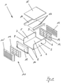
- FIG. 1 shows a housing 1 according to the invention in a schematic exploded view. When used as intended, this serves to accommodate two accumulator modules, with 8 lithium-ion accumulator cells electrically connected to one another being provided for each accumulator module. For the sake of a better overview, neither the accumulator modules nor the lithium-ion accumulator cells are shown individually in the figures.
- the housing according to the invention has a base body 2 which is U-shaped and has a base 3 and two side walls 4 and 5 arranged thereon.
- the base body 2 is preferably formed from a sheet metal which is folded to create the U-shaped configuration.
- the housing 1 also has front covers, namely a first front cover 10 and a second front cover 11.
- Front covers 10 and a second front cover 11 Two rear covers are provided opposite the front covers 10 and 11, namely a first rear cover 12 and a second rear cover 13.
- the first front cover 10 and the first rear cover 12 are screwed to the base body 2 .
- the base body 2 has attachment tabs 8 and attachment tabs 9 , the attachment tabs 8 being assigned to the first front cover 10 and the attachment tabs 9 to the first rear cover 12 .
- the housing 1 also has a first cover part 14 and a second cover part 15.
- the two cover parts 14 and 15 are in the final assembled state arranged at a distance from one another, so that a gap space 16 is formed between the first cover part 14 and the second cover part 15, as is shown in particular in accordance with the illustration figure 6 reveals.
- a fire protection material is arranged between the first front cover 10 and the second front cover 11 on the one hand and the first rear cover 12 and the second rear cover 13 on the other hand, which is not shown in detail in the figures.
- This fire protection material is preferably a mat woven, knitted or otherwise manufactured from a fire and heat resistant fibre.
- a covering made of a fire protection material which in the final assembled state rests against the second cover part 15, against the two side walls 4 and 5 and against the base 3.
- the casing formed from a fire protection material therefore surrounds the housing on the circumference, with inserts made of a fire protection material being provided on the front and rear of the housing, which are arranged between the first front cover 10 and the second front cover 11 and between the first rear cover 12 and the second rear cover 13 .
- the result is a full encapsulation of the lithium-ion accumulator cells accommodated by the housing in the intended case.
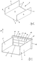
- Figures 2 to 12 show the individual housing components in different assembly steps in a second embodiment of the housing 1 according to the invention.
- FIG 2 shows the base body 2 of the housing 1 according to the invention.
- the bottom 3 and the side walls 4 and 5 are each equipped with fastening lugs 6, 7, 8 and 9 at the edges.
- These fastening lugs have unidentified threaded holes into which screws for arranging the front covers 10 and/or 11, the rear covers 12 and/or 13 and/or the cover parts 14 and/or 15 engage in the final assembled state.
- the fastening tabs 6 and 7 are on the second cover part 15, the fastening tabs 9 on the first rear cover 12 and the fastening tabs 8 on the first Front cover 10 assigned.
- rivets can also be provided, which is also preferred in terms of simplified pre-assembly by the manufacturer.
- FIG 3 shows the base body 2 with the rear cover 12 mounted.
- This is designed as a frame element and provides a passage opening 19 .
- This passage opening 19 is subdivided into individual openings 21 by means of webs 20 running transversely to one another.
- the fire protection mat arranged between the two rear covers 12 and 13 is supported on these webs 20 .
- the first rear cover 12 also has a terminating edge 33, with slits 25 being formed in the transition area to the terminating edge 33, which serve as receptacles for connecting means.
- figure 4 shows the base body 2 with the rear cover 12 mounted and the front cover 10 mounted.
- the front cover 10 is designed as a frame element and has a loading opening 18 through which lithium-ion accumulator cells or accumulator modules can be introduced into the volume space provided by the housing 1 on the user side.
- the first front cover 10 also provides bolts 22 on the upper side in the height direction 27, which serve as connecting means.
- figure 5 allows in addition figure 4 recognize the second rear cover 13 arranged on the first rear cover 12 in the final assembled state. This is preferably screwed to the first rear cover 12 .
- the second rear cover 13 is designed as a perforated plate. When the two rear covers 12 and 13 are screwed together, the fire protection material arranged between them is securely clamped between the two covers 12 and 13 . This prevents the fire protection material from slipping unintentionally.
- FIG 6 reveals a mounted first cover part 14 in a further supplement.
- This gap space 16 is fluidically connected via recesses 17 formed in the cover part 14 to the accommodation space provided by the housing 1 for accommodating the lithium-ion battery cells. In the event of a fire, smoke produced can thus reach the gap space 16 via the recesses 17, where intermediate storage takes place.
- the gap space 16 serves to supply cooling air, the gap space 16 being fluidically connected to the outside atmosphere surrounding the housing 1 via the individual openings 21 and the holes provided by the second rear cover 13 .
- the fire protection mat arranged between the rear covers 12 and 13 ensures that, in the event of a fire, no smoke can penetrate to the outside via the openings 21 and the holes formed in the second cover 13 .
- figure 7 allows in addition figure 6 recognize the fully assembled second cover part 15 .
- the housings 1 described above can be arranged stacked one on top of the other in the vertical direction 27 to form a housing arrangement 28 .
- the housing 1, which is arranged at the top in such a stacked case, is equipped with an end plate 26, as shown in figure 8 can be seen.
- the end plate 26 has connecting means receptacles 24 in the form of bores, into which the bolts 22 of the housing 1 underneath engage. In the final assembled state, therefore, the bolts serving as connecting means 22 engage in the correspondingly designed bores 24.
- This form-fitting Interlocking provides a positionally secure fixation of the end plate 26 in the horizontal direction.
- the closing plate 26 engages in the slots 25 provided by the closing edge 33 with the tabs 23 assigned to the closing edge 33 .
- the tabs 23 serve as connecting means and the slots 25 as connecting means receptacles designed to correspond thereto.
- This form-fitting arrangement enables the position of the end plate 26 to be fixed in the horizontal direction, at least in relation to the end edge 33, and otherwise in the vertical direction. Since the end plate 26 rests against the end edge 33, in combination with the bolt arrangements on the front, there is an additional positional fixation in the horizontal direction.
- FIG 9 shows a housing arrangement 28 according to the invention, the simplest conceivable case being shown here. Accordingly, the housing arrangement 28 has only one housing 1, which carries the closing plate 26 on the upper side and which is supported by a frame element 29 on the lower side.
- a terminal bridge 30, also known as a connector is provided for each housing 1, as is shown in figure 10 is shown.
- the second front cover 11 already described above is provided for each housing 1, such as this figure 11 reveals.
- the second front cover 11 provides corresponding slits for the passage of the terminal bridge 30, as can also be seen from an illustration figure 11 results.
- the design according to Figures 2 to 12 shows an embodiment according to which the second front cover 11 is formed in two parts and has a first part 11 and a second part 11'. while doing so 11 recognize the first part of the front cover 11.
- the first part 11 of the second front cover covers the loading opening 18 provided by the first front cover 10, as can be seen 11 results.
- a second part 11' of the second front cover covers the first part 11 of the second front cover.
- the second part 11' is the second front cover designed in the manner of a perforated plate and has circular recesses.
- the fire protection material provided on the front is arranged between the two parts 11 and 11' of the second front cover.
- the first part 11 of the second front cover also has webs which, in the final assembled state, support the fire protection material arranged between the two second front covers at the rear, so that the fire protection material is prevented from inadvertently penetrating into the volume space provided by the housing.
- FIG 13 shows a schematic perspective view of the frame element 29 already described above in a detailed illustration.
- the frame element 29 provides a frame 31 and a floor 32 arranged thereon.
- Two connecting means 22 in the form of bolts and two connecting means receptacles 25 in the form of slots are provided on the frame 31 .
- the housing 1 provided above the frame element 29 in the height direction 27 engages with its associated connecting means 23 or its connecting means receptacles 24 in the bolts 22 or the slots 25 of the frame element 29 .
- the Figures 14 to 16 show a housing arrangement 28 according to the invention in different perspective views, the housing arrangement 28 having a plurality of housings 1 of the type described above arranged one above the other in the height direction 27 .
- the upper closing plate 26 and the lower frame element 29 are not shown.
Landscapes
- Chemical & Material Sciences (AREA)
- Chemical Kinetics & Catalysis (AREA)
- Electrochemistry (AREA)
- General Chemical & Material Sciences (AREA)
- Inorganic Chemistry (AREA)
- Battery Mounting, Suspending (AREA)
Description
- Die Erfindung betrifft ein Gehäuse zur Aufnahme einer Lithium-Ionen-Akkumulatorzelle. Desweiteren betrifft die Erfindung eine Gehäuseanordnung, die über eine Mehrzahl von Gehäusen zur jeweiligen Aufnahme einer Lithium-Ionen-Akkumulatorzelle aufweist.
- Es sind aus dem Stand der Technik stationäre Energiespeicher zur Zwischenspeicherung von Strom bekannt. Derartige Energiespeicher können beispielsweise Stromnetzbetreibern und/oder stromerzeugenden Unternehmen dazu dienen, außerhalb von Stromspitzenzeiten anfallenden, überschüssigen Strom zwischen zu speichern, der dann zu Stromspitzenzeiten ins Netz eingespeist werden kann. Unerwünschte Stromschwankungen im Netz können damit vermieden werden.
- Stationäre Energiespeicher der eingangs genannten Art können durch sogenannte Großakkumulatoren gebildet sein, die jeweils über eine Mehrzahl von elektrisch miteinander verschalteten Akkumulatormodulen verfügen, wobei jedes Akkumulatormodul eine Mehrzahl von elektrisch miteinander verschalteten Akkumulatorzellen aufweist. Gemäß einer typischen Bauform kommen als Akkumulatorzellen Bleiakkumulatorenzellen zum Einsatz. Von Nachteil derartiger Bleiakkumulatorenzellen ist allerdings, dass sie zur Aufnahme oder Abgabe hoher Ströme innerhalb eines vergleichsweise kurzen Zeitraums weniger gut geeignet sind. Gerade aber die Eigenschaft, hohe Ströme innerhalb eines vergleichsweise kurzen Zeitraums aufnehmen oder abgeben zu können, ist eine bei stationären Energiespeichern der eingangs genannten Art erwünschte Eigenschaft.
- Um diese Eigenschaftsanforderung gerecht zu werden, sind aus dem Stand der Technik auch Großakkumulatoren bekannt geworden, die nicht auf Basis von Bleiakkumulatorzellen, sondern auf Basis von Lithium-Ionen-Akkumulatorzellen aufgebaut sind. Denn der Vorteil solcher Lithium-Ionen-Akkumulatorzellen besteht darin, dass sie hohe Ströme in vergleichsweiser kurzer Zeit sowohl bereitstellen als auch aufnehmen können. Von Nachteil bei Lithium-Ionen-Akkumulatorzellen ist jedoch, dass eine Tiefenentladung vermieden werden muss, genauso wie eine Überladung. Insbesondere ein Überladen von Lithium-Ionen-Akkumulatorzellen ist insoweit gefährlich, als dass es zu einer Brandauslösung oder gar Explosion kommen kann. Derartige Brände lassen sich dem Grunde nach nicht löschen, weil beim Brand einer Lithium-Ionen-Akkumulatorzelle Sauerstoff entsteht, so dass es mit herkömmlichen Löschmitteln, die die Sauerstoffzufuhr unterbinden, nicht möglich ist, Lithium-Ionen-Akkumulatorzellen zu löschen.
- Kommt es zu einem Brand einer Lithium-Ionen-Akkumulatorzelle besteht insbesondere bei einem Großakkumulator die Gefahr, dass der Brand auf benachbarte Lithium-Ionen-Akkumulatorzellen übergreift, so dass infolge der Überladung nur einer Lithium-Ionen-Akkumulatorzelle die Gefahr droht, dass der gesamte Großakkumulator abbrennt. Neben der Gefahr eines Brandübertrags auf dem Großakkumulator nebengeordneter Objekte und/oder Gebäudeteile ist der betriebswirtschaftliche Schaden zum Teil erheblich, denn Lithium-Ionen-Akkumulatoren sind in der Anschaffung sehr teuer.
- Um den vorgenannten Nachteilen zu begegnen, ist es aus dem Stand der Technik bekannt, Lithium-Ionen-Akkumulatorzellen zu kapseln, das heißt in einem Gehäuse unterzubringen, das dafür Sorge tragen soll, dass im Brandfall benachbarte Lithium-Ionen-Akkumulatorzellen nicht in Mitleidenschaft gezogen werden. Die insoweit vorbekannten Gehäusekonstruktionen sind in ihrem Aufbau sehr kompliziert, was eine Montage beziehungsweise Demontage erschwert und zeitlich aufwendig macht. Darüber hinaus haben sich vorbekannte Gehäuse insofern als untauglich herausgestellt, als dass sie nicht miteinander zur Ausbildung beispielsweise eines Großakkumulators sinnvoll kombiniert werden können. Es kommen deshalb bei Großakkumulatoren Regalsysteme zur Aufnahme von mehreren zueinander benachbarten Lithium-Ionen-Akkumulatorzellen zum Einsatz, welchen Regalsystemen wiederum der Nachteil anhaftet, dass es im Brandfall zu einer Ansteckung benachbarter Zellen kommen kann.
- Zur Behebung dieser widerstreitenden Eigenschaften ist es die Aufgabe der Erfindung, ein Gehäuse zur Aufnahme einer Lithium-Ionen-Akkumulatorzelle konstruktiv derart weiterzubilden, dass bei gleichzeitig effektivem Brandschutz für benachbarte Lithium-Ionen-Akkumulatorzellen ein einfacher Aufbau gegeben ist, der die Möglichkeit einer vereinfachten Montage beziehungsweise Demontage erbringt.
- Zur Lösung dieser Aufgabe wird mit der Erfindung vorgeschlagen ein Gehäuse zur Aufnahme einer Lithium-Ionen-Akkumulatorzelle, mit einem einen Boden und zwei Seitenwände aufweisenden, U-förmig ausgebildeten Grundkörper, mit einer ersten und einer zweiten Frontabdeckung und einer ersten und einer zweiten rückwärtigen Abdeckung, wobei zwischen erster und zweiter Frontabdeckung und zwischen erster und zweiter rückwärtiger Abdeckung jeweils ein Feuerschutzmaterial angeordnet ist, und mit einem ersten und einem zweiten Deckelteil, die unter Ausbildung eines Spaltraums beabstandet zueinander angeordnet sind, und mit einer an dem zweiten Deckelteil, an dem Boden und an den Seitenwänden anliegenden Umhüllung aus einem Feuerschutzmaterial, sowie mit in Gehäusehöhenrichtung gehäuseunterseitig und/oder gehäuseoberseitig vorgesehenen Verbindungsmitteln und gehäuseunterseitig und/oder gehäuseoberseitig vorgesehenen Verbindungsmittelaufnahmen, wobei die Verbindungsmittel und die Verbindungsmittelaufnahmen korrespondierend zueinander angeordnet sind.
- Das erfindungsgemäße Gehäuse verfügt als erste Baukomponente über einen Grundkörper. Dieser Grundkörper weist einen Boden und zwei Seitenwände auf. Dabei sind die Seitenwände einander gegenüberliegend am Boden angeordnet, so dass sich insgesamt eine U-förmige Ausgestaltung des Grundkörpers ergibt.
- Der Grundkörper ist bevorzugterweise einstückig ausgebildet und besteht aus einem abgekanteten Blechteil. Alternativ hierzu können der Boden und die Seitenwände auch separat voneinander ausgebildet und miteinander beispielsweise durch Schweißen verbunden sein.
- Der U-förmig ausgebildete Grundkörper ist frontseitig sowie rückseitig offen ausgebildet.
- Zum Verschluss dieser offenen Seiten sind Frontabdeckungen einerseits sowie rückwärtige Abdeckungen andererseits vorgesehen, die im endmontierten Zustand des Gehäuses am Grundkörper angeordnet sind. Bevorzugterweise sind die Frontabdeckungen und die rückwärtigen Abdeckungen mit dem Grundkörper verschraubt.
- Das Gehäuse verfügt über zwei Frontabdeckungen, nämlich eine erste Frontabdeckung und eine zweite Frontabdeckung. Im endmontierten Zustand ist zwischen der ersten Frontabdeckung einerseits und der zweiten Frontabdeckung andererseits ein Feuerschutzmaterial angeordnet. Bei diesem Feuerschutzmaterial handelt es sich um eine Matte aus einem feuerbeständigen Fasermaterial, welches erfindungsgemäß feuerdurchschlagsfest ist. Im endmontierten Zustand des Gehäuses ist dieses Feuerschutzmaterial zwischen erster und zweiter Frontabdeckung lagefixiert, womit eine feuerschutzgesicherte Gehäusefrontseite gegeben ist. Das Feuerschutzmaterial ist bevorzugterweise luftdurchlässig, nicht aber rauchdurchlässig ausgebildet. Die Luftdurchlässigkeit des Feuerschutzmaterials ist deshalb von Vorteil, als dass so die Möglichkeit gegeben ist, im bestimmungsgemäßen Betriebsfall Kühlluft in das Gehäuse einbringen zu können, wie dies im Weiteren noch näher erläutert werden wird.
- Das Gehäuse verfügt desweiteren über zwei rückwärtige Abdeckungen, und zwar eine erste rückwärtige Abdeckung und eine zweite rückwärtige Abdeckung. Im endmontierten Zustand ist zwischen diesen beiden rückwärtigen Abdeckungen ein Feuerschutzmaterial angeordnet, bei dem es sich bevorzugterweise um dasselbe Feuerschutzmaterial handelt, wie es zwischen erster Frontabdeckung und zweiter Frontabdeckung angeordnet ist. Im endmontierten Zustand ist das Feuerschutzmaterial zwischen den beiden rückseitigen Abdeckungen lagesicher fixiert, so dass eine rückwärtige Feuerschutzsicherung des Gehäuses gegeben ist.
- Das Gehäuse verfügt als weitere Baukomponente über ein erstes und ein zweites Deckelteil. Diese beiden Deckelteile sind im endmontierten Zustand unter Ausbildung eines Spaltraums beabstandet voneinander angeordnet. Dieser Spaltraum ist im endmontierten Zustand des Gehäuses luftgefüllt. Insoweit stellt der Spaltraum zwischen erstem Deckelteil und zweitem Deckelteil einen Luftraum bereit. Dieser Luftraum dient dazu, bei einem bestimmungsgemäßen Betrieb der vom Gehäuse aufgenommenen Lithium-Ionen-Akkumulatorzelle Kühlluft in das Gehäuse einbringen zu können. Diese Kühlluft dient einer Kühlung der Lithium-lonen-Akkumulatorzelle, was die Betriebssicherheit erhöht und insbesondere dafür Sorge trägt, dass ein unerwünscht weites Aufheizen der Lithium-Ionen-Akkumulatorzelle unterbleibt. Das Einbringen von als Kühlluft dienenden Luft in den Spaltraum zwischen erstem Deckelteil und zweitem Deckelteil erfolgt bevorzugterweise mittels einer dafür vorgesehenen Ventilatoreinheit, die beispielsweise rückseitig des Gehäuses aus der das Gehäuse umgebenden Atmosphäre Luft ansaugt und diese in den Spaltraum zwischen erstem Deckelteil und zweitem Deckelteil einbring. Auch eine frontseitige Zuführung von Kühlluft ist natürlich denkbar.
- Im Brandfall erfüllt der zwischen den beiden Deckenteilen ausgebildete Spaltraum zwei Funktionen. Zum einen wird ein Luftpolster geschaffen, das thermisch isolierend wirkt. Im Brandfall entstehende Hitze wirkt mithin nicht direkt auf das zweite, äußere Deckelteil ein, sondern vielmehr nur indirekt unter Zwischenschaltung des ersten Deckelteils und des zwischen erstem Deckelteil und zweitem Deckelteil ausgebildeten Spaltraums. Damit ergibt sich im Brandfall ein deutlich reduzierter Hitzeintrag in das außen liegende, zweite Deckelteil.
- Im Brandfall dient der Spaltraum desweiteren dazu, entstehenden Rauch aufnehmen zu können. Denn das im Gehäuse insgesamt verbaute Feuerschutzmaterial hält im Brandfall entstehenden Rauch zurück und sorgt in vorteilhafter Weise dafür, dass kein Rauch nach außen in die Atmosphäre austreten kann. Insofern dient der zwischen erstem Deckelteil und zweitem Deckelteil ausgebildete Spaltraum als Rauchausweichraum, in den der im Brandfall entstehende Rauch einströmen kann.
- Als weitere Baukomponente verfügt das Gehäuse über eine Umhüllung aus einem Feuerschutzmaterial. Diese Umhüllung aus einem Feuerschutzmaterial liegt im endmontierten Zustand des Gehäuses am zweiten Deckelteil, an dem dem zweiten Deckelteil gegenüberliegenden Boden des Grundkörpers sowie an den Seitenwänden des Grundkörpers an. Bei dem Feuerschutzmaterial für die Umhüllung kann es sich im Vergleich zum Feuerschutzmaterial zwischen den Frontabdeckungen bzw. den rückwärtigen Abdeckungen um ein anderes Feuerschutzmaterial handeln. Denn das die Umhüllung bildende Feuerschutzmaterial ist im bestimmungsgemäßen Betriebsfall nicht von Kühlluft durchströmt und braucht deshalb auch nicht luftdurchlässig ausgebildet sein. Insoweit ist auch ein keramikgleiches Feuerschutzmaterial bevorzugt, welches das Gehäuse auch im Falle einer großen Hitzeentwicklung im Brandfall derart sicher umgibt, dass ein Feuer- und/oder Hitzedurchschlag auf benachbarte Gehäuse sicher vermieden ist.
- Im Ergebnis dieser Ausgestaltung ist eine Vollkapselung mit Feuerschutzmaterial gegeben, wobei die Umhüllung das Gehäuse über den Boden, die beiden Seitenwände und das zweite Deckelteil umlaufend umgibt, und wobei ein frontseitiger Schutz beziehungsweise ein rückwärtiger Schutz durch das Feuerschutzmaterial gegeben ist, das zwischen den beiden Frontabdeckungen beziehungsweise zwischen den beiden rückwärtigen Abdeckungen angeordnet ist. Die Vollkapselung sorgt dafür, dass im Brandfall sichergestellt ist, dass es zu keinem Rauchaustritt kommen kann und dass kein Feuer auf benachbarte Lithium-Ionen-Akkumulatorzellen übergreifen kann, womit eine kaskadierende Ansteckung benachbarter Lithium-Ionen-Akkumulatorzellen sicher unterbunden ist.
- Das Gehäuse verfügt desweiteren über Verbindungsmittel einerseits sowie über Verbindungsmittelaufnahmen andererseits. Dabei sind die Verbindungsmittel beziehungsweise die Verbindungsmittelaufnahmen in Gehäusehöhenrichtung gehäuseunterseitig und/oder gehäuseoberseitig ausgebildet. Demnach können entweder gehäuseoberseitig Verbindungsmittel und gehäuseunterseitig Verbindungsmittelaufnahmen vorgesehen sein. Eine umgekehrte Anordnung ist ebenfalls denkbar. Auch eine Mischausgestaltung, wonach gehäuseunterseitig und gehäuseoberseitig sowohl Verbindungsmittel als auch Verbindungsmittelaufnahmen vorgesehen sind, ist möglich und gemäß einer Ausführungsform der Erfindung auch bevorzugt.
- Die Verbindungsmittel beziehungsweise die Verbindungsmittelaufnahmen dienen dazu, mehrere Gehäuse der vorbeschriebenen Art zu einem Gehäusestapel übereinander anzuordnen, und zwar lagesicher. Dabei greifen die Verbindungsmittel beziehungsweise Verbindungsmittelaufnahmen benachbarter Gehäuse bevorzugterweise derart ineinander, dass eine Lagefixierung der Gehäuse relativ zueinander sowohl in Höhenrichtung als auch quer hierzu gegeben ist.
- Um die Kompatibilität der Verbindungsmittel zu den Verbindungsmittelaufnahmen zu gewährleisten, sind die Verbindungsmittel und die Verbindungsmittelaufnahmen korrespondierend zueinander ausgebildet, erlauben also im endmontierten Zustand mehrerer zu einem Gehäusestapel miteinander kombinierter Gehäuse ein bestimmungsgemäßes Eingreifen ineinander, so dass bevorzugterweise sowohl in vertikaler Richtung als auch in horizontaler Richtung ein lagesicheres Übereinanderstapeln einzelner Gehäuse ermöglicht ist.
- Im Ergebnis der erfindungsgemäßen Konstruktion steht, dass das Gehäuse aus einzelnen Baukomponenten gebildet ist, die in denkbar einfacher Weise miteinander kombiniert und montiert werden können. Die Verbindung der einzelnen Gehäusekomponenten erfolgt beispielsweise durch Verschrauben. Dies erlaubt im Reparaturfall eine einfache Demontage. Es können aber auch andere Verbindungstechniken gewählt werden, beispielsweise wieder lösbare Rastverbindungen.
- Zudem erlauben es die gehäuseseitig vorgesehenen Verbindungsmittel und Verbindungsmittelaufnahmen, dass mehrere Gehäuse miteinander zu einem Gehäusestapel kombiniert werden können, und dies bevorzugterweise werkzeugfrei. Dabei greifen die Verbindungsmittel und die Verbindungsmittelaufnahmen benachbarter Gehäuse formschlüssig derart ineinander, dass bevorzugterweise sowohl in horizontaler Richtung als auch in vertikaler Richtung eine Lagefixierung gegeben ist, womit es ergänzender Gehäusestapelsicherungen nicht bedarf.
- Die im endmontierten Zustand vom Gehäuse aufgenommene Lithium-Ionen-Akkumulatorzelle ist erfindungsgemäße vollständig innerhalb eines Feuerschutzmaterials gekapselt angeordnet. Damit ist wirkungsvoll sichergestellt, dass es im Brandfall nicht zu einem Feuerübertrag auf benachbarte Gehäuse kommen kann.
- Die erfindungsgemäße Gehäusekonstruktion erbringt aufgrund des zwischen dem ersten Deckelteil und dem zweiten Deckelteil ausgebildeten Spaltraums zudem den Vorteil, dass ein Hitzeeintrag im Brandfall in das zweite, äußere Deckelteil deutlich reduziert ist. Dieser Vorteil kommt insbesondere bei einer Übereinanderordnung mehrerer Gehäuse zum Tragen, weil sich dann mit Ausnahme für die im Gehäusestapel zu oberst und zu unterst angeordneten Lithium-Ionen-Akkumulatorzellen je Lithium-Ionen-Akkumulatorzelle zwei thermisch isolierend wirkende Luftpolster ergeben, die je Lithium-Ionen-Akkumulatorzelle in Höhenrichtung jeweils oberseitig und unterseitig der Lithium-Ionen-Akkumulatorzelle ausgebildet sind.
- Die vorbeschriebenen Merkmale des erfindungsgemäßen Gehäuses wirken synergetisch zusammen und erbringen in ihrer Kombination die schon vorstehend erläuterten Vorteile. Damit eignet sich das erfindungsgemäße Gehäuse insbesondere dazu, Lithium-Ionen-Akkumulatorzellen zu einem Großakkumulator zur Ausbildung eines stationären Energiespeichers miteinander zu kombinieren.
- Zur Ausbildung eines Großakkumulators ist es bevorzugt, eine Mehrzahl von Lithium-lonen-Akkumulatorzellen zu einem Akkumulatormodul miteinander zu kombinieren. So können beispielsweise 8 Lithium-Ionen-Akkumulatorzellen mit je 248,2 W/h miteinander zu einem Akkumulatormodul kombiniert sein, welches Modul dann ca. 1,98 kW/h bereitstellt.
- Ein erfindungsgemäßes Gehäuse kann in seinen Größenabmessungen bevorzugterweise derart ausgebildet sein, dass es zwei solcher Akkmulatormodule aufnimmt, mithin insgesamt 16 Lithium-Ionen-Akkumulatorzellen.
- Gemäß dieser vorgeschlagenen Ausführungsform ist im Brandfall der Schaden auf zwei Akkumulatormodule, mithin auf 16 Lithium-Ionen-Akkumulatorzellen beschränkt.
- Die beiden von einem erfindungsgemäßen Gehäuse aufgenommenen Akkumulatormodule bilden zusammen eine Moduleinheit. Zur Ausbildung eines Großakkumulators können beispielsweise 16 solcher Moduleinheiten miteinander kombiniert werden, womit in Summe 256 Lithium-Ionen-Akkumulatorzellen vorliegen. Diese 16 Moduleinheiten bilden ein sogenanntes Powerrack. 10 solcher Powerracks können in einem herkömmlichen Transportcontainer (Überseecontainer) untergebracht sein, womit ein so ausgebildeter Großakkumulator im Bedarfsfall in einfacher Weise betrieben und auch transportiert werden kann.
- Zur Ausbildung eines Powerracks können zwei Stapel von Moduleinheiten ausgebildet werden, wobei je Moduleinheitenstapel 8 Moduleinheiten vorgesehen sind. Dabei beherbergt jede Moduleinheit zwei in einem erfindungsgemäßen Gehäuse angeordnete Module, wobei die Moduleinheitenstapel in einfacher Weise dadurch ausgebildet werden, dass die erfindungsgemäßen Gehäuse in schon vorbeschriebener Weise übereinander angeordnet werden, wobei dann im Nachgang einer solchen Übereinanderstapelung je Gehäuse eine Bestückung mit zwei Modulen stattfinden kann. Die gehäuseseits jeweils vorgesehenen Verbindungsmittel beziehungsweise Verbindungsmittelaufnahmen sorgen für einen sicheren Halt der übereinander angeordneten Gehäuse, womit im endmontierten Zustand der Moduleinheitenstapel eine lagesichere und -fixierte Stapelanordnung gegeben ist.
- Die einzelnen Gehäusekomponenten bestehen bevorzugterweise aus einem korrosionsfesten Metall, vorzugsweise in einer vergleichsweise dicken Blechstärke. Dies deshalb, damit im Brandfall ein nicht unerheblicher Teil der frei werdenden Hitze vom Gehäuse selbst aufgenommen und damit von benachbarten Gehäusen abgehalten werden kann. Die Wärmeschutzummantelung des Gehäuses durch das Feuerschutzmaterial sorgt indes dafür, dass ein Wärmeübertrag auf benachbarte Gehäuse sicher unterbunden ist.
- Es ist gemäß einem weiteren Merkmal der Erfindung vorgesehen, dass das erste Deckenteil Ausnehmungen aufweist. Das erste Deckelteil ist in Höhenrichtung unterhalb des zweiten Deckelteils angeordnet, wobei zwischen erstem Deckelteil und zweitem Deckelteil ein luftgefüllter Spaltraum ausgebildet ist. Dieser Spaltraum dient im Brandfall der Aufnahme von Rauch, wobei zwecks Einleitung von Rausch in den zwischen erstem Deckelteil und zweitem Deckelteil vorgesehenen Spaltraum Ausnehmungen im ersten Deckelteil ausgebildet sind. Die im ersten Deckelteil erfindungsgemäß vorgesehenen Ausnehmungen ermöglichen mithin einen Rauchübertritt, aus dem vom Gehäuse bereitgestellten Volumenraum zur Aufnahme der Lithium-Ionen-Akkumulatorzellen in den zwischen den beiden Deckelteilen ausgebildeten Spaltraum.
- Gemäß einem weiteren Merkmal der Erfindung ist vorgesehen, dass die erste Frontabdeckung eine Beschickungsöffnung bereitstellt. Diese Beschickungsöffnung dient im endmontierten Zustand des Gehäuses dazu, Lithium-Ionen-Akkumulatorzellen beziehungsweise aus Lithium-Ionen-Akkmulatorzellen gebildete Akkumulatormodule in das Gehäuse einbringen zu können. Die frontseitige Ausgestaltung einer Beschickungsöffnung gestattet es mithin, die diesbezügliche Frontabdeckung endfertig am Grundkörper des Gehäuses anzuordnen, bevor eine Beschickung des Gehäuses mit Lithium-Ionen-Akkumulatorzellen beziehungsweise Akkumulatormodulen erfolgt. Diese konstruktive Ausgestaltung ermöglicht mithin eine herstellerseitige Vormontage des Gehäuses, womit am Aufstellungsort nur noch eine Bestückung des Gehäuses mit anschließender Montage nur noch der zweiten Frontabdeckung erfolgen kann.
- Gemäß einem weiteren Merkmal der Erfindung ist vorgesehen, dass die rückwärtige Abdeckung eine Durchlassöffnung bereitstellt. Diese Durchlassöffnung dient insbesondere im bestimmungsgemäßen Betriebsfall dazu, Kühlluft von außen in den Spaltraum zwischen erstem und zweitem Deckelteil einbringen zu können. Dabei ist die Durchlassöffnung bevorzugterweise mittels quer zueinander verlaufender Stege in Einzelöffnungen unterteilt. Diese quer zueinander verlaufenden Stege dienen insbesondere einer Abstützung des zwischen der ersten rückwärtigen Abdeckung und der zweiten rückwärtigen Abdeckung angeordneten Feuerschutzmaterials. Einerseits wird so die lagesichere Fixierung des Feuerschutzmaterials zwischen den beiden rückwärtigen Abdeckungen sichergestellt, sowie andererseits ein Einwandern des Feuerschutzmaterials in den vom Gehäuse bereitgestellten Volumenraum verhindert. Insgesamt ist so eine vollflächige Abdeckung der rückwärtigen Gehäuseseite durch das zwischen den rückwärtigen Abdeckungen angeordnete Feuerschutzmaterial sichergestellt.
- Gemäß einem weiteren Merkmal der Erfindung ist die zweite rückwärtige Abdeckung ein Lochblech. Die zweite rückwärtige Abdeckung stellt mithin eine Vielzahl von Durchtrittsöffnungen zur Verfügung, durch die hindurch im bestimmungsgemäßen Betriebsfall von außen Kühlluft in das Gehäuseinnere strömen kann.
- Gemäß einem weiteren Merkmal der Erfindung ist vorgesehen, dass die erste Frontabdeckung und die erste rückwärtige Abdeckung jeweils als Rahmenelement ausgebildet sind. Dies erbringt im endmontierten Zustand des Gehäuses eine Versteifung, so dass konstruktiv die für einen sicheren Betrieb der vom Gehäuse aufgenommenen Lithium-Ionen-Akkumulatorzellen erforderliche Tragfähigkeit des Gehäuses gegeben ist. Bevorzugterweise sind die Frontabdeckung und die rückwärtige Abdeckung mit dem Grundkörper verschraubt, was einerseits eine einfache Montage gestattet, andererseits aber auch eine Demontage ermöglicht.
- Gemäß einem weiteren Merkmal der Erfindung ist vorgesehen, dass die erste Frontabdeckung und die erste rückwärtige Abdeckung den Grundkörper allseitig überragen. Sowohl die Frontabdeckung als auch die rückwärtige Abdeckung stehen mithin umfangsseitig über den Grundkörper hinaus vor. Es ist so eine Art Vorsprung zwischen Grundkörper und Frontabdeckung beziehungsweise rückwärtiger Abdeckung ausgebildet. Dieser Vorsprung dient der Aufnahme der am zweiten Deckelteil, den beiden Seitenwänden und dem Boden anliegenden Umhüllung aus einem Feuerschutzmaterial, so dass im endfertig montierten Zustand ein insgesamt bündiger Abschluss gegeben ist.
- Gemäß einem weiteren Merkmal der Erfindung ist vorgesehen, dass das erste Deckelteil in Gehäusehöhenrichtung unterhalb der oberen Abschlusskante von der ersten Frontabdeckung und von der ersten rückwärtigen Abdeckung angeordnet ist. Durch diese in Höhenrichtung nach unten versetzte Anordnung des ersten Deckelteils ergibt sich der im endmontierten Zustand zwischen erstem Deckelteil und zweitem Deckelteil ausgebildete Spaltraum. Dieser Spaltraum erbringt die schon vorstehend erläuterten Vorteile, und zwar sowohl während eines bestimmungsgemäßen Betriebs als auch im Brandfall.
- Gemäß einem weiteren Merkmal der Erfindung ist vorgesehen, dass die Verbindungsmittel Vorsprünge sind, beispielsweise Bolzen, Laschen, Absätze und/oder dergleichen. Diese lassen sich in einfacher Weise an einem der Gehäuseteile des Gehäuses anordnen beziehungsweise einstückig mit diesen ausbilden.
- Die Verbindungsmittelaufnahmen sind gemäß einem weiteren Merkmal der Erfindung Ausnehmungen zur formschlüssigen Aufnahme von Verbindungsmitteln, wie zum Beispiel Bohrungen, Nuten, Schlitze und/oder dergleichen. In derartige Ausnehmungen greifen im endmontierten Zustand die korrespondierend hierzu ausgebildeten Verbindungsmittel. Dabei ist es bevorzugt, zur Lagesicherung in horizontaler Richtung und/oder vertikaler Richtung Verbindungsmittel mit Hinterschnitt auszubilden, so dass eine hintergreifende Anordnung in den zugehörigen Verbindungsmittelaufnahmen entsteht.
- Gemäß einem weiteren Merkmal der Erfindung wird eine Gehäuseanordnung vorgeschlagen. Im einfachsten Ausführungsfall verfügt eine solche Gehäuseanordnung über ein Gehäuse der vorstehend beschriebenen Art, ein das Gehäuse aufnehmende Rahmenelement, wie dies im Weiteren noch erläutert werden wird, sowie eine gehäuseseitig ausgebildete Abschlussplatte. Bevorzugt ist indes aber eine Gehäuseanordnung mit einer Mehrzahl von in Höhenrichtung übereinander angeordneten Gehäusen gemäß der vorbeschriebenen Art, wobei die Verbindungsmittel eines Gehäuses in die Verbindungsmittelaufnahmen des in Höhenrichtung darüber und/oder darunter angeordneten Gehäuses eingreifen. Im übereinander geordneten Zustand der Gehäuse ergibt sich eine Art Regalausgestaltung. Dabei können je Gehäuse eine Mehrzahl von Lithium-Ionen-Akkumulatorzellen beziehungsweise eine Vielzahl von aus Lithium-Ionen-Akkumulatorzellen aufgebauten Akkumulatormodule aufgenommen werden. Je nach Anzahl der übereinander gestapelten Gehäuse kann eine entsprechende Anzahl von Lithium-Ionen-Akkumulatorzellen beziehungsweise Akkumulatormodule je Gehäusestapel aufgenommen werden. Dabei sorgen die gehäuseseits vorgesehenen Verbindungsmittel beziehungsweise Verbindungsmittelaufnahmen dafür, dass übereinander angeordnete Gehäuse lagesicher in ihrer relativen Ausrichtung zueinander positioniert sind. Die formschlüssig ineinandergreifenden Verbindungsmittel beziehungsweise Verbindungsmittelaufnahmen ermöglichen es, dass eine Gehäuseübereinanderstapelung werkzeugfrei erfolgen kann, was eine besonders einfache Montage beziehungsweise Demontage gestattet.
- Die Gehäuseanordnung verfügt gemäß einem weiteren Merkmal der Erfindung über ein Rahmenelement, das unterhalb des in Höhenrichtung zu unterst angeordneten Gehäuses angeordnet ist. Ein solches Rahmenelement dient als Basis für eine Gehäuseübereinanderstapelung. Zu diesem Zweck ist das Rahmenelement aufstellbodenseitig plan ausgebildet, so dass ein kippfreier Stapelstand möglich ist. Oberseitig verfügt das Rahmenelement über entsprechende Verbindungsmittel und/oder Verbindungsmittelaufnahmen, in die die korrespondierend hierzu ausgebildete Verbindungsmittel beziehungsweise Verbindungsmittelaufnahmen des im Gehäusestapel zu unterst angeordneten Gehäuses eingreifen können. Es wird so eine lagesichere Anordnung des im Gehäusestabel zu unterst angeordneten Gehäuses relativ zum darunterliegenden Rahmenelement erreicht.
- Gemäß einem weiteren Merkmal der Erfindung ist eine Gehäuseanordnung vorgesehen, die über eine Mehrzahl von nebeneinander angeordneten Gehäusestapeln verfügt, die jeweils eine Mehrzahl von in Höhenrichtung übereinander angeordneten Gehäuse der vorbeschriebenen Art aufweist. Dabei sind benachbarte Gehäusestapel miteinander verbunden, insbesondere miteinander verschraubt. Eine solche Verschraubung ist aufgrund der lagesicheren Anordnung der einzelnen Gehäuse dem Grunde nach nicht erforderlich, erhöht aber gleichwohl die Standsicherheit der einzelnen Gehäusestapel. Diese zusätzliche Standsicherheit ist insbesondere dann von Vorteil, wenn die zur Ausbildung eines Großakkumulators miteinander zu kombinierenden Gehäusestapel innerhalb eines Containers angeordnet sind, der im Bedarfsfall einen einfachen Transport ermöglicht.
- Weitere Merkmale und Vorteile der Erfindung ergeben sich aus der nachfolgenden Beschreibung anhand der Figuren. Dabei zeigen:
- Fig. 1
- in schematischer Explosionsdarstellung ein erfindungsgemäßes Gehäuse;
- Fig. 2 bis 12
- in jeweils schematisch perspektivischer Ansicht das Gehäuse nach der Erfindung in unterschiedlichen Montagezuständen;
- Fig. 13
- in schematisch perspektivischer Ansicht ein Rahmenelement einer erfindungsgemäßen Gehäuseanordnung;
- Fig. 14 bis 16
- in jeweils perspektivischer Ansicht eine erfindungsgemäße Gehäuseanordnung aus unterschiedlichen Blickrichtungen.
-
Figur 1 lässt in schematischer Explosionsdarstellung ein Gehäuse 1 nach der Erfindung erkennen. Dieses dient im bestimmungsgemäßen Verwendungsfall der Aufnahme von zwei Akkumulatormodulen, wobei je Akkumulatormodul 8 elektrisch miteinander verschaltete Lithium-Ionen-Akkumulatorzellen vorgesehen sind. Der besseren Übersicht wegen sind in den Figuren weder die Akkumulatormodule noch die Lithium-Ionen-Akkumulatorzellen im Einzelnen dargestellt. - Das erfindungsgemäße Gehäuse verfügt über einen Grundkörper 2, der U-förmig ausgebildet ist und einen Boden 3 sowie zwei daran angeordnete Seitenwände 4 und 5 aufweist. Der Grundkörper 2 ist bevorzugterweise aus einem Metallblech ausgebildet, das zur Schaffung der U-förmigen Ausgestaltung abgekantet ist.
- Das Gehäuse 1 verfügt desweiteren über Frontabdeckungen, nämlich eine erste Frontabdeckung 10 und eine zweite Frontabdeckung 11. Den Frontabdeckungen 10 und 11 gegenüberliegend sind zwei rückwärtige Abdeckungen vorgesehen, nämlich eine erste rückwärtige Abdeckung 12 sowie eine zweite rückwärtige Abdeckung 13.
- Im endmontierten Zustand sind die erste Frontabdeckung 10 und die erste rückwärtige Abdeckung 12 mit dem Grundkörper 2 verschraubt. Zu diesem Zweck weist der Grundkörper 2 Befestigungslaschen 8 sowie Befestigungslaschen 9 auf, wobei die Befestigungslaschen 8 der ersten Frontabdeckung 10 und die Befestigungslaschen 9 der ersten rückwärtigen Abdeckung 12 zugeordnet sind.
- Das Gehäuse 1 verfügt desweiteren über ein erstes Deckelteil 14 und ein zweites Deckelteil 15. Im endmontierten Zustand sind die beiden Deckelteile 14 und 15 beabstandet zueinander angeordnet, so dass sich zwischen dem ersten Deckelteil 14 und dem zweiten Deckelteil 15 ein Spaltraum 16 ausbildet, wie dies insbesondere die Darstellung nach
Figur 6 erkennen lässt. - Im endmontierten Zustand ist zwischen der ersten Frontabdeckung 10 und der zweiten Frontabdeckung 11 einerseits und der ersten rückwärtigen Abdeckung 12 und der zweiten rückwärtigen Abdeckung 13 andererseits jeweils ein Feuerschutzmaterial angeordnet, welches in den Figuren nicht im Einzelnen dargestellt ist. Bei diesem Feuerschutzmaterial handelt es sich bevorzugterweise um eine Matte, die aus einer feuer- und hitzebeständigen Faser gewebt, gewirkt oder sonstwie hergestellt ist.
- In den Figuren nicht dargestellt ist desweiteren eine Umhüllung aus einem Feuerschutzmaterial vorgesehen, die im endmontierten Zustand am zweiten Deckelteil 15, an den beiden Seitenwänden 4 und 5 sowie an dem Boden 3 anliegt. Die aus einem Feuerschutzmaterial gebildete Umhüllung umgibt das Gehäuse mithin umfangsseitig, wobei gehäusefrontseitig und gehäuserückseitig jeweils Einlagen aus einem Feuerschutzmaterial vorgesehen sind, die zwischen der ersten Frontabdeckung 10 und der zweiten Frontabdeckung 11 beziehungsweise zwischen der ersten rückwärtigen Abdeckung 12 und der zweiten rückwärtigen Abdeckung 13 angeordnet sind. Im Ergebnis ergibt sich so eine Vollkapselung der vom Gehäuse im bestimmungsgemäßen Fall aufgenommenen Lithium-Ionen-Akkumulatorzellen.
- Die weiteren
Figuren 2 bis 12 lassen an einer zweiten Ausführungsform des erfindungsgemäßen Gehäuses 1 die einzelnen Gehäusekomponenten in unterschiedlichen Montageschritten erkennen. -
Figur 2 zeigt den Grundkörper 2 des erfindungsgemäßen Gehäuses 1. Wie sich aus dieser Darstellung ergibt, sind der Boden 3 und die Seitenwände 4 und 5 randseitig jeweils mit Befestigungslaschen 6, 7, 8 beziehungsweise 9 ausgerüstet. Diese Befestigungslaschen weisen nicht näher identifizierte Gewindebohrungen auf, in die im endmontierten Zustand Schrauben zur Anordnung der Frontabdeckungen 10 und/oder 11, der rückwärtigen Abdeckungen 12 und/oder 13 und/oder der Deckelteile 14 und/oder 15 eingreifen. Dabei sind die Befestigungslaschen 6 und 7 dem zweiten Deckelteil 15, die Befestigungslaschen 9 der ersten rückwärtigen Abdeckung 12 und die Befestigungslaschen 8 der ersten Frontabdeckung 10 zugeordnet. Anstelle von Verschraubungen zur Verbindung der einzelnen Baukomponenten können auch Nieten vorgesehen sein, was im Sinne einer vereinfachten herstellerseitigen Vormontage auch bevorzugt ist. -
Figur 3 lässt den Grundkörper 2 mit montierter rückwärtiger Abdeckung 12 erkennen. Diese ist als Rahmenelement ausgebildet und stellt eine Durchtrittsöffnung 19 bereit. Diese Durchtrittsöffnung 19 ist mittels quer zueinander verlaufender Stege 20 in Einzelöffnungen 21 unterteilt. An diesen Stegen 20 stützt sich im endmontierten Zustand die zwischen den beiden rückwärtigen Abdeckungen 12 und 13 angeordnete Feuerschutzmatte ab. - Die erste rückwärtige Abdeckung 12 verfügt desweiteren über eine Abschlusskante 33, wobei im Übergangsbereich zur Abschlusskante 33 Schlitze 25 ausgebildet sind, die als Verbindungsmittelaufnahmen dienen.
-
Figur 4 lässt den Grundkörper 2 mit montierter rückwärtiger Abdeckung 12 und montierter Frontabdeckung 10 erkennen. - Die Frontabdeckung 10 ist als Rahmenelemente ausgebildet und verfügt über eine Beschickungsöffnung 18, durch welche hindurch verwenderseitig Lithium-Ionen-Akkumulatorzellen beziehungsweise Akkumulatormodule in den vom Gehäuse 1 bereitgestellten Volumenraum eingebracht werden können. Die erste Frontabdeckung 10 stellt in Höhenrichtung 27 oberseitig zudem Bolzen 22 bereit, die als Verbindungsmittel dienen.
-
Figur 5 lässt in Ergänzung zuFigur 4 die im endmontierten Zustand an der ersten rückwärtigen Abdeckung 12 angeordnete zweite rückwärtige Abdeckung 13 erkennen. Diese ist bevorzugterweise mit der ersten rückwärtigen Abdeckung 12 verschraubt. Im gezeigten Ausführungsbeispiel ist die zweite rückwärtige Abdeckung 13 als Lochblech ausgebildet. Im verschraubten Zustand der beiden rückwärtigen Abdeckungen 12 und 13 ist das dazwischen angeordnete Feuerschutzmaterial zwischen den beiden Abdeckungen 12 und 13 lagesicher eingeklemmt. Ein ungewolltes Verrutschen des Feuerschutzmaterials ist so verhindert. -
Figur 6 lässt in einer weiteren Ergänzung ein montiertes erstes Deckelteil 14 erkennen. Im endmontierten Zustand bildet sich zwischen dem ersten Deckelteil 14 und dem inFigur 6 nicht dargestellten zweiten Deckelteil 15 ein Spaltraum 16 aus. Dieser Spaltraum 16 steht über im Deckelteil 14 ausgebildete Ausnehmungen 17 in strömungstechnischer Verbindung mit dem vom Gehäuse 1 bereitgestellten Aufnahmeraum zur Aufnahme der Lithium-Ionen-Akkumulatorzellen. Im Brandfall entstehender Rauch kann so über die Ausnehmungen 17 in den Spaltraum 16 gelangen, wo eine Zwischenspeicherung erfolgt. - Im bestimmungsgemäßen Betriebsfall dient der Spaltraum 16 der Zuführung von Kühlluft, wobei der Spaltraum 16 über die Einzelöffnungen 21 und die von der zweiten rückwärtigen Abdeckung 13 bereitgestellten Löcher in strömungstechnischer Verbindung mit der das Gehäuse 1 umgebenden Außenatmosphäre steht. Dabei sorgt die zwischen den rückwärtigen Abdeckungen 12 und 13 angeordnete Feuerschutzmatte dafür, dass im Brandfall kein Rauch über die Öffnungen 21 und die in der zweiten Abdeckung 13 ausgebildeten Löcher nach außen dringen kann.
-
Figur 7 lässt in Ergänzung zuFigur 6 das endfertig montierte zweite Deckelteil 15 erkennen. - Wie sich aus der Darstellung nach
Figur 7 ergibt, stehen die erste Frontabdeckung 10 sowie die erste rückwärtige Abdeckung 12 allumseitig über das zweite Deckelteil 15, die beiden Seitenwände 4 und 5 sowie den Boden 3 hinaus über. Es ist so ein Aufnahmeraum für die Umhüllung aus einem Feuerschutzmaterial geschaffen, die im endmontierten Zustand am zweiten Deckelteil 15, den beiden Seitenwänden 4 und 5 sowie dem Boden 3 anliegt. - Mehrere der nach den
Figuren 1 bis 7 vorbeschriebenen Gehäuse 1 können in Höhenrichtung 27 zu einer Gehäuseanordnung 28 übereinandergestapelt angeordnet werden. Das in einem solchen Stapelfall zu oberst angeordnete Gehäuse 1 ist mit einer Abschlussplatte 26 ausgerüstet, wie diese inFigur 8 zu erkennen ist. Wie sich aus dieser Darstellung ergibt, verfügt die Abschlussplatte 26 über Verbindungsmittelaufnahmen 24 in Form von Bohrungen, in die die Bolzen 22 des darunterliegenden Gehäuses 1 eingreifen. Im endmontierten Zustand greifen mithin die als Verbindungsmittel 22 dienenden Bolzen in die korrespondierend hierzu ausgebildeten Bohrungen 24. Dieses formschlüssige Ineinandergreifen erbringt eine lagesichere Fixierung der Abschlussplatte 26 in horizontaler Richtung. - Die Abschlussplatte 26 greift mit der Abschlusskante 33 zugeordneten Laschen 23 in die von der Abschlusskante 33 bereitgestellten Schlitze 25 ein. Dabei dienen die Laschen 23 als Verbindungsmittel und die Schlitze 25 als hierzu korrespondierend ausgebildete Verbindungsmittelaufnahmen. Diese formschlüssige Anordnung ermöglicht zumindest mit Bezug auf die Abschlusskante 33 eine Lagefixierung der Abschlussplatte 26 in horizontaler Richtung, im Übrigen in vertikaler Richtung. Da die Abschlussplatte 26 im Übrigen an der Abschlusskante 33 anliegt, ist in Kombination mit den frontseitigen Bolzen-Anordnungen eine zusätzliche Lagefixierung in horizontaler Richtung gegeben.
-
Figur 9 lässt eine erfindungsgemäße Gehäuseanordnung 28 erkennen, wobei hier der denkbar einfachste Fall dargestellt ist. Demgemäß verfügt die Gehäuseanordnung 28 nur über ein Gehäuse 1, das oberseitig die Abschlussplatte 26 trägt und welches unterseitig von einem Rahmenelement 29 abgestützt ist. - Zur elektrischen Verbindung der von mehreren Gehäusen 1 aufgenommenen Lithium-Ionen-Akkumulatorzellen ist je Gehäuse 1 eine Polbrücke 30, auch Verbinder genannt, vorgesehen, wie dies in
Figur 10 dargestellt ist. - Im endmontierten Zustand ist je Gehäuse 1 die schon vorstehend beschriebene zweite Frontabdeckung 11 vorgesehen, wie dies
Figur 11 erkennen lässt. Dabei stellt die zweite Frontabdeckung 11 entsprechende Schlitze zur Hindurchführung der Polbrücke 30 zur Verfügung, wie sich dies ebenfalls aus einer Anschau nachFigur 11 ergibt. - Die Ausgestaltung nach den
Figuren 2 bis 12 lässt eine Ausführungsform erkennen, dergemäß die zweite Frontabdeckung 11 zweiteilig ausgebildet ist und über einen ersten Teil 11 und einen zweiten Teil 11' verfügt. Dabei lässtFig. 11 den ersten Teil der Frontabdeckung 11 erkennen. Im endmontierten Zustand deckt der erste Teil 11 der zweiten Frontabdeckung die von der ersten Frontabdeckung 10 bereitgestellte Beschickungsöffnung 18 ab, wie sich dies ausFig. 11 ergibt. Im endmontierten Zustand deckt gemäßFig. 12 ein zweiter Teil 11' der zweiten Frontabdeckung den ersten Teil 11 der zweiten Frontabdeckung ab. Dabei ist der zweite Teil 11' der zweiten Frontabdeckung nach Art eines Lochblechs ausgebildet und verfügt über kreisförmige Ausnehmungen. - Im endmontierten Zustand ist das frontseitig vorgesehene Feuerschutzmaterial zwischen den beiden Teilen 11 und 11' der zweiten Frontabdeckung angeordnet. Aus diesem Grunde verfügt auch der erste Teil 11 der zweiten Frontabdeckung über Stege, die im endmontierten Zustand das zwischen den beiden zweiten Frontabdeckungen angeordnete Feuerschutzmaterial rückwärtig abstützen, so dass ein ungewolltes Eindringen des Feuerschutzmaterials in den vom Gehäuse bereitgestellten Volumenraum unterbunden ist.
-
Figur 13 lässt in einer schematisch perspektivischen Ansicht das schon vorstehend beschriebene Rahmenelement 29 in einer Detaildarstellung erkennen. Wie sich aus dieser Darstellung ergibt, stellt das Rahmenelement 29 einen Rahmen 31 und einen daran angeordneten Boden 32 bereit. Dabei sind am Rahmen 31 zwei Verbindungsmittel 22 in Form von Bolzen sowie zwei Verbindungsmittelaufnahmen 25 in Form von Schlitzen vorgesehen. Im endmontierten Zustand, wie dieser beispielsweise inFigur 12 gezeigt ist, greift das in Höhenrichtung 27 oberhalb des Rahmenelements 29 vorgesehene Gehäuse 1 mit seinen zugehörigen Verbindungsmitteln 23 beziehungsweise seinen Verbindungsmittelaufnahmen 24 in die Bolzen 22 beziehungsweise die Schlitze 25 des Rahmenelements 29 ein. - Die
Figuren 14 bis 16 lassen in unterschiedlichen Perspektivansichten eine erfindungsgemäße Gehäuseanordnung 28 erkennen, wobei die Gehäuseanordnung 28 über eine Vielzahl von in Höhenrichtung 27 übereinander angeordneten Gehäuse 1 der vorbeschriebenen Art verfügt. Der besseren Übersicht wegen sind in denFiguren 14 bis 16 die obere Abschlussplatte 26 sowie das untere Rahmenelement 29 nicht dargestellt. - Jedes der Gehäuse 1 einer Gehäuseanordnung 28 stellt eine vom jeweiligen Gehäuse 1 bereitgestellte Ummantelung aus einem Feuerschutzmaterial bereit, die die vom jeweiligen Gehäuse 1 aufgenommenen Lithium-Ionen-Akkumulatorzellen umgibt. Im Brandfall ist eine Zerstörung der Lithium-Ionen-Akkumulatorzellen auf diejenigen eines Gehäuses 1 beschränkt. Ein kaskadierender Brandübergriff auf die Lithium-Ionen-Akkumulatorzellen eines benachbarten Gehäuses 1 ist aufgrund der erfindungsgemäß vorgesehenen Konstruktion sicher verhindert.
-
- 1
- Gehäuse
- 2
- Grundkörper
- 3
- Bolzen
- 4
- Seitenwand
- 5
- Seitenwand
- 6
- Befestigungslasche
- 7
- Befestigungslasche
- 8
- Befestigungslasche
- 9
- Befestigungslasche
- 10
- erste Frontabdeckung
- 11
- zweite Frontabdeckung (erster Teil)
- 11'
- zweite Frontabdeckung (zweiter Teil)
- 12
- erste rückwärtige Abdeckung
- 13
- zweite rückwärtige Abdeckung
- 14
- erstes Deckelteil
- 15
- zweites Deckelteil
- 16
- Spaltraum
- 17
- Ausnehmung
- 18
- Beschickungsöffnung
- 19
- Durchlassöffnung
- 20
- Steg
- 21
- Einzelöffnung
- 22
- Verbindungsmittel (Bolzen)
- 23
- Verbindungsmittel (Lasche)
- 24
- Verbindungsmittelaufnahme (Bohrung)
- 25
- Verbindungsmittelaufnahme (Schlitz)
- 26
- Abschlussplatte
- 27
- Gehäusehöhenrichtung
- 28
- Gehäuseanordnung
- 29
- Rahmenelement
- 30
- Polbrücke
- 31
- Rahmen
- 32
- Boden
- 33
- Abschlusskante
Claims (15)
- Gehäuse zur Aufnahme einer Lithium-Ionen-Akkumulatorzelle, mit einem einen Boden (3) und zwei Seitenwände (4, 5) aufweisenden, U-förmig ausgebildeten Grundkörper (2), mit einer ersten und einer zweiten Frontabdeckung (10, 11) und einer ersten und einer zweiten rückwärtigen Abdeckung (12, 13), wobei zwischen erster und zweiter Frontabdeckung (10, 11) und zwischen erster und zweiter rückwärtiger Abdeckung (12, 13) jeweils ein Feuerschutzmaterial angeordnet ist, und mit einem ersten und einem zweiten Deckelteil (14, 15), die unter Ausbildung eines Spaltraums (16) beabstandet zueinander angeordnet sind, und mit einer an dem zweiten Deckelteil (15), an dem Boden (3) und an den Seitenwänden (4, 5) anliegenden Umhüllung aus einem feuerdurchschlagsfestem Feuerschutzmaterial, sowie mit in Gehäusehöhenrichtung (27) gehäuseunterseitig und/oder gehäuseoberseitig vorgesehenen Verbindungsmitteln (22, 23) und gehäuseunterseitig und/oder gehäuseoberseitig vorgesehenen Verbindungsmittelaufnahmen (24, 25), wobei die Verbindungsmittel (22, 23) und die Verbindungsmittelaufnahmen (24, 25) korrespondierend zueinander ausgebildet sind.
- Gehäuse nach Anspruch 1, dadurch gekennzeichnet, dass das erste Deckelteil (14) Ausnehmungen (17) aufweist.
- Gehäuse nach Anspruch 1 oder 2, dadurch gekennzeichnet, dass die erste Frontabdeckung (10) eine Beschickungsöffnung (18) bereitstellt.
- Gehäuse nach einem der vorhergehenden Ansprüche, dadurch gekennzeichnet, dass die erste rückwärtige Abdeckung (12) eine Durchlassöffnung (19) bereitstellt.
- Gehäuse nach Anspruch 4, dadurch gekennzeichnet, dass die Durchlassöffnung (19) mittels quer zueinander verlaufender Stege (20) in Einzelöffnungen (21) unterteilt ist.
- Gehäuse nach einem der vorhergehenden Ansprüche, dadurch gekennzeichnet, dass die zweite rückwärtige Abdeckung (13) ein Lochblech ist.
- Gehäuse nach einem der vorhergehenden Ansprüche, dadurch gekennzeichnet, dass die erste Frontabdeckung (10) und die erste rückwärtige Abdeckung (12) jeweils als Rahmenelement ausgebildet und mit dem Grundkörper (2) verschraubt sind.
- Gehäuse nach einem der vorhergehenden Ansprüche, dadurch gekennzeichnet, dass die erste Frontabdeckung (10) und die erste rückwärtige Abdeckung (12) den Grundkörper (3) allseitig überragen.
- Gehäuse nach einem der vorhergehenden Ansprüche, dadurch gekennzeichnet, dass das erste Deckelteil (14) in Gehäusehöhenrichtung (27) unterhalb der oberen Abschlusskante von erster Frontabdeckung (10) und erster rückwärtigen Abdeckung (12) angeordnet ist.
- Gehäuse nach einem der vorhergehenden Ansprüche, dadurch gekennzeichnet, dass die Verbindungsmittel (22, 23) Vorsprünge, insbesondere Bolzen, Laschen, Absätze und/oder dergleichen sind.
- Gehäuse nach einem der vorhergehenden Ansprüche, dadurch gekennzeichnet, dass die Verbindungsmittelaufnahmen (24, 25) Ausnehmungen zur formschlüssigen Aufnahme von Verbindungsmitteln (22, 23), insbesondere Bohrungen, Nute, Schlitze und/oder dergleichen sind.
- Gehäuseanordnung mit einer Mehrzahl von in Höhenrichtung (27) übereinander angeordneten Gehäusen (1) nach einem der vorhergehenden Ansprüche 1 bis 11, wobei die Verbindungsmittel (22, 23) eines Gehäuses (1) in die Verbindungsmittelaufnahmen (24, 25) des in Höhenrichtung (27) darüber und/oder darunter angeordneten Gehäuses (1) eingreifen.
- Gehäuseanordnung nach Anspruch 12, gekennzeichnet durch ein Rahmenelement (29), das unterhalb des in Höhenrichtung (27) zu unterst angeordneten Gehäuses (1) angeordnet ist.
- Gehäuseanordnung nach Anspruch 13, dadurch gekennzeichnet, dass das Rahmenelement (29) Verbindungsmittel (22, 23) und/oder Verbindungsmittelaufnahmen (24, 25) aufweist.
- Gehäuseanordnung nach einem der vorhergehenden Ansprüche 12 bis 14, gekennzeichnet durch eine Mehrzahl von nebeneinander angeordneten Gehäusestapeln, die jeweils eine Mehrzahl von in Höhenrichtung (27) übereinander angeordnete Gehäuse nach einem der vorhergehenden Ansprüche 1 bis 11 aufweisen, wobei benachbarte Gehäusestapel miteinander verbunden, insbesondere miteinander verschraubt sind.
Applications Claiming Priority (1)
| Application Number | Priority Date | Filing Date | Title |
|---|---|---|---|
| PCT/EP2017/081177 WO2019105570A1 (de) | 2017-12-01 | 2017-12-01 | Batteriegehäuse |
Publications (2)
| Publication Number | Publication Date |
|---|---|
| EP3718154A1 EP3718154A1 (de) | 2020-10-07 |
| EP3718154B1 true EP3718154B1 (de) | 2022-03-09 |
Family
ID=60515416
Family Applications (1)
| Application Number | Title | Priority Date | Filing Date |
|---|---|---|---|
| EP17807878.8A Not-in-force EP3718154B1 (de) | 2017-12-01 | 2017-12-01 | Batteriegehäuse |
Country Status (3)
| Country | Link |
|---|---|
| EP (1) | EP3718154B1 (de) |
| DE (1) | DE102018123691B4 (de) |
| WO (1) | WO2019105570A1 (de) |
Cited By (2)
| Publication number | Priority date | Publication date | Assignee | Title |
|---|---|---|---|---|
| WO2023217359A1 (de) * | 2022-05-10 | 2023-11-16 | Intilion Ag | Akkumulatorsystem |
| EP4439821A1 (de) * | 2023-03-26 | 2024-10-02 | Samsung SDI Co., Ltd. | Batteriepack mit feuerschutzmaterialfolie |
Families Citing this family (2)
| Publication number | Priority date | Publication date | Assignee | Title |
|---|---|---|---|---|
| KR102894088B1 (ko) * | 2020-04-29 | 2025-12-01 | 주식회사 엘지에너지솔루션 | 전지 모듈 및 이를 포함하는 전지 팩 |
| BR102020015573A2 (pt) * | 2020-07-30 | 2022-02-08 | Enio Carlos Prudente | Conjunto blindado modular auto portante para proteção externa de baterias estacionarias. |
Family Cites Families (4)
| Publication number | Priority date | Publication date | Assignee | Title |
|---|---|---|---|---|
| JP4427355B2 (ja) * | 2004-02-27 | 2010-03-03 | 三菱重工業株式会社 | 電力貯蔵システム |
| FR2962261B1 (fr) * | 2010-07-02 | 2013-08-02 | Saft Groupe Sa | Batterie de generateurs electrochimiques comprenant une mousse comme materiau de remplissage entre generateurs |
| DE202012104578U1 (de) * | 2012-11-26 | 2012-12-06 | Hoppecke Batterien Gmbh & Co. Kg | Modulares Batteriegestell |
| DE102013021246A1 (de) * | 2013-12-13 | 2014-07-31 | Daimler Ag | Brandschutzhülle für eine Batterie und Anordnung einer Batterie in einer solchen Brandschutzhülle |
-
2017
- 2017-12-01 EP EP17807878.8A patent/EP3718154B1/de not_active Not-in-force
- 2017-12-01 WO PCT/EP2017/081177 patent/WO2019105570A1/de not_active Ceased
-
2018
- 2018-09-26 DE DE102018123691.3A patent/DE102018123691B4/de active Active
Cited By (2)
| Publication number | Priority date | Publication date | Assignee | Title |
|---|---|---|---|---|
| WO2023217359A1 (de) * | 2022-05-10 | 2023-11-16 | Intilion Ag | Akkumulatorsystem |
| EP4439821A1 (de) * | 2023-03-26 | 2024-10-02 | Samsung SDI Co., Ltd. | Batteriepack mit feuerschutzmaterialfolie |
Also Published As
| Publication number | Publication date |
|---|---|
| DE102018123691A1 (de) | 2019-06-06 |
| EP3718154A1 (de) | 2020-10-07 |
| WO2019105570A1 (de) | 2019-06-06 |
| DE102018123691B4 (de) | 2021-07-15 |
Similar Documents
| Publication | Publication Date | Title |
|---|---|---|
| EP3718154B1 (de) | Batteriegehäuse | |
| DE69304617T2 (de) | Modularer Gehäuseaufbau für Batterien | |
| EP3740978B1 (de) | Batteriestromversorgung für ein in einem explosionsgefährdeten bereich eingesetztes flurförderfahrzeug | |
| EP3396733B1 (de) | System bestehend aus einer aufnahmeeinrichtung und in der aufnahmeeinrichtung anzuordnenden energiespeichern, aufnahmeeinrichtung und träger zur aufnahme von energiespeichern | |
| DE202019105570U1 (de) | Batterieschrank, Schranksystem und System | |
| AT512756B1 (de) | Batteriepack zur elektrischen Energieversorgung mit mehreren Rundzellen | |
| DE4319653A1 (de) | Schrank in Modulbauweise für große vergossene Bleiakkumulatorzellen | |
| DE102020101243B3 (de) | Transportkiste für defekte Batterien | |
| EP2593982B1 (de) | Batteriezellenmodul, batterie und kraftfahrzeug | |
| DE102012219783A1 (de) | Batteriemodul mit vielfältigen Montagevarianten und Querung | |
| DE112014005991B4 (de) | Batteriepack | |
| DE102015206248B4 (de) | Batteriezellentrenner | |
| DE112018008036T5 (de) | Natrium-Sekundärbatteriemodul | |
| EP4009479B1 (de) | Elektroladeschrank zum laden von akkumulatoren | |
| DE102022118386A1 (de) | System bestehend aus einer Stapelhilfe und einer Mehrzahl von AGM-Batterien | |
| EP4323597A1 (de) | Plattform zur platzsparenden ausbildung einer energieumwandlungsanlage und energieumwandlungsanlage | |
| DE102021201681A1 (de) | Batteriezelle | |
| DE112017005190B4 (de) | Batterieeinheit | |
| EP2545603B1 (de) | Speichermodul zur spannungsversorgung, insbesondere eines kraftfahrzeugs | |
| EP0872001B1 (de) | Einschubelement einer niederspannungs-schaltanlage | |
| EP3709383A1 (de) | Batteriegestell | |
| EP4340109B1 (de) | System bestehend aus einer stapelhilfe und einer mehrzahl von agm-batterien | |
| EP4340110B1 (de) | System bestehend aus einer stapelhilfe und einer mehrzahl von agm-batterien | |
| EP4343920A1 (de) | Batterie, insbesondere agm-batterie sowie system bestehend aus einer stapelhilfe und einer mehrzahl von agm-batterien | |
| DE102024105942A1 (de) | Oberträger-entwurf für eine zylindrische batteriezellenanordnung |
Legal Events
| Date | Code | Title | Description |
|---|---|---|---|
| STAA | Information on the status of an ep patent application or granted ep patent |
Free format text: STATUS: UNKNOWN |
|
| STAA | Information on the status of an ep patent application or granted ep patent |
Free format text: STATUS: THE INTERNATIONAL PUBLICATION HAS BEEN MADE |
|
| PUAI | Public reference made under article 153(3) epc to a published international application that has entered the european phase |
Free format text: ORIGINAL CODE: 0009012 |
|
| STAA | Information on the status of an ep patent application or granted ep patent |
Free format text: STATUS: REQUEST FOR EXAMINATION WAS MADE |
|
| 17P | Request for examination filed |
Effective date: 20200428 |
|
| AK | Designated contracting states |
Kind code of ref document: A1 Designated state(s): AL AT BE BG CH CY CZ DE DK EE ES FI FR GB GR HR HU IE IS IT LI LT LU LV MC MK MT NL NO PL PT RO RS SE SI SK SM TR |
|
| AX | Request for extension of the european patent |
Extension state: BA ME |
|
| DAV | Request for validation of the european patent (deleted) | ||
| DAX | Request for extension of the european patent (deleted) | ||
| REG | Reference to a national code |
Ref country code: DE Ref legal event code: R079 Ref document number: 502017012761 Country of ref document: DE Free format text: PREVIOUS MAIN CLASS: H01M0002100000 Ipc: H01M0050200000 |
|
| GRAP | Despatch of communication of intention to grant a patent |
Free format text: ORIGINAL CODE: EPIDOSNIGR1 |
|
| STAA | Information on the status of an ep patent application or granted ep patent |
Free format text: STATUS: GRANT OF PATENT IS INTENDED |
|
| RIC1 | Information provided on ipc code assigned before grant |
Ipc: H01M 50/24 20210101ALI20211020BHEP Ipc: H01M 50/20 20210101AFI20211020BHEP |
|
| INTG | Intention to grant announced |
Effective date: 20211115 |
|
| GRAS | Grant fee paid |
Free format text: ORIGINAL CODE: EPIDOSNIGR3 |
|
| GRAA | (expected) grant |
Free format text: ORIGINAL CODE: 0009210 |
|
| STAA | Information on the status of an ep patent application or granted ep patent |
Free format text: STATUS: THE PATENT HAS BEEN GRANTED |
|
| AK | Designated contracting states |
Kind code of ref document: B1 Designated state(s): AL AT BE BG CH CY CZ DE DK EE ES FI FR GB GR HR HU IE IS IT LI LT LU LV MC MK MT NL NO PL PT RO RS SE SI SK SM TR |
|
| REG | Reference to a national code |
Ref country code: CH Ref legal event code: EP Ref country code: AT Ref legal event code: REF Ref document number: 1474899 Country of ref document: AT Kind code of ref document: T Effective date: 20220315 |
|
| REG | Reference to a national code |
Ref country code: IE Ref legal event code: FG4D Free format text: LANGUAGE OF EP DOCUMENT: GERMAN |
|
| REG | Reference to a national code |
Ref country code: DE Ref legal event code: R096 Ref document number: 502017012761 Country of ref document: DE |
|
| REG | Reference to a national code |
Ref country code: LT Ref legal event code: MG9D |
|
| REG | Reference to a national code |
Ref country code: NL Ref legal event code: MP Effective date: 20220309 |
|
| PG25 | Lapsed in a contracting state [announced via postgrant information from national office to epo] |
Ref country code: SE Free format text: LAPSE BECAUSE OF FAILURE TO SUBMIT A TRANSLATION OF THE DESCRIPTION OR TO PAY THE FEE WITHIN THE PRESCRIBED TIME-LIMIT Effective date: 20220309 Ref country code: RS Free format text: LAPSE BECAUSE OF FAILURE TO SUBMIT A TRANSLATION OF THE DESCRIPTION OR TO PAY THE FEE WITHIN THE PRESCRIBED TIME-LIMIT Effective date: 20220309 Ref country code: NO Free format text: LAPSE BECAUSE OF FAILURE TO SUBMIT A TRANSLATION OF THE DESCRIPTION OR TO PAY THE FEE WITHIN THE PRESCRIBED TIME-LIMIT Effective date: 20220609 Ref country code: LT Free format text: LAPSE BECAUSE OF FAILURE TO SUBMIT A TRANSLATION OF THE DESCRIPTION OR TO PAY THE FEE WITHIN THE PRESCRIBED TIME-LIMIT Effective date: 20220309 Ref country code: HR Free format text: LAPSE BECAUSE OF FAILURE TO SUBMIT A TRANSLATION OF THE DESCRIPTION OR TO PAY THE FEE WITHIN THE PRESCRIBED TIME-LIMIT Effective date: 20220309 Ref country code: BG Free format text: LAPSE BECAUSE OF FAILURE TO SUBMIT A TRANSLATION OF THE DESCRIPTION OR TO PAY THE FEE WITHIN THE PRESCRIBED TIME-LIMIT Effective date: 20220609 |
|
| PG25 | Lapsed in a contracting state [announced via postgrant information from national office to epo] |
Ref country code: LV Free format text: LAPSE BECAUSE OF FAILURE TO SUBMIT A TRANSLATION OF THE DESCRIPTION OR TO PAY THE FEE WITHIN THE PRESCRIBED TIME-LIMIT Effective date: 20220309 Ref country code: GR Free format text: LAPSE BECAUSE OF FAILURE TO SUBMIT A TRANSLATION OF THE DESCRIPTION OR TO PAY THE FEE WITHIN THE PRESCRIBED TIME-LIMIT Effective date: 20220610 Ref country code: FI Free format text: LAPSE BECAUSE OF FAILURE TO SUBMIT A TRANSLATION OF THE DESCRIPTION OR TO PAY THE FEE WITHIN THE PRESCRIBED TIME-LIMIT Effective date: 20220309 |
|
| PG25 | Lapsed in a contracting state [announced via postgrant information from national office to epo] |
Ref country code: NL Free format text: LAPSE BECAUSE OF FAILURE TO SUBMIT A TRANSLATION OF THE DESCRIPTION OR TO PAY THE FEE WITHIN THE PRESCRIBED TIME-LIMIT Effective date: 20220309 |
|
| PG25 | Lapsed in a contracting state [announced via postgrant information from national office to epo] |
Ref country code: SM Free format text: LAPSE BECAUSE OF FAILURE TO SUBMIT A TRANSLATION OF THE DESCRIPTION OR TO PAY THE FEE WITHIN THE PRESCRIBED TIME-LIMIT Effective date: 20220309 Ref country code: SK Free format text: LAPSE BECAUSE OF FAILURE TO SUBMIT A TRANSLATION OF THE DESCRIPTION OR TO PAY THE FEE WITHIN THE PRESCRIBED TIME-LIMIT Effective date: 20220309 Ref country code: RO Free format text: LAPSE BECAUSE OF FAILURE TO SUBMIT A TRANSLATION OF THE DESCRIPTION OR TO PAY THE FEE WITHIN THE PRESCRIBED TIME-LIMIT Effective date: 20220309 Ref country code: PT Free format text: LAPSE BECAUSE OF FAILURE TO SUBMIT A TRANSLATION OF THE DESCRIPTION OR TO PAY THE FEE WITHIN THE PRESCRIBED TIME-LIMIT Effective date: 20220711 Ref country code: ES Free format text: LAPSE BECAUSE OF FAILURE TO SUBMIT A TRANSLATION OF THE DESCRIPTION OR TO PAY THE FEE WITHIN THE PRESCRIBED TIME-LIMIT Effective date: 20220309 Ref country code: EE Free format text: LAPSE BECAUSE OF FAILURE TO SUBMIT A TRANSLATION OF THE DESCRIPTION OR TO PAY THE FEE WITHIN THE PRESCRIBED TIME-LIMIT Effective date: 20220309 Ref country code: CZ Free format text: LAPSE BECAUSE OF FAILURE TO SUBMIT A TRANSLATION OF THE DESCRIPTION OR TO PAY THE FEE WITHIN THE PRESCRIBED TIME-LIMIT Effective date: 20220309 |
|
| PG25 | Lapsed in a contracting state [announced via postgrant information from national office to epo] |
Ref country code: PL Free format text: LAPSE BECAUSE OF FAILURE TO SUBMIT A TRANSLATION OF THE DESCRIPTION OR TO PAY THE FEE WITHIN THE PRESCRIBED TIME-LIMIT Effective date: 20220309 Ref country code: IS Free format text: LAPSE BECAUSE OF FAILURE TO SUBMIT A TRANSLATION OF THE DESCRIPTION OR TO PAY THE FEE WITHIN THE PRESCRIBED TIME-LIMIT Effective date: 20220709 Ref country code: AL Free format text: LAPSE BECAUSE OF FAILURE TO SUBMIT A TRANSLATION OF THE DESCRIPTION OR TO PAY THE FEE WITHIN THE PRESCRIBED TIME-LIMIT Effective date: 20220309 |
|
| REG | Reference to a national code |
Ref country code: DE Ref legal event code: R097 Ref document number: 502017012761 Country of ref document: DE |
|
| PLBE | No opposition filed within time limit |
Free format text: ORIGINAL CODE: 0009261 |
|
| STAA | Information on the status of an ep patent application or granted ep patent |
Free format text: STATUS: NO OPPOSITION FILED WITHIN TIME LIMIT |
|
| PG25 | Lapsed in a contracting state [announced via postgrant information from national office to epo] |
Ref country code: DK Free format text: LAPSE BECAUSE OF FAILURE TO SUBMIT A TRANSLATION OF THE DESCRIPTION OR TO PAY THE FEE WITHIN THE PRESCRIBED TIME-LIMIT Effective date: 20220309 |
|
| 26N | No opposition filed |
Effective date: 20221212 |
|
| PG25 | Lapsed in a contracting state [announced via postgrant information from national office to epo] |
Ref country code: SI Free format text: LAPSE BECAUSE OF FAILURE TO SUBMIT A TRANSLATION OF THE DESCRIPTION OR TO PAY THE FEE WITHIN THE PRESCRIBED TIME-LIMIT Effective date: 20220309 |
|
| P01 | Opt-out of the competence of the unified patent court (upc) registered |
Effective date: 20230523 |
|
| REG | Reference to a national code |
Ref country code: DE Ref legal event code: R119 Ref document number: 502017012761 Country of ref document: DE |
|
| PG25 | Lapsed in a contracting state [announced via postgrant information from national office to epo] |
Ref country code: IT Free format text: LAPSE BECAUSE OF FAILURE TO SUBMIT A TRANSLATION OF THE DESCRIPTION OR TO PAY THE FEE WITHIN THE PRESCRIBED TIME-LIMIT Effective date: 20220309 |
|
| REG | Reference to a national code |
Ref country code: CH Ref legal event code: PL |
|
| GBPC | Gb: european patent ceased through non-payment of renewal fee |
Effective date: 20221201 |
|
| REG | Reference to a national code |
Ref country code: BE Ref legal event code: MM Effective date: 20221231 |
|
| PG25 | Lapsed in a contracting state [announced via postgrant information from national office to epo] |
Ref country code: LU Free format text: LAPSE BECAUSE OF NON-PAYMENT OF DUE FEES Effective date: 20221201 |
|
| PG25 | Lapsed in a contracting state [announced via postgrant information from national office to epo] |
Ref country code: LI Free format text: LAPSE BECAUSE OF NON-PAYMENT OF DUE FEES Effective date: 20221231 Ref country code: IE Free format text: LAPSE BECAUSE OF NON-PAYMENT OF DUE FEES Effective date: 20221201 Ref country code: GB Free format text: LAPSE BECAUSE OF NON-PAYMENT OF DUE FEES Effective date: 20221201 Ref country code: DE Free format text: LAPSE BECAUSE OF NON-PAYMENT OF DUE FEES Effective date: 20230701 Ref country code: CH Free format text: LAPSE BECAUSE OF NON-PAYMENT OF DUE FEES Effective date: 20221231 |
|
| PG25 | Lapsed in a contracting state [announced via postgrant information from national office to epo] |
Ref country code: FR Free format text: LAPSE BECAUSE OF NON-PAYMENT OF DUE FEES Effective date: 20221231 Ref country code: BE Free format text: LAPSE BECAUSE OF NON-PAYMENT OF DUE FEES Effective date: 20221231 |
|
| REG | Reference to a national code |
Ref country code: AT Ref legal event code: MM01 Ref document number: 1474899 Country of ref document: AT Kind code of ref document: T Effective date: 20221201 |
|
| PG25 | Lapsed in a contracting state [announced via postgrant information from national office to epo] |
Ref country code: AT Free format text: LAPSE BECAUSE OF NON-PAYMENT OF DUE FEES Effective date: 20221201 |
|
| PG25 | Lapsed in a contracting state [announced via postgrant information from national office to epo] |
Ref country code: CY Free format text: LAPSE BECAUSE OF FAILURE TO SUBMIT A TRANSLATION OF THE DESCRIPTION OR TO PAY THE FEE WITHIN THE PRESCRIBED TIME-LIMIT Effective date: 20220309 Ref country code: AT Free format text: LAPSE BECAUSE OF NON-PAYMENT OF DUE FEES Effective date: 20221201 |
|
| PG25 | Lapsed in a contracting state [announced via postgrant information from national office to epo] |
Ref country code: MK Free format text: LAPSE BECAUSE OF FAILURE TO SUBMIT A TRANSLATION OF THE DESCRIPTION OR TO PAY THE FEE WITHIN THE PRESCRIBED TIME-LIMIT Effective date: 20220309 Ref country code: HU Free format text: LAPSE BECAUSE OF FAILURE TO SUBMIT A TRANSLATION OF THE DESCRIPTION OR TO PAY THE FEE WITHIN THE PRESCRIBED TIME-LIMIT; INVALID AB INITIO Effective date: 20171201 |
|
| PG25 | Lapsed in a contracting state [announced via postgrant information from national office to epo] |
Ref country code: MC Free format text: LAPSE BECAUSE OF FAILURE TO SUBMIT A TRANSLATION OF THE DESCRIPTION OR TO PAY THE FEE WITHIN THE PRESCRIBED TIME-LIMIT Effective date: 20220309 |
|
| PG25 | Lapsed in a contracting state [announced via postgrant information from national office to epo] |
Ref country code: MC Free format text: LAPSE BECAUSE OF FAILURE TO SUBMIT A TRANSLATION OF THE DESCRIPTION OR TO PAY THE FEE WITHIN THE PRESCRIBED TIME-LIMIT Effective date: 20220309 |
|
| PG25 | Lapsed in a contracting state [announced via postgrant information from national office to epo] |
Ref country code: MT Free format text: LAPSE BECAUSE OF FAILURE TO SUBMIT A TRANSLATION OF THE DESCRIPTION OR TO PAY THE FEE WITHIN THE PRESCRIBED TIME-LIMIT Effective date: 20220309 |
|
| PG25 | Lapsed in a contracting state [announced via postgrant information from national office to epo] |
Ref country code: TR Free format text: LAPSE BECAUSE OF FAILURE TO SUBMIT A TRANSLATION OF THE DESCRIPTION OR TO PAY THE FEE WITHIN THE PRESCRIBED TIME-LIMIT Effective date: 20220309 |