EP3717837B1 - Hybrid-klimaanlage für zivil- oder industrielle umgebung - Google Patents
Hybrid-klimaanlage für zivil- oder industrielle umgebung Download PDFInfo
- Publication number
- EP3717837B1 EP3717837B1 EP18829985.3A EP18829985A EP3717837B1 EP 3717837 B1 EP3717837 B1 EP 3717837B1 EP 18829985 A EP18829985 A EP 18829985A EP 3717837 B1 EP3717837 B1 EP 3717837B1
- Authority
- EP
- European Patent Office
- Prior art keywords
- thermal device
- plant
- heat pump
- environment
- condenser
- Prior art date
- Legal status (The legal status is an assumption and is not a legal conclusion. Google has not performed a legal analysis and makes no representation as to the accuracy of the status listed.)
- Active
Links
Images
Classifications
-
- F—MECHANICAL ENGINEERING; LIGHTING; HEATING; WEAPONS; BLASTING
- F24—HEATING; RANGES; VENTILATING
- F24F—AIR-CONDITIONING; AIR-HUMIDIFICATION; VENTILATION; USE OF AIR CURRENTS FOR SCREENING
- F24F5/00—Air-conditioning systems or apparatus not covered by F24F1/00 or F24F3/00, e.g. using solar heat or combined with household units such as an oven or water heater
- F24F5/0089—Systems using radiation from walls or panels
-
- F—MECHANICAL ENGINEERING; LIGHTING; HEATING; WEAPONS; BLASTING
- F24—HEATING; RANGES; VENTILATING
- F24D—DOMESTIC- OR SPACE-HEATING SYSTEMS, e.g. CENTRAL HEATING SYSTEMS; DOMESTIC HOT-WATER SUPPLY SYSTEMS; ELEMENTS OR COMPONENTS THEREFOR
- F24D12/00—Other central heating systems
- F24D12/02—Other central heating systems having more than one heat source
-
- F—MECHANICAL ENGINEERING; LIGHTING; HEATING; WEAPONS; BLASTING
- F24—HEATING; RANGES; VENTILATING
- F24D—DOMESTIC- OR SPACE-HEATING SYSTEMS, e.g. CENTRAL HEATING SYSTEMS; DOMESTIC HOT-WATER SUPPLY SYSTEMS; ELEMENTS OR COMPONENTS THEREFOR
- F24D3/00—Hot-water central heating systems
- F24D3/18—Hot-water central heating systems using heat pumps
-
- F—MECHANICAL ENGINEERING; LIGHTING; HEATING; WEAPONS; BLASTING
- F24—HEATING; RANGES; VENTILATING
- F24F—AIR-CONDITIONING; AIR-HUMIDIFICATION; VENTILATION; USE OF AIR CURRENTS FOR SCREENING
- F24F5/00—Air-conditioning systems or apparatus not covered by F24F1/00 or F24F3/00, e.g. using solar heat or combined with household units such as an oven or water heater
-
- F—MECHANICAL ENGINEERING; LIGHTING; HEATING; WEAPONS; BLASTING
- F24—HEATING; RANGES; VENTILATING
- F24H—FLUID HEATERS, e.g. WATER OR AIR HEATERS, HAVING HEAT-GENERATING MEANS, e.g. HEAT PUMPS, IN GENERAL
- F24H6/00—Combined water and air heaters
-
- F—MECHANICAL ENGINEERING; LIGHTING; HEATING; WEAPONS; BLASTING
- F24—HEATING; RANGES; VENTILATING
- F24D—DOMESTIC- OR SPACE-HEATING SYSTEMS, e.g. CENTRAL HEATING SYSTEMS; DOMESTIC HOT-WATER SUPPLY SYSTEMS; ELEMENTS OR COMPONENTS THEREFOR
- F24D5/00—Hot-air central heating systems; Exhaust gas central heating systems
- F24D5/06—Hot-air central heating systems; Exhaust gas central heating systems operating without discharge of hot air into the space or area to be heated
- F24D5/08—Hot-air central heating systems; Exhaust gas central heating systems operating without discharge of hot air into the space or area to be heated with hot air led through radiators
-
- F—MECHANICAL ENGINEERING; LIGHTING; HEATING; WEAPONS; BLASTING
- F24—HEATING; RANGES; VENTILATING
- F24F—AIR-CONDITIONING; AIR-HUMIDIFICATION; VENTILATION; USE OF AIR CURRENTS FOR SCREENING
- F24F2221/00—Details or features not otherwise provided for
- F24F2221/54—Heating and cooling, simultaneously or alternatively
-
- F—MECHANICAL ENGINEERING; LIGHTING; HEATING; WEAPONS; BLASTING
- F24—HEATING; RANGES; VENTILATING
- F24F—AIR-CONDITIONING; AIR-HUMIDIFICATION; VENTILATION; USE OF AIR CURRENTS FOR SCREENING
- F24F2221/00—Details or features not otherwise provided for
- F24F2221/56—Cooling being a secondary aspect
-
- Y—GENERAL TAGGING OF NEW TECHNOLOGICAL DEVELOPMENTS; GENERAL TAGGING OF CROSS-SECTIONAL TECHNOLOGIES SPANNING OVER SEVERAL SECTIONS OF THE IPC; TECHNICAL SUBJECTS COVERED BY FORMER USPC CROSS-REFERENCE ART COLLECTIONS [XRACs] AND DIGESTS
- Y02—TECHNOLOGIES OR APPLICATIONS FOR MITIGATION OR ADAPTATION AGAINST CLIMATE CHANGE
- Y02B—CLIMATE CHANGE MITIGATION TECHNOLOGIES RELATED TO BUILDINGS, e.g. HOUSING, HOUSE APPLIANCES OR RELATED END-USER APPLICATIONS
- Y02B30/00—Energy efficient heating, ventilation or air conditioning [HVAC]
- Y02B30/12—Hot water central heating systems using heat pumps
-
- Y—GENERAL TAGGING OF NEW TECHNOLOGICAL DEVELOPMENTS; GENERAL TAGGING OF CROSS-SECTIONAL TECHNOLOGIES SPANNING OVER SEVERAL SECTIONS OF THE IPC; TECHNICAL SUBJECTS COVERED BY FORMER USPC CROSS-REFERENCE ART COLLECTIONS [XRACs] AND DIGESTS
- Y02—TECHNOLOGIES OR APPLICATIONS FOR MITIGATION OR ADAPTATION AGAINST CLIMATE CHANGE
- Y02P—CLIMATE CHANGE MITIGATION TECHNOLOGIES IN THE PRODUCTION OR PROCESSING OF GOODS
- Y02P80/00—Climate change mitigation technologies for sector-wide applications
- Y02P80/10—Efficient use of energy, e.g. using compressed air or pressurized fluid as energy carrier
Definitions
- the present invention generally finds application in the field of ambient heating and cooling and particularly relates to a hybrid ambient-air conditioning plant for civil or industrial use.
- Heating plants have been long known, which comprise a thermal device having a burner connected to at least one closed loop for heating an environment by radiation.
- the burner is generally adapted to generate heat by combustion of a fuel-air mixture for heating a working fluid circulated in the heating circuit.
- the burner is connected to a chimney which is adapted to filter and the combustion products into the atmosphere.
- this kind of plant has a relatively low efficiency, as the latter depends on the calorific value of the fuel-air mixture, and does not allow recovery of the sensible and latent heat of combustion products.
- Some of these plants include, as is well known, one or more heat pumps instead of thermal devices with a burner for ambient heating.
- heating plants have been developed which comprise devices that are able to recover sensible and latent heat from the combustion products and reintroduce it into the environment and heat-radiating devices that afford uniform heating of the environment.
- EP2486330 discloses a heating plant which comprises a condenser having a chimney for recovering sensible and latent heat from the combustion products by means of a secondary fluid, and later introducing it into the environment.
- the plant comprises a first heat-radiating thermal device located inside the environment and connected to a burner and a second thermal device in fluid communication with the condenser to receive the hot secondary fluid, and also placed inside the environment to heat it in combination with the first thermal device.
- a first drawback of this arrangement is that this plant can only partially increase heating efficiency.
- a further drawback of this arrangement is that the burner only uses non-renewable energy sources, in particular for supplying energy to the burner of the first heat-radiating thermal device.
- a further drawback of this arrangement is that this plant cannot afford cooling the environment during the summer period.
- WO8303662 refers to a "heating plant particularly intended for utilising additional heat from ambient atmosphere, especially during the summer", see page 1, lines 13-15. It comprises an electric heater intended to supply the heat normally demanded during the summer season.
- the heating plant comprises a heating boiler, a first and a second heat exchanger, a heat pump not reversible, for heating either the exhaust gases from the heating boiler or other heating fluids.
- hybrid plants comprise a device for recovering latent heat from the combustion products of the first thermal device and means for fluid connection configured for selective connection of the first or second thermal device with the heat pump for heating, in combination with the first thermal device.
- a drawback of these known arrangements is that the first and second heating devices are placed in two distinct and separate environments to be heated, thereby decreasing heating effectiveness and efficiency.
- a further drawback of these arrangements is that the first thermal device and the heat recovery device are situated inside the environment to be heated, which increases the risks associated with the introduction of hazardous materials, such as gas or fuels, into the environment, and combustion products that are harmful to the user.
- the technical problem addressed by the 5 present invention is to provide a hybrid ambient-air conditioning plant that selectively affords efficient and uniform heating of an environment during the winter and cooling of the same environment during the summer, while also utilising renewable energy sources.
- the object of the present invention is to obviate the above drawback, by providing a hybrid ambient-air conditioning plant that is highly efficient and relatively cost-effective.
- a particular object of the present invention is to provide a plant as described hereinbefore that can ensure both heating and cooling of an indoor environment.
- a further object of the present invention is to provide a plant as described hereinbefore that has a very high thermal efficiency.
- Another object of the present invention is to provide a plant as described hereinbefore that can uniformly heat environments having high ceilings.
- a further object of the present invention is to provide a plant as described hereinbefore, that can reduce the overall fossil fuel consumption, by also using renewable energy sources.
- Another object of the present invention is to provide a plant as described above that is very simple to use and has low operation costs.
- Yet another object of the present invention is to provide a plant as described hereinbefore that can reduce emissions of polluting gases into the atmosphere.
- the arrangement defined in claim 1 affords efficient and uniform heating of an environment during the winter and cooling of the same environment during the summer.
- connection means comprise a first three-way valve which is adapted to connect either the first or the second secondary circuits to the inlet of the second thermal device, and a second three-way valve configured for connecting the first or the second secondary circuits to the outlet of the second thermal device.
- the heat pump is adapted to be connected in series with the condenser and the second heating device and to be put in fluid communication with the first secondary circuit.
- connection means comprise one or more valves located in the first secondary circuit and configured to selectively connect the condenser and the heat pump when the latter is in the ambient heating mode.
- the plant may comprise a heat accumulator in fluid communication with the first and the second secondary circuits and fluidically connected to the second thermal device for conveying the fluid accumulated, heated or cooled by the heat pump or heated by the condenser, toward the second thermal device.
- connection means comprise, for each secondary circuit, at least two two-way valves for selectively connecting the condenser and the heat pump with the accumulator.
- the heat pump is an air-to-water, water-to-water, air-to-air or water-to-air heat pump.
- a hybrid plant for ambient-air conditioning of an indoor environment, i.e. a medium-to-large civil environmentAor a high-volume industrial environment.
- the plant 1 comprises at least one first thermal device 2 comprising a burner 3 for burning a fuel-air mixture, e.g. with methane, butane, propane or gasoil as fuels.
- a fuel-air mixture e.g. with methane, butane, propane or gasoil as fuels.
- the burner 3 comprises a combustion chamber 4 with an inlet for the mixture and a discharge opening 5 for the products E generated by combustion of the mixture.
- the combustion products E may have a predetermined combustion temperature, according to the type of mixture that is used in the burner 3.
- the burner 3 may comprise one or more control devices, not shown, which may be operated by an operator to adjust the operating combustion conditions in the chamber 4.
- the plant 1 comprises a closed circuit 6 containing a first working fluid F1 heated by the burner 3, which is composed of a first pipe 7 with a delivery branch 7' and a return branch 7".
- the closed circuit 6 may be of radiant type, mounted to the ceiling of the environment A to heat it by radiation.
- the closed circuit 6 may comprise a plurality of inlet ports arranged along the entire pipe 7 which may comprise respective fans adapted to act, when needed, as destratification fans, and a fan gate or a similar element.
- the first working fluid F1 in the closed circuit 6 may be composed of combustion products E such as exhaust air and gases.
- the first working fluid F1 may be overheated and circulated under negative pressure in the closed circuit 6 directly connected to the burner 3 and can generate variable surface radiation temperatures, as needed.
- the surface temperatures may range from 100 cc to 400 cc.
- the first thermal device 2 may comprise a steam generator, not shown, operably associated with the burner 3 and fluidically connected to the closed circuit 6.
- the first working fluid F1 may consist of the steam produced by the steam generator and the circuit 6 may be composed of a ceiling-, wall- or floor-mounted pipe 7 located in the environment A.
- the plant 1 comprises a chimney 8 for ejecting the combustion products E of the burner 3, in fluid communication with the discharge opening 5 of the combustion chamber 4.
- the chimney 8 comprises a condenser 9 for at least partial recovery of sensible and latent heat developed from evaporation of the combustion products E, which has a heat-exchange chamber 10.
- the chimney 8 and the condenser 9 may be placed at the first thermal device 2 or at any point of the circuit 6 according to the optimization requirements associated with the extent, the geometry, the presence of junctions and the sealing conditions of the circuit 6.
- the first thermal device 2 and the condenser 9 are placed outside the indoor environment A to be air-conditioned to avoid the risk of introducing fluid fuels and combustion products into the environment, which might be highly dangerous and hazardous for users.
- the plant 1 comprises at least one second thermal device 11.
- the second thermal device 11 is adapted to ensure air conditioning of the environment A by convection or radiation and may comprise a box-like body 12 with an air-conditioning circuit 13 therein and means, not shown, for forced convection of outside air or water.
- the second thermal device 11 may comprise one or more fan heaters, or one or more induction devices for channeled air distribution or alternatively one or more radiant strip heaters.
- the condenser 9 comprises a first secondary circuit 14 containing a first secondary fluid F2 and operably connected to the second thermal device 11 for at least partially returning the recovered heat to the environment A by means of the first secondary fluid F2.
- the first secondary circuit 14 may comprise a second pipe 15 placed inside the heat-exchange chamber 10 of the condenser 9 such that the combustion products E generated by the burner 3 will flow over its outer surface.
- the second pipe 15 in the heat exchange chamber 10 may comprise one or more coils and the first secondary fluid F2 may consist of a liquid, e.g. water and/or glycol, or a gas, such as air.
- baffles 10' may be installed in the heat-exchange chamber 10 for increasing the turbulence of the combustion products E and further improve the efficiency of the plant 1.
- the first secondary circuit 14 may comprise a secondary delivery branch 14' for directly connecting the outlet 15B of the second pipe 15 to the inlet 11A of the second thermal device 11 and a secondary return branch 14' for directly connecting the outlet 11b of the second thermal device 11 to the inlet 15a of the second pipe 15.
- the second thermal device 11 may be fluidically connected to the inlet 15a of the second pipe 15 with suitable pumping means 16 interposed therebetween, for pumping the first secondary fluid F2, which are located in the secondary return branch 14".
- the pumping means 16 may be placed on the delivery branch 14'.
- These pumping means 16 may include either a pump or a similar device if the first secondary fluid F2 is a liquid, or a compressor or a similar device if the first secondary fluid F2 is a gas.
- the plant 1 comprises a heat pump 17 having a second secondary circuit 18 containing a second secondary fluid F3, and operably connected to the second thermal device 11.
- the heat pump 17 may be positioned either outside or inside the environment A to be air-conditioned, without departure from the scope of the present invention.
- the closed circuit 6 and the second thermal device 11 are placed in the same environment A to be air conditioned and the heat pump 17 is adapted to selectively operate in heating or cooling mode.
- the plant 1 comprises fluid connection means 19 for selectively connecting the second thermal device 11 with the first secondary circuit 14 and with the heat pump 17 for ambient heating in combination with the first thermal device 2.
- the fluid connection means 19 are also configured to selectively connect the second thermal device 11 with the heat pump 17 for cooling the environment A.
- the closed circuit 6 is fluidically independent from the first secondary circuit 14 and the second secondary circuit 18.
- the second thermal device 11 in the environment A will heat the environment either in cooperation with the first thermal device 2 or independently, or cooling it.
- the second device 11 connected to the heat pump 17 in heating mode may operate in combination with the first thermal device 2 for the plant 1 to heat the environment A with increased efficiency as compared with the operation of the first thermal device 2 alone.
- the heat pump 17 may operate to allow the plant 1, particularly the second thermal device 11, to independently cool the environment.
- the heat pump 17 may be electrically or gas operated and may be configured to transfer thermal energy to the second secondary circuit 18 from a source external to the environment to be air conditioned.
- the heat pump 17 may be an air-to-water, water-to-water, air-to-air or water-to-air heat pump.
- the heat pump 17 may be supplied with the power produced by renewable energy sources, such as solar, photovoltaic and geothermal power plants, produced in situ or distributed by the national supply mains.
- renewable energy sources such as solar, photovoltaic and geothermal power plants
- the first secondary circuit 14 is fluidically independent from the second secondary circuit 18 such that any failure in the operation of the heat pump 17 operating in heating mode will not impede the operation of the plant 1.
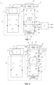
- connection means 19 may comprise a first three-way valve 20 which is adapted to connect the first 14 and the second 18 secondary circuits to the inlet 11A of the second thermal device 11, and a second three-way valve 21 configured for selective connection of the first 14 and of the second 18 secondary circuits to the outlet 11B of the second thermal device 11.
- the first three-way valve 20 is connected to the delivery branch 14' of the first secondary circuit 14 and to a delivery branch 18' of the second secondary circuit 18, whereas the second three-way valve 21 is connected to the return branch 14" of the first secondary circuit 14 and to a return branch 18" of the second secondary circuit 18.
- the means for connection 19 when the plant 1 operates in heating mode, the means for connection 19 will be configured to mix and adjust the flow of the first secondary fluid F2 with the second secondary fluid F3 to improve the operating efficiency of operation of the second thermal device 11.
- connection means 19 will be configured to stop the flow the first secondary fluid F2 and connect the second secondary circuit 18 to the inlet 11A and outlet 11B of the second thermal device 11.
- the heat pump 17 may be connected in series with the condenser 9 and the second heating device 11 and be interposed therebetween and may be in fluid communication with the first secondary circuit 14.
- the delivery branch 14' of the first secondary circuit 14 will be adapted to directly connect the outlet 15B of the second pipe 15 to a first inlet 17a of the heat pump 17 and the return branch 14" of the first secondary circuit 14 will be adapted to directly connect a first outlet 17b of the heat pump 17 to the inlet 15A of the second pipe 15.
- the delivery branch 18' of the second secondary circuit 18 will be adapted to connect the inlet 11A of the second thermal device 11 to a second outlet 17c of the heat pump 17, whereas the return branch 18" of the second secondary circuit 18 will be adapted to connect the outlet 11B of the second thermal device 11 to a second inlet 17D of the heat pump 17.
- connection means 19 may comprise one or more valves 22 located in the first secondary circuit 14 and configured to selectively connect the condenser 9 and the heat pump 17 when the latter is in the ambient heating mode.
- FIG. 2 shows a first secondary circuit 14 comprising a pair of valves 22 located at the delivery branch 14 and the return branch 14" respectively.
- the heat pump 17 may be connected to a high temperature source of thermal energy and the connection means 19 will be closed.
- the pumping means 16 may comprise a first pump 16 located in the return branch 14" of the first secondary circuit 14 and a second pump 16" located in the return branch 18" of the second secondary circuit 18.
- first 16' and second 16" pumps may be placed in the delivery branches 14', 18' of the first 14 and the second 18 secondary circuits respectively, as described for the first embodiment.
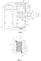
- the plant 1 may comprise a heat accumulator 23 in fluid communication with the first 14 and the second 18 secondary circuits and connected to the second thermal device 11 for conveying the accumulated fluid F4, heated or cooled by the heat pump 17 or heated by the condenser 9, toward the second thermal device 11.
- the delivery branch 14' of the first secondary circuit 14 will be adapted to directly connect the outlet 15B of the second pipe 15 to a first inlet 23A of the accumulator 23 and the return branch 14" of the first secondary circuit 14 will be adapted to directly connect a first outlet 23B of the accumulator 23 to the inlet 15A of the second pipe 15.
- the delivery branch 18' of the second secondary circuit 18 will be adapted to connect the outlet 17C of the heat pump 17 to a second inlet 23C of the accumulator 23, whereas the return branch 18" of the second secondary circuit 18 will be adapted to connect a second outlet 23D of the accumulator 23 to an inlet 17D of the heat pump 17.
- a third outlet 23e of the accumulator 23 may be connected to the inlet 11A of the second thermal device 11 via a delivery branch 24' of a third secondary circuit 24 whereas the outlet 11b of second thermal device 11 may be connected to a third inlet 23F of the accumulator 23 via a return branch 24" of the third secondary circuit 24.
- connection means 19 may comprise, for each secondary circuit 14, 18, at least two two-way valves 25, 26 for selectively connecting the condenser 9 or the heat pump 17 with the accumulator 23.
- the heat pump 17 connected to the accumulator 23, by operation of the fluid connection means 19 can afford cooling of the environment.
- the two-way valves 25 are closed, whereas the two-way valves 26 are open.
- the pumping means 16 may comprise a first pump 16 located in the return branch 14" of the first secondary circuit 14 and a second pump 16" located in the return branch 24" of the third secondary circuit 24.
- first 16' and second 16" pumps may be placed in the delivery branches 14', 24' of the first 14 and the third 24 secondary circuits respectively.
- a casing may be provided for enclosing two or more of the components of the plant 1, such as the first thermal device 2, the condenser 9, the heat pump 17, the accumulator 23 and the second heating device 11.
- a control unit 27 may be provided, which is connected to the control devices of the burner 3, the heat pump 17, the pumping means 16 and the connection means 19, to adjust the mixture percentages of the first 14 and second 18 secondary circuits as well as the temperature of the environment A.
- control unit 27 may be also connected to the accumulator 23, in the case of the embodiment as shown in FIG. 3 .
- the control unit 27 may be operably connected to a plurality of temperature sensors, not shown, for measuring the outside temperature, the temperature of the environment A and/or the temperature of the first F1 and/or of the first F2 and the second F3 secondary fluids and/or the accumulated fluid F4, in the case of the embodiment with the accumulator 23.
- control unit 27 may control the overall operation of the plant 1 according to the temperature measurements made at various points thereof and may calculate the total efficiency of the plant 1 according to energy consumption and the use of renewable energy sources.
- control unit 27 may stop fluid supply to the first 14 and/or of the second 18 secondary circuits in case of failure of the condenser 9 and the heat pump 17 respectively.
- ambient-air conditioning plant fulfils the intended objects and particularly affords efficient and uniform heating of an environment during the winter and cooling of the same environment during the summer.
- the present invention may find application in industry, because it can be produced on an industrial scale in factories operating in the field of ambient air-condition for civil or industrial use.
Landscapes
- Engineering & Computer Science (AREA)
- Chemical & Material Sciences (AREA)
- Combustion & Propulsion (AREA)
- Mechanical Engineering (AREA)
- General Engineering & Computer Science (AREA)
- Physics & Mathematics (AREA)
- Thermal Sciences (AREA)
- Life Sciences & Earth Sciences (AREA)
- Sustainable Development (AREA)
- Central Heating Systems (AREA)
- Other Air-Conditioning Systems (AREA)
Claims (10)
- Eine Hybridanlage (1) zur Klimatisierung einer Innenumgebung (A) für den zivilen oder industriellen Gebrauch, wobei die Anlage (1) umfasst:- mindestens eine erste thermische Vorrichtung (2), die einen Brenner (3) umfasst, der zum Erhitzen eines in einem geschlossenen Kreislauf (6) enthaltenen ersten Arbeitsfluid (F1) geeignet ist;- einen Schornstein (8) zum Ausstoßen der Verbrennungsprodukte (E) des Brenners (3);- mindestens eine zweite thermische Vorrichtung (11);- mindestens eine Wärmepumpe (17) mit einem zweiten Sekundärkreislauf (18), der ein zweites Sekundärfluid (F3) enthält und betriebsmäßig mit der zweiten thermischen Vorrichtung (11) verbunden ist;wobei der Kamin (8) einen Kondensator (9) zur zumindest teilweisen Rückgewinnung der fühlbaren und latenten Verdampfungswärme der Verbrennungsprodukte (E) umfasst;wobei der Kondensator (9) einen ersten Sekundärkreislauf (14) umfasst, der ein erstes Sekundärfluid (F2) enthält und betriebsmäßig mit der zweiten thermischen Vorrichtung (11) verbunden ist, um die zurückgewonnene Wärme mittels des ersten Sekundärfluids (F2) zumindest teilweise an die Umgebung (A) abzugeben;wobei der geschlossene Kreislauf (6) und der zweiten thermischen Vorrichtung (11) in derselben zu klimatisierenden Umgebung (A) angeordnet sind, wobei die Wärmepumpe (17) so angepasst ist, dass sie wahlweise im Heiz- oder Kühlmodus arbeitet, wobei Fluidverbindungsmittel (19) vorgesehen sind, um der zweiten thermischen Vorrichtung (11) wahlweise mit dem ersten Sekundärkreislauf (14) und/oder mit der Wärmepumpe (17) und dem Kondensator (9) zu verbinden, um die Umgebung (A) in Kombination mit dem ersten Wärmegerät (2) zu heizen, oder es zu trennen, um das Heizen der Umgebung (A) nur mittels des zweiten thermischen Vorrichtung (2) zu ermöglichen, wobei die Fluidverbindungsmittel (19) ferner so konfiguriert sind, dass sie der zweiten thermischen Vorrichtung (11) wahlweise über den Kreislauf (18) mit der Wärmepumpe (17) verbinden und es vom Kondensator (9) trennen, entweder um die Umgebung (A) zu kühlen oder um sie nur mittels der Wärmepumpe (17) zu heizen, wobei der geschlossene Kreislauf (6) fluidisch unabhängig von den ersten (14) und Sekundärkreislauf (18) ist.
- Anlage nach Anspruch 1, dadurch gekennzeichnet, dass die Verbindungsmittel (19) ein erstes Dreiwegeventil (20) umfassen, das dazu geeignet ist, den ersten (14) und/oder den zweiten (18) Sekundärkreislauf mit dem Einlass (11A) des zweiten thermischen Vorrichtung (11) zu verbinden oder davon zu trennen, und ein zweites Dreiwegeventil (21), das dazu geeignet ist, den ersten (14) und/oder den zweiten (18) Sekundärkreislauf mit dem Auslass (11B) des zweiten thermischen Vorrichtung (11) zu verbinden oder davon zu trennen.
- Anlage nach Anspruch 1, dadurch gekennzeichnet, dass die Wärmepumpe (17) dazu geeignet ist, in Reihe mit dem Kondensator (9) und der zweiten thermischen Vorrichtung (11) verbunden zu werden und strömungstechnisch mit dem ersten Sekundärkreislauf (14) verbunden ist.
- Anlage nach Anspruch 1, dadurch gekennzeichnet, dass die Verbindungsmittel (19) ein oder mehrere Ventile (22) umfassen, die sich im ersten Sekundärkreislauf (14) befinden und so konfiguriert sind, dass sie den Kondensator (9) und die Wärmepumpe (17) verbinden, wenn sich letztere im Umgebungsheizmodus befindet.
- Anlage nach Anspruch 1, dadurch gekennzeichnet, dass sie einen Wärmespeicher (23) umfasst, der in Flüssigkeitsverbindung mit dem ersten (14) und zweiten (18) Sekundärkreislauf steht und flüssigkeitsmäßig mit der zweiten thermischen Vorrichtung (11) verbunden ist, um die gesammelte Flüssigkeit (F4), die von der Wärmepumpe (17) erwärmt oder gekühlt oder von dem Kondensator (9) erwärmt wird, zu der zweiten thermischen Vorrichtung (11) zu befördern.
- Anlage nach Anspruch 5, dadurch gekennzeichnet, dass die Verbindungsmittel (19) für jeden Sekundärkreislauf (14, 18) mindestens zwei Zweiwegeventile (25, 26) zum Verbinden des Kondensators (9) und der Wärmepumpe (17) mit dem Speicher (23) umfassen.
- Anlage nach Anspruch 1, dadurch gekennzeichnet, dass die Wärmepumpe (17) eine Luft-Wasser-, Wasser-Wasser-, Luft-Luft- oder Wasser-Luft-Wärmepumpe ist.
- Anlage nach Anspruch 1, dadurch gekennzeichnet, dass der Kondensator (9) eine Wärmeaustauschkammer (10) umfasst, wobei der erste Sekundärkreislauf (14) ein zweites Rohr (15) umfasst, das in der Wärmeaustauschkammer (10) angeordnet ist, so dass die vom Brenner (3) erzeugten Verbrennungsprodukte (E) über seine Außenfläche fließen.
- Anlage nach Anspruch 1, dadurch gekennzeichnet, dass sie eine Steuereinheit (27) umfasst, die mit dem Brenner (3), der Wärmepumpe (17), den Pumpmitteln (16) und den Verbindungsmitteln (19, 19') verbunden ist, um die Temperatur der zu klimatisierenden Umgebung (A) einzustellen, wobei die Steuereinheit (27) betriebsmäßig mit einer Vielzahl von Temperatursensoren zum Messen der Temperatur der Umgebung (A) und/oder der Temperatur des Arbeitsfluids (F1) und/oder des ersten und zweiten Sekundärfluid (F2, F3) verbunden ist.
- Anlage nach Anspruch 9 in Kombination mit Anspruch, dadurch gekennzeichnet, dass die Steuereinheit mit dem Akkumulator (23) und mit einer Vielzahl von Temperatursensoren zum Messen der Außentemperatur und der Temperatur des angesammelten Fluids (F4) verbunden ist.
Applications Claiming Priority (2)
| Application Number | Priority Date | Filing Date | Title |
|---|---|---|---|
| IT201700136567 | 2017-11-28 | ||
| PCT/IB2018/059403 WO2019106560A1 (en) | 2017-11-28 | 2018-11-28 | Hybrid ambient-air conditioning for civil or industrial use |
Publications (3)
| Publication Number | Publication Date |
|---|---|
| EP3717837A1 EP3717837A1 (de) | 2020-10-07 |
| EP3717837C0 EP3717837C0 (de) | 2025-02-19 |
| EP3717837B1 true EP3717837B1 (de) | 2025-02-19 |
Family
ID=61581530
Family Applications (1)
| Application Number | Title | Priority Date | Filing Date |
|---|---|---|---|
| EP18829985.3A Active EP3717837B1 (de) | 2017-11-28 | 2018-11-28 | Hybrid-klimaanlage für zivil- oder industrielle umgebung |
Country Status (2)
| Country | Link |
|---|---|
| EP (1) | EP3717837B1 (de) |
| WO (1) | WO2019106560A1 (de) |
Citations (4)
| Publication number | Priority date | Publication date | Assignee | Title |
|---|---|---|---|---|
| DE202013010117U1 (de) * | 2013-11-08 | 2014-02-10 | Andreas Lang | Heizungsanlagen mit Abgaswärmenutzung |
| JP5580658B2 (ja) * | 2009-07-21 | 2014-08-27 | 大阪瓦斯株式会社 | 熱媒供給装置 |
| EP2937644A1 (de) * | 2014-04-22 | 2015-10-28 | Vaillant GmbH | Heizgerät mit wärmepumpe |
| EP3214377A1 (de) * | 2016-02-27 | 2017-09-06 | Wolfgang Jaske | Verfahren zum betrieb einer heizungsanlage mit einem brennwertkessel und heizungsanlage |
Family Cites Families (2)
| Publication number | Priority date | Publication date | Assignee | Title |
|---|---|---|---|---|
| US4409796A (en) * | 1982-03-05 | 1983-10-18 | Rutherford C. Lake, Jr. | Reversible cycle heating and cooling system |
| SE455880B (sv) * | 1982-04-14 | 1988-08-15 | Graenges Aluminium Ab | Vermeanleggning innefattande en vermepanna, vermepump, vermevexlare for att utvinna verme ur rokgas |
-
2018
- 2018-11-28 EP EP18829985.3A patent/EP3717837B1/de active Active
- 2018-11-28 WO PCT/IB2018/059403 patent/WO2019106560A1/en not_active Ceased
Patent Citations (4)
| Publication number | Priority date | Publication date | Assignee | Title |
|---|---|---|---|---|
| JP5580658B2 (ja) * | 2009-07-21 | 2014-08-27 | 大阪瓦斯株式会社 | 熱媒供給装置 |
| DE202013010117U1 (de) * | 2013-11-08 | 2014-02-10 | Andreas Lang | Heizungsanlagen mit Abgaswärmenutzung |
| EP2937644A1 (de) * | 2014-04-22 | 2015-10-28 | Vaillant GmbH | Heizgerät mit wärmepumpe |
| EP3214377A1 (de) * | 2016-02-27 | 2017-09-06 | Wolfgang Jaske | Verfahren zum betrieb einer heizungsanlage mit einem brennwertkessel und heizungsanlage |
Also Published As
| Publication number | Publication date |
|---|---|
| EP3717837A1 (de) | 2020-10-07 |
| EP3717837C0 (de) | 2025-02-19 |
| WO2019106560A1 (en) | 2019-06-06 |
Similar Documents
| Publication | Publication Date | Title |
|---|---|---|
| US7398778B2 (en) | Solar and heat pump powered electric forced hot air hydronic furnace | |
| US8397799B2 (en) | Automatic switching two pipe hydronic system | |
| US9605882B2 (en) | Heat pump with exhaust heat reclaim | |
| CA2839327C (en) | Hydronic air heater | |
| US20110259006A1 (en) | Versatile thermal solar system for producing hot water up to high temperatures | |
| EP3717837B1 (de) | Hybrid-klimaanlage für zivil- oder industrielle umgebung | |
| US7575001B2 (en) | Solar and heat pump powered electric forced hot air hydronic furnace | |
| ES2898888T3 (es) | Bomba de calor | |
| CN108645032B (zh) | 燃气炉 | |
| RU2604122C2 (ru) | Водогрейный котёл с встроенным тепловым насосом | |
| PL406309A1 (pl) | Układ urządzeń do pozyskiwania ciepłej wody z instalacji wody gruntowej dla urządzeń klimatyzacji i wentylacji | |
| JP2019190807A (ja) | 廃棄熱利用貯湯装置 | |
| ITPD20080073A1 (it) | Macchina ad assorbimento | |
| EP3327360B1 (de) | Kombinierte ausrüstung zur klimakontrolle von umgebungen | |
| KR100376220B1 (ko) | 보일러를 이용한 냉난방장치 | |
| EP2249090A2 (de) | Wärmesystem | |
| RU218421U1 (ru) | Гибридный настенный газово-электрический котел для поквартирного отопления | |
| US9683748B2 (en) | Rooftop hydronic heating unit | |
| CN104976815A (zh) | 一种高温热泵一体机 | |
| RU2544825C2 (ru) | Газовая теплонасосная установка | |
| CN222849445U (zh) | 空调机组和壁挂炉配合的联合制热控制系统 | |
| RU2782081C1 (ru) | Гибридный настенный газово-электрический котел | |
| ES1231070U (es) | Caldera eléctrica mixta para calefacción y/o ACS con aceite térmico | |
| RU2052177C1 (ru) | Тепловой агрегат | |
| TR2023010233A2 (tr) | Hem isitma hem de soğutma yapan bi̇r kombi̇ |
Legal Events
| Date | Code | Title | Description |
|---|---|---|---|
| STAA | Information on the status of an ep patent application or granted ep patent |
Free format text: STATUS: UNKNOWN |
|
| STAA | Information on the status of an ep patent application or granted ep patent |
Free format text: STATUS: THE INTERNATIONAL PUBLICATION HAS BEEN MADE |
|
| PUAI | Public reference made under article 153(3) epc to a published international application that has entered the european phase |
Free format text: ORIGINAL CODE: 0009012 |
|
| STAA | Information on the status of an ep patent application or granted ep patent |
Free format text: STATUS: REQUEST FOR EXAMINATION WAS MADE |
|
| 17P | Request for examination filed |
Effective date: 20200626 |
|
| AK | Designated contracting states |
Kind code of ref document: A1 Designated state(s): AL AT BE BG CH CY CZ DE DK EE ES FI FR GB GR HR HU IE IS IT LI LT LU LV MC MK MT NL NO PL PT RO RS SE SI SK SM TR |
|
| AX | Request for extension of the european patent |
Extension state: BA ME |
|
| DAV | Request for validation of the european patent (deleted) | ||
| DAX | Request for extension of the european patent (deleted) | ||
| STAA | Information on the status of an ep patent application or granted ep patent |
Free format text: STATUS: EXAMINATION IS IN PROGRESS |
|
| 17Q | First examination report despatched |
Effective date: 20220214 |
|
| GRAP | Despatch of communication of intention to grant a patent |
Free format text: ORIGINAL CODE: EPIDOSNIGR1 |
|
| STAA | Information on the status of an ep patent application or granted ep patent |
Free format text: STATUS: GRANT OF PATENT IS INTENDED |
|
| RIC1 | Information provided on ipc code assigned before grant |
Ipc: F24D 3/18 20060101ALI20240816BHEP Ipc: F24D 12/02 20060101ALI20240816BHEP Ipc: F24D 5/08 20060101ALI20240816BHEP Ipc: F24H 6/00 20060101ALI20240816BHEP Ipc: F24F 5/00 20060101AFI20240816BHEP |
|
| INTG | Intention to grant announced |
Effective date: 20240913 |
|
| GRAS | Grant fee paid |
Free format text: ORIGINAL CODE: EPIDOSNIGR3 |
|
| GRAA | (expected) grant |
Free format text: ORIGINAL CODE: 0009210 |
|
| STAA | Information on the status of an ep patent application or granted ep patent |
Free format text: STATUS: THE PATENT HAS BEEN GRANTED |
|
| AK | Designated contracting states |
Kind code of ref document: B1 Designated state(s): AL AT BE BG CH CY CZ DE DK EE ES FI FR GB GR HR HU IE IS IT LI LT LU LV MC MK MT NL NO PL PT RO RS SE SI SK SM TR |
|
| REG | Reference to a national code |
Ref country code: GB Ref legal event code: FG4D |
|
| REG | Reference to a national code |
Ref country code: CH Ref legal event code: EP |
|
| REG | Reference to a national code |
Ref country code: IE Ref legal event code: FG4D |
|
| REG | Reference to a national code |
Ref country code: DE Ref legal event code: R096 Ref document number: 602018079386 Country of ref document: DE |
|
| U01 | Request for unitary effect filed |
Effective date: 20250317 |
|
| U07 | Unitary effect registered |
Designated state(s): AT BE BG DE DK EE FI FR IT LT LU LV MT NL PT RO SE SI Effective date: 20250324 |
|
| PG25 | Lapsed in a contracting state [announced via postgrant information from national office to epo] |
Ref country code: RS Free format text: LAPSE BECAUSE OF FAILURE TO SUBMIT A TRANSLATION OF THE DESCRIPTION OR TO PAY THE FEE WITHIN THE PRESCRIBED TIME-LIMIT Effective date: 20250519 |
|
| PG25 | Lapsed in a contracting state [announced via postgrant information from national office to epo] |
Ref country code: PL Free format text: LAPSE BECAUSE OF FAILURE TO SUBMIT A TRANSLATION OF THE DESCRIPTION OR TO PAY THE FEE WITHIN THE PRESCRIBED TIME-LIMIT Effective date: 20250219 |
|
| PG25 | Lapsed in a contracting state [announced via postgrant information from national office to epo] |
Ref country code: ES Free format text: LAPSE BECAUSE OF FAILURE TO SUBMIT A TRANSLATION OF THE DESCRIPTION OR TO PAY THE FEE WITHIN THE PRESCRIBED TIME-LIMIT Effective date: 20250219 |
|
| PG25 | Lapsed in a contracting state [announced via postgrant information from national office to epo] |
Ref country code: NO Free format text: LAPSE BECAUSE OF FAILURE TO SUBMIT A TRANSLATION OF THE DESCRIPTION OR TO PAY THE FEE WITHIN THE PRESCRIBED TIME-LIMIT Effective date: 20250519 Ref country code: IS Free format text: LAPSE BECAUSE OF FAILURE TO SUBMIT A TRANSLATION OF THE DESCRIPTION OR TO PAY THE FEE WITHIN THE PRESCRIBED TIME-LIMIT Effective date: 20250619 |
|
| PG25 | Lapsed in a contracting state [announced via postgrant information from national office to epo] |
Ref country code: HR Free format text: LAPSE BECAUSE OF FAILURE TO SUBMIT A TRANSLATION OF THE DESCRIPTION OR TO PAY THE FEE WITHIN THE PRESCRIBED TIME-LIMIT Effective date: 20250219 |
|
| PG25 | Lapsed in a contracting state [announced via postgrant information from national office to epo] |
Ref country code: GR Free format text: LAPSE BECAUSE OF FAILURE TO SUBMIT A TRANSLATION OF THE DESCRIPTION OR TO PAY THE FEE WITHIN THE PRESCRIBED TIME-LIMIT Effective date: 20250520 |
|
| PG25 | Lapsed in a contracting state [announced via postgrant information from national office to epo] |
Ref country code: SM Free format text: LAPSE BECAUSE OF FAILURE TO SUBMIT A TRANSLATION OF THE DESCRIPTION OR TO PAY THE FEE WITHIN THE PRESCRIBED TIME-LIMIT Effective date: 20250219 |
|
| PG25 | Lapsed in a contracting state [announced via postgrant information from national office to epo] |
Ref country code: CZ Free format text: LAPSE BECAUSE OF FAILURE TO SUBMIT A TRANSLATION OF THE DESCRIPTION OR TO PAY THE FEE WITHIN THE PRESCRIBED TIME-LIMIT Effective date: 20250219 |
|
| PG25 | Lapsed in a contracting state [announced via postgrant information from national office to epo] |
Ref country code: SK Free format text: LAPSE BECAUSE OF FAILURE TO SUBMIT A TRANSLATION OF THE DESCRIPTION OR TO PAY THE FEE WITHIN THE PRESCRIBED TIME-LIMIT Effective date: 20250219 |
|
| PLBE | No opposition filed within time limit |
Free format text: ORIGINAL CODE: 0009261 |
|
| STAA | Information on the status of an ep patent application or granted ep patent |
Free format text: STATUS: NO OPPOSITION FILED WITHIN TIME LIMIT |
|
| U20 | Renewal fee for the european patent with unitary effect paid |
Year of fee payment: 8 Effective date: 20251126 |
|
| 26N | No opposition filed |
Effective date: 20251120 |