EP2249090A2 - Wärmesystem - Google Patents
Wärmesystem Download PDFInfo
- Publication number
- EP2249090A2 EP2249090A2 EP10004547A EP10004547A EP2249090A2 EP 2249090 A2 EP2249090 A2 EP 2249090A2 EP 10004547 A EP10004547 A EP 10004547A EP 10004547 A EP10004547 A EP 10004547A EP 2249090 A2 EP2249090 A2 EP 2249090A2
- Authority
- EP
- European Patent Office
- Prior art keywords
- media
- solar
- thermal energy
- thermal
- plant
- Prior art date
- Legal status (The legal status is an assumption and is not a legal conclusion. Google has not performed a legal analysis and makes no representation as to the accuracy of the status listed.)
- Withdrawn
Links
- XLYOFNOQVPJJNP-UHFFFAOYSA-N water Substances O XLYOFNOQVPJJNP-UHFFFAOYSA-N 0.000 claims abstract description 49
- 238000010438 heat treatment Methods 0.000 claims abstract description 42
- 230000003750 conditioning effect Effects 0.000 claims abstract description 37
- 239000012530 fluid Substances 0.000 claims abstract description 36
- 230000007613 environmental effect Effects 0.000 claims abstract description 25
- 238000004519 manufacturing process Methods 0.000 claims abstract description 18
- 238000001816 cooling Methods 0.000 claims description 21
- 238000000034 method Methods 0.000 claims description 4
- 230000004913 activation Effects 0.000 claims description 3
- 238000010792 warming Methods 0.000 claims description 2
- 235000019628 coolness Nutrition 0.000 claims 1
- 241000196324 Embryophyta Species 0.000 description 12
- 238000009826 distribution Methods 0.000 description 7
- 230000010354 integration Effects 0.000 description 7
- 238000003860 storage Methods 0.000 description 6
- 238000009434 installation Methods 0.000 description 4
- 230000005855 radiation Effects 0.000 description 4
- 239000012809 cooling fluid Substances 0.000 description 3
- LYCAIKOWRPUZTN-UHFFFAOYSA-N Ethylene glycol Chemical compound OCCO LYCAIKOWRPUZTN-UHFFFAOYSA-N 0.000 description 2
- 239000000203 mixture Substances 0.000 description 2
- 208000025174 PANDAS Diseases 0.000 description 1
- 208000021155 Paediatric autoimmune neuropsychiatric disorders associated with streptococcal infection Diseases 0.000 description 1
- 240000000220 Panda oleosa Species 0.000 description 1
- 235000016496 Panda oleosa Nutrition 0.000 description 1
- 239000006096 absorbing agent Substances 0.000 description 1
- WYTGDNHDOZPMIW-RCBQFDQVSA-N alstonine Natural products C1=CC2=C3C=CC=CC3=NC2=C2N1C[C@H]1[C@H](C)OC=C(C(=O)OC)[C@H]1C2 WYTGDNHDOZPMIW-RCBQFDQVSA-N 0.000 description 1
- 230000005540 biological transmission Effects 0.000 description 1
- 238000006243 chemical reaction Methods 0.000 description 1
- 238000007872 degassing Methods 0.000 description 1
- 230000005611 electricity Effects 0.000 description 1
- 230000002349 favourable effect Effects 0.000 description 1
- 239000002803 fossil fuel Substances 0.000 description 1
- 230000020169 heat generation Effects 0.000 description 1
- 238000005338 heat storage Methods 0.000 description 1
- 239000008236 heating water Substances 0.000 description 1
- WGCNASOHLSPBMP-UHFFFAOYSA-N hydroxyacetaldehyde Natural products OCC=O WGCNASOHLSPBMP-UHFFFAOYSA-N 0.000 description 1
- 238000012986 modification Methods 0.000 description 1
- 230000004048 modification Effects 0.000 description 1
- 238000011144 upstream manufacturing Methods 0.000 description 1
Images
Classifications
-
- F—MECHANICAL ENGINEERING; LIGHTING; HEATING; WEAPONS; BLASTING
- F24—HEATING; RANGES; VENTILATING
- F24D—DOMESTIC- OR SPACE-HEATING SYSTEMS, e.g. CENTRAL HEATING SYSTEMS; DOMESTIC HOT-WATER SUPPLY SYSTEMS; ELEMENTS OR COMPONENTS THEREFOR
- F24D11/00—Central heating systems using heat accumulated in storage masses
- F24D11/02—Central heating systems using heat accumulated in storage masses using heat pumps
- F24D11/0214—Central heating systems using heat accumulated in storage masses using heat pumps water heating system
- F24D11/0221—Central heating systems using heat accumulated in storage masses using heat pumps water heating system combined with solar energy
-
- F—MECHANICAL ENGINEERING; LIGHTING; HEATING; WEAPONS; BLASTING
- F24—HEATING; RANGES; VENTILATING
- F24D—DOMESTIC- OR SPACE-HEATING SYSTEMS, e.g. CENTRAL HEATING SYSTEMS; DOMESTIC HOT-WATER SUPPLY SYSTEMS; ELEMENTS OR COMPONENTS THEREFOR
- F24D2200/00—Heat sources or energy sources
- F24D2200/02—Photovoltaic energy
-
- F—MECHANICAL ENGINEERING; LIGHTING; HEATING; WEAPONS; BLASTING
- F24—HEATING; RANGES; VENTILATING
- F24D—DOMESTIC- OR SPACE-HEATING SYSTEMS, e.g. CENTRAL HEATING SYSTEMS; DOMESTIC HOT-WATER SUPPLY SYSTEMS; ELEMENTS OR COMPONENTS THEREFOR
- F24D2200/00—Heat sources or energy sources
- F24D2200/12—Heat pump
-
- F—MECHANICAL ENGINEERING; LIGHTING; HEATING; WEAPONS; BLASTING
- F24—HEATING; RANGES; VENTILATING
- F24D—DOMESTIC- OR SPACE-HEATING SYSTEMS, e.g. CENTRAL HEATING SYSTEMS; DOMESTIC HOT-WATER SUPPLY SYSTEMS; ELEMENTS OR COMPONENTS THEREFOR
- F24D2200/00—Heat sources or energy sources
- F24D2200/14—Solar energy
-
- F—MECHANICAL ENGINEERING; LIGHTING; HEATING; WEAPONS; BLASTING
- F24—HEATING; RANGES; VENTILATING
- F24D—DOMESTIC- OR SPACE-HEATING SYSTEMS, e.g. CENTRAL HEATING SYSTEMS; DOMESTIC HOT-WATER SUPPLY SYSTEMS; ELEMENTS OR COMPONENTS THEREFOR
- F24D2220/00—Components of central heating installations excluding heat sources
- F24D2220/08—Storage tanks
-
- Y—GENERAL TAGGING OF NEW TECHNOLOGICAL DEVELOPMENTS; GENERAL TAGGING OF CROSS-SECTIONAL TECHNOLOGIES SPANNING OVER SEVERAL SECTIONS OF THE IPC; TECHNICAL SUBJECTS COVERED BY FORMER USPC CROSS-REFERENCE ART COLLECTIONS [XRACs] AND DIGESTS
- Y02—TECHNOLOGIES OR APPLICATIONS FOR MITIGATION OR ADAPTATION AGAINST CLIMATE CHANGE
- Y02A—TECHNOLOGIES FOR ADAPTATION TO CLIMATE CHANGE
- Y02A30/00—Adapting or protecting infrastructure or their operation
- Y02A30/60—Planning or developing urban green infrastructure
-
- Y—GENERAL TAGGING OF NEW TECHNOLOGICAL DEVELOPMENTS; GENERAL TAGGING OF CROSS-SECTIONAL TECHNOLOGIES SPANNING OVER SEVERAL SECTIONS OF THE IPC; TECHNICAL SUBJECTS COVERED BY FORMER USPC CROSS-REFERENCE ART COLLECTIONS [XRACs] AND DIGESTS
- Y02—TECHNOLOGIES OR APPLICATIONS FOR MITIGATION OR ADAPTATION AGAINST CLIMATE CHANGE
- Y02B—CLIMATE CHANGE MITIGATION TECHNOLOGIES RELATED TO BUILDINGS, e.g. HOUSING, HOUSE APPLIANCES OR RELATED END-USER APPLICATIONS
- Y02B10/00—Integration of renewable energy sources in buildings
- Y02B10/20—Solar thermal
-
- Y—GENERAL TAGGING OF NEW TECHNOLOGICAL DEVELOPMENTS; GENERAL TAGGING OF CROSS-SECTIONAL TECHNOLOGIES SPANNING OVER SEVERAL SECTIONS OF THE IPC; TECHNICAL SUBJECTS COVERED BY FORMER USPC CROSS-REFERENCE ART COLLECTIONS [XRACs] AND DIGESTS
- Y02—TECHNOLOGIES OR APPLICATIONS FOR MITIGATION OR ADAPTATION AGAINST CLIMATE CHANGE
- Y02B—CLIMATE CHANGE MITIGATION TECHNOLOGIES RELATED TO BUILDINGS, e.g. HOUSING, HOUSE APPLIANCES OR RELATED END-USER APPLICATIONS
- Y02B10/00—Integration of renewable energy sources in buildings
- Y02B10/70—Hybrid systems, e.g. uninterruptible or back-up power supplies integrating renewable energies
Definitions
- the present discovery refers to a heat system for the conversion of solar energy into thermal energy and the production of domestic hot water and/or indoor heating and conditioning.
- the heat system according to the present discovery can be connected to other heating and/or conditioning sources and can be installed outdoor or indoor, in the so called technical room or any other suitable premises in a house or building.
- Solar systems for the production of thermal energy to warm up domestic hot water or a thermal carrier fluid in a heating plant are well known.
- Such known systems comprise several solar panels, arranged in a configuration exposed to solar radiation, like on the building roof, and connected to a line distributing a heat carrier fluid which is linked, directly or indirectly, either to the distribution of domestic hot water or to the distribution of the heating system.
- a typical drawback of such known systems is that, in particular during winter months or generally during days with few or null solar radiation, the solar boiler is unable to individually satisfy an average family's thermal energy needs. Moreover, known systems during summer months are unable to provide environmental cooling/conditioning.
- a purpose of the present discovery is to realize a thermal plant which can satisfy the user's thermal energy needs over the whole year, which can shorten the installation times of the distributing circuits of the heating plant avoiding the possible errors in such phase.
- a compact heat system according to the present discovery is employed to produce domestic hot water and at least for the environmental heating of a house or a building.
- the plant according to the present discovery comprises:
- the aforesaid solar panel media and generation media are able to simultaneously supply, according to defined or definable ratio, thermal energy to the solar boiler, so that the house or building thermal energy demand is met.
- the heat generation media comprise a heat pump, using which is possible, in a first operating condition, to integrate the generation of thermal energy in the solar boiler and, in a second operating condition, to provide for the environmental conditioning in a house or building by cooling a secondary fluid which is employed in the conditioning media for the cooling.
- the discovery comprises, as thermal energy generators, a gas burner or a fireplace as heat sources.
- the compact heat system comprises renewable electric energy generators which are able to directly or indirectly supply, or integrate, the electric feed for the operation of the thermal energy generators, so that the discovery is made independent from non renewable electric and thermal energy sources.
- the system simultaneously employing two renewable sources, thermal from the solar and electric from the photovoltaic, make the discovery advantageously autonomous from an energetic point of view.
- the renewable electric energy generation media include photovoltaic panels.
- the present discovery satisfies all the needs connected to the realization of compact solar plant for the generation of domestic hot water and environmental conditioning.
- the discovery automatically manages the energetic sources to which is connected together with the distribution system of domestic hot water and the environmental cooling/conditioning and heating circuit.
- the discovery allows the heat pump to work in cooling mode, excluding the thermal energy integrating circuit from the solar boiler" while the boiler itself can, anyway, contemporary continue its function of domestic hot water generation.
- This is particularly advantageous with respect to a known type of heat pump, which during summer time can alternatively works as environmental cooling device or domestic hot water heating device, but never in both modes contemporary.
- the heat pump doesn't work as cooler but as heater, and can be used as integration to the boiler thermal energy.
- the heat system includes temperature sensing media able to supply signals which are indicative of the temperature inside the solar boiler and/or at the inlet/outlet of solar panels or thermal conditioning media.
- the system advantageously includes control media which, depending also from the signals coming from aforesaid temperature sensing media, are able to control and command the operation of the solar panels together with the selective activation of the thermal energy generation media and of Thermal conditioning media.
- the aforesaid thermal conditioning media include radiant heating, advantageously employable for environmental cooling too.
- thermal conditioning media include thermal convectors.
- An advantageous variant of the present discovery provides a group for the automatic filling of the solar panels circuits with the heat carrier fluid.
- the assembly of the hydraulic and electronic components related to the heat pump, solar panel circuit, feeding and distribution of domestic hot water, environmental conditioning and electronic units is carried out directly in the factory. This allows to perform, already during the assembly, all the necessary tests in order to ensure the full operation of the system. Therefore the installation is highly simplified: it is only necessary to connect the pipes for domestic water, conditioning circuit (radiant heating or thermal convector), solar circuit and heat pump to the respective sleeves on the outer of the solar boiler to have the full operating system.
- a procedure according to the present discovery to produce domestic hot water and at least for environmental heating includes:
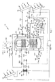
- a thermal plant 10 for a house or other building includes:
- the employed photovoltaic panels 18 have small size, i.e. 1 kWp.
- photovoltaic panels 18 it is possible to be disengaged from the use of fossil fuels or electric energy taken from the public distribution.
- the photovoltaic panels 18 can directly teed the heat pump 16, through batteries and accumulators. Or, the photovoltaic panels 18 can put the produced energy in the local electric energy dealer's grid, while this feed, when necessary, the heat pump 16. In any case the balance is favourable for the user.
- the storage in the solar boiler 12, for domestic hot water and heating, is heated by means of the solar panels 14 and the heat pump 16.
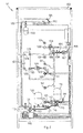
- the solar boiler 12 realized both for indoor and outdoor environments, is, in this case, a combined type, double layer enamelled with a double, fixed serpentine.
- Such solar boiler 12 see also in fig. 2 , holds and external careening 102, on which are realized the connections for the various fluids.
- the solar boiler 12 has a connection 134 for cold domestic water, depicted with CW1 in fig. 1 , where a check valve 20, an expansion vessel 132 and a safetyvalve 133 can be found in series.
- the solar boiler 12 has a second inlet for cold water, depicted as CW2 in fig. 1 , by which it is possible to operate the load of the solar boiler 12 (function of thermal fly wheel), which provides a load group 119, an expansion vessel 120, a stop valve 25 and a safety vale 27.
- the solar boiler 12 includes, moreover, an outlet 135 for domestic hot water, depicted with HW in fig. 1 .
- a recirculation for domestic hot water, depicted with R in fig. 1 is also provided.
- the solar boiler 12 has, in the upper part, a manual discharge duct 103 ( fig. 2 ).
- the solar panels 14 provide a return line 28, to allow the flow of the hear carrier fluid, i.e. a water/glycol mixture, from the solar boiler 12.
- the return line 28 to the solar panels 14 provide, in series, a thermometer 121 to detect the outlet temperature from the solar boiler 12, a stop valve 38, a solar circulator 113 for the transmission of the heat carrier fluid from the solar boiler 12 to the solar panels 14, and expansion vessel 112, for the expansion of the heat carrier fluid in the determined limits, a check valve 46 and a safety valve 114, to discharge the heat carrier fluid when it exceeds these limits when the temperatures in the solar circuit and in the storage are too high.
- the heat carrier fluid When the heat carrier fluid is discharged from the safety valve 114, it is collected in a tank 30, inlet 50, and afterwards taken from the tank 30, outlet 32, and inserted back again in the solar circuit by means of an automatic filling group 34.
- the reinsertion at the load tap 116 is automatically carried out by means of an autoclave 118 and an expansion chamber 33. Before reinsertion the heat carrier fluid flows through an automatic load group 117 which acts as pressure regulator, allowing to insert back the previously discharged fluid while maintaining the design pressure values. Moreover the solar circuit provides also a manual discharge duct 115.
- Temperature sensors 52, 54 are provided, in order to determine the temperature values in different positions in the solar boiler 12. Housing 131 for the sensors 52, 54 are also provided ( fig. 2 ).
- an outlet line 56 for the heat carrier fluid from the solar panels 14 to the solar boiler 12 in which one has, in series, a pressure gauge 111, a thermometer 122 to detect the outlet temperature to the solar circuit and a vent valve 123 to allow degassing before the heat carrier fluid enters the solar boiler 12.
- the radiant system 15, for underfloor heating, are integrated with a control and management unit for underfloor environmental conditioning, which comprises variable speed circulators, motorized mixing valve, control electronics, temperature and humidity sensors.
- the first line 76 is split in two sub-lines, of which a first one 80 enters the solar boiler 12 and a second one 82 is connected to a 3 way (2 inlet, 1 outlet) motorized mixing valve 109.
- the mixing valve 109 provides, other than the inlet from the line 82, also another inlet line 96, with a check valve 94 connected to the head of the solar boiler 12, for secondary cooling flow coming from the circuit of the heat pump 16 which will be better explained in the following.
- the outlet of the mixing valve 109 provides a gate valve 108, a temperature sensor 105 to detect the temperature at the outlet of the thermal conditioning, heating or cooling, and a circulator 107 to feed the radiant panel 15 circuit, through the inlet 84.
- the mixing valve 109 is properly adjusted for the desired flow of the secondary cooling fluid to have environmental cooling, always by means of radiant panels 15, while, during winter months, the mixing valve 109 allows only the flow of the heat carrier fluid coming from the solar boiler 12 for environmental heating.
- the heat pump 16 has, on one side, a circuit 62 for Freon, or another suitable gas, flow into a condenser/evaporator 127, with the purpose of heating water or to cool down a secondary fluid for environmental cooling.
- the heat pump 16 circuit provides on the water or fluid side, an outlet line 128 which is connected to a motorized 3 way deviating valve 104 (1 inlet, 2 outlets), by means of which it is made the switching between the circuit which integrates thermal energy in the solar boiler 12 and the circuit for environmental cooling.
- the two outlets from the deviating valve 104 are made from the line 96 which goes to the mixing valve 109 as already said, for the flow of the secondary cooling fluid, and from an outlet line 129 to put, via an integration inlet 130, hot integration water in the solar boiler 12, to aid the generation of the necessary thermal energy.
- the heat pump 16 circuit water side, provides moreover a pump 124 which sucks water from the solar boiler 12 and pump it, via an integration return line 125 and a check valve 72, to the evaporator/condenser 127, where it is heated.
- the check valve 72 Before the check valve 72, it is connected to the circuit the second line 78 coming from the deviating valve 74 and all goes into the evaporator/condenser 127, via a return line 126 of the heat pump.
- the second line 78 and the line 96 can be employed during summer months, when the heat pump 16 is used to cool down the secondary fluid for environmental cooling via the radiant panel 15.
- the deviating valves 74 and 104 are properly set, so that lines 125 and 129 of the integrating circuit are excluded and not employed, since normally during summer there is no need to integrate the thermal energy production in the solar boiler 12, and the secondary fluid cooled in the condenser/evaporator 127 can flow in the circuit connecting the radiant panels 15 through the lines 78 and 96.
- the operation of the system 10 is controlled and commanded from an electronic unit 106 with an electric cabinet.
- the discovery is fully equipped with electric wiring and switches.
- the unit 106 sends the commands for the activation of the solar panels 14 circuit, the heat pump 16, the radiant panels 15 for heating, according to the signals received from the various temperature sensors 52,54,105.
- the unit 106 is able to switch the heat pump 16 from the integration of thermal energy to the solar boiler 12, typically during winter months, to environmental cooling/conditioning, in summer months, acting on the deviating valves 74 and 104 for their above said operation.
- the unit 106 activates the heat pump 16, to integrate the heat energy supply to the solar boiler 12, particularly during winter months or during days with low solar irradiation.
- the heat pump 16 in this way, provide the thermal energy necessary to the integration of heating and domestic hot water production during the winter, and produces cooled water for environmental cooling/conditioning during the summer.
- the employed heat pump 16 can have a power of 34000 Btu/hr.
- the solar boiler 12 can have the following sizes:
- the plant 10 represents, then, a system completely factory assembled and compact. l.e. the ensemble of solar boiler 12 600/150, heat pump 16, radiant panel 15 control station and automatic filling group 34 has the following dimensions: height 2265 mm, width 1100 mm and depth 1465 mm.
- Thermal plant with a 600/150 boiler for a 120 m 2 apartment in B class (Epi: 40 kWh/m 2 per year), mean yearly consumption 6200 kWh.
- Such system can be coupled to 4 PANDA 2.6 collectors (net absorber surface 10 m 2 ).
- the plant assembled in such way can cover, with the solar panels, more than 60% of the necessity of a mean family for heating and domestic hot water.
- the heat pump integrates the system during winter months, when the solar circuit is not self-sufficient (it covers only the 40% of the need) and produces cooled water for environmental conditioning during summer.
- photovoltaic panels 18 meets the electric consumption of the heat pump, completely removing the energetic dependence of the apartment.
Landscapes
- Engineering & Computer Science (AREA)
- Mechanical Engineering (AREA)
- Life Sciences & Earth Sciences (AREA)
- Sustainable Energy (AREA)
- Physics & Mathematics (AREA)
- Thermal Sciences (AREA)
- Chemical & Material Sciences (AREA)
- Sustainable Development (AREA)
- General Engineering & Computer Science (AREA)
- Combustion & Propulsion (AREA)
- Steam Or Hot-Water Central Heating Systems (AREA)
- Photovoltaic Devices (AREA)
- Saccharide Compounds (AREA)
- Moving Of Heads (AREA)
- Computer And Data Communications (AREA)
- Heat-Pump Type And Storage Water Heaters (AREA)
Applications Claiming Priority (1)
| Application Number | Priority Date | Filing Date | Title |
|---|---|---|---|
| ITUD2009A000087A IT1394347B1 (it) | 2009-05-06 | 2009-05-06 | Impianto termico |
Publications (2)
| Publication Number | Publication Date |
|---|---|
| EP2249090A2 true EP2249090A2 (de) | 2010-11-10 |
| EP2249090A3 EP2249090A3 (de) | 2011-09-14 |
Family
ID=41508263
Family Applications (1)
| Application Number | Title | Priority Date | Filing Date |
|---|---|---|---|
| EP10004547A Withdrawn EP2249090A3 (de) | 2009-05-06 | 2010-04-30 | Wärmesystem |
Country Status (2)
| Country | Link |
|---|---|
| EP (1) | EP2249090A3 (de) |
| IT (1) | IT1394347B1 (de) |
Cited By (2)
| Publication number | Priority date | Publication date | Assignee | Title |
|---|---|---|---|---|
| ITPD20120146A1 (it) * | 2012-05-09 | 2013-11-10 | Espe S R L | Impianto per l'ottimizzazione dello sfruttamento dell'energia elettrica a disposizione di un edificio, e procedimento per l'impiego di tale impianto. |
| CN105091353A (zh) * | 2014-05-07 | 2015-11-25 | 银川艾尼工业科技开发有限公司 | 一种定温自动集热太阳能高温集热器 |
Family Cites Families (4)
| Publication number | Priority date | Publication date | Assignee | Title |
|---|---|---|---|---|
| DE2809425A1 (de) * | 1978-03-04 | 1979-09-06 | Happel Kg | Einrichtung zur deckung des waermebedarfs der waermeverbraucher eines gebaeudes |
| EP1674802A3 (de) * | 2004-12-21 | 2008-05-14 | Titano SA | Multifunktionale Zentrale für Heizung und/oder Kühlung in Wohnbauten |
| ITRM20050031U1 (it) * | 2005-03-11 | 2006-09-12 | Solari S R L Costruzioni | Bollitore solare perfezionato. |
| EP2141419A1 (de) * | 2008-07-04 | 2010-01-06 | Roth Werke GmbH | Gebäudeheiz- und/oder -kühlvorrichtung |
-
2009
- 2009-05-06 IT ITUD2009A000087A patent/IT1394347B1/it active
-
2010
- 2010-04-30 EP EP10004547A patent/EP2249090A3/de not_active Withdrawn
Cited By (2)
| Publication number | Priority date | Publication date | Assignee | Title |
|---|---|---|---|---|
| ITPD20120146A1 (it) * | 2012-05-09 | 2013-11-10 | Espe S R L | Impianto per l'ottimizzazione dello sfruttamento dell'energia elettrica a disposizione di un edificio, e procedimento per l'impiego di tale impianto. |
| CN105091353A (zh) * | 2014-05-07 | 2015-11-25 | 银川艾尼工业科技开发有限公司 | 一种定温自动集热太阳能高温集热器 |
Also Published As
| Publication number | Publication date |
|---|---|
| ITUD20090087A1 (it) | 2010-11-07 |
| IT1394347B1 (it) | 2012-06-06 |
| EP2249090A3 (de) | 2011-09-14 |
Similar Documents
| Publication | Publication Date | Title |
|---|---|---|
| RU2249125C1 (ru) | Система автономного электро- и теплоснабжения жилых и производственных помещений | |
| US8397799B2 (en) | Automatic switching two pipe hydronic system | |
| CA3003936C (en) | Heat pump network | |
| GB2474421A (en) | Thermostatically controlled mixing valve when connected with a high temperature source and a low temperature source | |
| AU2016275938A1 (en) | Hot water heating device having solar energy and off-peak electric heating energy storage and application | |
| RU85989U1 (ru) | Комбинированная система теплоснабжения | |
| AU2015223217A1 (en) | A hybrid supplemental solar energy collection and dissipation system with one or more heat pumps | |
| WO2022112661A1 (en) | A hybrid heating arrangement and a method of operating a hybrid heating arrangement | |
| AU2014275363B2 (en) | Integrated renewable energy system | |
| KR20050068288A (ko) | 가정용보일러와 연계한 태양열 급탕, 난방 시스템 | |
| EP2249090A2 (de) | Wärmesystem | |
| CN108224537A (zh) | 风光互补型智能供热供电系统 | |
| KR101026259B1 (ko) | 태양열 집열장치와 이를 이용한 온수 겸용 난방시스템 | |
| CN210197447U (zh) | 多能源互补的学校供暖节能系统 | |
| Sarbu et al. | Solar water and space heating systems | |
| CN201373489Y (zh) | 太阳能热水锅炉采暖设备 | |
| KR102009297B1 (ko) | 인공지능형 히트펌프 보일러 시스템 | |
| EP3611435A1 (de) | Heizsystem | |
| Dannemand et al. | Performance of a solar heating system with photovoltaic thermal hybrid collectors and heat pump | |
| CN217952439U (zh) | 太阳能及耗能辅热供热装置 | |
| RU48394U1 (ru) | Комбинированная автономная система теплоснабжения здания | |
| EP1159567A1 (de) | Heizanlage | |
| CN210832167U (zh) | 一种多能互补供热系统 | |
| CN101482344B (zh) | 中央空调系统 | |
| RU2013108493A (ru) | Система автономного электро- и теплоснабжения жилых и производственных помещений |
Legal Events
| Date | Code | Title | Description |
|---|---|---|---|
| PUAI | Public reference made under article 153(3) epc to a published international application that has entered the european phase |
Free format text: ORIGINAL CODE: 0009012 |
|
| AK | Designated contracting states |
Kind code of ref document: A2 Designated state(s): AT BE BG CH CY CZ DE DK EE ES FI FR GB GR HR HU IE IS IT LI LT LU LV MC MK MT NL NO PL PT RO SE SI SK SM TR |
|
| AX | Request for extension of the european patent |
Extension state: AL BA ME RS |
|
| PUAL | Search report despatched |
Free format text: ORIGINAL CODE: 0009013 |
|
| AK | Designated contracting states |
Kind code of ref document: A3 Designated state(s): AT BE BG CH CY CZ DE DK EE ES FI FR GB GR HR HU IE IS IT LI LT LU LV MC MK MT NL NO PL PT RO SE SI SK SM TR |
|
| AX | Request for extension of the european patent |
Extension state: AL BA ME RS |
|
| RIC1 | Information provided on ipc code assigned before grant |
Ipc: F24D 11/02 20060101AFI20110811BHEP |
|
| STAA | Information on the status of an ep patent application or granted ep patent |
Free format text: STATUS: THE APPLICATION IS DEEMED TO BE WITHDRAWN |
|
| 18D | Application deemed to be withdrawn |
Effective date: 20120315 |