EP3717350B1 - A canopy control system - Google Patents
A canopy control system Download PDFInfo
- Publication number
- EP3717350B1 EP3717350B1 EP18811626.3A EP18811626A EP3717350B1 EP 3717350 B1 EP3717350 B1 EP 3717350B1 EP 18811626 A EP18811626 A EP 18811626A EP 3717350 B1 EP3717350 B1 EP 3717350B1
- Authority
- EP
- European Patent Office
- Prior art keywords
- canopy
- vehicle
- yoke
- control system
- control
- Prior art date
- Legal status (The legal status is an assumption and is not a legal conclusion. Google has not performed a legal analysis and makes no representation as to the accuracy of the status listed.)
- Active
Links
Images



Classifications
-
- B—PERFORMING OPERATIONS; TRANSPORTING
- B64—AIRCRAFT; AVIATION; COSMONAUTICS
- B64C—AEROPLANES; HELICOPTERS
- B64C31/00—Aircraft intended to be sustained without power plant; Powered hang-glider-type aircraft; Microlight-type aircraft
- B64C31/028—Hang-glider-type aircraft; Microlight-type aircraft
- B64C31/036—Hang-glider-type aircraft; Microlight-type aircraft having parachute-type wing
-
- B—PERFORMING OPERATIONS; TRANSPORTING
- B64—AIRCRAFT; AVIATION; COSMONAUTICS
- B64D—EQUIPMENT FOR FITTING IN OR TO AIRCRAFT; FLIGHT SUITS; PARACHUTES; ARRANGEMENT OR MOUNTING OF POWER PLANTS OR PROPULSION TRANSMISSIONS IN AIRCRAFT
- B64D17/00—Parachutes
- B64D17/02—Canopy arrangement or construction
- B64D17/025—Canopy arrangement or construction for gliding chutes
-
- B—PERFORMING OPERATIONS; TRANSPORTING
- B64—AIRCRAFT; AVIATION; COSMONAUTICS
- B64U—UNMANNED AERIAL VEHICLES [UAV]; EQUIPMENT THEREFOR
- B64U10/00—Type of UAV
- B64U10/50—Glider-type UAVs, e.g. with parachute, parasail or kite
Definitions
- the present invention relates to a canopy control system, a canopy arrangement and a paramotor.
- Embodiments of the present invention provide for a stabilisation method for a powered parachute delivery system.
- Powered air vehicles using soft wings made of fabric are used for leisure activities and surveillance, and occasionally for air delivery.
- the low cost and high lift capability of the paramotor design make these vehicles particularly suitable as delivery vehicles, and their capability can be significantly enhanced by designing them to fly autonomously using a control and guidance system following a set of predetermined instructions and/or directed by a remote pilot.
- the most significant challenge for users operating an autonomous paramotor occurs when the vehicle is preparing for take-off.
- the wing needs to inflate and sit stably above the vehicle to ensure a successful and safe take-off.
- this can be achieved by situating the wing in the propeller air stream so that the wing inflates and is lifted above the vehicle in readiness for take-off.
- the wing can have a tendency to become unstable and be difficult to control. This can cause the wing to be blown (pushed) to one side, making take-off unstable, and causing the vehicle to veer.
- US4865274 discloses a passive control assembly for gliding device.
- ES2536853 discloses a method and device for automatic stability control of radio control paramotors (Machine-translation by Google Translate, not legally binding).
- DE19634017 discloses a parafoil aircraft.
- US2007/018051A1 discloses a parachute steering system.
- the present invention provides a canopy control system comprising:
- the present invention further provides a canopy control system, a canopy arrangement and a paramotor as claimed.
- embodiments of the present invention provide a system to control and stabilise the canopy during inflation and take-off.
- a paramotor 10 consists of a canopy 1 (also referred to as a wing or sail) and a ground vehicle 2.
- the vehicle 2 may be a tricycle, or take other forms.
- the vehicle 2 consists of a vehicle body and carries a propulsion unit 3 (which may comprise, for example, a propeller, jet or rockets).
- the vehicle further comprises an undercarriage 4 (e.g. skids, tracks or wheels), and the pilot and/or control system.
- the vehicle 2 In flight, the vehicle 2 is suspended from the canopy 1 by a network of lines 7 known as a line system 6. Conventionally, the vehicle 2 is suspended at a pair of attachment points (left and right) on the vehicle 2, or any number of attachment points. The line system 6 then branches up to the canopy 1.
- the lines 7 attach to the canopy 1 underside at attachment points arranged in rows across the span, from the leading edge 8A towards the trailing edge 8B. These attached points are often called A, B, C rows, indicated as A,B,C on Figure 1 .
- This arrangement allows the angle of attack and camber of the canopy 1 to be adjusted by changing the length of the lines 7 attached to one or more rows of lines.
- the branching pattern of the lines 7 is arranged so that the lines 7 originating at one row are brought together into a single line (called a "riser” 9) near the base of the line system 6 and close to the vehicle 2 where it can be adjusted.
- the line branching pattern of the line system 6 is arranged so that all the lines 7 from all the rows on the left side of the canopy 1 meet in the left set of risers 9, and all those from the right side meet in the right set of risers 9, allowing steering control by adjusting the lengths of the left and right sets of lines 7 asymmetrically.
- References herein to the line system 6 are generally referring to a system comprising both lines 7 and risers 9.
- the rearmost set of lines 7 (those connected to row c) is conventionally attached at or near the trailing edge 8B of the canopy 1 and are used to control the canopy 1 by distorting the canopy 1 by pulling down the trailing edge 8B, which slows the canopy 1 (and these lines 7 are therefore called brakes). To turn, the brakes are applied asymmetrically and the paramotor vehicle 2 rolls and yaws towards the brake that is pulled down.
- the paramotor 10 is controlled using the brakes, accelerator and throttle.
- the throttle controls the propulsion force (e.g. motor speed) and determines climb and sink rate.
- the accelerator controls the canopy's angle of attack by adjusting the risers/lines 9, 6 in such a way as to change the angle of attack and/or camber and/or reflex of the canopy 1 and therefore the speed of the vehicle 2.
- the brakes selectively distort the trailing edge 8B of the canopy 1.
- Symmetric brake application - i.e. pulling down the trailing edge 8B of the left 1A and right 1B sides of the canopy 1 equally - slows the canopy 1.
- Asymmetric brake application pulling down the trailing edge 8B of one side 1A, 1B more than the other 1B, 1A - turns the canopy 1.
- applying a brake on the right side 1A results in a turn to the right.
- Turning may alternatively or additionally be controlled by asymmetric adjustment of the accelerator system.
- the paramotor 10 can also be controlled in roll and yaw by moving the centre of gravity of the ground vehicle 2 laterally, this imparts a turn towards the loaded side. Moving the centre of gravity towards the right will result in a turn to the right.
- the paramotor 10 may be controlled by a pilot onboard, and/or by remote control (for example using a radio control system and servos), or by an onboard autopilot, for example using an inertial measurement unit to identify attitude and heading and/or a GPS and/or a computer vision system to identify track and speed and command adjustment of the brakes, throttle and accelerator so as to execute the required flight path.
- a pilot onboard for example using a radio control system and servos
- an onboard autopilot for example using an inertial measurement unit to identify attitude and heading and/or a GPS and/or a computer vision system to identify track and speed and command adjustment of the brakes, throttle and accelerator so as to execute the required flight path.
- the canopy 1 is laid out on the ground, behind the vehicle 2, preferably aligned so that the take-off run is straight into any prevailing breeze.
- the vehicle 2 then accelerates and the canopy 1 rises under aerodynamic forces until it is above the vehicle 2.
- the vehicle 2 then continues to accelerate until the canopy aerodynamic lift exceeds vehicle weight at which point the vehicle 2 takes off and climbs out.
- a canopy control system embodying the present invention can therefore remain 'active' at all times, even though it will only be needed during takeoff. In one embodiment, there is no requirement to disengage or otherwise prevent the operation of the canopy control system during flight.
- the present invention provides means of controlling the canopy 1 during this inflation and/or take-off phase.
- the invention comprises a mechanical yoke 5 pivotably connecting the canopy to the vehicle 2.
- a canopy control system uses the motion of the yoke 5 relative to the vehicle 2 to impart control movements to the canopy 1 via a control mechanism to generate restoring forces to counteract any asymmetric motion of the canopy 1 or misalignment of the canopy relative to the vehicle 2 while the vehicle 2 is stationary in high wind before take-off and during the take-off run.
- the invention comprises a system where the canopy lines 6 and/or risers 9 attach to a mechanical yoke 5 pivotably connected to the vehicle 2.
- the control system further comprises a vehicle mounting 15, which is connected to the vehicle 2.
- the yoke is pivotably securable to the vehicle directly.
- the vehicle mounting 15 is not essential.
- the yoke is preferably above the pivot point.
- the pivot point is preferably connected to the vehicle 2 above the centre of gravity of the vehicle 2, so that the vehicle 2 hangs in an orientation that is substantially the same as its orientation in flight.
- the yoke extends laterally relative to the pivot point.
- the yoke 105 extends both laterally and in a fore-and-aft direction relative to the pivot point.
- the yoke 105 takes the general form of a plate.
- the lines 7 attach directly to the yoke 5, and the lines are distributed across the yoke 5 so that the outermost lines on the canopy are attached at the outermost attachment points on the yoke.
- the lines 7 attach directly to the yoke 205 (i.e. with no riser 9), and the lines 7 are distributed laterally and fore and aft on the yoke 205 so that the lines 7 connecting to the outermost attachment points on the canopy 1 are connected to the outermost points on the yoke.
- the A lines 7 attach at the front of the yoke 205, the B and C lines 7 further back.
- the canopy 1 tip lines attach at the outer extremes of the yoke 205 while the central lines 7 attach at the centre of the yoke 205.
- the yoke 205 takes the form of a plate.
- the risers 9 attach to the yoke 5, with the left riser 9 attaching to the left side of the yoke 5 and the right riser 9 to the right side of the yoke 5.
- This configuration provides lateral control of the canopy 1.
- the risers 9 also split fore and aft so that there is one riser 9 for each row of lines, and for each side of the canopy 1.
- the left A riser attaches at the front left of the yoke
- the B, C etc. risers 9 attach further back on the yoke 305 on their respective sides.
- attaching the canopy 1 to the pivotably attached yoke 5, 105, 205, 305 means that during launch the yoke 5, 105, 205, 305 follows the motion of the canopy 1, as the canopy 1 rises from the initial launch position on the ground to the flight position above the vehicle 2.
- Embodiments of the present invention effectively use the motion of the yoke 5, 105, 205, 305 relative to the vehicle 2 to impart control movements to the canopy 1 to generate restoring forces to counteract any asymmetric motion or misalignment of the canopy 1 relative to the ground vehicle 2 during the take-off run.
- the orientation (angle) of the yoke 5, 105, 205, 305 relative to the vehicle 2 is measured using mechanical, hydraulic, electromagnetic or inertial sensors, and if that orientation differs from the flight orientation, the measured difference in orientation can be translated mechanically, hydraulically or electromagnetically, or through an autopilot system, into a control input to the canopy that provides a restoring force of appropriate magnitude and direction to return the canopy 1 and the yoke 5, 105, 205, 305 to the flight orientation.
- the invention uses a block and tackle 20 between each of the ends of the yoke 5 and the corresponding sides of the vehicle 2 to amplify the change in distance between those points.
- a misalignment of the canopy 1 with the vehicle 2 causes the yoke 5 to pivot relative to the vehicle 2 it changes the distance between the ends of the yoke 5 and the sides of the vehicle 2.
- the line through the block and tackle 20 is connected directly to a brake-line that runs to the outer sections of the trailing edge 8b of the canopy 1, so that the line 7 is under minimal tension when the canopy 1 is in the normal flight position relative to the vehicle 2. If the canopy 1 rises asymmetrically the yoke 5 will tip asymmetrically due to its connection to the canopy 1. On one side, the distance between the outer arm of the mechanical yoke 5 and the vehicle body 2 will increase, lengthening the block and tackle 20, and correspondingly shortening the length of the attached brake line by an amount amplified by the arrangement of the block and tackle 20.
- the block and tackle 20 is connected between the yoke 5 and the vehicle 2.
- the block and tackle 20 is connected between the yoke 5 and a vehicle mounting 15. The operation is substantially the same.
- a third block and tackle set 30 is attached between the front of the yoke 5 and the vehicle 2 body so that it acts to apply the accelerator when the yoke 5 is pivoted aft of the normal flight orientation (as it is at the start of the launch procedure).
- This fore -and-aft arrangement provides pitch stability in take-off, and the combination of both fore-and-aft and lateral arrangements provide stability in yaw, pitch and roll.
- a fourth set of block 40 and tackle is attached at the rear of the yoke 5 and acts to shorten the rear risers or the central brake lines if the yoke is pivoted forwards of the normal flight orientation, providing further pitch stability.
- electronic or electromagnetic position encoders are attached to the yoke and sense the movement of the yoke relative to the vehicle body. These movements are translated into signals transmitted to the vehicle autopilot, which is programmed to respond by commanding electromechanical devices to apply appropriate control inputs to restore the canopy to flight orientation.
- the control mechanism of an embodiment of the present invention may be connected to the brake line and/or riser of the line system 6, or may be connected to a separate line which, in turn, is connected to the wing tp.
- the control mechanism of an embodiment of the present invention may be auxiliary to the existing line system, or may be retrofit to the existing line system.
Landscapes
- Engineering & Computer Science (AREA)
- Aviation & Aerospace Engineering (AREA)
- Remote Sensing (AREA)
- Mechanical Engineering (AREA)
- Body Structure For Vehicles (AREA)
Description
- The present invention relates to a canopy control system, a canopy arrangement and a paramotor. Embodiments of the present invention provide for a stabilisation method for a powered parachute delivery system.
- Powered air vehicles using soft wings made of fabric, generally known as paramotors, are used for leisure activities and surveillance, and occasionally for air delivery. The low cost and high lift capability of the paramotor design make these vehicles particularly suitable as delivery vehicles, and their capability can be significantly enhanced by designing them to fly autonomously using a control and guidance system following a set of predetermined instructions and/or directed by a remote pilot.
- The most significant challenge for users operating an autonomous paramotor occurs when the vehicle is preparing for take-off. During take-off, the wing needs to inflate and sit stably above the vehicle to ensure a successful and safe take-off. Where there is substantially no prevailing wind, (i.e. still conditions), this can be achieved by situating the wing in the propeller air stream so that the wing inflates and is lifted above the vehicle in readiness for take-off. However, in windy, turbulent or cross wind conditions, the wing can have a tendency to become unstable and be difficult to control. This can cause the wing to be blown (pushed) to one side, making take-off unstable, and causing the vehicle to veer.
-
US4865274 discloses a passive control assembly for gliding device.ES2536853 DE19634017 discloses a parafoil aircraft.US2007/018051A1 discloses a parachute steering system. - In an embodiment, the present invention provides a canopy control system comprising:
- a yoke, comprising a plate and an angle sensor to detect the angle of the yoke with respect to a vehicle, configured to be pivotably securable to the vehicle and securable to a line system of a canopy, the line system secured to the plate via securing points distributed laterally and fore and aft on the plate in use, such that the yoke pivots with respect to the vehicle in a first direction when the canopy is subjected to a wind force; and
- a control mechanism configured to apply a control force to the canopy line system to cause the canopy to oppose the wind force, such that the yoke pivots with respect to the vehicle in a second direction which is opposite to the first direction.
- The present invention further provides a canopy control system, a canopy arrangement and a paramotor as claimed.
- Embodiments of the present invention will now be described, by way of non-limiting example only, with reference to the accompanying figures, in which:
-
FIGURE 1 illustrates a paramotor incorporating a canopy control system; -
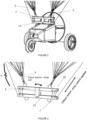
FIGURE 2 is an enlarged view of the vehicle and yoke of a canopy control system; -
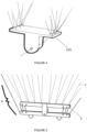
FIGURE 3 is an enlarged view of the yoke of a canopy control system; -
FIGURE 4 illustrates an alternative form and configuration of the yoke of a canopy control system embodying the present invention; -
FIGURE 5 illustrates an alternative form and configuration of the yoke of a canopy control system; -
FIGURE 6 illustrates an alternative form and configuration of the yoke of a canopy control system embodying the present invention; -
FIGURE 7 illustrates an alternative form and configuration of the yoke of a canopy control system; -
FIGURE 8 illustrates an alternative form and configuration of the yoke of a canopy control system embodying the present invention; -
FIGURES 9 - 11 illustrate alternative forms and configurations of the yoke of a canopy control system; - Generally, embodiments of the present invention provide a system to control and stabilise the canopy during inflation and take-off.
- With reference to
figure 1 , aparamotor 10 consists of a canopy 1 (also referred to as a wing or sail) and aground vehicle 2. Thevehicle 2 may be a tricycle, or take other forms. Thevehicle 2 consists of a vehicle body and carries a propulsion unit 3 (which may comprise, for example, a propeller, jet or rockets). The vehicle further comprises an undercarriage 4 (e.g. skids, tracks or wheels), and the pilot and/or control system. - In flight, the
vehicle 2 is suspended from thecanopy 1 by a network oflines 7 known as aline system 6. Conventionally, thevehicle 2 is suspended at a pair of attachment points (left and right) on thevehicle 2, or any number of attachment points. Theline system 6 then branches up to thecanopy 1. - Conventionally, the
lines 7 attach to thecanopy 1 underside at attachment points arranged in rows across the span, from the leadingedge 8A towards thetrailing edge 8B. These attached points are often called A, B, C rows, indicated as A,B,C onFigure 1 . This arrangement allows the angle of attack and camber of thecanopy 1 to be adjusted by changing the length of thelines 7 attached to one or more rows of lines. To facilitate this control the branching pattern of thelines 7 is arranged so that thelines 7 originating at one row are brought together into a single line (called a "riser" 9) near the base of theline system 6 and close to thevehicle 2 where it can be adjusted. - Conventionally, the line branching pattern of the
line system 6 is arranged so that all thelines 7 from all the rows on the left side of thecanopy 1 meet in the left set ofrisers 9, and all those from the right side meet in the right set ofrisers 9, allowing steering control by adjusting the lengths of the left and right sets oflines 7 asymmetrically. References herein to theline system 6 are generally referring to a system comprising bothlines 7 andrisers 9. - The rearmost set of lines 7 (those connected to row c) is conventionally attached at or near the
trailing edge 8B of thecanopy 1 and are used to control thecanopy 1 by distorting thecanopy 1 by pulling down thetrailing edge 8B, which slows the canopy 1 (and theselines 7 are therefore called brakes). To turn, the brakes are applied asymmetrically and theparamotor vehicle 2 rolls and yaws towards the brake that is pulled down. - In flight, the
paramotor 10 is controlled using the brakes, accelerator and throttle. The throttle controls the propulsion force (e.g. motor speed) and determines climb and sink rate. The accelerator controls the canopy's angle of attack by adjusting the risers/lines canopy 1 and therefore the speed of thevehicle 2. The brakes selectively distort thetrailing edge 8B of thecanopy 1. Symmetric brake application - i.e. pulling down thetrailing edge 8B of the left 1A and right 1B sides of thecanopy 1 equally - slows thecanopy 1. Asymmetric brake application - pulling down thetrailing edge 8B of oneside 1A, 1B more than the other 1B, 1A - turns thecanopy 1. For example, applying a brake on the right side 1A results in a turn to the right. Turning may alternatively or additionally be controlled by asymmetric adjustment of the accelerator system. - The
paramotor 10 can also be controlled in roll and yaw by moving the centre of gravity of theground vehicle 2 laterally, this imparts a turn towards the loaded side. Moving the centre of gravity towards the right will result in a turn to the right. - The
paramotor 10 may be controlled by a pilot onboard, and/or by remote control (for example using a radio control system and servos), or by an onboard autopilot, for example using an inertial measurement unit to identify attitude and heading and/or a GPS and/or a computer vision system to identify track and speed and command adjustment of the brakes, throttle and accelerator so as to execute the required flight path. - During take-off when there is minimal prevailing wind or substantially still air, the
canopy 1 is laid out on the ground, behind thevehicle 2, preferably aligned so that the take-off run is straight into any prevailing breeze. Thevehicle 2 then accelerates and thecanopy 1 rises under aerodynamic forces until it is above thevehicle 2. Thevehicle 2 then continues to accelerate until the canopy aerodynamic lift exceeds vehicle weight at which point thevehicle 2 takes off and climbs out. - It is widely recognised that the most difficult part of the take-off procedure is the phase where the
canopy 1 rises from the ground. If thecanopy 1 rises asymmetrically off to one side, then side forces may be produced that are directed to that side and can cause thecanopy 1 to collapse to the ground again, or can drag thevehicle 2 to that side, perhaps even overturning it. This problem is exacerbated during windy conditions, when thecanopy 1 rises above thevehicle 2 while thevehicle 2 is stationary before take-off, and can move uncontrollably from side to side. When a paraglider (a pilot having a similar canopy attached to their body) encounters such unbalancing forces during the takeoff procedure, they will typically overcome the effect by moving to the side. However,paramotor vehicles 2 are generally not able to move sideways in this manner, nor at the speed required to oppose or overcome any unbalancing forces. - In flight, the pivoting of the
yoke 5 with respect to the vehicle is unlikely to occur, since theparamotor 10 has pendulum stability in flight. A canopy control system embodying the present invention can therefore remain 'active' at all times, even though it will only be needed during takeoff. In one embodiment, there is no requirement to disengage or otherwise prevent the operation of the canopy control system during flight. - The present invention provides means of controlling the
canopy 1 during this inflation and/or take-off phase. The invention comprises amechanical yoke 5 pivotably connecting the canopy to thevehicle 2. A canopy control system according to the claims uses the motion of theyoke 5 relative to thevehicle 2 to impart control movements to thecanopy 1 via a control mechanism to generate restoring forces to counteract any asymmetric motion of thecanopy 1 or misalignment of the canopy relative to thevehicle 2 while thevehicle 2 is stationary in high wind before take-off and during the take-off run. - In one embodiment as outlined in
Figure 2 and 3 the invention comprises a system where thecanopy lines 6 and/orrisers 9 attach to amechanical yoke 5 pivotably connected to thevehicle 2. In the embodiment shown, the control system further comprises a vehicle mounting 15, which is connected to thevehicle 2. In other embodiments, such as those shown infigures 6 ,8 ,9 ,10 or 11 , the yoke is pivotably securable to the vehicle directly. The vehicle mounting 15 is not essential. - The yoke is preferably above the pivot point. The pivot point is preferably connected to the
vehicle 2 above the centre of gravity of thevehicle 2, so that thevehicle 2 hangs in an orientation that is substantially the same as its orientation in flight. In this embodiment the yoke extends laterally relative to the pivot point. - As shown in
figure 4 theyoke 105 extends both laterally and in a fore-and-aft direction relative to the pivot point. Theyoke 105 takes the general form of a plate. - In another embodiment (
figure 5 ), thelines 7 attach directly to theyoke 5, and the lines are distributed across theyoke 5 so that the outermost lines on the canopy are attached at the outermost attachment points on the yoke. - In another embodiment (
figure 6 ), thelines 7 attach directly to the yoke 205 (i.e. with no riser 9), and thelines 7 are distributed laterally and fore and aft on theyoke 205 so that thelines 7 connecting to the outermost attachment points on thecanopy 1 are connected to the outermost points on the yoke. Thus theA lines 7 attach at the front of theyoke 205, the B andC lines 7 further back. Similarly thecanopy 1 tip lines attach at the outer extremes of theyoke 205 while thecentral lines 7 attach at the centre of theyoke 205. Theyoke 205 takes the form of a plate. - In another embodiment (
figure 7 ) therisers 9 attach to theyoke 5, with theleft riser 9 attaching to the left side of theyoke 5 and theright riser 9 to the right side of theyoke 5. This configuration provides lateral control of thecanopy 1. - In another embodiment (
figure 8 ), therisers 9 also split fore and aft so that there is oneriser 9 for each row of lines, and for each side of thecanopy 1. For this embodiment the left A riser attaches at the front left of the yoke, theright A riser 9 at the front right of theyoke 305, and the B, C etc.risers 9 attach further back on theyoke 305 on their respective sides. - In each of these embodiments attaching the
canopy 1 to the pivotably attachedyoke yoke canopy 1, as thecanopy 1 rises from the initial launch position on the ground to the flight position above thevehicle 2. - Embodiments of the present invention effectively use the motion of the
yoke vehicle 2 to impart control movements to thecanopy 1 to generate restoring forces to counteract any asymmetric motion or misalignment of thecanopy 1 relative to theground vehicle 2 during the take-off run. The orientation (angle) of theyoke vehicle 2 is measured using mechanical, hydraulic, electromagnetic or inertial sensors, and if that orientation differs from the flight orientation, the measured difference in orientation can be translated mechanically, hydraulically or electromagnetically, or through an autopilot system, into a control input to the canopy that provides a restoring force of appropriate magnitude and direction to return thecanopy 1 and theyoke - In one embodiment (
figure 9 ) the invention uses a block and tackle 20 between each of the ends of theyoke 5 and the corresponding sides of thevehicle 2 to amplify the change in distance between those points. When a misalignment of thecanopy 1 with thevehicle 2 causes theyoke 5 to pivot relative to thevehicle 2 it changes the distance between the ends of theyoke 5 and the sides of thevehicle 2. - In this embodiment, the line through the block and tackle 20 is connected directly to a brake-line that runs to the outer sections of the trailing edge 8b of the
canopy 1, so that theline 7 is under minimal tension when thecanopy 1 is in the normal flight position relative to thevehicle 2. If thecanopy 1 rises asymmetrically theyoke 5 will tip asymmetrically due to its connection to thecanopy 1. On one side, the distance between the outer arm of themechanical yoke 5 and thevehicle body 2 will increase, lengthening the block and tackle 20, and correspondingly shortening the length of the attached brake line by an amount amplified by the arrangement of the block and tackle 20. This in turn applies a brake to the wing of thecanopy 1 that has risen higher, which provides a control input that counteracts the side force generated by the asymmetric orientation of the canopy. Simultaneously, the block and tackle 20 on the opposite side of theyoke 5 shortens, releasing the brake on that side, and this lateral arrangement ensures that thevehicle 2 is has roll and yaw stability in take-off, and thecanopy 1 becomes aligned and remains aligned above the vehicle in the flight orientation during the take-off run. - In the embodiment in
Figure 9 , the block and tackle 20 is connected between theyoke 5 and thevehicle 2. In the embodiment shown infigures 1 to 3 , the block and tackle 20 is connected between theyoke 5 and a vehicle mounting 15. The operation is substantially the same. - In an extension of this embodiment (
figure 10 ), a third block and tackle set 30 is attached between the front of theyoke 5 and thevehicle 2 body so that it acts to apply the accelerator when theyoke 5 is pivoted aft of the normal flight orientation (as it is at the start of the launch procedure). This fore -and-aft arrangement provides pitch stability in take-off, and the combination of both fore-and-aft and lateral arrangements provide stability in yaw, pitch and roll. - In a further extension of this embodiment (
figure 11 ) a fourth set ofblock 40 and tackle is attached at the rear of theyoke 5 and acts to shorten the rear risers or the central brake lines if the yoke is pivoted forwards of the normal flight orientation, providing further pitch stability. - Other embodiments of the invention are envisaged. The arrangement above described by block and tackle arrangement could also be achieved by a system of levers, gears, and/or a hydraulic system to give a purely mechanical control system.
- In another embodiment (not shown) electronic or electromagnetic position encoders are attached to the yoke and sense the movement of the yoke relative to the vehicle body. These movements are translated into signals transmitted to the vehicle autopilot, which is programmed to respond by commanding electromechanical devices to apply appropriate control inputs to restore the canopy to flight orientation.
- The control mechanism of an embodiment of the present invention may be connected to the brake line and/or riser of the
line system 6, or may be connected to a separate line which, in turn, is connected to the wing tp. In other words, the control mechanism of an embodiment of the present invention may be auxiliary to the existing line system, or may be retrofit to the existing line system. - When used in this specification and claims, the terms "comprises" and "comprising" and variations thereof mean that the specified features, steps or integers are included. The terms are not to be interpreted to exclude the presence of other features, steps or components.
Claims (14)
- A canopy control system comprising:a yoke (5), comprising a plate and an angle sensor to detect the angle of the yoke with respect to a vehicle, configured to be pivotably securable to the vehicle (2) and securable to a line system (6) of a canopy (1), the line system (6) securable to the plate via securing points distributed laterally and fore and aft on the plate in use, such that the yoke (5) pivots with respect to the vehicle (2) in a first direction when the canopy (1) is subjected to a wind force; anda control mechanism configured to apply a control force to the canopy line system (6) to cause the canopy (1) to oppose the wind force, such that the yoke (5) pivots with respect to the vehicle (2) in a second direction which is opposite to the first direction.
- A canopy control system according to claim 1, wherein the yoke (5) is configured to pivot laterally with respect to the longitudinal axis of the vehicle (2).
- A canopy control system according to claim 1, wherein the yoke (5) is configured to pivot parallel to the longitudinal axis of the vehicle (2).
- A canopy control system according to claim 1, wherein the yoke (5) is configured to pivot both laterally with respect to the longitudinal axis of the vehicle (2) and parallel to the longitudinal axis of the vehicle (2).
- A canopy control system according to any preceding claim, wherein the yoke (5) is substantially elongate.
- A canopy control system according to any preceding claim, wherein the control system is configured to selectively apply a control force to at least part of the trailing edge (8B) of the canopy (1).
- A canopy control system according to any preceding claim, further comprising a mounting (15) for connection to a vehicle (2), wherein the yoke (5) is pivotably secured to the mounting (15).
- A canopy control system according to any preceding claim, wherein the control mechanism comprises a control line securable at one end to one of the yoke (5) and vehicle (2), and securable at the other end to the canopy (1), the control line passable through at least one pulley associated with at least the other of the vehicle (2) and yoke (5).
- A canopy arrangement comprising:a canopy (1) comprising an aerofoil;a line system (6) associated with the canopy (1); anda canopy control system according to any preceding claim.
- A canopy arrangement according to claim 9, wherein the line system (6) comprises sets of adjustment lines, each set of adjustment lines connected to a selected region of the canopy (1) to adjust the geometry of a canopy surface.
- A canopy arrangement according to claim 9 or 10, wherein the line system (6) comprises at least one riser (9), connected at one end to the yoke (5) and connected at the other end to one or more lines.
- A canopy arrangement according to any of claims 9 to 11, wherein the line system (6) is configured to adjust the geometry of a canopy surface asymmetrically.
- A paramotor comprising:a vehicle (2); anda canopy arrangement according to any of claims 9 to 12, wherein the yoke (5) is pivotably secured to the vehicle.
- A paramotor according to claim 13, wherein the yoke (5) is pivotably secured to the vehicle (2) at a point higher than the centre of gravity of the vehicle (2).
Applications Claiming Priority (2)
| Application Number | Priority Date | Filing Date | Title |
|---|---|---|---|
| GB1719858.1A GB2568897B (en) | 2017-11-29 | 2017-11-29 | A canopy control system |
| PCT/GB2018/053378 WO2019106342A1 (en) | 2017-11-29 | 2018-11-22 | A canopy control system |
Publications (2)
| Publication Number | Publication Date |
|---|---|
| EP3717350A1 EP3717350A1 (en) | 2020-10-07 |
| EP3717350B1 true EP3717350B1 (en) | 2024-04-03 |
Family
ID=60950816
Family Applications (1)
| Application Number | Title | Priority Date | Filing Date |
|---|---|---|---|
| EP18811626.3A Active EP3717350B1 (en) | 2017-11-29 | 2018-11-22 | A canopy control system |
Country Status (6)
| Country | Link |
|---|---|
| US (1) | US11286045B2 (en) |
| EP (1) | EP3717350B1 (en) |
| AU (1) | AU2018376755A1 (en) |
| CA (1) | CA3083141A1 (en) |
| GB (1) | GB2568897B (en) |
| WO (1) | WO2019106342A1 (en) |
Families Citing this family (4)
| Publication number | Priority date | Publication date | Assignee | Title |
|---|---|---|---|---|
| GB2568897B (en) | 2017-11-29 | 2022-03-09 | Animal Dynamics Ltd | A canopy control system |
| GB2603772A (en) * | 2021-02-11 | 2022-08-17 | Animal Dynamics Ltd | A line management system and a paramotor comprising the same |
| KR102396815B1 (en) * | 2021-09-03 | 2022-05-12 | (주)다빈치프로덕츠 | Paraglider with improved flight stability |
| EP4490036A1 (en) * | 2022-03-10 | 2025-01-15 | Cmi Technonologies | Secure paramotor bucket frame with dual-rotor propulsion offset to the rear and to the side |
Citations (3)
| Publication number | Priority date | Publication date | Assignee | Title |
|---|---|---|---|---|
| US3140842A (en) * | 1961-03-17 | 1964-07-14 | Ryan Aeronautical Co | Flexible wing aircraft |
| US20070018051A1 (en) * | 2005-07-04 | 2007-01-25 | Cimsa Ingenieria De Sistemas, S.A. | Parachute steering system |
| US20080128558A1 (en) * | 2006-10-27 | 2008-06-05 | Ho Sports Company, Inc. | Control handle for use with a towable airfoil |
Family Cites Families (20)
| Publication number | Priority date | Publication date | Assignee | Title |
|---|---|---|---|---|
| US4865274A (en) * | 1988-04-29 | 1989-09-12 | United Technologies Corporation | Passive control assembly for gliding device |
| DE19634017C2 (en) * | 1996-08-23 | 1999-08-26 | Lfk Gmbh | Paraglider aircraft |
| WO1999037538A2 (en) * | 1998-01-26 | 1999-07-29 | Simula Inc. | Parachute landing velocity attenuator |
| US6082671A (en) | 1998-04-17 | 2000-07-04 | Georgia Tech Research Corporation | Entomopter and method for using same |
| US6206324B1 (en) | 1999-08-30 | 2001-03-27 | Michael J. C. Smith | Wing-drive mechanism, vehicle employing same, and method for controlling the wing-drive mechanism and vehicle employing same |
| DE19960332C1 (en) * | 1999-12-15 | 2001-02-15 | Daimler Chrysler Ag | Control drive system for load para glider has paravane with trailing edges for maneuvering, control lines, spool for control lines, gearbox and brake between control lines and payload unit |
| US6565039B2 (en) | 2001-03-19 | 2003-05-20 | Michael J. C. Smith | Wing-drive mechanism and vehicle employing same |
| US6783097B1 (en) | 2004-01-12 | 2004-08-31 | Michael J. C. Smith | Wing-drive mechanism and vehicle employing same |
| WO2006054125A2 (en) | 2004-10-07 | 2006-05-26 | Seugoua Appolos Chokote | Flapping wing propulsion unit for moving in a fluid and vacuum |
| CA2776485A1 (en) | 2009-06-05 | 2010-12-09 | Aerovironment | Air vehicle flight mechanism and control method |
| CA2827688A1 (en) | 2011-02-17 | 2012-08-23 | Georgia Tech Research Corporation | Hovering and gliding multi-wing flapping micro aerial vehicle |
| ES2536853A1 (en) * | 2013-11-28 | 2015-05-28 | Universitat Politècnica De Catalunya | Method and device for automatic stability control of radio control paramotors (Machine-translation by Google Translate, not legally binding) |
| US10017248B2 (en) | 2014-04-28 | 2018-07-10 | University Of Maryland, College Park | Flapping wing aerial vehicles |
| US20160159477A1 (en) | 2014-05-09 | 2016-06-09 | Purdue Research Foundation | Resonance motor direct drive flapping wing micro air vehicle system |
| US9975644B1 (en) | 2015-12-21 | 2018-05-22 | Amazon Technologies, Inc. | Aerial vehicle propulsion modules |
| WO2017180780A1 (en) * | 2016-04-13 | 2017-10-19 | World View Enterprises Inc. | Riser release flaring system for parafoils |
| IL247772B (en) | 2016-09-12 | 2022-05-01 | Israel Aerospace Ind Ltd | Modular vehicle system |
| CN106585983A (en) | 2016-12-30 | 2017-04-26 | 方新国 | Novel flying flapping wing moving mechanism |
| GB2568897B (en) | 2017-11-29 | 2022-03-09 | Animal Dynamics Ltd | A canopy control system |
| WO2019126507A1 (en) | 2017-12-20 | 2019-06-27 | The Texas A & M University System | Hover-capable flapping-wing aircraft |
-
2017
- 2017-11-29 GB GB1719858.1A patent/GB2568897B/en active Active
-
2018
- 2018-11-22 EP EP18811626.3A patent/EP3717350B1/en active Active
- 2018-11-22 CA CA3083141A patent/CA3083141A1/en active Pending
- 2018-11-22 AU AU2018376755A patent/AU2018376755A1/en not_active Abandoned
- 2018-11-22 WO PCT/GB2018/053378 patent/WO2019106342A1/en not_active Ceased
-
2020
- 2020-05-26 US US16/883,799 patent/US11286045B2/en not_active Expired - Fee Related
Patent Citations (3)
| Publication number | Priority date | Publication date | Assignee | Title |
|---|---|---|---|---|
| US3140842A (en) * | 1961-03-17 | 1964-07-14 | Ryan Aeronautical Co | Flexible wing aircraft |
| US20070018051A1 (en) * | 2005-07-04 | 2007-01-25 | Cimsa Ingenieria De Sistemas, S.A. | Parachute steering system |
| US20080128558A1 (en) * | 2006-10-27 | 2008-06-05 | Ho Sports Company, Inc. | Control handle for use with a towable airfoil |
Also Published As
| Publication number | Publication date |
|---|---|
| CA3083141A1 (en) | 2019-06-06 |
| GB2568897A (en) | 2019-06-05 |
| WO2019106342A1 (en) | 2019-06-06 |
| US20200307782A1 (en) | 2020-10-01 |
| AU2018376755A1 (en) | 2020-06-11 |
| GB201719858D0 (en) | 2018-01-10 |
| US11286045B2 (en) | 2022-03-29 |
| EP3717350A1 (en) | 2020-10-07 |
| GB2568897B (en) | 2022-03-09 |
Similar Documents
| Publication | Publication Date | Title |
|---|---|---|
| US11286045B2 (en) | Canopy control system | |
| US4408737A (en) | Method and apparatus enabling a horizontal landing of a flying body | |
| US8028952B2 (en) | System for shipboard launch and recovery of unmanned aerial vehicle (UAV) aircraft and method therefor | |
| US4601443A (en) | Free flyable structure | |
| US5188313A (en) | Glider aircraft tow control system | |
| US6641082B2 (en) | Aircraft ferrying system and method thereof | |
| ES2677873T3 (en) | Compensation of longitudinal and vertical burst feed feed using lateral control surfaces | |
| US3438597A (en) | Aircraft | |
| US20130299634A1 (en) | Aerodynamically controlled grapple assembly | |
| KR100743583B1 (en) | Winged spacecraft | |
| US5509623A (en) | Free wing aircraft having a free wing used as an air brake to shorten roll-out following touchdown | |
| KR102227640B1 (en) | Rotary-wing Aircraft Automatic Landing System | |
| US4865274A (en) | Passive control assembly for gliding device | |
| WO2018047549A1 (en) | Spacecraft and landing method therefor | |
| US9004411B2 (en) | Mechanical control mixer and method therefor | |
| US20040084570A1 (en) | Lift adjusting device for aircraft | |
| US8485469B2 (en) | Aerodynamically controlled grapple assembly | |
| US2971725A (en) | Aircraft take-off and landing apparatus | |
| US4281810A (en) | Process and an installation for the control of the efficiency of the aerodynamic surfaces of an aircraft | |
| US2978207A (en) | Aircraft with jet flaps | |
| HK40009652A (en) | A canopy control system | |
| US20240010327A1 (en) | Aircraft longitudinal control surface, longitudinal control augmentation system for aircraft, and aircraft | |
| US2611213A (en) | U control toy airplane | |
| CN107728634B (en) | Flight control method and system for controlling aircraft to land | |
| WO2022123211A1 (en) | A monitoring method and system and an aerial vehicle |
Legal Events
| Date | Code | Title | Description |
|---|---|---|---|
| STAA | Information on the status of an ep patent application or granted ep patent |
Free format text: STATUS: UNKNOWN |
|
| STAA | Information on the status of an ep patent application or granted ep patent |
Free format text: STATUS: THE INTERNATIONAL PUBLICATION HAS BEEN MADE |
|
| PUAI | Public reference made under article 153(3) epc to a published international application that has entered the european phase |
Free format text: ORIGINAL CODE: 0009012 |
|
| STAA | Information on the status of an ep patent application or granted ep patent |
Free format text: STATUS: REQUEST FOR EXAMINATION WAS MADE |
|
| 17P | Request for examination filed |
Effective date: 20200520 |
|
| AK | Designated contracting states |
Kind code of ref document: A1 Designated state(s): AL AT BE BG CH CY CZ DE DK EE ES FI FR GB GR HR HU IE IS IT LI LT LU LV MC MK MT NL NO PL PT RO RS SE SI SK SM TR |
|
| AX | Request for extension of the european patent |
Extension state: BA ME |
|
| DAV | Request for validation of the european patent (deleted) | ||
| DAX | Request for extension of the european patent (deleted) | ||
| STAA | Information on the status of an ep patent application or granted ep patent |
Free format text: STATUS: EXAMINATION IS IN PROGRESS |
|
| 17Q | First examination report despatched |
Effective date: 20210521 |
|
| GRAP | Despatch of communication of intention to grant a patent |
Free format text: ORIGINAL CODE: EPIDOSNIGR1 |
|
| STAA | Information on the status of an ep patent application or granted ep patent |
Free format text: STATUS: GRANT OF PATENT IS INTENDED |
|
| RIC1 | Information provided on ipc code assigned before grant |
Ipc: B64U 10/50 20230101ALI20231004BHEP Ipc: B64C 39/02 20060101ALI20231004BHEP Ipc: B64D 17/02 20060101ALI20231004BHEP Ipc: B64C 31/036 20060101AFI20231004BHEP |
|
| INTG | Intention to grant announced |
Effective date: 20231024 |
|
| GRAS | Grant fee paid |
Free format text: ORIGINAL CODE: EPIDOSNIGR3 |
|
| GRAA | (expected) grant |
Free format text: ORIGINAL CODE: 0009210 |
|
| STAA | Information on the status of an ep patent application or granted ep patent |
Free format text: STATUS: THE PATENT HAS BEEN GRANTED |
|
| AK | Designated contracting states |
Kind code of ref document: B1 Designated state(s): AL AT BE BG CH CY CZ DE DK EE ES FI FR GR HR HU IE IS IT LI LT LU LV MC MK MT NL NO PL PT RO RS SE SI SK SM TR |
|
| RBV | Designated contracting states (corrected) |
Designated state(s): AL AT BE BG CH CY CZ DE DK EE ES FI FR GR HR HU IE IS IT LI LT LU LV MC MK MT NL NO PL PT RO RS SE SI SK SM TR |
|
| REG | Reference to a national code |
Ref country code: CH Ref legal event code: EP |
|
| REG | Reference to a national code |
Ref country code: IE Ref legal event code: FG4D |
|
| REG | Reference to a national code |
Ref country code: DE Ref legal event code: R096 Ref document number: 602018067589 Country of ref document: DE |
|
| P01 | Opt-out of the competence of the unified patent court (upc) registered |
Effective date: 20240412 |
|
| REG | Reference to a national code |
Ref country code: LT Ref legal event code: MG9D |
|
| REG | Reference to a national code |
Ref country code: NL Ref legal event code: MP Effective date: 20240403 |
|
| REG | Reference to a national code |
Ref country code: AT Ref legal event code: MK05 Ref document number: 1672032 Country of ref document: AT Kind code of ref document: T Effective date: 20240403 |
|
| PG25 | Lapsed in a contracting state [announced via postgrant information from national office to epo] |
Ref country code: NL Free format text: LAPSE BECAUSE OF FAILURE TO SUBMIT A TRANSLATION OF THE DESCRIPTION OR TO PAY THE FEE WITHIN THE PRESCRIBED TIME-LIMIT Effective date: 20240403 |
|
| PG25 | Lapsed in a contracting state [announced via postgrant information from national office to epo] |
Ref country code: NL Free format text: LAPSE BECAUSE OF FAILURE TO SUBMIT A TRANSLATION OF THE DESCRIPTION OR TO PAY THE FEE WITHIN THE PRESCRIBED TIME-LIMIT Effective date: 20240403 |
|
| PG25 | Lapsed in a contracting state [announced via postgrant information from national office to epo] |
Ref country code: IS Free format text: LAPSE BECAUSE OF FAILURE TO SUBMIT A TRANSLATION OF THE DESCRIPTION OR TO PAY THE FEE WITHIN THE PRESCRIBED TIME-LIMIT Effective date: 20240803 |
|
| PG25 | Lapsed in a contracting state [announced via postgrant information from national office to epo] |
Ref country code: BG Free format text: LAPSE BECAUSE OF FAILURE TO SUBMIT A TRANSLATION OF THE DESCRIPTION OR TO PAY THE FEE WITHIN THE PRESCRIBED TIME-LIMIT Effective date: 20240403 |
|
| PG25 | Lapsed in a contracting state [announced via postgrant information from national office to epo] |
Ref country code: HR Free format text: LAPSE BECAUSE OF FAILURE TO SUBMIT A TRANSLATION OF THE DESCRIPTION OR TO PAY THE FEE WITHIN THE PRESCRIBED TIME-LIMIT Effective date: 20240403 Ref country code: FI Free format text: LAPSE BECAUSE OF FAILURE TO SUBMIT A TRANSLATION OF THE DESCRIPTION OR TO PAY THE FEE WITHIN THE PRESCRIBED TIME-LIMIT Effective date: 20240403 |
|
| PG25 | Lapsed in a contracting state [announced via postgrant information from national office to epo] |
Ref country code: GR Free format text: LAPSE BECAUSE OF FAILURE TO SUBMIT A TRANSLATION OF THE DESCRIPTION OR TO PAY THE FEE WITHIN THE PRESCRIBED TIME-LIMIT Effective date: 20240704 |
|
| PG25 | Lapsed in a contracting state [announced via postgrant information from national office to epo] |
Ref country code: PT Free format text: LAPSE BECAUSE OF FAILURE TO SUBMIT A TRANSLATION OF THE DESCRIPTION OR TO PAY THE FEE WITHIN THE PRESCRIBED TIME-LIMIT Effective date: 20240805 |
|
| PG25 | Lapsed in a contracting state [announced via postgrant information from national office to epo] |
Ref country code: ES Free format text: LAPSE BECAUSE OF FAILURE TO SUBMIT A TRANSLATION OF THE DESCRIPTION OR TO PAY THE FEE WITHIN THE PRESCRIBED TIME-LIMIT Effective date: 20240403 |
|
| PG25 | Lapsed in a contracting state [announced via postgrant information from national office to epo] |
Ref country code: CZ Free format text: LAPSE BECAUSE OF FAILURE TO SUBMIT A TRANSLATION OF THE DESCRIPTION OR TO PAY THE FEE WITHIN THE PRESCRIBED TIME-LIMIT Effective date: 20240403 |
|
| PG25 | Lapsed in a contracting state [announced via postgrant information from national office to epo] |
Ref country code: AT Free format text: LAPSE BECAUSE OF FAILURE TO SUBMIT A TRANSLATION OF THE DESCRIPTION OR TO PAY THE FEE WITHIN THE PRESCRIBED TIME-LIMIT Effective date: 20240403 |
|
| PG25 | Lapsed in a contracting state [announced via postgrant information from national office to epo] |
Ref country code: PL Free format text: LAPSE BECAUSE OF FAILURE TO SUBMIT A TRANSLATION OF THE DESCRIPTION OR TO PAY THE FEE WITHIN THE PRESCRIBED TIME-LIMIT Effective date: 20240403 |
|
| PG25 | Lapsed in a contracting state [announced via postgrant information from national office to epo] |
Ref country code: LV Free format text: LAPSE BECAUSE OF FAILURE TO SUBMIT A TRANSLATION OF THE DESCRIPTION OR TO PAY THE FEE WITHIN THE PRESCRIBED TIME-LIMIT Effective date: 20240403 |
|
| PG25 | Lapsed in a contracting state [announced via postgrant information from national office to epo] |
Ref country code: PT Free format text: LAPSE BECAUSE OF FAILURE TO SUBMIT A TRANSLATION OF THE DESCRIPTION OR TO PAY THE FEE WITHIN THE PRESCRIBED TIME-LIMIT Effective date: 20240805 Ref country code: PL Free format text: LAPSE BECAUSE OF FAILURE TO SUBMIT A TRANSLATION OF THE DESCRIPTION OR TO PAY THE FEE WITHIN THE PRESCRIBED TIME-LIMIT Effective date: 20240403 Ref country code: NO Free format text: LAPSE BECAUSE OF FAILURE TO SUBMIT A TRANSLATION OF THE DESCRIPTION OR TO PAY THE FEE WITHIN THE PRESCRIBED TIME-LIMIT Effective date: 20240703 Ref country code: LV Free format text: LAPSE BECAUSE OF FAILURE TO SUBMIT A TRANSLATION OF THE DESCRIPTION OR TO PAY THE FEE WITHIN THE PRESCRIBED TIME-LIMIT Effective date: 20240403 Ref country code: IS Free format text: LAPSE BECAUSE OF FAILURE TO SUBMIT A TRANSLATION OF THE DESCRIPTION OR TO PAY THE FEE WITHIN THE PRESCRIBED TIME-LIMIT Effective date: 20240803 Ref country code: HR Free format text: LAPSE BECAUSE OF FAILURE TO SUBMIT A TRANSLATION OF THE DESCRIPTION OR TO PAY THE FEE WITHIN THE PRESCRIBED TIME-LIMIT Effective date: 20240403 Ref country code: GR Free format text: LAPSE BECAUSE OF FAILURE TO SUBMIT A TRANSLATION OF THE DESCRIPTION OR TO PAY THE FEE WITHIN THE PRESCRIBED TIME-LIMIT Effective date: 20240704 Ref country code: FI Free format text: LAPSE BECAUSE OF FAILURE TO SUBMIT A TRANSLATION OF THE DESCRIPTION OR TO PAY THE FEE WITHIN THE PRESCRIBED TIME-LIMIT Effective date: 20240403 Ref country code: ES Free format text: LAPSE BECAUSE OF FAILURE TO SUBMIT A TRANSLATION OF THE DESCRIPTION OR TO PAY THE FEE WITHIN THE PRESCRIBED TIME-LIMIT Effective date: 20240403 Ref country code: CZ Free format text: LAPSE BECAUSE OF FAILURE TO SUBMIT A TRANSLATION OF THE DESCRIPTION OR TO PAY THE FEE WITHIN THE PRESCRIBED TIME-LIMIT Effective date: 20240403 Ref country code: BG Free format text: LAPSE BECAUSE OF FAILURE TO SUBMIT A TRANSLATION OF THE DESCRIPTION OR TO PAY THE FEE WITHIN THE PRESCRIBED TIME-LIMIT Effective date: 20240403 Ref country code: AT Free format text: LAPSE BECAUSE OF FAILURE TO SUBMIT A TRANSLATION OF THE DESCRIPTION OR TO PAY THE FEE WITHIN THE PRESCRIBED TIME-LIMIT Effective date: 20240403 Ref country code: RS Free format text: LAPSE BECAUSE OF FAILURE TO SUBMIT A TRANSLATION OF THE DESCRIPTION OR TO PAY THE FEE WITHIN THE PRESCRIBED TIME-LIMIT Effective date: 20240703 |
|
| REG | Reference to a national code |
Ref country code: DE Ref legal event code: R097 Ref document number: 602018067589 Country of ref document: DE |
|
| PG25 | Lapsed in a contracting state [announced via postgrant information from national office to epo] |
Ref country code: DK Free format text: LAPSE BECAUSE OF FAILURE TO SUBMIT A TRANSLATION OF THE DESCRIPTION OR TO PAY THE FEE WITHIN THE PRESCRIBED TIME-LIMIT Effective date: 20240403 |
|
| PGFP | Annual fee paid to national office [announced via postgrant information from national office to epo] |
Ref country code: FR Payment date: 20241223 Year of fee payment: 7 |
|
| PG25 | Lapsed in a contracting state [announced via postgrant information from national office to epo] |
Ref country code: EE Free format text: LAPSE BECAUSE OF FAILURE TO SUBMIT A TRANSLATION OF THE DESCRIPTION OR TO PAY THE FEE WITHIN THE PRESCRIBED TIME-LIMIT Effective date: 20240403 |
|
| PG25 | Lapsed in a contracting state [announced via postgrant information from national office to epo] |
Ref country code: RO Free format text: LAPSE BECAUSE OF FAILURE TO SUBMIT A TRANSLATION OF THE DESCRIPTION OR TO PAY THE FEE WITHIN THE PRESCRIBED TIME-LIMIT Effective date: 20240403 Ref country code: SK Free format text: LAPSE BECAUSE OF FAILURE TO SUBMIT A TRANSLATION OF THE DESCRIPTION OR TO PAY THE FEE WITHIN THE PRESCRIBED TIME-LIMIT Effective date: 20240403 |
|
| PG25 | Lapsed in a contracting state [announced via postgrant information from national office to epo] |
Ref country code: SM Free format text: LAPSE BECAUSE OF FAILURE TO SUBMIT A TRANSLATION OF THE DESCRIPTION OR TO PAY THE FEE WITHIN THE PRESCRIBED TIME-LIMIT Effective date: 20240403 |
|
| PG25 | Lapsed in a contracting state [announced via postgrant information from national office to epo] |
Ref country code: SM Free format text: LAPSE BECAUSE OF FAILURE TO SUBMIT A TRANSLATION OF THE DESCRIPTION OR TO PAY THE FEE WITHIN THE PRESCRIBED TIME-LIMIT Effective date: 20240403 Ref country code: SK Free format text: LAPSE BECAUSE OF FAILURE TO SUBMIT A TRANSLATION OF THE DESCRIPTION OR TO PAY THE FEE WITHIN THE PRESCRIBED TIME-LIMIT Effective date: 20240403 Ref country code: RO Free format text: LAPSE BECAUSE OF FAILURE TO SUBMIT A TRANSLATION OF THE DESCRIPTION OR TO PAY THE FEE WITHIN THE PRESCRIBED TIME-LIMIT Effective date: 20240403 Ref country code: EE Free format text: LAPSE BECAUSE OF FAILURE TO SUBMIT A TRANSLATION OF THE DESCRIPTION OR TO PAY THE FEE WITHIN THE PRESCRIBED TIME-LIMIT Effective date: 20240403 Ref country code: DK Free format text: LAPSE BECAUSE OF FAILURE TO SUBMIT A TRANSLATION OF THE DESCRIPTION OR TO PAY THE FEE WITHIN THE PRESCRIBED TIME-LIMIT Effective date: 20240403 |
|
| PLBE | No opposition filed within time limit |
Free format text: ORIGINAL CODE: 0009261 |
|
| STAA | Information on the status of an ep patent application or granted ep patent |
Free format text: STATUS: NO OPPOSITION FILED WITHIN TIME LIMIT |
|
| 26N | No opposition filed |
Effective date: 20250106 |
|
| PGFP | Annual fee paid to national office [announced via postgrant information from national office to epo] |
Ref country code: DE Payment date: 20241223 Year of fee payment: 7 |
|
| PG25 | Lapsed in a contracting state [announced via postgrant information from national office to epo] |
Ref country code: SI Free format text: LAPSE BECAUSE OF FAILURE TO SUBMIT A TRANSLATION OF THE DESCRIPTION OR TO PAY THE FEE WITHIN THE PRESCRIBED TIME-LIMIT Effective date: 20240403 |
|
| REG | Reference to a national code |
Ref country code: CH Ref legal event code: PL |
|
| PG25 | Lapsed in a contracting state [announced via postgrant information from national office to epo] |
Ref country code: MC Free format text: LAPSE BECAUSE OF FAILURE TO SUBMIT A TRANSLATION OF THE DESCRIPTION OR TO PAY THE FEE WITHIN THE PRESCRIBED TIME-LIMIT Effective date: 20240403 |
|
| PG25 | Lapsed in a contracting state [announced via postgrant information from national office to epo] |
Ref country code: LU Free format text: LAPSE BECAUSE OF NON-PAYMENT OF DUE FEES Effective date: 20241122 |
|
| REG | Reference to a national code |
Ref country code: CH Ref legal event code: PL |
|
| PG25 | Lapsed in a contracting state [announced via postgrant information from national office to epo] |
Ref country code: CH Free format text: LAPSE BECAUSE OF NON-PAYMENT OF DUE FEES Effective date: 20241130 |
|
| REG | Reference to a national code |
Ref country code: BE Ref legal event code: MM Effective date: 20241130 |
|
| PG25 | Lapsed in a contracting state [announced via postgrant information from national office to epo] |
Ref country code: SE Free format text: LAPSE BECAUSE OF FAILURE TO SUBMIT A TRANSLATION OF THE DESCRIPTION OR TO PAY THE FEE WITHIN THE PRESCRIBED TIME-LIMIT Effective date: 20240403 |
|
| PG25 | Lapsed in a contracting state [announced via postgrant information from national office to epo] |
Ref country code: BE Free format text: LAPSE BECAUSE OF NON-PAYMENT OF DUE FEES Effective date: 20241130 |
|
| PG25 | Lapsed in a contracting state [announced via postgrant information from national office to epo] |
Ref country code: IE Free format text: LAPSE BECAUSE OF NON-PAYMENT OF DUE FEES Effective date: 20241122 |
|
| PG25 | Lapsed in a contracting state [announced via postgrant information from national office to epo] |
Ref country code: IT Free format text: LAPSE BECAUSE OF FAILURE TO SUBMIT A TRANSLATION OF THE DESCRIPTION OR TO PAY THE FEE WITHIN THE PRESCRIBED TIME-LIMIT Effective date: 20240403 |
|
| PG25 | Lapsed in a contracting state [announced via postgrant information from national office to epo] |
Ref country code: HU Free format text: LAPSE BECAUSE OF FAILURE TO SUBMIT A TRANSLATION OF THE DESCRIPTION OR TO PAY THE FEE WITHIN THE PRESCRIBED TIME-LIMIT; INVALID AB INITIO Effective date: 20181122 |
|
| PG25 | Lapsed in a contracting state [announced via postgrant information from national office to epo] |
Ref country code: CY Free format text: LAPSE BECAUSE OF FAILURE TO SUBMIT A TRANSLATION OF THE DESCRIPTION OR TO PAY THE FEE WITHIN THE PRESCRIBED TIME-LIMIT; INVALID AB INITIO Effective date: 20181122 |