EP3716841B1 - Kardiovaskuläre überwachung mit mehreren sensoren - Google Patents
Kardiovaskuläre überwachung mit mehreren sensoren Download PDFInfo
- Publication number
- EP3716841B1 EP3716841B1 EP18826133.3A EP18826133A EP3716841B1 EP 3716841 B1 EP3716841 B1 EP 3716841B1 EP 18826133 A EP18826133 A EP 18826133A EP 3716841 B1 EP3716841 B1 EP 3716841B1
- Authority
- EP
- European Patent Office
- Prior art keywords
- cardiovascular
- signal
- subject
- motion
- body part
- Prior art date
- Legal status (The legal status is an assumption and is not a legal conclusion. Google has not performed a legal analysis and makes no representation as to the accuracy of the status listed.)
- Active
Links
Images



Classifications
-
- A—HUMAN NECESSITIES
- A61—MEDICAL OR VETERINARY SCIENCE; HYGIENE
- A61B—DIAGNOSIS; SURGERY; IDENTIFICATION
- A61B5/00—Measuring for diagnostic purposes; Identification of persons
- A61B5/02—Detecting, measuring or recording for evaluating the cardiovascular system, e.g. pulse, heart rate, blood pressure or blood flow
- A61B5/024—Measuring pulse rate or heart rate
- A61B5/02416—Measuring pulse rate or heart rate using photoplethysmograph signals, e.g. generated by infrared radiation
-
- A—HUMAN NECESSITIES
- A61—MEDICAL OR VETERINARY SCIENCE; HYGIENE
- A61B—DIAGNOSIS; SURGERY; IDENTIFICATION
- A61B5/00—Measuring for diagnostic purposes; Identification of persons
- A61B5/02—Detecting, measuring or recording for evaluating the cardiovascular system, e.g. pulse, heart rate, blood pressure or blood flow
- A61B5/024—Measuring pulse rate or heart rate
- A61B5/02416—Measuring pulse rate or heart rate using photoplethysmograph signals, e.g. generated by infrared radiation
- A61B5/02427—Details of sensor
-
- A—HUMAN NECESSITIES
- A61—MEDICAL OR VETERINARY SCIENCE; HYGIENE
- A61B—DIAGNOSIS; SURGERY; IDENTIFICATION
- A61B5/00—Measuring for diagnostic purposes; Identification of persons
- A61B5/02—Detecting, measuring or recording for evaluating the cardiovascular system, e.g. pulse, heart rate, blood pressure or blood flow
- A61B5/024—Measuring pulse rate or heart rate
- A61B5/02438—Measuring pulse rate or heart rate with portable devices, e.g. worn by the patient
-
- A—HUMAN NECESSITIES
- A61—MEDICAL OR VETERINARY SCIENCE; HYGIENE
- A61B—DIAGNOSIS; SURGERY; IDENTIFICATION
- A61B5/00—Measuring for diagnostic purposes; Identification of persons
- A61B5/103—Measuring devices for testing the shape, pattern, colour, size or movement of the body or parts thereof, for diagnostic purposes
- A61B5/11—Measuring movement of the entire body or parts thereof, e.g. head or hand tremor or mobility of a limb
-
- A—HUMAN NECESSITIES
- A61—MEDICAL OR VETERINARY SCIENCE; HYGIENE
- A61B—DIAGNOSIS; SURGERY; IDENTIFICATION
- A61B5/00—Measuring for diagnostic purposes; Identification of persons
- A61B5/72—Signal processing specially adapted for physiological signals or for diagnostic purposes
- A61B5/7203—Signal processing specially adapted for physiological signals or for diagnostic purposes for noise prevention, reduction or removal
- A61B5/7207—Signal processing specially adapted for physiological signals or for diagnostic purposes for noise prevention, reduction or removal of noise induced by motion artifacts
- A61B5/721—Signal processing specially adapted for physiological signals or for diagnostic purposes for noise prevention, reduction or removal of noise induced by motion artifacts using a separate sensor to detect motion or using motion information derived from signals other than the physiological signal to be measured
-
- A—HUMAN NECESSITIES
- A61—MEDICAL OR VETERINARY SCIENCE; HYGIENE
- A61B—DIAGNOSIS; SURGERY; IDENTIFICATION
- A61B5/00—Measuring for diagnostic purposes; Identification of persons
- A61B5/74—Details of notification to user or communication with user or patient; User input means
- A61B5/742—Details of notification to user or communication with user or patient; User input means using visual displays
-
- A—HUMAN NECESSITIES
- A61—MEDICAL OR VETERINARY SCIENCE; HYGIENE
- A61B—DIAGNOSIS; SURGERY; IDENTIFICATION
- A61B5/00—Measuring for diagnostic purposes; Identification of persons
- A61B5/0059—Measuring for diagnostic purposes; Identification of persons using light, e.g. diagnosis by transillumination, diascopy, fluorescence
-
- A—HUMAN NECESSITIES
- A61—MEDICAL OR VETERINARY SCIENCE; HYGIENE
- A61B—DIAGNOSIS; SURGERY; IDENTIFICATION
- A61B5/00—Measuring for diagnostic purposes; Identification of persons
- A61B5/02—Detecting, measuring or recording for evaluating the cardiovascular system, e.g. pulse, heart rate, blood pressure or blood flow
- A61B5/021—Measuring pressure in heart or blood vessels
- A61B5/02108—Measuring pressure in heart or blood vessels from analysis of pulse wave characteristics
-
- A—HUMAN NECESSITIES
- A61—MEDICAL OR VETERINARY SCIENCE; HYGIENE
- A61B—DIAGNOSIS; SURGERY; IDENTIFICATION
- A61B5/00—Measuring for diagnostic purposes; Identification of persons
- A61B5/02—Detecting, measuring or recording for evaluating the cardiovascular system, e.g. pulse, heart rate, blood pressure or blood flow
- A61B5/024—Measuring pulse rate or heart rate
- A61B5/02405—Determining heart rate variability
-
- A—HUMAN NECESSITIES
- A61—MEDICAL OR VETERINARY SCIENCE; HYGIENE
- A61B—DIAGNOSIS; SURGERY; IDENTIFICATION
- A61B5/00—Measuring for diagnostic purposes; Identification of persons
- A61B5/02—Detecting, measuring or recording for evaluating the cardiovascular system, e.g. pulse, heart rate, blood pressure or blood flow
- A61B5/026—Measuring blood flow
- A61B5/0295—Measuring blood flow using plethysmography, i.e. measuring the variations in the volume of a body part as modified by the circulation of blood therethrough, e.g. impedance plethysmography
-
- A—HUMAN NECESSITIES
- A61—MEDICAL OR VETERINARY SCIENCE; HYGIENE
- A61B—DIAGNOSIS; SURGERY; IDENTIFICATION
- A61B5/00—Measuring for diagnostic purposes; Identification of persons
- A61B5/68—Arrangements of detecting, measuring or recording means, e.g. sensors, in relation to patient
- A61B5/6801—Arrangements of detecting, measuring or recording means, e.g. sensors, in relation to patient specially adapted to be attached to or worn on the body surface
- A61B5/6802—Sensor mounted on worn items
- A61B5/681—Wristwatch-type devices
Definitions
- a heart rate of a person may be determined using a photoplethysmographic (PPG) sensor.
- PPG photoplethysmographic
- Such a sensor typically includes one or more light sources and one or more detectors.
- the one or more light sources may illuminate a portion of a person's skin. Blood flowing through vessels within the illuminated portion of the skin reflects a portion of the emitted light, which the one or more detectors may detect over a non-zero time period, thereby providing a PPG signal.
- a pulse or heart rate can thus be determined from the PPG signal, as changes in the intensity of the detected light correlate to changes in blood flow through the illuminated area resulting from the person's heart pumping blood.
- US 2017/311825 A1 discloses a data processing method which comprises the steps: obtaining one or more first photoplethysmography (PPG) signals based on one or more first light sources that are configured to emit light having a first light wavelength corresponding to a green light wavelength; obtaining one or more second PPG signals based on one or more second light sources that are configured to emit light having a second light wavelength corresponding to a red light wavelength, one or more of the first light sources and one or more of the second light sources being co-located; generating an estimated heart rate value based on one or more of the first PPG signals and the second PPG signals; and causing the estimated heart rate value to be displayed via a user interface on a client device.
- PPG photoplethysmography
- US 2016/051157 A1 discloses an algorithm for determining heart rate by removing motion artifacts from a PPG signal in the frequency domain utilizes a principal component analysis. Some examples process PPG signals in combination with accelerometer signals to remove unwanted artifacts in the frequency domain. For example, principal components of the accelerometer signal can be generated and combined with the PPG signal to filter out acceleration contributions represented in the PPG signal to reveal heart rate peaks. Additionally, in some examples, templates may be stored for correlation with candidate heart rate peaks to select those peaks with the highest correlations with the stored templates.
- a further cardiovascular monitoring system is discloses in KRISTEN WARREN ET AL, "Improving Pulse Rate Measurements during Random Motion Using a Wearable Multichannel Reflectance Photoplethysmograph", SENSORS, vol. 16, no. 3, 7 March 2016 (2016-03-07), page 342, XP055555906, DOI: 10.3390/s 16030342 .
- the present invention is directed to cardiovascular monitoring systems and related methods, in particular, cardiovascular monitoring systems that use multiple sensors to filter out unwanted signals.
- the solution is specified by a first independent claim referring to a system (claim 1), a second independent claim referring to a method (claim 7) and a third independent claim referring to a system (claim 12).
- a system comprising a first monitoring device configured to couple to a first body part of a subject, wherein the first monitoring device is configured to measure a first cardiovascular signal and a first motion signal at the first body part, and a second monitoring device configured to couple to a second body part of the subject, wherein the second monitoring device is configured to measure a second cardiovascular signal and a second motion signal at the second body part.
- the system further includes a controller configured to (i) receive the first and second cardiovascular signals and the first and second motion signals from the first and second monitoring devices, (ii) filter the first cardiovascular signal by removing one or more spectral components of the first cardiovascular signal that correspond to one or more spectral components of the first motion signal, (iii) filter the second cardiovascular signal by removing one or more spectral components of the second cardiovascular signal that correspond to one or more spectral components of the second motion signal, (iv) identify a correlated spectral component that is present in both the filtered first cardiovascular signal and the filtered second cardiovascular signal, and (v) determine, based on the correlated spectral component, cardiovascular information of the subject.
- a controller configured to (i) receive the first and second cardiovascular signals and the first and second motion signals from the first and second monitoring devices, (ii) filter the first cardiovascular signal by removing one or more spectral components of the first cardiovascular signal that correspond to one or more spectral components of the first motion signal, (iii) filter the second cardiovascular signal by
- a method comprising the steps of (i) receiving, from a first monitoring device coupled to a first body part of a subject, a first cardiovascular signal and a first motion signal indicative of one or more measurements obtained at the first body part, (ii) receiving, from a second monitoring device coupled to a second body part of the subject, a second cardiovascular signal and a second motion signal indicative of one or more measurements obtained at the second body part, (iii) filtering the first cardiovascular signal by removing one or more spectral components of the first cardiovascular signal that correspond to one or more spectral components of the first motion signal, (iv) filtering the second cardiovascular signal by removing one or more spectral components of the second cardiovascular signal that correspond to one or more spectral components of the second motion signal, (v) identifying a correlated spectral component that is present in both the filtered first cardiovascular signal and the filtered second cardiovascular signal, and (vi) determining, based on the correlated spectral component, cardiovascular information of the subject.
- a system comprising a first monitoring device configured to couple to a first body part of a subject, wherein the first monitoring device is configured to measure a first cardiovascular signal and a first motion signal at the first body part, and a second monitoring device configured to couple to a second body part of the subject, wherein the second monitoring device is configured to measure a second cardiovascular signal and a second motion signal at the second body part.
- the system further includes a controller configured to (i) receive the first and second cardiovascular signals and the first and second motion signals from the first and second monitoring devices, (ii) combine the received first and second cardiovascular signals, (iii) filter the combined cardiovascular signals by removing one or more spectral components of the combined cardiovascular signals that correspond to one or more spectral components of the first and second motion signals, and (iv) determine, based on a remaining spectral component of the filtered combined cardiovascular signals, cardiovascular information of the subject.
- a controller configured to (i) receive the first and second cardiovascular signals and the first and second motion signals from the first and second monitoring devices, (ii) combine the received first and second cardiovascular signals, (iii) filter the combined cardiovascular signals by removing one or more spectral components of the combined cardiovascular signals that correspond to one or more spectral components of the first and second motion signals, and (iv) determine, based on a remaining spectral component of the filtered combined cardiovascular signals, cardiovascular information of the subject.
- a system comprising a first monitoring device configured to couple to a first body part of a subject, wherein the first monitoring device includes means for measuring a first cardiovascular signal and a first motion signal at the first body part, and a second monitoring device configured to couple to a second body part of the subject, wherein the second monitoring device includes means for measuring a second cardiovascular signal and a second motion signal at the second body part.
- the system further includes means for (i) receiving the first and second cardiovascular signals and the first and second motion signals from the first and second monitoring devices, (ii) filtering the first cardiovascular signal by removing one or more spectral components of the first cardiovascular signal that correspond to one or more spectral components of the first motion signal, (iii) filtering the second cardiovascular signal by removing one or more spectral components of the second cardiovascular signal that correspond to one or more spectral components of the second motion signal, (iv) identifying a correlated spectral component that is present in both the filtered first cardiovascular signal and the filtered second cardiovascular signal, and (v) determining, based on the correlated spectral component, cardiovascular information of the subject.
- a system comprising a first monitoring device configured to couple to a first body part of a subject, wherein the first monitoring device includes means for measuring a first cardiovascular signal and a first motion signal at the first body part, and a second monitoring device configured to couple to a second body part of the subject, wherein the second monitoring device includes means for measuring a second cardiovascular signal and a second motion signal at the second body part.
- the system further includes means for (i) receiving the first and second cardiovascular signals and the first and second motion signals from the first and second monitoring devices, (ii) combining the received first and second cardiovascular signals, (iii) filtering the combined cardiovascular signals by removing one or more spectral components of the combined cardiovascular signals that correspond to one or more spectral components of the first and second motion signals, and (iv) determining, based on a remaining spectral component of the filtered combined cardiovascular signals, cardiovascular information of the subject.
- Cardiovascular monitoring devices may collect data relating to a subject's cardiovascular function. Such data may include data relating to pulse, blood flow, blood pressure, and/or other indicators of cardiovascular function.
- the cardiovascular monitoring devices may include one or more photoplethysmography (PPG) sensors that collect data relating to changes in blood volume in a body part as the subject's heart pumps blood.
- PPG photoplethysmography
- the cardiovascular monitoring devices may be coupled to different parts of the subject's body in order to collect this data. Motion of the body parts during data collection can introduce motion-related artifacts into the collected data. In other words, in addition to collecting data relating to the subject's cardiovascular function, the cardiovascular monitoring devices may detect signals that result from motion of the body parts to which the devices are coupled to. Motion-related artifacts may obscure, distort, or misrepresent the actual cardiovascular data.
- the example systems can process the collected data to remove or minimize the motion-related artifacts, allowing cardiovascular functions to be more accurately evaluated based on the collected data.
- the example systems may collect data simultaneously from multiple monitoring devices.
- the monitoring devices may be coupled to different body parts, and each monitoring device may measure cardiovascular signals and motion signals at their respective body parts.
- Each monitoring device can filter its measured cardiovascular signals to remove one or more spectral components of its measured motion signals. This may remove some or all of the motion-related artifacts in each respective cardiovascular signal while leaving spectral components associated with the subject's heart rate unaltered.
- each filtered cardiovascular signal includes a spectral component corresponding to the subject's heart rate
- the subject's heart rate may be determined by identifying a spectral component that is present in all of the filtered cardiovascular signals.
- FIG. 1 is a simplified block diagram of a cardiovascular monitoring system 100.
- the system 100 may include a first monitoring device 110, a second monitoring device 120, one or more controllers 130, one or more user interfaces 140, and one or more communication systems 150 for transmitting data between components of the system 100 and/or to another system, such as a remote server, a cloud computing system, or some other computing device.
- the first monitoring device 110 may be a wearable device configured to measure a cardiovascular pulse rate of blood in a portion of subsurface vasculature (or of some other tissue or cells) of a person wearing the device.
- the term "wearable device,” as used in this disclosure, refers to any device that is capable of being worn at, on, or in proximity to a body surface, such as a wrist, ankle, waist, chest, or other body part.
- the wearable device may be positioned on a portion of the body where subsurface vasculature or some other tissue containing pulsatile blood flow is observable. The device may be placed in close proximity to the skin or tissue, but need not be touching or in intimate contact therewith.
- the first monitoring device 110 includes a pulse rate detector 112.
- the pulse rate detector 112 may take the form of a PPG system and may include a light source 114 and a light sensor 116.
- the light source 114 may emit illumination into a portion of the subject's subsurface vasculature, and the light sensor 116 may detect one or more properties of light emitted from the portion of subsurface vasculature in response to illumination emitted from the light source 114.
- the light sensor 116 may include one or more of a photodiode, a phototransistor, a photoresistor, an active pixel sensor, a CCD, a camera, a spectrometer, an interferometer, or some other light sensitive element configured to detect one or more properties of the emitted light.
- the first monitoring device 110 also includes one or more motion sensors 118 for measuring movement of the first monitoring device 110.
- the motion sensor(s) 118 may be configured to output one or more signals based on a motion of the first monitoring device 110.
- the motion sensor(s) 118 may include one or more accelerometers, inertial measurement units (IMUs), or the like.
- the second monitoring device 120 may also be a wearable device configured to measure a cardiovascular pulse rate of a person wearing the device, and the second monitoring device 120 may be worn concurrently with the first monitoring device 110 by the same person.
- the second monitoring device 120 may be worn by the person at or on a different body part than the first monitoring device 110.
- the second monitoring device 120 also includes a pulse rate detector 122 and one or more motion sensors 128.
- the pulse rate detector 122 and the motion sensor(s) 128 of the second monitoring device 120 may operate in the same or in a similar manner as the pulse rate detector 112 and the motion sensor(s) 118 of the first monitoring device 110.
- the pulse rate detector 122 of the second monitoring device 120 may take the form of a PPG system and may include a light source 124 configured to emit illumination into a portion of the subject's subsurface vasculature, and a light sensor 126 configured to detect one or more properties of the light emitted from the light source 124.
- the motion sensor(s) 128 may include one or more accelerometers or IMUs configured to output one or more signals based on a motion of the second monitoring device 120.
- the system 100 includes one or more controllers 130.
- the controller(s) 130 include one or more processors 132, which may include or take the form of a central processing unit (CPU), such as one or more general purpose processors and/or one or more dedicated processors (e.g., application specific integrated circuits (ASICs) or digital signal processors (DSPs), etc.).
- the controller(s) 130 further include data storage 134, which may include or take the form of one or more non-transitory computer-readable storage media that can be read or accessed by the processor(s) 132.
- the one or more computer-readable storage media can include volatile and/or non-volatile storage components, such as optical, magnetic, organic, or other memory or disc storage.
- the data storage 134 can be implemented using a single physical device (e.g., one optical, magnetic, organic, or other memory or disc storage unit), while in other embodiments, the data storage 134 can be implemented using two or more physical devices.
- the processor(s) 132 can be configured to execute computer-readable program instructions 136 that are stored in the data storage 134 and are executable to provide some or all of the functionality described herein. For instance, the processor(s) 132 can execute the computer-readable program instructions 136 to operate the pulse rate detectors 112, 122 and the motion sensor(s) 118, 128 of the first and second monitoring devices 110, 120, as described in further detail below.
- the user interface(s) 140 of the system 100 may include indicators, displays, buttons, touchscreens, head-mounted displays, and/or other elements configured to present information about the system 100 to a user and/or to allow the user to operate the system 100. Additionally or alternatively, the system 100 could be configured to communicate with another system (e.g., a cellphone, a tablet, a computer, a remote server) and to present elements of a user interface using the remote system. The user interface(s) 140 could be configured to allow a user to specify some operation, function, or property of operation of the system 100.
- the user interface(s) 140 could be configured to present a determined pulse rate of blood in a portion of subsurface vasculature or some other health state of a wearer of the first and second monitoring devices 110, 120, or to present some other information to a user. Other examples are possible as well.
- the communication system 150 may include one or more wired or wireless interfaces for communicating data between various components of the system 100 and/or for communicating with one or more other computing systems.
- the communication system 150 may include one or more antennas for transmitting and/or receiving an electromagnetic or other wireless signal according to one or more wireless communications standards (e.g., Bluetooth, WiFi, IRdA, ZigBee, WiMAX, or LTE).
- the communication system 150 may include one or more wired communications interfaces for sending and/or receiving signals according to one or more wired communications standards (e.g., USB, FireWire, Ethernet, or RS-232).
- the controller(s) 130 could communicate via the communication system 150 with the first and second monitoring devices 110, 120 to receive signals generated by their pulse rate detectors 112, 122 and motion sensor(s) 118, 128.
- the controller(s) 130 could perform operations on the received signals to determine cardiovascular information, such as a heart pulse rate, of a subject as described in further detail below.
- the controller(s) 130 could communicate via the communication system 150 to provide an output of the determined cardiovascular information.
- the controller(s) 130 could communicate with the user interface(s) 140 to cause the user interface(s) 140 to display a graphical or textual representation of the determined cardiovascular information.
- the controller(s) 130 could use the communication system 150 to send information related to the determined cardiovascular information over a communication network, such as the Internet, to an external computing system, such as a cloud computing system and/or a remote server.
- a communication network such as the Internet
- an external computing system such as a cloud computing system and/or a remote server.
- the cardiovascular information could be stored on the external computing system for remote access and/or for further processing.
- system 100 depicted in Figure 1 is simplified for illustration purposes and that implementation of the system 100 may be carried out in various ways. Accordingly, some or all of the components of the system 100 may be implemented as part of a single device or across multiple devices. For example, all or part of the controller(s) 130, user interface(s) 140, and/or communication system(s) 150 may be implemented as part of one or both of the first and second monitoring devices 110, 120. Other examples are possible as well.
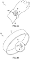
- FIGS 2A and 2B illustrate an example wearable device 200 for monitoring cardiovascular activity of a subject wearing the device 200.
- the wearable device 200 may be used as the first or second monitoring device 110, 120 described above with respect to the system 100 depicted in Figure 1 .
- the wearable device 200 is a wrist-mountable device (e.g., a wristwatch) that includes a mount 202 for mounting the device 200 to a wrist 204 of the subject.
- the mount 202 may take the form of a strap or band that can be wrapped around the wrist 204, or the mount 202 may include an adhesive substrate for adhering the wearable device 100 to the wrist 204 of the subject.
- the wearable device 200 may further include a housing 206 that includes a display 208 through which the subject may receive one or more indications or alerts.
- the display 208 may include a liquid crystal display (LCD) screen or the like configured to indicate, through textual or graphical information, a heart rate of the subject and/or a time of day.
- the housing 206 may include various other components for facilitating operation of the wearable device 200, such as a controller, data storage, and/or a communication interface for communicating with various other computing devices.
- a PPG sensor 210 may be disposed in an underside of the housing 206 so that the PPG sensor 210 faces the wrist 204 of the subject.
- the PPG sensor 210 includes a light source 212 and a light sensor 214.
- the light source 212 may be configured to emit illumination into a portion of subsurface vasculature of the subject, and the light sensor 214 may be configured to detect an intensity or other properties of light emitted from (e.g., reflected from, refracted by, scattered by) the portion of subsurface vasculature in response the illumination emitted from the light source 212.
- the device 200 may detect changes in blood volume in the subsurface vasculature as the subject's heart pumps blood. Because the detected changes in blood volume correspond to pulses of the subject's heart, the device 200 can use these detections to determine the subject's pulse rate.
- the light source 212 may include a light-emitting diode (LED), a laser, or some other light source configured to transmit illumination that can penetrate the wearer's skin into the portion of subsurface vasculature, for example, into a lumen of the subsurface vasculature.
- LED light-emitting diode
- laser laser
- some other light source configured to transmit illumination that can penetrate the wearer's skin into the portion of subsurface vasculature, for example, into a lumen of the subsurface vasculature.
- the transmitted illumination can be any kind of illumination that is benign to the wearer and that results at least in an amount of absorption by blood in the subsurface vasculature that is related to the volume of the blood in the subsurface vasculature, e.g., such that light responsively emitted from the body has one or more detectable properties related to the volume of flow and/or the pulse rate of blood in the portion of subsurface vasculature (e.g., an intensity related to the amount of blood in the portion of subsurface vasculature).
- the wavelength of the transmitted illumination could be specified to penetrate biological tissues of a wearer and could also be specified to be a wavelength that is absorbed and/or scattered by blood cells.
- the wavelength of the transmitted illumination could be a wavelength in the visible or near-infrared spectrum (e.g., between 400 nanometers and 1000 nanometers).
- the light sensor 214 may include one or more of a photodiode, a phototransistor, a photoresistor, an active pixel sensor, a CCD, a camera, a spectrometer, an interferometer, or some other light sensitive element configured to detect one or more properties of the emitted light.
- the components of the PPG sensor 210 may be miniaturized so that the wearable device 200 may be worn by the subject without significantly interfering with the subject's usual activities.
- the wearable device 200 may further include one or more motion sensors (not shown).
- the housing 206 may include one or more IMUs or accelerometers configured to adjust an output signal, such as a voltage or current, based on motion of the device 200.
- the motion sensors of the wearable device 200 may output a time-varying signal when undergoing movement, such as when the subject is swinging his or her arms while running. Other examples are possible as well.
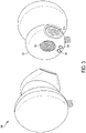
- FIG 3 illustrates another example wearable device 300 for monitoring cardiovascular activity of a subject wearing the device 300.
- the wearable device 300 may be used as the first or second monitoring device 110, 120 described above with respect to the system 100 depicted in Figure 1 .
- the wearable device 300 is an ear-mountable device (e.g., earbuds) that includes a housing 302 shaped so as to be insertable into a portion of the subject's ear.
- the housing 302 may include various components, such as a controller and data storage, for facilitating operation of the device 300.
- the wearable device 300 includes one or more speakers 304 disposed in the housing 302.
- the speakers 304 may be configured to output an audio signal, such as a music signal, that is provided to the wearable device 300 via a wired or wireless communication interface.
- the speakers 304 may be arranged in the housing 302 so that when the housing 302 is mounted to the subject's ear, the speakers 304 can output an audio signal that is directed into the subject's ear canal.
- the wearable device 300 may include a pulse detection system.
- the device 300 may include a light source 306 and a light sensor 308 arranged in the housing 302 of the device 300.
- the light source 306 and the light sensor 308 may be similar to those described above, and the wearable device 300 may similarly use the light source 306 and 308 to detect a pulse rate of the subject.
- the light source 306 would emit light toward a subsurface vasculature in the subject's ear, and the light sensor 308 would detect light reflected from and/or scattered by the subsurface vasculature.
- the wearable device 300 may further include one or more motion sensors, such as one or more IMUs or accelerometers arranged within the housing 302 of the device 300.
- the motion sensors may be configured to adjust an output signal, such as a voltage or current, based on motion of the device 300.
- the motion sensors of the wearable device 300 may output a time-varying signal when undergoing movement, such as when the subject's head is bouncing up and down while running. Other examples are possible as well.
- Figure 4A illustrates an example signal 400 output by a light sensor of a wrist-mountable device, such as the wearable device 200 depicted in Figure 2 .
- the light sensor may output a signal based on an intensity of light reflected from a subsurface vasculature of the subject.
- the signal 400 includes a number of peaks 402a-c that correspond with changes in reflected light caused by changes in blood volume in the subsurface vasculature and, thus, correspond with a heart rate of the subject.
- the signal 400 includes a number of other peaks 404a-d that do not correspond with the subject's heart rate, but are instead artifacts caused by motion. These artifacts may arise when the light sensor and/or the light source move relative to the subject. For instance, when the light sensor is moved farther away and/or angled away from the subject's subsurface vasculature, the light sensor may detect less light reflected from the vasculature, and/or the light sensor may detect light that is incident on the light sensor from alternative sources, such as ambient light.
- the amount of light incident on the subject's subsurface vasculature may be reduced, thereby reducing the amount of light detected by the light sensor.
- these motion artifacts 404a-d could arise, for example, when the subject is swinging his or her arms while running. Other examples are possible as well. If the wrist-mountable device is not secured tightly around the subject's wrist, then the device may be jostled, and the motion artifacts 404a-d may be seen on the output signal 400 of the light sensor.
- the wearable device may be configured to determine the subject's pulse rate based on a frequency of peaks in the light sensor output signal 400.
- the heart rate may be measured by counting the number of signal peaks within a time window or by determining a fundamental frequency or second harmonic of the signal, such as by using a fast Fourier transform (FFT) algorithm.
- FFT fast Fourier transform
- FIG. 4B illustrates an example frequency spectra plot 410 of the light sensor output 400, which may be obtained using an FFT algorithm. It should be understood that the frequency spectra plot 410 is for illustrative purposes only and may not be an exact representation of the spectral components of the light sensor output 400.
- the frequency spectra plot 410 includes a heart rate frequency peak 412 corresponding to a frequency of the heart rate peaks 402a-c, and the frequency spectra plot 410 includes a motion frequency peak 414 corresponding to a frequency of the motion artifacts 404a-d.
- the heart rate frequency peak 412 would be the dominant frequency peak, and the wearable device could use the frequency spectra plot 410 to determine the heart rate of the subject by merely identifying the dominant frequency in the frequency spectra plot 410.
- the motion artifacts 404a-d are similar in magnitude and/or larger in magnitude than the heart rate peaks 402a-c, it may be difficult for the wearable device to distinguish between the two. As such, the determined heart rate may be inaccurate.
- the wearable device may be configured to take into consideration a motion of the device when determining the subject's heart rate.
- the device may include one or more motion sensors, such as an IMU or an accelerometer, configured to adjust an output signal based on motion of the device.
- Figure 4C illustrates an example signal 420 output by a motion sensor of a wrist-mountable device, such as the wearable device 200 depicted in Figure 2 .
- the motion sensor output signal 420 may include a number of peaks 422a-d corresponding to motion of the wearable device. For instance, if the subject is wearing the device on his or her wrist while running, then the peaks 422a-d may correspond to each time the subject swings his or her arm. Other examples are possible as well. Because the motion artifacts 404a-d in the light sensor output signal 400 correspond to motion of the wearable device, the motion artifacts 404a-d should have a similar occurrence frequency as the peaks 422a-d in the output signal 420 of the motion sensor.
- Figure 4D illustrates an example frequency spectra plot 430 of the motion sensor output 420, which may be obtained using an FFT algorithm.
- the frequency spectra plot 430 is for illustrative purposes only and may not be an exact representation of the spectral components of the motion sensor output 420.
- the frequency spectra plot 430 includes a peak 432 corresponding to a dominant frequency of the motion sensor output 420, which corresponds to the frequency of the peaks 422a-d of the motion sensor output 420.
- frequency peak 432 of the motion sensor frequency spectra plot 430 aligns with frequency peak 414 of the light sensor frequency spectra plot 410.
- the frequency spectra 430 of the motion sensor output 420 may be used to filter the light sensor output signal 400 and/or the frequency spectra 410 of the light sensor output signal 400 in order to remove some or all of the motion artifacts 404a-d.
- the wearable device may identify one or more spectral components of the motion sensor output 420 (e.g., by using an FFT algorithm to identify one or more dominant frequencies of the motion sensor output 420), and the wearable device may then filter the light sensor output signal 400 and/or the frequency spectra signal 410 to remove the identified spectral components.
- the wearable device may identify 145 Hz as a dominant frequency of the motion sensor output signal 420 based on the frequency peak 432 occurring at 145 Hz.
- the wearable device could filter the light sensor output signal 400 to remove frequencies at or near 145 Hz.
- the wearable device could pass the light sensor output signal 400 through a band-pass, low-pass, or high-pass filter, which could be implemented in hardware and/or software.
- Figure 4E illustrates an example frequency spectra plot 440 of the light sensor output 400 after filtering the light sensor output 400 to remove the spectral components identified from the motion sensor output 420.
- the filtered frequency spectra plot 440 includes the frequency peak 412 corresponding to the frequency of the heart rate peaks 402a-c. Noticeably, the frequency peak 414 corresponding to the frequency of the motion artifacts 404a-d is no longer present. Thus, performing this filtering process can improve the quality of the light sensor output signal 400 by removing some of the motion artifacts, such as those corresponding to peaks 404a-d.
- the filtered frequency spectra plot 440 includes additional spectral components 442a-b that may be misinterpreted as a heart rate of the subject.
- the subject may be outfitted with multiple cardiovascular monitoring devices, and the multiple devices may work in tandem to determine the subject's heart rate.
- the multiple devices may work in tandem to determine the subject's heart rate.
- the subject in addition to wearing a wrist-mountable device, such as the wrist-mountable device 200 depicted in Figure 2 , the subject could also wear an ear-mountable device, such as the ear-mountable device 300 depicted in Figure 3 .
- the ear-mountable device may include a light source and a light sensor for detecting changes in blood volume in subsurface vasculature in the subject's ear, and the device may further include one or more motion sensors for detecting motion of the subject's head.
- Figures 5A-5E illustrate example signals obtained using light sensors and motion sensors, but in the context of an ear-mountable device rather than a wrist-mountable device.
- Figure 5A illustrates an example signal 500 output by a light sensor of the ear-mountable device
- Figure 5B illustrates an example frequency spectra plot 510 of the light sensor output 500
- Figure 5C illustrates an example signal 520 output by the motion sensor of the ear-mountable device
- Figure 5D illustrates an example frequency spectra plot 530 of the motion sensor output 520
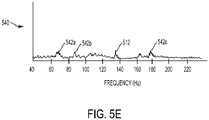
- Figure 5E illustrates an example frequency spectra plot 540 of the light sensor output 500 after filtering the light sensor output 500 to remove the spectral components identified from the motion sensor output 520.
- the ear-mountable device may be configured to process these example signals in a manner similar to that described above in the context of the wrist-mountable device.
- the light sensor output signal 500 of the ear-mountable device may include a number of peaks 502a-c that correspond with changes in reflected light caused by changes in blood volume in the subsurface vasculature and, thus, correspond with a heart rate of the subject; and the light sensor output signal 500 of the ear-mountable device may further include a number of motion artifact peaks 504a-d caused by motion of the subject's head.
- the frequency spectra plot 510 of the light sensor output 500 may include a heart rate frequency peak 512 corresponding to a frequency of the heart rate peaks 502a-c, and the frequency spectra plot 510 may include a motion frequency peak 514 corresponding to a frequency of the motion artifacts 504a-d.
- the ear-mountable device may take into consideration the output signal 520 of the motion sensor of the ear-mountable device.
- the motion sensor output signal 520 may include a number of peaks 522a-d corresponding to motion of the wearable device. For instance, if the subject is wearing the device in or on his or her ear while running, then the peaks 522a-d may correspond to each time the subject's head bobs up and down during a stride. Other examples are possible as well.
- the motion artifacts 504a-d in the light sensor output signal 500 correspond to motion of the wearable device
- the motion artifacts 504a-d should have a similar occurrence frequency as the peaks 522a-d in the output signal 520 of the motion sensor.
- the frequency spectra plot 530 of the motion sensor output 520 includes a peak 532 corresponding to a dominant frequency of the motion sensor output 520, which corresponds to the frequency of the peaks 522a-d of the motion sensor output 520.
- frequency peak 532 of the motion sensor frequency spectra plot 530 aligns with frequency peak 514 of the light sensor frequency spectra plot 510.
- the ear-mountable device may identify one or more spectral components of the motion sensor output 520 (e.g., by using an FFT algorithm to identify one or more dominant frequencies of the motion sensor output 520), and the device may then filter the light sensor output signal 500 and/or the frequency spectra signal 510 to remove the identified spectral components.
- This is shown in Figure 5E where the frequency peak 514 corresponding to the frequency of the motion artifacts 504a-d is no longer present, while the frequency peak 512 corresponding to the frequency of the heart rate peaks 502a-c is preserved. However, other artifacts may still remain, such as those having spectral components 542a-c.
- the filtered frequency spectra plot 440 of the wrist-mountable device can be compared with the filtered frequency spectra plot 540 of the ear-mountable device. Because the wrist-mountable device and the ear-mountable device are mounted to different body parts, the devices may undergo different types of motion. Accordingly, the artifacts that appear in the output signals of their respective light sensors may have different spectral components. For instance, spectral components 442a-b of artifacts detected by the wrist-mountable device have a different frequency than spectral components 542a-c of artifacts detected by the ear-mountable device.
- each filtered frequency spectra plot should include a spectral component at the frequency of the subject's heart rate.
- both the filtered frequency spectra plot 440 of the wrist-mountable device and the filtered frequency spectra plot 540 of the ear-mountable device include a spectral component having a frequency of approximately 135 Hz (i.e., spectral components 412 and 512).
- either or both of the wearable devices may determine that the subject's heart rate is 135 Hz based on the filtered frequency spectra plots each having a spectral component at that frequency.
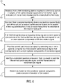
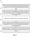
- Figure 6 is a flow chart of an example method 600 that can be carried out in accordance with the present disclosure to determine one or more cardiovascular characteristics of a subject.
- the method 600 includes receiving, from a first monitoring device coupled to a first body part of a subject, a first cardiovascular signal and a first motion signal indicative of one or more measurements obtained at the first body part.
- the first monitoring device may be a wrist-mountable device mounted to the subject's wrist, and the wrist-mountable device may generate the first cardiovascular signal and the first motion signal from measurements taken at the subject's wrist.
- the first cardiovascular signal may be a PPG signal generated by using a light source and a light sensor, and the first motion signal may be generated using an IMU or an accelerometer.
- the method 600 includes receiving, from a second monitoring device coupled to a second body part of the subject, a second cardiovascular signal and a second motion signal indicative of one or more measurements obtained at the second body part.
- the second monitoring device may be an ear-mountable device mounted to the subject's ear, and the ear-mountable device may generate the second cardiovascular signal and the second motion signal from measurements taken at the subject's ear.
- the second cardiovascular signal may be a PPG signal generated by using a light source and a light sensor, and the second motion signal may be generated using an IMU or an accelerometer.
- the method 600 includes filtering the first cardiovascular signal by removing one or more spectral components of the first cardiovascular signal that correspond to one or more spectral components of the first motion signal.
- this may involve transforming the first motion signal using an FFT algorithm to identify the one or more spectral components of the first motion signal.
- the identified spectral components could include any spectral component of the transformed first motion signal having a threshold high magnitude relative to other spectral components.
- the method 600 includes filtering the second cardiovascular signal by removing one or more spectral components of the second cardiovascular signal that correspond to one or more spectral components of the second motion signal.
- this may involve transforming the second motion signal using an FFT algorithm to identify the one or more spectral components of the second motion signal.
- the identified spectral components could include any spectral component of the transformed second motion signal having a threshold high magnitude relative to other spectral components.
- the method 600 includes identifying a correlated spectral component that is present in both the filtered first cardiovascular signal and the filtered second cardiovascular signal. And at block 612, the method 600 includes determining, based on the correlated spectral component, cardiovascular information of the subject.
- the filtered first cardiovascular signal and the filtered second cardiovascular signal may include various other spectral components associated with artifacts in the first and second cardiovascular signals that were not filtered out at blocks 606 and 608, the filtered first cardiovascular signal and the filtered second cardiovascular signal both include a correlated spectral component that corresponds to a heart rate of the subject. Accordingly, by identifying the correlated spectral component that is present in both the first and second filtered cardiovascular signals, the subject's heart rate may be determined.
- the method 600 could include additional or alternative steps.
- the method 600 could include providing, to a user, an indication of the determined cardiovascular information.
- the method 600 could include displaying a graphical or textual representation of the cardiovascular information.
- the method 600 could include generating and outputting an audio or visual alert based on the cardiovascular information, such as in response to determining that the subject's heart rate is above a threshold high value and/or below a threshold low value.
- the method 600 could include transmitting indications of the determined cardiovascular information to a remote system (e.g., a server or a cloud computing service) and receiving, from the remote system, a health state or other information about the user determined, based on the cardiovascular information, by the remote system.
- a remote system e.g., a server or a cloud computing service
- the cardiovascular signals from the devices may be combined, and the combined signal may be filtered to remove spectral components identified based on motion sensors located on each device.
- Figure 7 is a flow chart of such an example method 700 that can be carried out in accordance with the present disclosure to determine one or more cardiovascular characteristics of a subject.
- the method 700 includes receiving, from a first monitoring device coupled to a first body part of a subject, a first cardiovascular signal and a first motion signal indicative of one or more measurements obtained at the first body part.
- the first monitoring device may be a wrist-mountable device mounted to the subject's wrist, and the wrist-mountable device may generate the first cardiovascular signal and the first motion signal from measurements taken at the subject's wrist.
- the first cardiovascular signal may be a PPG signal generated by using a light source and a light sensor, and the first motion signal may be generated using an IMU or an accelerometer.
- the method 700 includes receiving, from a second monitoring device coupled to a second body part of the subject, a second cardiovascular signal and a second motion signal indicative of one or more measurements obtained at the second body part.
- the second monitoring device may be an ear-mountable device mounted to the subject's ear, and the ear-mountable device may generate the second cardiovascular signal and the second motion signal from measurements taken at the subject's ear.
- the second cardiovascular signal may be a PPG signal generated by using a light source and a light sensor, and the second motion signal may be generated using an IMU or an accelerometer.
- the method 700 includes combining the received first and second cardiovascular signals, such as by feeding the first and second cardiovascular signals into a summing amplifier or the like.
- the method 700 includes filtering the combined cardiovascular signals by removing one or more spectral components of the combined cardiovascular signals that correspond to one or more spectral components of the first and second motion signals.
- this may involve transforming the first motion signal and the second motion signal using an FFT algorithm to identify the one or more spectral components of the first and second motion signals.
- the identified spectral components could include any spectral component of the transformed first and second motion signals having a threshold high magnitude relative to other spectral components.
- certain artifacts that appear in the combined cardiovascular signals due to motion of the subject's wrist, motion of the subject's head, or due to other sources unrelated to the subject's heart rate may be removed from the combined cardiovascular signals.
- the method 700 includes determining, based on a remaining spectral component of the filtered combined cardiovascular signals, cardiovascular information of the subject. This may involve identifying the strongest remaining spectral component of the filtered combined cardiovascular signals. Because the spectral components from both the first and second motion signals have been removed from the combined cardiovascular signals, the strongest remaining spectral component likely corresponds to the subject's heart pumping. Accordingly, the determined cardiovascular information may include the subject's heart rate, and the determined heart rate may be equivalent to the frequency of the remaining spectral component of the filtered combined cardiovascular signals.
- the method 700 could include additional or alternative steps.
- the method 700 could include providing, to a user, an indication of the determined cardiovascular information.
- the method 700 could include displaying a graphical or textual representation of the cardiovascular information.
- the method 700 could include generating and outputting an audio or visual alert based on the cardiovascular information, such as in response to determining that the subject's heart rate is above a threshold high value and/or below a threshold low value.
- the method 700 could include transmitting indications of the determined cardiovascular information to a remote system (e.g., a server or a cloud computing service) and receiving, from the remote system, a health state or other information about the user determined, based on the cardiovascular information, by the remote system
- a remote system e.g., a server or a cloud computing service
- the wrist-mountable device may include a controller for obtaining the first cardiovascular signal and the first motion signal and for filtering the first cardiovascular signal to remove one or more spectral components of the first motion signal.
- the ear-mountable device may include a controller for obtaining the second cardiovascular signal and the second motion signal and for filtering the second cardiovascular signal to remove one or more spectral components of the second motion signal. The wrist-mountable device and the ear-mountable device may subsequently engage in wired or wireless communication for exchanging information associated with the filtered signals and identifying the correlated spectral component.
- the ear-mountable device may transmit information indicative of the filtered first cardiovascular signal to the wrist-mountable device, and the wrist-mountable device may use the transmitted information to identify the correlated spectral component.
- data may be transmitted to a single device, and the operations described herein may be performed by that single device.
- the ear-mountable device may transmit the first cardiovascular signal and/or the first motion signal (or information indicative thereof) to the wrist-mountable device.
- the controller of the wrist-mountable device may subsequently perform some or all of the operations described herein. Other examples are possible as well.
- the specific embodiments disclosed herein are related to a wrist-mountable device and an ear-mountable device
- various other wearable devices may alternatively or additionally be used in accordance with the methods described herein.
- the wrist-mountable device and/or the ear-mountable device could be replaced by any device that is capable of being worn at, on or in proximity to a body surface, such as an ankle, waist, chest, or other body part.
- a third wearable device could provide a third cardiovascular signal and a third motion signal; the third cardiovascular signal could be filtered to remove one or more spectral components of the third motion signal; and cardiovascular information of the subject could be determined based on a correlated spectral component that is present in the filtered first, second, and third cardiovascular signals.
- Such privacy controls include, at least, anonymization of device identifiers, transparency and user controls, including functionality that would enable users to modify or delete information relating to the user's use of a product.
- the users may be provided with an opportunity to control whether programs or features collect user information (e.g., information about a user's medical history, social network, social actions or activities, profession, a user's preferences, or a user's current location), or to control whether and/or how to receive content from the content server that may be more relevant to the user.
- user information e.g., information about a user's medical history, social network, social actions or activities, profession, a user's preferences, or a user's current location
- certain data may be treated in one or more ways before it is stored or used, so that personally identifiable information is removed.
- a user's identity may be treated so that no personally identifiable information can be determined for the user, or a user's geographic location may be generalized where location information is obtained (such as to a city, ZIP code, or state level), so that a particular location of a user cannot be determined.
- location information such as to a city, ZIP code, or state level
- the user may have control over how information is collected about the user and used by a content server.
Landscapes
- Health & Medical Sciences (AREA)
- Life Sciences & Earth Sciences (AREA)
- Engineering & Computer Science (AREA)
- Cardiology (AREA)
- Biomedical Technology (AREA)
- Public Health (AREA)
- Physics & Mathematics (AREA)
- Heart & Thoracic Surgery (AREA)
- Medical Informatics (AREA)
- Molecular Biology (AREA)
- Surgery (AREA)
- Animal Behavior & Ethology (AREA)
- General Health & Medical Sciences (AREA)
- Pathology (AREA)
- Veterinary Medicine (AREA)
- Biophysics (AREA)
- Physiology (AREA)
- Signal Processing (AREA)
- Artificial Intelligence (AREA)
- Computer Vision & Pattern Recognition (AREA)
- Psychiatry (AREA)
- Dentistry (AREA)
- Oral & Maxillofacial Surgery (AREA)
- Measuring Pulse, Heart Rate, Blood Pressure Or Blood Flow (AREA)
Claims (15)
- System, umfassend:eine erste Überwachungsvorrichtung (110), die konfiguriert ist, an einen ersten Körperteil einer Zielperson zu koppeln, wobei die erste Überwachungsvorrichtung (110) konfiguriert ist, ein erstes kardiovaskuläres Signal und ein erstes Bewegungssignal an dem ersten Körperteil zu messen;eine zweite Überwachungsvorrichtung (120), die konfiguriert ist, an einen zweiten Körperteil der Zielperson zu koppeln, wobei die zweite Überwachungsvorrichtung (120) konfiguriert ist, ein zweites kardiovaskuläres Signal und ein zweites Bewegungssignal an dem zweiten Körperteil zu messen; undeine Steuerung (130), die konfiguriert ist zum:Empfangen des ersten und des zweiten kardiovaskulären Signals und des ersten und des zweiten Bewegungssignals von der ersten und der zweiten Überwachungsvorrichtung (120);Filtern des ersten kardiovaskulären Signals durch Entfernen einer oder mehrerer Spektralkomponenten des ersten kardiovaskulären Signals, die einer oder mehreren Spektralkomponenten des ersten Bewegungssignals entsprechen;Filtern des zweiten kardiovaskulären Signals durch Entfernen einer oder mehrerer Spektralkomponenten des zweiten kardiovaskulären Signals, die einer oder mehreren Spektralkomponenten des zweiten Bewegungssignals entsprechen;Identifizieren einer korrelierten Spektralkomponente, die sowohl in dem gefilterten ersten kardiovaskulären Signal als auch dem gefilterten zweiten kardiovaskulären Signal vorhanden ist; undErmitteln, basierend auf der korrelierten Spektralkomponente, kardiovaskulärer Informationen der Zielperson.
- System nach Anspruch 1, wobei das erste kardiovaskuläre Signal Folgendes umfasst: (i) eine erste Pulsratenkomponente, die auf eine Blutpulsrate in dem ersten Körperteil zurückzuführen ist, und (ii) eine erste Artefaktkomponente, die nicht auf die Blutpulsrate in dem ersten Körperteil zurückzuführen ist, und wobei das Entfernen einer oder mehrerer Spektralkomponenten des ersten kardiovaskulären Signals, die einer oder mehreren Spektralkomponenten des ersten Bewegungssignals entsprechen, ein Entfernen der ersten Artefaktkomponente aus dem ersten kardiovaskulären Signal umfasst; und
wobei das zweite kardiovaskuläre Signal Folgendes umfasst: (i) eine zweite Pulsratenkomponente, die auf eine Blutpulsrate in dem zweiten Körperteil zurückzuführen ist, und (ii) eine zweite Artefaktkomponente, die nicht auf die Blutpulsrate in dem zweiten Körperteil zurückzuführen ist, und wobei das Entfernen einer oder mehrerer Spektralkomponenten des zweiten kardiovaskulären Signals, die einer oder mehreren Spektralkomponenten des zweiten Bewegungssignals entsprechen, ein Entfernen der zweiten Artefaktkomponente aus dem zweiten kardiovaskulären Signal umfasst. - System nach Anspruch 1, wobei das Ermitteln der kardiovaskulären Informationen der Zielperson ein Ermitteln einer Herzfrequenz der Zielperson basierend auf einer Frequenz der korrelierten Spektralkomponente umfasst.
- System nach Anspruch 1, wobei die erste Überwachungsvorrichtung (110) Folgendes umfasst: (i) einen ersten photoplethysmographischen (PPG) Sensor, der konfiguriert ist, das erste kardiovaskuläre Signal zu messen, und (ii) einen ersten Beschleunigungssensor, der konfiguriert ist, das erste Bewegungssignal zu messen; und
wobei die zweite Überwachungsvorrichtung (120) Folgendes umfasst: (i) einen zweiten PPG-Sensor, der konfiguriert ist, das zweite kardiovaskuläre Signal zu messen, und (ii) einen zweiten Beschleunigungssensor, der konfiguriert ist, das zweite Bewegungssignal zu messen. - System nach Anspruch 1, wobei der erste Körperteil der Zielperson ein Ohr der Zielperson ist, und wobei die erste Überwachungsvorrichtung (110) einen Ohrhörer umfasst, der konfiguriert ist, an oder in dem Ohr der Zielperson getragen zu werden, wobei der Ohrhörer insbesondere einen PPG-Sensor umfasst, der konfiguriert ist, eine Blutpulsrate im Ohr der Zielperson zu messen.
- System nach Anspruch 1, wobei der zweite Körperteil der Zielperson ein Handgelenk der Zielperson ist, und wobei die zweite Überwachungsvorrichtung (120) ein Armband umfasst, das konfiguriert ist, um das Handgelenk der Zielperson getragen zu werden, wobei das Armband insbesondere einen PPG-Sensor umfasst, der konfiguriert ist, eine Blutpulsrate im Handgelenk der Zielperson zu messen.
- Verfahren, umfassend:Empfangen, von einer ersten Überwachungsvorrichtung (110), die an einen ersten Körperteil einer Zielperson gekoppelt ist, eines ersten kardiovaskulären Signals und eines ersten Bewegungssignals, die einen oder mehrere Messwerte angeben, die an dem ersten Körperteil erhalten werden;Empfangen, von einer zweiten Überwachungsvorrichtung (120), die an einen zweiten Körperteil der Zielperson gekoppelt ist, eines zweiten kardiovaskulären Signals und eines zweiten Bewegungssignals, die einen oder mehrere Messwerte angeben, die an dem zweiten Körperteil erhalten werden;Filtern des ersten kardiovaskulären Signals durch Entfernen einer oder mehrerer Spektralkomponenten des ersten kardiovaskulären Signals, die einer oder mehreren Spektralkomponenten des ersten Bewegungssignals entsprechen;Filtern des zweiten kardiovaskulären Signals durch Entfernen einer oder mehrerer Spektralkomponenten des zweiten kardiovaskulären Signals, die einer oder mehreren Spektralkomponenten des zweiten Bewegungssignals entsprechen;Identifizieren einer korrelierten Spektralkomponente, die sowohl in dem gefilterten ersten kardiovaskulären Signal als auch dem gefilterten zweiten kardiovaskulären Signal vorhanden ist; undErmitteln, basierend auf der korrelierten Spektralkomponente, kardiovaskulärer Informationen der Zielperson.
- Verfahren nach Anspruch 7, ferner umfassend:Messen, unter Nutzung der ersten Überwachungsvorrichtung (110), des ersten kardiovaskulären Signals und des ersten Bewegungssignals an dem ersten Körperteil; undMessen, unter Nutzung der zweiten Überwachungsvorrichtung (120), des zweiten kardiovaskulären Signals und des zweiten Bewegungssignals an dem zweiten Körperteil, wobei das Messen des ersten kardiovaskulären Signals insbesondere ein Verwenden eines ersten photoplethysmographischen (PPG) Sensors der ersten Überwachungsvorrichtung (110) zum Messen des ersten kardiovaskulären Signals umfasst, wobei das Messen des ersten Bewegungssignals ein Verwenden eines ersten Beschleunigungssensors der ersten Überwachungsvorrichtung (110) zum Messen des ersten Bewegungssignals umfasst, wobei das Messen des zweiten kardiovaskulären Signals ein Verwenden eines zweiten PPG-Sensors der zweiten Überwachungsvorrichtung (120) zum Messen des zweiten kardiovaskulären Signals umfasst, und wobei das Messen des zweiten Bewegungssignals ein Verwenden eines zweiten Beschleunigungssensors der zweiten Überwachungsvorrichtung (120) zum Messen des zweiten Bewegungssignals umfasst.
- Verfahren nach Anspruch 7, wobei das erste kardiovaskuläre Signal Folgendes umfasst: (i) eine erste Pulsratenkomponente, die auf eine Blutpulsrate in dem ersten Körperteil zurückzuführen ist, und (ii) eine erste Artefaktkomponente, die nicht auf die Blutpulsrate in dem ersten Körperteil zurückzuführen ist, und wobei das Entfernen einer oder mehrerer Spektralkomponenten des ersten kardiovaskulären Signals, die einer oder mehreren Spektralkomponenten des ersten Bewegungssignals entsprechen, ein Entfernen der ersten Artefaktkomponente aus dem ersten kardiovaskulären Signal umfasst; und
wobei das zweite kardiovaskuläre Signal Folgendes umfasst: (i) eine zweite Pulsratenkomponente, die auf eine Blutpulsrate in dem zweiten Körperteil zurückzuführen ist, und (ii) eine zweite Artefaktkomponente, die nicht auf die Blutpulsrate in dem zweiten Körperteil zurückzuführen ist, und wobei das Entfernen einer oder mehrerer Spektralkomponenten des zweiten kardiovaskulären Signals, die einer oder mehreren Spektralkomponenten des zweiten Bewegungssignals entsprechen, ein Entfernen der zweiten Artefaktkomponente aus dem zweiten kardiovaskulären Signal umfasst. - Verfahren nach Anspruch 7, wobei das Ermitteln der kardiovaskulären Informationen der Zielperson ein Ermitteln einer Herzfrequenz der Zielperson basierend auf einer Frequenz der korrelierten Spektralkomponente umfasst.
- Verfahren nach Anspruch 7, wobei der erste Körperteil der Zielperson ein Ohr der Zielperson ist, und wobei die erste Überwachungsvorrichtung (110) einen Ohrhörer umfasst, der an oder in dem Ohr der Zielperson getragen wird, oder wobei der zweite Körperteil der Zielperson ein Handgelenk der Zielperson ist, und wobei die zweite Überwachungsvorrichtung (120) ein Armband umfasst, das um das Handgelenk der Zielperson getragen wird.
- System, umfassend:eine erste Überwachungsvorrichtung (110), die konfiguriert ist, an einen ersten Körperteil einer Zielperson zu koppeln, wobei die erste Überwachungsvorrichtung (110) konfiguriert ist, ein erstes kardiovaskuläres Signal und ein erstes Bewegungssignal an dem ersten Körperteil zu messen;eine zweite Überwachungsvorrichtung (120), die konfiguriert ist, an einen zweiten Körperteil der Zielperson zu koppeln, wobei die zweite Überwachungsvorrichtung (120) konfiguriert ist, ein zweites kardiovaskuläres Signal und ein zweites Bewegungssignal an dem zweiten Körperteil zu messen; undeine Steuerung (130), die konfiguriert ist zum:Empfangen des ersten und des zweiten kardiovaskulären Signals und des ersten und des zweiten Bewegungssignals von der ersten und der zweiten Überwachungsvorrichtung (120);Kombinieren des empfangenen ersten und zweiten kardiovaskulären Signals;Filtern des kombinierten kardiovaskulären Signals durch Entfernen einer oder mehrerer Spektralkomponenten des kombinierten kardiovaskulären Signals, die einer oder mehreren Spektralkomponenten des ersten und des zweiten Bewegungssignals entsprechen; undErmitteln, basierend auf einer verbleibenden Spektralkomponente der gefilterten kombinierten kardiovaskulären Signale, von kardiovaskulären Informationen der Zielperson.
- System nach Anspruch 12, wobei das erste kardiovaskuläre Signal Folgendes umfasst: (i) eine erste Pulsratenkomponente, die auf eine Blutpulsrate in dem ersten Körperteil zurückzuführen ist, und (ii) eine erste Artefaktkomponente, die nicht auf die Blutpulsrate in dem ersten Körperteil zurückzuführen ist, wobei das zweite kardiovaskuläre Signal Folgendes umfasst: (i) eine zweite Pulsratenkomponente, die auf eine Blutpulsrate in dem zweiten Körperteil zurückzuführen ist, und (ii) eine zweite Artefaktkomponente, die nicht auf die Blutpulsrate in dem zweiten Körperteil zurückzuführen ist, und wobei das Entfernen einer oder mehrerer Spektralkomponenten der kombinierten kardiovaskulären Signale, die einer oder mehreren Spektralkomponenten des ersten und des zweiten Bewegungssignals entsprechen, ein Entfernen der ersten und der zweiten Artefaktkomponente aus den kombinierten kardiovaskulären Signalen umfasst.
- System nach Anspruch 12, wobei das Ermitteln der kardiovaskulären Informationen der Zielperson ein Ermitteln einer Herzfrequenz der Zielperson basierend auf einer Frequenz der verbleibenden Spektralkomponenten der gefilterten kombinierten kardiovaskulären Signale umfasst.
- System nach Anspruch 12, wobei die erste Überwachungsvorrichtung (110) Folgendes umfasst: (i) einen ersten photoplethysmographischen (PPG) Sensor, der konfiguriert ist, das erste kardiovaskuläre Signal zu messen, und (ii) einen ersten Beschleunigungssensor, der konfiguriert ist, das erste Bewegungssignal zu messen; und
wobei die zweite Überwachungsvorrichtung (120) Folgendes umfasst: (i) einen zweiten PPG-Sensor, der konfiguriert ist, das zweite kardiovaskuläre Signal zu messen, und (ii) einen zweiten Beschleunigungssensor, der konfiguriert ist, das zweite Bewegungssignal zu messen, oder wobei der erste Körperteil der Zielperson ein Ohr der Zielperson ist, wobei die erste Überwachungsvorrichtung (110) einen Ohrhörer umfasst, der konfiguriert ist, an oder in dem Ohr der Zielperson getragen zu werden, wobei der zweite Körperteil der Zielperson ein Handgelenk der Zielperson ist, und wobei die zweite Überwachungsvorrichtung (120) ein Armband umfasst, das konfiguriert ist, um das Handgelenk der Zielperson getragen zu werden.
Applications Claiming Priority (2)
| Application Number | Priority Date | Filing Date | Title |
|---|---|---|---|
| US15/825,234 US12016666B2 (en) | 2017-11-29 | 2017-11-29 | Cardiovascular monitoring using multiple sensors |
| PCT/US2018/061760 WO2019108428A1 (en) | 2017-11-29 | 2018-11-19 | Cardiovascular monitoring using multiple sensors |
Publications (2)
| Publication Number | Publication Date |
|---|---|
| EP3716841A1 EP3716841A1 (de) | 2020-10-07 |
| EP3716841B1 true EP3716841B1 (de) | 2022-09-21 |
Family
ID=64870557
Family Applications (1)
| Application Number | Title | Priority Date | Filing Date |
|---|---|---|---|
| EP18826133.3A Active EP3716841B1 (de) | 2017-11-29 | 2018-11-19 | Kardiovaskuläre überwachung mit mehreren sensoren |
Country Status (4)
| Country | Link |
|---|---|
| US (2) | US12016666B2 (de) |
| EP (1) | EP3716841B1 (de) |
| CN (2) | CN111417338B (de) |
| WO (1) | WO2019108428A1 (de) |
Families Citing this family (5)
| Publication number | Priority date | Publication date | Assignee | Title |
|---|---|---|---|---|
| CN111920395B (zh) * | 2020-07-22 | 2024-04-09 | 上海掌门科技有限公司 | 一种脉搏采集装置 |
| US20230329569A1 (en) * | 2020-09-09 | 2023-10-19 | Google Llc | System And Method For Multi-Node PPG On Wearable Devices |
| US20230240609A1 (en) * | 2022-02-02 | 2023-08-03 | Meta Platforms Technologies, Llc | In-ear optical sensors for ar/vr applications and devices |
| JP2024141375A (ja) * | 2023-03-29 | 2024-10-10 | セイコーエプソン株式会社 | 生体情報測定装置、及び生体情報測定セット |
| KR20240160708A (ko) | 2023-05-02 | 2024-11-12 | 삼성디스플레이 주식회사 | 표시 장치 |
Family Cites Families (26)
| Publication number | Priority date | Publication date | Assignee | Title |
|---|---|---|---|---|
| US7991448B2 (en) | 1998-10-15 | 2011-08-02 | Philips Electronics North America Corporation | Method, apparatus, and system for removing motion artifacts from measurements of bodily parameters |
| US6616613B1 (en) * | 2000-04-27 | 2003-09-09 | Vitalsines International, Inc. | Physiological signal monitoring system |
| EP1485009A1 (de) | 2002-02-22 | 2004-12-15 | Datex-Ohmeda, Inc. | Überwachung von physiologischen parametern auf grundlage von schwankungen in einem photoplethysmographischen signal |
| EP2162059B1 (de) * | 2007-06-12 | 2021-01-13 | Sotera Wireless, Inc. | Vitalzeichenmonitor und verfahren zur messung des blutdrucks mit optischen, elektrischen und druck-wellenformen |
| US20090054752A1 (en) * | 2007-08-22 | 2009-02-26 | Motorola, Inc. | Method and apparatus for photoplethysmographic sensing |
| WO2009043028A2 (en) * | 2007-09-28 | 2009-04-02 | Tiax Llc | Measurement of physiological signals |
| US9833171B2 (en) | 2010-08-04 | 2017-12-05 | Koninklijke Philips N.V. | Monitoring of vital body signals during movement |
| WO2012021765A2 (en) | 2010-08-12 | 2012-02-16 | Board Of Trustees Of Michigan State University | Methods and apparatus for determining arterial pulse wave velocity |
| CN103596492B (zh) * | 2011-02-09 | 2017-02-22 | 麻省理工学院 | 耳戴式生命体征监视器 |
| US9522317B2 (en) * | 2011-08-19 | 2016-12-20 | Pulson, Inc. | Systems and methods for coordinating musculoskeletal and cardiovascular or cerebrovascular hemodynamics |
| US8948832B2 (en) * | 2012-06-22 | 2015-02-03 | Fitbit, Inc. | Wearable heart rate monitor |
| US20150100141A1 (en) * | 2013-10-07 | 2015-04-09 | Zinc Software Limited | Head Worn Sensor Device and System for Exercise Tracking and Scoring |
| US20150313484A1 (en) * | 2014-01-06 | 2015-11-05 | Scanadu Incorporated | Portable device with multiple integrated sensors for vital signs scanning |
| RU2016151983A (ru) | 2014-05-28 | 2018-07-02 | Конинклейке Филипс Н.В. | Уменьшение артефактов движения с помощью многоканальных сигналов ФПГ |
| US10201286B2 (en) | 2014-08-22 | 2019-02-12 | Apple Inc. | Frequency domain projection algorithm |
| US20160051158A1 (en) * | 2014-08-22 | 2016-02-25 | Apple Inc. | Harmonic template classifier |
| US9794653B2 (en) | 2014-09-27 | 2017-10-17 | Valencell, Inc. | Methods and apparatus for improving signal quality in wearable biometric monitoring devices |
| US10064582B2 (en) | 2015-01-19 | 2018-09-04 | Google Llc | Noninvasive determination of cardiac health and other functional states and trends for human physiological systems |
| US9629574B2 (en) | 2015-04-29 | 2017-04-25 | Salutron Inc. | Multi-position, multi-parameter user-wearable sensor systems and methods for use therewith |
| US9814400B1 (en) | 2015-05-26 | 2017-11-14 | Verily Life Sciences Llc | Method for improving accuracy of pulse rate estimation |
| US10595785B2 (en) | 2015-10-01 | 2020-03-24 | Silicon Laboratories Inc. | Plethysmography heart rate monitor noise reduction using differential sensors |
| US10722177B2 (en) | 2015-12-18 | 2020-07-28 | Verily Life Sciences Llc | Cardiovascular monitoring using combined measurements |
| EP3416538A1 (de) | 2016-02-15 | 2018-12-26 | Koninklijke Philips N.V. | Vorrichtung und verfahren zum extrahieren von herzfrequenzinformationen |
| CN109195510A (zh) | 2016-04-29 | 2019-01-11 | 飞比特公司 | 多信道光电容积脉搏波传感器 |
| GB2551201A (en) * | 2016-06-10 | 2017-12-13 | Polar Electro Oy | Multi-sensor system for estimating blood pulse wave characteristics |
| GB2547736B (en) * | 2016-07-01 | 2018-06-20 | Polar Electro Oy | Photoplethysmographic sensor configuration |
-
2017
- 2017-11-29 US US15/825,234 patent/US12016666B2/en active Active
-
2018
- 2018-11-19 CN CN201880077465.3A patent/CN111417338B/zh active Active
- 2018-11-19 WO PCT/US2018/061760 patent/WO2019108428A1/en not_active Ceased
- 2018-11-19 EP EP18826133.3A patent/EP3716841B1/de active Active
- 2018-11-19 CN CN202311794357.7A patent/CN117796780A/zh active Pending
-
2024
- 2024-05-07 US US18/657,361 patent/US20240285183A1/en active Pending
Also Published As
| Publication number | Publication date |
|---|---|
| CN117796780A (zh) | 2024-04-02 |
| EP3716841A1 (de) | 2020-10-07 |
| US20190159690A1 (en) | 2019-05-30 |
| WO2019108428A1 (en) | 2019-06-06 |
| CN111417338B (zh) | 2023-12-12 |
| CN111417338A (zh) | 2020-07-14 |
| US20240285183A1 (en) | 2024-08-29 |
| US12016666B2 (en) | 2024-06-25 |
Similar Documents
| Publication | Publication Date | Title |
|---|---|---|
| US20240285183A1 (en) | Cardiovascular Monitoring Using Multiple Sensors | |
| US20220409069A1 (en) | Methods and systems for detecting physiology for monitoring cardiac health | |
| US10390730B1 (en) | Methods, systems, and devices for determining a respiration rate | |
| US10251571B1 (en) | Method for improving accuracy of pulse rate estimation | |
| RU2640006C2 (ru) | Способ и система идентификации артефактов перемещения и повышения надежности измерений и сигналов тревоги в фотоплетизмографических измерениях | |
| US9826940B1 (en) | Optical tracking of heart rate using PLL optimization | |
| US10335087B2 (en) | Biosignal processing apparatus and biosignal processing method | |
| US10966642B2 (en) | Photoplethysmography apparatus | |
| US20150305674A1 (en) | Systems and Methods for Measuring Hydration in a Human Subject | |
| US11147505B1 (en) | Methods, systems and devices for identifying an abnormal sleep condition | |
| US20170181680A1 (en) | Oxygen saturation measuring apparatus and oxygen saturation measuring method thereof | |
| EP3915476A1 (de) | Blutsauerstoffdetektionsverfahren und -vorrichtung | |
| US20180303358A1 (en) | Vital signs sensor and method of measuring vital signs of a user | |
| WO2017089479A1 (en) | Non-invasive human condition monitoring device | |
| EP3106086B1 (de) | Photoelektrisches impulssignalmessverfahren und messvorrichtung | |
| US20160361023A1 (en) | Techniques for determining physiological properties of a user using vascular-related signals qualified by activity state | |
| WO2016003593A1 (en) | Methods for reducing noise in optical biological sensors | |
| WO2020160058A1 (en) | Systems and methods for computationally efficient non-invasive blood quality measurement | |
| EP3737286A1 (de) | System und verfahren zur nichtinvasiven überwachung der hämatokritkonzentraton | |
| CN112203576A (zh) | 用于非侵入式地监测晚期糖基化终末产物(age)的系统和方法 | |
| KR20230146347A (ko) | 체수분 상태 추정 장치 및 방법 | |
| Mouradian et al. | Continuous wearable health monitoring using novel PPG optical sensor and device | |
| US20190274547A1 (en) | System and method of noncontact vital signs monitoring through light sensing | |
| KR20110094405A (ko) | 무채혈 혈당측정방법 및 상기 무채혈 혈당측정방법을 이용한 무채혈 혈당측정장치 | |
| WO2024097361A1 (en) | Wearable vital signs monitor with skin tone detection |
Legal Events
| Date | Code | Title | Description |
|---|---|---|---|
| STAA | Information on the status of an ep patent application or granted ep patent |
Free format text: STATUS: UNKNOWN |
|
| STAA | Information on the status of an ep patent application or granted ep patent |
Free format text: STATUS: THE INTERNATIONAL PUBLICATION HAS BEEN MADE |
|
| PUAI | Public reference made under article 153(3) epc to a published international application that has entered the european phase |
Free format text: ORIGINAL CODE: 0009012 |
|
| STAA | Information on the status of an ep patent application or granted ep patent |
Free format text: STATUS: REQUEST FOR EXAMINATION WAS MADE |
|
| 17P | Request for examination filed |
Effective date: 20200525 |
|
| AK | Designated contracting states |
Kind code of ref document: A1 Designated state(s): AL AT BE BG CH CY CZ DE DK EE ES FI FR GB GR HR HU IE IS IT LI LT LU LV MC MK MT NL NO PL PT RO RS SE SI SK SM TR |
|
| AX | Request for extension of the european patent |
Extension state: BA ME |
|
| DAV | Request for validation of the european patent (deleted) | ||
| DAX | Request for extension of the european patent (deleted) | ||
| GRAP | Despatch of communication of intention to grant a patent |
Free format text: ORIGINAL CODE: EPIDOSNIGR1 |
|
| STAA | Information on the status of an ep patent application or granted ep patent |
Free format text: STATUS: GRANT OF PATENT IS INTENDED |
|
| INTG | Intention to grant announced |
Effective date: 20220412 |
|
| GRAS | Grant fee paid |
Free format text: ORIGINAL CODE: EPIDOSNIGR3 |
|
| GRAA | (expected) grant |
Free format text: ORIGINAL CODE: 0009210 |
|
| STAA | Information on the status of an ep patent application or granted ep patent |
Free format text: STATUS: THE PATENT HAS BEEN GRANTED |
|
| AK | Designated contracting states |
Kind code of ref document: B1 Designated state(s): AL AT BE BG CH CY CZ DE DK EE ES FI FR GB GR HR HU IE IS IT LI LT LU LV MC MK MT NL NO PL PT RO RS SE SI SK SM TR |
|
| REG | Reference to a national code |
Ref country code: GB Ref legal event code: FG4D |
|
| REG | Reference to a national code |
Ref country code: CH Ref legal event code: EP |
|
| REG | Reference to a national code |
Ref country code: DE Ref legal event code: R096 Ref document number: 602018040962 Country of ref document: DE |
|
| REG | Reference to a national code |
Ref country code: IE Ref legal event code: FG4D |
|
| REG | Reference to a national code |
Ref country code: AT Ref legal event code: REF Ref document number: 1519555 Country of ref document: AT Kind code of ref document: T Effective date: 20221015 |
|
| REG | Reference to a national code |
Ref country code: LT Ref legal event code: MG9D |
|
| REG | Reference to a national code |
Ref country code: NL Ref legal event code: MP Effective date: 20220921 |
|
| PG25 | Lapsed in a contracting state [announced via postgrant information from national office to epo] |
Ref country code: SE Free format text: LAPSE BECAUSE OF FAILURE TO SUBMIT A TRANSLATION OF THE DESCRIPTION OR TO PAY THE FEE WITHIN THE PRESCRIBED TIME-LIMIT Effective date: 20220921 Ref country code: RS Free format text: LAPSE BECAUSE OF FAILURE TO SUBMIT A TRANSLATION OF THE DESCRIPTION OR TO PAY THE FEE WITHIN THE PRESCRIBED TIME-LIMIT Effective date: 20220921 Ref country code: NO Free format text: LAPSE BECAUSE OF FAILURE TO SUBMIT A TRANSLATION OF THE DESCRIPTION OR TO PAY THE FEE WITHIN THE PRESCRIBED TIME-LIMIT Effective date: 20221221 Ref country code: LV Free format text: LAPSE BECAUSE OF FAILURE TO SUBMIT A TRANSLATION OF THE DESCRIPTION OR TO PAY THE FEE WITHIN THE PRESCRIBED TIME-LIMIT Effective date: 20220921 Ref country code: LT Free format text: LAPSE BECAUSE OF FAILURE TO SUBMIT A TRANSLATION OF THE DESCRIPTION OR TO PAY THE FEE WITHIN THE PRESCRIBED TIME-LIMIT Effective date: 20220921 Ref country code: FI Free format text: LAPSE BECAUSE OF FAILURE TO SUBMIT A TRANSLATION OF THE DESCRIPTION OR TO PAY THE FEE WITHIN THE PRESCRIBED TIME-LIMIT Effective date: 20220921 |
|
| REG | Reference to a national code |
Ref country code: AT Ref legal event code: MK05 Ref document number: 1519555 Country of ref document: AT Kind code of ref document: T Effective date: 20220921 |
|
| PG25 | Lapsed in a contracting state [announced via postgrant information from national office to epo] |
Ref country code: HR Free format text: LAPSE BECAUSE OF FAILURE TO SUBMIT A TRANSLATION OF THE DESCRIPTION OR TO PAY THE FEE WITHIN THE PRESCRIBED TIME-LIMIT Effective date: 20220921 Ref country code: GR Free format text: LAPSE BECAUSE OF FAILURE TO SUBMIT A TRANSLATION OF THE DESCRIPTION OR TO PAY THE FEE WITHIN THE PRESCRIBED TIME-LIMIT Effective date: 20221222 |
|
| PG25 | Lapsed in a contracting state [announced via postgrant information from national office to epo] |
Ref country code: SM Free format text: LAPSE BECAUSE OF FAILURE TO SUBMIT A TRANSLATION OF THE DESCRIPTION OR TO PAY THE FEE WITHIN THE PRESCRIBED TIME-LIMIT Effective date: 20220921 Ref country code: RO Free format text: LAPSE BECAUSE OF FAILURE TO SUBMIT A TRANSLATION OF THE DESCRIPTION OR TO PAY THE FEE WITHIN THE PRESCRIBED TIME-LIMIT Effective date: 20220921 Ref country code: PT Free format text: LAPSE BECAUSE OF FAILURE TO SUBMIT A TRANSLATION OF THE DESCRIPTION OR TO PAY THE FEE WITHIN THE PRESCRIBED TIME-LIMIT Effective date: 20230123 Ref country code: ES Free format text: LAPSE BECAUSE OF FAILURE TO SUBMIT A TRANSLATION OF THE DESCRIPTION OR TO PAY THE FEE WITHIN THE PRESCRIBED TIME-LIMIT Effective date: 20220921 Ref country code: CZ Free format text: LAPSE BECAUSE OF FAILURE TO SUBMIT A TRANSLATION OF THE DESCRIPTION OR TO PAY THE FEE WITHIN THE PRESCRIBED TIME-LIMIT Effective date: 20220921 Ref country code: AT Free format text: LAPSE BECAUSE OF FAILURE TO SUBMIT A TRANSLATION OF THE DESCRIPTION OR TO PAY THE FEE WITHIN THE PRESCRIBED TIME-LIMIT Effective date: 20220921 |
|
| PG25 | Lapsed in a contracting state [announced via postgrant information from national office to epo] |
Ref country code: SK Free format text: LAPSE BECAUSE OF FAILURE TO SUBMIT A TRANSLATION OF THE DESCRIPTION OR TO PAY THE FEE WITHIN THE PRESCRIBED TIME-LIMIT Effective date: 20220921 Ref country code: PL Free format text: LAPSE BECAUSE OF FAILURE TO SUBMIT A TRANSLATION OF THE DESCRIPTION OR TO PAY THE FEE WITHIN THE PRESCRIBED TIME-LIMIT Effective date: 20220921 Ref country code: IS Free format text: LAPSE BECAUSE OF FAILURE TO SUBMIT A TRANSLATION OF THE DESCRIPTION OR TO PAY THE FEE WITHIN THE PRESCRIBED TIME-LIMIT Effective date: 20230121 Ref country code: EE Free format text: LAPSE BECAUSE OF FAILURE TO SUBMIT A TRANSLATION OF THE DESCRIPTION OR TO PAY THE FEE WITHIN THE PRESCRIBED TIME-LIMIT Effective date: 20220921 |
|
| P01 | Opt-out of the competence of the unified patent court (upc) registered |
Effective date: 20230506 |
|
| REG | Reference to a national code |
Ref country code: DE Ref legal event code: R097 Ref document number: 602018040962 Country of ref document: DE |
|
| PG25 | Lapsed in a contracting state [announced via postgrant information from national office to epo] |
Ref country code: NL Free format text: LAPSE BECAUSE OF FAILURE TO SUBMIT A TRANSLATION OF THE DESCRIPTION OR TO PAY THE FEE WITHIN THE PRESCRIBED TIME-LIMIT Effective date: 20220921 Ref country code: MC Free format text: LAPSE BECAUSE OF FAILURE TO SUBMIT A TRANSLATION OF THE DESCRIPTION OR TO PAY THE FEE WITHIN THE PRESCRIBED TIME-LIMIT Effective date: 20220921 Ref country code: AL Free format text: LAPSE BECAUSE OF FAILURE TO SUBMIT A TRANSLATION OF THE DESCRIPTION OR TO PAY THE FEE WITHIN THE PRESCRIBED TIME-LIMIT Effective date: 20220921 |
|
| REG | Reference to a national code |
Ref country code: CH Ref legal event code: PL |
|
| REG | Reference to a national code |
Ref country code: BE Ref legal event code: MM Effective date: 20221130 |
|
| PLBE | No opposition filed within time limit |
Free format text: ORIGINAL CODE: 0009261 |
|
| STAA | Information on the status of an ep patent application or granted ep patent |
Free format text: STATUS: NO OPPOSITION FILED WITHIN TIME LIMIT |
|
| PG25 | Lapsed in a contracting state [announced via postgrant information from national office to epo] |
Ref country code: LI Free format text: LAPSE BECAUSE OF NON-PAYMENT OF DUE FEES Effective date: 20221130 Ref country code: DK Free format text: LAPSE BECAUSE OF FAILURE TO SUBMIT A TRANSLATION OF THE DESCRIPTION OR TO PAY THE FEE WITHIN THE PRESCRIBED TIME-LIMIT Effective date: 20220921 Ref country code: CH Free format text: LAPSE BECAUSE OF NON-PAYMENT OF DUE FEES Effective date: 20221130 |
|
| 26N | No opposition filed |
Effective date: 20230622 |
|
| PG25 | Lapsed in a contracting state [announced via postgrant information from national office to epo] |
Ref country code: SI Free format text: LAPSE BECAUSE OF FAILURE TO SUBMIT A TRANSLATION OF THE DESCRIPTION OR TO PAY THE FEE WITHIN THE PRESCRIBED TIME-LIMIT Effective date: 20220921 Ref country code: LU Free format text: LAPSE BECAUSE OF NON-PAYMENT OF DUE FEES Effective date: 20221119 |
|
| PG25 | Lapsed in a contracting state [announced via postgrant information from national office to epo] |
Ref country code: IE Free format text: LAPSE BECAUSE OF NON-PAYMENT OF DUE FEES Effective date: 20221119 |
|
| PG25 | Lapsed in a contracting state [announced via postgrant information from national office to epo] |
Ref country code: BE Free format text: LAPSE BECAUSE OF NON-PAYMENT OF DUE FEES Effective date: 20221130 |
|
| PG25 | Lapsed in a contracting state [announced via postgrant information from national office to epo] |
Ref country code: CY Free format text: LAPSE BECAUSE OF FAILURE TO SUBMIT A TRANSLATION OF THE DESCRIPTION OR TO PAY THE FEE WITHIN THE PRESCRIBED TIME-LIMIT Effective date: 20220921 |
|
| PG25 | Lapsed in a contracting state [announced via postgrant information from national office to epo] |
Ref country code: MK Free format text: LAPSE BECAUSE OF FAILURE TO SUBMIT A TRANSLATION OF THE DESCRIPTION OR TO PAY THE FEE WITHIN THE PRESCRIBED TIME-LIMIT Effective date: 20220921 Ref country code: IT Free format text: LAPSE BECAUSE OF FAILURE TO SUBMIT A TRANSLATION OF THE DESCRIPTION OR TO PAY THE FEE WITHIN THE PRESCRIBED TIME-LIMIT Effective date: 20220921 Ref country code: HU Free format text: LAPSE BECAUSE OF FAILURE TO SUBMIT A TRANSLATION OF THE DESCRIPTION OR TO PAY THE FEE WITHIN THE PRESCRIBED TIME-LIMIT; INVALID AB INITIO Effective date: 20181119 |
|
| PG25 | Lapsed in a contracting state [announced via postgrant information from national office to epo] |
Ref country code: BG Free format text: LAPSE BECAUSE OF FAILURE TO SUBMIT A TRANSLATION OF THE DESCRIPTION OR TO PAY THE FEE WITHIN THE PRESCRIBED TIME-LIMIT Effective date: 20220921 |
|
| PG25 | Lapsed in a contracting state [announced via postgrant information from national office to epo] |
Ref country code: MT Free format text: LAPSE BECAUSE OF FAILURE TO SUBMIT A TRANSLATION OF THE DESCRIPTION OR TO PAY THE FEE WITHIN THE PRESCRIBED TIME-LIMIT Effective date: 20220921 |
|
| PG25 | Lapsed in a contracting state [announced via postgrant information from national office to epo] |
Ref country code: TR Free format text: LAPSE BECAUSE OF FAILURE TO SUBMIT A TRANSLATION OF THE DESCRIPTION OR TO PAY THE FEE WITHIN THE PRESCRIBED TIME-LIMIT Effective date: 20220921 |
|
| PGFP | Annual fee paid to national office [announced via postgrant information from national office to epo] |
Ref country code: DE Payment date: 20251128 Year of fee payment: 8 |
|
| PGFP | Annual fee paid to national office [announced via postgrant information from national office to epo] |
Ref country code: GB Payment date: 20251127 Year of fee payment: 8 |
|
| PGFP | Annual fee paid to national office [announced via postgrant information from national office to epo] |
Ref country code: FR Payment date: 20251125 Year of fee payment: 8 |