EP3716532B1 - Prise en charge de la concurrence pour modèles de configuration de haut niveau basés sur des graphiques - Google Patents
Prise en charge de la concurrence pour modèles de configuration de haut niveau basés sur des graphiques Download PDFInfo
- Publication number
- EP3716532B1 EP3716532B1 EP19181698.2A EP19181698A EP3716532B1 EP 3716532 B1 EP3716532 B1 EP 3716532B1 EP 19181698 A EP19181698 A EP 19181698A EP 3716532 B1 EP3716532 B1 EP 3716532B1
- Authority
- EP
- European Patent Office
- Prior art keywords
- graph model
- state
- intent
- controller device
- vertex
- Prior art date
- Legal status (The legal status is an assumption and is not a legal conclusion. Google has not performed a legal analysis and makes no representation as to the accuracy of the status listed.)
- Active
Links
- 238000000034 method Methods 0.000 claims description 55
- 238000012545 processing Methods 0.000 claims description 16
- 230000001419 dependent effect Effects 0.000 claims description 7
- 238000007726 management method Methods 0.000 description 93
- 238000013499 data model Methods 0.000 description 84
- 238000013519 translation Methods 0.000 description 34
- 230000014616 translation Effects 0.000 description 34
- 230000008859 change Effects 0.000 description 18
- 238000004891 communication Methods 0.000 description 9
- 230000003287 optical effect Effects 0.000 description 9
- 238000010586 diagram Methods 0.000 description 8
- 230000004044 response Effects 0.000 description 6
- 230000006870 function Effects 0.000 description 5
- 238000013507 mapping Methods 0.000 description 4
- 238000013515 script Methods 0.000 description 4
- 102100038367 Gremlin-1 Human genes 0.000 description 3
- 101001032872 Homo sapiens Gremlin-1 Proteins 0.000 description 3
- 238000003491 array Methods 0.000 description 3
- 238000012217 deletion Methods 0.000 description 3
- 230000037430 deletion Effects 0.000 description 3
- 238000002955 isolation Methods 0.000 description 3
- 230000008569 process Effects 0.000 description 3
- 238000012546 transfer Methods 0.000 description 3
- 230000009466 transformation Effects 0.000 description 3
- 238000004422 calculation algorithm Methods 0.000 description 2
- 230000007246 mechanism Effects 0.000 description 2
- 230000006855 networking Effects 0.000 description 2
- 238000005457 optimization Methods 0.000 description 2
- 230000001052 transient effect Effects 0.000 description 2
- 230000007723 transport mechanism Effects 0.000 description 2
- 101000852665 Alopecosa marikovskyi Omega-lycotoxin-Gsp2671a Proteins 0.000 description 1
- RYGMFSIKBFXOCR-UHFFFAOYSA-N Copper Chemical compound [Cu] RYGMFSIKBFXOCR-UHFFFAOYSA-N 0.000 description 1
- 101710163103 D-lysergyl-peptide-synthetase subunit 3 Proteins 0.000 description 1
- 101100455541 Drosophila melanogaster Lsp2 gene Proteins 0.000 description 1
- 241000721662 Juniperus Species 0.000 description 1
- 230000009471 action Effects 0.000 description 1
- 239000008186 active pharmaceutical agent Substances 0.000 description 1
- 238000007792 addition Methods 0.000 description 1
- 230000002776 aggregation Effects 0.000 description 1
- 238000004220 aggregation Methods 0.000 description 1
- 238000013459 approach Methods 0.000 description 1
- 230000008901 benefit Effects 0.000 description 1
- 230000005540 biological transmission Effects 0.000 description 1
- 239000000470 constituent Substances 0.000 description 1
- 238000007796 conventional method Methods 0.000 description 1
- 229910052802 copper Inorganic materials 0.000 description 1
- 239000010949 copper Substances 0.000 description 1
- 238000013502 data validation Methods 0.000 description 1
- 238000001514 detection method Methods 0.000 description 1
- 230000000694 effects Effects 0.000 description 1
- 238000001914 filtration Methods 0.000 description 1
- 230000003993 interaction Effects 0.000 description 1
- PWPJGUXAGUPAHP-UHFFFAOYSA-N lufenuron Chemical compound C1=C(Cl)C(OC(F)(F)C(C(F)(F)F)F)=CC(Cl)=C1NC(=O)NC(=O)C1=C(F)C=CC=C1F PWPJGUXAGUPAHP-UHFFFAOYSA-N 0.000 description 1
- 238000012986 modification Methods 0.000 description 1
- 230000004048 modification Effects 0.000 description 1
- 239000013307 optical fiber Substances 0.000 description 1
- 230000002265 prevention Effects 0.000 description 1
- 241000894007 species Species 0.000 description 1
- 238000000844 transformation Methods 0.000 description 1
- 230000007704 transition Effects 0.000 description 1
- 238000010200 validation analysis Methods 0.000 description 1
Images


Classifications
-
- H—ELECTRICITY
- H04—ELECTRIC COMMUNICATION TECHNIQUE
- H04L—TRANSMISSION OF DIGITAL INFORMATION, e.g. TELEGRAPHIC COMMUNICATION
- H04L41/00—Arrangements for maintenance, administration or management of data switching networks, e.g. of packet switching networks
- H04L41/08—Configuration management of networks or network elements
- H04L41/0803—Configuration setting
-
- H—ELECTRICITY
- H04—ELECTRIC COMMUNICATION TECHNIQUE
- H04L—TRANSMISSION OF DIGITAL INFORMATION, e.g. TELEGRAPHIC COMMUNICATION
- H04L41/00—Arrangements for maintenance, administration or management of data switching networks, e.g. of packet switching networks
- H04L41/50—Network service management, e.g. ensuring proper service fulfilment according to agreements
- H04L41/5003—Managing SLA; Interaction between SLA and QoS
- H04L41/5019—Ensuring fulfilment of SLA
-
- H—ELECTRICITY
- H04—ELECTRIC COMMUNICATION TECHNIQUE
- H04L—TRANSMISSION OF DIGITAL INFORMATION, e.g. TELEGRAPHIC COMMUNICATION
- H04L41/00—Arrangements for maintenance, administration or management of data switching networks, e.g. of packet switching networks
- H04L41/08—Configuration management of networks or network elements
- H04L41/0803—Configuration setting
- H04L41/0813—Configuration setting characterised by the conditions triggering a change of settings
- H04L41/082—Configuration setting characterised by the conditions triggering a change of settings the condition being updates or upgrades of network functionality
-
- H—ELECTRICITY
- H04—ELECTRIC COMMUNICATION TECHNIQUE
- H04L—TRANSMISSION OF DIGITAL INFORMATION, e.g. TELEGRAPHIC COMMUNICATION
- H04L41/00—Arrangements for maintenance, administration or management of data switching networks, e.g. of packet switching networks
- H04L41/08—Configuration management of networks or network elements
- H04L41/085—Retrieval of network configuration; Tracking network configuration history
- H04L41/0859—Retrieval of network configuration; Tracking network configuration history by keeping history of different configuration generations or by rolling back to previous configuration versions
-
- H—ELECTRICITY
- H04—ELECTRIC COMMUNICATION TECHNIQUE
- H04L—TRANSMISSION OF DIGITAL INFORMATION, e.g. TELEGRAPHIC COMMUNICATION
- H04L41/00—Arrangements for maintenance, administration or management of data switching networks, e.g. of packet switching networks
- H04L41/08—Configuration management of networks or network elements
- H04L41/0866—Checking the configuration
-
- H—ELECTRICITY
- H04—ELECTRIC COMMUNICATION TECHNIQUE
- H04L—TRANSMISSION OF DIGITAL INFORMATION, e.g. TELEGRAPHIC COMMUNICATION
- H04L41/00—Arrangements for maintenance, administration or management of data switching networks, e.g. of packet switching networks
- H04L41/08—Configuration management of networks or network elements
- H04L41/0894—Policy-based network configuration management
-
- H—ELECTRICITY
- H04—ELECTRIC COMMUNICATION TECHNIQUE
- H04L—TRANSMISSION OF DIGITAL INFORMATION, e.g. TELEGRAPHIC COMMUNICATION
- H04L41/00—Arrangements for maintenance, administration or management of data switching networks, e.g. of packet switching networks
- H04L41/50—Network service management, e.g. ensuring proper service fulfilment according to agreements
- H04L41/5003—Managing SLA; Interaction between SLA and QoS
- H04L41/5019—Ensuring fulfilment of SLA
- H04L41/5025—Ensuring fulfilment of SLA by proactively reacting to service quality change, e.g. by reconfiguration after service quality degradation or upgrade
-
- H—ELECTRICITY
- H04—ELECTRIC COMMUNICATION TECHNIQUE
- H04L—TRANSMISSION OF DIGITAL INFORMATION, e.g. TELEGRAPHIC COMMUNICATION
- H04L43/00—Arrangements for monitoring or testing data switching networks
- H04L43/04—Processing captured monitoring data, e.g. for logfile generation
- H04L43/045—Processing captured monitoring data, e.g. for logfile generation for graphical visualisation of monitoring data
-
- H—ELECTRICITY
- H04—ELECTRIC COMMUNICATION TECHNIQUE
- H04L—TRANSMISSION OF DIGITAL INFORMATION, e.g. TELEGRAPHIC COMMUNICATION
- H04L41/00—Arrangements for maintenance, administration or management of data switching networks, e.g. of packet switching networks
- H04L41/08—Configuration management of networks or network elements
- H04L41/0893—Assignment of logical groups to network elements
-
- H—ELECTRICITY
- H04—ELECTRIC COMMUNICATION TECHNIQUE
- H04L—TRANSMISSION OF DIGITAL INFORMATION, e.g. TELEGRAPHIC COMMUNICATION
- H04L41/00—Arrangements for maintenance, administration or management of data switching networks, e.g. of packet switching networks
- H04L41/50—Network service management, e.g. ensuring proper service fulfilment according to agreements
- H04L41/5041—Network service management, e.g. ensuring proper service fulfilment according to agreements characterised by the time relationship between creation and deployment of a service
- H04L41/5048—Automatic or semi-automatic definitions, e.g. definition templates
Definitions
- This disclosure relates to computer networks, and more particularly, to management of network devices.
- a computer network is a collection of interconnected computing devices that can exchange data and share resources.
- a variety of devices operate to facilitate communication between the computing devices.
- a computer network may include routers, switches, gateways, firewalls, and a variety of other devices to provide and facilitate network communication.
- These network devices typically include mechanisms, such as management interfaces, for locally or remotely configuring the devices.
- a client can perform configuration tasks as well as perform operational commands to collect and view operational data of the managed devices.
- the clients may configure interface cards of the device, adjust parameters for supported network protocols, specify physical components within the device, modify routing information maintained by a router, access software modules and other resources residing on the device, and perform other configuration tasks.
- the clients may allow a user to view current operating parameters, system logs, information related to network connectivity, network activity or other status information from the devices as well as view and react to event information received from the devices.
- Network configuration services may be performed by multiple distinct devices, such as routers with service cards and/or dedicated service devices.
- Such services include connectivity services such as Layer Three Virtual Private Network (L3VPN), Virtual Private Local Area Network Service (VPLS), and Peer to Peer (P2P) services.
- Other services include network configuration services, such as Dotlq VLAN Service.
- Network management systems (NMSs) and NMS devices also referred to as controllers or controller devices, may support these services such that an administrator can easily create and manage these high-level network configuration services.
- intents user configuration of devices may be referred to as "intents.”
- An intent-based networking system lets administrators describe the intended network/compute/storage state.
- User intents can be categorized as business policies or stateless intents.
- Business policies, or stateful intents may be resolved based on the current state of a network.
- Stateless intents may be fully declarative ways of describing an intended network/compute/storage state, without concern for a current network state.
- Intents may be represented as intent data models, which may be modeled using unified graphs.
- Intent data models may be represented as connected graphs, so that business policies can be implemented across intent data models.
- data models may be represented using connected graphs having vertices connected with has-edges and reference (ref) edges.
- Controller devices may model intent data models as unified graphs, so that the intend models can be represented as connected. In this manner, business policies can be implemented across intent data models.
- Intents are modeled using a unified graph model, extending new intent support needs to extend the graph model and compilation logic.
- a user may write translation programs that translate high-level configuration instructions (e.g., instructions according to an intent data model, which may be expressed as a unified graph model) to low-level configuration instructions (e.g., instructions according to a device configuration model).
- high-level configuration instructions e.g., instructions according to an intent data model, which may be expressed as a unified graph model
- low-level configuration instructions e.g., instructions according to a device configuration model.
- the user/administrator may provide the intent data model and a mapping between the intent data model to a device configuration model.
- controller devices may be designed to provide the capability to define the mappings in a simple way.
- some controller devices provide the use of Velocity Templates and/or Extensible Stylesheet Language Transformations (XSLT).
- XSLT Extensible Stylesheet Language Transformations
- Such translators contain the translation or mapping logic from the intent data model to the low-level device configuration model.
- XSLT Extensible Stylesheet Language Transformations
- Such translators contain the translation or mapping logic from the intent data model to the low-level device configuration model.
- XSLT Extensible Stylesheet Language Transformations
- Different translators may be used when services are created, updated, and deleted from the intent data model.
- US 10,200,248 B1 relates to translating high-level configuration instructions to low-level device configuration.
- a network management system (NMS) device also referred to herein as a controller device, may configure network devices using low-level (that is, device-level) configuration data, e.g., expressed in Yet Another Next Generation (YANG) data modeling language.
- YANG Next Generation
- the controller device may manage the network devices based on the configuration data for the network devices.
- the controller device allows administrators to describe an intended network/compute/storage state as an "intent data model," which may be represented as a graph model.
- the controller device may support parallel and incremental compilation and extensibility of the intent data model using reactive mappers.
- a method of managing a plurality of network devices includes determining, by a controller device that manages the plurality of network devices, that one or more stateful intents used to manage the plurality of network devices and represented by a graph model are degraded due to statefulassigned resources for the stateful intents having become degraded; in response to determining that the one or more stateful intents are degraded, determining, by the controller device, new resources for the stateful intents, the new resources corresponding to vertices of the graph model; provisioning, by the controller device, the stateful intents using the determined resources; determining, by the controller device, whether the provisioning of the stateful intents was successful; compiling, by the controller device, at least one of the stateful intents that was successful into low-level configuration data for at least one network device of the plurality of network devices; and configuring, by the controller device, the at least one network device using the low-level configuration data.
- a controller device manages a plurality of network devices.
- the controller device includes one or more processing units implemented in circuitry and configured to determine that one or more stateful intents used to manage the plurality of network devices and represented by a graph model are degraded due to assigned resources for the stateful intents having become degraded; in response to determining that the one or more stateful intents are degraded, determine resources for the stateful intents, the resources corresponding to vertices of the graph model; provision the stateful intents using the determined resources; determine whether the provisioning of the stateful intents was successful; compile at least one of the stateful intents that was successful into low-level configuration data for at least one network device of the plurality of network devices; and configure the at least one network device using the low-level configuration data.
- a computer-readable storage medium has stored thereon instructions that, when executed, cause a processor of a controller device that manages a plurality of network devices to determine that one or more stateful intents used to manage the plurality of network devices and represented by a graph model are degraded due to assigned resources for the stateful intents having become degraded; in response to determining that the one or more stateful intents are degraded, determine resources for the stateful intents, the resources corresponding to vertices of the graph model; provision the stateful intents using the determined resources; determine whether the provisioning of the stateful intents was successful; compile at least one of the stateful intents that was successful into low-level configuration data for at least one network device of the plurality of network devices; and configure the at least one network device using the low-level configuration data.
- a method of managing a plurality of network devices includes determining, by a controller device that manages a plurality of network devices, that one or more stateless intents of a deployed graph model including a first set of stateless intents used to manage the plurality of network devices have changed, wherein stateless intents comprise fully declarative descriptions of an intended state of a network including the network devices, state of one or more of the network devices, or state of storage for the network; maintaining, by the controller device, both the deployed graph model and an undeployed graph model including a second set of stateless intents including the one or more changed stateless intents; compiling, by the controller device, the changed stateless intents of the undeployed graph model to generate low-level configuration data for the network devices; and configuring, by the controller device, the network devices using the low-level configuration data.
- a controller device manages a plurality of network devices.
- the controller device includes one or more processing units implemented in circuitry and configured to determine that one or more stateless intents of a deployed graph model including a first set of stateless intents used to manage the plurality of network devices have changed, wherein stateless intents comprise fully declarative descriptions of an intended state of a network including the network devices, state of one or more of the network devices, or state of storage for the network; maintain both the deployed graph model and an undeployed graph model including a second set of stateless intents including the one or more changed stateless intents; compile the changed stateless intents of the undeployed graph model to generate low-level configuration data for the network devices; and configure the network devices using the low-level configuration data.
- a computer-readable storage medium has stored thereon instructions that, when executed, cause a processor of a controller device that manages a plurality of network devices to determine that one or more stateless intents of a deployed graph model including a first set of stateless intents used to manage the plurality of network devices have changed, wherein stateless intents comprise fully declarative descriptions of an intended state of a network including the network devices, state of one or more of the network devices, or state of storage for the network; maintain both the deployed graph model and an undeployed graph model including a second set of stateless intents including the one or more changed stateless intents; compile the changed stateless intents of the undeployed graph model to generate low-level configuration data for the network devices; and configure the network devices using the low-level configuration data.
- FIG. 1 is a block diagram illustrating an example including elements of an enterprise network 2 that are managed using a controller device 10.
- Managed elements 14A-14G (collectively, "elements 14") of enterprise network 2 include network devices interconnected via communication links to form a communication topology in order to exchange resources and information.
- Elements 14 also generally referred to as network devices or remote network devices
- IDS intrusion detection systems
- IDP intrusion prevention systems
- enterprise network 2 may transmit data according to any other discrete data unit defined by any other protocol, such as a cell defined by the Asynchronous Transfer Mode (ATM) protocol, or a datagram defined by the User Datagram Protocol (UDP).
- Communication links interconnecting elements 14 may be physical links (e.g., optical, copper, and the like), wireless, or any combination thereof.
- Enterprise network 2 is shown coupled to public network 18 (e.g., the Internet) via a communication link.
- Public network 18 may include, for example, one or more client computing devices.
- Public network 18 may provide access to web servers, application servers, public databases, media servers, end-user devices, and other types of network resource devices and content.
- Controller device 10 is communicatively coupled to elements 14 via enterprise network 2. Controller device 10, in some examples, forms part of a device management system, although only one device of the device management system is illustrated for purpose of example in FIG. 1 . Controller device 10 may be coupled either directly or indirectly to the various elements 14. Once elements 14 are deployed and activated, administrators 12 uses controller device 10 (or multiple such management devices) to manage the network devices using a device management protocol.
- One example device protocol is the Simple Network Management Protocol (SNMP) that allows controller device 10 to traverse and modify management information bases (MIBs) that store configuration data within each of managed elements 14.
- SNMP Simple Network Management Protocol
- MIBs management information bases
- controller device 10 also referred to as a network management system (NMS) or NMS device
- elements 14 are centrally maintained by an IT group of the enterprise.
- Administrators 12 interacts with controller device 10 to remotely monitor and configure elements 14. For example, administrators 12 may receive alerts from controller device 10 regarding any of elements 14, view configuration data of elements 14, modify the configurations data of elements 14, add new network devices to enterprise network 2, remove existing network devices from enterprise network 2, or otherwise manipulate the enterprise network 2 and network devices therein.
- NMS network management system
- elements 14 are centrally maintained by an IT group of the enterprise.
- Administrators 12 interacts with controller device 10 to remotely monitor and configure elements 14.
- administrators 12 may receive alerts from controller device 10 regarding any of elements 14, view configuration data of elements 14, modify the configurations data of elements 14, add new network devices to enterprise network 2, remove existing network devices from enterprise network 2, or otherwise manipulate the enterprise network 2 and network devices therein.
- the techniques of this disclosure are applicable to other network types, public and private, including LANs, VLANs, VPNs, and the like.
- elements 14 generally provide interfaces for direct interaction, such as command line interfaces (CLIs), web-based interfaces, graphical user interfaces (GUIs), or the like, by which a user can interact with the devices to directly issue text-based commands.
- CLIs command line interfaces
- GUIs graphical user interfaces
- these interfaces typically allow a user to interact directly with the device, e.g., through a telnet, secure shell (SSH), hypertext transfer protocol (HTTP), or other network session, to enter text in accordance with a defined syntax to submit commands to the managed element.
- the user initiates an SSH session 15 with one of elements 14, e.g., element 14F, using controller device 10, to directly configure element 14F. In this manner, a user can provide commands in a format for execution directly to elements 14.
- administrators 12 can also create scripts that can be submitted by controller device 10 to any or all of elements 14.
- elements 14 also provide interfaces for receiving scripts that specify the commands in accordance with a scripting language.
- the scripts may be output by controller device 10 to automatically invoke corresponding remote procedure calls (RPCs) on the managed elements 14.
- RPCs remote procedure calls
- the scripts may conform to, e.g., extensible markup language (XML) or another data description language.
- Controller device 10 uses controller device 10 to configure elements 14 to specify certain operational characteristics that further the objectives of administrators 12. For example, administrators 12 may specify for an element 14 a particular operational policy regarding security, device accessibility, traffic engineering, quality of service (QoS), network address translation (NAT), packet filtering, packet forwarding, rate limiting, or other policies.
- Controller device 10 uses one or more network management protocols designed for management of configuration data within managed network elements 14, such as the SNMP protocol or the Network Configuration Protocol (NETCONF) protocol or a derivative thereof, such as the Juniper Device Management Interface, to perform the configuration.
- NETCONF provides mechanisms for configuring network devices and uses an Extensible Markup Language (XML)-based data encoding for configuration data, which may include policy data.
- XML Extensible Markup Language
- Controller device 10 may establish NETCONF sessions with one or more of elements 14.
- Controller device 10 may be configured to compare a new intent data model to an existing (or old) intent data model, determine differences between the new and existing intent data models, and apply the reactive mappers to the differences between the new and old intent data models. In particular, controller device 10 determines whether the new set of configuration data includes any additional configuration parameters relative to the old intent data model, as well as whether the new set of configuration data modifies or omits any configuration parameters that were included in the old intent data model.
- the intent data model may be a unified graph model, while the low-level configuration data may be expressed in YANG, which is described in Bjorklund, "YANG-A Data Modeling Language for the Network Configuration Protocol (NETCONF)," Internet Engineering Task Force, RFC 6020, Oct. 2010, available at tools.ietf.org/html/rfc6020 .
- the intent data model may be expressed in YAML Ain't Markup Language (YAML).
- Controller device 10 may include various reactive mappers for translating the intent data model differences. These functions are configured accept the intent data model (which may be expressed as structured input parameters, e.g., according to YANG or YAML).
- Controller device 10 may use YANG modeling for intent data model and low-level device configuration models. This data may contain relations across YANG entities, such as list items and containers. Conventionally, controller devices do not support configuration management functions in real time. As discussed in greater detail below, controller device 10 may convert a YANG data model into a database model, and convert YANG validations into data validations. Techniques for managing network devices using a graph model for high level configuration data is described in "CONFIGURING AND MANAGING NETWORK DEVICES USING PROGRAM OVERLAY ON YANG-BASED GRAPH DATABASE," U.S. Patent Application No. 15/462,465, filed March 17, 2017 .
- Controller device 10 may receive data from one of administrators 12 representing any or all of create, update, and/or delete actions with respect to the unified intent data model. Controller device 10 may be configured to use the same compilation logic for each of create, update, and delete as applied to the graph model.
- controllers like controller device 10 use a hierarchical data model for intents, low-level data models, and resources.
- the hierarchical data model can be based on YANG or YAML.
- the hierarchical data model can be represented as a graph, as discussed above. Modern systems have supported intents to ease the management of networks. Intents are declarative. To realize intents, controller device 10 attempts to select optimal resources.
- customer environments are configured to allow customers (e.g., administrators 12) to control intent realization and assure programmed intents.
- the techniques of this disclosure support customer requirements to support service layer agreements (SLA) in near real time. In this manner, customers' businesses will not be negatively impacted by intent realization. If resources for stateful intents become degraded (e.g., unreachable, highly utilized, or other issues on a corresponding device), controller device 10 may select appropriate resources to generate the desired configuration in near real time.
- SLA service layer agreements
- controller device 10 may support concurrent intent provisioning. Controller device 10 may use enhanced resource matching filters to include and exclude certain system resources. Controller device 10 may further maintain the network in a consistent state while managing business SLA. Controller device 10 may also support concurrent stateless intent provisioning. That is, controller device 10 may support concurrent intent updates without invalidating other intent changes. Controller device 10 may also support a current version of an intent graph until pending changes have been deployed.
- controller device 10 may derive decision variables, objective, and constraints. Controller device 10 may enhance the query to support extended resources and included resources, e.g., as shown below:
- the excluded list may become a constraint to the resource selection optimization algorithm, while the included list may also become a constraint to the resource selection optimization algorithm.
- the constraints include limits on resources defined as "not in ⁇ d1, d2 ⁇ " and "in ⁇ d3 ⁇ .”
- FIG. 2 is a block diagram illustrating an example set of components for controller device 10 of FIG. 1 .
- controller device 10 includes control unit 22, network interface 34, and user interface 36.
- Network interface 34 represents an example interface that can communicatively couple network device 20 to an external device, e.g., one of elements 14 of FIG. 1 .
- Network interface 34 may represent a wireless and/or wired interface, e.g., an Ethernet interface or a wireless radio configured to communicate according to a wireless standard, such as one or more of the IEEE 802.11 wireless networking protocols (such as 802.11 a/b/g/n or other such wireless protocols).
- Controller device 10 may include multiple network interfaces in various examples, although only one network interface is illustrated for purposes of example.
- Control unit 22 represents any combination of hardware, software, and/or firmware for implementing the functionality attributed to control unit 22 and its constituent modules and elements.
- control unit 22 further includes any necessary hardware for storing and executing the software or firmware, such as one or more processors or processing units.
- a processing unit may include one or more microprocessors, digital signal processors (DSPs), application specific integrated circuits (ASICs), field programmable gate arrays (FPGAs), or any other equivalent integrated or discrete logic circuitry, as well as any combinations of such components.
- DSPs digital signal processors
- ASICs application specific integrated circuits
- FPGAs field programmable gate arrays
- a processing unit is generally implemented using fixed and/or programmable logic circuitry.
- User interface 36 represents one or more interfaces by which a user, such as administrators 12 ( FIG. 1 ) interacts with controller device 10, e.g., to provide input and receive output.
- user interface 36 may represent one or more of a monitor, keyboard, mouse, touchscreen, touchpad, trackpad, speakers, camera, microphone, or the like.
- controller device 10 includes a user interface, administrators 12 need not directly interact with controller device 10, but instead may access controller device 10 remotely, e.g., via network interface 34.
- control unit 22 includes user interface module 38, network interface module 32, and management module 24.
- Control unit 22 executes user interface module 38 to receive input from and/or provide output to user interface 36.
- Control unit 22 also executes network interface module 32 to send and receive data (e.g., packets) via network interface 34.
- User interface module 38, network interface module 32, and management module 24 may again be implemented as respective hardware units, or in software or firmware, or a combination thereof.
- control unit 22 may be implemented as one or more processing units in fixed or programmable digital logic circuitry.
- digital logic circuitry may include one or more microprocessors, digital signal processors (DSPs), application specific integrated circuits (ASICs), field programmable gate arrays (FPGAs), or any other equivalent integrated or discrete logic circuitry, as well as any combination of such components.
- DSPs digital signal processors
- ASICs application specific integrated circuits
- FPGAs field programmable gate arrays
- control unit 22 may further include one or more computer readable storage media storing hardware or firmware instructions to be executed by processing unit(s) of control unit 22.
- Control unit 22 executes management module 24 to manage various network devices, e.g., elements 14 of FIG. 1 .
- Management includes, for example, configuring the network devices according to instructions received from a user (e.g., administrators 12 of FIG. 1 ) and providing the user with the ability to submit instructions to configure the network devices.
- management module 24 further includes configuration module 26 and translation module 28.
- Management module 24 is configured to receive intent unified-graph-modeled configuration data for a set of managed network devices from a user, such as administrators 12. Such intent unified-graph-modeled configuration data may be referred to as an "intent data model.” Over time, the user may update the configuration data, e.g., to add new services, remove existing services, or modify existing services performed by the managed devices.
- the unified intent data model may be structured according to, e.g., YANG or YAML.
- the graph model may include a plurality of vertices connected by edges in a hierarchical fashion. In YANG, edges of graph models are represented though “leafref" elements. In the case of YAML, such edges may be represented with a "ref" edge.
- management module 24 also provides the user with the ability to submit reactive mappers that translation module 28 executes to transform the intent data model to device-specific, low-level configuration instructions.
- Controller device 10 also includes configuration database 40.
- Configuration database 40 generally includes information describing managed network devices, e.g., elements 14.
- Configuration database 40 may act as an intent data store, which may be used to persist and manage collections of intent data models.
- configuration database 40 may include information indicating device identifiers (such as MAC and/or IP addresses), device type, device vendor, devices species (e.g., router, switch, bridge, hub, etc.), or the like.
- Configuration database 40 also stores current configuration information (e.g., intent data model, or in some cases, both intent data model and low-level configuration information) for the managed devices (e.g., elements 14).
- configuration database 40 may include a unified intent data model.
- Translation module 28 determines which of reactive mappers 30 to execute on the intent data model based on the information of configuration database 40, e.g., which of the devices are to receive the low-level configuration instructions. Translation module 28 then executes each of the determined reactive mappers of reactive mappers 30, providing the intent data model to the reactive mappers as input and receiving low-level configuration instructions. Translation module 28 may also be referred to as an intent compiler, which is a service containing a set of mappers, such as reactive mappers 30.
- Configuration module 26 may first determine an existing intent data model for each service performed by the devices for which configuration is to be updated, e.g., by retrieving the intent data model for each of the services from configuration database 40. Configuration module 26 may then compare the existing intent data model (also referred to herein as a deployed graph model) to the newly received intent data model, and determine differences between the existing and newly received intent data models (also referred to as an undeployed graph model). Configuration module 26 may then add these changes to the compiler stream, and reactive mappers 30 may then translate these changes to low-level configuration information. The changes may be included in a change set, which may be a list containing intent graph vertices and corresponding version identifiers.
- Management module 24 may use the change set to track the list of vertices changed in an intent update. After the intent has been committed, management module 24 may use the change set to update vertex states in the intent graph model. Configuration module 26 also updates the existing intent data model recorded in configuration database 40 based on the newly received intent data model.
- reactive mappers 30 that perform update translations may operate as follows.
- the reactive mappers 30 that perform updates may override single elements. That is, performance of these reactive mappers may result in deletion of an element value, e.g., by replacing an old element value with a new value.
- a single value in a configuration service model can be mapped to a list in a device configuration. In these cases, translation module 28 may send the old value as well as the new value.
- Translation module 28 (which may be configured according to reactive mappers 30) may use the same reactive mapper for creation, updates, and deletion of intent data model vertices. Because each vertex has its own corresponding reactive mapper, compilation can be performed in parallel. That is, the reactive mappers of each of the vertices of the graph model representing the unified intent data model can be executed in parallel, thereby achieving parallel compilation.
- Translation module 28 may be configured to allow processing of only impacted intent data model data changes (i.e., those elements in the intent data model that are impacted by the changes). Based on reactive mappers 30, translation module 28 may infer dependencies across vertices in the intent data model. When the intent data model is changed, translation module 28 may publish messages in the compiler stream based on a dependency graph, as discussed above.
- translation module 28 may determine the dependencies using the dependency graph. When the service is changed, translation module 28 may generate a difference between the existing intent data model configuration information and the new intent data model configuration information, based on the dependencies. Translation module 28 may then use the reactive mapper of reactive mappers 30 to process the difference, and thereby translate the intent data model configuration information to low-level configuration instructions. Translation module 28 may then provide the low-level configuration instructions to configuration module 28.
- configuration module 28 After receiving the low-level configuration instructions from translation module 28, configuration module 28 sends the low-level configuration instructions to respective managed network devices for which configuration is to be updated via network interface module 32.
- Network interface module 32 passes the low-level configuration instructions to network interface 34.
- Network interface 34 forwards the low-level configuration instructions to the respective network devices.
- controller device 10 may include a representational state transfer (REST) client (not shown) that may act as an interface to another device, by which administrators 12 may configure controller device 10. Likewise, administrators 12 may configure elements 14 by interacting with controller device 10 through the REST client.
- REST representational state transfer
- Management module 24 may model configuration database 40 as a graph database representing YANG configuration data elements.
- YANG specifies various types of data structures, including lists, leaflists, containers, containers with presence, and features.
- Management module 24 may model each of lists, containers, containers with presence, and features, as well as a top-level container, as vertices in a graph database.
- configuration database 40 may represent YAML configuration data elements.
- management module 24 may perform operations on data of the graph database. For example, management module 24 may map Netconf-based operations, such as get-config, get-config with filters, and edit-config, to graph query language queries, such as Gremlin queries. Gremlin is described in GremlinDocs at gremlindocs.spmallette.documentup.com and in github.com/tinkerpop/gremlin/wiki. Management module 24 may execute conditions mapped to vertices and edges of the graph database if the condition attributes are changed. In response to the conditions, management module 24 may process additional changes, handled as functions as discussed in greater detail below. Management module 24 may further update all changes in transaction semantics.
- Netconf-based operations such as get-config, get-config with filters, and edit-config
- Gremlin queries is described in GremlinDocs at gremlindocs.spmallette.documentup.com and in github.com/tinkerpop/gremlin/wiki.
- management module 24 maintains configuration database 40 to represent a current set of stateless intents according to which elements 14 ( FIG. 1 ) are configured.
- configuration database 40 may include a graph model of the statelessintents.
- Controller device 10 may then receive one or more new intents from a user (e.g., one of administrators 12 of FIG. 1 ) via user interface module 38 and user interface 36.
- Management module 24 may determine whether one or more resources for any of the existing stateful intents of configuration database 40 are degraded.
- management module 24 may determine new resources to be allocated to the degraded stateful intents.
- the resources may correspond to vertices of the graph model of configuration database 40.
- the vertices may represent devices or services, such as elements 14 or services provided by elements 14.
- management module 24 may provision the stateful intents using the determined resources. Management module 24 may further determine whether the provisioning was successful. Translation module 28 may compile those stateful intents for which provisioning was successful into low-level configuration data for one or more of elements 14. Configuration module 26 may then configure elements 14 using the low-level configuration data.
- Management module 24 may determine a resolution for provisioning those intents for which the attempted provisioning was not successful. For example, as explained in greater detail below with respect to the flowcharts of FIGS. 5 and 6 , management module 24 may determine whether provisioning failures were due to semantic failures or unreachable resources (that is, network elements such as elements 14 not being reachable). If the failure is due to new resources that are unreachable, management module 24 may get new resources by including the resources in excluded list and provision the network. If the failure due to existing resources are unreachable, management module 24 may keep old resources list and provision the network. For semantic failures, management module 24 may cancel the stateful intents and output an alert via user interface module 38 to user interface 36 representing the semantic failures for the corresponding stateful intents.
- provisioning failures were due to semantic failures or unreachable resources (that is, network elements such as elements 14 not being reachable). If the failure is due to new resources that are unreachable, management module 24 may get new resources by including the resources in excluded list and provision the
- Failed semantic intents may be negated, and such intents may be referred to as negated intents, representing a change to the intent data model to nullify the intent change. For instance, if an intent change were made to detect traffic flow and trigger a GRE/IPSEC tunnel between two network sites that failed, the negated intent may be to remove the tunnel between the two network sites.
- controller device 10 may determine whether one or more stateless intents of the graph model of configuration database 40 have changed.
- stateless intents may correspond to fully declarative descriptions of an intended state of, e.g., network 2 of FIG. 1 , including network devices (e.g., elements 14), states of one or more of the network devices, and/or state of storage for the network.
- Atomicity refers to all device changes being committed, or nothing is committed. Consistency means that configuration committed to a device should be valid. Eventual consistency is sufficient across the devices, as controller device 10 already provides strong consistency for the intent view. Transaction isolation at the intent data model supports concurrent intent updates. Durability of the intent data model is also important.
- Atomicity is provided by default, because management module 24 brings network 2 into a consistent state.
- the stateless intent layer may include application programming interfaces (APIs) that are idempotent, because changes may not be committed to certain endpoints in an initial deployment.
- APIs application programming interfaces
- Netconf supports merge and remove operations that can be used to achieve idempotency.
- controller device 10 may ensure that configuration data committed to elements 14 are valid. Eventual consistency is provided across elements 14, because controller device 10 provides strong consistency for the intent view.
- the intent datastore e.g., configuration database 40
- controller device 10 may use a dependent intent data model to transform changes. If the dependent intent data model is edited concurrently, intent changes may override other intent changes. Controller device 10 may be configured to ensure that one intent change does not override another intent change. This may be achieved through the global intent version discussed above. That is, the global intent version signifies the version of the intent graph that was used to generate low-level model resources. This is maintained along with the low-level model resource. If the newly generated low-level model version is less than the version on the low-level model, controller device 10 may rerun translation module 28.
- the intent data store included in configuration database 40 provides isolation of the intent data model across translations. Likewise, the intent data store included in configuration database 40 also provides durability.
- management module 24 may maintain two versions of the graph model in configuration database 40.
- Management module 24 may maintain both a deployed graph model corresponding to currently deployed configuration data to elements 14, as well as an undeployed graph model that includes data representing the changed stateless intents (e.g., added or updated stateless intents, and omitting deleted stateless intents, relative to the deployed graph model).
- management module 24 may maintain version values for each full graph model, as well as version values for individual vertices within the graph models.
- Global intent versions represent versions of an intent used to compile to a low-level model, and a time stamp may be used as the global intent version.
- Management module 24 may further maintain an abstract configuration model representing a common, low-level model for a device that would be used for intent transformation. Management module 24 may also maintain intent dependent information, representing reference information saved in the abstract configuration model that signifies intents generated through the abstract configuration model.
- management module 24 may maintain a snapshot table including universally unique identifiers (UUIDs) for vertices of the graph models.
- Management module may set a state for newly created vertices of the undeployed graph model to a "create” state.
- Management module may set a state for updated vertices of the undeployed graph model to an "update” state.
- Management module may set a state for deleted vertices of the undeployed graph model to a "delete” state.
- Management module 24 may cause translation module 28 to compile the changed stateless intents of the undeployed graph model to generate low-level configuration data for the network devices, e.g., elements 14.
- translation module 28 may compile two or more concurrently changed stateless intents that do not conflict with each other concurrently (e.g., in parallel), and may prevent the changed stateless intents from invalidating each other.
- translation module 28 may also translate any dependent stateless intents that depend from a changed stateless intent in the graph model, as indicated by a dependency graph.
- Configuration module 26 may then configure elements 14 using the low-level configuration data by distributing the configuration data to respective elements 14 via network interface module 32 and network interface 34.
- management module 24 may replace the deployed graph model of configuration database 40 with the undeployed graph model, and then update the undeployed graph model when new intent changes are received.
- Controller device 10 may use an abstract model as a common low-level model.
- the abstract model is a vendor agnostic model.
- OpenConfig described at openconfig.net and github.com/openconfig, is commonly used as a vendor agnostic model, expressed in YANG.
- Controller device 10 may use an extension to the vendor agnostic model to denote resources, including properties such as in the following example:
- a user may program a resource collector.
- the user may augment an intent data model and augment compilation logic (e.g., one of reactive mappers 30).
- the user may write a new YANG submodule. This may introduce new graph vertices and associations to the vertices.
- the user may add a vertex and add ref-edge associations to one or more of the existing vertices.
- YAML model A similar approach can be followed for the YAML model.
- the compilation logic may be implemented as the collection of reactive mappers 30.
- Each reactive mapper may take a global version identifier value.
- Each reactive mapper may generally perform the following: read low level resources and check if existing resource global_version is greater than the global version. If the existing resource version is greater than the global version, retry, otherwise, update low-level resources and version.
- Management module 24 may document intent deployment, e.g., after updating configuration of elements 14, with a deployment reply message.
- deployment reply message The following is an example deployment reply message:
- controller device 10 represents an example of a controller device that manages a plurality of network devices and includes one or more processors implemented in circuitry and configured to determine that one or more stateful intents used to manage the plurality of network devices and represented by a graph model are degraded due to assigned resources for the stateful intents having become degraded; in response to determining that the one or more stateful intents are degraded, determine resources for the stateful intents, the resources corresponding to vertices of the graph model; provision the stateful intents using the determined resources; determine whether the provisioning of the stateful intents was successful; compile at least one of the stateful intents that was successful into low-level configuration data for at least one network device of the plurality of network devices; and configure the at least one network device using the low-level configuration data.
- Controller device 10 also represents an example of a controller device that manages a plurality of network devices and includes one or more processors implemented in circuitry and configured to determine that one or more stateless intents of a deployed graph model including a first set of stateless intents used to manage the plurality of network devices have changed, wherein stateless intents comprise fully declarative descriptions of an intended state of a network including the network devices, state of one or more of the network devices, or state of storage for the network; maintain both the deployed graph model and an undeployed graph model including a second set of stateless intents including the one or more changed stateless intents; compile the changed stateless intents of the undeployed graph model to generate low-level configuration data for the network devices; and configure the network devices using the low-level configuration data.
- FIG. 3 is a conceptual diagram illustrating an example unified graph model 60 for an intent data model.
- Unified graph model 60 includes nodes A 62, B 64, and C 66, among others.
- unified graph model may not include VPN 68, VPN 72, and VPN 78, nor optical 1 80, lambda 82, optical 1 84, and lambda 86.
- node A 62 is coupled to node B 64 via VPN 68 and LSP 1 70
- node B 64 is coupled to node C 66 via VPN 72 and LSP2 74
- node C 66 is coupled to node A 62 via VPN 78 and LPS3 76.
- additional nodes optical 1 80, lambda 82, optical 1 84, and lambda 86 are added between node B 64 and node C 66.
- Stateful business policies can be written on top of a stateless intent layer. For example, a user may state the intent "provide high bandwidth VPN connectivity between sites A, B, and C with bandwidth between A-B, B-C, C-A, ." This may lead to various stateless intents.
- the stateful intent may be compiled into a L3VPN (overlay tunnel) and a transport mechanism between A-B, B-C, C-A that provides the bandwidth required.
- the transport mechanism may include an RSVP LSP between A-B with 30 Mbps, an RSVP LSP between B-C with 50 Mbps, and an RSVP LSP between C-A with 80 Mbps. In this instance, the RSVP-LSP between C-A with 80 Mbps may need to be created.
- controller device 10 When realizing stateful intents, a controller device, such as controller device 10, may need to account for existing stateless intents across endpoints, as well as the current state.
- controller device 10 may query a connected graph (including stateless intents) and create/modify the stateless intents, as necessary.
- a connected graph including stateless intents
- Techniques related to using unified graph models and intents are described in U.S. Applicant No. 15/462,465, filed March 17, 2017 .
- intent data models can be represented using unified graph models.
- the intent data model i.e., the unified graph model
- use of unified graph models allows for retrieval of intents based on endpoints (e.g., by querying the graph).
- FIG. 4 is a conceptual diagram illustrating an example model 100 of components of a controller device, such as controller device 10, according to techniques of this disclosure.
- model 100 includes business policy management unit 102, intent infrastructure 110, and analytics node 130.
- Business policy management unit 102 includes business policy analyzer 104 and assurance module 106.
- Intent infrastructure 110 includes intent layer 112, intent compiler 114, element configuration service 116, intent database 118, and configuration (config) database 120.
- Analytics node 130 includes telemetry aggregation unit 132, element telemetry collection 134, and telemetry database 136.
- Management module 24 of FIG. 2 may include components that perform the functionality attributed to various components of model 100.
- configuration module 26 of FIG. 2 may correspond to intent infrastructure 110
- translation module 28 may correspond to intent compiler 114
- configuration database 120 may correspond to configuration database 40 and so on.
- Certain components shown in FIG. 4 may be implemented by management module 24 of FIG. 2 .
- business policy analyzer 104 manages stateful intents.
- Business policy analyzer 104 communicates with assurance module 106 to obtain resources for the stateful intents.
- Business policy analyzer 104 also calls intent layer 112 to provision stateless intents.
- the techniques of this disclosure may be used to ensure business policies are translated to the network in near real time to prevent negative impacts to SLA.
- Intent compiler 114 may be configured to compile intents concurrently. Additional details regarding parallel, concurrent compilation of intents are described in "SUPPORTING COMPILATION AND EXTENSIBILITY ON UNIFIED GRAPH BASED INTENT MODELS," U.S. Application No. 16/282,160, filed Feb. 21, 2019 .
- business policy analyzer 104 may determine the appropriate resources to address the degraded intent and call intent infrastructure 110 to provision the intents.
- intent realization business policy analyzer 104 may determine a resolution for the failure. For instance, if the failure is related to new resources, business policy analyzer 104 may update a set of excluded resources, get new resources, and provision the network. If the failure is not related to new resources but because of existing network elements, and the existing network elements are not reachable, business policy analyzer 104 may determine to keep the old resources and provision the network. If the failure is due to semantic failures, business policy analyzer 104 may submit a negated intent, provision the network, and raise an alarm representing the semantic failure.
- business policy analyzer 104 ensures that there are no conflicting changes in an intent data model change. After ensuring that there are no conflicting changes, business policy analyzer 104 submits the intent data model changes to intent infrastructure 110.
- intent infrastructure 110 may create a change set that holds the set of vertices updated (e.g., created, updated, or deleted) and corresponding version identifiers.
- Intent infrastructure 110 also maintains both a deployed intent data model and an undeployed intent data model in intent database 118.
- Intent infrastructure 110 triggers intent compiler 114 to execute translators of impacted vertices in the change set.
- Translations may be asynchronous, and therefore, intent infrastructure 110 may ensure that intent changes do not override other intent changes, through the use of a global intent version.
- the global intent version signifies the version of the intent graph that generated the low-level model resources.
- Intent infrastructure 110 maintains the global intent version of the deployed graph model, along with the low-level model resources, e.g., in configuration database 120. If a newly generated low-level model global intent version is less than the global version on the low-level model, intent infrastructure 110 may rerun intent compiler 114. If there is any failure while element configuration service 116 commits low-level configuration data to the network, intent infrastructure 110 may provide data to business policy analyzer 104 representing the failure.
- intent infrastructure 110 supports versioning of intent data models, such as deployed and undeployed intent data models. Maintaining one version of a complete graph per change would serialize the intent changes. Thus, intent infrastructure 110 maintains the deployed and undeployed intent data models, including deployed vertices and undeployed vertices respectively, within the same graph. Each vertex contains a state and a version-id. Intent infrastructure 110 may set the state values for vertices corresponding to intent changes to represent states of "created,” “updated,” or “deleted.” Intent infrastructure 110 may also set state a state value to represent "deployed" once the vertex has been deployed, as discussed below.
- Intent infrastructure 110 may maintain updated vertices within the same graph. As noted above, intent infrastructure 110 may maintain a snapshot table containing a list of universally unique identifiers (UUIDs) and old versions of corresponding updated vertices.
- UUIDs universally unique identifiers
- intent infrastructure 110 When a vertex is created, intent infrastructure 110 sets the state value of the created vertex to a value representing a "created” state. After the vertex is deployed to the network, intent infrastructure 110 updates the state value to represent a "deployed" state.
- intent infrastructure 110 When a vertex is updated, intent infrastructure 110 sets the state value of the updated vertex to a value representing an "updated” state. After the vertex is deployed to the network, intent infrastructure 110 updates the state value to represent a "deployed" state.
- intent infrastructure 110 When a vertex is deleted, intent infrastructure 110 sets the state value of the created vertex to a value representing a "deleted" state. After deploying updates to the network, intent infrastructure 110 removes the deleted vertex from the graph.
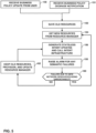
- FIG. 5 is a flowchart illustrating an example method that may be performed by business policy analyzer 104 for addressing failures to intent updates.
- business policy analyzer 104 may receive a business policy update from a user (150).
- business policy analyzer 104 may receive a degrade notification from assurance module 106 (151).
- business policy analyzer 104 saves the old resources (152) for the existing intents.
- Business policy analyzer 104 further determines new resources for the intents (e.g., new intents or existing intents for which resources are degraded) from a resource manager (154) and provisions the new resources.
- Business policy analyzer 104 may then generate stateless intent updates and call intent infrastructure 110 (156). This may cause intent infrastructure 110 to translate the intent changes using intent compiler 114 and to update intent database 118. Furthermore, element configuration service 116 may distribute low-level configuration data updates and update configuration database 120.
- business policy analyzer 104 may determine the failures and attempt to resolve the failures. In particular, business policy analyzer 104 may raise an alarm for semantic failures (158), which may include sending a message to a user representative of the semantic failures. For other failures, business policy analyzer 104 may determine whether the failure is due to unreachable network resources (e.g., elements 14) (160). If a failure is due to new network resources unreachable ("YES" branch of 160), business policy analyzer 104 may update a set of excluded resources, get new resources (154), then again generate stateless intent updates and call intent infrastructure 110 (156).
- unreachable network resources e.g., elements 14
- business policy analyzer 104 may determine to keep the old resources, then again generate stateless intent updates and call intent infrastructure 110 (156).
- FIG. 6 is a flowchart illustrating an example method for concurrent stateless intent provisioning in accordance with the techniques of this disclosure. The method of FIG. 6 may be performed by, e.g., controller device 10 of FIGS. 1 and 2 .
- controller device 10 may receive an intent change (180), e.g., from an application.
- Management module 24 may maintain a difference between a deployed graph model and an undeployed graph model (that is, differences between intents) as a snapshot table in configuration database 40 (182).
- Management module 24 may read the global intent version, where a timestamp of a current time at creation of the global intent may signify the version value (184).
- Translation module 28 may read all dependent vertex changes and generate the low-level model (LLM) (186).
- LLM low-level model
- Management module 24 may determine whether the global intent version is greater than the LLM existing global version (188). If the global intent version is greater than the LLM existing global version ("YES" branch of 188), configuration module 26 may update the LLM objects (190). If the global intent version is not less than the LLM existing global version ("NO" branch of 188), management module 24 may again read the global intent version (184) and rerun translation module 28 and proceed. Configuration module 26 may further generate native configuration data from the LLM objects and commit the native configuration data (192) to elements 14.
- Management module 24 may further determine whether the commit was successful (194). If the commit was not successful ("NO” branch of 194), management module 24 may output a failure indication to the application (196). Otherwise, if the commit was successful ("YES” branch of 194), management module 24 may update the deployed intent data model with the previous undeployed intent data model, update the snapshot, and await new intents.
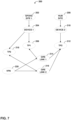
- FIG. 7 is a graph illustrating an example undeployed intent graph 200 following intent changes.
- undeployed intent graph 200 includes spoke site 1 vertex 202, device 1 vertex 204, termination point 1 (TP1) vertex 206, hub site vertex 208, device 2 vertex 210, TP2 vertex 212, GRE link 1 vertex 214, GRE link 2 vertex 216, TP2 vertex 218, and VPN vertex 220.
- a deployed intent graph (not shown) and undeployed intent graph 200 may correspond to an SD-WAN.
- the SD-WAN has site objects, e.g., represented by spoke site 1 vertex 202 and hub site 208.
- the sites can be connected via hub and spoke or full mesh.
- the sites are connected with a GRE overlay, and optionally can have IPSEC enabled.
- There may also be a WAN underlay link across the sites.
- a GRE tunnel may be created.
- translation module 28 may execute a translator named, for example, "compile_gre_link.”
- the available resources may include a site, GRE link, GRE termination point, IPSEC link and termination point, and peer site termination point.
- Translation module 28 may output abstract configuration and corresponding native configuration, e.g., as follows:
- a dynamic VPN may be used, where the dynamic VPN represents a tunnel created between sites only when traffic starts to flow.
- traffic may begin between sites 1 and 2, corresponding respectively to spoke site 1 vertex 202 and hub site 2 vertex 208.
- Controller device 10 may detect the traffic flow and trigger GRE/IPSEC tunnel creation between sites 1 and 2.
- Controller device 10 may add an underlay link between termination points of sites 1 and 2 as an intent update, e.g., (site1 WAN-0 ⁇ -> site2 WAN-0).
- Controller device 10 may also add logical termination points (e.g., interfaces - gr/0/0/0 and st.4000) for overlays in sites 1 and 2.
- Controller device 10 may further add corresponding GRE and IPSEC links between sites 1 and 2.
- the corresponding deployed intent graph may omit GRE link 1 vertex 214 and have a different version of VPN vertex 220. That is, GRE link 1 vertex 214 may have been added relative to the deployed intent graph (corresponding to the example created GRE tunnel), and VPN vertex 214 may have been modified relative to the deployed intent graph. Moreover, GRE link 2 vertex 216 may be deleted from the deployed intent graph.
- management module 24 of controller device 10 may set a state for GRE link 1214 to "created,” a state for VPN vertex 220 to "updated,” and a state for GRE link 2 vertex 216 to “deleted.” After deploying configuration data based on undeployed intent graph 200 to the network, management module 24 may set the states for GRE link 1214 and VPN vertex 220 to "deployed,” and delete GRE link 2 vertex 216 from the graph.
- a failure may result if either or both of devices corresponding to device 1 vertex 204 ("d1") or device 2 vertex 210 ("d2") are not reachable. If either or both of d1 and/or d2 are not reachable, controller device 10 would remove the link between site 1 and site 2 (e.g., site1 WAN-0 ⁇ ->site2 WAN-0).
- the transaction may be maintained for the link between sites 1 and 2.
- controller device 10 would not allow edits in the hub and spoke topology or the VPN network (department) should not be edited.
- Conventional techniques would impact business policy SLA if the VPN is updated.
- FIG. 8 is a flowchart illustrating an example method of configuring network devices according to techniques of this disclosure. The method of FIG. 8 is explained with respect to controller device 10 of FIGS. 1 and 2 , although other devices (e.g., conforming to model 100 of FIG. 4 ) may be configured to perform this or a similar method.
- controller device 10 of FIGS. 1 and 2 although other devices (e.g., conforming to model 100 of FIG. 4 ) may be configured to perform this or a similar method.
- Management module 24 may maintain a deployed graph model in configuration database 40.
- the deployed graph model includes a graph of vertices connected by edges, where the vertices may correspond to network resources such as devices, connections, services, and the like.
- the deployed graph model may represent a set of existing stateful intents.
- Management module 24 may then receive an indication that resources for one or more intents are degraded (221). Management module 24 may determine any existing stateful intents that become degraded as a result of the degraded resources (222).
- Management module 24 may further determine new resources for the stateful intents (224). Management module 24 then provisions the stateful intents using the determined resources (226).
- Management module 24 may then determine whether the provisioning was successful (228). Management module 24 may determine resolutions for failed provisioning (230), e.g., as discussed above with respect to FIG. 5 . For example, for semantic failures, management module 24 may raise an alarm. As another example, for unreachable network resources, management module 24 may update an exclude list and get new resources.
- Management module 24 may cause translation module 28 to compile successful stateful intents into a low-level model (232).
- translation module 28 may determine whether versions of vertices in the undeployed graph model match corresponding change set versions, and if not, execute corresponding reactive mappers to compile corresponding elements of the change set
- Management module 24 may also cause configuration module 26 to configure elements 14 using the low-level model (234). After configuring elements 14 according to the resulting low-level model, management module 24 may update the deployed graph model to the undeployed graph model and await stateful intents.
- the method of FIG. 8 represents an example of a method including determining, by a controller device that manages a plurality of network devices, that one or more stateful intents used to manage the plurality of network devices and represented by a graph model are degraded due to assigned resources for the stateful intents having become degraded; in response to determining that the one or more stateful intents are degraded, determining, by the controller device, resources for the stateful intents, the resources corresponding to vertices of the graph model; provisioning, by the controller device, the stateful intents using the determined resources; determining, by the controller device, whether the provisioning of the stateful intents was successful; compiling, by the controller device, at least one of the stateful intents that was successful into low-level configuration data for at least one network device of the plurality of network devices; and configuring, by the controller device, the at least one network device using the low-level configuration data.
- FIG. 9 is a flowchart representing an example of another method of configuring network devices according to techniques of this disclosure. The method of FIG. 9 is explained with respect to controller device 10 of FIGS. 1 and 2 , although other devices (e.g., conforming to model 100 of FIG. 4 ) may be configured to perform this or a similar method.
- controller device 10 of FIGS. 1 and 2 although other devices (e.g., conforming to model 100 of FIG. 4 ) may be configured to perform this or a similar method.
- management module 24 may maintain a deployed graph model in configuration database 40.
- the deployed graph model includes a graph of vertices connected by edges, where the vertices may correspond to network resources such as devices, connections, services, and the like.
- the deployed graph model may represent a set of existing stateless intents.
- Management module 24 may receive new stateless intents and determine changed stateless intents relative to the existing stateless intents (250). Management module 24 may maintain both a deployed graph model representing the currently deployed stateless intents, as well as an undeployed graph model representing the new stateless intents (252). Management module 24 may set states of vertices in the undeployed graph model using a snapshot table as discussed above (254). For example, management module 24 may set states for created vertices of the undeployed graph model to values representing a "create” state, values for updated vertices relative to the deployed graph model to values representing an "update” state, and values for deleted vertices relative to the deployed graph model to values representing a "delete” state. Management module 24 may also set version values for the vertices (256).
- Management module 24 may then cause translation module 28 to compile the changed stateless intents into a low-level model (258). Management module 24 may also cause configuration unit 26 to configure elements 14 (that is, network devices) using the low-level model (260).
- the method of FIG. 9 represents an example of a method including determining, by a controller device that manages a plurality of network devices, that one or more stateless intents of a deployed graph model including a first set of stateless intents used to manage the plurality of network devices have changed, wherein stateless intents comprise fully declarative descriptions of an intended state of a network including the network devices, state of one or more of the network devices, or state of storage for the network; maintaining, by the controller device, both the deployed graph model and an undeployed graph model including a second set of stateless intents including the one or more changed stateless intents; compiling, by the controller device, the changed stateless intents of the undeployed graph model to generate low-level configuration data for the network devices; and configuring, by the controller device, the network devices using the low-level configuration data.
- processors including one or more microprocessors, digital signal processors (DSPs), application specific integrated circuits (ASICs), field programmable gate arrays (FPGAs), or any other equivalent integrated or discrete logic circuitry, as well as any combination of such components.
- DSPs digital signal processors
- ASICs application specific integrated circuits
- FPGAs field programmable gate arrays
- processors may generally refer to any of the foregoing logic circuitry, alone or in combination with other logic circuitry, or any other equivalent circuitry.
- a control unit comprising hardware may also perform one or more of the techniques of this disclosure.
- Such hardware, software, and firmware may be implemented within the same device or within separate devices to support the various operations and functions described in this disclosure.
- any of the described units, modules or components may be implemented together or separately as discrete but interoperable logic devices. Depiction of different features as modules or units is intended to highlight different functional aspects and does not necessarily imply that such modules or units must be realized by separate hardware or software components. Rather, functionality associated with one or more modules or units may be performed by separate hardware or software components, or integrated within common or separate hardware or software components.
- Computer-readable medium such as a computer-readable storage medium, containing instructions. Instructions embedded or encoded in a computer-readable medium may cause a programmable processor, or other processor, to perform the method, e.g., when the instructions are executed.
- Computer-readable media may include non-transitory computer-readable storage media and transient communication media such as carrier signals and transmission media.
- Computer readable storage media which is tangible and non-transitory, may include random access memory (RAM), read only memory (ROM), programmable read only memory (PROM), erasable programmable read only memory (EPROM), electronically erasable programmable read only memory (EEPROM), flash memory, a hard disk, a CD-ROM, a floppy disk, a cassette, magnetic media, optical media, or other computer-readable storage media.
- RAM random access memory
- ROM read only memory
- PROM programmable read only memory
- EPROM erasable programmable read only memory
- EEPROM electronically erasable programmable read only memory
- flash memory a hard disk, a CD-ROM, a floppy disk, a cassette, magnetic media, optical media, or other computer-readable storage media.
- the controller device includes one or more processing units implemented in circuitry and configured to determine that one or more stateless intents of a deployed graph model including a first set of stateless intents used to manage the plurality of network devices have changed, wherein stateless intents comprise fully declarative descriptions of an intended state of a network including the network devices, state of one or more of the network devices, or state of storage for the network; maintain both the deployed graph model and an undeployed graph model including a second set of stateless intents including the one or more changed stateless intents; compile the changed stateless intents of the undeployed graph model to generate low-level configuration data for the network devices; and configure the network devices using the low-level configuration data.
Landscapes
- Engineering & Computer Science (AREA)
- Computer Networks & Wireless Communication (AREA)
- Signal Processing (AREA)
- Data Mining & Analysis (AREA)
- Quality & Reliability (AREA)
- Data Exchanges In Wide-Area Networks (AREA)
Claims (13)
- Procédé comprenant les étapes suivantes :déterminer, par un dispositif contrôleur (10) qui gère une pluralité de dispositifs de réseau (14), qu'une ou plusieurs intentions sans état d'un modèle de graphe déployé (60) comprenant un premier ensemble d'intentions sans état utilisées pour gérer la pluralité de dispositifs de réseau ont changé, où les intentions sans état comprennent des descriptions entièrement déclaratives d'un état prévu d'un réseau comprenant les dispositifs de réseau, l'état d'un ou de plusieurs des dispositifs de réseau, ou l'état du stockage pour le réseau ;maintenir, par le dispositif contrôleur, à la fois le modèle de graphe déployé et un modèle de graphe non déployé comprenant un deuxième ensemble d'intentions sans état comprenant les une ou plusieurs intentions sans état modifiées, des valeurs de version pour le modèle de graphe déployé et le modèle de graphe non déployé, des valeurs de version pour les sommets du modèle de graphe déployé, et des valeurs de version pour les sommets du modèle de graphe non déployé ;déterminer, par le dispositif contrôleur, si une version globale existante est supérieure à une nouvelle version globale ;si la version globale existante est supérieure à la nouvelle version globale :recompiler, par le dispositif contrôleur, les intentions sans état modifiées du modèle de graphe non déployé afin de générer des données de configuration de bas niveau pour les dispositifs de réseau, etconfigurer, par le dispositif contrôleur, les dispositifs de réseau à l'aide des données de configuration de bas niveau ; ousi la version globale existante n'est pas supérieure à la nouvelle version globale, mettre à jour les ressources de bas niveau et la valeur de la version pour le modèle de graphe déployé.
- Procédé selon la revendication 1, dans lequel la compilation comprend la compilation de deux, ou davantage, des intentions sans état modifiées qui ont été modifiées simultanément de sorte que les deux, ou davantage, des intentions sans état modifiées ne s'invalident pas l'une l'autre.
- Procédé selon la revendication 1 ou la revendication 2, comprenant en outre le remplacement du modèle de graphe déployé par le modèle de graphe non déployé après la configuration des dispositifs de réseau, et l'envoi d'un message de réponse de déploiement.
- Procédé selon l'une quelconque des revendications précédentes, comprenant en outre les étapes suivantes :maintenir une table d'instantanés comprenant une liste d'identificateurs universels uniques (UUID) des sommets du modèle de graphe non déployé ;lorsqu'un premier sommet des sommets du modèle de graphe non déployé est créé, définir un état pour le premier sommet dans la table d'instantanés à une valeur représentant un état de création ;lorsqu'un deuxième sommet des sommets du modèle de graphe non déployé est mis à jour, définir un état pour le deuxième sommet dans la table d'instantanés à une valeur représentant un état de mise à jour ; etlorsqu'un troisième sommet des sommets du modèle de graphe non déployé est supprimé, définir un état pour le troisième sommet dans la table d'instantanés à une valeur représentant un état de suppression.
- Procédé selon la revendication 4, comprenant en outre, après avoir déployé le modèle de graphe non déployé, les étapes suivantes :mettre à jour l'état du premier sommet à une valeur représentant un état déployé ;mettre à jour l'état du deuxième sommet à la valeur représentant l'état déployé ; etsupprimer le troisième sommet.
- Procédé selon l'une quelconque des revendications précédentes, dans lequel la compilation des intentions sans état modifiés comprend en outre la compilation des intentions sans état dépendantes qui dépendent d'une ou de plusieurs des intentions sans état modifiées selon un graphe de dépendance.
- Dispositif contrôleur (10) qui gère une pluralité de dispositifs de réseau (14), le dispositif contrôleur comprenant une ou plusieurs unités de traitement mises en œuvre dans des circuits et configurées pour :déterminer qu'une ou plusieurs intentions sans état d'un modèle de graphe déployé (60) comprenant un premier ensemble d'intentions sans état utilisées pour gérer la pluralité de dispositifs de réseau ont changé, où les intentions sans état comprennent des descriptions entièrement déclaratives d'un état prévu d'un réseau comprenant les dispositifs de réseau, l'état d'un ou de plusieurs des dispositifs de réseau, ou l'état du stockage pour le réseau ;maintenir à la fois le modèle de graphe déployé et un modèle de graphe non déployé comprenant un deuxième ensemble d'intentions sans état comprenant les une ou plusieurs intentions sans état modifiées, des valeurs de version pour le modèle de graphe déployé et le modèle de graphe non déployé, des valeurs de version pour les sommets du modèle de graphe déployé, et des valeurs de version pour les sommets du modèle de graphe non déployé ;déterminer si une version globale existante est supérieure à une nouvelle version globale ;si la version globale existante est supérieure à la nouvelle version globale :recompiler les intentions sans état modifiées du modèle de graphe non déployé afin de générer des données de configuration de bas niveau pour les dispositifs de réseau, etconfigurer les dispositifs de réseau à l'aide des données de configuration de bas niveau ; ousi la version globale existante n'est pas supérieure à la nouvelle version globale, mettre à jour les ressources de bas niveau et la valeur de la version pour le modèle de graphe déployé.
- Dispositif contrôleur selon la revendication 7, dans lequel les unités de traitement sont configurées pour compiler deux, ou davantage, des intentions sans état modifiées qui ont été modifiées simultanément de sorte que les deux, ou davantage, des intentions sans état modifiées ne s'invalident pas l'une l'autre.
- Dispositif contrôleur selon la revendication 7, dans lequel une ou plusieurs unités de traitement sont en outre configurées pour remplacer le modèle de graphe déployé par le modèle de graphe non déployé après avoir configuré les dispositifs de réseau, et pour envoyer un message de réponse de déploiement.
- Dispositif contrôleur selon la revendication 7, dans lequel les unités de traitement sont en outre configurées pour :maintenir une table d'instantanés comprenant une liste d'identificateurs universels uniques (UUID) des sommets du modèle de graphe non déployé ;lorsqu'un premier sommet des sommets du modèle de graphe non déployé est créé, définir un état pour le premier sommet dans la table d'instantanés à une valeur représentant un état de création ;lorsqu'un deuxième sommet des sommets du modèle de graphe non déployé est mis à jour, définir un état pour le deuxième sommet dans la table d'instantanés à une valeur représentant un état de mise à jour ; etlorsqu'un troisième sommet des sommets du modèle de graphe non déployé est supprimé, définir un état pour le troisième sommet dans la table d'instantanés à une valeur représentant un état de suppression.
- Dispositif contrôleur selon la revendication 10, dans lequel les unités de traitement sont en outre configurées pour, après avoir déployé le modèle de graphe non déployé :mettre à jour l'état du premier sommet à une valeur représentant un état déployé ;mettre à jour l'état du deuxième sommet à la valeur représentant l'état déployé ; etsupprimer le troisième sommet.
- Dispositif contrôleur selon la revendication 7, dans lequel, pour compiler les intentions sans état modifiées, les unités de traitement sont en outre configurées pour compiler les intentions sans état dépendantes qui dépendent d'une ou de plusieurs des intentions sans état modifiées conformément à un graphe de dépendance.
- Support lisible par ordinateur comprenant des instructions pour amener un processeur d'un dispositif contrôleur qui gère une pluralité de dispositifs de réseau à exécuter le procédé de l'une quelconque des revendications 1 à 6.
Priority Applications (1)
| Application Number | Priority Date | Filing Date | Title |
|---|---|---|---|
| EP23174612.4A EP4236239A3 (fr) | 2019-03-29 | 2019-06-21 | Prise en charge de la concurrence pour modèles de configuration de haut niveau basés sur des graphiques |
Applications Claiming Priority (1)
| Application Number | Priority Date | Filing Date | Title |
|---|---|---|---|
| US16/370,243 US10897396B2 (en) | 2019-03-29 | 2019-03-29 | Supporting concurrency for graph-based high level configuration models |
Related Child Applications (1)
| Application Number | Title | Priority Date | Filing Date |
|---|---|---|---|
| EP23174612.4A Division EP4236239A3 (fr) | 2019-03-29 | 2019-06-21 | Prise en charge de la concurrence pour modèles de configuration de haut niveau basés sur des graphiques |
Publications (2)
| Publication Number | Publication Date |
|---|---|
| EP3716532A1 EP3716532A1 (fr) | 2020-09-30 |
| EP3716532B1 true EP3716532B1 (fr) | 2023-06-21 |
Family
ID=67001649
Family Applications (2)
| Application Number | Title | Priority Date | Filing Date |
|---|---|---|---|
| EP19181698.2A Active EP3716532B1 (fr) | 2019-03-29 | 2019-06-21 | Prise en charge de la concurrence pour modèles de configuration de haut niveau basés sur des graphiques |
| EP23174612.4A Pending EP4236239A3 (fr) | 2019-03-29 | 2019-06-21 | Prise en charge de la concurrence pour modèles de configuration de haut niveau basés sur des graphiques |
Family Applications After (1)
| Application Number | Title | Priority Date | Filing Date |
|---|---|---|---|
| EP23174612.4A Pending EP4236239A3 (fr) | 2019-03-29 | 2019-06-21 | Prise en charge de la concurrence pour modèles de configuration de haut niveau basés sur des graphiques |
Country Status (3)
| Country | Link |
|---|---|
| US (2) | US10897396B2 (fr) |
| EP (2) | EP3716532B1 (fr) |
| CN (2) | CN113810236A (fr) |
Families Citing this family (18)
| Publication number | Priority date | Publication date | Assignee | Title |
|---|---|---|---|---|
| US10389573B2 (en) | 2014-11-14 | 2019-08-20 | Apstra, Inc. | Configuring a network |
| US10063428B1 (en) | 2015-06-30 | 2018-08-28 | Apstra, Inc. | Selectable declarative requirement levels |
| US10313206B1 (en) | 2015-12-23 | 2019-06-04 | Apstra, Inc. | Verifying service status |
| US10374872B2 (en) | 2016-05-24 | 2019-08-06 | Apstra, Inc. | Configuring system resources for different reference architectures |
| US11567994B2 (en) | 2017-01-24 | 2023-01-31 | Apstra, Inc. | Configuration, telemetry, and analytics of a computer infrastructure using a graph model |
| US11368410B2 (en) * | 2019-03-15 | 2022-06-21 | Mojatatu Networks | System and method for scaling analytics collection |
| US10992543B1 (en) | 2019-03-21 | 2021-04-27 | Apstra, Inc. | Automatically generating an intent-based network model of an existing computer network |
| US10841182B2 (en) | 2019-03-29 | 2020-11-17 | Juniper Networks, Inc. | Supporting near real time service level agreements |
| US10897396B2 (en) * | 2019-03-29 | 2021-01-19 | Juniper Networks, Inc. | Supporting concurrency for graph-based high level configuration models |
| US11075805B1 (en) * | 2019-04-24 | 2021-07-27 | Juniper Networks, Inc. | Business policy management for self-driving network |
| US11573961B2 (en) * | 2019-07-10 | 2023-02-07 | Microsoft Technology Licensing, Llc | Delta graph traversing system |
| US11283691B1 (en) * | 2020-10-21 | 2022-03-22 | Juniper Networks, Inc. | Model driven intent policy conflict detection and resolution through graph analysis |
| US11799725B2 (en) * | 2020-12-22 | 2023-10-24 | Nokia Solutions And Networks Oy | Intent-based networking using reconstruction of intents |
| US11539592B2 (en) * | 2020-12-22 | 2022-12-27 | Nokia Solutions And Networks Oy | Intent-based networking using network change validation |
| EP4050851A1 (fr) | 2021-02-26 | 2022-08-31 | Nokia Solutions and Networks Oy | Transformation des expressions d'intention en commandes et configurations |
| US20220393942A1 (en) * | 2021-04-26 | 2022-12-08 | NetBrain Technologies, Inc. | Network intent management and automation |
| US11451440B1 (en) | 2021-09-21 | 2022-09-20 | Juniper Networks, Inc. | Sharing configuration resources for network devices among applications |
| EP4340312A1 (fr) * | 2022-09-16 | 2024-03-20 | Juniper Networks, Inc. | Traduction d'un modèle de politique d'intention source en un modèle de politique d'intention cible |
Family Cites Families (73)
| Publication number | Priority date | Publication date | Assignee | Title |
|---|---|---|---|---|
| US5933642A (en) | 1995-04-17 | 1999-08-03 | Ricoh Corporation | Compiling system and method for reconfigurable computing |
| US5870559A (en) | 1996-10-15 | 1999-02-09 | Mercury Interactive | Software system and associated methods for facilitating the analysis and management of web sites |
| US6078744A (en) | 1997-08-01 | 2000-06-20 | Sun Microsystems | Method and apparatus for improving compiler performance during subsequent compilations of a source program |
| US6041053A (en) | 1997-09-18 | 2000-03-21 | Microsfot Corporation | Technique for efficiently classifying packets using a trie-indexed hierarchy forest that accommodates wildcards |
| US6298321B1 (en) | 1998-11-23 | 2001-10-02 | Microsoft Corporation | Trie compression using substates and utilizing pointers to replace or merge identical, reordered states |
| US6678646B1 (en) | 1999-12-14 | 2004-01-13 | Atmel Corporation | Method for implementing a physical design for a dynamically reconfigurable logic circuit |
| US6973488B1 (en) | 2000-03-31 | 2005-12-06 | Intel Corporation | Providing policy information to a remote device |
| US7209473B1 (en) | 2000-08-18 | 2007-04-24 | Juniper Networks, Inc. | Method and apparatus for monitoring and processing voice over internet protocol packets |
| US8195779B2 (en) | 2002-09-27 | 2012-06-05 | Broadcom Corporation | System and method of a management information base (MIB) autocast in a communications network |
| US7953779B1 (en) | 2002-10-08 | 2011-05-31 | Trilogy Development Group, Inc. | Configuration representation and modeling using configuration spaces |
| US7457296B2 (en) | 2004-09-30 | 2008-11-25 | Intel Corporation | Method and apparatus for sorting packets in packet schedulers using a connected trie data structure |
| FR2902954B1 (fr) | 2006-06-21 | 2008-10-17 | Netasq Sa | Systeme et procede de stockage d'un inventaire des systemes et/ou services presents sur un reseau de communication |
| US8571882B1 (en) * | 2006-07-05 | 2013-10-29 | Ronald J. Teitelbaum | Peer to peer database |
| US20080294777A1 (en) * | 2007-05-25 | 2008-11-27 | Alexei Karve | Method and apparatus for template-based provisioning in a service delivery environment |
| JP5119902B2 (ja) | 2007-12-19 | 2013-01-16 | 富士通セミコンダクター株式会社 | 動的再構成支援プログラム、動的再構成支援方法、動的再構成回路、動的再構成支援装置および動的再構成システム |
| US8572717B2 (en) | 2008-10-09 | 2013-10-29 | Juniper Networks, Inc. | Dynamic access control policy with port restrictions for a network security appliance |
| US8069374B2 (en) | 2009-02-27 | 2011-11-29 | Microsoft Corporation | Fingerprinting event logs for system management troubleshooting |
| US9117071B2 (en) | 2009-06-03 | 2015-08-25 | Apple Inc. | Methods and apparatuses for secure compilation |
| US8677329B2 (en) | 2009-06-03 | 2014-03-18 | Apple Inc. | Methods and apparatuses for a compiler server |
| US8719226B1 (en) * | 2009-07-16 | 2014-05-06 | Juniper Networks, Inc. | Database version control |
| US8572591B2 (en) | 2010-06-15 | 2013-10-29 | Microsoft Corporation | Dynamic adaptive programming |
| US8838653B2 (en) | 2010-11-01 | 2014-09-16 | Cisco Technology, Inc. | Translating an object-oriented data model to a YANG data model |
| US9489184B2 (en) | 2011-12-30 | 2016-11-08 | Oracle International Corporation | Adaptive selection of programming language versions for compilation of software programs |
| US9979738B2 (en) | 2012-01-23 | 2018-05-22 | Hrl Laboratories, Llc | System and method to detect attacks on mobile wireless networks based on motif analysis |
| CN103034617B (zh) | 2012-12-13 | 2015-09-30 | 深圳市同创国芯电子有限公司 | 用于实现可重构系统配置信息存储的缓存结构和管理方法 |
| US8976697B2 (en) * | 2012-12-17 | 2015-03-10 | Broadcom Corporation | Network status mapping |
| US9596141B2 (en) * | 2013-03-15 | 2017-03-14 | Cisco Technology, Inc. | Representing software defined networks using a programmable graph model |
| US9727339B2 (en) | 2013-07-18 | 2017-08-08 | Nvidia Corporation | Method and system for distributed shader optimization |
| US9755960B2 (en) | 2013-09-30 | 2017-09-05 | Juniper Networks, Inc. | Session-aware service chaining within computer networks |
| US10523502B2 (en) | 2014-05-29 | 2019-12-31 | Abb Schweiz Ag | Method and system for configuration of devices of a control system |
| US9705815B2 (en) | 2014-06-27 | 2017-07-11 | Juniper Networks, Inc. | Graph database for services planning and configuration in network services domain |
| CN104156230B (zh) * | 2014-07-11 | 2017-08-29 | 国家电网公司 | 基于调试系统数据对象化技术的自动化红黑图实现方法 |
| US10050842B2 (en) * | 2014-07-23 | 2018-08-14 | Cisco Technology, Inc. | Network control and management using semantic reasoners in a network environment |
| US10200258B2 (en) | 2014-08-14 | 2019-02-05 | Juniper Networks, Inc. | Transaction integrity for network services configuration |
| US9436443B2 (en) | 2014-08-28 | 2016-09-06 | At&T Intellectual Property I, L.P. | Software defined network controller |
| US9762450B2 (en) | 2014-09-04 | 2017-09-12 | Accenture Global Services Limited | System architecture for cloud-platform infrastructure layouts |
| US9806991B2 (en) * | 2015-01-21 | 2017-10-31 | Cisco Technology, Inc. | Rendering network policy and monitoring compliance |
| US10084670B2 (en) | 2015-03-12 | 2018-09-25 | International Business Machines Corporation | Network node on-demand link resources |
| CN104699508B (zh) * | 2015-03-25 | 2017-08-22 | 南京大学 | 云计算平台中快速部署和更新虚拟环境系统及其方法 |
| US9715380B2 (en) | 2015-05-26 | 2017-07-25 | Cisco Technology, Inc. | Techniques for enabling dynamic update of device data models |
| US10187321B2 (en) | 2015-08-19 | 2019-01-22 | Cisco Technology, Inc. | Dynamic VPN policy model with encryption and traffic engineering resolution |
| US9942934B2 (en) | 2015-11-04 | 2018-04-10 | Motorola Mobility Llc | Wireless ad hoc network assembly using network coding |
| US10102172B1 (en) | 2015-12-27 | 2018-10-16 | Altera Corporation | Method and apparatus for performing a single pass compilation for systems with dynamically reconfigurable logic blocks |
| US10374872B2 (en) | 2016-05-24 | 2019-08-06 | Apstra, Inc. | Configuring system resources for different reference architectures |
| US10148506B1 (en) | 2016-06-28 | 2018-12-04 | Juniper Networks, Inc. | Network configuration service discovery |
| US10200248B1 (en) | 2016-06-30 | 2019-02-05 | Juniper Networks, Inc. | Translating high-level configuration instructions to low-level device configuration |
| US10783183B2 (en) | 2016-11-30 | 2020-09-22 | At&T Intellectual Property I, L.P. | Systems and methods for driving graph structure and behavior using models |
| US10374888B2 (en) | 2016-12-14 | 2019-08-06 | At&T Intellectual Property I, L.P. | Scheduler for upgrading access point devices efficiently |
| US10374886B1 (en) | 2016-12-30 | 2019-08-06 | Juniper Networks, Inc. | Processing multiple parallel high level configuration changes for managed network devices |
| US10278112B1 (en) | 2016-12-30 | 2019-04-30 | Juniper Networks, Inc. | Resolving out-of-band configuration changes to high-level service configuration for managed network devices |
| US11567994B2 (en) | 2017-01-24 | 2023-01-31 | Apstra, Inc. | Configuration, telemetry, and analytics of a computer infrastructure using a graph model |
| US10489358B2 (en) | 2017-02-15 | 2019-11-26 | Ca, Inc. | Schemas to declare graph data models |
| US10567223B1 (en) | 2017-03-07 | 2020-02-18 | Juniper Networks, Inc. | Optimistic concurrency control for managed network devices |
| US20170187577A1 (en) | 2017-03-14 | 2017-06-29 | Nuviso Networks Inc | System for configuring network devices |
| US10516761B1 (en) | 2017-03-17 | 2019-12-24 | Juniper Networks, Inc. | Configuring and managing network devices using program overlay on Yang-based graph database |
| US10937214B2 (en) | 2017-03-22 | 2021-03-02 | Google Llc | System and method for merging maps |
| US10558542B1 (en) | 2017-03-31 | 2020-02-11 | Juniper Networks, Inc. | Intelligent device role discovery |
| US10810210B2 (en) | 2017-05-12 | 2020-10-20 | Battelle Memorial Institute | Performance and usability enhancements for continuous subgraph matching queries on graph-structured data |
| US20180351806A1 (en) | 2017-05-31 | 2018-12-06 | Cisco Technology, Inc. | Intent specification checks for inconsistencies |
| KR20190004495A (ko) | 2017-07-04 | 2019-01-14 | 삼성에스디에스 주식회사 | 챗봇을 이용한 태스크 처리 방법, 장치 및 시스템 |
| CN109271621B (zh) | 2017-07-18 | 2023-04-18 | 腾讯科技(北京)有限公司 | 语义消歧处理方法、装置及其设备 |
| CN107577709B (zh) * | 2017-07-31 | 2020-08-25 | 国网安徽省电力公司信息通信分公司 | 一种信息系统资源模型的图形化管理方法 |
| US10382265B1 (en) | 2017-08-28 | 2019-08-13 | Juniper Networks, Inc. | Reversible yang-based translators |
| US10554500B2 (en) | 2017-10-04 | 2020-02-04 | Futurewei Technologies, Inc. | Modeling access networks as trees in software-defined network controllers |
| US10756983B2 (en) * | 2017-12-08 | 2020-08-25 | Apstra, Inc. | Intent-based analytics |
| JP6744882B2 (ja) * | 2018-02-26 | 2020-08-19 | 株式会社日立製作所 | 行動パターン探索システム、および行動パターン探索方法 |
| CN108667666A (zh) * | 2018-05-20 | 2018-10-16 | 北京工业大学 | 一种基于可视化技术的智能运维方法及其系统 |
| US11140049B2 (en) | 2018-09-07 | 2021-10-05 | Juniper Networks, Inc. | Dynamic intent assurance and programmability in computer networks |
| US10892952B2 (en) | 2019-02-21 | 2021-01-12 | Juniper Networks, Inc. | Supporting compilation and extensibility on unified graph-based intent models |
| US10992543B1 (en) * | 2019-03-21 | 2021-04-27 | Apstra, Inc. | Automatically generating an intent-based network model of an existing computer network |
| US10841182B2 (en) | 2019-03-29 | 2020-11-17 | Juniper Networks, Inc. | Supporting near real time service level agreements |
| US10897396B2 (en) | 2019-03-29 | 2021-01-19 | Juniper Networks, Inc. | Supporting concurrency for graph-based high level configuration models |
| US11165647B2 (en) | 2019-06-28 | 2021-11-02 | Juniper Networks, Inc. | Managing multiple semantic versions of device configuration schemas |
-
2019
- 2019-03-29 US US16/370,243 patent/US10897396B2/en active Active
- 2019-06-21 EP EP19181698.2A patent/EP3716532B1/fr active Active
- 2019-06-21 EP EP23174612.4A patent/EP4236239A3/fr active Pending
- 2019-09-29 CN CN202111283431.XA patent/CN113810236A/zh active Pending
- 2019-09-29 CN CN201910936240.5A patent/CN111756564B/zh active Active
-
2021
- 2021-01-15 US US17/248,268 patent/US11689419B2/en active Active
Also Published As
| Publication number | Publication date |
|---|---|
| US20200313957A1 (en) | 2020-10-01 |
| CN113810236A (zh) | 2021-12-17 |
| US10897396B2 (en) | 2021-01-19 |
| US11689419B2 (en) | 2023-06-27 |
| CN111756564A (zh) | 2020-10-09 |
| EP4236239A3 (fr) | 2023-09-27 |
| CN111756564B (zh) | 2021-10-08 |
| EP4236239A2 (fr) | 2023-08-30 |
| US20210144053A1 (en) | 2021-05-13 |
| EP3716532A1 (fr) | 2020-09-30 |
Similar Documents
| Publication | Publication Date | Title |
|---|---|---|
| EP3716532B1 (fr) | Prise en charge de la concurrence pour modèles de configuration de haut niveau basés sur des graphiques | |
| EP3716534B1 (fr) | Prise en charge d'accords de niveau de service en temps quasi réel | |
| US10892952B2 (en) | Supporting compilation and extensibility on unified graph-based intent models | |
| US11929886B2 (en) | Model driven intent policy conflict detection and resolution through graph analysis | |
| US11165647B2 (en) | Managing multiple semantic versions of device configuration schemas | |
| US10278112B1 (en) | Resolving out-of-band configuration changes to high-level service configuration for managed network devices | |
| US10897395B2 (en) | Programmable configlets through opaque intents in graph based intent controllers | |
| CN112104473B (zh) | 基于图形的意图控制器中的可编程配置模板 | |
| US11736410B1 (en) | Synchronizing device resources for element management systems | |
| EP3952212B1 (fr) | Utilisation d'un modèle mathématique de dépendance de ressources programmable pour effectuer une analyse des causes profondes | |
| US11582099B1 (en) | Predictive pipeline analytics for a network management system | |
| US11700181B2 (en) | Topology compiler for network management system |
Legal Events
| Date | Code | Title | Description |
|---|---|---|---|
| PUAI | Public reference made under article 153(3) epc to a published international application that has entered the european phase |
Free format text: ORIGINAL CODE: 0009012 |
|
| STAA | Information on the status of an ep patent application or granted ep patent |
Free format text: STATUS: THE APPLICATION HAS BEEN PUBLISHED |
|
| AK | Designated contracting states |
Kind code of ref document: A1 Designated state(s): AL AT BE BG CH CY CZ DE DK EE ES FI FR GB GR HR HU IE IS IT LI LT LU LV MC MK MT NL NO PL PT RO RS SE SI SK SM TR |
|
| AX | Request for extension of the european patent |
Extension state: BA ME |
|
| STAA | Information on the status of an ep patent application or granted ep patent |
Free format text: STATUS: REQUEST FOR EXAMINATION WAS MADE |
|
| 17P | Request for examination filed |
Effective date: 20210329 |
|
| RBV | Designated contracting states (corrected) |
Designated state(s): AL AT BE BG CH CY CZ DE DK EE ES FI FR GB GR HR HU IE IS IT LI LT LU LV MC MK MT NL NO PL PT RO RS SE SI SK SM TR |
|
| REG | Reference to a national code |
Ref country code: DE Ref legal event code: R079 Ref document number: 602019031249 Country of ref document: DE Free format text: PREVIOUS MAIN CLASS: H04L0012240000 Ipc: H04L0041085000 |
|
| GRAP | Despatch of communication of intention to grant a patent |
Free format text: ORIGINAL CODE: EPIDOSNIGR1 |
|
| STAA | Information on the status of an ep patent application or granted ep patent |
Free format text: STATUS: GRANT OF PATENT IS INTENDED |
|
| RIC1 | Information provided on ipc code assigned before grant |
Ipc: H04L 41/085 20220101AFI20221215BHEP |
|
| INTG | Intention to grant announced |
Effective date: 20230112 |
|
| GRAS | Grant fee paid |
Free format text: ORIGINAL CODE: EPIDOSNIGR3 |
|
| GRAA | (expected) grant |
Free format text: ORIGINAL CODE: 0009210 |
|
| STAA | Information on the status of an ep patent application or granted ep patent |
Free format text: STATUS: THE PATENT HAS BEEN GRANTED |
|
| AK | Designated contracting states |
Kind code of ref document: B1 Designated state(s): AL AT BE BG CH CY CZ DE DK EE ES FI FR GB GR HR HU IE IS IT LI LT LU LV MC MK MT NL NO PL PT RO RS SE SI SK SM TR |
|
| P01 | Opt-out of the competence of the unified patent court (upc) registered |
Effective date: 20230520 |
|
| REG | Reference to a national code |
Ref country code: CH Ref legal event code: EP |
|
| REG | Reference to a national code |
Ref country code: DE Ref legal event code: R096 Ref document number: 602019031249 Country of ref document: DE |
|
| REG | Reference to a national code |
Ref country code: AT Ref legal event code: REF Ref document number: 1581722 Country of ref document: AT Kind code of ref document: T Effective date: 20230715 |
|
| REG | Reference to a national code |
Ref country code: IE Ref legal event code: FG4D |
|
| PGFP | Annual fee paid to national office [announced via postgrant information from national office to epo] |
Ref country code: DE Payment date: 20230623 Year of fee payment: 5 |
|
| REG | Reference to a national code |
Ref country code: LT Ref legal event code: MG9D |
|
| REG | Reference to a national code |
Ref country code: NL Ref legal event code: MP Effective date: 20230621 |
|
| PG25 | Lapsed in a contracting state [announced via postgrant information from national office to epo] |
Ref country code: SE Free format text: LAPSE BECAUSE OF FAILURE TO SUBMIT A TRANSLATION OF THE DESCRIPTION OR TO PAY THE FEE WITHIN THE PRESCRIBED TIME-LIMIT Effective date: 20230621 Ref country code: NO Free format text: LAPSE BECAUSE OF FAILURE TO SUBMIT A TRANSLATION OF THE DESCRIPTION OR TO PAY THE FEE WITHIN THE PRESCRIBED TIME-LIMIT Effective date: 20230921 |
|
| PGFP | Annual fee paid to national office [announced via postgrant information from national office to epo] |
Ref country code: GB Payment date: 20230720 Year of fee payment: 5 |
|
| REG | Reference to a national code |
Ref country code: AT Ref legal event code: MK05 Ref document number: 1581722 Country of ref document: AT Kind code of ref document: T Effective date: 20230621 |
|
| PG25 | Lapsed in a contracting state [announced via postgrant information from national office to epo] |
Ref country code: RS Free format text: LAPSE BECAUSE OF FAILURE TO SUBMIT A TRANSLATION OF THE DESCRIPTION OR TO PAY THE FEE WITHIN THE PRESCRIBED TIME-LIMIT Effective date: 20230621 Ref country code: NL Free format text: LAPSE BECAUSE OF FAILURE TO SUBMIT A TRANSLATION OF THE DESCRIPTION OR TO PAY THE FEE WITHIN THE PRESCRIBED TIME-LIMIT Effective date: 20230621 Ref country code: LV Free format text: LAPSE BECAUSE OF FAILURE TO SUBMIT A TRANSLATION OF THE DESCRIPTION OR TO PAY THE FEE WITHIN THE PRESCRIBED TIME-LIMIT Effective date: 20230621 Ref country code: LT Free format text: LAPSE BECAUSE OF FAILURE TO SUBMIT A TRANSLATION OF THE DESCRIPTION OR TO PAY THE FEE WITHIN THE PRESCRIBED TIME-LIMIT Effective date: 20230621 Ref country code: HR Free format text: LAPSE BECAUSE OF FAILURE TO SUBMIT A TRANSLATION OF THE DESCRIPTION OR TO PAY THE FEE WITHIN THE PRESCRIBED TIME-LIMIT Effective date: 20230621 Ref country code: GR Free format text: LAPSE BECAUSE OF FAILURE TO SUBMIT A TRANSLATION OF THE DESCRIPTION OR TO PAY THE FEE WITHIN THE PRESCRIBED TIME-LIMIT Effective date: 20230922 |
|
| PGFP | Annual fee paid to national office [announced via postgrant information from national office to epo] |
Ref country code: FR Payment date: 20230720 Year of fee payment: 5 |
|
| PG25 | Lapsed in a contracting state [announced via postgrant information from national office to epo] |
Ref country code: FI Free format text: LAPSE BECAUSE OF FAILURE TO SUBMIT A TRANSLATION OF THE DESCRIPTION OR TO PAY THE FEE WITHIN THE PRESCRIBED TIME-LIMIT Effective date: 20230621 |
|
| PG25 | Lapsed in a contracting state [announced via postgrant information from national office to epo] |
Ref country code: SK Free format text: LAPSE BECAUSE OF FAILURE TO SUBMIT A TRANSLATION OF THE DESCRIPTION OR TO PAY THE FEE WITHIN THE PRESCRIBED TIME-LIMIT Effective date: 20230621 |
|
| PG25 | Lapsed in a contracting state [announced via postgrant information from national office to epo] |
Ref country code: ES Free format text: LAPSE BECAUSE OF FAILURE TO SUBMIT A TRANSLATION OF THE DESCRIPTION OR TO PAY THE FEE WITHIN THE PRESCRIBED TIME-LIMIT Effective date: 20230621 |
|
| PG25 | Lapsed in a contracting state [announced via postgrant information from national office to epo] |
Ref country code: IS Free format text: LAPSE BECAUSE OF FAILURE TO SUBMIT A TRANSLATION OF THE DESCRIPTION OR TO PAY THE FEE WITHIN THE PRESCRIBED TIME-LIMIT Effective date: 20231021 |
|
| PG25 | Lapsed in a contracting state [announced via postgrant information from national office to epo] |
Ref country code: SM Free format text: LAPSE BECAUSE OF FAILURE TO SUBMIT A TRANSLATION OF THE DESCRIPTION OR TO PAY THE FEE WITHIN THE PRESCRIBED TIME-LIMIT Effective date: 20230621 Ref country code: SK Free format text: LAPSE BECAUSE OF FAILURE TO SUBMIT A TRANSLATION OF THE DESCRIPTION OR TO PAY THE FEE WITHIN THE PRESCRIBED TIME-LIMIT Effective date: 20230621 Ref country code: RO Free format text: LAPSE BECAUSE OF FAILURE TO SUBMIT A TRANSLATION OF THE DESCRIPTION OR TO PAY THE FEE WITHIN THE PRESCRIBED TIME-LIMIT Effective date: 20230621 Ref country code: PT Free format text: LAPSE BECAUSE OF FAILURE TO SUBMIT A TRANSLATION OF THE DESCRIPTION OR TO PAY THE FEE WITHIN THE PRESCRIBED TIME-LIMIT Effective date: 20231023 Ref country code: IS Free format text: LAPSE BECAUSE OF FAILURE TO SUBMIT A TRANSLATION OF THE DESCRIPTION OR TO PAY THE FEE WITHIN THE PRESCRIBED TIME-LIMIT Effective date: 20231021 Ref country code: ES Free format text: LAPSE BECAUSE OF FAILURE TO SUBMIT A TRANSLATION OF THE DESCRIPTION OR TO PAY THE FEE WITHIN THE PRESCRIBED TIME-LIMIT Effective date: 20230621 Ref country code: EE Free format text: LAPSE BECAUSE OF FAILURE TO SUBMIT A TRANSLATION OF THE DESCRIPTION OR TO PAY THE FEE WITHIN THE PRESCRIBED TIME-LIMIT Effective date: 20230621 Ref country code: CZ Free format text: LAPSE BECAUSE OF FAILURE TO SUBMIT A TRANSLATION OF THE DESCRIPTION OR TO PAY THE FEE WITHIN THE PRESCRIBED TIME-LIMIT Effective date: 20230621 Ref country code: AT Free format text: LAPSE BECAUSE OF FAILURE TO SUBMIT A TRANSLATION OF THE DESCRIPTION OR TO PAY THE FEE WITHIN THE PRESCRIBED TIME-LIMIT Effective date: 20230621 |
|
| REG | Reference to a national code |
Ref country code: CH Ref legal event code: PL |
|
| REG | Reference to a national code |
Ref country code: BE Ref legal event code: MM Effective date: 20230630 |
|
| PG25 | Lapsed in a contracting state [announced via postgrant information from national office to epo] |
Ref country code: PL Free format text: LAPSE BECAUSE OF FAILURE TO SUBMIT A TRANSLATION OF THE DESCRIPTION OR TO PAY THE FEE WITHIN THE PRESCRIBED TIME-LIMIT Effective date: 20230621 |
|
| PG25 | Lapsed in a contracting state [announced via postgrant information from national office to epo] |
Ref country code: LU Free format text: LAPSE BECAUSE OF NON-PAYMENT OF DUE FEES Effective date: 20230621 |
|
| PG25 | Lapsed in a contracting state [announced via postgrant information from national office to epo] |
Ref country code: MC Free format text: LAPSE BECAUSE OF FAILURE TO SUBMIT A TRANSLATION OF THE DESCRIPTION OR TO PAY THE FEE WITHIN THE PRESCRIBED TIME-LIMIT Effective date: 20230621 |
|
| REG | Reference to a national code |
Ref country code: IE Ref legal event code: MM4A |
|
| PG25 | Lapsed in a contracting state [announced via postgrant information from national office to epo] |
Ref country code: MC Free format text: LAPSE BECAUSE OF FAILURE TO SUBMIT A TRANSLATION OF THE DESCRIPTION OR TO PAY THE FEE WITHIN THE PRESCRIBED TIME-LIMIT Effective date: 20230621 Ref country code: LU Free format text: LAPSE BECAUSE OF NON-PAYMENT OF DUE FEES Effective date: 20230621 |
|
| PG25 | Lapsed in a contracting state [announced via postgrant information from national office to epo] |
Ref country code: IE Free format text: LAPSE BECAUSE OF NON-PAYMENT OF DUE FEES Effective date: 20230621 |
|
| PLBE | No opposition filed within time limit |
Free format text: ORIGINAL CODE: 0009261 |
|
| STAA | Information on the status of an ep patent application or granted ep patent |
Free format text: STATUS: NO OPPOSITION FILED WITHIN TIME LIMIT |
|
| PG25 | Lapsed in a contracting state [announced via postgrant information from national office to epo] |
Ref country code: IE Free format text: LAPSE BECAUSE OF NON-PAYMENT OF DUE FEES Effective date: 20230621 Ref country code: DK Free format text: LAPSE BECAUSE OF FAILURE TO SUBMIT A TRANSLATION OF THE DESCRIPTION OR TO PAY THE FEE WITHIN THE PRESCRIBED TIME-LIMIT Effective date: 20230621 Ref country code: CH Free format text: LAPSE BECAUSE OF NON-PAYMENT OF DUE FEES Effective date: 20230630 |
|
| PG25 | Lapsed in a contracting state [announced via postgrant information from national office to epo] |
Ref country code: SI Free format text: LAPSE BECAUSE OF FAILURE TO SUBMIT A TRANSLATION OF THE DESCRIPTION OR TO PAY THE FEE WITHIN THE PRESCRIBED TIME-LIMIT Effective date: 20230621 |