EP3716254B1 - Installation structure and installation method for mounted led screen - Google Patents
Installation structure and installation method for mounted led screen Download PDFInfo
- Publication number
- EP3716254B1 EP3716254B1 EP19176851.4A EP19176851A EP3716254B1 EP 3716254 B1 EP3716254 B1 EP 3716254B1 EP 19176851 A EP19176851 A EP 19176851A EP 3716254 B1 EP3716254 B1 EP 3716254B1
- Authority
- EP
- European Patent Office
- Prior art keywords
- led screen
- hook profile
- crossbeam
- vertical column
- screen
- Prior art date
- Legal status (The legal status is an assumption and is not a legal conclusion. Google has not performed a legal analysis and makes no representation as to the accuracy of the status listed.)
- Active
Links
Images



Classifications
-
- G—PHYSICS
- G09—EDUCATION; CRYPTOGRAPHY; DISPLAY; ADVERTISING; SEALS
- G09F—DISPLAYING; ADVERTISING; SIGNS; LABELS OR NAME-PLATES; SEALS
- G09F9/00—Indicating arrangements for variable information in which the information is built-up on a support by selection or combination of individual elements
- G09F9/30—Indicating arrangements for variable information in which the information is built-up on a support by selection or combination of individual elements in which the desired character or characters are formed by combining individual elements
- G09F9/302—Indicating arrangements for variable information in which the information is built-up on a support by selection or combination of individual elements in which the desired character or characters are formed by combining individual elements characterised by the form or geometrical disposition of the individual elements
- G09F9/3026—Video wall, i.e. stackable semiconductor matrix display modules
-
- G—PHYSICS
- G09—EDUCATION; CRYPTOGRAPHY; DISPLAY; ADVERTISING; SEALS
- G09F—DISPLAYING; ADVERTISING; SIGNS; LABELS OR NAME-PLATES; SEALS
- G09F15/00—Boards, hoardings, pillars, or like structures for notices, placards, posters, or the like
- G09F15/0006—Boards, hoardings, pillars, or like structures for notices, placards, posters, or the like planar structures comprising one or more panels
- G09F15/0018—Boards, hoardings, pillars, or like structures for notices, placards, posters, or the like planar structures comprising one or more panels panel clamping or fastening means
Definitions
- the present application relates generally to installation and fixation of LED screen technical field, more specifically to installation structure and installation method for mounted LED screen.
- CN 206 036 539 U discloses a single-upright-column concatenation screen installing support
- the installing support includes installation base, horizontal support rod, installation crossbeam, adjusting device, horizontal installation roof beam
- fixed mounting has horizontal support rod on the installation base, horizontal support rod's side and installation crossbeam bolted connection, horizontal support rod's the top side and the one end of horizontal installation roof beam are connected, the other end and the wall fixing of horizontal installation roof beam connect, the middle part of horizontal installation roof beam is provided with adjusting device, the mounting pad is connected through the link to the installation crossbeam.
- US 2017/221392 A1 discloses a free standing billboard for displaying information and adapted for attachment to a pre-existing billboard structure comprising: (i) a graphic wrap; (ii) one or more panel units, each of said panel units comprising: two panel subunits; one or more LED units affixed to each of said panel subunits; a bracket means for joining said subunits to each other; a latching means attached to each of said panel units; and a baffle means having one or more batons appended thereto mounted to said panel unit and positioned between said graphic wrap and said LED unit.
- WO 2013/192614 A2 discloses a mounting system for adjusting the pitch, yaw and roll orientation of a panel display.
- the mounting system includes bracket assemblies comprising a mounting member and a floating member, the members having elongate slots that overlap each other in a non-parallel arrangement. Adjustment screws are coupled to interface adjustment pins that can move within the overlapping slots. The non-parallel arrangement between the slots passively secures the floating member relative to the mounting member without need for a set screw or clamp mechanism.
- the floating stems can be biased to provide a clamping force between the mounting and floating members. Washers and spacers comprised of dry, self- lubricating materials enable translation between the mounting and floating members and between the adjustment screws and the bracket assemblies.
- CN 202 056 484 U discloses a mounting bracket of a combination display screen comprising at least two horizontal connecting rods which are horizontally extended and are provided with horizontal grooves on the periphery, at least two vertical connecting rods which are vertically extended and are provided with vertical grooves on the periphery, connecting components for connecting the horizontal connecting rods and the vertical connecting rods, a connecting component which is arranged on the horizontal or vertical connecting rod and is capable of being connected with the display screen, and a supporting component which is fixed on the horizontal or vertical connecting rod and is fixed with a wall.
- a horizontal splicing screen and a vertical splicing screen can be spliced and combined by the utility model according to the difference of directions mounted on the display screen, the screen is directly-viewed and graceful; and the mounting bracket is made as a standard component.
- the first object of the present application is to provide an installation structure for LED screen according to claim 1, to install the LED screen quickly and conveniently.
- the second object of the present application is to provide an installation method according to claim 8, to install the LED screen quickly and conveniently
- the beneficial effects of the present application are as follows:
- the hook profile is fixed horizontally and firmly on the vertical column, and the crossbeam is mounted in the mount groove of the hook profile. Because an adapting structure of the crossbeam and the mount groove, and the gravity of the LED screen itself, the LED screen could implement firm mounting and unlikely to get loose.
- This present application implements quick installation of the LED screen. It saves working hours, and requires lesser fixing and mounting working to accomplish. It also avoids the large cost of working hours and manpower cost to align the install holes. Meanwhile, the universality of the hook profile is high and could be applied to many different types LED screens, which could cut down the material cost.
- the present application discloses an installation structure for mounted LED screen which is used to install LED screen 10, comprising a LED screen 10; the LED screen comprising a screen cabinet 11 and a crossbeam 12, the screen cabinet 11 is main body part of LED screen, and the crossbeam 12 is installation part; the crossbeam 12 is arranged horizontally and firmly on the back of the screen cabinet 11.
- hook profile 20 As described in FIGURE 6 , hook profile 20, a side of the hook profile 20 is provided with a mount groove 21 adapting to the crossbeam 12; opening of the mount groove 21 is upward, the LED screen is mounted inside the mount groove 21 by the crossbeam 12; vertical column 30, vertical column 30 is vertically arranged on the ground or other installation platform, the hook profile 20 is connected horizontally and firmly to the vertical column 30.
- the vertical column 30 is vertically arranged on the ground firstly, and the hook profile 20 is then connected horizontally and firmly to the vertical column 30, the LED screen mounted in the mount groove of the crossbeam 12, thus leads to implement quick installation of the LED screen, which is work hour saving and convenient and quick, thus can largely improve the produce efficiency.
- another side of the hook profile 20 facing to the crossbeam 12 is provided with a bolt groove 22, to fix with the vertical column 30.
- the bolt groove is a C-typed groove
- the vertical column 30 is provided with a bolt hole accordingly, the hook profile 20 and the vertical column 30 implements firm connection by bolt.
- hook profile 20 and the vertical column 30 can be fixed quickly.
- the C-typed groove is a long strip structure, the builders are only demanded to put the bolt go through the C-typed groove and align the bolt hole of the vertical column 30 directly when installing, there is no need to align two or more install holes then put the bolts in. It will be time-saving and quick, and the operation is also brief and convenient.
- the hook profile 20 connects to the vertical column 30 by 2 bolts, to make the connection firmer.
- the installation structure for mounted LED screen further comprising a locking part 40.
- the locking part 40 is a long strip shaped C-profile steel, an opening of the locking part 40 is firmly sleeved on a top end of the hook profile 20, an end foot reaches the crossbeam 12, and another end foot connects to the hook profile 20 firmly.
- the gravity of the LED screen itself can make sure that it is steady at the vertical direction. While, there are plenty application the LED screen will be applied, especially the outdoor applications that will be easily affected by bad weather or other extraneous factors. If the impacts and shocks are large, the LED screen 10 will likely to get loose. Therefore, by using a locking part 40 to limit the position of the LED screen 10 at the vertical direction, the steadiness of installation will be improved.
- the locking part 40 implements firm connection to the hook profile 20 by bolt. As described in FIGURE 3 , similarly to the vertical column 30, the locking part 40 also implements bolt connection by C-typed groove of the hook profile 20. This connect method is also time-saving and quick.
- the vertical column 30 is vertically arranged I-shaped steel.
- the vertical column 30 implements firm connection with the ground or other installation platform.
- a step to fix a vertical column set a vertical column 30 on the ground or other installation platform; a step to fix a hook: using a bolt to laterally fix a hook profile 20 on the vertical column 30, to fix the hook profile 20 horizontally and firmly on the vertical column 30; a step to mount a screen: mount a crossbeam 12 of a LED screen 10 to a mount groove 21 of the hook profile 20; a step to lock the screen: put the opening downward and sleeve the locking part 40 on and top end of the hook profile 20, to make an end foot reach the crossbeam 12, and to make another end foot connect to the hook profile 20 by bolt firmly.
- the universality of the hook profile is high and could be applied to many different types LED screens 10, which could cut down the material cost.
Landscapes
- Engineering & Computer Science (AREA)
- Physics & Mathematics (AREA)
- General Physics & Mathematics (AREA)
- Theoretical Computer Science (AREA)
- Devices For Indicating Variable Information By Combining Individual Elements (AREA)
- Multimedia (AREA)
Description
- The present application relates generally to installation and fixation of LED screen technical field, more specifically to installation structure and installation method for mounted LED screen.
- As the rapid development of the LED technology, outdoor LED screens are getting better display effect and cheaper price, which are widely applied in many outdoor occasions and stage performances.
-
CN 206 036 539 U discloses a single-upright-column concatenation screen installing support, the installing support includes installation base, horizontal support rod, installation crossbeam, adjusting device, horizontal installation roof beam, fixed mounting has horizontal support rod on the installation base, horizontal support rod's side and installation crossbeam bolted connection, horizontal support rod's the top side and the one end of horizontal installation roof beam are connected, the other end and the wall fixing of horizontal installation roof beam connect, the middle part of horizontal installation roof beam is provided with adjusting device, the mounting pad is connected through the link to the installation crossbeam. -
US 2017/221392 A1 discloses a free standing billboard for displaying information and adapted for attachment to a pre-existing billboard structure comprising: (i) a graphic wrap; (ii) one or more panel units, each of said panel units comprising: two panel subunits; one or more LED units affixed to each of said panel subunits; a bracket means for joining said subunits to each other; a latching means attached to each of said panel units; and a baffle means having one or more batons appended thereto mounted to said panel unit and positioned between said graphic wrap and said LED unit. -
WO 2013/192614 A2 discloses a mounting system for adjusting the pitch, yaw and roll orientation of a panel display. The mounting system includes bracket assemblies comprising a mounting member and a floating member, the members having elongate slots that overlap each other in a non-parallel arrangement. Adjustment screws are coupled to interface adjustment pins that can move within the overlapping slots. The non-parallel arrangement between the slots passively secures the floating member relative to the mounting member without need for a set screw or clamp mechanism. The floating stems can be biased to provide a clamping force between the mounting and floating members. Washers and spacers comprised of dry, self- lubricating materials enable translation between the mounting and floating members and between the adjustment screws and the bracket assemblies. -
CN 202 056 484 U discloses a mounting bracket of a combination display screen comprising at least two horizontal connecting rods which are horizontally extended and are provided with horizontal grooves on the periphery, at least two vertical connecting rods which are vertically extended and are provided with vertical grooves on the periphery, connecting components for connecting the horizontal connecting rods and the vertical connecting rods, a connecting component which is arranged on the horizontal or vertical connecting rod and is capable of being connected with the display screen, and a supporting component which is fixed on the horizontal or vertical connecting rod and is fixed with a wall. A horizontal splicing screen and a vertical splicing screen can be spliced and combined by the utility model according to the difference of directions mounted on the display screen, the screen is directly-viewed and graceful; and the mounting bracket is made as a standard component. - Large size LED screen is needed at some large scale application, whose install height is higher and install area is larger. So far, the installation of those LED screen implements by adopting an install support that adapting to the LED screen, then fixing the support and the LED screen by a bolt. The installation method above gets larger shortage: since the size of the LED screen is large, it requires many holes to keep firm; the operators need to align the install holes one by one and fix with bolt, which cost a great deal of working hour and manpower cost. In addition, the universality of the install support is usually low, which causes large waste.
- Therefore, an installation structure for LED screen which could be installed quickly and cut cost down is in exigency.
- In order to overcome the deficiencies of the prior art, the first object of the present application is to provide an installation structure for LED screen according to
claim 1, to install the LED screen quickly and conveniently. The second object of the present application is to provide an installation method according to claim 8, to install the LED screen quickly and conveniently - The present application provides the technical solutions which are defined in the appended claims.
- Compared to the prior art, the beneficial effects of the present application are as follows:
In this present application, the hook profile is fixed horizontally and firmly on the vertical column, and the crossbeam is mounted in the mount groove of the hook profile. Because an adapting structure of the crossbeam and the mount groove, and the gravity of the LED screen itself, the LED screen could implement firm mounting and unlikely to get loose. This present application implements quick installation of the LED screen. It saves working hours, and requires lesser fixing and mounting working to accomplish. It also avoids the large cost of working hours and manpower cost to align the install holes. Meanwhile, the universality of the hook profile is high and could be applied to many different types LED screens, which could cut down the material cost. -
-
FIGURE 1 is an overall stereoscopic diagram of the present application; -
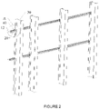
FIGURE 2 is a stereoscopic diagram hiding the screen cabinet of the present application; -
FIGURE 3 is a partial enlargement of the A part ofFIGURE 2 ; -
FIGURE 4 is an explosion view ofFIGURE 2 ; -
FIGURE 5 is a partial enlargement of the B part ofFIGURE 4 ; -
FIGURE 6 is a stereoscopic diagram of hook profile. - Reference numerals: 10, LED screen; 11, screen cabinet; 12, crossbeam; 20, hook profile; 21, mount groove; 22, bolt groove; 30, vertical column; 40, locking part.
- Hereinafter, in conjunction with the accompanying drawings and specific embodiments, the present application will be further described. It should be noted that, in the case of non-collision, a new embodiment may be formed by any combination between the embodiments described below or between the technical features.
- As described in
FIGURE 1 to FIGURE 5 , the present application discloses an installation structure for mounted LED screen which is used to installLED screen 10, comprising aLED screen 10; the LED screen comprising a screen cabinet 11 and acrossbeam 12, the screen cabinet 11 is main body part of LED screen, and thecrossbeam 12 is installation part; thecrossbeam 12 is arranged horizontally and firmly on the back of the screen cabinet 11. As described inFIGURE 6 ,hook profile 20, a side of thehook profile 20 is provided with amount groove 21 adapting to thecrossbeam 12; opening of themount groove 21 is upward, the LED screen is mounted inside themount groove 21 by thecrossbeam 12;vertical column 30,vertical column 30 is vertically arranged on the ground or other installation platform, thehook profile 20 is connected horizontally and firmly to thevertical column 30. - By the embodiment mentioned above, the
vertical column 30 is vertically arranged on the ground firstly, and thehook profile 20 is then connected horizontally and firmly to thevertical column 30, the LED screen mounted in the mount groove of thecrossbeam 12, thus leads to implement quick installation of the LED screen, which is work hour saving and convenient and quick, thus can largely improve the produce efficiency. - As a prefer embodiment, another side of the
hook profile 20 facing to thecrossbeam 12 is provided with abolt groove 22, to fix with thevertical column 30. The bolt groove is a C-typed groove, thevertical column 30 is provided with a bolt hole accordingly, thehook profile 20 and thevertical column 30 implements firm connection by bolt. At this embodiment,hook profile 20 and thevertical column 30 can be fixed quickly. Meanwhile, because the C-typed groove is a long strip structure, the builders are only demanded to put the bolt go through the C-typed groove and align the bolt hole of thevertical column 30 directly when installing, there is no need to align two or more install holes then put the bolts in. It will be time-saving and quick, and the operation is also brief and convenient. - Furthermore, there are 2
bolt grooves 22. Thehook profile 20 connects to thevertical column 30 by 2 bolts, to make the connection firmer. - As a prefer embodiment, the installation structure for mounted LED screen further comprising a
locking part 40. Thelocking part 40 is a long strip shaped C-profile steel, an opening of thelocking part 40 is firmly sleeved on a top end of thehook profile 20, an end foot reaches thecrossbeam 12, and another end foot connects to thehook profile 20 firmly. - Since the LED screen is mounted on the
hook profile 20, the gravity of the LED screen itself can make sure that it is steady at the vertical direction. While, there are plenty application the LED screen will be applied, especially the outdoor applications that will be easily affected by bad weather or other extraneous factors. If the impacts and shocks are large, theLED screen 10 will likely to get loose. Therefore, by using alocking part 40 to limit the position of theLED screen 10 at the vertical direction, the steadiness of installation will be improved. - Furthermore, the
locking part 40 implements firm connection to thehook profile 20 by bolt. As described inFIGURE 3 , similarly to thevertical column 30, thelocking part 40 also implements bolt connection by C-typed groove of thehook profile 20. This connect method is also time-saving and quick. - As a prefer embodiment, the
vertical column 30 is vertically arranged I-shaped steel. Thevertical column 30 implements firm connection with the ground or other installation platform. Furthermore, there are multiplevertical columns 30, which are arranged in line with isometric interval; thehook profile 20 is connected horizontally and firmly to thosevertical columns 30 on the side; there aremultiple hook profiles 20 as well and fix to thevertical columns 30 at different height, by which could fix more than one LED screen. - Here is a detailed illustration of the installation method for the LED screen as bellow: A step to fix a vertical column: set a
vertical column 30 on the ground or other installation platform; a step to fix a hook: using a bolt to laterally fix ahook profile 20 on thevertical column 30, to fix thehook profile 20 horizontally and firmly on thevertical column 30; a step to mount a screen: mount acrossbeam 12 of aLED screen 10 to amount groove 21 of thehook profile 20; a step to lock the screen: put the opening downward and sleeve thelocking part 40 on and top end of thehook profile 20, to make an end foot reach thecrossbeam 12, and to make another end foot connect to thehook profile 20 by bolt firmly. - By the detailed illustration of those embodiments above, it will be understood that the present application implements quick installation of
LED screen 10, and it is time-saving that only requires fewer fixing, mounting steps to accomplish, which avoids plenty of align the install holes steps that calls for plenty time and manpower. - Meanwhile, the universality of the hook profile is high and could be applied to many different
types LED screens 10, which could cut down the material cost.
Claims (8)
- An installation structure for mounted LED screens, comprising a LED screen (10) and a vertical column (30); the LED screen comprising a screen cabinet (11) and a crossbeam (12), the crossbeam is arranged horizontally and firmly on the back of the screen cabinet; the vertical column is vertically arranged on the ground or other installation platform,
characterized in thatthe installation structure for mounted LED screens further includes a hook profile (20),wherein a side of the hook profile is provided with a mount groove (21) extending in the longitudinal direction of the hook profile and adapting to the crossbeam, wherein the opening of the mount groove is upward; the crossbeam is arranged in the mount groove,wherein the hook profile is connected horizontally and firmly to the vertical column. - An installation structure for mounted LED screen of claim 1, another side of the hook profile facing to the crossbeam is provided with a bolt groove (22); the bolt groove is a C-typed groove, the vertical column is provided with a bolt hole accordingly, the hook profile and the vertical column achieve firm connection by bolt.
- An installation structure for mounted LED screen of claim 2, there are 2 bolt grooves.
- An installation structure for mounted LED screen of claim 1, the installation structure for mounted LED screen further comprising a locking part (40), the locking part is a long strip shaped C-profile steel; an opening of the locking part is firmly sleeved on a top end of the hook profile, an end foot reaches the crossbeam, and another end foot connects to the hook profile firmly.
- An installation structure for mounted LED screen of claim 4, the locking part implements firm connection to the hook profile by bolt.
- An installation structure for mounted LED screen of claim 1, the vertical column is vertically arranged I-shaped steel.
- An installation structure for mounted LED screen of claim 1, there are multiple vertical columns, which are arranged in line with isometric interval, the hook profile is connected horizontally and firmly to those vertical columns.
- An installation method for LED screen, comprising the steps as follows for setting up the installation structure for mounted LED screen according to claim 1:a step to fix the vertical column: set the vertical column (30) on the ground or other installation platform;a step to fix a hook: using a bolt to horizontally fix the hook profile (20) on the vertical column;a step to mount the screen (10): mount the horizontal crossbeam of the LED screen to the mount groove (21) extending in the longitudinal direction of the hook profile and adapting to the crossbeam so that the crossbeam is arranged in the mount groove;a step to lock the screen: put the opening downward and lock the locking part (40) firmly to the hook profile by a bolt.
Applications Claiming Priority (1)
| Application Number | Priority Date | Filing Date | Title |
|---|---|---|---|
| CN201910243811.7A CN109859645B (en) | 2019-03-28 | 2019-03-28 | A hanging type LED screen installation structure and installation method |
Publications (2)
| Publication Number | Publication Date |
|---|---|
| EP3716254A1 EP3716254A1 (en) | 2020-09-30 |
| EP3716254B1 true EP3716254B1 (en) | 2022-04-27 |
Family
ID=66668750
Family Applications (1)
| Application Number | Title | Priority Date | Filing Date |
|---|---|---|---|
| EP19176851.4A Active EP3716254B1 (en) | 2019-03-28 | 2019-05-28 | Installation structure and installation method for mounted led screen |
Country Status (2)
| Country | Link |
|---|---|
| EP (1) | EP3716254B1 (en) |
| CN (1) | CN109859645B (en) |
Families Citing this family (2)
| Publication number | Priority date | Publication date | Assignee | Title |
|---|---|---|---|---|
| CN111883007A (en) * | 2020-08-11 | 2020-11-03 | 天津奥帕斯博电子信息技术有限公司 | LED display screen lamp panel fixed knot constructs with openly maintain anti-drop function |
| NL2035497B1 (en) * | 2023-07-28 | 2025-02-11 | Vogels Ip B V | System for installing a video wall |
Family Cites Families (10)
| Publication number | Priority date | Publication date | Assignee | Title |
|---|---|---|---|---|
| JPH08152677A (en) * | 1994-11-30 | 1996-06-11 | Mitsubishi Electric Corp | Multi vision device |
| CN202056484U (en) * | 2011-05-04 | 2011-11-30 | 郑如军 | Mounting bracket of combination display screen |
| WO2013192614A2 (en) * | 2012-06-22 | 2013-12-27 | Milestone Av Technologies Llc | Panel mount with pitch, roll and yaw adjustment |
| US10121396B2 (en) * | 2016-02-02 | 2018-11-06 | Metromedia Technologies, Inc. | LED billboard system |
| KR20170100156A (en) * | 2016-02-25 | 2017-09-04 | 김대영 | Fabricated Standing Signboard |
| CN206036539U (en) * | 2016-08-26 | 2017-03-22 | 上海锐丽科技股份有限公司 | Single -upright -column concatenation screen installing support |
| CN107229178A (en) * | 2017-05-25 | 2017-10-03 | 海信集团有限公司 | Projection screen fixed mechanism |
| GB2563059A (en) * | 2017-06-02 | 2018-12-05 | Ccomm Group Ltd | A media wall |
| CN207337819U (en) * | 2017-11-08 | 2018-05-08 | 武汉元飞泓瑞科技有限公司 | Large scale liquid crystal spliced display unit |
| CN209947316U (en) * | 2019-03-28 | 2020-01-14 | 佛山市青松科技股份有限公司 | Hanging type LED screen mounting structure |
-
2019
- 2019-03-28 CN CN201910243811.7A patent/CN109859645B/en active Active
- 2019-05-28 EP EP19176851.4A patent/EP3716254B1/en active Active
Also Published As
| Publication number | Publication date |
|---|---|
| CN109859645B (en) | 2025-01-03 |
| CN109859645A (en) | 2019-06-07 |
| EP3716254A1 (en) | 2020-09-30 |
Similar Documents
| Publication | Publication Date | Title |
|---|---|---|
| KR101142898B1 (en) | Solar photovoltaic power generation module supportting structure | |
| CN202616247U (en) | Solar assembly installation support | |
| CN103280473B (en) | A kind of ballast tray formula flat-plate fastening system | |
| EP3716254A1 (en) | Installation structure and installation method for mounted led screen | |
| CN212956952U (en) | Steel construction building connecting piece | |
| CN221531347U (en) | Solar photovoltaic panel mounting structure | |
| CN211556817U (en) | Electric power tunnel support | |
| CN220693050U (en) | Assembled photovoltaic support that can install fast | |
| CN215928611U (en) | Stable form piping lane support that can install fast | |
| CN213871780U (en) | Camera support | |
| CN218990477U (en) | Assembled cantilever-shaped building base connecting frame | |
| CN217006081U (en) | Noise detection equipment convenient to multi-angle adjustment | |
| CN223867616U (en) | A type of scaffolding external steel mesh connector | |
| CN223285537U (en) | Rear-mounted cable support | |
| CN223928266U (en) | Flexible photovoltaic support and photovoltaic system | |
| CN215343770U (en) | Cable bridge convenient to maintenance is changed | |
| CN214653415U (en) | A new type of construction elevator attached to the wall frame | |
| CN217329168U (en) | Large-screen medical display connecting device | |
| CN220232641U (en) | Sign board mounting seat based on channel steel cross rod | |
| CN224212320U (en) | Tower crane attaches frame clamping device | |
| CN222773525U (en) | Anti-loosening bracket for installing refrigeration equipment | |
| CN220139158U (en) | Portable channel installation fixing device | |
| CN213501824U (en) | Integrated support of engine | |
| CN221093393U (en) | LED screen box hoisting structure | |
| CN210246248U (en) | Busway Vertical Mounting Bracket |
Legal Events
| Date | Code | Title | Description |
|---|---|---|---|
| PUAI | Public reference made under article 153(3) epc to a published international application that has entered the european phase |
Free format text: ORIGINAL CODE: 0009012 |
|
| STAA | Information on the status of an ep patent application or granted ep patent |
Free format text: STATUS: THE APPLICATION HAS BEEN PUBLISHED |
|
| AK | Designated contracting states |
Kind code of ref document: A1 Designated state(s): AL AT BE BG CH CY CZ DE DK EE ES FI FR GB GR HR HU IE IS IT LI LT LU LV MC MK MT NL NO PL PT RO RS SE SI SK SM TR |
|
| AX | Request for extension of the european patent |
Extension state: BA ME |
|
| STAA | Information on the status of an ep patent application or granted ep patent |
Free format text: STATUS: REQUEST FOR EXAMINATION WAS MADE |
|
| 17P | Request for examination filed |
Effective date: 20210326 |
|
| RBV | Designated contracting states (corrected) |
Designated state(s): AL AT BE BG CH CY CZ DE DK EE ES FI FR GB GR HR HU IE IS IT LI LT LU LV MC MK MT NL NO PL PT RO RS SE SI SK SM TR |
|
| STAA | Information on the status of an ep patent application or granted ep patent |
Free format text: STATUS: EXAMINATION IS IN PROGRESS |
|
| 17Q | First examination report despatched |
Effective date: 20210810 |
|
| REG | Reference to a national code |
Ref country code: DE Ref legal event code: R079 Ref document number: 602019014036 Country of ref document: DE Free format text: PREVIOUS MAIN CLASS: G09F0009302000 Ipc: F16M0011040000 |
|
| GRAP | Despatch of communication of intention to grant a patent |
Free format text: ORIGINAL CODE: EPIDOSNIGR1 |
|
| STAA | Information on the status of an ep patent application or granted ep patent |
Free format text: STATUS: GRANT OF PATENT IS INTENDED |
|
| RIC1 | Information provided on ipc code assigned before grant |
Ipc: F16M 11/04 20060101AFI20211028BHEP |
|
| INTG | Intention to grant announced |
Effective date: 20211130 |
|
| GRAS | Grant fee paid |
Free format text: ORIGINAL CODE: EPIDOSNIGR3 |
|
| GRAA | (expected) grant |
Free format text: ORIGINAL CODE: 0009210 |
|
| STAA | Information on the status of an ep patent application or granted ep patent |
Free format text: STATUS: THE PATENT HAS BEEN GRANTED |
|
| AK | Designated contracting states |
Kind code of ref document: B1 Designated state(s): AL AT BE BG CH CY CZ DE DK EE ES FI FR GB GR HR HU IE IS IT LI LT LU LV MC MK MT NL NO PL PT RO RS SE SI SK SM TR |
|
| REG | Reference to a national code |
Ref country code: GB Ref legal event code: FG4D |
|
| REG | Reference to a national code |
Ref country code: CH Ref legal event code: EP |
|
| REG | Reference to a national code |
Ref country code: DE Ref legal event code: R096 Ref document number: 602019014036 Country of ref document: DE |
|
| REG | Reference to a national code |
Ref country code: AT Ref legal event code: REF Ref document number: 1487173 Country of ref document: AT Kind code of ref document: T Effective date: 20220515 |
|
| REG | Reference to a national code |
Ref country code: IE Ref legal event code: FG4D |
|
| REG | Reference to a national code |
Ref country code: LT Ref legal event code: MG9D |
|
| REG | Reference to a national code |
Ref country code: NL Ref legal event code: MP Effective date: 20220427 |
|
| REG | Reference to a national code |
Ref country code: AT Ref legal event code: MK05 Ref document number: 1487173 Country of ref document: AT Kind code of ref document: T Effective date: 20220427 |
|
| PG25 | Lapsed in a contracting state [announced via postgrant information from national office to epo] |
Ref country code: NL Free format text: LAPSE BECAUSE OF FAILURE TO SUBMIT A TRANSLATION OF THE DESCRIPTION OR TO PAY THE FEE WITHIN THE PRESCRIBED TIME-LIMIT Effective date: 20220427 |
|
| PG25 | Lapsed in a contracting state [announced via postgrant information from national office to epo] |
Ref country code: SE Free format text: LAPSE BECAUSE OF FAILURE TO SUBMIT A TRANSLATION OF THE DESCRIPTION OR TO PAY THE FEE WITHIN THE PRESCRIBED TIME-LIMIT Effective date: 20220427 Ref country code: PT Free format text: LAPSE BECAUSE OF FAILURE TO SUBMIT A TRANSLATION OF THE DESCRIPTION OR TO PAY THE FEE WITHIN THE PRESCRIBED TIME-LIMIT Effective date: 20220829 Ref country code: NO Free format text: LAPSE BECAUSE OF FAILURE TO SUBMIT A TRANSLATION OF THE DESCRIPTION OR TO PAY THE FEE WITHIN THE PRESCRIBED TIME-LIMIT Effective date: 20220727 Ref country code: LT Free format text: LAPSE BECAUSE OF FAILURE TO SUBMIT A TRANSLATION OF THE DESCRIPTION OR TO PAY THE FEE WITHIN THE PRESCRIBED TIME-LIMIT Effective date: 20220427 Ref country code: HR Free format text: LAPSE BECAUSE OF FAILURE TO SUBMIT A TRANSLATION OF THE DESCRIPTION OR TO PAY THE FEE WITHIN THE PRESCRIBED TIME-LIMIT Effective date: 20220427 Ref country code: GR Free format text: LAPSE BECAUSE OF FAILURE TO SUBMIT A TRANSLATION OF THE DESCRIPTION OR TO PAY THE FEE WITHIN THE PRESCRIBED TIME-LIMIT Effective date: 20220728 Ref country code: FI Free format text: LAPSE BECAUSE OF FAILURE TO SUBMIT A TRANSLATION OF THE DESCRIPTION OR TO PAY THE FEE WITHIN THE PRESCRIBED TIME-LIMIT Effective date: 20220427 Ref country code: ES Free format text: LAPSE BECAUSE OF FAILURE TO SUBMIT A TRANSLATION OF THE DESCRIPTION OR TO PAY THE FEE WITHIN THE PRESCRIBED TIME-LIMIT Effective date: 20220427 Ref country code: BG Free format text: LAPSE BECAUSE OF FAILURE TO SUBMIT A TRANSLATION OF THE DESCRIPTION OR TO PAY THE FEE WITHIN THE PRESCRIBED TIME-LIMIT Effective date: 20220727 Ref country code: AT Free format text: LAPSE BECAUSE OF FAILURE TO SUBMIT A TRANSLATION OF THE DESCRIPTION OR TO PAY THE FEE WITHIN THE PRESCRIBED TIME-LIMIT Effective date: 20220427 |
|
| PG25 | Lapsed in a contracting state [announced via postgrant information from national office to epo] |
Ref country code: RS Free format text: LAPSE BECAUSE OF FAILURE TO SUBMIT A TRANSLATION OF THE DESCRIPTION OR TO PAY THE FEE WITHIN THE PRESCRIBED TIME-LIMIT Effective date: 20220427 Ref country code: PL Free format text: LAPSE BECAUSE OF FAILURE TO SUBMIT A TRANSLATION OF THE DESCRIPTION OR TO PAY THE FEE WITHIN THE PRESCRIBED TIME-LIMIT Effective date: 20220427 Ref country code: LV Free format text: LAPSE BECAUSE OF FAILURE TO SUBMIT A TRANSLATION OF THE DESCRIPTION OR TO PAY THE FEE WITHIN THE PRESCRIBED TIME-LIMIT Effective date: 20220427 Ref country code: IS Free format text: LAPSE BECAUSE OF FAILURE TO SUBMIT A TRANSLATION OF THE DESCRIPTION OR TO PAY THE FEE WITHIN THE PRESCRIBED TIME-LIMIT Effective date: 20220827 |
|
| REG | Reference to a national code |
Ref country code: CH Ref legal event code: PL |
|
| REG | Reference to a national code |
Ref country code: BE Ref legal event code: MM Effective date: 20220531 |
|
| REG | Reference to a national code |
Ref country code: DE Ref legal event code: R097 Ref document number: 602019014036 Country of ref document: DE |
|
| PG25 | Lapsed in a contracting state [announced via postgrant information from national office to epo] |
Ref country code: SM Free format text: LAPSE BECAUSE OF FAILURE TO SUBMIT A TRANSLATION OF THE DESCRIPTION OR TO PAY THE FEE WITHIN THE PRESCRIBED TIME-LIMIT Effective date: 20220427 Ref country code: SK Free format text: LAPSE BECAUSE OF FAILURE TO SUBMIT A TRANSLATION OF THE DESCRIPTION OR TO PAY THE FEE WITHIN THE PRESCRIBED TIME-LIMIT Effective date: 20220427 Ref country code: RO Free format text: LAPSE BECAUSE OF FAILURE TO SUBMIT A TRANSLATION OF THE DESCRIPTION OR TO PAY THE FEE WITHIN THE PRESCRIBED TIME-LIMIT Effective date: 20220427 Ref country code: MC Free format text: LAPSE BECAUSE OF FAILURE TO SUBMIT A TRANSLATION OF THE DESCRIPTION OR TO PAY THE FEE WITHIN THE PRESCRIBED TIME-LIMIT Effective date: 20220427 Ref country code: LU Free format text: LAPSE BECAUSE OF NON-PAYMENT OF DUE FEES Effective date: 20220528 Ref country code: LI Free format text: LAPSE BECAUSE OF NON-PAYMENT OF DUE FEES Effective date: 20220531 Ref country code: EE Free format text: LAPSE BECAUSE OF FAILURE TO SUBMIT A TRANSLATION OF THE DESCRIPTION OR TO PAY THE FEE WITHIN THE PRESCRIBED TIME-LIMIT Effective date: 20220427 Ref country code: DK Free format text: LAPSE BECAUSE OF FAILURE TO SUBMIT A TRANSLATION OF THE DESCRIPTION OR TO PAY THE FEE WITHIN THE PRESCRIBED TIME-LIMIT Effective date: 20220427 Ref country code: CZ Free format text: LAPSE BECAUSE OF FAILURE TO SUBMIT A TRANSLATION OF THE DESCRIPTION OR TO PAY THE FEE WITHIN THE PRESCRIBED TIME-LIMIT Effective date: 20220427 Ref country code: CH Free format text: LAPSE BECAUSE OF NON-PAYMENT OF DUE FEES Effective date: 20220531 |
|
| PLBE | No opposition filed within time limit |
Free format text: ORIGINAL CODE: 0009261 |
|
| STAA | Information on the status of an ep patent application or granted ep patent |
Free format text: STATUS: NO OPPOSITION FILED WITHIN TIME LIMIT |
|
| PG25 | Lapsed in a contracting state [announced via postgrant information from national office to epo] |
Ref country code: AL Free format text: LAPSE BECAUSE OF FAILURE TO SUBMIT A TRANSLATION OF THE DESCRIPTION OR TO PAY THE FEE WITHIN THE PRESCRIBED TIME-LIMIT Effective date: 20220427 |
|
| 26N | No opposition filed |
Effective date: 20230130 |
|
| PG25 | Lapsed in a contracting state [announced via postgrant information from national office to epo] |
Ref country code: SI Free format text: LAPSE BECAUSE OF FAILURE TO SUBMIT A TRANSLATION OF THE DESCRIPTION OR TO PAY THE FEE WITHIN THE PRESCRIBED TIME-LIMIT Effective date: 20220427 Ref country code: BE Free format text: LAPSE BECAUSE OF NON-PAYMENT OF DUE FEES Effective date: 20220531 |
|
| PG25 | Lapsed in a contracting state [announced via postgrant information from national office to epo] |
Ref country code: IT Free format text: LAPSE BECAUSE OF FAILURE TO SUBMIT A TRANSLATION OF THE DESCRIPTION OR TO PAY THE FEE WITHIN THE PRESCRIBED TIME-LIMIT Effective date: 20220427 |
|
| PG25 | Lapsed in a contracting state [announced via postgrant information from national office to epo] |
Ref country code: MK Free format text: LAPSE BECAUSE OF FAILURE TO SUBMIT A TRANSLATION OF THE DESCRIPTION OR TO PAY THE FEE WITHIN THE PRESCRIBED TIME-LIMIT Effective date: 20220427 Ref country code: CY Free format text: LAPSE BECAUSE OF FAILURE TO SUBMIT A TRANSLATION OF THE DESCRIPTION OR TO PAY THE FEE WITHIN THE PRESCRIBED TIME-LIMIT Effective date: 20220427 |
|
| PG25 | Lapsed in a contracting state [announced via postgrant information from national office to epo] |
Ref country code: HU Free format text: LAPSE BECAUSE OF FAILURE TO SUBMIT A TRANSLATION OF THE DESCRIPTION OR TO PAY THE FEE WITHIN THE PRESCRIBED TIME-LIMIT; INVALID AB INITIO Effective date: 20190528 |
|
| PG25 | Lapsed in a contracting state [announced via postgrant information from national office to epo] |
Ref country code: TR Free format text: LAPSE BECAUSE OF FAILURE TO SUBMIT A TRANSLATION OF THE DESCRIPTION OR TO PAY THE FEE WITHIN THE PRESCRIBED TIME-LIMIT Effective date: 20220427 |
|
| PG25 | Lapsed in a contracting state [announced via postgrant information from national office to epo] |
Ref country code: MT Free format text: LAPSE BECAUSE OF FAILURE TO SUBMIT A TRANSLATION OF THE DESCRIPTION OR TO PAY THE FEE WITHIN THE PRESCRIBED TIME-LIMIT Effective date: 20220427 |
|
| PG25 | Lapsed in a contracting state [announced via postgrant information from national office to epo] |
Ref country code: BG Free format text: LAPSE BECAUSE OF FAILURE TO SUBMIT A TRANSLATION OF THE DESCRIPTION OR TO PAY THE FEE WITHIN THE PRESCRIBED TIME-LIMIT Effective date: 20220427 |
|
| PG25 | Lapsed in a contracting state [announced via postgrant information from national office to epo] |
Ref country code: BG Free format text: LAPSE BECAUSE OF FAILURE TO SUBMIT A TRANSLATION OF THE DESCRIPTION OR TO PAY THE FEE WITHIN THE PRESCRIBED TIME-LIMIT Effective date: 20220427 |
|
| PGFP | Annual fee paid to national office [announced via postgrant information from national office to epo] |
Ref country code: DE Payment date: 20250401 Year of fee payment: 7 |
|
| PGFP | Annual fee paid to national office [announced via postgrant information from national office to epo] |
Ref country code: GB Payment date: 20260330 Year of fee payment: 8 |
|
| PGFP | Annual fee paid to national office [announced via postgrant information from national office to epo] |
Ref country code: IE Payment date: 20260330 Year of fee payment: 8 |
|
| PGFP | Annual fee paid to national office [announced via postgrant information from national office to epo] |
Ref country code: FR Payment date: 20260326 Year of fee payment: 8 |