EP3715928B1 - Cable with semi-conducting outermost layer - Google Patents
Cable with semi-conducting outermost layer Download PDFInfo
- Publication number
- EP3715928B1 EP3715928B1 EP20162931.8A EP20162931A EP3715928B1 EP 3715928 B1 EP3715928 B1 EP 3715928B1 EP 20162931 A EP20162931 A EP 20162931A EP 3715928 B1 EP3715928 B1 EP 3715928B1
- Authority
- EP
- European Patent Office
- Prior art keywords
- cable
- conductive layer
- semi
- jacket
- external semi
- Prior art date
- Legal status (The legal status is an assumption and is not a legal conclusion. Google has not performed a legal analysis and makes no representation as to the accuracy of the status listed.)
- Active
Links
- 239000010410 layer Substances 0.000 claims description 131
- OKTJSMMVPCPJKN-UHFFFAOYSA-N Carbon Chemical compound [C] OKTJSMMVPCPJKN-UHFFFAOYSA-N 0.000 claims description 22
- 239000002861 polymer material Substances 0.000 claims description 22
- 229920005601 base polymer Polymers 0.000 claims description 21
- 230000003287 optical effect Effects 0.000 claims description 20
- 239000002041 carbon nanotube Substances 0.000 claims description 17
- 229910021393 carbon nanotube Inorganic materials 0.000 claims description 17
- 239000011231 conductive filler Substances 0.000 claims description 17
- 239000000203 mixture Substances 0.000 claims description 15
- 239000003086 colorant Substances 0.000 claims description 13
- -1 polyethylene, ethylene propylene Polymers 0.000 claims description 13
- 239000013047 polymeric layer Substances 0.000 claims description 10
- 239000004800 polyvinyl chloride Substances 0.000 claims description 6
- 239000000654 additive Substances 0.000 claims description 5
- 239000000945 filler Substances 0.000 claims description 5
- 229920000915 polyvinyl chloride Polymers 0.000 claims description 4
- RNFJDJUURJAICM-UHFFFAOYSA-N 2,2,4,4,6,6-hexaphenoxy-1,3,5-triaza-2$l^{5},4$l^{5},6$l^{5}-triphosphacyclohexa-1,3,5-triene Chemical class N=1P(OC=2C=CC=CC=2)(OC=2C=CC=CC=2)=NP(OC=2C=CC=CC=2)(OC=2C=CC=CC=2)=NP=1(OC=1C=CC=CC=1)OC1=CC=CC=C1 RNFJDJUURJAICM-UHFFFAOYSA-N 0.000 claims description 3
- 239000005038 ethylene vinyl acetate Substances 0.000 claims description 3
- DQXBYHZEEUGOBF-UHFFFAOYSA-N but-3-enoic acid;ethene Chemical compound C=C.OC(=O)CC=C DQXBYHZEEUGOBF-UHFFFAOYSA-N 0.000 claims description 2
- 229920001200 poly(ethylene-vinyl acetate) Polymers 0.000 claims description 2
- 229920001971 elastomer Polymers 0.000 claims 1
- 239000000463 material Substances 0.000 description 20
- 238000012360 testing method Methods 0.000 description 18
- 239000004020 conductor Substances 0.000 description 15
- 239000004698 Polyethylene Substances 0.000 description 12
- 229920000573 polyethylene Polymers 0.000 description 12
- XLYOFNOQVPJJNP-UHFFFAOYSA-N water Substances O XLYOFNOQVPJJNP-UHFFFAOYSA-N 0.000 description 10
- 229910052751 metal Inorganic materials 0.000 description 8
- 239000002184 metal Substances 0.000 description 7
- VGGSQFUCUMXWEO-UHFFFAOYSA-N Ethene Chemical compound C=C VGGSQFUCUMXWEO-UHFFFAOYSA-N 0.000 description 6
- 239000005977 Ethylene Substances 0.000 description 6
- 229920001577 copolymer Polymers 0.000 description 6
- 229920001903 high density polyethylene Polymers 0.000 description 6
- 239000004700 high-density polyethylene Substances 0.000 description 6
- 239000006229 carbon black Substances 0.000 description 5
- 239000011521 glass Substances 0.000 description 5
- 239000010439 graphite Substances 0.000 description 5
- 229910002804 graphite Inorganic materials 0.000 description 5
- 238000000034 method Methods 0.000 description 5
- 229920000181 Ethylene propylene rubber Polymers 0.000 description 4
- 238000004040 coloring Methods 0.000 description 4
- 229920001684 low density polyethylene Polymers 0.000 description 4
- 239000004702 low-density polyethylene Substances 0.000 description 4
- 229920001179 medium density polyethylene Polymers 0.000 description 4
- 239000004701 medium-density polyethylene Substances 0.000 description 4
- 239000013307 optical fiber Substances 0.000 description 4
- RYGMFSIKBFXOCR-UHFFFAOYSA-N Copper Chemical compound [Cu] RYGMFSIKBFXOCR-UHFFFAOYSA-N 0.000 description 3
- 229910000831 Steel Inorganic materials 0.000 description 3
- 229910052782 aluminium Inorganic materials 0.000 description 3
- XAGFODPZIPBFFR-UHFFFAOYSA-N aluminium Chemical compound [Al] XAGFODPZIPBFFR-UHFFFAOYSA-N 0.000 description 3
- 230000005540 biological transmission Effects 0.000 description 3
- 238000000576 coating method Methods 0.000 description 3
- 229920001940 conductive polymer Polymers 0.000 description 3
- 229910052802 copper Inorganic materials 0.000 description 3
- 239000010949 copper Substances 0.000 description 3
- 230000007547 defect Effects 0.000 description 3
- 238000009826 distribution Methods 0.000 description 3
- 238000001125 extrusion Methods 0.000 description 3
- 229920000642 polymer Polymers 0.000 description 3
- 239000010959 steel Substances 0.000 description 3
- 229920002943 EPDM rubber Polymers 0.000 description 2
- BAPJBEWLBFYGME-UHFFFAOYSA-N Methyl acrylate Chemical compound COC(=O)C=C BAPJBEWLBFYGME-UHFFFAOYSA-N 0.000 description 2
- 239000004743 Polypropylene Substances 0.000 description 2
- 206010063493 Premature ageing Diseases 0.000 description 2
- GWEVSGVZZGPLCZ-UHFFFAOYSA-N Titan oxide Chemical compound O=[Ti]=O GWEVSGVZZGPLCZ-UHFFFAOYSA-N 0.000 description 2
- 150000001336 alkenes Chemical class 0.000 description 2
- 239000004760 aramid Substances 0.000 description 2
- 229920003235 aromatic polyamide Polymers 0.000 description 2
- 230000004888 barrier function Effects 0.000 description 2
- 238000005253 cladding Methods 0.000 description 2
- 239000011248 coating agent Substances 0.000 description 2
- 230000007797 corrosion Effects 0.000 description 2
- 238000005260 corrosion Methods 0.000 description 2
- 238000010292 electrical insulation Methods 0.000 description 2
- CGPRUXZTHGTMKW-UHFFFAOYSA-N ethene;ethyl prop-2-enoate Chemical compound C=C.CCOC(=O)C=C CGPRUXZTHGTMKW-UHFFFAOYSA-N 0.000 description 2
- 229920001519 homopolymer Polymers 0.000 description 2
- 238000009434 installation Methods 0.000 description 2
- 238000004519 manufacturing process Methods 0.000 description 2
- 230000007935 neutral effect Effects 0.000 description 2
- 230000035515 penetration Effects 0.000 description 2
- 229920000728 polyester Polymers 0.000 description 2
- 229920000570 polyether Polymers 0.000 description 2
- 229920001155 polypropylene Polymers 0.000 description 2
- 229910000838 Al alloy Inorganic materials 0.000 description 1
- 229920000089 Cyclic olefin copolymer Polymers 0.000 description 1
- 244000043261 Hevea brasiliensis Species 0.000 description 1
- 229920010126 Linear Low Density Polyethylene (LLDPE) Polymers 0.000 description 1
- 239000004721 Polyphenylene oxide Substances 0.000 description 1
- 208000013201 Stress fracture Diseases 0.000 description 1
- XTXRWKRVRITETP-UHFFFAOYSA-N Vinyl acetate Chemical compound CC(=O)OC=C XTXRWKRVRITETP-UHFFFAOYSA-N 0.000 description 1
- 208000027418 Wounds and injury Diseases 0.000 description 1
- 230000000996 additive effect Effects 0.000 description 1
- HSFWRNGVRCDJHI-UHFFFAOYSA-N alpha-acetylene Natural products C#C HSFWRNGVRCDJHI-UHFFFAOYSA-N 0.000 description 1
- CQEYYJKEWSMYFG-UHFFFAOYSA-N butyl acrylate Chemical compound CCCCOC(=O)C=C CQEYYJKEWSMYFG-UHFFFAOYSA-N 0.000 description 1
- 229920005549 butyl rubber Polymers 0.000 description 1
- 230000015556 catabolic process Effects 0.000 description 1
- 229940125782 compound 2 Drugs 0.000 description 1
- 150000001875 compounds Chemical class 0.000 description 1
- 239000012141 concentrate Substances 0.000 description 1
- 238000005520 cutting process Methods 0.000 description 1
- 230000007423 decrease Effects 0.000 description 1
- 230000006735 deficit Effects 0.000 description 1
- 238000006731 degradation reaction Methods 0.000 description 1
- 230000005684 electric field Effects 0.000 description 1
- 239000012777 electrically insulating material Substances 0.000 description 1
- 230000007613 environmental effect Effects 0.000 description 1
- 229920001038 ethylene copolymer Polymers 0.000 description 1
- 230000009970 fire resistant effect Effects 0.000 description 1
- 239000003063 flame retardant Substances 0.000 description 1
- 229910052736 halogen Inorganic materials 0.000 description 1
- 150000002367 halogens Chemical class 0.000 description 1
- 238000009413 insulation Methods 0.000 description 1
- 239000011133 lead Substances 0.000 description 1
- VTHJTEIRLNZDEV-UHFFFAOYSA-L magnesium dihydroxide Chemical compound [OH-].[OH-].[Mg+2] VTHJTEIRLNZDEV-UHFFFAOYSA-L 0.000 description 1
- 229910001862 magnesium hydroxide Inorganic materials 0.000 description 1
- 239000000347 magnesium hydroxide Substances 0.000 description 1
- 238000012423 maintenance Methods 0.000 description 1
- 239000010445 mica Substances 0.000 description 1
- 229910052618 mica group Inorganic materials 0.000 description 1
- 229920003052 natural elastomer Polymers 0.000 description 1
- 229920001194 natural rubber Polymers 0.000 description 1
- JRZJOMJEPLMPRA-UHFFFAOYSA-N olefin Natural products CCCCCCCC=C JRZJOMJEPLMPRA-UHFFFAOYSA-N 0.000 description 1
- 229920001197 polyacetylene Polymers 0.000 description 1
- 229920000767 polyaniline Polymers 0.000 description 1
- 229920002959 polymer blend Polymers 0.000 description 1
- 229920000098 polyolefin Polymers 0.000 description 1
- 229920000128 polypyrrole Polymers 0.000 description 1
- QQONPFPTGQHPMA-UHFFFAOYSA-N propylene Natural products CC=C QQONPFPTGQHPMA-UHFFFAOYSA-N 0.000 description 1
- 125000004805 propylene group Chemical group [H]C([H])([H])C([H])([*:1])C([H])([H])[*:2] 0.000 description 1
- 239000000779 smoke Substances 0.000 description 1
- 229920001169 thermoplastic Polymers 0.000 description 1
- 239000004416 thermosoftening plastic Substances 0.000 description 1
- 239000004408 titanium dioxide Substances 0.000 description 1
Images

Classifications
-
- H—ELECTRICITY
- H01—ELECTRIC ELEMENTS
- H01B—CABLES; CONDUCTORS; INSULATORS; SELECTION OF MATERIALS FOR THEIR CONDUCTIVE, INSULATING OR DIELECTRIC PROPERTIES
- H01B1/00—Conductors or conductive bodies characterised by the conductive materials; Selection of materials as conductors
- H01B1/14—Conductive material dispersed in non-conductive inorganic material
- H01B1/18—Conductive material dispersed in non-conductive inorganic material the conductive material comprising carbon-silicon compounds, carbon or silicon
-
- H—ELECTRICITY
- H01—ELECTRIC ELEMENTS
- H01B—CABLES; CONDUCTORS; INSULATORS; SELECTION OF MATERIALS FOR THEIR CONDUCTIVE, INSULATING OR DIELECTRIC PROPERTIES
- H01B7/00—Insulated conductors or cables characterised by their form
- H01B7/02—Disposition of insulation
- H01B7/0208—Cables with several layers of insulating material
- H01B7/0225—Three or more layers
-
- H—ELECTRICITY
- H01—ELECTRIC ELEMENTS
- H01B—CABLES; CONDUCTORS; INSULATORS; SELECTION OF MATERIALS FOR THEIR CONDUCTIVE, INSULATING OR DIELECTRIC PROPERTIES
- H01B7/00—Insulated conductors or cables characterised by their form
- H01B7/36—Insulated conductors or cables characterised by their form with distinguishing or length marks
- H01B7/361—Insulated conductors or cables characterised by their form with distinguishing or length marks being the colour of the insulation or conductor
-
- G—PHYSICS
- G02—OPTICS
- G02B—OPTICAL ELEMENTS, SYSTEMS OR APPARATUS
- G02B6/00—Light guides; Structural details of arrangements comprising light guides and other optical elements, e.g. couplings
- G02B6/44—Mechanical structures for providing tensile strength and external protection for fibres, e.g. optical transmission cables
- G02B6/4401—Optical cables
- G02B6/4415—Cables for special applications
-
- C—CHEMISTRY; METALLURGY
- C08—ORGANIC MACROMOLECULAR COMPOUNDS; THEIR PREPARATION OR CHEMICAL WORKING-UP; COMPOSITIONS BASED THEREON
- C08K—Use of inorganic or non-macromolecular organic substances as compounding ingredients
- C08K3/00—Use of inorganic substances as compounding ingredients
- C08K3/02—Elements
- C08K3/04—Carbon
- C08K3/041—Carbon nanotubes
-
- C—CHEMISTRY; METALLURGY
- C08—ORGANIC MACROMOLECULAR COMPOUNDS; THEIR PREPARATION OR CHEMICAL WORKING-UP; COMPOSITIONS BASED THEREON
- C08K—Use of inorganic or non-macromolecular organic substances as compounding ingredients
- C08K5/00—Use of organic ingredients
- C08K5/0008—Organic ingredients according to more than one of the "one dot" groups of C08K5/01 - C08K5/59
- C08K5/0041—Optical brightening agents, organic pigments
-
- G—PHYSICS
- G02—OPTICS
- G02B—OPTICAL ELEMENTS, SYSTEMS OR APPARATUS
- G02B6/00—Light guides; Structural details of arrangements comprising light guides and other optical elements, e.g. couplings
- G02B6/44—Mechanical structures for providing tensile strength and external protection for fibres, e.g. optical transmission cables
- G02B6/4401—Optical cables
- G02B6/4415—Cables for special applications
- G02B6/4416—Heterogeneous cables
-
- G—PHYSICS
- G02—OPTICS
- G02B—OPTICAL ELEMENTS, SYSTEMS OR APPARATUS
- G02B6/00—Light guides; Structural details of arrangements comprising light guides and other optical elements, e.g. couplings
- G02B6/46—Processes or apparatus adapted for installing or repairing optical fibres or optical cables
- G02B6/56—Processes for repairing optical cables
- G02B6/562—Processes for repairing optical cables locatable, e.g. using magnetic means
-
- H—ELECTRICITY
- H01—ELECTRIC ELEMENTS
- H01B—CABLES; CONDUCTORS; INSULATORS; SELECTION OF MATERIALS FOR THEIR CONDUCTIVE, INSULATING OR DIELECTRIC PROPERTIES
- H01B1/00—Conductors or conductive bodies characterised by the conductive materials; Selection of materials as conductors
- H01B1/20—Conductive material dispersed in non-conductive organic material
- H01B1/24—Conductive material dispersed in non-conductive organic material the conductive material comprising carbon-silicon compounds, carbon or silicon
-
- H—ELECTRICITY
- H01—ELECTRIC ELEMENTS
- H01B—CABLES; CONDUCTORS; INSULATORS; SELECTION OF MATERIALS FOR THEIR CONDUCTIVE, INSULATING OR DIELECTRIC PROPERTIES
- H01B7/00—Insulated conductors or cables characterised by their form
- H01B7/17—Protection against damage caused by external factors, e.g. sheaths or armouring
- H01B7/18—Protection against damage caused by wear, mechanical force or pressure; Sheaths; Armouring
- H01B7/1875—Multi-layer sheaths
-
- H—ELECTRICITY
- H01—ELECTRIC ELEMENTS
- H01B—CABLES; CONDUCTORS; INSULATORS; SELECTION OF MATERIALS FOR THEIR CONDUCTIVE, INSULATING OR DIELECTRIC PROPERTIES
- H01B7/00—Insulated conductors or cables characterised by their form
- H01B7/17—Protection against damage caused by external factors, e.g. sheaths or armouring
- H01B7/28—Protection against damage caused by moisture, corrosion, chemical attack or weather
- H01B7/282—Preventing penetration of fluid, e.g. water or humidity, into conductor or cable
- H01B7/285—Preventing penetration of fluid, e.g. water or humidity, into conductor or cable by completely or partially filling interstices in the cable
-
- H—ELECTRICITY
- H01—ELECTRIC ELEMENTS
- H01B—CABLES; CONDUCTORS; INSULATORS; SELECTION OF MATERIALS FOR THEIR CONDUCTIVE, INSULATING OR DIELECTRIC PROPERTIES
- H01B7/00—Insulated conductors or cables characterised by their form
- H01B7/17—Protection against damage caused by external factors, e.g. sheaths or armouring
- H01B7/29—Protection against damage caused by extremes of temperature or by flame
- H01B7/295—Protection against damage caused by extremes of temperature or by flame using material resistant to flame
-
- H—ELECTRICITY
- H01—ELECTRIC ELEMENTS
- H01B—CABLES; CONDUCTORS; INSULATORS; SELECTION OF MATERIALS FOR THEIR CONDUCTIVE, INSULATING OR DIELECTRIC PROPERTIES
- H01B9/00—Power cables
- H01B9/02—Power cables with screens or conductive layers, e.g. for avoiding large potential gradients
-
- H—ELECTRICITY
- H01—ELECTRIC ELEMENTS
- H01B—CABLES; CONDUCTORS; INSULATORS; SELECTION OF MATERIALS FOR THEIR CONDUCTIVE, INSULATING OR DIELECTRIC PROPERTIES
- H01B9/00—Power cables
- H01B9/02—Power cables with screens or conductive layers, e.g. for avoiding large potential gradients
- H01B9/027—Power cables with screens or conductive layers, e.g. for avoiding large potential gradients composed of semi-conducting layers
-
- C—CHEMISTRY; METALLURGY
- C08—ORGANIC MACROMOLECULAR COMPOUNDS; THEIR PREPARATION OR CHEMICAL WORKING-UP; COMPOSITIONS BASED THEREON
- C08K—Use of inorganic or non-macromolecular organic substances as compounding ingredients
- C08K3/00—Use of inorganic substances as compounding ingredients
- C08K3/18—Oxygen-containing compounds, e.g. metal carbonyls
- C08K3/20—Oxides; Hydroxides
- C08K3/22—Oxides; Hydroxides of metals
- C08K2003/2237—Oxides; Hydroxides of metals of titanium
- C08K2003/2241—Titanium dioxide
-
- C—CHEMISTRY; METALLURGY
- C08—ORGANIC MACROMOLECULAR COMPOUNDS; THEIR PREPARATION OR CHEMICAL WORKING-UP; COMPOSITIONS BASED THEREON
- C08K—Use of inorganic or non-macromolecular organic substances as compounding ingredients
- C08K3/00—Use of inorganic substances as compounding ingredients
- C08K3/01—Use of inorganic substances as compounding ingredients characterized by their specific function
- C08K3/014—Stabilisers against oxidation, heat, light or ozone
-
- C—CHEMISTRY; METALLURGY
- C08—ORGANIC MACROMOLECULAR COMPOUNDS; THEIR PREPARATION OR CHEMICAL WORKING-UP; COMPOSITIONS BASED THEREON
- C08K—Use of inorganic or non-macromolecular organic substances as compounding ingredients
- C08K3/00—Use of inorganic substances as compounding ingredients
- C08K3/01—Use of inorganic substances as compounding ingredients characterized by their specific function
- C08K3/016—Flame-proofing or flame-retarding additives
-
- G—PHYSICS
- G01—MEASURING; TESTING
- G01R—MEASURING ELECTRIC VARIABLES; MEASURING MAGNETIC VARIABLES
- G01R31/00—Arrangements for testing electric properties; Arrangements for locating electric faults; Arrangements for electrical testing characterised by what is being tested not provided for elsewhere
- G01R31/12—Testing dielectric strength or breakdown voltage ; Testing or monitoring effectiveness or level of insulation, e.g. of a cable or of an apparatus, for example using partial discharge measurements; Electrostatic testing
- G01R31/1227—Testing dielectric strength or breakdown voltage ; Testing or monitoring effectiveness or level of insulation, e.g. of a cable or of an apparatus, for example using partial discharge measurements; Electrostatic testing of components, parts or materials
- G01R31/1263—Testing dielectric strength or breakdown voltage ; Testing or monitoring effectiveness or level of insulation, e.g. of a cable or of an apparatus, for example using partial discharge measurements; Electrostatic testing of components, parts or materials of solid or fluid materials, e.g. insulation films, bulk material; of semiconductors or LV electronic components or parts; of cable, line or wire insulation
- G01R31/1272—Testing dielectric strength or breakdown voltage ; Testing or monitoring effectiveness or level of insulation, e.g. of a cable or of an apparatus, for example using partial discharge measurements; Electrostatic testing of components, parts or materials of solid or fluid materials, e.g. insulation films, bulk material; of semiconductors or LV electronic components or parts; of cable, line or wire insulation of cable, line or wire insulation, e.g. using partial discharge measurements
-
- G—PHYSICS
- G02—OPTICS
- G02B—OPTICAL ELEMENTS, SYSTEMS OR APPARATUS
- G02B6/00—Light guides; Structural details of arrangements comprising light guides and other optical elements, e.g. couplings
- G02B6/44—Mechanical structures for providing tensile strength and external protection for fibres, e.g. optical transmission cables
- G02B6/4401—Optical cables
- G02B6/4429—Means specially adapted for strengthening or protecting the cables
-
- G—PHYSICS
- G02—OPTICS
- G02B—OPTICAL ELEMENTS, SYSTEMS OR APPARATUS
- G02B6/00—Light guides; Structural details of arrangements comprising light guides and other optical elements, e.g. couplings
- G02B6/44—Mechanical structures for providing tensile strength and external protection for fibres, e.g. optical transmission cables
- G02B6/4479—Manufacturing methods of optical cables
- G02B6/4482—Code or colour marking
-
- H—ELECTRICITY
- H01—ELECTRIC ELEMENTS
- H01B—CABLES; CONDUCTORS; INSULATORS; SELECTION OF MATERIALS FOR THEIR CONDUCTIVE, INSULATING OR DIELECTRIC PROPERTIES
- H01B11/00—Communication cables or conductors
- H01B11/22—Cables including at least one electrical conductor together with optical fibres
-
- H—ELECTRICITY
- H01—ELECTRIC ELEMENTS
- H01B—CABLES; CONDUCTORS; INSULATORS; SELECTION OF MATERIALS FOR THEIR CONDUCTIVE, INSULATING OR DIELECTRIC PROPERTIES
- H01B7/00—Insulated conductors or cables characterised by their form
- H01B7/17—Protection against damage caused by external factors, e.g. sheaths or armouring
- H01B7/28—Protection against damage caused by moisture, corrosion, chemical attack or weather
- H01B7/282—Preventing penetration of fluid, e.g. water or humidity, into conductor or cable
-
- H—ELECTRICITY
- H01—ELECTRIC ELEMENTS
- H01B—CABLES; CONDUCTORS; INSULATORS; SELECTION OF MATERIALS FOR THEIR CONDUCTIVE, INSULATING OR DIELECTRIC PROPERTIES
- H01B9/00—Power cables
- H01B9/005—Power cables including optical transmission elements
Definitions
- the present disclosure relates to a cable, such as an electrical cable or
- electrical cables for power transmission or distribution may vary according to the intended applications.
- electrical cables may be categorized as low voltage (LV), medium voltage (MV), or high voltage (HV).
- low voltage is used to indicate a voltage up to 1 kV
- medium voltage is used to indicate a voltage of from 5 kV to 46 kV
- high voltage is used to indicate a voltage greater than 46 kV.
- the cable generally comprises a transmissive core and a jacket having at least an outermost polymeric layer.
- the transmissive core is an insulated core comprising, from interior to exterior, at least one electrical electrically conductive element, an electrical insulation system, and a metallic screen. Additional layers may also be present.
- the electrical insulation system generally comprises an inner semi-conductive layer, an electrically insulating layer and an outer semi-conductive layer.
- the transmissive core comprises at least one optical waveguide
- the cable comprises a plurality of protecting layers under the jacket and surrounding the transmissive core.
- WO 2017/084709 discloses an electric power cable.
- US 2010/0078194 discloses a medium or high voltage cable comprising a conductive core, an inner semiconductive layer, an insulating layer, an outer semiconductive layer, neutral conductors and a jacket, in which at least one of the inner semiconductive layer, the outer semiconductive layer and the jacket comprises a carbon nanotube composition.
- KR 2016 0121873 discloses an electrical cable with an external semi-conductive layer comprising a conductive filler in an amount between 20% and 40% by weight.
- Jacket integrity tests are important because any defect in and/or damage to the jacket of the cable constitutes a discontinuity in the polymeric layer, which can ultimately cause electrical failure as the transmissive cores are no longer protected by the jacket as originally designed.
- the presence of a cut in the jacket of the cable represents a preferential route for the entry of water or moisture to the interior (i.e. towards the core) of the cable, which can cause significant problems including short circuit and corrosion of the metal conductors.
- one jacket integrity test is known as the DC withstand test and may be conducted according to methods known in the art, such as the ICEA (Insulated Cable Engineers Association, Inc.) Standard S-108-720-2004 for Extruded Insulation Power Cables Rated Above 46 Through 345 kV (Section E5.2), 2004.
- ICEA Insulated Cable Engineers Association, Inc.
- S-108-720-2004 Extruded Insulation Power Cables Rated Above 46 Through 345 kV (Section E5.2), 2004.
- a semi-conductive layer that may be made either of graphite or of an extruded semi-conductive compound
- the second electrode is represented by the metal component arranged in a radially internal position relative to the jacket to be tested, such as the metal screen.
- a DC voltage of about 150 V/mil (6kV/mm) and up to a maximum of 24kV is applied between the metallic screen and the applied semi-conductive layer.
- the jacket has a defect and/or damage such as to create an electrically conductive path in the thickness of the jacket between the electrodes in the test, a short-circuit condition will exist and an overcurrent will be produced.
- the establishment of the overcurrent condition thus enables a person skilled in the art to confirm the presence of damage to and/or a defect in the jacket of the cable.
- the DC withstand test of the jacket is performed directly at the production plant after the process for producing the cable. Sometimes, the DC withstand test is also repeated once the cable has been installed, so as to check for any evidence of damage produced in the outer jacket due to the laying operations of the cable. Repeating the testing once the cable has been installed can be highly desirable, especially in the case of underground installations in which the cable is placed directly in the ground without the aid of conduits to contain it.
- Graphite has traditionally been used for the outer semi-conductive layer because it can be easily removed at one end of the cable, as required for conducting the DC withstand test.
- graphite may offer problems during maintenance testing because the graphite is messy and it may have rubbed off during installation.
- a thin layer of semi-conductive polymeric material may alternatively be extruded over the jacket.
- the jacket and the outer semi-conductive layer are both generally black and, thus hardly distinguishable.
- the jacket is usually black to aid with sunlight resistance.
- the semi-conductive layer is usually black, as a common and cheap way for making a semi-conductive layer is to add carbon black (defeating any other colorants) to a polyethylene material.
- US 9 064 618 discloses an electrical cable having a semi-conductive material extruded around and in contact with an outermost layer of a cable jacket.
- the semi-conductive layer can be of a color other than black and may be at least a material selected from the group of conductive polymers consisting essentially of polyaniline, polypyrrole and polyacetylene, which are per se conductive materials.
- a jacket integrity test can also be applied to optical cables.
- Optical cables can equally suffer performance decline or impairment in case of damage to the outer jacket, for example because of water penetration.
- Optical cables can be successfully tested by, for example, the above-mentioned jacket integrity standard when they comprise at least one metallic element in a radially internal position with respect to the outer jacket, such as armour, strength elements or tube housing optical waveguides.
- the electrically conductive polymers proposed by US 9 064 618 can be disadvantageous in terms of costs (they are generally more expensive with respect to a non-conductive polyethylene polymer loaded with carbon black) and in terms of compatibility with the base polymer material typically used for the jacket (e.g. low density polyethylene (LDPE), medium density polyethylene (MDPE), high density polyethylene (HDPE), polyvinyl chloride (PVC)).
- LDPE low density polyethylene
- MDPE medium density polyethylene
- HDPE high density polyethylene
- PVC polyvinyl chloride
- the compatibility of the materials of the jacket and the external semi-conductive layer is important, for example, to attain a suitable adhesion during the extrusion process of the semi-conductive layer over the jacket.
- an object of the present disclosure is that of providing a cable with an external semi-conductive layer, which has reduced cost and improved compatibility of the materials of the jacket and the external semi-conductive layer, and that enables the provision of an external semi-conductive layer of the color requested by the standard and/or by the customer.
- the Applicant also observes that, in general, it is useful that the different elements of a cable are visually distinguishable from each other.
- an ancillary object of the present disclosure is that of providing a cable with an external semi-conductive layer visually distinguishable from the jacket, even when the latter is black. Accordingly, in a first aspect the present disclosure relates to a cable according to claim 1.
- the cable of the present disclosure is an electrical cable for power transmission or distribution and the transmissive core is an insulated core comprising an electrically conductive element surrounded by an electrical insulating system and a metallic screen.
- the electrical insulating system comprises an inner semi-conductive layer, an insulating layer and an outer semi-conductive layer.
- the cable of the present disclosure is an optical cable for telecommunication
- the transmissive core comprises at least one optical waveguide
- the cable comprises a plurality of protecting layers under the jacket and surrounding the transmissive core, of which at least one is metallic.
- protecting layers are polymeric coating, buffer, polymeric or metal tube, water-blocking filler, metallic water barrier, flame retardant polymeric layer, fire-resistant glass or mica layers, metal armour in form of wires or optionally corrugated sheath.
- the optical waveguide comprises a glass core and a glass cladding.
- a base polymer material made, for example, of an ethylene homopolymer, ethylene copolymer or PVC enables to obtain a cable which has reduced cost (thanks to the fact that such a base polymer material is cheaper with respect to the electrically conductive polymers used by US 9 064 618 ) and improves the affinity between outer jacket and external semi-conductive layer, as the base polymer material of the latter is the same or similar or anyway chemically compatible with the base polymer material typically used in the art to make the jacket.
- the carbon nanotubes as electrically conductive filler can be used in a minimal percentage that, on the one side, is sufficient to provide the base polymer material of the external semi-conductive layer with the required electrical conductivity for integrity tests and, on the other side, does not affect the natural color thereof.
- the base polymer material of the external semi-conductive layer of the present disclosure can be made suitably conductive while keeping its natural color which, in the case of polyethylene material, is substantially transparent.
- the external semi-conductive layer colored, by adding a colorant to the base polymer material.
- the expression "transparent" in connection with a material of a cable layer is used to indicate that the material enables one to see through it, in particular to see the color of the underlying layer through it.
- the electrically conductive filler comprises carbon nanotubes in an amount of at least 0.05wt% with respect to the total weight of the semi-conductive layer composition.
- the electrically conductive filler comprises carbon nanotubes in an amount of 0.5wt% at most.
- this amount of carbon nanotubes can be sufficiently high to provide a semi-conductive layer with the electrical conductivity required, for example, to perform an integrity test, and at the same time could maintain the natural appearance or coloring of the base polymer material visually perceivable.
- an amount of 20-25wt%, with respect to the weight of the semi-conductive composition is required. Such an amount completely changes the natural appearance or the coloring of the base polymer material of a semi-conductive layer by blackening it.
- the external semi-conductive layer of the present cable has an electrical conductivity of at least 10 -2 S/cm (corresponding to a resistivity of 1 ⁇ ⁇ m) as measured, for example, according IEC 60093, 2 nd ed, 1980 (volume resistivity).
- the external semi-conductive layer of the present cable can have an electrical conductivity of 10 -1 S/cm (corresponding to resistivity of 10 -1 ⁇ ⁇ m) at most.
- the electrically conductive filler consists of carbon nanotubes only.
- the electrically conductive filler of the present disclosure is devoid of carbon black. This to avoid altering, and in particular, blackening, the natural appearance or the coloring of the base polymer material of the semi-conductive layer.
- the electrically conductive filler comprises an amount of carbon nanotubes suitable to provide a conductivity of at least 10 -2 S/cm (corresponding to a resistivity of 1 ⁇ ⁇ m).
- the electrically conductive filler comprises an amount of carbon nanotubes adapted to achieve a conductivity of 10 -1 S/cm (corresponding to resistivity of 10 -1 ⁇ ⁇ m) at most.
- the Applicant observed that the above values of conductivity are suitable to perform a jacket integrity test wherein a DC voltage of about 150 V/mil (6kV/mm) and up to a maximum of 24kV is applied between the metallic screen and the external semi-conductive layer to verify the integrity of the jacket.
- a thickness of the semi-conductive layer is up to 20% of a combined thickness of the jacket and the semi-conductive layer.
- the external semi-conductive layer of the cable is different in color from the outermost polymeric layer of the jacket, thus visually distinguishable therefrom.
- the external semi-conductive layer can have the appearance of the natural base polymer material (substantially transparent in the case of polyethylene, white in the case of PVC or in case of polyethylene charged with a filler), while the jacket can be black (to aid with sunlight resistance) or of any other color (e.g. to meet customer and/or law requirements, like in the case of MV cables).
- the external semi-conductive layer can be colored while the jacket can be left uncolored (as hidden from the sunlight) or colored in a different color.
- the external semi-conductive layer is of a color other than black.
- the external semi-conductive layer also comprises a colorant.
- a colorant the above cited amount of carbon nanotubes is sufficiently low to guarantee that the color imparted to the base polymer material by the colorant is maintained and not blackened by the electrically conductive filler.
- the external semi-conductive layer comprises the colorant in an amount of at least 0.01 wt%, with respect to the total weight of the semi-conductive layer composition.
- the external semi-conductive layer comprises the colorant in an amount of 2.5 wt% at most, for example of from 0.015 wt% to 1.2 wt%, with respect to the total weight of the semi-conductive layer composition.
- Colorants suitable for the polymeric material of the external semi-conductive layer can be readily selected by the skilled person. See, for example, Fundamentals of Color and Additives, Utilization of Color & Additive Concentrates, Clariant International Ltd, 2013.
- the jacket underlying the external semi-conductive layer can be of any color.
- the external semi-conductive layer is transparent because of the lack of any coloring agent in a material per se transparent, like polyethylene, the color of the jacket is visible from the outside and can be that required by the customer and/or by the standard.
- the jacket and the external semi-conductive layer are of substantially the same color.
- the carbon nanotubes may be single walled or few walled (e.g. 2 or 3 walls).
- the Applicant notes that with respect to multi walled (e.g. more than 3 walls) carbon nanotubes, single walled or few walled carbon nanotubes can display higher conductivity values at the same concentration.
- the external semi-conductive layer can include UV additives to improve sunlight resistance for the cable, with the provision that it preserves the color of the external semi-conductive layer unchanged.
- UV additives for sunlight resistance are based on titanium dioxide.
- the base polymer material of the external semi-conductive layer according to the present disclosure is per se non-electrically conductive.
- the base polymer material of the external semi-conductive layer may be selected from: polyethylene (for example, high density polyethylene, HDPE), ethylene propylene rubber (EPR), ethylene vinyl acetate (EVA) or a mixture thereof, such polymers or polymer mixtures being possibly low smoke zero halogen (LS0H) material, charged with an inorganic non-halogenated flame retardant filler, like magnesium hydroxide.
- the base polymer material of the external semi-conductive layer is made of PVC.
- the jacket is substantially dielectric even when made of a material containing a filler.
- the jacket is made of a polymer material selected from low density polyethylene (LDPE), medium density polyethylene (MDPE), high density polyethylene (HDPE), polyvinyl chloride (PVC), or a LS0H material.
- LDPE low density polyethylene
- MDPE medium density polyethylene
- HDPE high density polyethylene
- PVC polyvinyl chloride
- the jacket is monolayered with the outermost polymeric layer being its only layer.
- the jacket may have two or more polymeric layers, one being an innermost polymeric layer and another being the outermost polymeric layer.
- the cable can be an electrical DC or AC cable.
- the cable is terrestrial.
- the terrestrial cable can be at least in part buried, optionally in a pipe, or positioned in vaults or tunnels.
- an electrical cable 110 comprises an insulated cable core (as transmissive, insulated core) comprising a conductor 12 (as electrically conductive element), an extruded inner semi-conductive layer 14 encircling the conductor 12, an extruded electrical insulating layer 16 surrounding the inner semi-conductive layer 14, an extruded outer semi-conductive layer 18, and a metallic screen 20.
- Additional components such as water swellable conductive or non-conductive tapes or yarns, rip cords, and the like may be included in the insulated cable core, as is known in the art.
- the optional water swellable tape or yarn may be capable of acting as a barrier to the penetration of water into the insulated core of the cable.
- Conductor 12 may be a conductor of the electrical type or of the mixed electrical/optical type.
- An electrical type conductor may be made of copper, aluminum, or aluminum alloy.
- Inner semi-conductive layer 14, the electrical insulating layer 16 and the outer semi-conductive layer 18 encircling conductor 12 may be made of any polymeric material known to those skilled in the art for semi-conductive shields and typically extruded over conductor 12, for example, polyolefins (homopolymers or copolymers of various olefins), olefin/ethylenically unsaturated ester copolymers, polyesters, polyethers, polyether/polyester copolymers, and blends thereof.
- polyethylene such as linear low-density polyethylene (LLDPE); polypropylene (PP); propylene/ethylene thermoplastic copolymers; ethylene-propylene rubbers (EPR) or ethylene-propylene-diene rubbers (EPDM); natural rubbers; butyl rubbers; ethylene/vinyl acetate (EVA) copolymers; ethylene/methyl acrylate (EMA) copolymers; ethylene/ethyl acrylate (EEA) copolymers; ethylene/butyl acrylate (EBA) copolymers; ethylene/a-olefin copolymers, and the like.
- PE polyethylene
- LLDPE linear low-density polyethylene
- PP polypropylene
- EPR ethylene-propylene rubbers
- EPDM ethylene-propylene-diene rubbers
- EVA ethylene/vinyl acetate copolymers
- EMA ethylene/methyl acrylate
- EAA ethylene/ethyl
- An exemplary thickness for electrical insulating layer 16 can be from 3 to 30 mm.
- Metallic screen 20 is formed around outer semi-conductive layer 18 and may be copper concentric neutral wires, aluminum, steel, lead, or copper or aluminum laminated tape, or both.
- Metallic screen 20 can be a tape, which is longitudinally folded or spirally wound to form a circumferentially and longitudinally continuous layer, in a manner well known in the art.
- Metallic screen 20 may be a continuous tubular component or a metal sheet folded on itself and welded or sealed to form the tubular component.
- Electrical cable 110 further includes a jacket 22 formed around the transmissive core.
- Jacket 22 is made of a polymeric material and may be formed through pressure extrusion.
- Jacket 22 serves to protect the cable from environmental, thermal, and mechanical hazards and substantially encapsulates the insulated cable core.
- Jacket thickness may depend on factors such as cable rating and conductor size and is identified in industry specifications, as well known to those skilled in the art. As a general guide, the thickness of jacket 22 may be in the range of 1.78-4.57 mm.
- electrical cable 110 further includes an external semi-conductive layer 24 also applied by extrusion to surround and directly contacting the jacket 22.
- the external semi-conductive layer 24 is made of a composition comprising an electrically conductive filler, as from the present disclosure, that enables it to be used for performing a jacket integrity test, such as the above mentioned DC withstand test, on jacket 22.
- composition of the semi-conductive layer 24 comprises a base polymer material wherein carbon nanotubes as electrically conductive filler are dispersed.
- a color difference between the jacket 22 and the external semi-conductive layer 24 helps to make the two layers distinguishable from each other to a field technician.
- the technician can readily detect the boundary between the semi-conductive layer 24 and the different material underlying it.
- the thickness of the external semi-conductive layer 24 may be up to 20% of the overall thickness of the combined thickness of layers 24 and 22.
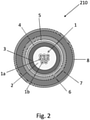
- FIG.2 show a cross-sectional view of an optical cable according to the present disclosure.
- the optical cable 210 comprises a plurality of optical fibers 1.
- Each optical fiber 1 comprises an optical waveguide 1a (as transmissive core comprising a glass core and a glass cladding) surrounded by one or more polymeric coatings 1b.
- the plurality of optical fibers 1 is housed in a tube 3 which can be of metallic or polymeric material.
- the tube 3 also contains a water-blocking compound 2, typically a gel.
- the tube 3 is surrounded by an aramid yarn layer 4 surrounded, in turn by a polyethylene layer 5.
- a steel tape armour 6 surrounds the polyethylene layer 5.
- the polymeric coating/s 1b of the optical fibers 1, the tube 3, the aramid yarn layer 4, the polyethylene layer 5 and the steel tape armour 6 are protecting layers according to the present disclosure.
- a jacket 7 is provided made, for example, of LS0H material and surrounded by an external semi-conductive layer 8 according to the present disclosure.
- the present description also applies to the case wherein the jacket of the cable has two or more polymeric layers.
- the electrical cable or the optical cable according to the present disclosure may be manufactured based on cable manufacturing techniques known to those skilled in the art.
- the insulated cable core of the electrical cable may be formed using conventional processes with materials, layers, and thicknesses chosen to comply with voltage requirements and needs of the particular application for the cable.
Description
- The present disclosure relates to a cable, such as an electrical cable or
- an optical cable having an outermost layer which is semi-conductive. In particular,
- the electrical cable is a medium voltage or high voltage cable for power transmission or distribution.
- The structure of electrical cables for power transmission or distribution may vary according to the intended applications. In general, electrical cables may be categorized as low voltage (LV), medium voltage (MV), or high voltage (HV). In the present description and claims, "low voltage" is used to indicate a voltage up to 1 kV, "medium voltage" is used to indicate a voltage of from 5 kV to 46 kV, and "high voltage" is used to indicate a voltage greater than 46 kV.
- The cable generally comprises a transmissive core and a jacket having at least an outermost polymeric layer.
- For MV and HV electrical cables, the transmissive core is an insulated core comprising, from interior to exterior, at least one electrical electrically conductive element, an electrical insulation system, and a metallic screen. Additional layers may also be present. The electrical insulation system generally comprises an inner semi-conductive layer, an electrically insulating layer and an outer semi-conductive layer.
- For an optical cable, the transmissive core comprises at least one optical waveguide, and the cable comprises a plurality of protecting layers under the jacket and surrounding the transmissive core.
-
WO 2017/084709 discloses an electric power cable. -
US 2010/0078194 discloses a medium or high voltage cable comprising a conductive core, an inner semiconductive layer, an insulating layer, an outer semiconductive layer, neutral conductors and a jacket, in which at least one of the inner semiconductive layer, the outer semiconductive layer and the jacket comprises a carbon nanotube composition. -
KR 2016 0121873 - Jacket integrity tests are important because any defect in and/or damage to the jacket of the cable constitutes a discontinuity in the polymeric layer, which can ultimately cause electrical failure as the transmissive cores are no longer protected by the jacket as originally designed. For example, the presence of a cut in the jacket of the cable represents a preferential route for the entry of water or moisture to the interior (i.e. towards the core) of the cable, which can cause significant problems including short circuit and corrosion of the metal conductors.
- The entry of water into a cable is particularly undesirable since, in the absence of suitable solutions provided to stop the leak, once the water has entered, it could run freely inside the cable. This particularly causes damage in terms of the integrity of the cable, since corrosion problems (affecting, for example, the armoring, if present, or the metal screen) may arise inside the cable. In the case of an electrical cable, problems of premature ageing with degradation of the electrical properties of the insulating system may arise. This phenomenon of premature ageing is better known by the term "water treeing" and gives rise to branched shaped ("trees") micro-fractures due to the combined action of the electrical field generated by the passage of current in the conductor, and of the moisture that has penetrated into the insulating layer. In the case of an optical cable, the presence of water can impair the signal transport capacity of the optical waveguides.
- As disclosed by
US 9 064 618 - If the jacket has a defect and/or damage such as to create an electrically conductive path in the thickness of the jacket between the electrodes in the test, a short-circuit condition will exist and an overcurrent will be produced. The establishment of the overcurrent condition thus enables a person skilled in the art to confirm the presence of damage to and/or a defect in the jacket of the cable.
- In general, the DC withstand test of the jacket is performed directly at the production plant after the process for producing the cable. Sometimes, the DC withstand test is also repeated once the cable has been installed, so as to check for any evidence of damage produced in the outer jacket due to the laying operations of the cable. Repeating the testing once the cable has been installed can be highly desirable, especially in the case of underground installations in which the cable is placed directly in the ground without the aid of conduits to contain it.
- Graphite has traditionally been used for the outer semi-conductive layer because it can be easily removed at one end of the cable, as required for conducting the DC withstand test. However, after the cable has been buried, graphite may offer problems during maintenance testing because the graphite is messy and it may have rubbed off during installation.
- Instead of applying graphite around the jacket, a thin layer of semi-conductive polymeric material may alternatively be extruded over the jacket.
- Typically, the jacket and the outer semi-conductive layer are both generally black and, thus hardly distinguishable. The jacket is usually black to aid with sunlight resistance. The semi-conductive layer is usually black, as a common and cheap way for making a semi-conductive layer is to add carbon black (defeating any other colorants) to a polyethylene material.
- It is also known to make the jacket non-black for particular applications (e.g. different colored jackets in order to identify one cable from another and/or to meet a specific country law that requires different colors for different cable types; e.g. red color for MV cables).
- When colored jackets are used, there is the problem that a typical black colored semi-conductive layer cannot be applied over the jacket in order to perform the integrity test, as it would nullify the purpose of the colored jacket.
- In this context,
US 9 064 618 - A jacket integrity test can also be applied to optical cables. Optical cables can equally suffer performance decline or impairment in case of damage to the outer jacket, for example because of water penetration. Optical cables can be successfully tested by, for example, the above-mentioned jacket integrity standard when they comprise at least one metallic element in a radially internal position with respect to the outer jacket, such as armour, strength elements or tube housing optical waveguides.
- The Applicant notes that the electrically conductive polymers proposed by
US 9 064 618 - In view of the above, an object of the present disclosure is that of providing a cable with an external semi-conductive layer, which has reduced cost and improved compatibility of the materials of the jacket and the external semi-conductive layer, and that enables the provision of an external semi-conductive layer of the color requested by the standard and/or by the customer.
- The Applicant also observes that, in general, it is useful that the different elements of a cable are visually distinguishable from each other.
- This can be advantageous, for example, when making cable joints where the electrical conductors of two electrical cables are jointed to each other. To perform the joint, the elements of the two cables external to the electrical conductors are removed to enable said jointing. Then, the removed external elements must be restored at the joint, taking care that the restored elements are jointed to the diverse external elements of the two cables to match them (e.g. in position, thickness etc.) as exactly as possible. This operation is eased when the cable elements are visually distinguishable from each other, typically by color.
- Accordingly, an ancillary object of the present disclosure is that of providing a cable with an external semi-conductive layer visually distinguishable from the jacket, even when the latter is black. Accordingly, in a first aspect the present disclosure relates to a cable according to
claim 1. - As specified in the first option of
claim 1, the cable of the present disclosure is an electrical cable for power transmission or distribution and the transmissive core is an insulated core comprising an electrically conductive element surrounded by an electrical insulating system and a metallic screen. The electrical insulating system comprises an inner semi-conductive layer, an insulating layer and an outer semi-conductive layer. - As specified in the second option of
claim 1, the cable of the present disclosure is an optical cable for telecommunication, the transmissive core comprises at least one optical waveguide, and the cable comprises a plurality of protecting layers under the jacket and surrounding the transmissive core, of which at least one is metallic. Examples of protecting layers are polymeric coating, buffer, polymeric or metal tube, water-blocking filler, metallic water barrier, flame retardant polymeric layer, fire-resistant glass or mica layers, metal armour in form of wires or optionally corrugated sheath. - The optical waveguide comprises a glass core and a glass cladding.
- The Applicant notes that the use of a base polymer material made, for example, of an ethylene homopolymer, ethylene copolymer or PVC enables to obtain a cable which has reduced cost (thanks to the fact that such a base polymer material is cheaper with respect to the electrically conductive polymers used by
US 9 064 618 - At the same time, thanks to its high electrically conductive properties, the carbon nanotubes as electrically conductive filler can be used in a minimal percentage that, on the one side, is sufficient to provide the base polymer material of the external semi-conductive layer with the required electrical conductivity for integrity tests and, on the other side, does not affect the natural color thereof.
- Thus, the base polymer material of the external semi-conductive layer of the present disclosure can be made suitably conductive while keeping its natural color which, in the case of polyethylene material, is substantially transparent.
- Moreover, depending on the specific needs, it is possible to make the external semi-conductive layer colored, by adding a colorant to the base polymer material.
- In this way, either in the case of a colored semi-conductive layer or in the case of a transparent semi-conductive layer with a colored jacket, it is possible to obtain a cable which has - as a whole - a colored exterior appearance even other than black (e.g. to meet customer and/or law requirements) to which an integrity test can be performed.
- In the present description and claims, the expression "transparent" in connection with a material of a cable layer is used to indicate that the material enables one to see through it, in particular to see the color of the underlying layer through it.
- The present disclosure, in at least one of the disclosed aspects, can be implemented according to one or more of the following embodiments, optionally combined together.
- In an embodiment, the electrically conductive filler comprises carbon nanotubes in an amount of at least 0.05wt% with respect to the total weight of the semi-conductive layer composition. The electrically conductive filler comprises carbon nanotubes in an amount of 0.5wt% at most. The Applicant observed that this amount of carbon nanotubes can be sufficiently high to provide a semi-conductive layer with the electrical conductivity required, for example, to perform an integrity test, and at the same time could maintain the natural appearance or coloring of the base polymer material visually perceivable. For the sake of comparison, it is noted that to obtain similar values of electrical conductivity with carbon black as electrically conductive filler, an amount of 20-25wt%, with respect to the weight of the semi-conductive composition is required. Such an amount completely changes the natural appearance or the coloring of the base polymer material of a semi-conductive layer by blackening it.
- In an embodiment, the external semi-conductive layer of the present cable has an electrical conductivity of at least 10-2 S/cm (corresponding to a resistivity of 1 Ω∗m) as measured, for example, according
IEC 60093, 2nd ed, 1980 (volume resistivity). - In an embodiment, the external semi-conductive layer of the present cable can have an electrical conductivity of 10-1 S/cm (corresponding to resistivity of 10-1 Ω∗m) at most.
- The electrically conductive filler consists of carbon nanotubes only.
- The electrically conductive filler of the present disclosure is devoid of carbon black. This to avoid altering, and in particular, blackening, the natural appearance or the coloring of the base polymer material of the semi-conductive layer.
- In an embodiment, the electrically conductive filler comprises an amount of carbon nanotubes suitable to provide a conductivity of at least 10-2 S/cm (corresponding to a resistivity of 1 Ω∗m).
- In an embodiment, the electrically conductive filler comprises an amount of carbon nanotubes adapted to achieve a conductivity of 10-1 S/cm (corresponding to resistivity of 10-1 Ω∗m) at most.
- The Applicant observed that the above values of conductivity are suitable to perform a jacket integrity test wherein a DC voltage of about 150 V/mil (6kV/mm) and up to a maximum of 24kV is applied between the metallic screen and the external semi-conductive layer to verify the integrity of the jacket.
- In an embodiment, a thickness of the semi-conductive layer is up to 20% of a combined thickness of the jacket and the semi-conductive layer.
- In an embodiment, the external semi-conductive layer of the cable is different in color from the outermost polymeric layer of the jacket, thus visually distinguishable therefrom. For example, the external semi-conductive layer can have the appearance of the natural base polymer material (substantially transparent in the case of polyethylene, white in the case of PVC or in case of polyethylene charged with a filler), while the jacket can be black (to aid with sunlight resistance) or of any other color (e.g. to meet customer and/or law requirements, like in the case of MV cables). In another example, the external semi-conductive layer can be colored while the jacket can be left uncolored (as hidden from the sunlight) or colored in a different color.
- The external semi-conductive layer is of a color other than black.
- In an embodiment, the external semi-conductive layer also comprises a colorant. The Applicant noted that the above cited amount of carbon nanotubes is sufficiently low to guarantee that the color imparted to the base polymer material by the colorant is maintained and not blackened by the electrically conductive filler.
- In an embodiment, the external semi-conductive layer comprises the colorant in an amount of at least 0.01 wt%, with respect to the total weight of the semi-conductive layer composition.
- In an embodiment, the external semi-conductive layer comprises the colorant in an amount of 2.5 wt% at most, for example of from 0.015 wt% to 1.2 wt%, with respect to the total weight of the semi-conductive layer composition. Colorants suitable for the polymeric material of the external semi-conductive layer can be readily selected by the skilled person. See, for example, Fundamentals of Color and Additives, Utilization of Color & Additive Concentrates, Clariant International Ltd, 2013.
- The jacket underlying the external semi-conductive layer can be of any color. When the external semi-conductive layer is transparent because of the lack of any coloring agent in a material per se transparent, like polyethylene, the color of the jacket is visible from the outside and can be that required by the customer and/or by the standard.
- In an embodiment, the jacket and the external semi-conductive layer are of substantially the same color.
- The carbon nanotubes may be single walled or few walled (e.g. 2 or 3 walls). The Applicant notes that with respect to multi walled (e.g. more than 3 walls) carbon nanotubes, single walled or few walled carbon nanotubes can display higher conductivity values at the same concentration.
- In an embodiment, the external semi-conductive layer can include UV additives to improve sunlight resistance for the cable, with the provision that it preserves the color of the external semi-conductive layer unchanged. Examples of UV additives for sunlight resistance are based on titanium dioxide.
- The base polymer material of the external semi-conductive layer according to the present disclosure is per se non-electrically conductive.
- In an embodiment, the base polymer material of the external semi-conductive layer may be selected from: polyethylene (for example, high density polyethylene, HDPE), ethylene propylene rubber (EPR), ethylene vinyl acetate (EVA) or a mixture thereof, such polymers or polymer mixtures being possibly low smoke zero halogen (LS0H) material, charged with an inorganic non-halogenated flame retardant filler, like magnesium hydroxide. In another embodiment, the base polymer material of the external semi-conductive layer is made of PVC.
- The jacket is substantially dielectric even when made of a material containing a filler.
- In an embodiment, the jacket is made of a polymer material selected from low density polyethylene (LDPE), medium density polyethylene (MDPE), high density polyethylene (HDPE), polyvinyl chloride (PVC), or a LS0H material.
- In an embodiment, the jacket is monolayered with the outermost polymeric layer being its only layer. Alternatively, the jacket may have two or more polymeric layers, one being an innermost polymeric layer and another being the outermost polymeric layer.
- The cable can be an electrical DC or AC cable.
- In an embodiment, the cable is terrestrial. The terrestrial cable can be at least in part buried, optionally in a pipe, or positioned in vaults or tunnels.
- The features and advantages of the present disclosure will be made apparent by the following detailed description of some exemplary embodiments thereof, provided merely by way of non-limiting examples, description that will be conducted by making reference to the attached drawings, wherein
-
FIG. 1 is a cross-sectional view of an electrical cable according to the present disclosure; and -
FIG. 2 is a cross-sectional view of an optical cable according to the present disclosure - Referring to
FIG. 1 , an electrical cable 110 comprises an insulated cable core (as transmissive, insulated core) comprising a conductor 12 (as electrically conductive element), an extrudedinner semi-conductive layer 14 encircling theconductor 12, an extruded electrical insulatinglayer 16 surrounding theinner semi-conductive layer 14, an extrudedouter semi-conductive layer 18, and ametallic screen 20. Additional components such as water swellable conductive or non-conductive tapes or yarns, rip cords, and the like may be included in the insulated cable core, as is known in the art. The optional water swellable tape or yarn may be capable of acting as a barrier to the penetration of water into the insulated core of the cable. -
Conductor 12 may be a conductor of the electrical type or of the mixed electrical/optical type. An electrical type conductor may be made of copper, aluminum, or aluminum alloy. - Inner
semi-conductive layer 14, the electrical insulatinglayer 16 and theouter semi-conductive layer 18 encirclingconductor 12 may be made of any polymeric material known to those skilled in the art for semi-conductive shields and typically extruded overconductor 12, for example, polyolefins (homopolymers or copolymers of various olefins), olefin/ethylenically unsaturated ester copolymers, polyesters, polyethers, polyether/polyester copolymers, and blends thereof. Examples of such polymers are: polyethylene (PE), such as linear low-density polyethylene (LLDPE); polypropylene (PP); propylene/ethylene thermoplastic copolymers; ethylene-propylene rubbers (EPR) or ethylene-propylene-diene rubbers (EPDM); natural rubbers; butyl rubbers; ethylene/vinyl acetate (EVA) copolymers; ethylene/methyl acrylate (EMA) copolymers; ethylene/ethyl acrylate (EEA) copolymers; ethylene/butyl acrylate (EBA) copolymers; ethylene/a-olefin copolymers, and the like. In the case of the inner and outersemi-conductive layers - An exemplary thickness for electrical insulating
layer 16 can be from 3 to 30 mm. -
Metallic screen 20 is formed aroundouter semi-conductive layer 18 and may be copper concentric neutral wires, aluminum, steel, lead, or copper or aluminum laminated tape, or both.Metallic screen 20 can be a tape, which is longitudinally folded or spirally wound to form a circumferentially and longitudinally continuous layer, in a manner well known in the art.Metallic screen 20 may be a continuous tubular component or a metal sheet folded on itself and welded or sealed to form the tubular component. - Electrical cable 110 further includes a
jacket 22 formed around the transmissive core.Jacket 22 is made of a polymeric material and may be formed through pressure extrusion.Jacket 22 serves to protect the cable from environmental, thermal, and mechanical hazards and substantially encapsulates the insulated cable core. Jacket thickness may depend on factors such as cable rating and conductor size and is identified in industry specifications, as well known to those skilled in the art. As a general guide, the thickness ofjacket 22 may be in the range of 1.78-4.57 mm. - Referring to
FIG. 1 , electrical cable 110 further includes anexternal semi-conductive layer 24 also applied by extrusion to surround and directly contacting thejacket 22. Theexternal semi-conductive layer 24 is made of a composition comprising an electrically conductive filler, as from the present disclosure, that enables it to be used for performing a jacket integrity test, such as the above mentioned DC withstand test, onjacket 22. - The composition of the
semi-conductive layer 24 comprises a base polymer material wherein carbon nanotubes as electrically conductive filler are dispersed. - This allows the
external semi-conductive layer 24 to be transparent or of any color to meet customer and/or law requirements. - A color difference between the
jacket 22 and theexternal semi-conductive layer 24 helps to make the two layers distinguishable from each other to a field technician. When cutting off a portion of theexternal semi-conductive layer 24 at a cable end (e.g. to joint two cables), the technician can readily detect the boundary between thesemi-conductive layer 24 and the different material underlying it. - The thickness of the
external semi-conductive layer 24 may be up to 20% of the overall thickness of the combined thickness oflayers FIG.2 show a cross-sectional view of an optical cable according to the present disclosure. Theoptical cable 210 comprises a plurality ofoptical fibers 1. Eachoptical fiber 1 comprises anoptical waveguide 1a (as transmissive core comprising a glass core and a glass cladding) surrounded by one or morepolymeric coatings 1b. - The plurality of
optical fibers 1 is housed in atube 3 which can be of metallic or polymeric material. Thetube 3 also contains a water-blockingcompound 2, typically a gel. - The
tube 3 is surrounded by anaramid yarn layer 4 surrounded, in turn by apolyethylene layer 5. - A
steel tape armour 6 surrounds thepolyethylene layer 5. - The polymeric coating/s 1b of the
optical fibers 1, thetube 3, thearamid yarn layer 4, thepolyethylene layer 5 and thesteel tape armour 6 are protecting layers according to the present disclosure. - Around the
armour 6, ajacket 7 is provided made, for example, of LS0H material and surrounded by anexternal semi-conductive layer 8 according to the present disclosure. - It is noted that when a colored cable has to be obtained, it is suitable to obtain it by coloring the external semi-conductive layer rather than having the jacket of the desired color and the external semi-conductive layer transparent. As the external semi-conductive later is usually less thick than the jacket, a lower quantity of colorant is required to obtain the desired color.
- It is noted that, even if not shown, the present description also applies to the case wherein the jacket of the cable has two or more polymeric layers.
- In this case, the structural and functional features described above with reference to jacket and external semi-conductive layer applies to the outermost layer of jacket and external semi-conductive layer.
- The electrical cable or the optical cable according to the present disclosure may be manufactured based on cable manufacturing techniques known to those skilled in the art. In particular, the insulated cable core of the electrical cable may be formed using conventional processes with materials, layers, and thicknesses chosen to comply with voltage requirements and needs of the particular application for the cable.
Claims (14)
- Cable (110, 210) comprising:- a transmissive core (1a, 12, 14, 16, 18, 20);- a jacket (7, 22) surrounding the transmissive core (1a, 12, 14, 16, 18, 20), the jacket (7, 22) having at least an outermost polymeric layer; and- an external semi-conductive layer (8, 24) around and in direct contact with the outermost polymeric layer of the jacket (7, 22), the external semi-conductive layer (8, 24) being made of a composition comprising a base polymer material and an electrically conductive filler,wherein the electrically conductive filler comprises carbon nanotubes and the cable (110, 210) is:- an electrical cable (110) and the transmissive core is an insulated core comprising an electrically conductive element (12) surrounded by an electrical insulating system (14, 16, 18) and a metallic screen (20), the electrical insulating system (14, 16, 18) comprising an inner semi-conductive layer (14), an insulating layer (16) and an outer semi-conductive layer (18), or- an optical cable (210), the transmissive core comprising at least one optical waveguide (1a), and the cable (210) comprises a plurality of protecting layers (1b, 3, 4, 5, 6) surrounding the transmissive core (1a), of which at least one is metallic, the plurality of protecting layers (3, 4, 5, 6) being surrounded by the jacket (7),characterized in that the electrically conductive filler consists of carbon nanotubes only in an amount up to 0.5 wt% with respect to the total weight of the semi-conductive layer composition, and the external semi-conductive layer (8, 24) is of a color other than black.
- Cable (110, 210) according to claim 1, wherein the external semi-conductive layer (8, 24) has the appearance of the natural base polymer material.
- Cable (110, 210) according to claim 1, wherein the external semi-conductive layer (8, 24) is transparent.
- Cable (110, 210) according to claim 1, wherein the external semi-conductive layer (8, 24) comprises a colorant.
- Cable (110, 210) according to claim 1, wherein the jacket (7, 22) is black or of any other color.
- Cable (110, 210) according to claim 1, wherein the electrically conductive filler comprises carbon nanotubes in an amount of at least 0.05 wt% with respect to the total weight of the semi-conductive layer composition.
- Cable (110, 210) according to claim 1, wherein the external semi-conductive layer (8, 24) has a conductivity of at least 10-2 S/cm.
- Cable (110, 210) according to claim 4, wherein the external semi-conductive layer (8, 24) comprises the colorant in an amount of at least 0.01 wt% with respect to the total weight of the semi-conductive layer composition.
- Cable (110, 210) according to claim 4, wherein the external semi-conductive layer (8, 24) comprises the colorant in an amount of at most 2.5 wt% with respect to the total weight of the semi-conductive layer composition.
- Cable (110, 210) according to claim 1, wherein the semi-conductive layer (8, 24) is different in color from the outermost polymeric layer of the jacket (7, 22).
- Cable (110, 210) claim 1, wherein the carbon nanotubes are single walled or few walled.
- Cable (110, 210) according to claim 1, wherein a thickness of the external semi-conductive layer (8, 24) is up to 20% of a combined thickness of the jacket (7, 22) and the external semi-conductive layer (8, 24).
- Cable (110, 210) according to claim 1, wherein the external semi-conductive layer (8, 24) includes UV additives.
- Cable (110, 210) according to claim 1, wherein the base polymer material of the external semi-conductive layer (8, 24) is selected from:polyethylene, ethylene propylene rubber, ethylene vinyl acetate or a mixture thereof, optionally charged with an inorganic non-halogenatedflame retardant filler; or wherein the base polymer material of the external semi-conductive layer (8, 24) is polyvinyl chloride.
Applications Claiming Priority (1)
| Application Number | Priority Date | Filing Date | Title |
|---|---|---|---|
| IT102019000004699A IT201900004699A1 (en) | 2019-03-29 | 2019-03-29 | Cable with semi-conducting outermost layer |
Publications (2)
| Publication Number | Publication Date |
|---|---|
| EP3715928A1 EP3715928A1 (en) | 2020-09-30 |
| EP3715928B1 true EP3715928B1 (en) | 2022-02-09 |
Family
ID=66776819
Family Applications (1)
| Application Number | Title | Priority Date | Filing Date |
|---|---|---|---|
| EP20162931.8A Active EP3715928B1 (en) | 2019-03-29 | 2020-03-13 | Cable with semi-conducting outermost layer |
Country Status (8)
| Country | Link |
|---|---|
| US (1) | US11651870B2 (en) |
| EP (1) | EP3715928B1 (en) |
| CN (1) | CN111755148A (en) |
| AU (1) | AU2020201912A1 (en) |
| BR (1) | BR102020006083A2 (en) |
| CA (1) | CA3077001A1 (en) |
| ES (1) | ES2912724T3 (en) |
| IT (1) | IT201900004699A1 (en) |
Families Citing this family (1)
| Publication number | Priority date | Publication date | Assignee | Title |
|---|---|---|---|---|
| WO2023211351A1 (en) * | 2022-04-27 | 2023-11-02 | Habia Cable Aktiebolag | A multi-layered lightweight high-voltage electrical cable, a method of stripping an electrical cable, and a kit |
Family Cites Families (19)
| Publication number | Priority date | Publication date | Assignee | Title |
|---|---|---|---|---|
| US5018825A (en) * | 1989-06-14 | 1991-05-28 | Bicc Public Limited Company | Overhead optical transmission system |
| US5042903A (en) * | 1990-07-30 | 1991-08-27 | Westinghouse Electric Corp. | High voltage tow cable with optical fiber |
| US6599961B1 (en) * | 2000-02-01 | 2003-07-29 | University Of Kentucky Research Foundation | Polymethylmethacrylate augmented with carbon nanotubes |
| US20040109652A1 (en) * | 2002-12-04 | 2004-06-10 | Alcatel | Fiber optic cables with a hydrogen absorbing material |
| WO2006073454A2 (en) * | 2004-04-28 | 2006-07-13 | University Of South Florida | Polymer/carbon nanotube composites, methods of use and methods of synthesis thereof |
| RU2389739C2 (en) * | 2005-08-08 | 2010-05-20 | Кабот Корпорейшн | Polymer compositions containing nanotubes |
| CN101090586B (en) * | 2006-06-16 | 2010-05-12 | 清华大学 | Nano flexible electrothermal material and heating device containing the nano flexible electrothermal material |
| US7496258B1 (en) * | 2007-11-09 | 2009-02-24 | Schlumberger Technology Corporation | Hydrocarbon monitoring cable |
| FR2942673B1 (en) * | 2009-02-27 | 2011-04-01 | Nexans | HIGH VOLTAGE ELECTRICAL CABLE |
| AU2010354054A1 (en) | 2010-05-27 | 2012-12-06 | Prysmian Power Cables And Systems Usa, Llc | Electrical cable with semi-conductive outer layer distinguishable from jacket |
| FR2972560A1 (en) * | 2011-03-08 | 2012-09-14 | Nexans | ELECTRICAL CABLE WITH MEDIUM OR HIGH VOLTAGE |
| US9784049B2 (en) * | 2013-12-28 | 2017-10-10 | Trican Well Service, Ltd. | Carbon fiber based tubing encapsulated cable |
| CN104297875B (en) * | 2014-10-13 | 2017-07-07 | 中天科技海缆有限公司 | A kind of high pressure optoelectronic composite cable equipotential fiber unit and preparation method thereof |
| KR20160121873A (en) * | 2015-04-13 | 2016-10-21 | 엘에스전선 주식회사 | Power cable |
| CN104893180A (en) * | 2015-06-13 | 2015-09-09 | 合肥和安机械制造有限公司 | CNT (carbon nano-tube)-based polymer blended colored cable material and preparation method thereof |
| WO2017084709A1 (en) * | 2015-11-19 | 2017-05-26 | Abb Hv Cables (Switzerland) Gmbh | Electric power cable and process for the production of electric power cable |
| WO2018120048A1 (en) * | 2016-12-30 | 2018-07-05 | 德尔福派克电气系统有限公司 | Shield cable having electromagnetic shielding member made of composite material |
| KR102468594B1 (en) * | 2017-07-07 | 2022-11-17 | 엘에스전선 주식회사 | Shaped Filler For Cable And Submarine Cable Having The Same |
| US10788622B2 (en) * | 2018-10-03 | 2020-09-29 | Ofs Fitel, Llc | Optically conductive hybrid cable |
-
2019
- 2019-03-29 IT IT102019000004699A patent/IT201900004699A1/en unknown
-
2020
- 2020-03-13 EP EP20162931.8A patent/EP3715928B1/en active Active
- 2020-03-13 ES ES20162931T patent/ES2912724T3/en active Active
- 2020-03-17 AU AU2020201912A patent/AU2020201912A1/en active Pending
- 2020-03-24 CA CA3077001A patent/CA3077001A1/en active Pending
- 2020-03-26 BR BR102020006083-0A patent/BR102020006083A2/en unknown
- 2020-03-27 CN CN202010226899.4A patent/CN111755148A/en active Pending
- 2020-03-27 US US16/833,233 patent/US11651870B2/en active Active
Also Published As
| Publication number | Publication date |
|---|---|
| ES2912724T3 (en) | 2022-05-27 |
| US20200312488A1 (en) | 2020-10-01 |
| IT201900004699A1 (en) | 2020-09-29 |
| US11651870B2 (en) | 2023-05-16 |
| EP3715928A1 (en) | 2020-09-30 |
| AU2020201912A1 (en) | 2020-10-15 |
| BR102020006083A2 (en) | 2020-10-13 |
| CA3077001A1 (en) | 2020-09-29 |
| CN111755148A (en) | 2020-10-09 |
Similar Documents
| Publication | Publication Date | Title |
|---|---|---|
| CA2799716C (en) | Electrical cable with semi-conductive outer layer distinguishable from jacket | |
| CA2662455C (en) | Subsea umbilical | |
| US10606005B1 (en) | Optical cables having an inner sheath attached to a metal tube | |
| AU2008360212B2 (en) | Optical earth cable for underground use | |
| AU8859598A (en) | Optical fibre cable having high tracking resistance | |
| RU193823U1 (en) | Power cable | |
| EP3715928B1 (en) | Cable with semi-conducting outermost layer | |
| AU2019261727A1 (en) | Fire resistant signalling cable for railway applications | |
| RU167142U1 (en) | POWER CABLE, NOT DISTRIBUTING COMBUSTION, WITH SECTOR CONDUCTORS AND INSULATION FROM CROSSED POLYETHYLENE | |
| KR102499648B1 (en) | High voltage DC power cable joint system | |
| RU164397U1 (en) | THREE-WAY POWER CABLE WITH INTEGRATED POLYETHYLENE | |
| CN209880229U (en) | Waterproof directly-buried photovoltaic cable | |
| KR20200101857A (en) | Jointing Structure Of Power Cable | |
| KR20210081956A (en) | Marine cable | |
| RU215269U1 (en) | Explosion Proof Sealed Power Cable | |
| KR102186584B1 (en) | Copper-mylar tape for aerial cable and manufacturing method thereof | |
| RU216407U1 (en) | Explosion-proof control cable | |
| CN211294724U (en) | Mixed cable | |
| CN216487434U (en) | Medium-voltage high-strength multiple waterproof cable for urban rail transit | |
| Bayer et al. | Chemical-moisture barrier cable-concept and practice | |
| RU57954U1 (en) | ELECTRICAL CABLE | |
| RU66594U1 (en) | SHIP CABLE | |
| Lee et al. | A development of improved underground distribution power cables | |
| Voltz et al. | IEEE 1242-Guide for Specifying and Selecting Cable for Petrochemical Plants-what's in it and how will it help you |
Legal Events
| Date | Code | Title | Description |
|---|---|---|---|
| PUAI | Public reference made under article 153(3) epc to a published international application that has entered the european phase |
Free format text: ORIGINAL CODE: 0009012 |
|
| STAA | Information on the status of an ep patent application or granted ep patent |
Free format text: STATUS: THE APPLICATION HAS BEEN PUBLISHED |
|
| AK | Designated contracting states |
Kind code of ref document: A1 Designated state(s): AL AT BE BG CH CY CZ DE DK EE ES FI FR GB GR HR HU IE IS IT LI LT LU LV MC MK MT NL NO PL PT RO RS SE SI SK SM TR |
|
| AX | Request for extension of the european patent |
Extension state: BA ME |
|
| STAA | Information on the status of an ep patent application or granted ep patent |
Free format text: STATUS: REQUEST FOR EXAMINATION WAS MADE |
|
| 17P | Request for examination filed |
Effective date: 20210323 |
|
| RBV | Designated contracting states (corrected) |
Designated state(s): AL AT BE BG CH CY CZ DE DK EE ES FI FR GB GR HR HU IE IS IT LI LT LU LV MC MK MT NL NO PL PT RO RS SE SI SK SM TR |
|
| GRAP | Despatch of communication of intention to grant a patent |
Free format text: ORIGINAL CODE: EPIDOSNIGR1 |
|
| STAA | Information on the status of an ep patent application or granted ep patent |
Free format text: STATUS: GRANT OF PATENT IS INTENDED |
|
| RIC1 | Information provided on ipc code assigned before grant |
Ipc: C08K 5/00 20060101ALN20210811BHEP Ipc: C08K 3/016 20180101ALN20210811BHEP Ipc: C08K 3/014 20180101ALN20210811BHEP Ipc: H01B 9/00 20060101ALN20210811BHEP Ipc: G01R 31/12 20200101ALN20210811BHEP Ipc: H01B 7/36 20060101ALN20210811BHEP Ipc: C08K 3/04 20060101ALI20210811BHEP Ipc: H01B 1/24 20060101ALI20210811BHEP Ipc: H01B 9/02 20060101ALI20210811BHEP Ipc: G02B 6/44 20060101AFI20210811BHEP |
|
| INTG | Intention to grant announced |
Effective date: 20210906 |
|
| RIN1 | Information on inventor provided before grant (corrected) |
Inventor name: DE RAI, LUCA GIORGIO MARIA |
|
| GRAS | Grant fee paid |
Free format text: ORIGINAL CODE: EPIDOSNIGR3 |
|
| GRAA | (expected) grant |
Free format text: ORIGINAL CODE: 0009210 |
|
| STAA | Information on the status of an ep patent application or granted ep patent |
Free format text: STATUS: THE PATENT HAS BEEN GRANTED |
|
| AK | Designated contracting states |
Kind code of ref document: B1 Designated state(s): AL AT BE BG CH CY CZ DE DK EE ES FI FR GB GR HR HU IE IS IT LI LT LU LV MC MK MT NL NO PL PT RO RS SE SI SK SM TR |
|
| REG | Reference to a national code |
Ref country code: GB Ref legal event code: FG4D |
|
| REG | Reference to a national code |
Ref country code: CH Ref legal event code: EP Ref country code: AT Ref legal event code: REF Ref document number: 1467857 Country of ref document: AT Kind code of ref document: T Effective date: 20220215 |
|
| REG | Reference to a national code |
Ref country code: DE Ref legal event code: R096 Ref document number: 602020001775 Country of ref document: DE |
|
| REG | Reference to a national code |
Ref country code: IE Ref legal event code: FG4D |
|
| REG | Reference to a national code |
Ref country code: LT Ref legal event code: MG9D |
|
| REG | Reference to a national code |
Ref country code: NL Ref legal event code: MP Effective date: 20220209 |
|
| REG | Reference to a national code |
Ref country code: AT Ref legal event code: MK05 Ref document number: 1467857 Country of ref document: AT Kind code of ref document: T Effective date: 20220209 |
|
| PG25 | Lapsed in a contracting state [announced via postgrant information from national office to epo] |
Ref country code: SE Free format text: LAPSE BECAUSE OF FAILURE TO SUBMIT A TRANSLATION OF THE DESCRIPTION OR TO PAY THE FEE WITHIN THE PRESCRIBED TIME-LIMIT Effective date: 20220209 Ref country code: RS Free format text: LAPSE BECAUSE OF FAILURE TO SUBMIT A TRANSLATION OF THE DESCRIPTION OR TO PAY THE FEE WITHIN THE PRESCRIBED TIME-LIMIT Effective date: 20220209 Ref country code: PT Free format text: LAPSE BECAUSE OF FAILURE TO SUBMIT A TRANSLATION OF THE DESCRIPTION OR TO PAY THE FEE WITHIN THE PRESCRIBED TIME-LIMIT Effective date: 20220609 Ref country code: NO Free format text: LAPSE BECAUSE OF FAILURE TO SUBMIT A TRANSLATION OF THE DESCRIPTION OR TO PAY THE FEE WITHIN THE PRESCRIBED TIME-LIMIT Effective date: 20220509 Ref country code: NL Free format text: LAPSE BECAUSE OF FAILURE TO SUBMIT A TRANSLATION OF THE DESCRIPTION OR TO PAY THE FEE WITHIN THE PRESCRIBED TIME-LIMIT Effective date: 20220209 Ref country code: LT Free format text: LAPSE BECAUSE OF FAILURE TO SUBMIT A TRANSLATION OF THE DESCRIPTION OR TO PAY THE FEE WITHIN THE PRESCRIBED TIME-LIMIT Effective date: 20220209 Ref country code: HR Free format text: LAPSE BECAUSE OF FAILURE TO SUBMIT A TRANSLATION OF THE DESCRIPTION OR TO PAY THE FEE WITHIN THE PRESCRIBED TIME-LIMIT Effective date: 20220209 Ref country code: BG Free format text: LAPSE BECAUSE OF FAILURE TO SUBMIT A TRANSLATION OF THE DESCRIPTION OR TO PAY THE FEE WITHIN THE PRESCRIBED TIME-LIMIT Effective date: 20220509 |
|
| PG25 | Lapsed in a contracting state [announced via postgrant information from national office to epo] |
Ref country code: PL Free format text: LAPSE BECAUSE OF FAILURE TO SUBMIT A TRANSLATION OF THE DESCRIPTION OR TO PAY THE FEE WITHIN THE PRESCRIBED TIME-LIMIT Effective date: 20220209 Ref country code: LV Free format text: LAPSE BECAUSE OF FAILURE TO SUBMIT A TRANSLATION OF THE DESCRIPTION OR TO PAY THE FEE WITHIN THE PRESCRIBED TIME-LIMIT Effective date: 20220209 Ref country code: GR Free format text: LAPSE BECAUSE OF FAILURE TO SUBMIT A TRANSLATION OF THE DESCRIPTION OR TO PAY THE FEE WITHIN THE PRESCRIBED TIME-LIMIT Effective date: 20220510 Ref country code: FI Free format text: LAPSE BECAUSE OF FAILURE TO SUBMIT A TRANSLATION OF THE DESCRIPTION OR TO PAY THE FEE WITHIN THE PRESCRIBED TIME-LIMIT Effective date: 20220209 Ref country code: AT Free format text: LAPSE BECAUSE OF FAILURE TO SUBMIT A TRANSLATION OF THE DESCRIPTION OR TO PAY THE FEE WITHIN THE PRESCRIBED TIME-LIMIT Effective date: 20220209 |
|
| PG25 | Lapsed in a contracting state [announced via postgrant information from national office to epo] |
Ref country code: IS Free format text: LAPSE BECAUSE OF FAILURE TO SUBMIT A TRANSLATION OF THE DESCRIPTION OR TO PAY THE FEE WITHIN THE PRESCRIBED TIME-LIMIT Effective date: 20220609 |
|
| PG25 | Lapsed in a contracting state [announced via postgrant information from national office to epo] |
Ref country code: SM Free format text: LAPSE BECAUSE OF FAILURE TO SUBMIT A TRANSLATION OF THE DESCRIPTION OR TO PAY THE FEE WITHIN THE PRESCRIBED TIME-LIMIT Effective date: 20220209 Ref country code: SK Free format text: LAPSE BECAUSE OF FAILURE TO SUBMIT A TRANSLATION OF THE DESCRIPTION OR TO PAY THE FEE WITHIN THE PRESCRIBED TIME-LIMIT Effective date: 20220209 Ref country code: RO Free format text: LAPSE BECAUSE OF FAILURE TO SUBMIT A TRANSLATION OF THE DESCRIPTION OR TO PAY THE FEE WITHIN THE PRESCRIBED TIME-LIMIT Effective date: 20220209 Ref country code: EE Free format text: LAPSE BECAUSE OF FAILURE TO SUBMIT A TRANSLATION OF THE DESCRIPTION OR TO PAY THE FEE WITHIN THE PRESCRIBED TIME-LIMIT Effective date: 20220209 Ref country code: DK Free format text: LAPSE BECAUSE OF FAILURE TO SUBMIT A TRANSLATION OF THE DESCRIPTION OR TO PAY THE FEE WITHIN THE PRESCRIBED TIME-LIMIT Effective date: 20220209 Ref country code: CZ Free format text: LAPSE BECAUSE OF FAILURE TO SUBMIT A TRANSLATION OF THE DESCRIPTION OR TO PAY THE FEE WITHIN THE PRESCRIBED TIME-LIMIT Effective date: 20220209 |
|
| REG | Reference to a national code |
Ref country code: DE Ref legal event code: R097 Ref document number: 602020001775 Country of ref document: DE |
|
| PG25 | Lapsed in a contracting state [announced via postgrant information from national office to epo] |
Ref country code: MC Free format text: LAPSE BECAUSE OF FAILURE TO SUBMIT A TRANSLATION OF THE DESCRIPTION OR TO PAY THE FEE WITHIN THE PRESCRIBED TIME-LIMIT Effective date: 20220209 Ref country code: AL Free format text: LAPSE BECAUSE OF FAILURE TO SUBMIT A TRANSLATION OF THE DESCRIPTION OR TO PAY THE FEE WITHIN THE PRESCRIBED TIME-LIMIT Effective date: 20220209 |
|
| REG | Reference to a national code |
Ref country code: BE Ref legal event code: MM Effective date: 20220331 |
|
| PLBE | No opposition filed within time limit |
Free format text: ORIGINAL CODE: 0009261 |
|
| STAA | Information on the status of an ep patent application or granted ep patent |
Free format text: STATUS: NO OPPOSITION FILED WITHIN TIME LIMIT |
|
| 26N | No opposition filed |
Effective date: 20221110 |
|
| PG25 | Lapsed in a contracting state [announced via postgrant information from national office to epo] |
Ref country code: LU Free format text: LAPSE BECAUSE OF NON-PAYMENT OF DUE FEES Effective date: 20220313 Ref country code: IE Free format text: LAPSE BECAUSE OF NON-PAYMENT OF DUE FEES Effective date: 20220313 |
|
| PG25 | Lapsed in a contracting state [announced via postgrant information from national office to epo] |
Ref country code: SI Free format text: LAPSE BECAUSE OF FAILURE TO SUBMIT A TRANSLATION OF THE DESCRIPTION OR TO PAY THE FEE WITHIN THE PRESCRIBED TIME-LIMIT Effective date: 20220209 Ref country code: BE Free format text: LAPSE BECAUSE OF NON-PAYMENT OF DUE FEES Effective date: 20220331 |
|
| PGFP | Annual fee paid to national office [announced via postgrant information from national office to epo] |
Ref country code: FR Payment date: 20230327 Year of fee payment: 4 |
|
| PGFP | Annual fee paid to national office [announced via postgrant information from national office to epo] |
Ref country code: DE Payment date: 20230329 Year of fee payment: 4 |
|
| PGFP | Annual fee paid to national office [announced via postgrant information from national office to epo] |
Ref country code: IT Payment date: 20230331 Year of fee payment: 4 Ref country code: ES Payment date: 20230403 Year of fee payment: 4 |
|
| REG | Reference to a national code |
Ref country code: CH Ref legal event code: PL |
|
| PG25 | Lapsed in a contracting state [announced via postgrant information from national office to epo] |
Ref country code: LI Free format text: LAPSE BECAUSE OF NON-PAYMENT OF DUE FEES Effective date: 20230331 Ref country code: CH Free format text: LAPSE BECAUSE OF NON-PAYMENT OF DUE FEES Effective date: 20230331 |