EP3715697B1 - Halterungsanordnung und verfahren zur montage von elektrischer ausrüstung zwischen einem monitor und einer tragenden struktur - Google Patents
Halterungsanordnung und verfahren zur montage von elektrischer ausrüstung zwischen einem monitor und einer tragenden struktur Download PDFInfo
- Publication number
- EP3715697B1 EP3715697B1 EP20166529.6A EP20166529A EP3715697B1 EP 3715697 B1 EP3715697 B1 EP 3715697B1 EP 20166529 A EP20166529 A EP 20166529A EP 3715697 B1 EP3715697 B1 EP 3715697B1
- Authority
- EP
- European Patent Office
- Prior art keywords
- back plate
- front plate
- bracket assembly
- extension
- extensions
- Prior art date
- Legal status (The legal status is an assumption and is not a legal conclusion. Google has not performed a legal analysis and makes no representation as to the accuracy of the status listed.)
- Active
Links
Images


Classifications
-
- F—MECHANICAL ENGINEERING; LIGHTING; HEATING; WEAPONS; BLASTING
- F16—ENGINEERING ELEMENTS AND UNITS; GENERAL MEASURES FOR PRODUCING AND MAINTAINING EFFECTIVE FUNCTIONING OF MACHINES OR INSTALLATIONS; THERMAL INSULATION IN GENERAL
- F16M—FRAMES, CASINGS OR BEDS OF ENGINES, MACHINES OR APPARATUS, NOT SPECIFIC TO ENGINES, MACHINES OR APPARATUS PROVIDED FOR ELSEWHERE; STANDS; SUPPORTS
- F16M13/00—Other supports for positioning apparatus or articles; Means for steadying hand-held apparatus or articles
- F16M13/02—Other supports for positioning apparatus or articles; Means for steadying hand-held apparatus or articles for supporting on, or attaching to, an object, e.g. tree, gate, window-frame, cycle
-
- F—MECHANICAL ENGINEERING; LIGHTING; HEATING; WEAPONS; BLASTING
- F16—ENGINEERING ELEMENTS AND UNITS; GENERAL MEASURES FOR PRODUCING AND MAINTAINING EFFECTIVE FUNCTIONING OF MACHINES OR INSTALLATIONS; THERMAL INSULATION IN GENERAL
- F16M—FRAMES, CASINGS OR BEDS OF ENGINES, MACHINES OR APPARATUS, NOT SPECIFIC TO ENGINES, MACHINES OR APPARATUS PROVIDED FOR ELSEWHERE; STANDS; SUPPORTS
- F16M11/00—Stands or trestles as supports for apparatus or articles placed thereon ; Stands for scientific apparatus such as gravitational force meters
- F16M11/02—Heads
- F16M11/04—Means for attachment of apparatus; Means allowing adjustment of the apparatus relatively to the stand
-
- F—MECHANICAL ENGINEERING; LIGHTING; HEATING; WEAPONS; BLASTING
- F16—ENGINEERING ELEMENTS AND UNITS; GENERAL MEASURES FOR PRODUCING AND MAINTAINING EFFECTIVE FUNCTIONING OF MACHINES OR INSTALLATIONS; THERMAL INSULATION IN GENERAL
- F16M—FRAMES, CASINGS OR BEDS OF ENGINES, MACHINES OR APPARATUS, NOT SPECIFIC TO ENGINES, MACHINES OR APPARATUS PROVIDED FOR ELSEWHERE; STANDS; SUPPORTS
- F16M11/00—Stands or trestles as supports for apparatus or articles placed thereon ; Stands for scientific apparatus such as gravitational force meters
- F16M11/02—Heads
- F16M11/04—Means for attachment of apparatus; Means allowing adjustment of the apparatus relatively to the stand
- F16M11/041—Allowing quick release of the apparatus
-
- F—MECHANICAL ENGINEERING; LIGHTING; HEATING; WEAPONS; BLASTING
- F16—ENGINEERING ELEMENTS AND UNITS; GENERAL MEASURES FOR PRODUCING AND MAINTAINING EFFECTIVE FUNCTIONING OF MACHINES OR INSTALLATIONS; THERMAL INSULATION IN GENERAL
- F16M—FRAMES, CASINGS OR BEDS OF ENGINES, MACHINES OR APPARATUS, NOT SPECIFIC TO ENGINES, MACHINES OR APPARATUS PROVIDED FOR ELSEWHERE; STANDS; SUPPORTS
- F16M13/00—Other supports for positioning apparatus or articles; Means for steadying hand-held apparatus or articles
- F16M13/02—Other supports for positioning apparatus or articles; Means for steadying hand-held apparatus or articles for supporting on, or attaching to, an object, e.g. tree, gate, window-frame, cycle
- F16M13/022—Other supports for positioning apparatus or articles; Means for steadying hand-held apparatus or articles for supporting on, or attaching to, an object, e.g. tree, gate, window-frame, cycle repositionable
-
- H—ELECTRICITY
- H05—ELECTRIC TECHNIQUES NOT OTHERWISE PROVIDED FOR
- H05K—PRINTED CIRCUITS; CASINGS OR CONSTRUCTIONAL DETAILS OF ELECTRIC APPARATUS; MANUFACTURE OF ASSEMBLAGES OF ELECTRICAL COMPONENTS
- H05K5/00—Casings, cabinets or drawers for electric apparatus
- H05K5/02—Details
- H05K5/0204—Mounting supporting structures on the outside of casings
-
- F—MECHANICAL ENGINEERING; LIGHTING; HEATING; WEAPONS; BLASTING
- F16—ENGINEERING ELEMENTS AND UNITS; GENERAL MEASURES FOR PRODUCING AND MAINTAINING EFFECTIVE FUNCTIONING OF MACHINES OR INSTALLATIONS; THERMAL INSULATION IN GENERAL
- F16M—FRAMES, CASINGS OR BEDS OF ENGINES, MACHINES OR APPARATUS, NOT SPECIFIC TO ENGINES, MACHINES OR APPARATUS PROVIDED FOR ELSEWHERE; STANDS; SUPPORTS
- F16M2200/00—Details of stands or supports
- F16M2200/02—Locking means
- F16M2200/025—Locking means for translational movement
- F16M2200/028—Locking means for translational movement by positive interaction, e.g. male-female connections
Definitions
- the present invention relates to a mounting device for fixing a display monitor to a support structure, such as a boom arm, wall, or spine of a monitor stand. More specifically, the present invention relates to a mounting bracket assembly for attaching a rear surface of a display monitor to a support structure and for providing a housing in between the display monitor and the support structure to accommodate an electronic device, peripheral device, and/or accessory, within a healthcare environment (e.g., medical room, surgical observation room, operating theater, etc.).
- a healthcare environment e.g., medical room, surgical observation room, operating theater, etc.
- conventional mounting devices are difficult to install and require at least two people to attach the monitor to the supporting structure, especially in the case of a boom arm.
- Conventional mounting solutions also do not account for the need to accommodate other electronic or peripheral components in conjunction with the monitor.
- known mounting devices do not provide space, e.g., an internal cavity or recess, for any electronic component or accessory, including but not limited to, a HD box(es), a video network reception box(es), a cable TV satellite box(es), wired or wireless internet reception device(s), decorders/encoders, etc.
- an additional wall mounted shelf, floor stand, or a separate mounting mechanism separate from the device supporting the TV is required to store and support a peripheral component or accessory.
- the need for mounting additional electronics or peripheral devices in conjunction with the monitor limits the possible placement location of the monitor since additional wall and/or floor space must be considered.
- the wires and cables needed to connect the monitor to the peripheral electronic component can be long and take up significant floor space posing as a potential trip hazard, and thus be objectionable.
- Some mounting mechanisms may be complicated to use with certain boom arms that may interfere with its mounting.
- One mounting solution involves creating new cable covers for each individual monitor brand offered that would provide mounting for equipment. However, it would be expensive to have a cable cover solution for each individual monitor.
- Some mounting mechanisms provide for an electronic component to be held below the bottom of the monitor, thereby exposing the component to possible blood splatter or damage from accidental tugging, pulling, or bumping when attempting to reposition the monitor during a medical operation or procedure.
- Other mounting mechanisms seek to resolve issues related to the healthcare environment by utilizing mounting interface patterns that do not adhere to VESA (Video Electronics Standards Association) interface standards. However, this solution prevents use of the mount across multiple boom arms and multiple monitor configurations.
- VESA Video Electronics Standards Association
- US 2015/0245712 A1 shows a mounting device for accommodating a peripheral device between a TV and a supporting wall.
- the mounting device consists of a rear panel having vertical interconnecting tabs and a front panel with vertical mating tabs.
- the tabs of the respective panels are secured together with conventional hardware, such as screws.
- conventional hardware such as screws.
- the overlap of the vertical tabs does not transfer a weight of the TV to the wall. Instead, the screws must bear the entire weight of the TV (e.g., shear load), which can cause them to break or fracture, thereby rendering the mounting device inoperable.
- the panels have retaining features which form a bottom side or base of the housing.
- Such configuration makes insertion and removal of the peripheral device into/out of the housing difficult as it requires the installer to reach over the top of the TV or to a height above it in order to gain access to the housing. In some situations, it may be necessary to detach the TV and front panel from the rear panel in order to be able to get access to the peripheral device.
- the top of the housing is completely unobstructed. This allows for dust and other contaminant to settle and collect within the housing and on the electronic component. In a medical or healthcare environment, this is unsafe especially with respect to infection control when the peripheral device is removed for maintenance or replacement.
- a mechanism for mounting an LCD TV set at a wall is described.
- a removable support is mechanically connected to the LCD TV set.
- a fixed support is mechanically connected to the wall and receives the removable support.
- the fixed support comprises a longitudinal bent section at either side, a bottom and an interior space.
- a wall plate made of metal includes an upper end, a lower end, a first side and a second side.
- a monitor plate has an upper end, a lower end, a first side, a second side, an inner face opposing the wall plate and an outer face opposing the back or rear of a television monitor.
- a front plate has a front part and integral rectangular flanges at opposite upper and lower parallel sides of the front part, the rectangular flanges extending at 90° from the front part and at the same side thereof.
- a wall plate has a flat front part and upper and lower flanges.
- a base plate is basically a flat plate fastened to a wall and comprises a first fastening piece at its upper edge.
- a connecting plate is primarily a flat plate that allows the secure mounting of a flat panel display device thereon and can be assempled to the base plate.
- the connecting plate is disposed with a first fastening piece at the top side that can engage the first engaging plate of the base plate.
- the mounting system according to the present teachings enables the display monitor to be securely fixed to the supporting structure in a releasable manner, such that the monitor can be subsequently detached and re-attached.
- the present teachings provide for a way to mount a piece of equipment (electronic component, peripheral component, accessory) behind a monitor with little to no mounting surfaces being present.
- the supporting structure e.g., boom arm
- the bracket assembly comprises a back plate configured to mount to the support structure, a back plate extension disposed along one side of the back plate, a front plate configured to mount to the display monitor, and a front plate extension disposed along one side of the front plate.
- the bracket assembly also comprises a contact area or surface formed by the front plate extension overlapping the back plate extension. The overlapping contact area or surface transfers a weight of the monitor to the support structure.
- the bracket assembly comprises a volume that is at least partially enclosed by the front and back plates and extensions for housing an electronic device or component between the display monitor and the support structure.
- the front plate extension projects out in a rearward direction from the front plate, while the back plate extension projects out in a forward direction.
- the front and back plates can be configured to be releasably attached to one another and enable a single person to easily mount the display monitor (e.g., TV, computer monitor, touchscreen, etc.) to the supporting structure (e.g., wall, ceiling, boom arm, etc.).
- the front plate when the plates are attached, is parallel or substantially parallel to the back plate.
- the front plate may be oriented transverse relative to the back plate, such that the volume for the electronic component housing narrows towards the top.
- the contact area or surface is formed between an over surface of the back plate extension and an under surface of the front plate extension.
- the contact area or surface is formed between an edge surface of the back plate extension and the under surface of the front plate extension.
- the over surface and/or edge surface of the back plate extension is angled slightly in an upward direction to more securely hold the display monitor. That is, the angle formed between the back plate and the over surface and/or the edge surface of the back plate extension may be characterized as obtuse.
- the angle between the back plate and the over surface and/or the edge surface is between 90° and 150°.
- the back plate and the over surface and/or the edge surface are perpendicular to one another.
- the front plate extension may be angled slightly in a downward direction to more securely hold the monitor. That is, the angle formed between the front plate and the under surface of the front plate extension may be characterized as acute. For example, the angle between the front plate and the under surface is between than 30° and 90°. In other embodiments, the front plate and the under surface are perpendicular to one another.
- the front plate extension and the back plate extension can be configured so that the under surface (of the front plate extension) and the over surface and/or edge surface (of the back plate extension) mate. Preferably, the under surface and the over surface and/or edge surface are parallel with one another.
- the bracket assembly comprises two back plate extensions disposed on the back plate, such that the contact area/surface is formed between an edge surface of each back plate extension and an under surface of the front plate extension.
- the two back plate extensions may be disposed on opposing sides of the back plate, and for example, opposing vertical sides of the back plate.
- the two back plate extensions can help to more completely enclose the volume for the electronic component housing.
- Some embodiments of the bracket assembly comprise two more front plate extensions, and thus a total of three front plate extensions to more completely enclose the volume for the electronic component housing and to better position the front plate on the back plate.
- the present teachings also provide a bracket assembly for mounting a display monitor to a support structure, which comprises a back plate having a plurality of mounting fixtures arranged according to VESA standard for receiving fasteners to mount the back plate to the support structure; a back plate extension disposed along one side of the back plate; a front plate configured to releasably attach to the back plate, the front plate having a plurality of mounting holes arranged according to VESA standard for receiving fasteners to mount the front plate to the display monitor or to the support structure; and a front plate extension disposed along one side of the front plate.
- the bracket assembly also comprises a contact area or surface formed by the front plate extension overlapping the back plate extension, the contact surface transferring a weight of the monitor to the support structure; and a volume that is at least partially enclosed by said front and back plates and extensions for housing an electronic component between the display monitor and the support structure.
- the mounting fixtures protrude out from the back plate in a rearward direction and include holes for receiving the fasteners to secure the back plate to the support structure.
- the mounting fixtures are designed to mount the back plate to the supporting structure such that the weight of the display monitor - with or without the weight of an electronic component housed within the bracket - is transferred to the supporting structure.
- the mounting fixtures may be designed to secure the back plate to a stationary or articulating boom arm.
- the bracket assembly may have a second back plate extension, wherein the first back plate extension and the second back plate extension are disposed on opposing vertical sides of the back plate, such that the contact area or surface plate is formed between an edge surface of each back plate extension and an under surface of the front plate extension.
- the front plate may have two additional extensions on opposing vertical sides of the front plate to more completely enclose the volume for the electronic component housing and to position the front plate on the back plate. In particular, the two additional front plate extensions mate with the two back plate extensions.
- the bracket assembly includes at least one lock that secures the front plate against detaching from the back plate.
- at least one of the back plate extensions has a first key hole
- at least one of the two additional front plate extensions has a second key hole
- the first and second key holes align with each other when the plates are connected.
- the lock in the form of a fastener is insertable into the first and second key holes.
- the bracket assembly may also comprise a cable fixture attached to the back plate, and more specifically, to the back plate extension.
- the cable fixture may include any type of data communication connector(s), such as, but not limited to, USB, coax, Ethernet, and XLR to provide electrical connection between the electronic component and the display monitor
- the cable fixture includes a networking device that provides wireless communication (e.g., WiFi, Bluetooth, radio, cellular, etc.) between the electronic component and the display monitor.
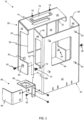
- a mounting bracket assembly 10 according to the present teachings is shown in a disassembled or detached state.
- the bracket assembly 10 When assembled, the bracket assembly 10 is designed to securely fix a display monitor 12 to a supporting structure 14 ( FIGS. 2-4 ).
- the bracket assembly 10 provides for the monitor 12 to be releasably attached to the supporting structure 14, so that the monitor 12 can be easily attached and detached from the supporting structure 14 by a single person.
- the bracket assembly does not require two or more people to install and mount the display monitor to the supporting structure.
- the display monitor 12 may comprise a television (TV) set, a computer monitor, a touchscreen, tablet, or the like.
- the supporting structure 14 may be a wall, a ceiling, or a mounting device that is directly or indirectly fixed to a wall, floor, or ceiling.
- the bracket assembly is mountable to a mounting device in the form of a boom arm.
- the mounting device can be stationary or be moved or articulated into different positions and/or orientations.
- the bracket assembly is adapted to mount to a spine of a TV stand or monitor stand.
- the bracket assembly 10 comprises two main components, a front panel 20 and a rear panel 40, which detachably connect to one another.
- the front panel and the rear panel securely mate with each other to form a housing 16 ( FIG. 3 ) in between the panels.
- the housing 16 is adapted to receive and retain an electronic component 18, as shown in FIGS. 4 , 5A, and 5B .
- Examples of an electronic component 18 include decoders and/or encoders, image processing units, camera control units, or other peripheral devices or accessories that are associated and used with the display monitor 12, especially within the context of a healthcare environment (e.g., medical room, surgical observation room, operating theater).
- the electronic component is a 10G decoder.
- the housing 16 may be adapted to retain other electronic devices, such as but not limited to, a HD box(es), a video network reception box(es), a cable TV satellite box(es), and wired or wireless internet reception device(s).
- the bracket assembly 10 is configured to accommodate different size electronic components within the housing 16.
- the housing formed between the front panel and the rear panel can simultaneously retain multiple electronic devices.
- Both panels are rigid or substantially rigid in order to support the weight of the display monitor 12, with or without the electronic device 18 inserted within the housing 16.
- the front panel 20 and the rear panel 40 may be constructed from one or more metals, or from a composite material.
- the bracket assembly 10 in general may be formed by any one or more manufacturing processes, including but not limited to, casting, moulding, metal forming, machining, welding, and additive manufacturing.
- the front panel 20 includes a front plate 22, and the rear panel 40 includes a back plate 42.
- the front and rear plates have the shape of a rectangle. Nevertheless, the plates may comprise other shapes.
- the front plate 22 is configured to mount to the display monitor 12, while the back plate 42 is configured to mount to the supporting structure 14, as shown in FIG. 2 .
- a plurality of mounting holes 30 are formed through the front plate 22, each hole being adapted to receive a fastener such as a screw, bolt, or the like, to secure the front plate to the display monitor.
- the mounting holes 30 are arranged according to VESA mounting interface standard. This provides for universal mounting of the front panel 20 to all display monitors. In other embodiments, the mounting holes 30 may not be arranged according to VESA standard, but instead may utilize a unique mounting pattern that is specifically designed to match a mounting pattern on the display monitor.
- the back plate includes a plurality of mounting fixtures 50, each being adapted to secure the back plate to the support structure 14.
- FIG. 1 depicts each mounting fixture 50 as a cylindrical protrusion which projects in a rearward direction from an exterior surface of the back plate 42.
- a hole is formed in the mounting fixture and extends from one end along the central axis of the fixture, wherein the hole receives a fastener such as a screw, bolt, or the like.
- the mounting fixtures 50 are arranged according to VESA mounting interface standard. This provides for universal mounting of the rear panel 40 to all supporting structure.
- the mounting fixtures 50 may not be arranged according to VESA standard, but instead may utilize a unique mounting pattern that is specifically designed to match a mounting pattern on the support structure.
- the front plate 22 may be integrated with the display monitor 12, and/or the back plate 42 may be integrated with the supporting structure 14. As such, the mounting holes 30, mounting fixtures 50, and corresponding fasteners may not be required.
- the front panel 20 comprises at least one extension 28 disposed along one side of the front plate 22.
- the front plate extension 28 may be a support flange or the like, which projects in a rearward direction out from the front plate.
- the front plate extension 28 is disposed along an upper edge of the front plate 22, extending between opposing sides of the front plate.
- the upper edge of the front plate is illustrated in FIGS. 1-4 being substantially horizontal.
- the extension 28 continues for the entire width of the front plate, wherein a first end of the extension is situated at one of the opposing sides and a second end of the extension is situated at the other opposing side.
- the front plate extension 28 extends only a portion of the width of the front plate, while in other embodiments, the front plate extension 28 extends beyond the width of the front plate and as such protrudes beyond the borders of the front plate defined by the opposing sides.
- the rear panel 40 comprises at least one extension 44, 46 disposed along at least one side of the rear plate 42.
- the at least one back plate extension projects in a forward direction out from the back plate.
- the front plate extension 28 overlaps in a contact area or surface 60 with the back plate extension to transfer a weight of the monitor 12 to the support structure 14 and to at least partially enclose a volume defining the housing 16 for retaining the electronic component 18 between the display monitor and the support structure.
- the rear panel 40 comprises two extensions 44, 46 disposed along opposing vertical sides of the back plate 42, as shown in FIG. 1 . With two back plate extensions, the rear panel 40 more completely encloses the volume defining the electronic component housing 16.
- Both back plate extensions project in a forward direction out from the back plate, and preferably, are parallel to one another.
- the back plate extensions may not be parallel with each other, but instead may be angled towards each other or away from each.
- the front plate extension 28 overlaps in a contact area or surface 60 which is formed between an edge surface 48 of each back plate extension and the under surface 32 of the front plate extension, wherein the under surface lays on top of the edge surfaces.
- the back plate extensions are in the form of flanges or the like.
- the back plate extensions 44, 46 and/or the edge surfaces 48 may be angled slightly in an upward direction as the back plate extension projects in the forward direction.
- FIG. 1 shows in particular the edge surfaces 48 of the two back plate extensions 44, 46 defining a planar surface that is angled in an upward direction from an upper edge of the back plate 42.
- the angle ⁇ between the back plate and the edge surfaces 48 may be within a range from 90° to 150°, or from 90° to 135°, or from 90° to 120°.
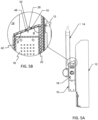
- FIG. 5B which is cross sectional view of a side of the bracket assembly, clearly shows the angle ⁇ .
- the front plate extension 28 and/or the under surface 32 may be angled slightly in a downward direction to more securely hold the display monitor to the supporting structure and thus further maintain the weight of the display monitor on the supporting structure.
- the under surface 32 of the front plate extension 28 defines a planar surface that is angled in a downward direction from the upper edge of the front plate 22.
- the angle ⁇ between the front plate and the under surface 32 is an acute angle.
- the angle ⁇ may be within a range from 30° to 90°, or from 45° to 90°, or from 60° to 90° ( FIG. 5B ).
- the angles ⁇ and ⁇ are supplementary angles or angles whose degree measures add up to or around 180°.
- the back plate extensions 44, 46 and/or the edge surfaces 48 may be oriented perpendicular or substantially 90° to the back plate. That is, the angle ⁇ between the back plate and the edge surfaces 48 is substantially 90°.
- the front plate extension 28 and/or the under surface 32 may also be oriented perpendicular or substantially 90° to the front plate. In this configuration, the front plate extension and the back plate extensions mate with one another, wherein the under surface 32 and the edge surfaces 48 are parallel or substantially parallel.
- the back plate 42 may have a back plate extension disposed along an upper edge of the back plate, wherein the upper edge is substantially horizontal.
- the back plate extension may extend only a portion of the width of the back plate, the entire width of the back plate, or beyond the width of the back plate such that the back plate extension protrudes beyond the opposing sides of the back plate.
- the contact area or surface 60 between the front panel and the rear panel is thereby formed between an over surface (upper surface) of the back plate extension and an under surface 32 (lower surface) of the front plate extension 28, wherein the under surface lays on top of the over surface.
- the back plate extension and/or the over surface may be angled slightly in an upward direction as the back plate extension projects in the forward direction.
- the back plate extension and/or the over surface is oriented perpendicular to the back plate.
- the angle between the back plate and the back plate extension and/or the over surface should preferably be supplementary to the angle ⁇ formed between the front plate and the front plate extension 28 and/or under surface 32, i.e., the total of the degree measures added together should be substantially 180°.
- the front plate extension and the back plate extensions mate with one another, wherein the under surface 32 and the over surface are parallel or substantially parallel.
- the rear panel 40 may also include one or more of the back plate extensions 44, 46 discussed above.
- FIG. 1 shows that the front panel 20 may comprise two more front plate extensions 24, 26 projecting in a rearward direction from opposing vertical edges of the front plate 22.
- the front plate extensions 24, 26 help to more completely enclose the volume defining the electronic component housing 16 as well as to position the front plate on the back plate.
- the extensions 24, 26 can be in the form of side flanges or the like.
- the front plate extension 28 (support flange) is positioned between the side flanges 24, 26. In some embodiments, the ends of the front plate extension 28 are connected to the side flanges.
- Each side flange extends the entire length of the front plate 22. Alternatively, one or both of the side flanges may extend only a portion of the length of the front plate 22.
- the side flanges 24, 26 are oriented to be substantially perpendicular to the front plate and parallel to one another, as shown in FIG. 1 . Conversely, the side flanges 24, 26 may not be parallel with each other, but instead may be angled towards each other or away from each other.
- FIG. 3 illustrates when the bracket assembly is assembled.
- the front panel 20 is releasably attached to the rear panel 40 by positioning the front plate extension 28 over the back plate extension(s) 44, 46. More specifically, in a contact area or surface 60, the under surface 32 of the front plate extension 28 overlaps the edge surfaces 48 and/or over surface of the back plate extensions.
- the back plate extensions 44 and 46 also mate with the two more front plate extensions 24 and 26 when the bracket assembly is in the assembled state. For example, an inner surface of the front plate extension 24 overlaps an outer surface of the back plate extension 44, while an inner surface of the front plate extension 26 overlaps an outer surface of the back plate extension 46.
- the back plate extensions 44, 46 are similarly perpendicular to the back plate 42 and parallel to one another.
- the front plate extensions 24, 26 are configured so that they angle towards each other as they project away from the front plate, the back plate extensions 44, 46 angle away from each other as they project from the back plate, or vice versa. This enables the front plate extensions to still mate with the back plate extensions. Further, this minimizes gaps or open spaces within the housing 16 that are not used or occupied by the electronic component when retained within the housing.
- the front panel and the rear panel are each dimensioned so that when the electronic component is inside the housing, there are minimal to no gaps or opens spaces in which dust or other contaminants may collect.
- the length of the rear panel is greater than the length of the front panel. This means that the bottom end of the rear panel 40 extends further below than the bottom end of the front panel 20 when the bracket assembly is assembled.
- the extra length of the rear panel provides for a cable fixture 80 to be positioned on at least one of the back plate extensions 44, 46.
- the bracket assembly includes at least one locking mechanism 62.
- FIG. 1 specifically show an embodiment where the bracket assembly has two locking mechanisms 62.
- a screw, bolt, pin, or the like may serve as the locking mechanism 62.
- At least one key hole 64 is formed completely through one of or both of the front plate extensions 24, 26.
- One or more of the back plate extensions also has a key hole 66.
- the key hole 64 aligns with the key hole 66 when the front plate and back plate are releasably attached. With the key holes in alignment, the locking mechanism(s) 62 can be inserted therein. Accordingly, in order to detach the front panel from the rear panel, the locking mechanism 62 would have to be removed first.
- the front panel can be secured to the rear panel without the locking mechanism(s) 62 and key holes 64, 66 present in the bracket assembly. That is, the absence of the locking mechanism(s) 62 and key holes 64, 66 does not detract from the purpose of and the benefits imparted by the present teachings.
- the electronic component housing 16 is formed between the front plate 22, the front plate extensions 24, 26, 28, the back plate 42, and the back plate extensions 44, 46. Accordingly, the housing 16 is at least partially closed on six sides.
- the front and back plates are designed so that no extensions are present along their respective bottom edges.
- the housing is therefore open on a bottom side to provide for insertion and removal of the electronic device 18 into and out of the housing 16, as shown in FIGS. 3-4 .
- the electronic component 18 can be easily inserted into the housing 16 with or without the display monitor being connected to the front panel 20.
- the bracket assembly comprises one or more fastening mechanisms 70 to secure the electronic component 18 within the housing 16.
- the fastening mechanism 70 may be a screw, bolt, pin, or the like.
- a through hole 72 is formed in one or both of the rear plate extensions 44, 46 and configured to receive the fastening mechanism(s) 70.
- the fastening mechanism 70 is inserted into the through hole 72, it is then feed into a mounting hole in the electronic component 18.
- the fastening mechanism 70 would first have to be removed.
- the electronic component 18 is pressure fitted within the housing 16 such that the fastening mechanism(s) 70 and through hole(s) 72 are not necessary to secure the electronic component 18 to the bracket assembly.
- the front and rear panels 20, 40 are designed to allow ventilation for the electronic component 18.
- at least one of the back plate extensions 44, 46 has an aperture 52 therethrough.
- At least one of the front plate extensions 24, 26 has a cutout 34. As shown in FIG. 1 , the cutout 34 is formed starting at a free end of the front plate extension and stretching in a direction towards the front plate 22.
- the cutout 34 aligns with the aperture 52 to provide a ventilation opening into the housing 16, thereby providing air flow into and out of the housing.
- both back plate extensions 44, 46 have an aperture 52
- both front plate extensions 24, 26 have a cutout 34. This increases the amount of air flow into and out of the housing, and as such, prevents overheating of the electronic component when it is retained within the housing.
- a portion of the front plate 22 is removed in order to form an opening 36. This helps to reduce the weight of the front panel 20.
- the opening 36 can provide additional ventilation for the electronic component 18.
- the opening 36 allows for a section of the display monitor 12 to be visible during installation. In some instances, the section of the display monitor made visible by the opening 36 may comprise inputs and outputs, which provide electrical connection (e.g., data, power) between the display monitor 12 and the electronic component 18.
- a portion of the rear plate 42 is removed in order to form an opening 54, which helps to reduce the weight of the rear panel 40.
- the opening 54 can provide additional ventilation for the electronic component 18.
- the front plate extension 28 includes an orifice 74, which provides access to the interior of the electronic component housing 16 and to the electronic device 18 when it is retained within the housing.
- the orifice 74 allows a user to manipulate the electronic component or engage buttons or controls on the electronic component while it is disposed within the housing.
- the bracket assembly 10 also comprises an access panel 76 which releasably attaches to the front plate extension 28 via a plurality of fasteners 78 in order to cover the orifice 74.
- the access panel 76 helps to cover the electronic component when access thereto is not necessary. This helps to reduce dust or other contaminants from entering and settling within the housing 16.
- the bracket assembly also comprises a cable fixture 80 attached to one of the back plate extensions 44, 46 via a plurality of fasteners 82.
- the cable fixture 80 is formed by two L-shaped plates 84, 86 that are connected to one another.
- the cable fixture 80 also includes one or more communications connections or connectors 88 arranged between the L-shaped plates 84 and 86.
- Any type of data communication connector(s) such as, but not limited to, USB, coax, Ethernet, and XLR, provides electrical connection between the electronic device and the display monitor and/or between the electronic device and some other external system or device have cables feed through or along the supporting structure (e.g., boom arm).
- the present teachings also provide for a method of mounting an electrical equipment 18 in between a display monitor 12 and a supporting structure 14 using the bracket assembly 10.
- Such method requires only one person to complete, but allows for multiple people to participate in the process.
- the method comprises: mounting the front panel 20 to the display monitor 12 by inserting fasteners through the mounting holes 30 and fixing them into the display monitor 12; and mounting the rear panel 40 to the support structure 14 by inserting another set of fasteners through mounting holes present in the support structure and then fixing them into the mounting fixtures 50 ( FIG. 2 ).
- the method further comprises: lifting the display monitor with the front panel attached thereto to a height so that the front plate extension 28 is above or clears the rear panel; positioning the front panel to be aligned with the rear panel; and then placing the front panel over the rear panel so that the front plate extension overlaps in a contact area or surface 60 with the back plate extension ( FIG. 3 ).
- the step of positioning the front panel relative to the rear panel includes: aligning the front plate extensions 24, 26 in relation to the back plate extensions 44, 46.
- the front plate extensions should be arranged so that the back plate extensions can be inserted in between the front plate extensions in a mating manner.
- the method may optionally include locking the front panel to the rear panel.
- the method further comprises the steps of: inserting an electronic component 18 into the housing 16 from the bottom of the housing and securing the electronic component within the housing ( FIGS. 3-4 ).
- the step of securing the electronic component may comprise using a fastening mechanism 70, wherein the fastening mechanism 70 is feed through a through hole 72 and fixed into a recess within the electronic component.
- the step of securing may simply comprise establishing a pressure fitted contact between the electronic component and the rear and front panels of the bracket assembly.
- the method also comprises the step of connecting the electronic component to the display monitor via the cable fixture 80.
- the display monitor need not be detached from the support structure. Instead, the electronic component may simply be withdrawn through the bottom of the housing if there is no fastening mechanism 70, and if a fastening mechanism is present, then an initial step of removing the fastening mechanism 70 is required.
- the display monitor 12 can be detached from the support structure 14 without removing the electronic component 18 from within the housing 16 and without disassembling the bracket assembly 10. Specifically, the fasteners connecting the rear panel to the support structure at the mounting fixtures 50 can simply be removed. When this is done, the display monitor, bracket assembly, and electronic component (if present) are detached collectively.
- bracket assembly is possible.
- layout of the panels of the bracket assembly may differ from those shown in the Figures without departing from the scope and spirit of the present teachings.
- the particular components included in the bracket assembly and/or arrangement of components in the bracket assembly may differ from that shown in the Figures without departing from the scope and spirit of the present teachings.
Landscapes
- Engineering & Computer Science (AREA)
- General Engineering & Computer Science (AREA)
- Mechanical Engineering (AREA)
- Microelectronics & Electronic Packaging (AREA)
- Devices For Indicating Variable Information By Combining Individual Elements (AREA)
Claims (15)
- Halterungsanordnung (10) zur Befestigung eines Anzeigemonitors (12) an einer Trägerstruktur (14), mit:einer Rückplatte (42), die konfiguriert ist, um an der Trägerstruktur (14) befestigt zu werden;einer Rückplattenerweiterung (44, 46), die entlang einer Seite der Rückplatte (42) angeordnet ist;einer Frontplatte (22), die konfiguriert ist, um an dem Anzeigemonitor (12) befestigt zu werden;einer Frontplattenerweiterung (28), die entlang einer Seite der Frontplatte (22) angeordnet ist;einer Kontaktfläche (60) gebildet durch die Frontplattenerweiterung (28), die die Rückplattenerweiterung (44, 46) überlappt, wobei die Kontaktfläche (60) ein Gewicht des Monitors (12) auf die Trägerstruktur (14) überträgt, wobei die Rückplattenerweiterung (44, 46) in ihrem Abstehen von der Rückplatte (42) in einer Aufwärtsrichtung geneigt ist, und die Frontplattenerweiterung (28) in ihrem Abstehen von der Frontplatte (22) in einer Abwärtsrichtung geneigt ist; undeinem Volumen, das zumindest teilweise von der Frontplatte (22), der Rückplatte (42) und den Erweiterungen (28, 44, 46) umgeben ist, um eine elektronische Vorrichtung (18) zwischen dem Anzeigemonitor (12) und der Trägerstruktur (14) aufzunehmen,dadurch gekennzeichnet, dass die Halterungsanordnung (10) ferner eine weitere Rückplattenerweiterung (44, 46) umfasst, wobei die Kontaktfläche (60) zwischen einer Kantenfläche (48) jeder Rückplattenerweiterung (44, 46) und einer unteren Oberfläche (32) der Frontplattenerweiterung (26) gebildet ist, und wobei die beiden Rückplattenerweiterungen (44, 46) an gegenüberliegenden Seiten der Rückplatte (42) liegen.
- Halterungsanordnung (10) gemäß Anspruch 1, bei der die Kontaktfläche (60) zwischen einer oberen Oberfläche der Rückplattenerweiterung und einer unteren Oberfläche der Frontplattenerweiterung (28) gebildet wird und/oder die Kontaktfläche (60) zwischen einer Randfläche (48) der Rückplattenerweiterung (44, 46) und der unteren Oberfläche (32) der Frontplattenerweiterung (28) gebildet wird..
- Halterungsanordnung (10) gemäß Anspruch 2, bei der die Kantenfläche (48) der Rückplattenerweiterung (44, 46) in der Aufwärtsrichtung geneigt ist, um den Anzeigemonitor (12) sicherer zu halten, und bei der ein Winkel zwischen der Rückplatte (42) und der Kantenfläche (48) zwischen 90° und 150° beträgt.
- Halterungsanordnung (10) gemäß einem der vorangehenden Ansprüche, wobei die Frontplattenerweiterung (28) sich an einem oberen Rand der Frontplatte (22) befindet.
- Halterungsanordnung (10) gemäß Anspruch 1, bei der die untere Oberfläche (32) der Frontplattenerweiterung (28) in der Abwärtsrichtung geneigt ist, und bei der ein Winkel zwischen der Frontplatte (22) und der unteren Oberfläche (32) zwischen 30° und 90° beträgt.
- Halterungsanordnung (10) gemäß einem der vorangegangenen Ansprüche, wobei die Halterungsanordnung (10) zwei weitere Frontplattenerweiterungen (24, 26) aufweist, die an gegenüberliegenden Seiten der Frontplatte (22) angeordnet sind, um die Frontplatte (22) an der Rückplatte (42) zu positionieren, wobei das Volumen ferner von den zwei weiteren Frontplattenerweiterungen (24, 26) umgeben ist.
- Halterungsanordnung (10) gemäß Anspruch 6, wobei die Halterungsanordnung (10) ferner umfasst:einen Ausschnitt (34), der in mindestens einer der beiden weiteren Frontplattenerweiterungen (24, 26) ausgebildet ist;eine Öffnung (52), die in mindestens einer der Rückplattenerweiterungen (44, 46) ausgebildet ist;wobei die Öffnung (52) mit dem Ausschnitt (34) fluchtet, um eine Belüftungsöffnung zum Bereitstellen eines Luftstroms in und aus dem Volumen bereitzustellen, wenn die Frontplatte (22) mit der Rückplatte (42) verbunden ist.
- Halterungsanordnung (10) gemäß einem der vorangegangenen Ansprüche, bei der die Rückplattenerweiterung (44, 46) eine Befestigung (70) zum Sichern des elektronischen Geräts (18) innerhalb des Volumens aufweist.
- Halterungsanordnung (10) gemäß einem der vorangegangenen Ansprüche, bei der das Volumen an einer Unterseite offen ist, um das Einsetzen und Entfernen der elektronischen Vorrichtung (18) in das Volumen und aus diesem heraus zu ermöglichen.
- Halterungsanordnung (10) gemäß einem der vorangehenden Ansprüche, wobei die Halterungsanordnung (10) ferner eine Kabelbefestigung (80) umfasst, die an der Rückplattenerweiterung (44) angebracht ist, wobei die Kabelbefestigung (80) eine elektrische Verbindung zwischen dem elektronischen Gerät (18) und dem Anzeigemonitor (12) herstellt.
- Halterungsanordnung (10) gemäß einem der vorangehenden Ansprüche, bei der:die Rückplatte (42) eine Vielzahl von Befestigungsvorrichtungen (50) aufweist, die gemäß dem VESA-Standard zur Aufnahme von Befestigern angeordnet sind, um die Rückplatte an der Trägerstruktur (14) zu befestigen; unddie Frontplatte (22) eine Vielzahl von Befestigungslöchern (30) aufweist, die gemäß dem VESA-Standard zur Aufnahme von Befestigern angeordnet sind, um die Frontplatte (22) an dem Anzeigemonitor (12) zu befestigen.
- Halterungsanordnung (10) gemäß Anspruch 6, wobei die Halterungsanordnung (10) mindestens eine Verriegelung (62) umfasst, die die Frontplatte (22) gegen ein Entfernen von der Rückplatte (42) sichert, indem sie die Bewegung der Frontplattenerweiterung (24, 26, 28) weg von den Rückplattenerweiterungen (42, 44) einschränkt.
- Halterungsanordnung (10) gemäß Anspruch 12, bei der:mindestens eine der Rückplattenerweiterungen (44, 46) ein erstes Schlüsselloch (66) aufweist;mindestens eine der zwei weiteren Frontplattenerweiterungen (24, 26) ein zweites Schlüsselloch (64) aufweist, das mit dem ersten Schlüsselloch (66) fluchtet, wenn die Platten (22, 42) verbunden sind; unddie Verriegelung (62) ein Befestiger ist, der in die Schlüssellöcher (64, 66) einführbar ist.
- Verfahren zum Befestigen eines Anzeigemonitors (12) an einer Trägerstruktur (14), umfassend:Verbinden eines Frontpaneels (20) einer Halterungsanordnung (10) mit einem Anzeigemonitor (12), wobei das Frontpaneel (20) eine Frontplatte (22) und eine Frontplattenerweiterung (28) aufweist, die entlang einer Seite der Frontplatte (22) angeordnet ist, wobei die Frontplattenerweiterung (28) in ihrem Abstehen von der Frontplatte (22) in einer Abwärtsrichtung geneigt ist;Verbinden eines Rückpaneels (40) der Halterungsanordnung (10) mit einer Trägerstruktur (14), wobei das Rückpaneel (40) eine Rückplatte (42) und eine Rückplattenerweiterung (44) und eine weitere Rückplattenerweiterung (46) entlang gegenüberliegender Seiten der Rückplatte (42) aufweist, wobei die Oberseiten (48) der Rückplattenerweiterungen (44, 46) in ihrem Abstehen von der Rückplatte (42) in einer Aufwärtsrichtung geneigt sind;Anheben des Anzeigemonitors (12) mit dem daran befestigten Frontpaneel (20) auf eine Höhe, so dass die Frontplattenerweiterung (28) über der Rückplattenerweiterung (44, 46) ist;Befestigen des Anzeigemonitors (12) an der Trägerstruktur durch Überlappen der Oberseiten (48) der Rückplattenerweiterungen (44, 46) mit der Frontplattenerweiterung (28), um einen Kontaktbereich (60) zu bilden, wobei der Kontaktbereich (60) ein Gewicht des Monitors (12) auf die Trägerstruktur (14) überträgt;wobei ein Volumen zumindest teilweise von der Frontplatte (22), der Rückplatte (42) und den Erweiterungen (24, 26, 28, 44, 46) umgeben ist, um eine elektronische Vorrichtung (18) zwischen dem Anzeigemonitor (12) und der Trägerstruktur (14) aufzunehmen.
- Verfahren gemäß Anspruch 14, bei dem:das Volumen an einer Unterseite offen ist; unddas Verfahren das Einführen der elektronischen Vorrichtung (18) von unterhalb der Halterungsanordnung (10) und durch die Unterseite hindurch und das Befestigen der elektronischen Vorrichtung (18) in dem Volumen umfasst.
Applications Claiming Priority (1)
| Application Number | Priority Date | Filing Date | Title |
|---|---|---|---|
| US16/367,926 US11415264B2 (en) | 2019-03-28 | 2019-03-28 | Bracket assembly and method for mounting electrical equipment in between a monitor and a supporting structure |
Publications (2)
| Publication Number | Publication Date |
|---|---|
| EP3715697A1 EP3715697A1 (de) | 2020-09-30 |
| EP3715697B1 true EP3715697B1 (de) | 2023-08-30 |
Family
ID=70058107
Family Applications (1)
| Application Number | Title | Priority Date | Filing Date |
|---|---|---|---|
| EP20166529.6A Active EP3715697B1 (de) | 2019-03-28 | 2020-03-28 | Halterungsanordnung und verfahren zur montage von elektrischer ausrüstung zwischen einem monitor und einer tragenden struktur |
Country Status (2)
| Country | Link |
|---|---|
| US (1) | US11415264B2 (de) |
| EP (1) | EP3715697B1 (de) |
Families Citing this family (9)
| Publication number | Priority date | Publication date | Assignee | Title |
|---|---|---|---|---|
| US11415264B2 (en) * | 2019-03-28 | 2022-08-16 | Karl Storz Endoscopy-America, Inc. | Bracket assembly and method for mounting electrical equipment in between a monitor and a supporting structure |
| TWI715465B (zh) * | 2020-03-17 | 2021-01-01 | 技嘉科技股份有限公司 | 壁掛組合 |
| CN112293982A (zh) * | 2020-10-28 | 2021-02-02 | 上海微竺实业有限公司 | 一种多功能家用电视机放置柜 |
| CN114590209A (zh) * | 2020-12-07 | 2022-06-07 | 株式会社本田阿克塞斯 | 车辆用监视装置 |
| US11934234B2 (en) | 2022-01-10 | 2024-03-19 | Craft O Graph LLC | Computer chassis |
| US20240180661A1 (en) * | 2022-12-01 | 2024-06-06 | Boston Scientific Scimed, Inc. | Mounting enclosure for use with a medical cart |
| US12546432B2 (en) * | 2022-12-01 | 2026-02-10 | Boston Scientific Scimed, Inc. | Mounting system for mounting a medical computer to a hospital boom assembly |
| US12598718B2 (en) * | 2023-03-27 | 2026-04-07 | Toyota Motor Engineering & Manufacturing North America, Inc. | Analog converter box mounting structure |
| US12102231B1 (en) * | 2024-01-04 | 2024-10-01 | Shelton Specialties, Llc | Stabilizer bracket for electronic device |
Citations (1)
| Publication number | Priority date | Publication date | Assignee | Title |
|---|---|---|---|---|
| US20090052128A1 (en) * | 2007-08-23 | 2009-02-26 | Song San Yeh | Mounting frame structure for flat panel display device |
Family Cites Families (38)
| Publication number | Priority date | Publication date | Assignee | Title |
|---|---|---|---|---|
| US3636669A (en) * | 1970-01-12 | 1972-01-25 | James R Attkisson | Panel systems |
| US4712761A (en) * | 1987-01-29 | 1987-12-15 | Wassell Edward T | Picture wall hanging assembly |
| US6400560B1 (en) * | 2000-11-08 | 2002-06-04 | Yue-Hui Chian | Engaging device for a computer screen in a car |
| US6935883B2 (en) * | 2002-04-24 | 2005-08-30 | Innovative Office Products, Inc. | Quick interconnection system for electronic devices |
| US6953895B2 (en) * | 2002-09-26 | 2005-10-11 | Terk Technologies Corporation | Electronics housings and associated connectors for cable/wiring distribution system |
| US20050082453A1 (en) * | 2003-10-20 | 2005-04-21 | Aaeon Technology Inc. | Mechanism for mounting LCD TV on wall |
| USD531488S1 (en) * | 2004-08-27 | 2006-11-07 | Hangman Products, Inc. | Wall mount hanger |
| USD542631S1 (en) * | 2005-03-08 | 2007-05-15 | Hangman Products, Inc. | Wall hanger |
| US7918426B2 (en) * | 2005-08-18 | 2011-04-05 | Avf Group Limited | Adjustable mount |
| GB0516913D0 (en) * | 2005-08-18 | 2005-09-28 | Avf Group Ltd | Tilting mechanism |
| US20070170336A1 (en) * | 2006-01-25 | 2007-07-26 | Chin-Chu Li | Hanging support apparatus |
| USD560222S1 (en) * | 2006-07-28 | 2008-01-22 | Omnimount Systems, Inc. | Tiltable plate mount for audio/visual equipment |
| USD561188S1 (en) * | 2006-10-31 | 2008-02-05 | Csav, Inc. | Tilt adjustable display mount |
| USD560676S1 (en) * | 2006-10-31 | 2008-01-29 | Csav, Inc. | Tilt adjustable display mount |
| US7719832B2 (en) * | 2006-10-31 | 2010-05-18 | Hewlett-Packard Development Company, L.P. | Computing device mounting system |
| USD574815S1 (en) * | 2006-12-28 | 2008-08-12 | Bell'o International Corp. | Fixed flat panel display mount |
| USD561749S1 (en) * | 2006-12-28 | 2008-02-12 | Bell'o International Corp. | Mounting plate for flat panel displays |
| WO2008085422A2 (en) * | 2006-12-28 | 2008-07-17 | Bell'o International Corp. | Flat panel display mounting system |
| USD587714S1 (en) * | 2006-12-28 | 2009-03-03 | Bell'o International Corp. | Tiltable flat panel display mount |
| US20080186669A1 (en) * | 2007-02-02 | 2008-08-07 | Clientron Corp. | Computer case fixing structure |
| JP4801774B2 (ja) * | 2007-03-30 | 2011-10-26 | パイオニア株式会社 | 機器用パネル |
| JP5041365B2 (ja) * | 2007-11-28 | 2012-10-03 | 日本電気株式会社 | 屋外通信装置の設置構造及び設置方法 |
| TWI396960B (zh) * | 2008-06-03 | 2013-05-21 | Aopen Inc | Backstop module |
| TW201026048A (en) * | 2008-12-17 | 2010-07-01 | Coretronic Display Solution Corp | External holder of display |
| CN101930257A (zh) * | 2009-06-18 | 2010-12-29 | 鸿富锦精密工业(深圳)有限公司 | 支架及带有该支架的显示器和电脑系统 |
| TWM391804U (en) * | 2010-05-31 | 2010-11-01 | Aopen Inc | Fixed rack module and electronic device assembly |
| CN102695385A (zh) * | 2011-03-25 | 2012-09-26 | 鸿富锦精密工业(深圳)有限公司 | 电子装置 |
| US20130048812A1 (en) * | 2011-08-25 | 2013-02-28 | Anthony Lozano | Flat panel mounting system |
| US9408465B2 (en) | 2011-09-15 | 2016-08-09 | Innovative Americans, LLC | Method and device for wall mounting flat panel monitor and storing associated audio/video components |
| US8991062B2 (en) * | 2011-12-15 | 2015-03-31 | Atkinson Audio Inc. | Locating and relocating device |
| TWI501070B (zh) * | 2012-06-05 | 2015-09-21 | Aopen Inc | 懸掛裝置 |
| TWI524771B (zh) * | 2012-08-14 | 2016-03-01 | 建碁股份有限公司 | 顯示器支撐模組 |
| US20170211743A1 (en) * | 2016-01-22 | 2017-07-27 | Averry Shane YANYK | Rear-Mounted Electronic Display Component Holder |
| US10126787B1 (en) * | 2017-09-19 | 2018-11-13 | Hewlett-Packard Development Company, L.P. | Computing device mounting enclosures |
| JP7073087B2 (ja) * | 2017-12-18 | 2022-05-23 | Dynabook株式会社 | ホルダ |
| DE102018101210B4 (de) * | 2018-01-19 | 2019-08-22 | Fujitsu Client Computing Limited | Wandbefestigung für eine elektronische Anzeige, Computeranordnung und Verfahren zur Montage einer elektronischen Anzeige und eines Computersystems an einer Wand |
| US10876325B2 (en) * | 2018-06-12 | 2020-12-29 | Steven Wai-Tong Cheung | Mounting device for electronic equipment |
| US11415264B2 (en) * | 2019-03-28 | 2022-08-16 | Karl Storz Endoscopy-America, Inc. | Bracket assembly and method for mounting electrical equipment in between a monitor and a supporting structure |
-
2019
- 2019-03-28 US US16/367,926 patent/US11415264B2/en active Active
-
2020
- 2020-03-28 EP EP20166529.6A patent/EP3715697B1/de active Active
Patent Citations (1)
| Publication number | Priority date | Publication date | Assignee | Title |
|---|---|---|---|---|
| US20090052128A1 (en) * | 2007-08-23 | 2009-02-26 | Song San Yeh | Mounting frame structure for flat panel display device |
Also Published As
| Publication number | Publication date |
|---|---|
| US11415264B2 (en) | 2022-08-16 |
| US20200315042A1 (en) | 2020-10-01 |
| EP3715697A1 (de) | 2020-09-30 |
Similar Documents
| Publication | Publication Date | Title |
|---|---|---|
| US11415264B2 (en) | Bracket assembly and method for mounting electrical equipment in between a monitor and a supporting structure | |
| US7516924B2 (en) | Articulated boom for positioning video and medical equipment in hospital operating rooms | |
| US7726617B2 (en) | Flat panel display mounting system | |
| US8966765B2 (en) | Medical boom with articulated arms and a base with preconfigured removable modular racks used for storing electronic and utility equipment | |
| US7696872B2 (en) | Rack mounted access/security control panel | |
| CN102282735B (zh) | 用于网络装置的附加装置 | |
| US20070176060A1 (en) | Medical boom with articulated arms and a base with preconfigured removable modular racks used for storing electronic and utility equipment | |
| US6918562B2 (en) | Device for combining electronic appliances and displaying apparatuses employing the same | |
| US6927983B1 (en) | Electronic equipment module apparatus and method | |
| CN102282734B (zh) | 用于网络装置的安全系统 | |
| CA2447297A1 (en) | A cabinet for mounting electronic equipment | |
| TWI554821B (zh) | 監控攝影機安裝座及其安裝方法 | |
| US20190376320A1 (en) | Mounting device for electronic equipment | |
| US8418974B2 (en) | Mounting assembly for rack equipment | |
| EP2751606B1 (de) | Apparat und verfahren zur werkzeuglosen, lösbaren befestigung von komponenten an einem glasfaserverteilerschrank | |
| WO2008036326A2 (en) | Rack mounted access/security control panel | |
| US7907391B2 (en) | Display device having a detachable base part | |
| EP2028916A2 (de) | Anzeigemodul-Stützstruktur und Flüssigkristallfernsehen | |
| KR20040063652A (ko) | 평판형 영상 디스플레이 기기의 벽체 매립형 벽걸이 장치 | |
| US20230332734A1 (en) | Device compatible mounting stand | |
| US20220143814A1 (en) | Reconfigurable controller base for robotic arm | |
| CN217366808U (zh) | 麻醉设备 | |
| US20030222850A1 (en) | Flat panel display apparatus | |
| US20080165294A1 (en) | Modular in wall display system and method | |
| JPH10126079A (ja) | 筐体取付け部材安全構造 |
Legal Events
| Date | Code | Title | Description |
|---|---|---|---|
| PUAI | Public reference made under article 153(3) epc to a published international application that has entered the european phase |
Free format text: ORIGINAL CODE: 0009012 |
|
| STAA | Information on the status of an ep patent application or granted ep patent |
Free format text: STATUS: THE APPLICATION HAS BEEN PUBLISHED |
|
| AK | Designated contracting states |
Kind code of ref document: A1 Designated state(s): AL AT BE BG CH CY CZ DE DK EE ES FI FR GB GR HR HU IE IS IT LI LT LU LV MC MK MT NL NO PL PT RO RS SE SI SK SM TR |
|
| AX | Request for extension of the european patent |
Extension state: BA ME |
|
| STAA | Information on the status of an ep patent application or granted ep patent |
Free format text: STATUS: REQUEST FOR EXAMINATION WAS MADE |
|
| 17P | Request for examination filed |
Effective date: 20210330 |
|
| RBV | Designated contracting states (corrected) |
Designated state(s): AL AT BE BG CH CY CZ DE DK EE ES FI FR GB GR HR HU IE IS IT LI LT LU LV MC MK MT NL NO PL PT RO RS SE SI SK SM TR |
|
| STAA | Information on the status of an ep patent application or granted ep patent |
Free format text: STATUS: EXAMINATION IS IN PROGRESS |
|
| 17Q | First examination report despatched |
Effective date: 20210730 |
|
| GRAP | Despatch of communication of intention to grant a patent |
Free format text: ORIGINAL CODE: EPIDOSNIGR1 |
|
| STAA | Information on the status of an ep patent application or granted ep patent |
Free format text: STATUS: GRANT OF PATENT IS INTENDED |
|
| INTG | Intention to grant announced |
Effective date: 20230310 |
|
| P01 | Opt-out of the competence of the unified patent court (upc) registered |
Effective date: 20230526 |
|
| GRAS | Grant fee paid |
Free format text: ORIGINAL CODE: EPIDOSNIGR3 |
|
| GRAA | (expected) grant |
Free format text: ORIGINAL CODE: 0009210 |
|
| STAA | Information on the status of an ep patent application or granted ep patent |
Free format text: STATUS: THE PATENT HAS BEEN GRANTED |
|
| RAP1 | Party data changed (applicant data changed or rights of an application transferred) |
Owner name: KARL STORZ SE & CO. KG |
|
| AK | Designated contracting states |
Kind code of ref document: B1 Designated state(s): AL AT BE BG CH CY CZ DE DK EE ES FI FR GB GR HR HU IE IS IT LI LT LU LV MC MK MT NL NO PL PT RO RS SE SI SK SM TR |
|
| REG | Reference to a national code |
Ref country code: GB Ref legal event code: FG4D |
|
| REG | Reference to a national code |
Ref country code: CH Ref legal event code: EP |
|
| REG | Reference to a national code |
Ref country code: DE Ref legal event code: R096 Ref document number: 602020016496 Country of ref document: DE |
|
| REG | Reference to a national code |
Ref country code: IE Ref legal event code: FG4D |
|
| REG | Reference to a national code |
Ref country code: LT Ref legal event code: MG9D |
|
| REG | Reference to a national code |
Ref country code: NL Ref legal event code: MP Effective date: 20230830 |
|
| REG | Reference to a national code |
Ref country code: AT Ref legal event code: MK05 Ref document number: 1605857 Country of ref document: AT Kind code of ref document: T Effective date: 20230830 |
|
| PG25 | Lapsed in a contracting state [announced via postgrant information from national office to epo] |
Ref country code: GR Free format text: LAPSE BECAUSE OF FAILURE TO SUBMIT A TRANSLATION OF THE DESCRIPTION OR TO PAY THE FEE WITHIN THE PRESCRIBED TIME-LIMIT Effective date: 20231201 |
|
| PG25 | Lapsed in a contracting state [announced via postgrant information from national office to epo] |
Ref country code: IS Free format text: LAPSE BECAUSE OF FAILURE TO SUBMIT A TRANSLATION OF THE DESCRIPTION OR TO PAY THE FEE WITHIN THE PRESCRIBED TIME-LIMIT Effective date: 20231230 |
|
| PG25 | Lapsed in a contracting state [announced via postgrant information from national office to epo] |
Ref country code: SE Free format text: LAPSE BECAUSE OF FAILURE TO SUBMIT A TRANSLATION OF THE DESCRIPTION OR TO PAY THE FEE WITHIN THE PRESCRIBED TIME-LIMIT Effective date: 20230830 Ref country code: RS Free format text: LAPSE BECAUSE OF FAILURE TO SUBMIT A TRANSLATION OF THE DESCRIPTION OR TO PAY THE FEE WITHIN THE PRESCRIBED TIME-LIMIT Effective date: 20230830 Ref country code: NO Free format text: LAPSE BECAUSE OF FAILURE TO SUBMIT A TRANSLATION OF THE DESCRIPTION OR TO PAY THE FEE WITHIN THE PRESCRIBED TIME-LIMIT Effective date: 20231130 Ref country code: LV Free format text: LAPSE BECAUSE OF FAILURE TO SUBMIT A TRANSLATION OF THE DESCRIPTION OR TO PAY THE FEE WITHIN THE PRESCRIBED TIME-LIMIT Effective date: 20230830 Ref country code: LT Free format text: LAPSE BECAUSE OF FAILURE TO SUBMIT A TRANSLATION OF THE DESCRIPTION OR TO PAY THE FEE WITHIN THE PRESCRIBED TIME-LIMIT Effective date: 20230830 Ref country code: IS Free format text: LAPSE BECAUSE OF FAILURE TO SUBMIT A TRANSLATION OF THE DESCRIPTION OR TO PAY THE FEE WITHIN THE PRESCRIBED TIME-LIMIT Effective date: 20231230 Ref country code: HR Free format text: LAPSE BECAUSE OF FAILURE TO SUBMIT A TRANSLATION OF THE DESCRIPTION OR TO PAY THE FEE WITHIN THE PRESCRIBED TIME-LIMIT Effective date: 20230830 Ref country code: GR Free format text: LAPSE BECAUSE OF FAILURE TO SUBMIT A TRANSLATION OF THE DESCRIPTION OR TO PAY THE FEE WITHIN THE PRESCRIBED TIME-LIMIT Effective date: 20231201 Ref country code: FI Free format text: LAPSE BECAUSE OF FAILURE TO SUBMIT A TRANSLATION OF THE DESCRIPTION OR TO PAY THE FEE WITHIN THE PRESCRIBED TIME-LIMIT Effective date: 20230830 Ref country code: AT Free format text: LAPSE BECAUSE OF FAILURE TO SUBMIT A TRANSLATION OF THE DESCRIPTION OR TO PAY THE FEE WITHIN THE PRESCRIBED TIME-LIMIT Effective date: 20230830 |
|
| PG25 | Lapsed in a contracting state [announced via postgrant information from national office to epo] |
Ref country code: PL Free format text: LAPSE BECAUSE OF FAILURE TO SUBMIT A TRANSLATION OF THE DESCRIPTION OR TO PAY THE FEE WITHIN THE PRESCRIBED TIME-LIMIT Effective date: 20230830 Ref country code: NL Free format text: LAPSE BECAUSE OF FAILURE TO SUBMIT A TRANSLATION OF THE DESCRIPTION OR TO PAY THE FEE WITHIN THE PRESCRIBED TIME-LIMIT Effective date: 20230830 |
|
| PG25 | Lapsed in a contracting state [announced via postgrant information from national office to epo] |
Ref country code: ES Free format text: LAPSE BECAUSE OF FAILURE TO SUBMIT A TRANSLATION OF THE DESCRIPTION OR TO PAY THE FEE WITHIN THE PRESCRIBED TIME-LIMIT Effective date: 20230830 |
|
| PG25 | Lapsed in a contracting state [announced via postgrant information from national office to epo] |
Ref country code: SM Free format text: LAPSE BECAUSE OF FAILURE TO SUBMIT A TRANSLATION OF THE DESCRIPTION OR TO PAY THE FEE WITHIN THE PRESCRIBED TIME-LIMIT Effective date: 20230830 Ref country code: RO Free format text: LAPSE BECAUSE OF FAILURE TO SUBMIT A TRANSLATION OF THE DESCRIPTION OR TO PAY THE FEE WITHIN THE PRESCRIBED TIME-LIMIT Effective date: 20230830 Ref country code: ES Free format text: LAPSE BECAUSE OF FAILURE TO SUBMIT A TRANSLATION OF THE DESCRIPTION OR TO PAY THE FEE WITHIN THE PRESCRIBED TIME-LIMIT Effective date: 20230830 Ref country code: EE Free format text: LAPSE BECAUSE OF FAILURE TO SUBMIT A TRANSLATION OF THE DESCRIPTION OR TO PAY THE FEE WITHIN THE PRESCRIBED TIME-LIMIT Effective date: 20230830 Ref country code: DK Free format text: LAPSE BECAUSE OF FAILURE TO SUBMIT A TRANSLATION OF THE DESCRIPTION OR TO PAY THE FEE WITHIN THE PRESCRIBED TIME-LIMIT Effective date: 20230830 Ref country code: CZ Free format text: LAPSE BECAUSE OF FAILURE TO SUBMIT A TRANSLATION OF THE DESCRIPTION OR TO PAY THE FEE WITHIN THE PRESCRIBED TIME-LIMIT Effective date: 20230830 Ref country code: PT Free format text: LAPSE BECAUSE OF FAILURE TO SUBMIT A TRANSLATION OF THE DESCRIPTION OR TO PAY THE FEE WITHIN THE PRESCRIBED TIME-LIMIT Effective date: 20240102 Ref country code: SK Free format text: LAPSE BECAUSE OF FAILURE TO SUBMIT A TRANSLATION OF THE DESCRIPTION OR TO PAY THE FEE WITHIN THE PRESCRIBED TIME-LIMIT Effective date: 20230830 |
|
| REG | Reference to a national code |
Ref country code: DE Ref legal event code: R097 Ref document number: 602020016496 Country of ref document: DE |
|
| PLBE | No opposition filed within time limit |
Free format text: ORIGINAL CODE: 0009261 |
|
| STAA | Information on the status of an ep patent application or granted ep patent |
Free format text: STATUS: NO OPPOSITION FILED WITHIN TIME LIMIT |
|
| PG25 | Lapsed in a contracting state [announced via postgrant information from national office to epo] |
Ref country code: SI Free format text: LAPSE BECAUSE OF FAILURE TO SUBMIT A TRANSLATION OF THE DESCRIPTION OR TO PAY THE FEE WITHIN THE PRESCRIBED TIME-LIMIT Effective date: 20230830 |
|
| 26N | No opposition filed |
Effective date: 20240603 |
|
| REG | Reference to a national code |
Ref country code: CH Ref legal event code: PL |
|
| PG25 | Lapsed in a contracting state [announced via postgrant information from national office to epo] |
Ref country code: BG Free format text: LAPSE BECAUSE OF FAILURE TO SUBMIT A TRANSLATION OF THE DESCRIPTION OR TO PAY THE FEE WITHIN THE PRESCRIBED TIME-LIMIT Effective date: 20230830 |
|
| PG25 | Lapsed in a contracting state [announced via postgrant information from national office to epo] |
Ref country code: LU Free format text: LAPSE BECAUSE OF NON-PAYMENT OF DUE FEES Effective date: 20240328 |
|
| PG25 | Lapsed in a contracting state [announced via postgrant information from national office to epo] |
Ref country code: MC Free format text: LAPSE BECAUSE OF FAILURE TO SUBMIT A TRANSLATION OF THE DESCRIPTION OR TO PAY THE FEE WITHIN THE PRESCRIBED TIME-LIMIT Effective date: 20230830 |
|
| PG25 | Lapsed in a contracting state [announced via postgrant information from national office to epo] |
Ref country code: MC Free format text: LAPSE BECAUSE OF FAILURE TO SUBMIT A TRANSLATION OF THE DESCRIPTION OR TO PAY THE FEE WITHIN THE PRESCRIBED TIME-LIMIT Effective date: 20230830 Ref country code: LU Free format text: LAPSE BECAUSE OF NON-PAYMENT OF DUE FEES Effective date: 20240328 Ref country code: BG Free format text: LAPSE BECAUSE OF FAILURE TO SUBMIT A TRANSLATION OF THE DESCRIPTION OR TO PAY THE FEE WITHIN THE PRESCRIBED TIME-LIMIT Effective date: 20230830 |
|
| REG | Reference to a national code |
Ref country code: BE Ref legal event code: MM Effective date: 20240331 |
|
| PG25 | Lapsed in a contracting state [announced via postgrant information from national office to epo] |
Ref country code: BE Free format text: LAPSE BECAUSE OF NON-PAYMENT OF DUE FEES Effective date: 20240331 |
|
| PG25 | Lapsed in a contracting state [announced via postgrant information from national office to epo] |
Ref country code: IE Free format text: LAPSE BECAUSE OF NON-PAYMENT OF DUE FEES Effective date: 20240328 |
|
| PG25 | Lapsed in a contracting state [announced via postgrant information from national office to epo] |
Ref country code: IE Free format text: LAPSE BECAUSE OF NON-PAYMENT OF DUE FEES Effective date: 20240328 Ref country code: BE Free format text: LAPSE BECAUSE OF NON-PAYMENT OF DUE FEES Effective date: 20240331 Ref country code: CH Free format text: LAPSE BECAUSE OF NON-PAYMENT OF DUE FEES Effective date: 20240331 |
|
| PG25 | Lapsed in a contracting state [announced via postgrant information from national office to epo] |
Ref country code: CY Free format text: LAPSE BECAUSE OF FAILURE TO SUBMIT A TRANSLATION OF THE DESCRIPTION OR TO PAY THE FEE WITHIN THE PRESCRIBED TIME-LIMIT; INVALID AB INITIO Effective date: 20200328 |
|
| PG25 | Lapsed in a contracting state [announced via postgrant information from national office to epo] |
Ref country code: HU Free format text: LAPSE BECAUSE OF FAILURE TO SUBMIT A TRANSLATION OF THE DESCRIPTION OR TO PAY THE FEE WITHIN THE PRESCRIBED TIME-LIMIT; INVALID AB INITIO Effective date: 20200328 |
|
| PG25 | Lapsed in a contracting state [announced via postgrant information from national office to epo] |
Ref country code: TR Free format text: LAPSE BECAUSE OF FAILURE TO SUBMIT A TRANSLATION OF THE DESCRIPTION OR TO PAY THE FEE WITHIN THE PRESCRIBED TIME-LIMIT Effective date: 20230830 |
|
| PGFP | Annual fee paid to national office [announced via postgrant information from national office to epo] |
Ref country code: GB Payment date: 20260319 Year of fee payment: 7 |
|
| PGFP | Annual fee paid to national office [announced via postgrant information from national office to epo] |
Ref country code: DE Payment date: 20260320 Year of fee payment: 7 |
|
| PGFP | Annual fee paid to national office [announced via postgrant information from national office to epo] |
Ref country code: IT Payment date: 20260320 Year of fee payment: 7 |
|
| PGFP | Annual fee paid to national office [announced via postgrant information from national office to epo] |
Ref country code: FR Payment date: 20260323 Year of fee payment: 7 |