EP3715691A2 - Quick connector with positive lock indication - Google Patents
Quick connector with positive lock indication Download PDFInfo
- Publication number
- EP3715691A2 EP3715691A2 EP20174975.1A EP20174975A EP3715691A2 EP 3715691 A2 EP3715691 A2 EP 3715691A2 EP 20174975 A EP20174975 A EP 20174975A EP 3715691 A2 EP3715691 A2 EP 3715691A2
- Authority
- EP
- European Patent Office
- Prior art keywords
- ring
- housing
- female housing
- male adapter
- connector assembly
- Prior art date
- Legal status (The legal status is an assumption and is not a legal conclusion. Google has not performed a legal analysis and makes no representation as to the accuracy of the status listed.)
- Withdrawn
Links
- 230000000007 visual effect Effects 0.000 claims description 15
- 238000007789 sealing Methods 0.000 description 54
- 230000008878 coupling Effects 0.000 description 15
- 238000010168 coupling process Methods 0.000 description 15
- 238000005859 coupling reaction Methods 0.000 description 15
- 230000000284 resting effect Effects 0.000 description 7
- 210000002105 tongue Anatomy 0.000 description 6
- 230000008901 benefit Effects 0.000 description 4
- 238000003780 insertion Methods 0.000 description 4
- 230000037431 insertion Effects 0.000 description 4
- 239000003086 colorant Substances 0.000 description 3
- 239000012530 fluid Substances 0.000 description 3
- 230000002452 interceptive effect Effects 0.000 description 2
- 239000002184 metal Substances 0.000 description 2
- 230000004048 modification Effects 0.000 description 2
- 238000012986 modification Methods 0.000 description 2
- 238000007142 ring opening reaction Methods 0.000 description 2
- 239000002826 coolant Substances 0.000 description 1
- 230000003993 interaction Effects 0.000 description 1
- 239000000463 material Substances 0.000 description 1
- 230000013011 mating Effects 0.000 description 1
- 239000007787 solid Substances 0.000 description 1
- 230000007704 transition Effects 0.000 description 1
Images










Classifications
-
- F—MECHANICAL ENGINEERING; LIGHTING; HEATING; WEAPONS; BLASTING
- F16—ENGINEERING ELEMENTS AND UNITS; GENERAL MEASURES FOR PRODUCING AND MAINTAINING EFFECTIVE FUNCTIONING OF MACHINES OR INSTALLATIONS; THERMAL INSULATION IN GENERAL
- F16L—PIPES; JOINTS OR FITTINGS FOR PIPES; SUPPORTS FOR PIPES, CABLES OR PROTECTIVE TUBING; MEANS FOR THERMAL INSULATION IN GENERAL
- F16L37/00—Couplings of the quick-acting type
- F16L37/08—Couplings of the quick-acting type in which the connection between abutting or axially overlapping ends is maintained by locking members
- F16L37/084—Couplings of the quick-acting type in which the connection between abutting or axially overlapping ends is maintained by locking members combined with automatic locking
- F16L37/088—Couplings of the quick-acting type in which the connection between abutting or axially overlapping ends is maintained by locking members combined with automatic locking by means of a split elastic ring
- F16L37/0885—Couplings of the quick-acting type in which the connection between abutting or axially overlapping ends is maintained by locking members combined with automatic locking by means of a split elastic ring with access to the split elastic ring from a radial or tangential opening in the coupling
-
- F—MECHANICAL ENGINEERING; LIGHTING; HEATING; WEAPONS; BLASTING
- F16—ENGINEERING ELEMENTS AND UNITS; GENERAL MEASURES FOR PRODUCING AND MAINTAINING EFFECTIVE FUNCTIONING OF MACHINES OR INSTALLATIONS; THERMAL INSULATION IN GENERAL
- F16L—PIPES; JOINTS OR FITTINGS FOR PIPES; SUPPORTS FOR PIPES, CABLES OR PROTECTIVE TUBING; MEANS FOR THERMAL INSULATION IN GENERAL
- F16L37/00—Couplings of the quick-acting type
- F16L37/08—Couplings of the quick-acting type in which the connection between abutting or axially overlapping ends is maintained by locking members
- F16L37/084—Couplings of the quick-acting type in which the connection between abutting or axially overlapping ends is maintained by locking members combined with automatic locking
- F16L37/098—Couplings of the quick-acting type in which the connection between abutting or axially overlapping ends is maintained by locking members combined with automatic locking by means of flexible hooks
- F16L37/0985—Couplings of the quick-acting type in which the connection between abutting or axially overlapping ends is maintained by locking members combined with automatic locking by means of flexible hooks the flexible hook extending radially inwardly from an outer part and engaging a bead, recess or the like on an inner part
-
- F—MECHANICAL ENGINEERING; LIGHTING; HEATING; WEAPONS; BLASTING
- F16—ENGINEERING ELEMENTS AND UNITS; GENERAL MEASURES FOR PRODUCING AND MAINTAINING EFFECTIVE FUNCTIONING OF MACHINES OR INSTALLATIONS; THERMAL INSULATION IN GENERAL
- F16L—PIPES; JOINTS OR FITTINGS FOR PIPES; SUPPORTS FOR PIPES, CABLES OR PROTECTIVE TUBING; MEANS FOR THERMAL INSULATION IN GENERAL
- F16L37/00—Couplings of the quick-acting type
- F16L37/08—Couplings of the quick-acting type in which the connection between abutting or axially overlapping ends is maintained by locking members
- F16L37/10—Couplings of the quick-acting type in which the connection between abutting or axially overlapping ends is maintained by locking members using a rotary external sleeve or ring on one part
- F16L37/101—Couplings of the quick-acting type in which the connection between abutting or axially overlapping ends is maintained by locking members using a rotary external sleeve or ring on one part in which the coupling is coaxial with the pipe
-
- F—MECHANICAL ENGINEERING; LIGHTING; HEATING; WEAPONS; BLASTING
- F16—ENGINEERING ELEMENTS AND UNITS; GENERAL MEASURES FOR PRODUCING AND MAINTAINING EFFECTIVE FUNCTIONING OF MACHINES OR INSTALLATIONS; THERMAL INSULATION IN GENERAL
- F16L—PIPES; JOINTS OR FITTINGS FOR PIPES; SUPPORTS FOR PIPES, CABLES OR PROTECTIVE TUBING; MEANS FOR THERMAL INSULATION IN GENERAL
- F16L37/00—Couplings of the quick-acting type
- F16L37/08—Couplings of the quick-acting type in which the connection between abutting or axially overlapping ends is maintained by locking members
- F16L37/12—Couplings of the quick-acting type in which the connection between abutting or axially overlapping ends is maintained by locking members using hooks, pawls, or other movable or insertable locking members
- F16L37/14—Joints secured by inserting between mating surfaces an element, e.g. a piece of wire, a pin, a chain
- F16L37/142—Joints secured by inserting between mating surfaces an element, e.g. a piece of wire, a pin, a chain where the securing element is inserted tangentially
- F16L37/144—Joints secured by inserting between mating surfaces an element, e.g. a piece of wire, a pin, a chain where the securing element is inserted tangentially the securing element being U-shaped
-
- F—MECHANICAL ENGINEERING; LIGHTING; HEATING; WEAPONS; BLASTING
- F16—ENGINEERING ELEMENTS AND UNITS; GENERAL MEASURES FOR PRODUCING AND MAINTAINING EFFECTIVE FUNCTIONING OF MACHINES OR INSTALLATIONS; THERMAL INSULATION IN GENERAL
- F16L—PIPES; JOINTS OR FITTINGS FOR PIPES; SUPPORTS FOR PIPES, CABLES OR PROTECTIVE TUBING; MEANS FOR THERMAL INSULATION IN GENERAL
- F16L2201/00—Special arrangements for pipe couplings
- F16L2201/10—Indicators for correct coupling
Definitions
- the housing 22 includes an inlet end 34 having a series of pockets 36 formed therein.
- a ring groove 38 (V-ring or O-ring groove as the case may be) is present in the body 40 of the housing 22, spaced from the inlet 34. It will be appreciated that other types and profiles of seals and cooperating ring grooves can be used and are within the scope and spirit of the present disclosure.
- a pair of opposing elongated circumferential openings 42 are formed in the body 40, between the inlet end 34 and the ring groove 38.
- FIGS. 7-10 An embodiment of the quick connector with positive locking indication 120 is illustrated in FIGS. 7-10 .
- the housing 122 includes one or more inwardly oriented flexible catch elements 124 that cooperate with the circumferential groove 62 in the male adapter 24.
- the housing 122 includes a ring groove 126 internally to accommodate a seal such as a V-ring or O-ring seal (not shown) and the connector 120 includes a sealing ring 128.
- An outer twist ring 144 is positioned on the housing 122 overlying the catch elements 124.
- the twist ring 144 includes one or more windows 146, each configured to cooperate with one of the catch elements 124. In an unlocked state, the windows 146 overlie a catch element 124.
- An outwardly projecting slide wall 148 is positioned over the outwardly projecting wall 140 that defines the aligning channel 138. The slide wall 148 is wider than the aligning channel wall 140 to permit the twist ring 144 to move (to be rotated) so that the windows 146 overlie the catch elements 124 and block the catch elements 124 to prevent the elements 124 from flexing outwardly.
- the twist ring 144 is rotated to the unlocked state, in which the windows 146 overlie the catch elements 124.
- the male adapter 24 is aligned with the housing 122 so that the aligning channels 138 and adapter projections 66 are aligned with one another.
- the sloped collar 61 engages the catch elements 124 and the catch elements 124 ride up along the collar 61.
- the catch elements 124 will engage or seat in the adapter groove 62.
- the twist ring 144 can be rotated so that the solid wall portion of the ring 144 overlies the catch elements 124 and prevents the catch elements 124 from flexing outward and disengaging from the adapter groove 62.
- the ring 144 can include a series of tongues 150 that extend inwardly of the ring 144, adjacent to the windows 146. The tongues 150 traverse through and along the circumferential channel 134 along the end of and adjacent the catch elements 124. This provides a guide along which the ring 144 is captured, but can rotate, back and forth, to expose and cover the windows 146, while ensuring that the ring 144 remains on the housing 122.
- the connector 120 provides positive indication that the male adapter 24 is fully engaged with and seated in the housing 122 when the ring 146 is rotated to the locked position. If the adapter 24 is not fully seated in the housing 122, the ring 144 cannot rotate as the catch elements 124 will extend above the housing surface 132 and into the ring windows 146.
- the adapter 24 When the male adapter 24 is inserted into the housing 222, the adapter 24 contacts the tab 234 and the sliding ring 228 which urges the sliding ring 228 into the housing 222, which moves the sliding ring 228 out of interference with the clip legs 246.
- the twist ring 232 can then be rotated which in turn moves the clip legs 246 out of the pockets 244 and compresses the legs 246 which lock into the male adapter groove 62.
- the markers 242 on the twist ring 232 and housing body 224 can be positioned so that the markers 242 align when the twist ring 232 is in the locked state.
- the quick connector 220 thus provides positive visual indication of the state of the connector 220 by visually inspecting alignment of the markers 242 on the twist ring 232 and housing body 224. If the alignment markers 242 are raised on or recessed in the twist ring 232 and housing body 224, tactile indication can also be provided.
- the sliding indicator ring 326 includes a pair of circumferentially opposing inwardly oriented flexible tabs 332 that engage a channel 334 in the housing body 324.
- the tabs 332 engage the channel 334 as the sliding indicator ring 326 slides between a first or forward position ( FIG. 16 ) in which the ring 326 indicates that the male adapter 24 is not fully engaged with the housing 322 and a second rearward position ( FIG. 17 ) in which the ring 326 indicates that the male adapter 24 is fully engaged with the housing 322.
- the tabs 332 are biased outwardly to maintain positive engagement with the housing 322 and are prevented from passing beyond the fully engaged position by stop walls 336 in the channel 334.
- the sliding indicator ring 326 includes an additional tab, a release tab 338, that is forward of the pair of tabs 332.
- the release tab 338 moves within a release tab channel 340 that is formed in one of the first tab channels 334 and is further open to one of the longitudinal aligning channels 330 in the housing body 324.
- the release tab 338 locks and releases the sliding indicator ring 326 to prevent or allow movement of the ring 326 between the forward and rearward positions.
- the release 338 tab is biased outwardly and engages a stop wall 342 in the release tab channel 340 to prevent movement of the sliding indicator ring 326 (see FIG. 16 ).
- the female housing 422 includes a body 424 having a plurality of circumferentially extending windows 426, an indicator ring 428 , a sliding ring 430 and a spring clip 432.
- the indicator ring 428 can be formed, for example, having two colors, for example, a red portion and a black portion, each extending along a longitudinal portion of the indicator ring 428. The indicator ring 428 is engaged by the sliding ring 430 and is moved longitudinally through the housing body 424 by the sliding ring 430.
- the male adapter 24 in the unassembled state ( FIG. 23A ), the male adapter 24 is not yet fully engaged with the housing 422 and the sliding and indicator rings 430, 428, and a forward portion or color (for example, the black portion) of the indicator ring 428 visible in the windows 426.
- the sliding ring 430 urges the indicator ring 428 rearward so that the second portion or color (for example, the red portion) of the indicator ring 428 is visible in the windows 426.
- the indicator ring 428 is beyond the housing longitudinal openings 434 and the clip legs 436 have passed over the sloped collar 61 and locked into the groove 62 in the adapter 24 to secure the adapter 24 and housing 422 to one another.
- FIGS. 26A and 26B Still another embodiment of the quick connector with positive lock indication 620, is shown in FIGS. 26A and 26B .
- the female housing 622 includes a series of pockets 636 and the sealing ring 626 includes a series of projections 658, similar to the prior embodiments.
- the ring 626 can include an aligning projection (not shown) that cooperates with the female housing aligning channel 664 to ensure that the ring 626 and female housing 622 are properly aligned.
- the other features, such as those to support and retain the spring clip 630 on the female housing 622 and between and when the ring 626 is properly seated in the female housing 622 are also present in this embodiment.
- an end 676 of the sealing ring 626 includes a series of helical or spiral formed legs 678 that define a circumferential radius about equal to the circumference of the sealing ring end 676. That is, the legs 678 are axially aligned with the sealing ring end 676.
- the legs 678 are formed so as to flex toward and away from the sealing ring end 676, and to bias the sealing ring 626 away from the female housing 622, to unseat the sealing ring 626 and as such, to unseat the sealing ring projections 658 from the female housing pockets 636.
- the legs 678 contact or cooperate with an abutment 668 in the housing 622. That is, the legs 678 compress against the abutment portion 688 as the sealing ring 626 properly seats in the housing 622.
- This arrangement provides, as in the prior embodiments, both visual and tactile indication of whether the sealing ring 626 is properly seated in the female housing 622 in that the projections 658 are seated in and flush with the pockets 636 when the sealing ring 626 is properly seated in the housing 622.
- the legs 678 can be formed through wall, that is formed from the entirety of the thickness of the wall at the sealing ring end 676, or it they can be formed from a portion of the wall, that is less than the entire thickness of the end 676 wall. When formed as a portion of the thickness of the end 676 wall, the legs 678, when flexed rearward, can seat in recesses 680 in the wall. Such a configuration facilitates protecting the legs 678. Moreover, in this configuration, the circumferential arrangement of the legs 678 is such that they do not occupy the area in which the sealing ring 626 acts to retain the seal 628 in place in the housing 622.
- the housing can be formed with slots or cut-outs 682 in the sidewall to accommodate the legs 678 and to prevent rotation of the sealing ring 626 relative to the housing 622.
- a seal 728 is positioned in the female housing 722 and sits between an abutment 768 in the female housing 722 and the sealing ring 726 when the ring 726 is in place in the housing 722.
- an end 775 of the ring 726 includes a circumferential abutment portion 752.
- an intermediate portion 769 of the sealing ring 726 includes a partially open region 770 having a pair of linear or generally longitudinally extending flexible legs 772 that depend from an end 756 proximal the projections 758.
- the legs 772 are formed radially outwardly of the abutment portion 752.
- the legs 772 are configured to flex outwardly, circumferentially from each other and serve as a spring, as is detailed below.
- two pairs of legs 772 are formed, each on circumferentially opposing sides of the ring 726.
- the female housing 722 includes a receiving region 774 to receive the ring legs 772.
- the receiving region 774 includes a longitudinally extending wedge-shaped projection or wall 776 on an inner surface 778 thereof.
- the wedge wall 776 is configured to cooperate with the legs 772 to bias the sealing ring 726 outwardly, away from the housing 722 until it is full seated in the housing 722.
- the wedge wall 776 has a pair of mirror-image wedges 780 that cooperate with the pair of legs 772.
- the female housing 722 has receiving regions 774 formed on circumferentially opposing sides of the housing 722 to accommodate a sealing ring 726 configuration having a two pairs of legs 772.
- the sealing ring is translated between the seated and unseated positions by a component other than the seal, by an axial force applied to the sealing ring.
- the force is provided by a sealing ring having spiral or helical legs 678 that cooperate with the abutment wall 668 to unseat the sealing ring from the housing 622 and in the embodiment of FIGS. 27A , B , the force is provided by linear legs 772 that cooperate with the wedges 780.
- the bias function can be provided using other spring configurations.
- the under-surfaces of the projections 658, 758 that is those surfaces that form a juncture with the body of their respective rings, 626, 726, can be radiused or rounded to provide additional tactile indication of the alignment of the rings 626, 726 with their respective housings 622, 722.
- seal such as that shown in FIG. 3
- V-seal the seal
- other types and profiles of seals and cooperating ring grooves can be used and are within the scope and spirit of the present disclosure.
Landscapes
- Engineering & Computer Science (AREA)
- General Engineering & Computer Science (AREA)
- Mechanical Engineering (AREA)
- Quick-Acting Or Multi-Walled Pipe Joints (AREA)
Abstract
Description
- Many fluid line systems use quick connect/quick disconnect couplings. For example, quick connect couplings are used in transportation vehicles, such as the automotive and airline industries to establish and maintain reliable connections is various fluid systems, such a coolant systems, hydraulic systems and the like.
- In the automotive and other industries quick connect couplings are used to provide connection between two components, conduits and between components and conduits, such as hoses and the like. Couplings typically include a male adapter that is received in a female connector housing. The female connector housing can be formed from plastic or metal, as appropriate for the specific application.
- In known connectors, an O-ring seal on the male adapter or in the female housing forms a seal with the other portion when the male adapter is properly seated within the female housing. The O-ring seats in an O-ring groove and is maintained in place in the female housing by a sealing ring. The sealing ring also prevents axial movement or twisting of the O-ring to assure a proper seal and to prevent unwanted stresses on the O-ring.
- A spring clip of metal or a like spring material is positioned on the housing between the sealing ring and the entrance to the housing. The clip is seated in grooves formed in and through the housing and extends into and through the sides of the housing. As the male adapter is inserted into the housing the adapter advances through and beyond the O-ring, the O-ring expands to form a fluid tight seal between the adapter and the housing. At the same time, the legs of the clip are urged outwardly. When the male adapter is fully seated in the housing, the legs of the clip fall into a radial groove in the male adapter to lock the male adapter in the housing. The adapter can be removed from the housing by lifting the clip from the housing (and the adapter radial groove) and pulling the adapter from the housing. Examples of quick connect couplings are disclosed in
WO 2013/070865 andWO 2016/081590 . - While known connector couplings function well to provide a positive seal, and to lock the male adapter to the housing, there is no visual or tactile indication to indicate that the adapter is fully inserted in or locked to the housing. As such it is only the "snap" of the clip into the radial groove that provides any indication of proper seating.
- Accordingly, there is a need for a quick connect coupling having a female housing and a male adapter that provides visual and/or tactile indication of proper seating of the male adapter in the female housing.
- A quick connector assembly includes a male adapter portion having an end and a groove formed therein spaced from the end, and a through bore. A female housing portion is coupled to the male adapter. The female housing has a body having a through bore generally concentrically aligned with the male adapter through bore.
- A ring cooperates with the female housing and the male adapter. The ring is in a first position when the male adapter is engaged with the female housing and is in a second position, different from the first position, when the male adapter is other than engaged with the female housing. In an embodiment, the first and second positions are visually different from one another. In an embodiment, tactile indication is provided.
- In an embodiment, an end of the housing includes one or more pockets formed therein and the ring includes one or more projections configured to cooperate with the pockets. The cooperating pockets and projections provide visual and tactile indication that the male adapter is engaged with the female housing. The series of pockets and projections can be circumferentially arranged around the female housing and the ring, respectively, such that the ring will engage the female housing only in a single circumferential orientation.
- In an embodiment, the female housing includes a pair of opposing elongated circumferential openings, and the connector assembly includes a spring clip having legs disposed in the opposing elongated circumferential openings. The spring clip legs are configured to cooperate with and engage a groove in the male adapter to secure the male adapter in the female housing.
- In an embodiment, the ring is a rotating twist ring and includes one or more windows therein. The female housing includes one or more inwardly oriented flexible catch elements that, in a resting state, are flush with an outside surface of the female housing. In such an embodiment, less than full insertion of the male adapter into the housing moves or flexes the catch elements from the resting state into the windows and interferes with rotation of the twist ring. Full insertion of the male adapter into female housing allows the catch elements to return to the resting state and move out of the windows, so as to not interfere with rotation of the twist ring.
- When the male adapter is fully engaged with the female housing, the twist ring is rotated so that the windows are out of alignment with the catch elements, the catch elements are prevented from moving outwardly and the male adapter is thus secured in the female housing.
- In such an embodiment, circumferential channels can be formed along an end of and adjacent the catch elements, and the ring can include inwardly projecting tongues adjacent to the windows such that the tongues traverse through the channels as the ring is rotated to align the windows with the catch elements.
- In an embodiment the female housing includes a radial shoulder at an interior portion thereon and the connector assembly includes a seal positioned in the female housing abutting the radial shoulder. When the male adapter is engaged with the female housing the seal is urged against the radial shoulder. The connector assembly can include a sliding ring outboard of the seal so that the male adapter engages the sliding ring to urge the seal against the radial shoulder. The seal can be, for example, a V-seal.
- In an embodiment, the ring is a rotating twist ring having pockets for receiving the spring clip legs when the female housing is in an unlocked state. In such an embodiment, the sliding ring includes a tab to interfere with rotating the twist ring when the male adapter is disengaged from the female housing. When the male adapter is engaged with the female housing the sliding ring is urged inwardly of the female housing moving the tab out of interfering with movement of the twist ring and the spring clip legs are urged inwardly to engage the groove in the male adapter to secure the male adapter in the female housing. The twist ring and the female housing can include visual indicia to indicate when the twist ring is in a locked position and an unlocked position.
- In an embodiment the connector assembly includes an external sliding indicator ring positioned on the housing. The external sliding indicator ring includes a pair of circumferentially spaced inwardly oriented flexible first tabs that engage a pair of channels in the housing body. The first tabs engage the channels as the sliding indicator ring slides between a first position in which the ring indicates that the male adapter is not fully engaged with the housing and second position in which the ring indicates that the male adapter is fully engaged with the housing. The sliding indicator ring includes a release tab movable within a release tab channel formed in one of the first tab channels. The release tab flexes between a locked position and a release position to lock and permit movement, respectively, of the sliding indictor ring between the first and second positions.
- In an embodiment, the housing includes a plurality of circumferentially disposed windows therein. The connector assembly includes a ring positioned internally of the female housing. The ring has first and second colors thereon along longitudinally disposed sections of the ring. When the first color is visible in the windows the ring indicates that the male adapter is not fully engaged with the housing and when the second color is visible in the windows the ring indicates that the male adapter is fully engaged with the housing.
- In an embodiment, the connector assembly includes an internal sliding indicator ring positioned in the female housing. The internal sliding indicator ring has a portion that is visible between the female housing and the male adapter when the male adapter is not fully engaged with the housing and is not visible when the male adapter is fully engaged with the housing.
- In an embodiment, the ring includes at least one biasing element and the female housing portion body includes an abutment portion. The biasing element cooperates with the abutment portion to bias the ring to the second position. In an embodiment, the biasing element is a helical formed leg extending from about an end of the ring. The ring can include a plurality of helical formed legs. Pockets can be formed in the ring that cooperate and receive with the legs when the male adapter is fully engaged with the female housing.
- In an embodiment, the ring includes a pair of longitudinally extending flexible legs depending from about an end thereof. In such an embodiment the female housing includes a receiving region on an inner surface thereof for receiving the legs. The receiving region can be formed to include a wedge-shaped projection cooperating with the longitudinally extending flexible legs to bias the ring to the second position. In an embodiment, the connector assembly includes a pair of longitudinally extending flexible legs in opposing relation to one another and a pair of wedge-shaped projection in opposing relation to one another. The connector can include two pairs of longitudinally extending flexible legs, each pair in opposing relation to each other and two pairs of wedge-shaped projection each pair in opposing relation to each another. In such embodiments, the biasing element can further function to prevent rotation of the sealing ring relative to the housing.
- It will also be appreciated that in such embodiments the sealing ring is translated between the seated and unseated positions by a component other than the seal, by an axial force, e.g., by a biasing element, such as a sealing ring having linear or longitudinal legs that cooperate with wedges or spiral (or helical) legs that cooperate with the abutment wall, to unseat the sealing ring from the housing.
- These and other features and advantages of the present disclosure will be apparent from the following detailed description, in conjunction with the appended claims.
- The benefits and advantages of the present device will become more readily apparent to those of ordinary skill in the relevant art after reviewing the following detailed description and accompanying and drawings, wherein:
-
FIG. 1 is perspective cut away view of a known quick connect coupling; -
FIG. 2 is a perspective view of an embodiment of a quick connect coupling or quick connector with positive lock indication; -
FIG. 3 is an exploded view of the connector ofFIG. 2 ; -
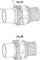
FIGS. 4A and 4B are perspective views of the connector ofFIGS. 2 and 3 in an unassembled state (FIG. 4A ) and an assembled state (FIG. 4B ); -
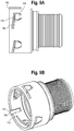
FIGS. 5A and 5B are perspective views of the female housing and slide ring of the connector ofFIG. 2 ; -
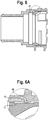
FIG. 6 is a sectional illustration of the female housing showing a retaining nub; -
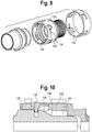
FIG. 7 is a perspective view of another embodiment of the quick connector; -
FIG. 8 is an exploded view of the connector ofFIG. 7 ; -
FIGS. 9A and 9B are side and perspective views of the female housing of the connector ofFIGS. 7 and8 ; -
FIG. 10 is a partial sectional view showing a female housing catch element engaging a groove in the male adapter; -
FIG. 11 is a perspective illustration of the female housing of still another embodiment of the quick connector; -
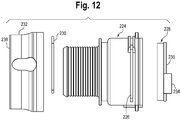
FIG. 12 is an exploded view of the housing ofFIG. 11 ; -
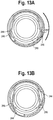
FIGS. 13A and12B illustrate the spring clip of the housing ofFIG. 11 in the unlocked state (13A) and the locked state (13B); -
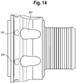
FIG. 14 is an illustration of the female housing ofFIG. 11 having a visual state indicator; -
FIG. 15 is a perspective view of still another embodiment of the quick connector with the male adapter shown shadowed; -
FIG. 16 is a sectional view of the quick connector ofFIG. 15 , shown with the male adapter being inserted into the female housing; -
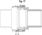
FIG. 17 is a view similar toFIG. 16 showing the male adapter further inserted into the female housing, with the male adapter in position to urging the locking finger into the free position; -
FIG. 18A and 18B are perspective views of the female housing ofFIGS. 15-17 ,FIGS. 18A and 18B being rotated about 180 degrees relative to one another; -
FIG. 19 is a perspective view of the outer ring of the housing ofFIG. 15 ; -
FIGS. 20A and 20B are perspective views of the connector shown in the unassembled (FIG. 20A ) and assembled (FIG. 20B ) states; -
FIG. 21 is a perspective illustration of yet another embodiment of the quick connector with the male adapter shown shadowed; -
FIG. 22 is an exploded view of the connector ofFIG. 21 ; -
FIGS. 23A and 23B are perspective views of the connector shown in the unassembled (FIG. 23A ) and assembled (FIG. 23B ) states; -
FIG. 24 is an exploded view of still another embodiment of the quick connector; -
FIGS. 25A-25B are perspective views of the connector shown in the unassembled (FIG. 25A ) and assembled (FIG. 25B ) states; -
FIGS. 26A and26B are exploded and perspective views of the female housing still another embodiment of the quick connector; and -
FIGS. 27A and27B are exploded and perspective views of the female housing of yet another embodiment of the quick connector. - While the present device is susceptible of embodiment in various forms, there is shown in the drawings and will hereinafter be described presently preferred embodiments with the understanding that the present disclosure is to be considered an exemplification of the device and is not intended to be limited to the specific embodiments illustrated.
-
FIG. 1 illustrates an example of a known quick connector coupling 1. The coupling 1 includes, generally, amale adapter 2, afemale housing 3, an O-ring 4, a sealingring 5 and a spring clip or clamp 6. The O-ring is fitted into an O-ring groove 7 in thefemale housing 3. The sealingring 5 is positioned in thefemale housing 3, abutting the O-ring 4. Thehousing 3 includes a pair of opposing elongatedcircumferential openings 8 between anopen end 9 of thehousing 3 and thesealing ring 5. The spring clip 6 is positioned on thehousing 3 such thatlegs 10 of the clip 6 are positioned in thecircumferential openings 8 and extend into an interior 11 of thehousing 3. - The
male adapter 2 includes a first orouter end 12 and a second or inner end 13 (inner referring to that end that inserts into the female housing 3). A slopedcollar 14 and astop wall 15 are positioned intermediate the outer and inner ends 12, 13 and define agroove 16 therebetween. The slopedcollar 14 is positioned between thestop wall 15 and theinner end 13. When theadapter 2 is inserted intohousing 3, theclip legs 10 ride up on the slopedcollar 14 and fall or lock into thegroove 16 in theadapter 2 to secure theadapter 2 andhousing 3 to one another. Themale adapter 2 can also include an aligningprojection 17. When secured to one another, the madeadapter 2 passes though the sealingring 5 and O-ring 4 and forms a seal between theadapter 2, the O-ring 4 and thehousing 3. - Referring now to
FIGS. 2-6 , there is shown an embodiment of a quick connector withpositive locking indication 20. Theconnector 20 includes generally, afemale housing 22 assembly that cooperates with, e.g., receives amale adapter 24. Thefemale housing assembly 22 includes anextended sealing ring 26, aseal 28 and aspring clip 30. In an embodiment theseal 28 can be a V-seal, such as that illustrated inFIG. 3 . Other types and configurations of seals can be used, such as O-ring seals and will be recognized by those skilled in the art. Thespring clip 30 is of a known type in which thelegs 32 are biased inwardly; that is thelegs 32 are biased toward one another. - The
housing 22 includes aninlet end 34 having a series ofpockets 36 formed therein. A ring groove 38 (V-ring or O-ring groove as the case may be) is present in thebody 40 of thehousing 22, spaced from theinlet 34. It will be appreciated that other types and profiles of seals and cooperating ring grooves can be used and are within the scope and spirit of the present disclosure. A pair of opposing elongatedcircumferential openings 42 are formed in thebody 40, between theinlet end 34 and thering groove 38. Thebody 40 can include aguide 44, such as the upstanding guide walls to maintain thespring clip 30 positioned on thebody 40, clip end rests 46, finger recesses 48 to assist a user in grasping and manipulating thehousing 22 and a connectingend 50, to which a hose or component is connected to thehousing 22. - Referring again to the
pockets 36, in an embodiment, thepockets 36 are elongated semi-circular shaped niches formed in theinlet end 34 of thebody 40. Thepockets 36 can be irregularly circumferentially spaced from one another. Thepockets 36 can be the same size and shape or can have different sizes and shapes from one another. - The
extended sealing ring 26 is best illustrated inFIG. 3 . Thering 26 includes aring abutment portion 52 that abuts the seal 28 (V-ring or O-ring seal), abody portion 54 and anend portion 56. Theend portion 56 includes a series of projections orlips 58 that cooperate with thepockets 36 in thehousing body 40. In this manner, when the sealingring 26 is properly seated in thehousing 22, thering 36 abuts theseal 28 and thering projections 58 are positioned in thehousing pockets 26 to provide visual indication that the 26 ring is properly positioned in thehousing 22 and that themale adapter 24 is properly seated in thehousing 22. - The sealing
ring 26 can also include a pair of opposing elongatedcircumferential openings 60 formed in thebody 40 so that when the sealingring 26 is fully positioned in thehousing 22, theopenings 60 are aligned with the opposing elongatedcircumferential openings 42 formed in thehousing body 40. In addition, when the sealingring 26 is fully seated within thehousing 22, thehousing openings 42 and thering openings 60 are aligned with one another which permits thespring clip legs 32 to open within theopenings adapter 24 to thehousing 22. - In an embodiment, the sealing
ring 26 includes one or more longitudinal aligningchannels 64 to accommodate one or more cooperating aligningprojections 66 on themale adapter 24. Mating the maleadapter aligning projections 66 with the aligningchannels 64 facilitates properly circumferentially aligning themale adapter 24 with the female housing 22 (to properly align the components/conduits that are being connected by the quick connect coupling 20). - The
housing 22 can also include aring retaining element 68 to maintain thering 26 mounted to thehousing 22, even with themale adapter 24 removed (in an unassembled state). As seen inFIG. 6 , thehousing 22 includes one ormore detents 70 formed extending inwardly of thehousing body 40, between theinlet 34 and thering groove 38. Thedetents 70 cooperate with acircumferential channel 72 in thering 26 and interfere with removal of thering 26 from thehousing 22. Thechannel 72 is sufficiently wide so that thering 26 can move longitudinally, between the unassembled and assembled states. - Referring to
FIGS. 4A and 4B , theconnector 20 is shown in an unassembled or unlocked state and a locked state, respectively. InFIG. 4A , themale adapter 24 is being inserted into thehousing 22, but is not yet fully inserted into thehousing 22 and thering 26 is not seated in thehousing 22. This is shown by the non-alignment of thering projections 58 and housing pockets 36. - With the
male adapter 24 properly aligned with the housing 22 (theadapter projection 66 is aligned with the aligning channel 64), themale adapter 24 is urged into the sealingring 26 and theadapter 24 and sealingring 26 are urged into thehousing 22. With theprojections 58 andpockets 36 properly aligned, the elongatedcircumferential openings housing body 40 and sealingring 26 are also aligned, and theclip legs 32 fall into place in the openings and in theadapter groove 62, as theadapter 24 is urged forward into thehousing 22. Alignment of thering projections 58 in thepockets 36 provides positive, visual indication that themale adapter 24 is fully seated in thehousing 22 and locked in place. The alignment of thering projections 58 in thepockets 36 also provides tactile indication in that a user can feel whether theprojections 58 are aligned in thepockets 36 in that there will be a smooth transition between theprojections 58 and thepockets 36. As noted above, when themale adapter 24 is fully seated in thefemale housing 22 and sealingring 26, the housing andring openings spring clip legs 32 lock into themale adapter groove 62. - To remove the
male adapter 24 from thehousing 22, theclip 30 is pulled to an unseated state (pulled up) so that the ends of theclip legs 32 rest in the clip end rests 46 and themale adapter 24 is urged from thehousing 22. This also unseats the sealing ring 26 (so that theprojections 58 are unseated from the pockets 36). To reset theconnector 20, theclip 30 is urged by downward onto thehousing 22 so that theclip legs 32 are once again in the elongatedcircumferential openings 42 in thehousing 22. - An embodiment of the quick connector with
positive locking indication 120 is illustrated inFIGS. 7-10 . In this embodiment, thehousing 122 includes one or more inwardly orientedflexible catch elements 124 that cooperate with thecircumferential groove 62 in themale adapter 24. As with the prior embodiment thehousing 122 includes aring groove 126 internally to accommodate a seal such as a V-ring or O-ring seal (not shown) and theconnector 120 includes asealing ring 128. - The
catch elements 124 are formed (for example, when molded) so that in a resting or unassembled state anoutside surface 130 of theelements 124 is flush with anoutside surface 132 of thehousing 122. A shortcircumferential channel 134 is formed in thehousing 122 along an end of thecatch elements 124 and is contiguous with ashort leg 136 of thechannel 134 that extends a distance beyond and adjacent to an end of theelements 124. Thehousing 122 can include one or more longitudinal aligningchannels 138 to accommodate one or more cooperating aligningprojections 66 on themale adapter 24. The aligningchannels 138 can be formed by outwardly projectingwalls 140 having aninner channel 142 to accommodate the aligningprojections 66. - An
outer twist ring 144 is positioned on thehousing 122 overlying thecatch elements 124. Thetwist ring 144 includes one ormore windows 146, each configured to cooperate with one of thecatch elements 124. In an unlocked state, thewindows 146 overlie acatch element 124. An outwardly projectingslide wall 148 is positioned over the outwardly projectingwall 140 that defines the aligningchannel 138. Theslide wall 148 is wider than the aligningchannel wall 140 to permit thetwist ring 144 to move (to be rotated) so that thewindows 146 overlie thecatch elements 124 and block thecatch elements 124 to prevent theelements 124 from flexing outwardly. - In use the
twist ring 144 is rotated to the unlocked state, in which thewindows 146 overlie thecatch elements 124. Themale adapter 24 is aligned with thehousing 122 so that the aligningchannels 138 andadapter projections 66 are aligned with one another. As theadapter 24 is urged into thehousing 122, the sloped collar 61 engages thecatch elements 124 and thecatch elements 124 ride up along the collar 61. When theadapter 24 is fully engaged with thehousing 122, thecatch elements 124 will engage or seat in theadapter groove 62. Once thecatch elements 124 are fully seated in thegroove 62, thetwist ring 144 can be rotated so that the solid wall portion of thering 144 overlies thecatch elements 124 and prevents thecatch elements 124 from flexing outward and disengaging from theadapter groove 62. To maintain thering 144 on thehousing 124, thering 144 can include a series oftongues 150 that extend inwardly of thering 144, adjacent to thewindows 146. Thetongues 150 traverse through and along thecircumferential channel 134 along the end of and adjacent thecatch elements 124. This provides a guide along which thering 144 is captured, but can rotate, back and forth, to expose and cover thewindows 146, while ensuring that thering 144 remains on thehousing 122. - Because the
catch elements 124 must fully engage theadapter groove 62 to allow thering 144 to rotate, theconnector 120 provides positive indication that themale adapter 24 is fully engaged with and seated in thehousing 122 when thering 146 is rotated to the locked position. If theadapter 24 is not fully seated in thehousing 122, thering 144 cannot rotate as thecatch elements 124 will extend above thehousing surface 132 and into thering windows 146. - Still another embodiment of the quick connector with
positive locking indication 220 is illustrated inFIGS. 11-14 . Thefemale housing 222 includes abody 224 having elongatedcircumferential openings 226, a slidingring 228 positioned in thebody 224, aspring clip 230 that is biased outwardly, and atwist ring 232. The slidingring 228 has atab 234 extending forwardly from afront edge 236 thereof, toward an open end of thehousing 222. Theoutside surface 238 of thetwist ring 232 can havefinger recesses 240 to assist a user in grasping and manipulating thetwist ring 232. Visual indicators, such asarrows 242, or other markers can be present on thetwist ring 232 and on thehousing body 224. Tactile indication may also be provided if themarkers 242 are raised from the surfaces of thetwist ring 232 andhousing body 224 and allow the user to feel whether they are aligned with one another. - The
twist ring 232 has a series ofinternal pockets 244 in which thespring clip legs 246 reside when thefemale housing 222 is in an unlocked state. Thepockets 244 allow thelegs 246 to expand outwardly. Rotating thetwist ring 232 moves theclip legs 246 out of thepockets 244 and compresses thelegs 246 inwardly. Referring toFIGS. 12 and13A , without themale adapter 24 seated in thehousing 222, thefront edge 236 of the slidingring 228, which is in a forward position (toward the open end of the housing) and thetab 234 interfere with and prevent thelegs 246 from compressing, which in turn prevents thetwist ring 232 from rotating. When themale adapter 24 is inserted into thehousing 222, theadapter 24 contacts thetab 234 and the slidingring 228 which urges the slidingring 228 into thehousing 222, which moves the slidingring 228 out of interference with theclip legs 246. Thetwist ring 232 can then be rotated which in turn moves theclip legs 246 out of thepockets 244 and compresses thelegs 246 which lock into themale adapter groove 62. Themarkers 242 on thetwist ring 232 andhousing body 224 can be positioned so that themarkers 242 align when thetwist ring 232 is in the locked state. Thequick connector 220 thus provides positive visual indication of the state of theconnector 220 by visually inspecting alignment of themarkers 242 on thetwist ring 232 andhousing body 224. If thealignment markers 242 are raised on or recessed in thetwist ring 232 andhousing body 224, tactile indication can also be provided. - Yet another embodiment of the quick connector with
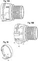
positive locking indication 320 is illustrated inFIGS.15-20B . Thefemale housing 322 includes ahousing body 324 and an external slidingindicator ring 326 to provide positive indication of locking of themale adapter 24 andfemale housing 320. The longitudinal location of the slidingindicator ring 326 on thehousing 322 indicates the state of theconnector 320. - In this embodiment the
housing 322 is formed having elongatedcircumferential openings 328 to accommodate a spring clip (not shown) and one or more longitudinal aligningchannels 330 to accommodate one or more cooperating aligningprojections 66 on themale adapter 24. - Referring to
FIG. 16 , in an embodiment, the slidingindicator ring 326 includes a pair of circumferentially opposing inwardly orientedflexible tabs 332 that engage achannel 334 in thehousing body 324. Thetabs 332 engage thechannel 334 as the slidingindicator ring 326 slides between a first or forward position (FIG. 16 ) in which thering 326 indicates that themale adapter 24 is not fully engaged with thehousing 322 and a second rearward position (FIG. 17 ) in which thering 326 indicates that themale adapter 24 is fully engaged with thehousing 322. Thetabs 332 are biased outwardly to maintain positive engagement with thehousing 322 and are prevented from passing beyond the fully engaged position bystop walls 336 in thechannel 334. - As illustrated in
FIGS. 16 and19 , the slidingindicator ring 326 includes an additional tab, arelease tab 338, that is forward of the pair oftabs 332. Therelease tab 338 moves within arelease tab channel 340 that is formed in one of thefirst tab channels 334 and is further open to one of the longitudinal aligningchannels 330 in thehousing body 324. Therelease tab 338 locks and releases the slidingindicator ring 326 to prevent or allow movement of thering 326 between the forward and rearward positions. Therelease 338 tab is biased outwardly and engages astop wall 342 in therelease tab channel 340 to prevent movement of the sliding indicator ring 326 (seeFIG. 16 ). - Referring to
FIG. 17 , therelease tab 338 is configured to cooperate with one of the maleadapter aligning projections 66. As themale adapter 24 is inserted into thehousing 322, the aligningprojection 66 contacts therelease tab 338 and urges therelease tab 338 outwardly, which disengages therelease tab 338 from the releaser tabchannel stop wall 342. This allows the slidingindicator ring 326 to slide rearwardly, to indicate that themale adapter 24 is fully seated in thehousing 322 and is locked in place. - Still another embodiment of the quick connector with
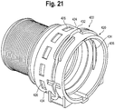
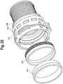
positive locking indication 420 is illustrated inFIGS. 21-23B . In this embodiment, thefemale housing 422 includes abody 424 having a plurality of circumferentially extendingwindows 426, anindicator ring 428 , a slidingring 430 and aspring clip 432. Theindicator ring 428 can be formed, for example, having two colors, for example, a red portion and a black portion, each extending along a longitudinal portion of theindicator ring 428. Theindicator ring 428 is engaged by the slidingring 430 and is moved longitudinally through thehousing body 424 by the slidingring 430. - Referring to
FIGS. 23A and B , in the unassembled state (FIG. 23A ), themale adapter 24 is not yet fully engaged with thehousing 422 and the sliding and indicator rings 430, 428, and a forward portion or color (for example, the black portion) of theindicator ring 428 visible in thewindows 426. As themale adapter 24 is fully engaged with thehousing 422, the slidingring 430 urges theindicator ring 428 rearward so that the second portion or color (for example, the red portion) of theindicator ring 428 is visible in thewindows 426. In this position, theindicator ring 428 is beyond the housinglongitudinal openings 434 and theclip legs 436 have passed over the sloped collar 61 and locked into thegroove 62 in theadapter 24 to secure theadapter 24 andhousing 422 to one another. - Yet another embodiment of the quick connector with
positive locking indication 520 is illustrated inFIGS. 24-25B . In this embodiment, anend 522 of the slidingring 524 is an external indicator to indicate the state of theconnector 520. The slidingring 524 has a pair of circumferentially opposedopenings 526 that cooperate with the spring clip legs 528. When in the unassembled state (FIG. 25A ), theend 522 of thering 524 is exposed indicating that themale adapter 24 is not engaged with thefemale housing 530, and the wall of the slidingring 524 adjacent to theopenings 526 interferes with the spring clip legs 528 closing. With themale adapter 24 fully seated in thehousing 530 it urges the slidingring 524 rearward, into the housing 530 (to hide theend 522 of the sliding ring 524 - the indicating portion) and theopposed openings 526 in the slidingring 524 align with thehousing openings 532 and clip legs 528 to allow the clip legs 528 to close into themale adapter groove 62. - Still another embodiment of the quick connector with
positive lock indication 620, is shown inFIGS. 26A and26B . In this embodiment, thefemale housing 622 includes a series ofpockets 636 and thesealing ring 626 includes a series ofprojections 658, similar to the prior embodiments. Thering 626 can include an aligning projection (not shown) that cooperates with the femalehousing aligning channel 664 to ensure that thering 626 andfemale housing 622 are properly aligned. The other features, such as those to support and retain thespring clip 630 on thefemale housing 622 and between and when thering 626 is properly seated in thefemale housing 622 are also present in this embodiment. - A
seal 628 is positioned in thefemale housing 622 and sits between aseal abutment 668 thefemale housing 622 and thesealing ring 626 when the sealingring 626 is in place in thehousing 622. - As best seen in
FIG. 26A , anend 676 of the sealingring 626 includes a series of helical or spiral formedlegs 678 that define a circumferential radius about equal to the circumference of the sealingring end 676. That is, thelegs 678 are axially aligned with the sealingring end 676. Thelegs 678 are formed so as to flex toward and away from the sealingring end 676, and to bias thesealing ring 626 away from thefemale housing 622, to unseat thesealing ring 626 and as such, to unseat the sealingring projections 658 from the female housing pockets 636. - In an embodiment, the
legs 678 contact or cooperate with anabutment 668 in thehousing 622. That is, thelegs 678 compress against the abutment portion 688 as the sealingring 626 properly seats in thehousing 622. This arrangement provides, as in the prior embodiments, both visual and tactile indication of whether the sealingring 626 is properly seated in thefemale housing 622 in that theprojections 658 are seated in and flush with thepockets 636 when the sealingring 626 is properly seated in thehousing 622. - The
legs 678 can be formed through wall, that is formed from the entirety of the thickness of the wall at the sealingring end 676, or it they can be formed from a portion of the wall, that is less than the entire thickness of theend 676 wall. When formed as a portion of the thickness of theend 676 wall, thelegs 678, when flexed rearward, can seat inrecesses 680 in the wall. Such a configuration facilitates protecting thelegs 678. Moreover, in this configuration, the circumferential arrangement of thelegs 678 is such that they do not occupy the area in which thesealing ring 626 acts to retain theseal 628 in place in thehousing 622. The housing can be formed with slots or cut-outs 682 in the sidewall to accommodate thelegs 678 and to prevent rotation of the sealingring 626 relative to thehousing 622. - Yet another embodiment of the quick connector with
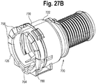
positive lock indication 720, is shown inFIGS. 27A and27B . In this embodiment, thefemale housing 722 includes a series ofpockets 736 and thesealing ring 726 includes a series ofprojections 758, similar to the prior embodiments. Thering 726 can include an aligning projection (not shown) that cooperates with the femalehousing aligning channel 764 to ensure that thering 726 andfemale housing 722 are properly aligned. The other features, such as those to support and retain thespring clip 730 on thefemale housing 722 and between and when thering 726 is properly seated in thehousing 722 are also present in this embodiment. - A
seal 728 is positioned in thefemale housing 722 and sits between anabutment 768 in thefemale housing 722 and thesealing ring 726 when thering 726 is in place in thehousing 722. - As best seen in
FIG. 27A an end 775 of thering 726 includes a circumferential abutment portion 752. In an embodiment, anintermediate portion 769 of the sealingring 726 includes a partiallyopen region 770 having a pair of linear or generally longitudinally extendingflexible legs 772 that depend from anend 756 proximal theprojections 758. Thelegs 772 are formed radially outwardly of the abutment portion 752. Thelegs 772 are configured to flex outwardly, circumferentially from each other and serve as a spring, as is detailed below. In an embodiment, two pairs oflegs 772 are formed, each on circumferentially opposing sides of thering 726. - The
female housing 722 includes a receivingregion 774 to receive thering legs 772. In an embodiment, the receivingregion 774 includes a longitudinally extending wedge-shaped projection orwall 776 on an inner surface 778 thereof. Thewedge wall 776 is configured to cooperate with thelegs 772 to bias thesealing ring 726 outwardly, away from thehousing 722 until it is full seated in thehousing 722. In an embodiment, thewedge wall 776 has a pair of mirror-image wedges 780 that cooperate with the pair oflegs 772. In an embodiment, thefemale housing 722 has receivingregions 774 formed on circumferentially opposing sides of thehousing 722 to accommodate asealing ring 726 configuration having a two pairs oflegs 772. In some embodiments, the sealingring 726 includes an aligning projection (not shown) that cooperates with the housing aligning channel 764 (and as illustrated in the prior embodiments) to assure that the sealingring 726 andfemale housing 722 are properly aligned with one another. The aligning projection can be positioned between thelegs 772 of one of the pair of legs and the aligningchannel 764 can, likewise, be positioned between thewedges 780 of one of the receivingregions 774. This arrangement provides, as in the prior embodiments, both visual and tactile indication of whether the sealingring 726 is properly seated in thefemale housing 722 in that theprojections 758 are seated in and flush with thepockets 736 when the sealingring 726 is properly seated in thehousing 722. - In addition to the biasing function provided by the
legs 772 acting against or cooperating with thewedges 780, the interaction of thelegs 772 in the receivingregions 774 serves to prevent rotation of the sealingring 726 relative to thehousing 722. - It will be appreciated that in the
embodiments FIGS. 26A ,B and27A ,B , the sealing ring is translated between the seated and unseated positions by a component other than the seal, by an axial force applied to the sealing ring. In the embodiment ofFIGS. 26A ,B the force is provided by a sealing ring having spiral orhelical legs 678 that cooperate with theabutment wall 668 to unseat the sealing ring from thehousing 622 and in the embodiment ofFIGS. 27A ,B , the force is provided bylinear legs 772 that cooperate with thewedges 780. It will, however, be appreciated that the bias function can be provided using other spring configurations. - In addition, the under-surfaces of the
projections rings respective housings - It will be appreciated by those skilled in the art that the seal (such as that shown in
FIG. 3 ), for example, the V-seal, is required in each of the disclosed embodiments, whether shown or described. It will, however, be appreciated that other types and profiles of seals and cooperating ring grooves can be used and are within the scope and spirit of the present disclosure. - It will also be appreciated from the above disclosure and the accompanying figures that the present quick connector with positive lock indication provides numerous advantages over known quick connect couplings. Whereas known coupling function well to secure the male adapter to the female housing they lack the visual or tactile indication of secure connection or coupling of the male adapter and female housing provided by the present connector.
- It will also be appreciated by those skilled in the art that the relative directional terms such as upper, lower, rearward, forward and the like are for explanatory purposes only and are not intended to limit the scope of the disclosure.
- All patents referred to herein, are incorporated herein by reference, whether or not specifically done so within the text of this disclosure.
- In the present disclosure, the words "a" or "an" are to be taken to include both the singular and the plural. Conversely, any reference to plural items shall, where appropriate, include the singular.
- From the foregoing it will be observed that numerous modifications and variations can be effectuated without departing from the true spirit and scope of the novel concepts of the present disclosure. It is to be understood that no limitation with respect to the specific embodiments illustrated is intended or should be inferred. The disclosure is intended to cover all such modifications as fall within its scope.
- Certain implementations are described in the following numbered clauses:
- 1. A quick connector assembly comprising:
- a male adapter portion having an end and a groove formed therein spaced from the end, the male adapter portion having a through bore;
- a female housing portion having a body, the body having a through bore generally concentrically aligned with the male adapter portion through bore;
- a ring cooperating with the female housing portion and the male adapter portion, wherein the ring is in a first position when the male adapter is engaged with the female housing and wherein the ring is in a second position, different from the first position, when the male adapter is other than engaged with the female housing.
- 2. The connector assembly of clause 1 wherein the first and second positions are visually different from one another.
- 3. The connector assembly of clause 1 including tactile indication that the male adapter is engaged with the female housing and that the male adapter is not engaged with the female housing.
- 4. The connector assembly of clause 1 wherein an end of the housing includes one or more pockets formed therein and wherein the ring includes one or more projections configured to cooperate with the one or more pockets to provide visual and tactile indication that the male adapter is engaged with the female housing.
- 5. The connector assembly of
clause 4 wherein the housing includes a series of pockets and the ring includes a series of projections. - 6. The connector assembly of
clause 5 wherein the series of pockets and the series of projections are circumferentially arranged around the female housing and ring, respectively, such that the ring will engage the female housing only in a single circumferential orientation. - 7. The connector assembly of clause 1 wherein the female housing includes a pair of opposing elongated circumferential openings, and wherein the connector assembly includes a spring clip having legs disposed in the opposing elongated circumferential openings, the spring clip legs configured to cooperate with and engage a groove in the male adapter to secure the male adapter in the female housing.
- 8. The connector assembly of clause 1 wherein the ring is a rotating twist ring and includes a window therein, wherein the female housing includes an inwardly oriented flexible catch element that, in a resting state, is flush with an outside surface of the female housing, and wherein less than full insertion of the male adapter into the housing moves the catch element from the resting state into the window and interferes with rotation of the twist ring and full insertion of the male adapter into female housing allows the catch element to return to the resting state and out of the window, and does not interfere with rotation of the twist ring.
- 9. The connector assembly of
clause 8 wherein the when the male adapter is fully engaged with the female housing, the twist ring is rotated so that the windows are out of alignment with the catch elements, the catch elements are prevented from moving outwardly and the male adapter is secured in the female housing. - 10. The connector assembly of
clause 8 including a plurality of flexible catch elements formed on the housing and wherein the twist ring includes respective cooperating windows for each of the plurality of flexible catch elements. - 11. The connector assembly of
clause 8 including a circumferential channel formed along an end of and adjacent the catch element, and wherein the ring includes an inwardly projecting tongue adjacent to the window the tongue traversing through the channel as the ring is rotated to align the window with the catch element. - 12. The connector assembly of
clause 11 including a plurality of catch elements and respective cooperating windows. - 13. The connector assembly of clause 1, wherein the female housing includes a radial shoulder at an interior portion thereon, wherein the connector assembly includes a seal positioned in the female housing abutting the radial shoulder, and wherein when the male adapter is engaged with the female housing the seal is urged against the radial shoulder.
- 14. The connector assembly of
clause 13 including a sliding ring outboard of the seal, wherein the male adapter engages the sliding ring to urge the seal against the radial shoulder. - 15. The connector assembly of
clause 13 wherein the seal is a V-seal. - 16. The connector assembly of clause 7 wherein the female housing includes a radial shoulder at an interior portion thereon, and wherein the connector assembly includes a seal positioned in the female housing abutting the radial shoulder and a sliding ring outboard of the seal, the ring being a rotating twist ring having pockets for receiving the spring clip legs when the female housing is in an unlocked state.
- 17. The connector assembly of
clause 16 wherein the sliding ring includes an edge to interfere with rotating the twist ring when the male adapter is disengaged from the female housing and wherein when the male adapter is engaged with the female housing the sliding ring is urged inwardly of the female housing moving the edge out of interfering with movement of the twist ring and the spring clip legs are urged inwardly to engage the groove in the male adapter to secure the male adapter in the female housing. - 18. The connector assembly of
clause 17 wherein the twist ring and the female housing include visual indicia to indicate when the twist ring is in a locked position and an unlocked position. - 19. The connector assembly of clause 7 wherein the connector assembly includes an external sliding indicator ring positioned on the housing, the external sliding indicator including a pair of circumferentially spaced inwardly oriented flexible first tabs that engage a pair of channels in the housing body, the first tabs engaging the channels as the sliding indicator ring slides between a first position in which the ring indicates that the male adapter is not fully engaged with the housing and second position in which the ring indicates that the male adapter is fully engaged with the housing, the sliding indicator ring including a release tab movable within a release tab channel formed in one of the first tab channels, the release tab flexing between a locked position and a release position to lock and allow movement, respectively, of the sliding indictor ring between the first and second positions.
- 20. The connector assembly of clause 7 wherein the housing includes a plurality of circumferentially disposed windows therein, and wherein the connector assembly includes a ring positioned internally of the female housing, the ring having first and second colors thereon along longitudinally disposed sections of the ring, wherein when the first color is visible in the windows the ring indicates that the male adapter is not fully engaged with the housing and when the second color is visible in the windows the ring indicates that the male adapter is fully engaged with the housing.
- 21. The connector assembly of clause 7 including an internal sliding indicator ring positioned in the female housing, the internal sliding indicator ring having a portion that is visible between the female housing and the male adapter when the male adapter is not fully engaged with the housing and is not visible when the male adapter is fully engaged with the housing.
- 22. The connector assembly of clause 1 wherein the ring includes at least one biasing element and wherein the female housing portion body includes an abutment portion, the at least one biasing element cooperating with the abutment portion to bias the ring to the second position.
- 23. The connector assembly of
clause 22 wherein the biasing element is a helical formed leg extending from about an end of the ring. - 24. The connector assembly of clause 23 including a plurality of helical formed legs.
- 25. The connector assembly of
clause 24 including pockets formed in the ring that cooperate and receive with the legs when the male adapter is fully engaged with the female housing. - 26. The connector assembly of
clause 22 wherein the ring includes a pair of longitudinally extending flexible legs depending from about an end of the ring, and wherein the female housing incudes a receiving region on an inner surface thereof for receiving the legs. - 27. The connector assembly of
clause 26, wherein the receiving region includes a wedge-shaped projection cooperating with the longitudinally extending flexible legs to bias the ring to the second position. - 28. The connector assembly of clause 27 including a pair of longitudinally extending flexible legs in opposing relation to one another and a pair of wedge-shaped projection in opposing relation to one another.
- 29. The connector assembly of
clause 28 including two pairs of longitudinally extending flexible legs in each pair in opposing relation to each other and two pairs of wedge-shaped projection each pair in opposing relation to each another.
Claims (11)
- A quick connector assembly comprising:a male adapter portion having an end and a groove formed therein spaced from the end, the male adapter portion having a through bore;a female housing portion having a body, the body having a through bore generally concentrically aligned with the male adapter portion through bore;a ring cooperating with the female housing portion and the male adapter portion, wherein the ring is in a first position when the male adapter is engaged with the female housing and wherein the ring is in a second position, different from the first position, when the male adapter is other than engaged with the female housing,wherein an end of the housing includes one or more pockets formed therein andwherein the ring includes one or more projections configured to cooperate with the one or more pockets to provide visual and tactile indication that the male adapter is engaged with the female housing.
- The connector assembly of claim 1, wherein the housing includes a series of pockets and the ring includes a series of projections.
- The connector assembly of claim 2, wherein the series of pockets and the series of projections are circumferentially arranged around the female housing and ring, respectively, such that the ring will engage the female housing only in a single circumferential orientation.
- The connector assembly of any preceding claim, wherein the one or more pockets are elongated semi-circular shaped notches formed in an inlet end of the body of the female housing portion.
- The connector assembly of any preceding claim, wherein the female housing includes a pair of opposing elongated circumferential openings, and wherein the connector assembly includes a spring clip having legs disposed in the opposing elongated circumferential openings, the spring clip legs configured to cooperate with and engage a groove in the male adapter to secure the male adapter in the female housing.
- The connector assembly of any preceding claim, wherein the female housing portion includes a ring retaining element.
- The connector assembly of claim 6, wherein the ring retaining element comprises one or more detents formed extending inwardly of the body of the female housing portion, between an inlet and a ring groove.
- The connector assembly of claim 7, wherein the one or more detents are configured to cooperate with a circumferential channel in the ring.
- A quick connector assembly comprising:a male adapter portion having an end and a groove formed therein spaced from the end, the male adapter portion having a through bore;a female housing portion having a body, the body having a through bore generally concentrically aligned with the male adapter portion through bore, and a pair of opposing elongated circumferential openings; anda ring cooperating with the female housing portion and the male adapter portion,wherein the ring is in a first position when the male adapter is engaged with the female housing and wherein the ring is in a second position, different from the first position, when the male adapter is other than engaged with the female housing,wherein the connector assembly further comprises a spring clip having legs disposed in the opposing elongated circumferential openings, the spring clip legs configured to cooperate with and engage a groove in the male adapter to secure the male adapter in the female housing; andwherein the ring is an internal sliding indicator ring positioned in the female housing portion, the internal sliding indicator ring having a portion that is visible between the female housing and the male adapter when the male adapter is not fully engaged with the housing and is not visible when the male adapter is fully engaged with the housing.
- The connector assembly of claim 9, wherein an end of the internal sliding ring is visible between the female housing and the male adaptor when the male adaptor is not fully engaged with the housing, and wherein the end of the internal sliding ring is not visible between the female housing and the male adaptor when the male adaptor is fully engaged with the housing.
- The connector assembly of claim 9 or claim 10, wherein the internal sliding ring includes a pair of circumferentially opposed opening that cooperate with the spring clip legs.
Applications Claiming Priority (3)
| Application Number | Priority Date | Filing Date | Title |
|---|---|---|---|
| US201662428815P | 2016-12-01 | 2016-12-01 | |
| EP17817445.4A EP3548785B1 (en) | 2016-12-01 | 2017-11-22 | Quick connector with locking ring |
| PCT/US2017/062985 WO2018102213A1 (en) | 2016-12-01 | 2017-11-22 | Quick connector with positive lock indication |
Related Parent Applications (2)
| Application Number | Title | Priority Date | Filing Date |
|---|---|---|---|
| EP17817445.4A Division EP3548785B1 (en) | 2016-12-01 | 2017-11-22 | Quick connector with locking ring |
| EP17817445.4A Division-Into EP3548785B1 (en) | 2016-12-01 | 2017-11-22 | Quick connector with locking ring |
Publications (2)
| Publication Number | Publication Date |
|---|---|
| EP3715691A2 true EP3715691A2 (en) | 2020-09-30 |
| EP3715691A3 EP3715691A3 (en) | 2020-10-28 |
Family
ID=60703071
Family Applications (2)
| Application Number | Title | Priority Date | Filing Date |
|---|---|---|---|
| EP20174975.1A Withdrawn EP3715691A3 (en) | 2016-12-01 | 2017-11-22 | Quick connector with positive lock indication |
| EP17817445.4A Active EP3548785B1 (en) | 2016-12-01 | 2017-11-22 | Quick connector with locking ring |
Family Applications After (1)
| Application Number | Title | Priority Date | Filing Date |
|---|---|---|---|
| EP17817445.4A Active EP3548785B1 (en) | 2016-12-01 | 2017-11-22 | Quick connector with locking ring |
Country Status (3)
| Country | Link |
|---|---|
| US (1) | US11480277B2 (en) |
| EP (2) | EP3715691A3 (en) |
| WO (1) | WO2018102213A1 (en) |
Families Citing this family (29)
| Publication number | Priority date | Publication date | Assignee | Title |
|---|---|---|---|---|
| DE102018219440A1 (en) | 2018-11-14 | 2020-05-14 | Fränkische Industrial Pipes GmbH & Co. KG | Connecting unit |
| CN110043731B (en) * | 2019-04-12 | 2020-11-10 | A.雷蒙德公司 | Quick connector |
| EP3736481B1 (en) * | 2019-05-07 | 2022-01-19 | A. Raymond et Cie | Quick connector assembly with verification tab |
| US11796099B2 (en) | 2019-08-22 | 2023-10-24 | Cooper-Standard Automotive Inc. | Connector having a pilot with an indicator |
| AT522804B1 (en) | 2019-09-03 | 2021-02-15 | Henn Gmbh & Co Kg | Connectors for connecting lines for liquid or gaseous media |
| ES2823374B2 (en) * | 2019-11-05 | 2022-05-06 | Cikautxo S Coop | Connector assembly with assembly detection and simultaneous code visualization |
| DE102020108073A1 (en) * | 2020-03-24 | 2021-09-30 | Voss Automotive Gmbh | Connector with pre-assembly lock |
| EP3904747B1 (en) * | 2020-04-27 | 2024-02-14 | Illinois Tool Works Inc. | Female connector and connector assembly |
| CN113639120B (en) * | 2020-04-27 | 2025-12-02 | 伊利诺斯工具制品有限公司 | Female connector and connector assembly |
| AT523066B1 (en) | 2020-05-27 | 2021-05-15 | Henn Gmbh & Co Kg | Connectors for connecting lines for liquid or gaseous media |
| DE102020115021A1 (en) * | 2020-06-05 | 2021-12-09 | Norma Germany Gmbh | Device for connecting two tubular objects |
| US11698157B2 (en) | 2020-07-24 | 2023-07-11 | Cooper-Standard Automotive Inc. | Quick connector latch verification utilizing a scannable code |
| US11365840B2 (en) | 2020-11-20 | 2022-06-21 | A. Raymond Et Cie | Code verification sleeve for a quick connector |
| US11578828B2 (en) | 2020-12-03 | 2023-02-14 | Cooper-Standard Automotive, Inc. | Connector having a guided pilot |
| FR3126027B1 (en) * | 2021-08-06 | 2023-08-11 | Parker Hannifin Emea Sarl | Instant connection device |
| AT524862B1 (en) | 2021-11-09 | 2022-10-15 | Henn Gmbh & Co Kg | Connector for connecting lines for liquid or gaseous media |
| AT525044B1 (en) | 2022-01-11 | 2022-12-15 | Henn Gmbh & Co Kg | Connector assembly with a connector and a mating connector |
| WO2023133605A1 (en) | 2022-01-11 | 2023-07-20 | Henn Gmbh & Co Kg. | Plug assembly comprising a plug connector and a mating plug connector |
| AU2022202293B1 (en) * | 2022-04-06 | 2023-01-05 | Philmac Pty Ltd | A push-fit pipe fitting with a visual indicator |
| AT525974B1 (en) | 2022-09-27 | 2023-10-15 | Henn Gmbh & Co Kg | Plug connector for connecting lines for liquid or gaseous media, and a method for producing a plug connection between the plug connector and a mating plug connector |
| US20240159340A1 (en) * | 2022-11-16 | 2024-05-16 | Cooper-Standard Automotive Inc | Connector with guiding components |
| DE202023100891U1 (en) * | 2023-02-24 | 2024-02-27 | Neoperl Gmbh | Fastening device for fastening hoses to a sanitary fitting |
| AT526428B1 (en) | 2023-04-06 | 2024-03-15 | Henn Gmbh & Co Kg | Connectors |
| WO2024211950A1 (en) | 2023-04-14 | 2024-10-17 | Henn Gmbh & Co Kg. | Plug-in connector for connecting a first fluid line to a second fluid line |
| WO2024250048A1 (en) | 2023-06-05 | 2024-12-12 | Henn Gmbh & Co Kg. | Plug connector for connecting an insertion sleeve to a fluid line |
| AT526786B1 (en) | 2023-08-11 | 2024-07-15 | Henn Gmbh & Co Kg | Connector for connecting a first fluid line to a second fluid line |
| CN120312915A (en) | 2024-01-12 | 2025-07-15 | 伊利诺斯工具制品有限公司 | Female connector and connector assembly including the same |
| US12498066B1 (en) * | 2024-06-12 | 2025-12-16 | Ho Sing Enterprises Co., Ltd. | Quick connector structure of fluid shock absorber |
| US12553552B1 (en) * | 2024-08-14 | 2026-02-17 | Robert Sherwood | Conduit coupler |
Citations (2)
| Publication number | Priority date | Publication date | Assignee | Title |
|---|---|---|---|---|
| WO2013070865A2 (en) | 2011-11-10 | 2013-05-16 | Illinois Tool Works Inc. | Device for connecting two conduit sections |
| WO2016081590A1 (en) | 2014-11-20 | 2016-05-26 | Illinois Tool Works Inc. | Quick connector |
Family Cites Families (7)
| Publication number | Priority date | Publication date | Assignee | Title |
|---|---|---|---|---|
| US4948176A (en) | 1987-09-14 | 1990-08-14 | Proprietary Technology, Inc. | Swivelable quick connector assembly |
| DE102004044917A1 (en) * | 2004-09-14 | 2006-03-16 | Fte Automotive Gmbh | Detachable plug connection for pipelines or the like |
| US20060145475A1 (en) | 2004-12-30 | 2006-07-06 | Itt Manufacturing Enterprises, Inc. | Fluid quick connector with wire retainer |
| US9283344B2 (en) | 2012-01-03 | 2016-03-15 | Carefusion Corporation | Apparatus, system, and method of fluid delivery connection |
| US8851526B2 (en) * | 2012-01-11 | 2014-10-07 | GM Global Technology Operations LLC | Cap for a quick connect fitting assembly and method of assembly using same |
| TR201820184T4 (en) | 2014-05-30 | 2019-02-21 | Oetiker Ny Inc | Fluid Coupling with Secondary Clamps with Full Seat Safety Cap |
| JP6168559B2 (en) | 2014-08-07 | 2017-07-26 | 株式会社ニフコ | Locking mechanism of tubular body |
-
2017
- 2017-11-22 US US16/465,338 patent/US11480277B2/en active Active
- 2017-11-22 EP EP20174975.1A patent/EP3715691A3/en not_active Withdrawn
- 2017-11-22 WO PCT/US2017/062985 patent/WO2018102213A1/en not_active Ceased
- 2017-11-22 EP EP17817445.4A patent/EP3548785B1/en active Active
Patent Citations (2)
| Publication number | Priority date | Publication date | Assignee | Title |
|---|---|---|---|---|
| WO2013070865A2 (en) | 2011-11-10 | 2013-05-16 | Illinois Tool Works Inc. | Device for connecting two conduit sections |
| WO2016081590A1 (en) | 2014-11-20 | 2016-05-26 | Illinois Tool Works Inc. | Quick connector |
Also Published As
| Publication number | Publication date |
|---|---|
| EP3715691A3 (en) | 2020-10-28 |
| WO2018102213A1 (en) | 2018-06-07 |
| US20190390808A1 (en) | 2019-12-26 |
| US11480277B2 (en) | 2022-10-25 |
| EP3548785B1 (en) | 2023-02-15 |
| EP3548785A1 (en) | 2019-10-09 |
Similar Documents
| Publication | Publication Date | Title |
|---|---|---|
| US11480277B2 (en) | Quick connector with positive lock indication | |
| CN111379915B (en) | Quick Connectors | |
| US6702254B2 (en) | Universal safety coupler | |
| US6520546B2 (en) | Quick connector release tool | |
| US10422459B2 (en) | Conduit connector with a primary and secondary latch | |
| US7658420B2 (en) | Quick-connect fitting with unlocking ring | |
| US5934709A (en) | Fluid couplings | |
| CN109477604A (en) | Connector | |
| US8201853B2 (en) | Clamping coupling element and a coupling including such an element | |
| US6757950B2 (en) | Rotatable quick connector stuffer pin | |
| US11796099B2 (en) | Connector having a pilot with an indicator | |
| US7762593B2 (en) | Ball coupler | |
| KR20190093112A (en) | Dual-latch quick connector | |
| JP2015055357A (en) | Quick connect fluid conduit connector with latch including integral spring arm for button release | |
| WO2005116509A1 (en) | Quick-disconnect connector | |
| US9175795B2 (en) | Coupling with locking bars | |
| US20140261818A1 (en) | Quick connect coupling | |
| CN109555925B (en) | Circuit breaker and treatment device for pressurized fluids comprising such a circuit breaker | |
| GB2346661A (en) | Quick connect-disconnect coupling with locking cams operated by levers | |
| EP3232108B1 (en) | Pipe joint | |
| US12000513B2 (en) | Quick connector assembly for fluid lines with positive assurance feature | |
| CN111102411A (en) | Quick Connectors, Slide Locks and Socket Parts | |
| US6412826B1 (en) | High pressure quick connector | |
| EP0824646A1 (en) | Quick connector having ring for confirming proper connection | |
| AU2025200945A1 (en) | Pneumatic coupling |
Legal Events
| Date | Code | Title | Description |
|---|---|---|---|
| PUAI | Public reference made under article 153(3) epc to a published international application that has entered the european phase |
Free format text: ORIGINAL CODE: 0009012 |
|
| STAA | Information on the status of an ep patent application or granted ep patent |
Free format text: STATUS: THE APPLICATION HAS BEEN PUBLISHED |
|
| PUAL | Search report despatched |
Free format text: ORIGINAL CODE: 0009013 |
|
| AC | Divisional application: reference to earlier application |
Ref document number: 3548785 Country of ref document: EP Kind code of ref document: P |
|
| AK | Designated contracting states |
Kind code of ref document: A2 Designated state(s): AL AT BE BG CH CY CZ DE DK EE ES FI FR GB GR HR HU IE IS IT LI LT LU LV MC MK MT NL NO PL PT RO RS SE SI SK SM TR |
|
| AK | Designated contracting states |
Kind code of ref document: A3 Designated state(s): AL AT BE BG CH CY CZ DE DK EE ES FI FR GB GR HR HU IE IS IT LI LT LU LV MC MK MT NL NO PL PT RO RS SE SI SK SM TR |
|
| RIC1 | Information provided on ipc code assigned before grant |
Ipc: F16L 37/088 20060101AFI20200921BHEP |
|
| STAA | Information on the status of an ep patent application or granted ep patent |
Free format text: STATUS: REQUEST FOR EXAMINATION WAS MADE |
|
| 17P | Request for examination filed |
Effective date: 20210329 |
|
| RBV | Designated contracting states (corrected) |
Designated state(s): AL AT BE BG CH CY CZ DE DK EE ES FI FR GB GR HR HU IE IS IT LI LT LU LV MC MK MT NL NO PL PT RO RS SE SI SK SM TR |
|
| STAA | Information on the status of an ep patent application or granted ep patent |
Free format text: STATUS: EXAMINATION IS IN PROGRESS |
|
| 17Q | First examination report despatched |
Effective date: 20220720 |
|
| STAA | Information on the status of an ep patent application or granted ep patent |
Free format text: STATUS: THE APPLICATION IS DEEMED TO BE WITHDRAWN |
|
| 18D | Application deemed to be withdrawn |
Effective date: 20221201 |