EP3715640A1 - Compressor section of gas turbine engine including shroud with serrated casing treatment - Google Patents
Compressor section of gas turbine engine including shroud with serrated casing treatment Download PDFInfo
- Publication number
- EP3715640A1 EP3715640A1 EP20163779.0A EP20163779A EP3715640A1 EP 3715640 A1 EP3715640 A1 EP 3715640A1 EP 20163779 A EP20163779 A EP 20163779A EP 3715640 A1 EP3715640 A1 EP 3715640A1
- Authority
- EP
- European Patent Office
- Prior art keywords
- intersection
- shroud
- dimension
- percent
- transition
- Prior art date
- Legal status (The legal status is an assumption and is not a legal conclusion. Google has not performed a legal analysis and makes no representation as to the accuracy of the status listed.)
- Granted
Links
- 238000011282 treatment Methods 0.000 title description 16
- 230000007704 transition Effects 0.000 claims abstract description 87
- 238000011144 upstream manufacturing Methods 0.000 claims description 10
- 238000004519 manufacturing process Methods 0.000 claims description 6
- 239000012530 fluid Substances 0.000 description 13
- 238000002485 combustion reaction Methods 0.000 description 5
- 239000000463 material Substances 0.000 description 5
- 239000000203 mixture Substances 0.000 description 4
- 230000008901 benefit Effects 0.000 description 3
- 239000000446 fuel Substances 0.000 description 3
- 238000000034 method Methods 0.000 description 2
- 230000001154 acute effect Effects 0.000 description 1
- 239000000654 additive Substances 0.000 description 1
- 230000000996 additive effect Effects 0.000 description 1
- 230000006735 deficit Effects 0.000 description 1
- 238000010586 diagram Methods 0.000 description 1
- 238000010248 power generation Methods 0.000 description 1
- 238000010408 sweeping Methods 0.000 description 1
Images


Classifications
-
- F—MECHANICAL ENGINEERING; LIGHTING; HEATING; WEAPONS; BLASTING
- F01—MACHINES OR ENGINES IN GENERAL; ENGINE PLANTS IN GENERAL; STEAM ENGINES
- F01D—NON-POSITIVE DISPLACEMENT MACHINES OR ENGINES, e.g. STEAM TURBINES
- F01D9/00—Stators
- F01D9/02—Nozzles; Nozzle boxes; Stator blades; Guide conduits, e.g. individual nozzles
- F01D9/04—Nozzles; Nozzle boxes; Stator blades; Guide conduits, e.g. individual nozzles forming ring or sector
-
- F—MECHANICAL ENGINEERING; LIGHTING; HEATING; WEAPONS; BLASTING
- F04—POSITIVE - DISPLACEMENT MACHINES FOR LIQUIDS; PUMPS FOR LIQUIDS OR ELASTIC FLUIDS
- F04D—NON-POSITIVE-DISPLACEMENT PUMPS
- F04D29/00—Details, component parts, or accessories
- F04D29/40—Casings; Connections of working fluid
- F04D29/52—Casings; Connections of working fluid for axial pumps
- F04D29/522—Casings; Connections of working fluid for axial pumps especially adapted for elastic fluid pumps
- F04D29/526—Details of the casing section radially opposing blade tips
-
- F—MECHANICAL ENGINEERING; LIGHTING; HEATING; WEAPONS; BLASTING
- F04—POSITIVE - DISPLACEMENT MACHINES FOR LIQUIDS; PUMPS FOR LIQUIDS OR ELASTIC FLUIDS
- F04D—NON-POSITIVE-DISPLACEMENT PUMPS
- F04D29/00—Details, component parts, or accessories
- F04D29/66—Combating cavitation, whirls, noise, vibration or the like; Balancing
- F04D29/68—Combating cavitation, whirls, noise, vibration or the like; Balancing by influencing boundary layers
- F04D29/681—Combating cavitation, whirls, noise, vibration or the like; Balancing by influencing boundary layers especially adapted for elastic fluid pumps
- F04D29/685—Inducing localised fluid recirculation in the stator-rotor interface
-
- F—MECHANICAL ENGINEERING; LIGHTING; HEATING; WEAPONS; BLASTING
- F05—INDEXING SCHEMES RELATING TO ENGINES OR PUMPS IN VARIOUS SUBCLASSES OF CLASSES F01-F04
- F05D—INDEXING SCHEME FOR ASPECTS RELATING TO NON-POSITIVE-DISPLACEMENT MACHINES OR ENGINES, GAS-TURBINES OR JET-PROPULSION PLANTS
- F05D2230/00—Manufacture
- F05D2230/10—Manufacture by removing material
-
- F—MECHANICAL ENGINEERING; LIGHTING; HEATING; WEAPONS; BLASTING
- F05—INDEXING SCHEMES RELATING TO ENGINES OR PUMPS IN VARIOUS SUBCLASSES OF CLASSES F01-F04
- F05D—INDEXING SCHEME FOR ASPECTS RELATING TO NON-POSITIVE-DISPLACEMENT MACHINES OR ENGINES, GAS-TURBINES OR JET-PROPULSION PLANTS
- F05D2240/00—Components
- F05D2240/10—Stators
Definitions
- the following relates to a compressor section of a gas turbine engine and, more particularly, to a compressor section of a gas turbine engine that includes a shroud with a serrated casing treatment.
- Gas turbine engines are often used in aircraft, among other applications.
- gas turbine engines used as aircraft main engines may provide propulsion for the aircraft but are also used to provide power generation. It is desirable for such propulsion systems to deliver high performance in a compact, lightweight configuration. This is particularly important in smaller jet propulsion systems typically used in regional and business aviation applications as well as in other turbofan, turboshaft, turboprop and rotorcraft applications.
- the compressor section may be configured for increasing cycle pressure ratios to improve engine performance. Aerodynamic loading or rotational speeds may be increased, but these changes may reduce the compressor stall margin, causing engine instability, increased specific fuel consumption, and/or increased turbine operating temperatures. Stage counts may be increased, but this may negatively impact weight, volume, and cost. Also, some features intended to improve engine performance may negatively affect the robustness of the compressor section.
- a compressor section of a gas turbine engine that defines a downstream direction and an upstream direction.
- the compressor section includes a shroud with a shroud surface.
- the compressor section also includes a rotor rotatably supported within the shroud.
- the rotor includes a blade that radially terminates at a blade tip. The blade tip opposes the shroud surface.
- the rotor is configured to rotate within the shroud about an axis of rotation.
- the compressor section includes a serration groove that is recessed into the shroud surface.
- the serration groove includes a forward portion with a forward transition and a forward surface that faces in the downstream direction. The forward transition is convexly contoured between the shroud surface and the forward surface.
- the serration groove includes a trailing portion with a taper surface and a trailing transition.
- the taper surface tapers inward as the taper surface extends from the forward surface to the trailing transition.
- the trailing transition is convexly contoured between the taper surface and the shroud surface.
- a method of manufacturing a shroud of a gas turbine engine includes forming a shroud surface of the shroud.
- the shroud surface is configured to oppose a blade tip of a rotor rotatably supported within the shroud.
- the shroud surface defines a downstream direction.
- the method also includes forming a serration groove that is recessed into the shroud surface to include a forward portion with a forward transition and a forward surface that faces in the downstream direction.
- the forward transition is convexly contoured between the shroud surface and the forward surface.
- the serration groove includes a trailing portion with a taper surface and a trailing transition.
- the taper surface tapers in an inward direction as the taper surface extends from the forward surface to the trailing transition.
- the trailing transition is convexly contoured between the taper surface and the shroud surface.
- a compressor section of a gas turbine engine defines a downstream direction and an upstream direction.
- the compressor section includes a shroud with a shroud surface and a rotor rotatably supported within the shroud.
- the rotor includes a blade that radially terminates at a blade tip.
- the blade tip is curved between a forward end of the blade tip and an aft end of the blade tip.
- the blade tip opposes the shroud surface.
- the rotor is configured to rotate within the shroud about an axis of rotation.
- the compressor section includes a casing treatment with a plurality of serration grooves that are recessed into the shroud surface.
- the serration grooves respectively include a forward portion and a trailing portion.
- the forward portion including a forward transition and a forward surface that faces in the downstream direction.
- the forward transition is convexly contoured between the shroud surface and the forward surface.
- the trailing portion includes a taper surface and a trailing transition.
- the taper surface tapers inward as the taper surface extends from the forward surface to the trailing transition.
- the trailing transition is convexly contoured between the taper surface and the shroud surface.
- the forward transition intersects the shroud surface at a first intersection and intersects the forward surface at a second intersection.
- the forward surface intersects the taper surface at a third intersection.
- the taper surface intersects the trailing transition at a fourth intersection.
- the trailing transition intersects the shroud surface at a fifth intersection.
- the forward surface and the shroud surface define an imaginary sixth intersection, and the taper surface and the shroud surface define an imaginary seventh intersection.
- the forward portion has a first dimension measured from the first intersection to the sixth intersection.
- the trailing portion has a second dimension and a third dimension measured along the taper surface.
- the second dimension is measured from the third intersection to the seventh intersection, and the third dimension is measured from the fourth intersection to the seventh intersection.
- the first dimension is between approximately six percent (6%) and thirteen percent (13%) of the second dimension.
- the third dimension is between approximately twenty percent (20%) and forty percent (40%) of the second dimension.
- the present disclosure provides a turbomachine, such as a compressor section for a gas turbine engine.
- the compressor section includes a rotor blade with an outer radial edge or blade tip that radially opposes a shroud.
- the shroud may include one or more casing treatments, such as one or more grooves that are recessed radially into the inner shroud surface.
- the groove(s), in at least one axial cross section of the compressor section, may be generally shaped to resemble a triangle, wedge, sawtooth, and/or serration.
- the casing treatment may also include smoothly blended transitions between the shroud surface and the internal surfaces of the groove.
- the transitions may be rounded and convexly contoured, similar to the profile of an external fillet.
- the dimensions of the contoured transitions and dimensional relationships of the transitions with respect to other areas of the shroud are controlled, tailored, and determined according to various considerations discussed below. Accordingly, the rotor tip and opposing shroud configuration are configured to provide a uniquely robust compressor section that provides high efficiency and operability throughout a wide range of operating conditions including "near-stall" conditions and conditions involving "rubbing" between the rotor blade and the shroud surface.
- FIG. 1 a functional block diagram of an exemplary gas turbine engine 100 is depicted.
- the engine 100 may be included on a vehicle 110 of any suitable type, such as an aircraft, rotorcraft, marine vessel, train, or other vehicle, and the engine 100 can propel or provide auxiliary power to the vehicle 110.
- the depicted engine 100 may be a single-spool turbo-shaft gas turbine propulsion engine; however, the exemplary embodiments discussed herein are not intended to be limited to this type, but rather may be readily adapted for use in other types of turbine engines including but not limited to two-spool engines, three-spool engines, turbofan and turboprop engines or other turbomachines.
- the engine 100 may generally include an intake section 101, a compressor section 102, a combustion section 104, a turbine section 106, and an exhaust section 108, which may be arranged along a longitudinal axis 103.
- a downstream direction through the engine 100 may be defined generally along the axis 103 from the intake section 101 to the exhaust section 108.
- an upstream direction is defined from the exhaust section 108 to the intake section 101.
- the intake section 101 may receive an intake airstream indicated by arrows 107 in FIG. 1 .
- the compressor section 102 may include one or more compressor stages that draw air 107 downstream into the engine 100 and compress the air 107 to raise its pressure.
- the compressor section 102 includes two stages: a low-pressure compressor stage 112 and a high-pressure compressor stage 113.
- the compressor stages 112, 113 may be disposed sequentially along the axis 103 with the low-pressure compressor stage 112 disposed upstream of the high-pressure compressor stage 113. It will be appreciated that the engine 100 could be configured with more or less than this number of compressor stages.
- the compressed air from the compressor section 102 may be directed into the combustion section 104.
- the combustion section 104 which includes a combustor assembly 114, the compressed air is mixed with fuel supplied from a non-illustrated fuel source.
- the fuel- and-air mixture is combusted in the combustion section 104, and the high energy combusted air mixture is then directed into the turbine section 106.
- the turbine section 106 includes one or more turbines.
- the turbine section 106 includes two turbines: a high-pressure turbine 116 and a low-pressure turbine 118.
- the engine 100 could be configured with more or less than this number of turbines.
- the combusted air mixture from the combustion section 104 expands through each turbine 116, 118, causing it to rotate at least one shaft 119.
- the combusted air mixture is then exhausted via the exhaust section 108.
- the power shaft 119 may be used to drive various devices within the engine 100 and/or within the vehicle 110.
- FIG. 2 the compressor section 102 will be discussed in greater detail according to example embodiments of the present disclosure.
- the high-pressure compressor stage 113 is shown as an example; however, it will be appreciated that the features described may be included in the low-pressure compressor stage 112.
- FIG. 2 is merely an example and that the compressor section 102 may vary from the illustrated embodiment without departing from the scope of the present disclosure.
- the curvics shown in FIG. 2 are optional features.
- the compressor section 102 may include a case 120.
- the case 120 may be hollow and cylindrical in some embodiments.
- the case 120 may also include a shroud 150 with a shroud surface 152 (e.g., an inner diameter surface of the shroud 150).
- the shroud surface 152 may define a downstream direction.
- the compressor section 102 may also include a rotor 122.
- the rotor 122 may include a disk 124.
- the disk 124 may be supported on the shaft 119 ( FIG. 1 ).
- the disk 124 may be centered on the axis 103.
- the rotor 122 may further include a plurality of blades 126, which extend radially from the disk 124 and which may be spaced apart in a circumferential direction about the axis 103.
- the blades 126 of the rotor 122 may radially oppose the shroud surface 152.
- the rotor 122 including the disk 124 and the plurality of blades 126, may rotate about the axis 103 (i.e., the axis of rotation) relative to the case 120, the shroud 150, and the shroud surface 152 to generate an aft axial fluid flow (fluid flow in the downstream direction) through the compressor section 102 as will be discussed.
- An inner radial end 130 of the blade 126 may be fixedly attached to the outer diameter of the disk 124.
- the blade 126 radially terminates at an outer radial edge or blade tip 132.
- the blade tip 132 is radially spaced apart from the inner radial end 130.
- the blade 126 further includes a leading edge 134, which extends radially between the inner radial end 130 and the blade tip 132.
- the blade 126 includes a trailing edge 136, which extends radially between the inner radial end 130 and the blade tip 132, and which is spaced downstream of the leading edge 134 relative to the longitudinal axis 103.
- the blade tip 132 extends between the leading edge 134 and the trailing edge 136 and extends generally along the longitudinal axis 103. As shown in FIG. 2 , the blades 126 may exhibit complex, three-dimensional curved surfaces and may be shaped so as to have a degree of helical twist about its respective radial axis and/or sweeping curvature in the downstream direction.
- the shroud 150 may include a casing treatment 154.
- the casing treatment 154 may be a feature included on the shroud surface 152.
- the casing treatment 154 may include one or more grooves 156 that are recessed radially into the shroud surface 152.
- the casing treatment 154 is configured to resist a reverse axial fluid flow (i.e., fluid flow in the upstream direction) during near-stall operating conditions of the compressor section 102.
- the casing treatment 154 increases the stall margin of the compressor section 102 and/or reduces a deficit in the axial fluid flow, especially proximate the leading edge 134.
- FIG. 3 A longitudinal profile of the blade tip 132 is shown in relation to the shroud 150.
- FIG. 3 only half the axial cross-sectional view of the compressor section 102 is shown; the other half may be substantially rotationally symmetric about the axis of rotation 103.
- certain aspects of the engine 100 may not be shown in FIG. 2 , or only schematically shown, for clarity in the relevant description of exemplary embodiments.
- FIG. 3 illustrates an example embodiment of the compressor section 102, and that other features may be included and/or features may be different in other embodiments of the present disclosure.
- the leading edge 134 and the trailing edge 136 are also shown projected onto the plane of the cross section of FIG. 3 .
- the blade tip 132 may include a forward end 164 (at the transition between the leading edge 134 and the blade tip 132) and an aft end 166 (at the transition between the blade tip 132 and the trailing edge 136).
- the blade 126 may also define a blade tip chord length 162 (an axial chord length) that is measured parallel to the longitudinal axis 103 from the forward end 164 to the aft end 166.
- the blade tip 132 may be curved in some embodiments between the forward end 164 and the aft end 166, as represented in the axial cross-section of FIG. 3 .
- the blade tip 132 may bow outward radially between the forward end 164 and the aft end 166 so as to define a crown area 160.
- a radius 158 of the blade tip 132 (here, measured normal to the longitudinal axis 103 from the axis 103 to the blade tip 132) may be nonconstant. As such, the radius varies along the longitudinal axis 103.
- the radius 158 may gradually increase from the forward end 164 to the crown area 160, and the radius 158 may gradually decrease from the crown area 160 to the aft end 166 of the blade tip 132.
- the crown area 160 may have the largest radius 158 of the blade tip 132, and the profile of the blade tip 132 may contour convexly and continuously along the longitudinal axis 103 from the leading edge 134 to the trailing edge 136.
- the blade tip 132 may have a different configuration from the illustrated crowned profile without departing from the scope of the present disclosure.
- the radius 158 may remain substantially constant along at least part of the blade tip 132.
- the blade tip 132 may also, in some embodiments, be configured for a frustoconically shaped shroud surface 152.
- the blade tip 132 may be curved (i.e., nonlinear) with dimensions that correspond to those of the shroud surface 152.
- the blade tip 132 may be crowned and may bow outward between the forward end 164 and the aft end 166 so as to define the crown area 160.
- the shroud 150 may be an annular component with the shroud surface 152 defined on an inner diameter thereof.
- the shroud surface 152 may be centered about the axis 103.
- the shroud 150 may define a shroud radius 168 measured normal to the axis 103, from the axis 103 to the shroud surface 152.
- the shroud radius 168 may remain substantially constant along the longitudinal axis 103 across a majority of the shroud surface 152.
- the shroud surface 152 may be substantially cylindrical with a constant shroud radius 168 (i.e., the shroud surface 152 may resemble a right circular cylinder).
- the shroud 150 may be frustoconic in shape and tapered such that the shroud radius 168 changes gradually along the longitudinal axis 103.
- a clearance region 176 is defined between the blade tip 132 and the radially opposing region of the shroud surface 152. Clearance dimensions (measured radially between the shroud surface 152 and the blade tip 132) may vary along the longitudinal axis 103 from the leading edge 134 to the trailing edge 136.
- a crown clearance 172 is defined between the crown area 160 and the shroud surface 152 and may represent the smallest clearance.
- a leading clearance 170 is defined between the forward end 164 and the shroud surface 152, a trailing clearance 174 is defined between the aft end 166 and the shroud surface 152, and either may represent the largest clearance dimension between the blade tip 132 and the shroud surface 152.
- the maximum and minimum tip clearances may occur at any position between the forward end 164 and the aft end 166.
- the minimum clearance of the clearance region 176 may be located approximately at a mid-chord position (i.e., half way between the forward end 164 and the aft end 166); however, this minimum clearance region may be disposed at any position between the forward end 164 and the aft end 166.
- the clearance region 176 may have a crowned or crown-like shape.
- the clearance region 176 is crowned because the amount of clearance gradually increases both upstream of the crown area 160 and downstream of the crown area 160.
- the crown clearance 172 may be between approximately forty percent (40%) to sixty percent (60%) of the leading clearance 170 and/or forty percent (40%) to sixty percent (60%) of the trailing clearance 174.
- the clearance region 176 may be crowned when generally at the design operating condition of the compressor, which for an aircraft propulsion engine, may be a sea-level takeoff, cruise, and/or approach condition.
- Rotation of the rotor 122 about the axis 103 generates aft axial fluid flow through the clearance region 176 in the downstream direction (i.e., in a direction from compressor inlet toward compressor outlet or, in other words, from left to right as shown in FIG. 3 ).
- reverse axial flow refers to fluid flow generally in an opposite direction (from right to left in FIG. 3 ).
- Broken line 180 in FIG. 3 represents a flow axis for downstream flow through the clearance region 176.
- the flow axis 180 is substantially parallel to the axis of rotation 103; however, it will be appreciated that the flow axis 180 may be disposed at a positive angle relative to the axis of rotation 103 (e.g., in embodiments in which the shroud surface 152 is frustoconic in shape). It will be appreciated that this is a simplified representation of the flow mechanics through the clearance region 176. In reality, the rotor 122 may generate aft flow with some flow through the clearance region 176 locally reversed. Features of the present disclosure may prevent and/or limit the reverse flow, thereby avoiding stall and/or surge conditions.
- the shroud 150 may include a casing treatment 154.
- the casing treatment 154 includes a grooved section 210 with a plurality of grooves that are recessed radially into the shroud surface 152.
- the grooved section 210 may include a first groove 211, a second groove 212, a third groove 213, and a fourth groove 214.
- the grooves 211-214 may be substantially similar to each other except as noted. It will be appreciated that FIG. 3 illustrates example embodiments of the casing treatment 154 and that other embodiments may differ without departing from the scope of the present disclosure.
- the grooves 211-214 may resist reverse axial fluid flow through the clearance region 176. Accordingly, the grooves 211-214 may improve operations throughout a wide range of conditions including "near-stall" conditions.
- the grooves 211-214 may have a cross-sectional profile resembling a triangle, wedge, sawtooth, and/or serration.
- the grooves 211-214 may substantially resemble a right triangle.
- the grooves 211-214 may be annular and may extend continuously about the axis 103. Thus, these may be considered circumferential grooves 211-214 that are consistent and continuous about the axis 103.
- the grooves 211-214 may be spaced axially apart evenly along the shroud surface 152, with the first groove 211 disposed in the forward-most position and the fourth groove 214 disposed in the aft-most position. At least one of the grooves 211-214 may be axially disposed to radially oppose the blade tip 132. For example, as shown in FIG. 3 , each of the grooves 211-214 is axially positioned to oppose the blade tip 132. Furthermore, in some embodiments, the grooves 211-214 may be axially positioned upstream of the crown area 160 of the blade tip 132.
- the first groove 211 will be discussed in detail with reference to FIG. 4 , and it will be appreciated that the second, third, and fourth grooves 212-214 may include similar features.
- a broken line 251 extends axially from an area of the shroud surface 152 immediately upstream of the groove 211 to an area of the shroud surface 152 immediately downstream of the groove 211 for reference purposes.
- the groove 211 may include a leading portion 220 and a trailing portion 222.
- the leading portion 220 may include a forward surface 224 that faces substantially in the downstream direction.
- the forward surface 224 may be substantially flat and may be disposed substantially normal to the flow axis 180 and/or normal to the axis of rotation 103.
- the forward surface 224 may be disposed substantially normal to the flow axis 180 and may be disposed at non-normal angle relative to the axis of rotation 103 (e.g., in embodiments in which the shroud surface 152 is frustoconic in shape).
- the forward surface 224 may be within twenty degrees (20°) of a line tangent to crown area 160 of the blade tip 132.
- the leading portion 220 may also include a forward transition 226.
- the forward transition 226 may be convexly contoured (i.e., blended) between the shroud surface 152 disposed immediately upstream of the groove 211 and the forward surface 224.
- the forward transition 226 may define a radius 250.
- the radius 250 may be substantially constant in some embodiments. However, in other embodiments, the radius 250 may be nonconstant.
- the trailing portion 222 may include a taper surface 228 that tapers inward radially as the taper surface 228 extends in downstream direction. As shown in the axial cross-section of FIG. 4 , the taper surface 228 may be substantially flat and may be disposed at a positive angle (e.g., an acute angle) 232 relative to the forward surface 224. In some embodiments, the angle 232 may be at least forty-five degrees (45°).
- the trailing portion 222 may further include a trailing transition 230.
- the trailing transition 230 may be convexly contoured (i.e., blended) between the taper surface 228 and the shroud surface 152 disposed immediately downstream of the groove 211. As shown, the trailing transition 230 may have a nonconstant radius; however, in other embodiments the trailing transition 230 may have a constant radius.
- the forward transition 226 may intersect the shroud surface 152 at a first intersection 241.
- the forward transition 226 may intersect the forward surface 224 at a second intersection 242.
- the forward surface 224 may intersect the taper surface 228 at a third intersection 243.
- the taper surface 228 may intersect the trailing transition 230 at a fourth intersection 244.
- the trailing transition 230 may intersect the shroud surface 152 at a fifth intersection 245.
- the forward surface 224 and the shroud surface 152 may define an imaginary sixth intersection 246.
- the taper surface 228 and the shroud surface 152 may define an imaginary seventh intersection 247.
- the trailing transition 230 may be significantly more gradual than the forward transition 226. Stated differently, the forward transition 226 may be significantly more abrupt than the trailing transition 230. Accordingly, benefit from the casing treatment 154 may be provided for increasing the stall margin, and yet the compressor section 102 may be highly robust if there is rubbing between the shroud 150 and the blade tip 132.
- the groove 211 may exhibit various dimensional relationships that make the compressor section 102 highly robust.
- the minimum radius 250 of the forward transition 226 may be significantly smaller than the minimum radius of the trailing transition 230.
- the minimum radius 250 of the forward transition 226 may be at most two-fifths (2/5) of the minimum radius of the trailing transition 230.
- the groove 211 may also be expressed in relation to the imaginary sixth and seventh intersections 246, 247.
- the groove 211 may have a groove depth dimension 260 measured radially from the sixth intersection 246 to the third intersection 243 (i.e., measured radially from the shroud surface 152 to the third intersection 243).
- the depth dimension 260 may be between approximately three percent (3%) and twenty percent (20%) of the blade tip chord length 162.
- the depth dimension 260 may be between approximately five percent (5%) and fifteen percent (15%) of the blade tip chord length 162.
- the depth dimension 260 may be approximately eight percent (8%) of the blade tip chord length 162.
- the groove 211 may have a groove length dimension 262 measured axially from the sixth intersection 246 to the seventh intersection 247.
- the groove length dimension 262 may be between three percent (3%) and twenty percent (20%) of the blade tip chord length 162. In some embodiments, the length dimension 262 may be between approximately six percent (6%) and eighteen percent (18%) of the blade tip chord length 162. Additionally, in some embodiments, the length dimension 262 may be approximately nine percent (9%) of the blade tip chord length 162.
- the groove 211 may have a first taper length dimension 264 measured parallel to the taper surface 228 from the third intersection 243 to the seventh intersection 247.
- the first taper length dimension 264 may be between four percent (4%) and twenty-nine percent (29%) of the blade tip chord length 162. In some embodiments, the first taper length dimension 264 may be between approximately seven percent (7%) and twenty-four percent (24%) of the blade tip chord length 162. Also, in some embodiments, the first taper length dimension 264 may be approximately twelve percent (12%) of the blade tip chord length 162.
- the groove 211 may have a second taper length dimension 266 measured parallel to the taper surface 228 from the third intersection 243 to the fourth intersection 244.
- the difference between the first taper length dimension 264 and the second taper length dimension 266 may be referred to as a third taper length dimension 268.
- the third taper length dimension 268 may be between approximately five percent (5%) and fifty-five percent (55%) of the first taper length dimension 264.
- the third taper length dimension 268 may be between approximately twenty percent (20%) and forty percent (40%) of the first taper length dimension 264.
- the third taper length dimension 268 may be approximately thirty percent (30%) of the first taper length dimension 264.
- a first axial distance 270 measured parallel to the axis 103 between the seventh intersection 247 and the fifth intersection 245 may be between approximately five percent (5%) and fifty-five percent (55%) of the first taper length dimension 264. Also, the first axial distance 270 may be between approximately twenty percent (20%) and forty percent (40%) of the first taper length dimension 264. Also, in some embodiments, the first axial distance 270 may be approximately thirty percent (30%) of the first taper length dimension 264.
- a second axial distance 272 measured parallel to the axis 103 between the fifth intersection 245 and the adjacent first intersection 241' of the neighboring second groove 212 may be greater than zero percent (0%) of the groove length dimension 262. Also, the second axial distance 272 may be greater than five percent (5%) of the groove length dimension 262. In some embodiments, the second axial distance 272 may be approximately ten percent (10%) of the groove length dimension 262.
- a third axial distance 274 measured parallel to the axis 103 between the first intersection 241 and the sixth intersection 246 may be between approximately five percent (5%) and fifty-five percent (55%) of the first taper length dimension 264.
- the third axial distance 274 may be approximately six percent (6%) and thirteen percent (13%) of the first taper length dimension 264. In some embodiments, the third axial distance 274 may be approximately ten percent (10%) of the first taper length dimension 264.
- a radial distance 276 measured normal to the axis 103 between the sixth intersection 246 and the second intersection 242 may be between approximately five percent (5%) and fifty-five percent (55%) of the first taper length dimension 264.
- the radial distance 276 may be approximately six percent (6%) and thirteen percent (13%) of the first taper length dimension 264. In some embodiments, the radial distance 276 may be approximately ten percent (10%) of the first taper length dimension 264.
- One or more dimensions of the grooves 211-214 may be determined according to the dimensions of the gap clearance region 176.
- the forward and/or trailing transitions 226, 230 may be larger if the crown clearance 172 is smaller. This is because, with a smaller crown clearance 172, there is less likelihood of reverse axial fluid flow; therefore, the transitions 226, 230 may be larger to better distribute forces in the event of rubbing.
- the forward and/or trailing transitions 226, 230 may be smaller if the crown clearance 172 is larger. This is because, with a larger crown clearance 172, there may be more likelihood of reverse axial fluid flow, and the transitions 226, 230 may be smaller to increase stall margin.
- the shroud 150 may be manufactured in various ways within the scope of the present disclosure.
- the shroud 150 may be formed initially without the grooves 211-214, and then material may be removed from the shroud 150 (e.g., with one or more cutting tools) to form the grooves 211-214.
- a lathe or lathe-like machine may be used for forming the grooves 211-214.
- the angle 232 may be formed according to the fillet radius of the cutting tool.
- the forward and trailing transitions 226, 230 in contrast, may be formed by controlling relative movement of the shroud 150 and cutting tool (e.g., with computerized machine controls).
- a template may be used for forming at least two of the grooves 211-214 concurrently.
- the shroud 150 may be formed with the grooves 211-214 included therein.
- the shroud surface 152 and the grooves 211-214 may be formed concurrently in a single manufacturing process.
- the shroud 150 and grooves 211-214 may be formed using an additive manufacturing process, such as 3-D printing.
- the shroud 150 may be formed layer-by-layer along the axis 103, beginning at the forward end and ending at the aft end.
- the forward transition 226 and forward surface 224 may be formed before the taper surface 228 and the trailing transition 230, thereby ensuring that there is sufficient mechanical support for these features during the manufacturing process.
- the casing treatment 154 may be integral to the shroud 150 and formed directly within the material of the shroud 150.
- the grooves 211-214 may be formed on an arcuate insert pierce, which is then attached to an inner surface of a supporting piece of the shroud 150.
- the shroud 150 may be a unitary, monolithic, one-piece member, or the shroud 150 may be assembled from multiple pieces.
- the grooves 211-214 may be formed in abradable material of the shroud 150.
- the abradable material may be intended to wear away, for example, in the event of contact with the blade tip 132.
- the forward and/or trailing transitions 226, 230 may distribute contact forces effectively so that a significant portion of the grooves 211-214 are likely to remain even after other portions abrade.
- the grooves 211-214 may be formed in non-abradable material of the shroud 150. In these embodiments, the forward and/or trailing transitions 226, 230 may distribute forces effectively such that the blade tip 132 is unlikely to be damaged.
- the shroud 1150 may be substantially similar to the shroud 150 of FIGS. 3 and 4 except as noted. Components that correspond to those of FIGS. 3 and 4 are indicated with corresponding reference numbers increased by 1000.
- the forward transition 1226 is shown in FIG. 5 .
- the convex contoured shape of the forward transition 1226 at the first intersection 1241 may be a continuous, gradual, and edgeless contoured transition from the shroud surface 1152. However, a slight edge 1273 or corner may remain at the second transition 1242 (the internal transition intersection) with the forward surface 1224 as shown in FIG. 5 .
- the configuration of FIG. 5 may apply to the trailing transition 230 as well.
- the convex contoured shape of the trailing transition 230 may cause the fifth transition 245 (the external transition intersection) to be continuous, gradual, and edgeless, whereas a slight edge or corner may remain at the fourth transition 244 (the internal transition intersection).
- the compressor section 102 may provide various advantages.
- the clearance region 176 may be relatively small for increasing operating efficiency.
- a portion of the aft axial fluid flow generated by the compressor section 102 may flow into the grooves 211-214 of the casing treatment 154.
- the trailing transitions 230 of the grooves 211-214 are gradual (i.e., they have relatively large radii)
- the flow into the grooves 211-214 is directed downstream and slightly inward radially such that there is relatively little drag or resistance to the flow in the downstream direction.
- the forward surfaces 224 of the grooves 211-214 can effectively increase resistance to reverse axial fluid flow and increase the stall margin of the compressor section 102.
- the shroud 150, 1150 exhibits high strength and robustness, for example, if there is contact (i.e., "rubbing") between the blade tip 132 and the shroud 150, 1150.
- the forward and trailing transitions 226, 1226, 230 are shaped to effectively distribute contact forces if there is contact with the blade tip 132. Accordingly, damage to the blade tip 132 and/or damage to the shroud 150, 1150 is less likely.
- the grooves 211-214 may be dimensioned according to the dimensional relationships discussed above so as to provide both the fluid flow benefits and the increased robustness.
Abstract
Description
- The following relates to a compressor section of a gas turbine engine and, more particularly, to a compressor section of a gas turbine engine that includes a shroud with a serrated casing treatment.
- Gas turbine engines are often used in aircraft, among other applications. For example, gas turbine engines used as aircraft main engines may provide propulsion for the aircraft but are also used to provide power generation. It is desirable for such propulsion systems to deliver high performance in a compact, lightweight configuration. This is particularly important in smaller jet propulsion systems typically used in regional and business aviation applications as well as in other turbofan, turboshaft, turboprop and rotorcraft applications.
- The compressor section may be configured for increasing cycle pressure ratios to improve engine performance. Aerodynamic loading or rotational speeds may be increased, but these changes may reduce the compressor stall margin, causing engine instability, increased specific fuel consumption, and/or increased turbine operating temperatures. Stage counts may be increased, but this may negatively impact weight, volume, and cost. Also, some features intended to improve engine performance may negatively affect the robustness of the compressor section.
- Accordingly, there is a need for an improved compressor stage that achieves superior surge and stability margins, that maintains high efficiency potential for the gas turbine engine, and that is also highly robust. There is also a need for an improved gas turbine engine with this type of compressor stage. Moreover, there is a need for improved methods of manufacturing these compressor stages for gas turbine engines. Furthermore, other desirable features and characteristics of the present disclosure will become apparent from the subsequent detailed description and the appended claims, taken in conjunction with the accompanying drawings and this background section.
- In one embodiment, a compressor section of a gas turbine engine is disclosed that defines a downstream direction and an upstream direction. The compressor section includes a shroud with a shroud surface. The compressor section also includes a rotor rotatably supported within the shroud. The rotor includes a blade that radially terminates at a blade tip. The blade tip opposes the shroud surface. The rotor is configured to rotate within the shroud about an axis of rotation. Moreover, the compressor section includes a serration groove that is recessed into the shroud surface. The serration groove includes a forward portion with a forward transition and a forward surface that faces in the downstream direction. The forward transition is convexly contoured between the shroud surface and the forward surface. The serration groove includes a trailing portion with a taper surface and a trailing transition. The taper surface tapers inward as the taper surface extends from the forward surface to the trailing transition. The trailing transition is convexly contoured between the taper surface and the shroud surface.
- In another embodiment, a method of manufacturing a shroud of a gas turbine engine is disclosed that includes forming a shroud surface of the shroud. The shroud surface is configured to oppose a blade tip of a rotor rotatably supported within the shroud. The shroud surface defines a downstream direction. The method also includes forming a serration groove that is recessed into the shroud surface to include a forward portion with a forward transition and a forward surface that faces in the downstream direction. The forward transition is convexly contoured between the shroud surface and the forward surface. The serration groove includes a trailing portion with a taper surface and a trailing transition. The taper surface tapers in an inward direction as the taper surface extends from the forward surface to the trailing transition. The trailing transition is convexly contoured between the taper surface and the shroud surface.
- In yet another embodiment, a compressor section of a gas turbine engine is disclosed. The compressor section defines a downstream direction and an upstream direction. Also, the compressor section includes a shroud with a shroud surface and a rotor rotatably supported within the shroud. The rotor includes a blade that radially terminates at a blade tip. The blade tip is curved between a forward end of the blade tip and an aft end of the blade tip. The blade tip opposes the shroud surface. The rotor is configured to rotate within the shroud about an axis of rotation. Also, the compressor section includes a casing treatment with a plurality of serration grooves that are recessed into the shroud surface. The serration grooves respectively include a forward portion and a trailing portion. The forward portion including a forward transition and a forward surface that faces in the downstream direction. The forward transition is convexly contoured between the shroud surface and the forward surface. The trailing portion includes a taper surface and a trailing transition. The taper surface tapers inward as the taper surface extends from the forward surface to the trailing transition. The trailing transition is convexly contoured between the taper surface and the shroud surface. The forward transition intersects the shroud surface at a first intersection and intersects the forward surface at a second intersection. The forward surface intersects the taper surface at a third intersection. The taper surface intersects the trailing transition at a fourth intersection. The trailing transition intersects the shroud surface at a fifth intersection. The forward surface and the shroud surface define an imaginary sixth intersection, and the taper surface and the shroud surface define an imaginary seventh intersection. The forward portion has a first dimension measured from the first intersection to the sixth intersection. The trailing portion has a second dimension and a third dimension measured along the taper surface. The second dimension is measured from the third intersection to the seventh intersection, and the third dimension is measured from the fourth intersection to the seventh intersection. The first dimension is between approximately six percent (6%) and thirteen percent (13%) of the second dimension. The third dimension is between approximately twenty percent (20%) and forty percent (40%) of the second dimension.
- Furthermore, other desirable features and characteristics of the present disclosure will become apparent from the above background, the subsequent detailed description, and the appended claims, taken in conjunction with the accompanying drawings.
-
-
FIG. 1 is a schematic view of a gas turbine engine according to example embodiments of the present disclosure; -
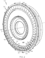
FIG. 2 is a perspective view of a compressor stage of the gas turbine engine ofFIG. 1 according to example embodiments; -
FIG. 3 is an axial cross section view of the compressor stage ofFIG. 2 according to example embodiments; -
FIG. 4 is an axial cross section view of a shroud of the compressor stage ofFIG. 3 ; and -
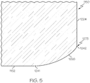
FIG. 5 is an axial cross section of the shroud according to additional embodiments of the present disclosure. - The following detailed description is merely exemplary in nature and is not intended to limit the present disclosure or the application and uses of the present disclosure. Furthermore, there is no intention to be bound by any theory presented in the preceding background or the following detailed description.
- The present disclosure provides a turbomachine, such as a compressor section for a gas turbine engine. The compressor section includes a rotor blade with an outer radial edge or blade tip that radially opposes a shroud. The shroud may include one or more casing treatments, such as one or more grooves that are recessed radially into the inner shroud surface. The groove(s), in at least one axial cross section of the compressor section, may be generally shaped to resemble a triangle, wedge, sawtooth, and/or serration.
- The casing treatment may also include smoothly blended transitions between the shroud surface and the internal surfaces of the groove. The transitions may be rounded and convexly contoured, similar to the profile of an external fillet. The dimensions of the contoured transitions and dimensional relationships of the transitions with respect to other areas of the shroud are controlled, tailored, and determined according to various considerations discussed below. Accordingly, the rotor tip and opposing shroud configuration are configured to provide a uniquely robust compressor section that provides high efficiency and operability throughout a wide range of operating conditions including "near-stall" conditions and conditions involving "rubbing" between the rotor blade and the shroud surface.
- Turning now to
FIG. 1 , a functional block diagram of an exemplarygas turbine engine 100 is depicted. Theengine 100 may be included on avehicle 110 of any suitable type, such as an aircraft, rotorcraft, marine vessel, train, or other vehicle, and theengine 100 can propel or provide auxiliary power to thevehicle 110. - In some embodiments, the depicted
engine 100 may be a single-spool turbo-shaft gas turbine propulsion engine; however, the exemplary embodiments discussed herein are not intended to be limited to this type, but rather may be readily adapted for use in other types of turbine engines including but not limited to two-spool engines, three-spool engines, turbofan and turboprop engines or other turbomachines. - The
engine 100 may generally include anintake section 101, acompressor section 102, acombustion section 104, aturbine section 106, and anexhaust section 108, which may be arranged along alongitudinal axis 103. A downstream direction through theengine 100 may be defined generally along theaxis 103 from theintake section 101 to theexhaust section 108. Conversely, an upstream direction is defined from theexhaust section 108 to theintake section 101. - The
intake section 101 may receive an intake airstream indicated byarrows 107 inFIG. 1 . Thecompressor section 102, may include one or more compressor stages that drawair 107 downstream into theengine 100 and compress theair 107 to raise its pressure. In the depicted embodiment, thecompressor section 102 includes two stages: a low-pressure compressor stage 112 and a high-pressure compressor stage 113. The compressor stages 112, 113 may be disposed sequentially along theaxis 103 with the low-pressure compressor stage 112 disposed upstream of the high-pressure compressor stage 113. It will be appreciated that theengine 100 could be configured with more or less than this number of compressor stages. - The compressed air from the
compressor section 102 may be directed into thecombustion section 104. In thecombustion section 104, which includes acombustor assembly 114, the compressed air is mixed with fuel supplied from a non-illustrated fuel source. The fuel- and-air mixture is combusted in thecombustion section 104, and the high energy combusted air mixture is then directed into theturbine section 106. - The
turbine section 106 includes one or more turbines. In the depicted embodiment, theturbine section 106 includes two turbines: a high-pressure turbine 116 and a low-pressure turbine 118. However, it will be appreciated that theengine 100 could be configured with more or less than this number of turbines. No matter the particular number, the combusted air mixture from thecombustion section 104 expands through eachturbine shaft 119. The combusted air mixture is then exhausted via theexhaust section 108. Thepower shaft 119 may be used to drive various devices within theengine 100 and/or within thevehicle 110. - Referring now to
FIG. 2 , thecompressor section 102 will be discussed in greater detail according to example embodiments of the present disclosure. Specifically, the high-pressure compressor stage 113 is shown as an example; however, it will be appreciated that the features described may be included in the low-pressure compressor stage 112. It will be appreciated thatFIG. 2 is merely an example and that thecompressor section 102 may vary from the illustrated embodiment without departing from the scope of the present disclosure. For example, the curvics shown inFIG. 2 are optional features. - The
compressor section 102 may include acase 120. Thecase 120 may be hollow and cylindrical in some embodiments. Thecase 120 may also include ashroud 150 with a shroud surface 152 (e.g., an inner diameter surface of the shroud 150). Theshroud surface 152 may define a downstream direction. - The
compressor section 102 may also include arotor 122. Therotor 122 may include adisk 124. Thedisk 124 may be supported on the shaft 119 (FIG. 1 ). Thedisk 124 may be centered on theaxis 103. Therotor 122 may further include a plurality ofblades 126, which extend radially from thedisk 124 and which may be spaced apart in a circumferential direction about theaxis 103. Theblades 126 of therotor 122 may radially oppose theshroud surface 152. Therotor 122, including thedisk 124 and the plurality ofblades 126, may rotate about the axis 103 (i.e., the axis of rotation) relative to thecase 120, theshroud 150, and theshroud surface 152 to generate an aft axial fluid flow (fluid flow in the downstream direction) through thecompressor section 102 as will be discussed. - An inner
radial end 130 of theblade 126 may be fixedly attached to the outer diameter of thedisk 124. Theblade 126 radially terminates at an outer radial edge orblade tip 132. Theblade tip 132 is radially spaced apart from the innerradial end 130. Theblade 126 further includes aleading edge 134, which extends radially between the innerradial end 130 and theblade tip 132. Furthermore, theblade 126 includes a trailingedge 136, which extends radially between the innerradial end 130 and theblade tip 132, and which is spaced downstream of theleading edge 134 relative to thelongitudinal axis 103. Theblade tip 132 extends between theleading edge 134 and the trailingedge 136 and extends generally along thelongitudinal axis 103. As shown inFIG. 2 , theblades 126 may exhibit complex, three-dimensional curved surfaces and may be shaped so as to have a degree of helical twist about its respective radial axis and/or sweeping curvature in the downstream direction. - Moreover, the
shroud 150 may include acasing treatment 154. Thecasing treatment 154 may be a feature included on theshroud surface 152. As will be discussed, thecasing treatment 154 may include one ormore grooves 156 that are recessed radially into theshroud surface 152. Thecasing treatment 154 is configured to resist a reverse axial fluid flow (i.e., fluid flow in the upstream direction) during near-stall operating conditions of thecompressor section 102. In other words, thecasing treatment 154 increases the stall margin of thecompressor section 102 and/or reduces a deficit in the axial fluid flow, especially proximate theleading edge 134. - Referring now to
FIG. 3 , additional features of thecompressor section 102 will be discussed. A longitudinal profile of theblade tip 132 is shown in relation to theshroud 150. InFIG. 3 , only half the axial cross-sectional view of thecompressor section 102 is shown; the other half may be substantially rotationally symmetric about the axis ofrotation 103. Additionally, certain aspects of theengine 100 may not be shown inFIG. 2 , or only schematically shown, for clarity in the relevant description of exemplary embodiments. One skilled in the art will understand thatFIG. 3 illustrates an example embodiment of thecompressor section 102, and that other features may be included and/or features may be different in other embodiments of the present disclosure. - The
leading edge 134 and the trailingedge 136 are also shown projected onto the plane of the cross section ofFIG. 3 . As shown, theblade tip 132 may include a forward end 164 (at the transition between theleading edge 134 and the blade tip 132) and an aft end 166 (at the transition between theblade tip 132 and the trailing edge 136). Theblade 126 may also define a blade tip chord length 162 (an axial chord length) that is measured parallel to thelongitudinal axis 103 from theforward end 164 to theaft end 166. - The
blade tip 132 may be curved in some embodiments between theforward end 164 and theaft end 166, as represented in the axial cross-section ofFIG. 3 . Theblade tip 132 may bow outward radially between theforward end 164 and theaft end 166 so as to define acrown area 160. In some embodiments, aradius 158 of the blade tip 132 (here, measured normal to thelongitudinal axis 103 from theaxis 103 to the blade tip 132) may be nonconstant. As such, the radius varies along thelongitudinal axis 103. Moving in the downstream direction, theradius 158 may gradually increase from theforward end 164 to thecrown area 160, and theradius 158 may gradually decrease from thecrown area 160 to theaft end 166 of theblade tip 132. Thus, thecrown area 160 may have thelargest radius 158 of theblade tip 132, and the profile of theblade tip 132 may contour convexly and continuously along thelongitudinal axis 103 from theleading edge 134 to the trailingedge 136. However, it will be appreciated that theblade tip 132 may have a different configuration from the illustrated crowned profile without departing from the scope of the present disclosure. In some alternative embodiments, for example, theradius 158 may remain substantially constant along at least part of theblade tip 132. - The
blade tip 132 may also, in some embodiments, be configured for a frustoconically shapedshroud surface 152. Theblade tip 132 may be curved (i.e., nonlinear) with dimensions that correspond to those of theshroud surface 152. Theblade tip 132 may be crowned and may bow outward between theforward end 164 and theaft end 166 so as to define thecrown area 160. - Furthermore, the
shroud 150 may be an annular component with theshroud surface 152 defined on an inner diameter thereof. Theshroud surface 152 may be centered about theaxis 103. Theshroud 150 may define ashroud radius 168 measured normal to theaxis 103, from theaxis 103 to theshroud surface 152. As illustrated inFIG. 3 , theshroud radius 168 may remain substantially constant along thelongitudinal axis 103 across a majority of theshroud surface 152. In other words, theshroud surface 152 may be substantially cylindrical with a constant shroud radius 168 (i.e., theshroud surface 152 may resemble a right circular cylinder). In other embodiments of the present disclosure, theshroud 150 may be frustoconic in shape and tapered such that theshroud radius 168 changes gradually along thelongitudinal axis 103. - A
clearance region 176 is defined between theblade tip 132 and the radially opposing region of theshroud surface 152. Clearance dimensions (measured radially between theshroud surface 152 and the blade tip 132) may vary along thelongitudinal axis 103 from theleading edge 134 to the trailingedge 136. Acrown clearance 172 is defined between thecrown area 160 and theshroud surface 152 and may represent the smallest clearance. A leadingclearance 170 is defined between theforward end 164 and theshroud surface 152, a trailingclearance 174 is defined between theaft end 166 and theshroud surface 152, and either may represent the largest clearance dimension between theblade tip 132 and theshroud surface 152. In additional embodiments, the maximum and minimum tip clearances may occur at any position between theforward end 164 and theaft end 166. Also, the minimum clearance of theclearance region 176 may be located approximately at a mid-chord position (i.e., half way between theforward end 164 and the aft end 166); however, this minimum clearance region may be disposed at any position between theforward end 164 and theaft end 166. - Accordingly, as shown in
FIG. 3 , theclearance region 176 may have a crowned or crown-like shape. In this case, theclearance region 176 is crowned because the amount of clearance gradually increases both upstream of thecrown area 160 and downstream of thecrown area 160. In some embodiments, thecrown clearance 172 may be between approximately forty percent (40%) to sixty percent (60%) of the leadingclearance 170 and/or forty percent (40%) to sixty percent (60%) of the trailingclearance 174. It will be appreciated that theclearance region 176 may be crowned when generally at the design operating condition of the compressor, which for an aircraft propulsion engine, may be a sea-level takeoff, cruise, and/or approach condition. - Rotation of the
rotor 122 about theaxis 103 generates aft axial fluid flow through theclearance region 176 in the downstream direction (i.e., in a direction from compressor inlet toward compressor outlet or, in other words, from left to right as shown inFIG. 3 ). In contrast, reverse axial flow refers to fluid flow generally in an opposite direction (from right to left inFIG. 3 ). Broken line 180 inFIG. 3 represents a flow axis for downstream flow through theclearance region 176. In the illustrated embodiment, the flow axis 180 is substantially parallel to the axis ofrotation 103; however, it will be appreciated that the flow axis 180 may be disposed at a positive angle relative to the axis of rotation 103 (e.g., in embodiments in which theshroud surface 152 is frustoconic in shape). It will be appreciated that this is a simplified representation of the flow mechanics through theclearance region 176. In reality, therotor 122 may generate aft flow with some flow through theclearance region 176 locally reversed. Features of the present disclosure may prevent and/or limit the reverse flow, thereby avoiding stall and/or surge conditions. - As mentioned above, the
shroud 150 may include acasing treatment 154. In some embodiments, thecasing treatment 154 includes agrooved section 210 with a plurality of grooves that are recessed radially into theshroud surface 152. In some embodiments, thegrooved section 210 may include afirst groove 211, asecond groove 212, athird groove 213, and afourth groove 214. The grooves 211-214 may be substantially similar to each other except as noted. It will be appreciated thatFIG. 3 illustrates example embodiments of thecasing treatment 154 and that other embodiments may differ without departing from the scope of the present disclosure. The grooves 211-214 may resist reverse axial fluid flow through theclearance region 176. Accordingly, the grooves 211-214 may improve operations throughout a wide range of conditions including "near-stall" conditions. - One or more of the grooves 211-214 may have a cross-sectional profile resembling a triangle, wedge, sawtooth, and/or serration. In some embodiments, the grooves 211-214 may substantially resemble a right triangle. Also, in some embodiments, the grooves 211-214 may be annular and may extend continuously about the
axis 103. Thus, these may be considered circumferential grooves 211-214 that are consistent and continuous about theaxis 103. - The grooves 211-214 may be spaced axially apart evenly along the
shroud surface 152, with thefirst groove 211 disposed in the forward-most position and thefourth groove 214 disposed in the aft-most position. At least one of the grooves 211-214 may be axially disposed to radially oppose theblade tip 132. For example, as shown inFIG. 3 , each of the grooves 211-214 is axially positioned to oppose theblade tip 132. Furthermore, in some embodiments, the grooves 211-214 may be axially positioned upstream of thecrown area 160 of theblade tip 132. - The
first groove 211 will be discussed in detail with reference toFIG. 4 , and it will be appreciated that the second, third, and fourth grooves 212-214 may include similar features. Abroken line 251 extends axially from an area of theshroud surface 152 immediately upstream of thegroove 211 to an area of theshroud surface 152 immediately downstream of thegroove 211 for reference purposes. As shown, thegroove 211 may include a leadingportion 220 and a trailingportion 222. - The leading
portion 220 may include aforward surface 224 that faces substantially in the downstream direction. As shown in the axial cross-section ofFIG. 4 , theforward surface 224 may be substantially flat and may be disposed substantially normal to the flow axis 180 and/or normal to the axis ofrotation 103. In other embodiments, theforward surface 224 may be disposed substantially normal to the flow axis 180 and may be disposed at non-normal angle relative to the axis of rotation 103 (e.g., in embodiments in which theshroud surface 152 is frustoconic in shape). In additional embodiments, theforward surface 224 may be within twenty degrees (20°) of a line tangent to crownarea 160 of theblade tip 132. - The leading
portion 220 may also include aforward transition 226. Theforward transition 226 may be convexly contoured (i.e., blended) between theshroud surface 152 disposed immediately upstream of thegroove 211 and theforward surface 224. In some embodiments, theforward transition 226 may define aradius 250. Theradius 250 may be substantially constant in some embodiments. However, in other embodiments, theradius 250 may be nonconstant. - The trailing
portion 222 may include ataper surface 228 that tapers inward radially as thetaper surface 228 extends in downstream direction. As shown in the axial cross-section ofFIG. 4 , thetaper surface 228 may be substantially flat and may be disposed at a positive angle (e.g., an acute angle) 232 relative to theforward surface 224. In some embodiments, theangle 232 may be at least forty-five degrees (45°). - The trailing
portion 222 may further include a trailingtransition 230. The trailingtransition 230 may be convexly contoured (i.e., blended) between thetaper surface 228 and theshroud surface 152 disposed immediately downstream of thegroove 211. As shown, the trailingtransition 230 may have a nonconstant radius; however, in other embodiments the trailingtransition 230 may have a constant radius. - As shown in the cross-section of
FIG. 4 , theforward transition 226 may intersect theshroud surface 152 at afirst intersection 241. Theforward transition 226 may intersect theforward surface 224 at asecond intersection 242. Theforward surface 224 may intersect thetaper surface 228 at athird intersection 243. Thetaper surface 228 may intersect the trailingtransition 230 at afourth intersection 244. The trailingtransition 230 may intersect theshroud surface 152 at afifth intersection 245. Furthermore, as shown inFIG. 4 , theforward surface 224 and theshroud surface 152 may define an imaginarysixth intersection 246. Likewise, thetaper surface 228 and theshroud surface 152 may define an imaginaryseventh intersection 247. - The trailing
transition 230 may be significantly more gradual than theforward transition 226. Stated differently, theforward transition 226 may be significantly more abrupt than the trailingtransition 230. Accordingly, benefit from thecasing treatment 154 may be provided for increasing the stall margin, and yet thecompressor section 102 may be highly robust if there is rubbing between theshroud 150 and theblade tip 132. - Referring now to
FIGS. 3 and4 , thegroove 211 may exhibit various dimensional relationships that make thecompressor section 102 highly robust. For example, theminimum radius 250 of theforward transition 226 may be significantly smaller than the minimum radius of the trailingtransition 230. In some embodiments, for example, theminimum radius 250 of theforward transition 226 may be at most two-fifths (2/5) of the minimum radius of the trailingtransition 230. - Dimensions of the
groove 211 may also be expressed in relation to the imaginary sixth andseventh intersections groove 211 may have agroove depth dimension 260 measured radially from thesixth intersection 246 to the third intersection 243 (i.e., measured radially from theshroud surface 152 to the third intersection 243). Thedepth dimension 260 may be between approximately three percent (3%) and twenty percent (20%) of the blade tip chord length 162. In some embodiments, thedepth dimension 260 may be between approximately five percent (5%) and fifteen percent (15%) of the blade tip chord length 162. Additionally, in some embodiments, thedepth dimension 260 may be approximately eight percent (8%) of the blade tip chord length 162. - Moreover, the
groove 211 may have agroove length dimension 262 measured axially from thesixth intersection 246 to theseventh intersection 247. Thegroove length dimension 262 may be between three percent (3%) and twenty percent (20%) of the blade tip chord length 162. In some embodiments, thelength dimension 262 may be between approximately six percent (6%) and eighteen percent (18%) of the blade tip chord length 162. Additionally, in some embodiments, thelength dimension 262 may be approximately nine percent (9%) of the blade tip chord length 162. - Furthermore, the
groove 211 may have a firsttaper length dimension 264 measured parallel to thetaper surface 228 from thethird intersection 243 to theseventh intersection 247. The firsttaper length dimension 264 may be between four percent (4%) and twenty-nine percent (29%) of the blade tip chord length 162. In some embodiments, the firsttaper length dimension 264 may be between approximately seven percent (7%) and twenty-four percent (24%) of the blade tip chord length 162. Also, in some embodiments, the firsttaper length dimension 264 may be approximately twelve percent (12%) of the blade tip chord length 162. - Additionally, the
groove 211 may have a secondtaper length dimension 266 measured parallel to thetaper surface 228 from thethird intersection 243 to thefourth intersection 244. The difference between the firsttaper length dimension 264 and the secondtaper length dimension 266 may be referred to as a thirdtaper length dimension 268. The thirdtaper length dimension 268 may be between approximately five percent (5%) and fifty-five percent (55%) of the firsttaper length dimension 264. In some embodiments, the thirdtaper length dimension 268 may be between approximately twenty percent (20%) and forty percent (40%) of the firsttaper length dimension 264. Also, in some embodiments, the thirdtaper length dimension 268 may be approximately thirty percent (30%) of the firsttaper length dimension 264. - A first axial distance 270 measured parallel to the
axis 103 between theseventh intersection 247 and thefifth intersection 245 may be between approximately five percent (5%) and fifty-five percent (55%) of the firsttaper length dimension 264. Also, the first axial distance 270 may be between approximately twenty percent (20%) and forty percent (40%) of the firsttaper length dimension 264. Also, in some embodiments, the first axial distance 270 may be approximately thirty percent (30%) of the firsttaper length dimension 264. - Furthermore, a second
axial distance 272 measured parallel to theaxis 103 between thefifth intersection 245 and the adjacent first intersection 241' of the neighboringsecond groove 212 may be greater than zero percent (0%) of thegroove length dimension 262. Also, the secondaxial distance 272 may be greater than five percent (5%) of thegroove length dimension 262. In some embodiments, the secondaxial distance 272 may be approximately ten percent (10%) of thegroove length dimension 262. - Moreover, a third axial distance 274 measured parallel to the
axis 103 between thefirst intersection 241 and thesixth intersection 246 may be between approximately five percent (5%) and fifty-five percent (55%) of the firsttaper length dimension 264. The third axial distance 274 may be approximately six percent (6%) and thirteen percent (13%) of the firsttaper length dimension 264. In some embodiments, the third axial distance 274 may be approximately ten percent (10%) of the firsttaper length dimension 264. - Also, a
radial distance 276 measured normal to theaxis 103 between thesixth intersection 246 and thesecond intersection 242 may be between approximately five percent (5%) and fifty-five percent (55%) of the firsttaper length dimension 264. Theradial distance 276 may be approximately six percent (6%) and thirteen percent (13%) of the firsttaper length dimension 264. In some embodiments, theradial distance 276 may be approximately ten percent (10%) of the firsttaper length dimension 264. - One or more dimensions of the grooves 211-214 may be determined according to the dimensions of the
gap clearance region 176. For example, the forward and/or trailingtransitions crown clearance 172 is smaller. This is because, with asmaller crown clearance 172, there is less likelihood of reverse axial fluid flow; therefore, thetransitions transitions crown clearance 172 is larger. This is because, with alarger crown clearance 172, there may be more likelihood of reverse axial fluid flow, and thetransitions - The
shroud 150 may be manufactured in various ways within the scope of the present disclosure. For example, theshroud 150 may be formed initially without the grooves 211-214, and then material may be removed from the shroud 150 (e.g., with one or more cutting tools) to form the grooves 211-214. In this embodiment, a lathe or lathe-like machine may be used for forming the grooves 211-214. Also, in this embodiment, theangle 232 may be formed according to the fillet radius of the cutting tool. The forward and trailingtransitions shroud 150 and cutting tool (e.g., with computerized machine controls). Additionally, in some embodiments, a template may be used for forming at least two of the grooves 211-214 concurrently. - In additional embodiments, the
shroud 150 may be formed with the grooves 211-214 included therein. Theshroud surface 152 and the grooves 211-214 may be formed concurrently in a single manufacturing process. For example, theshroud 150 and grooves 211-214 may be formed using an additive manufacturing process, such as 3-D printing. In these embodiments, theshroud 150 may be formed layer-by-layer along theaxis 103, beginning at the forward end and ending at the aft end. As such, theforward transition 226 andforward surface 224 may be formed before thetaper surface 228 and the trailingtransition 230, thereby ensuring that there is sufficient mechanical support for these features during the manufacturing process. - Furthermore, in the illustrated embodiments, the
casing treatment 154 may be integral to theshroud 150 and formed directly within the material of theshroud 150. However, in other embodiments, the grooves 211-214 may be formed on an arcuate insert pierce, which is then attached to an inner surface of a supporting piece of theshroud 150. Thus, theshroud 150 may be a unitary, monolithic, one-piece member, or theshroud 150 may be assembled from multiple pieces. - Additionally, the grooves 211-214 may be formed in abradable material of the
shroud 150. As such, the abradable material may be intended to wear away, for example, in the event of contact with theblade tip 132. However, the forward and/or trailingtransitions shroud 150. In these embodiments, the forward and/or trailingtransitions blade tip 132 is unlikely to be damaged. - Referring now to
FIG. 5 , additional embodiments of theshroud 1150 will be discussed. Theshroud 1150 may be substantially similar to theshroud 150 ofFIGS. 3 and4 except as noted. Components that correspond to those ofFIGS. 3 and4 are indicated with corresponding reference numbers increased by 1000. - The
forward transition 1226 is shown inFIG. 5 . The convex contoured shape of theforward transition 1226 at the first intersection 1241 (the external transition intersection) may be a continuous, gradual, and edgeless contoured transition from theshroud surface 1152. However, aslight edge 1273 or corner may remain at the second transition 1242 (the internal transition intersection) with theforward surface 1224 as shown inFIG. 5 . - Although not specifically shown, the configuration of
FIG. 5 may apply to the trailingtransition 230 as well. Specifically, the convex contoured shape of the trailingtransition 230 may cause the fifth transition 245 (the external transition intersection) to be continuous, gradual, and edgeless, whereas a slight edge or corner may remain at the fourth transition 244 (the internal transition intersection). - Accordingly, the
compressor section 102 may provide various advantages. For example, theclearance region 176 may be relatively small for increasing operating efficiency. A portion of the aft axial fluid flow generated by thecompressor section 102 may flow into the grooves 211-214 of thecasing treatment 154. Because the trailingtransitions 230 of the grooves 211-214 are gradual (i.e., they have relatively large radii), the flow into the grooves 211-214 is directed downstream and slightly inward radially such that there is relatively little drag or resistance to the flow in the downstream direction. Also, theforward surfaces 224 of the grooves 211-214 can effectively increase resistance to reverse axial fluid flow and increase the stall margin of thecompressor section 102. In addition, theshroud blade tip 132 and theshroud transitions blade tip 132. Accordingly, damage to theblade tip 132 and/or damage to theshroud - While at least one exemplary embodiment has been presented in the foregoing detailed description, it should be appreciated that a vast number of variations exist. It should also be appreciated that the exemplary embodiment or exemplary embodiments are only examples, and are not intended to limit the scope, applicability, or configuration of the present disclosure in any way. Rather, the foregoing detailed description will provide those skilled in the art with a convenient road map for implementing an exemplary embodiment of the present disclosure. It is understood that various changes may be made in the function and arrangement of elements described in an exemplary embodiment without departing from the scope of the present disclosure as set forth in the appended claims.
Claims (15)
- A compressor section of a gas turbine engine, the compressor section defining a downstream direction and an upstream direction, the compressor section comprising:a shroud with a shroud surface;a rotor rotatably supported within the shroud, the rotor including a blade that radially terminates at a blade tip, the blade tip opposing the shroud surface, the rotor configured to rotate within the shroud about an axis of rotation;a serration groove that is recessed into the shroud surface;
the serration groove including a forward portion with a forward transition and a forward surface that faces in the downstream direction, the forward transition being convexly contoured between the shroud surface and the forward surface; and
the serration groove including a trailing portion with a taper surface and a trailing transition, the taper surface tapering inward as the taper surface extends from the forward surface to the trailing transition, the trailing transition being convexly contoured between the taper surface and the shroud surface. - The compressor section of claim 1, wherein the forward surface and the taper surface are substantially flat; and/or
wherein the blade tip includes a forward end and an aft end, and the blade tip is curved between the forward end and the aft end. - The compressor section of claim 1, wherein:the forward transition intersects the shroud surface at a first intersection;the forward transition intersects the forward surface at a second intersection;the forward surface intersects the taper surface at a third intersection;the taper surface intersects the trailing transition at a fourth intersection;the trailing transition intersects the shroud surface at a fifth intersection;the forward surface and the shroud surface define an imaginary sixth intersection; andthe taper surface and the shroud surface define an imaginary seventh intersection.
- The compressor section of claim 3, wherein the forward portion has a first dimension measured from the first intersection to the sixth intersection;
wherein the trailing portion has a second dimension measured along the taper surface, the second dimension measured from the third intersection to the seventh intersection; and
wherein the first dimension is between approximately five percent (5%) and fifty-five percent (55%) of the second dimension. - The compressor section of claim 4, wherein the first dimension is between approximately six percent (6%) and thirteen percent (13%) of the second dimension.
- The compressor section of claim 3, wherein the trailing portion has a second dimension measured along the taper surface, the second dimension measured from the third intersection to the seventh intersection;
wherein the trailing portion has a third dimension measured along the taper surface, the third dimension measured from the fourth intersection to the seventh intersection; and
wherein the third dimension is between approximately five percent (5%) and fifty-five percent (55%) of the second dimension. - The compressor section of claim 6, wherein the third dimension is between approximately twenty percent (20%) and forty percent (40%) of the second dimension.
- The compressor section of claim 3, wherein the trailing portion has a second dimension measured along the taper surface, the second dimension measured from the third intersection to the seventh intersection;
wherein the blade tip defines a chord length dimension between a forward end and an aft end of the blade tip; and
wherein the second dimension is between approximately four percent (4%) and twenty-nine percent (29%) of the chord length dimension. - The compressor section of claim 3, wherein the trailing portion has a fourth dimension measured from the sixth intersection to the seventh intersection;
wherein the blade tip defines a chord length dimension between a forward end and an aft end of the blade tip; and
wherein the fourth dimension is between approximately three percent (3%) and twenty percent (20%) of the chord length dimension. - The compressor section of claim 1, wherein a minimum radius of the forward transition is, at most, two-fifths (2/5) the minimum radius of the trailing transition.
- The compressor section of claim 3, wherein the serration groove has a depth dimension measured radially from the sixth intersection to the third intersection;
wherein the blade tip defines a chord length dimension between a forward end and an aft end of the blade tip; and
wherein the depth dimension is between approximately five percent (5%) and fifteen percent (15%) of the chord length. - The compressor section of claim 3, wherein the trailing portion has a second dimension measured along the taper surface, the second dimension measured from the third intersection to the seventh intersection;
wherein the trailing portion has a fifth dimension measured axially from the seventh intersection to the fifth intersection; and
wherein the fifth dimension is between approximately twenty percent (20%) and forty percent (40%) of the second dimension. - The compressor section of claim 3, wherein the serration groove is a first serration groove of a plurality of serration grooves recessed into the shroud surface, the plurality of serration grooves including a second serration groove;
wherein the first serration groove defines a groove length dimension distance measured axially from the sixth intersection to the seventh intersection;
wherein the plurality of serration grooves defines a second axial distance measured axially between the fifth intersection of the first serration groove and the first intersection of the second serration groove;
wherein the second axial distance is greater than five percent (5%) of the groove length dimension. - The compressor section of claim 3, wherein at least one of the first intersection and the fifth intersection is continuous and gradual; and
wherein at least one of the second intersection and the fourth intersection include an edge. - A method of manufacturing a shroud of a gas turbine engine comprising:forming a shroud surface of the shroud, the shroud surface configured to oppose a blade tip of a rotor rotatably supported within the shroud, the shroud surface defining a downstream direction;forming a serration groove that is recessed into the shroud surface to include a forward portion with a forward transition and a forward surface that faces in the downstream direction, the forward transition being convexly contoured between the shroud surface and the forward surface, the serration groove including a trailing portion with a taper surface and a trailing transition, the taper surface tapering in an inward direction as the taper surface extends from the forward surface to the trailing transition, the trailing transition being convexly contoured between the taper surface and the shroud surface.
Applications Claiming Priority (1)
| Application Number | Priority Date | Filing Date | Title |
|---|---|---|---|
| US16/363,117 US11015465B2 (en) | 2019-03-25 | 2019-03-25 | Compressor section of gas turbine engine including shroud with serrated casing treatment |
Publications (2)
| Publication Number | Publication Date |
|---|---|
| EP3715640A1 true EP3715640A1 (en) | 2020-09-30 |
| EP3715640B1 EP3715640B1 (en) | 2024-01-24 |
Family
ID=69845288
Family Applications (1)
| Application Number | Title | Priority Date | Filing Date |
|---|---|---|---|
| EP20163779.0A Active EP3715640B1 (en) | 2019-03-25 | 2020-03-17 | Compressor section of gas turbine engine including shroud with serrated casing treatment |
Country Status (2)
| Country | Link |
|---|---|
| US (1) | US11015465B2 (en) |
| EP (1) | EP3715640B1 (en) |
Families Citing this family (1)
| Publication number | Priority date | Publication date | Assignee | Title |
|---|---|---|---|---|
| US20230151825A1 (en) * | 2021-11-17 | 2023-05-18 | Pratt & Whitney Canada Corp. | Compressor shroud with swept grooves |
Citations (4)
| Publication number | Priority date | Publication date | Assignee | Title |
|---|---|---|---|---|
| US4767266A (en) * | 1984-02-01 | 1988-08-30 | Societe Nationale D'etude Et De Construction De Moteurs D'aviation (Snecma) | Sealing ring for an axial compressor |
| US20080044273A1 (en) * | 2006-08-15 | 2008-02-21 | Syed Arif Khalid | Turbomachine with reduced leakage penalties in pressure change and efficiency |
| EP2141328A1 (en) * | 2008-07-03 | 2010-01-06 | Siemens Aktiengesellschaft | Sealing system between a shroud segment and a rotor blade tip and manufacturing method for such a segment |
| EP3361053A1 (en) * | 2017-02-14 | 2018-08-15 | Honeywell International Inc. | Grooved shroud casing treatment for high pressure compressor in a turbine engine |
Family Cites Families (16)
| Publication number | Priority date | Publication date | Assignee | Title |
|---|---|---|---|---|
| GB2017228B (en) * | 1977-07-14 | 1982-05-06 | Pratt & Witney Aircraft Of Can | Shroud for a turbine rotor |
| GB0526011D0 (en) | 2005-12-22 | 2006-02-01 | Rolls Royce Plc | Fan or compressor casing |
| GB0600532D0 (en) | 2006-01-12 | 2006-02-22 | Rolls Royce Plc | A blade and rotor arrangement |
| DE102008031982A1 (en) * | 2008-07-07 | 2010-01-14 | Rolls-Royce Deutschland Ltd & Co Kg | Turbomachine with groove at a trough of a blade end |
| US8439634B1 (en) * | 2011-01-21 | 2013-05-14 | Florida Turbine Technologies, Inc. | BOAS with cooled sinusoidal shaped grooves |
| FR2995949B1 (en) | 2012-09-25 | 2018-05-25 | Safran Aircraft Engines | TURBOMACHINE HOUSING |
| US8857943B2 (en) | 2013-03-15 | 2014-10-14 | Premier Print & Services Group, Inc. | Duplex printer with movable print head |
| US9644639B2 (en) | 2014-01-27 | 2017-05-09 | Pratt & Whitney Canada Corp. | Shroud treatment for a centrifugal compressor |
| JP6344735B2 (en) * | 2014-01-30 | 2018-06-20 | 三菱重工業株式会社 | Seal structure and rotating machine |
| US10309243B2 (en) * | 2014-05-23 | 2019-06-04 | United Technologies Corporation | Grooved blade outer air seals |
| US10465716B2 (en) * | 2014-08-08 | 2019-11-05 | Pratt & Whitney Canada Corp. | Compressor casing |
| JP6576466B2 (en) * | 2015-04-15 | 2019-09-18 | ローベルト ボツシユ ゲゼルシヤフト ミツト ベシユレンクテル ハフツングRobert Bosch Gmbh | Free tip axial fan assembly |
| JP6421091B2 (en) | 2015-07-30 | 2018-11-07 | 三菱日立パワーシステムズ株式会社 | Axial flow compressor, gas turbine including the same, and stationary blade of axial flow compressor |
| US10648346B2 (en) * | 2016-07-06 | 2020-05-12 | General Electric Company | Shroud configurations for turbine rotor blades |
| US10830082B2 (en) * | 2017-05-10 | 2020-11-10 | General Electric Company | Systems including rotor blade tips and circumferentially grooved shrouds |
| US10644630B2 (en) * | 2017-11-28 | 2020-05-05 | General Electric Company | Turbomachine with an electric machine assembly and method for operation |
-
2019
- 2019-03-25 US US16/363,117 patent/US11015465B2/en active Active
-
2020
- 2020-03-17 EP EP20163779.0A patent/EP3715640B1/en active Active
Patent Citations (4)
| Publication number | Priority date | Publication date | Assignee | Title |
|---|---|---|---|---|
| US4767266A (en) * | 1984-02-01 | 1988-08-30 | Societe Nationale D'etude Et De Construction De Moteurs D'aviation (Snecma) | Sealing ring for an axial compressor |
| US20080044273A1 (en) * | 2006-08-15 | 2008-02-21 | Syed Arif Khalid | Turbomachine with reduced leakage penalties in pressure change and efficiency |
| EP2141328A1 (en) * | 2008-07-03 | 2010-01-06 | Siemens Aktiengesellschaft | Sealing system between a shroud segment and a rotor blade tip and manufacturing method for such a segment |
| EP3361053A1 (en) * | 2017-02-14 | 2018-08-15 | Honeywell International Inc. | Grooved shroud casing treatment for high pressure compressor in a turbine engine |
Also Published As
| Publication number | Publication date |
|---|---|
| US20200308970A1 (en) | 2020-10-01 |
| EP3715640B1 (en) | 2024-01-24 |
| US11015465B2 (en) | 2021-05-25 |
Similar Documents
| Publication | Publication Date | Title |
|---|---|---|
| US9869186B2 (en) | Gas turbine engine component with compound cusp cooling configuration | |
| CA2789467C (en) | Non axis-symmetric stator vane endwall contour | |
| CA2697121C (en) | Intentionally mistuned integrally bladed rotor | |
| US10458427B2 (en) | Compressor aerofoil | |
| CA2705622C (en) | Rotor casing treatment with recessed baffles | |
| US9879544B2 (en) | Turbine rotor blades with improved tip portion cooling holes | |
| JP5450997B2 (en) | Rotor blade | |
| EP2971553B1 (en) | Rotor blade with a conic spline fillet at an intersection between a platform and a neck | |
| US11421544B2 (en) | Compressor section of gas turbine engine including hybrid shroud with casing treatment and abradable section | |
| EP3392459A1 (en) | Compressor blades | |
| US11143048B2 (en) | Labyrinth seal with variable tooth heights | |
| EP3715640B1 (en) | Compressor section of gas turbine engine including shroud with serrated casing treatment | |
| EP3456919B1 (en) | Rotor, corresponding gas turbine engine and method of forming a rotor | |
| EP3095959A1 (en) | Rotary blade designing and manufacturing method | |
| US20180128118A1 (en) | Turbine airfoil attachment with multi-radial serration profile | |
| CN110700897A (en) | Blade for a gas turbine engine | |
| CN113389599B (en) | Turbine engine with high acceleration and low blade turning airfoils | |
| GB2543327A (en) | Aerofoil tip profiles | |
| CA3197724A1 (en) | Method of manufacturing a mistuned rotor |
Legal Events
| Date | Code | Title | Description |
|---|---|---|---|
| PUAI | Public reference made under article 153(3) epc to a published international application that has entered the european phase |
Free format text: ORIGINAL CODE: 0009012 |
|
| STAA | Information on the status of an ep patent application or granted ep patent |
Free format text: STATUS: THE APPLICATION HAS BEEN PUBLISHED |
|
| AK | Designated contracting states |
Kind code of ref document: A1 Designated state(s): AL AT BE BG CH CY CZ DE DK EE ES FI FR GB GR HR HU IE IS IT LI LT LU LV MC MK MT NL NO PL PT RO RS SE SI SK SM TR |
|
| AX | Request for extension of the european patent |
Extension state: BA ME |
|
| STAA | Information on the status of an ep patent application or granted ep patent |
Free format text: STATUS: REQUEST FOR EXAMINATION WAS MADE |
|
| 17P | Request for examination filed |
Effective date: 20210315 |
|
| RBV | Designated contracting states (corrected) |
Designated state(s): AL AT BE BG CH CY CZ DE DK EE ES FI FR GB GR HR HU IE IS IT LI LT LU LV MC MK MT NL NO PL PT RO RS SE SI SK SM TR |
|
| STAA | Information on the status of an ep patent application or granted ep patent |
Free format text: STATUS: EXAMINATION IS IN PROGRESS |
|
| 17Q | First examination report despatched |
Effective date: 20211215 |
|
| RAP3 | Party data changed (applicant data changed or rights of an application transferred) |
Owner name: HONEYWELL INTERNATIONAL INC. |
|
| P01 | Opt-out of the competence of the unified patent court (upc) registered |
Effective date: 20230421 |
|
| GRAP | Despatch of communication of intention to grant a patent |
Free format text: ORIGINAL CODE: EPIDOSNIGR1 |
|
| STAA | Information on the status of an ep patent application or granted ep patent |
Free format text: STATUS: GRANT OF PATENT IS INTENDED |
|
| INTG | Intention to grant announced |
Effective date: 20230905 |
|
| GRAS | Grant fee paid |
Free format text: ORIGINAL CODE: EPIDOSNIGR3 |
|
| GRAA | (expected) grant |
Free format text: ORIGINAL CODE: 0009210 |
|
| STAA | Information on the status of an ep patent application or granted ep patent |
Free format text: STATUS: THE PATENT HAS BEEN GRANTED |
|
| AK | Designated contracting states |
Kind code of ref document: B1 Designated state(s): AL AT BE BG CH CY CZ DE DK EE ES FI FR GB GR HR HU IE IS IT LI LT LU LV MC MK MT NL NO PL PT RO RS SE SI SK SM TR |
|
| REG | Reference to a national code |
Ref country code: GB Ref legal event code: FG4D |
|
| REG | Reference to a national code |
Ref country code: CH Ref legal event code: EP |
|
| REG | Reference to a national code |
Ref country code: DE Ref legal event code: R096 Ref document number: 602020024683 Country of ref document: DE |
|
| REG | Reference to a national code |
Ref country code: IE Ref legal event code: FG4D |