EP3715592B1 - Gasturbinenmotorwartungsstand und zugehöriges verfahren zum warten eines gasturbinenmotors - Google Patents
Gasturbinenmotorwartungsstand und zugehöriges verfahren zum warten eines gasturbinenmotors Download PDFInfo
- Publication number
- EP3715592B1 EP3715592B1 EP20162598.5A EP20162598A EP3715592B1 EP 3715592 B1 EP3715592 B1 EP 3715592B1 EP 20162598 A EP20162598 A EP 20162598A EP 3715592 B1 EP3715592 B1 EP 3715592B1
- Authority
- EP
- European Patent Office
- Prior art keywords
- gas turbine
- engine
- turbine engine
- module
- flat
- Prior art date
- Legal status (The legal status is an assumption and is not a legal conclusion. Google has not performed a legal analysis and makes no representation as to the accuracy of the status listed.)
- Active
Links
Images








Classifications
-
- F—MECHANICAL ENGINEERING; LIGHTING; HEATING; WEAPONS; BLASTING
- F01—MACHINES OR ENGINES IN GENERAL; ENGINE PLANTS IN GENERAL; STEAM ENGINES
- F01D—NON-POSITIVE DISPLACEMENT MACHINES OR ENGINES, e.g. STEAM TURBINES
- F01D25/00—Component parts, details, or accessories, not provided for in, or of interest apart from, other groups
- F01D25/28—Supporting or mounting arrangements, e.g. for turbine casing
- F01D25/285—Temporary support structures, e.g. for testing, assembling, installing, repairing; Assembly methods using such structures
-
- F—MECHANICAL ENGINEERING; LIGHTING; HEATING; WEAPONS; BLASTING
- F02—COMBUSTION ENGINES; HOT-GAS OR COMBUSTION-PRODUCT ENGINE PLANTS
- F02C—GAS-TURBINE PLANTS; AIR INTAKES FOR JET-PROPULSION PLANTS; CONTROLLING FUEL SUPPLY IN AIR-BREATHING JET-PROPULSION PLANTS
- F02C7/00—Features, components parts, details or accessories, not provided for in, or of interest apart form groups F02C1/00 - F02C6/00; Air intakes for jet-propulsion plants
- F02C7/20—Mounting or supporting of plant; Accommodating heat expansion or creep
-
- B—PERFORMING OPERATIONS; TRANSPORTING
- B64—AIRCRAFT; AVIATION; COSMONAUTICS
- B64F—GROUND OR AIRCRAFT-CARRIER-DECK INSTALLATIONS SPECIALLY ADAPTED FOR USE IN CONNECTION WITH AIRCRAFT; DESIGNING, MANUFACTURING, ASSEMBLING, CLEANING, MAINTAINING OR REPAIRING AIRCRAFT, NOT OTHERWISE PROVIDED FOR; HANDLING, TRANSPORTING, TESTING OR INSPECTING AIRCRAFT COMPONENTS, NOT OTHERWISE PROVIDED FOR
- B64F5/00—Designing, manufacturing, assembling, cleaning, maintaining or repairing aircraft, not otherwise provided for; Handling, transporting, testing or inspecting aircraft components, not otherwise provided for
- B64F5/50—Handling or transporting aircraft components
-
- F—MECHANICAL ENGINEERING; LIGHTING; HEATING; WEAPONS; BLASTING
- F05—INDEXING SCHEMES RELATING TO ENGINES OR PUMPS IN VARIOUS SUBCLASSES OF CLASSES F01-F04
- F05D—INDEXING SCHEME FOR ASPECTS RELATING TO NON-POSITIVE-DISPLACEMENT MACHINES OR ENGINES, GAS-TURBINES OR JET-PROPULSION PLANTS
- F05D2220/00—Application
- F05D2220/30—Application in turbines
- F05D2220/32—Application in turbines in gas turbines
- F05D2220/323—Application in turbines in gas turbines for aircraft propulsion, e.g. jet engines
-
- F—MECHANICAL ENGINEERING; LIGHTING; HEATING; WEAPONS; BLASTING
- F05—INDEXING SCHEMES RELATING TO ENGINES OR PUMPS IN VARIOUS SUBCLASSES OF CLASSES F01-F04
- F05D—INDEXING SCHEME FOR ASPECTS RELATING TO NON-POSITIVE-DISPLACEMENT MACHINES OR ENGINES, GAS-TURBINES OR JET-PROPULSION PLANTS
- F05D2230/00—Manufacture
- F05D2230/60—Assembly methods
- F05D2230/68—Assembly methods using auxiliary equipment for lifting or holding
-
- F—MECHANICAL ENGINEERING; LIGHTING; HEATING; WEAPONS; BLASTING
- F05—INDEXING SCHEMES RELATING TO ENGINES OR PUMPS IN VARIOUS SUBCLASSES OF CLASSES F01-F04
- F05D—INDEXING SCHEME FOR ASPECTS RELATING TO NON-POSITIVE-DISPLACEMENT MACHINES OR ENGINES, GAS-TURBINES OR JET-PROPULSION PLANTS
- F05D2230/00—Manufacture
- F05D2230/70—Disassembly methods
-
- F—MECHANICAL ENGINEERING; LIGHTING; HEATING; WEAPONS; BLASTING
- F05—INDEXING SCHEMES RELATING TO ENGINES OR PUMPS IN VARIOUS SUBCLASSES OF CLASSES F01-F04
- F05D—INDEXING SCHEME FOR ASPECTS RELATING TO NON-POSITIVE-DISPLACEMENT MACHINES OR ENGINES, GAS-TURBINES OR JET-PROPULSION PLANTS
- F05D2230/00—Manufacture
- F05D2230/72—Maintenance
-
- F—MECHANICAL ENGINEERING; LIGHTING; HEATING; WEAPONS; BLASTING
- F05—INDEXING SCHEMES RELATING TO ENGINES OR PUMPS IN VARIOUS SUBCLASSES OF CLASSES F01-F04
- F05D—INDEXING SCHEME FOR ASPECTS RELATING TO NON-POSITIVE-DISPLACEMENT MACHINES OR ENGINES, GAS-TURBINES OR JET-PROPULSION PLANTS
- F05D2260/00—Function
- F05D2260/02—Transport and handling during maintenance and repair
-
- F—MECHANICAL ENGINEERING; LIGHTING; HEATING; WEAPONS; BLASTING
- F05—INDEXING SCHEMES RELATING TO ENGINES OR PUMPS IN VARIOUS SUBCLASSES OF CLASSES F01-F04
- F05D—INDEXING SCHEME FOR ASPECTS RELATING TO NON-POSITIVE-DISPLACEMENT MACHINES OR ENGINES, GAS-TURBINES OR JET-PROPULSION PLANTS
- F05D2260/00—Function
- F05D2260/40—Transmission of power
- F05D2260/403—Transmission of power through the shape of the drive components
- F05D2260/4031—Transmission of power through the shape of the drive components as in toothed gearing
- F05D2260/40311—Transmission of power through the shape of the drive components as in toothed gearing of the epicyclical, planetary or differential type
Definitions
- the present disclosure concerns a flat-packable gas turbine engine maintenance stand that is useful for disassembling and reassembling modules of a gas turbine engine in order to maintain the gas turbine engine for safety and performance purposes.
- Gas turbine engines are typically bulky machines weighing several thousand kilograms that need to be installed onto aircraft to power the aircraft and occasionally removed for maintenance and repair. Such engines generally comprise modules and maintenance and repair operations typically involve at least some measure of disassembling and reassembly those modules.
- United States patent application US 2018/0311808 A1 discloses an engine assembly stand that comprises two parallel posts, a horizontal girder which connects the tops of the posts and is vertically movable, and a suspension frame which can be displaced along the movable girder in a lateral direction and is further suitable for turning the engine mounted thereon about the main axes.
- GB 2509230 A discloses a gas turbine engine stand that comprises an engine frame and a base frame.
- the base frame has a slide rail to enable axial translation of the engine frame relative to the base frame.
- a load transfer arrangement engages with a part of the engine frame and slidingly engages with the slide rail.
- the gas turbine engine stand is used, inter alia, for splitting a core engine from a fan case.
- Gas turbine engine maintenance stands and related ground support equipment need to be available where the maintenance needs to be conducted. This can be at or near airports anywhere in the world. Gas turbine engines stands are typically bulky and heavy so transporting them to their desired locations can be onerous. Transportation by sea or land, more typically a combination of both, are options but they are generally time consuming and require specialist equipment and facilities throughout the transportation, often at various locations along the journey. Transportation by air would be potentially less time consuming but known gas turbine stands are typically too bulky for such transportation. Cargo or freight aircraft is available for transporting large and heavy cargo by air but the cost of acquiring or hiring such aircraft is generally prohibitive, and the use of such large aircraft is simply not possible at many airports. Known gas turbine engine maintenance stands could be disassembled for more convenient transportation and reassembled at their desired destination but that would be time consuming and require intense efforts by specialist engineering staff before and after the journey to the desired destination.
- the present invention provides a flat-packable gas turbine engine maintenance according to claim 1, and a method of disassembling a gas turbine according to claim 10, and a kit or parts, as set out in the appended claims.
- a flat-packable gas turbine engine maintenance stand for a gas turbine engine that comprises detachable modules including an engine core module that houses a high pressure compressor and a turbine module that houses a low pressure turbine
- the flat-packable gas turbine engine maintenance stand comprising: a pair of base beams, each base beam having a first end, a midsection and a second end; an engine core module support that straddles the pair of base beams at their midsection, the engine core module support having engine core module support arms that are configured to engage opposing sides of the engine core module of the gas turbine engine; and a turbine module support that straddles the pair of base beams adjacent their second ends, the turbine module support having turbine module support arms that are configured to engage opposing sides of the turbine module of the gas turbine engine; wherein each engine core module support arm is braced against one of the base beams by one or more structural support members; and the engine core module support has a mid-portion that connects each engine core module support arm and each engine core module support
- each engine core module support arm has an engine core module grip assembly that is configured to securably engage the engine core module of the gas turbine engine.
- the turbine module support includes at least one hinge e.g. for reducing torsion when connecting the turbine module support to the turbine module.
- each turbine module support arm has a turbine module grip assembly that is configured to securably engage the turbine module of the gas turbine engine.
- the turbine module support is detachable from the stand.
- each base beam has a plurality of wheel assemblies.
- the engine core module to be engaged by the engine core module support also houses or detachably includes one or more of a low pressure compressor and an intermediate pressure compressor.
- the turbine module to be engaged by the turbine module support also houses or detachably includes an intermediate pressure turbine.
- the engine core module to be engaged by the engine core module support or the turbine module to be engaged by the turbine module support also houses or detachably includes a high pressure turbine.
- a method of maintaining a gas turbine engine of an aircraft comprising the steps of: positioning a flat-packable gas turbine engine maintenance stand of the first aspect under the gas turbine engine to be maintained; moving the gas turbine engine from the aircraft onto the flat-packable gas turbine engine maintenance stand; detachably engaging the engine core module support arms of the flat-packable_gas turbine engine maintenance stand to the engine core module of the gas turbine engine; detachably engaging the turbine module support arms of the flat-packable_gas turbine engine maintenance stand to the turbine module of the gas turbine engine; removing one or more modules of the gas turbine engine whilst supporting the engine core module in the flat-packable_gas turbine engine maintenance stand; reassembling the gas turbine engine once maintenance is complete; detaching the engine core module support arms and the turbine module support arms from the gas turbine engine; and returning the gas turbine engine back onto the aircraft.
- kit of parts comprising a pair of base beams, an engine core module support; and a turbine module support, the kit forming a flat-packable gas turbine engine maintenance stand of the first aspect.
- the kit of parts may be flat-packed in a storage container.
- a gas turbine engine is generally indicated at 100, having a principal and rotational axis A-A.
- the gas turbine engine 100 comprises, in axial flow series, an air intake 102, a propulsive fan 104, an intermediate pressure compressor 106, a high pressure compressor 108, combustion equipment 110, a high pressure turbine 112, an intermediate pressure turbine 114, a low pressure turbine 116 and a engine core exhaust nozzle 118.
- a nacelle 120 generally surrounds the gas turbine engine 100 and defines the air intake 102, a bypass duct 122 and a bypass exhaust nozzle 124.
- a row of guide vanes 126 is positioned in the bypass duct 122 rearward of the propulsive fan 104.
- air entering the air intake 102 is accelerated by the propulsive fan 104 to produce two air flows: a first air flow "A1" into the intermediate pressure compressor 106 and a second air flow "A2" which passes through the bypass duct 122 to provide propulsive thrust.
- the intermediate pressure compressor 106 compresses the air flow directed into it before delivering that air to the high pressure compressor 108 where further compression takes place.
- the compressed air exhausted from the high pressure compressor 108 is directed into the combustion equipment 110 where it is mixed with fuel and the mixture combusted.
- the resultant hot combustion products then expand through, and thereby drive the high, intermediate and low pressure turbines 112, 114, 116 before being exhausted through the engine core exhaust nozzle 118 to provide additional propulsive thrust.
- the high, intermediate and low pressure turbines 112, 114, 116 drive respectively the high pressure compressor 108, the intermediate pressure compressor 106 and the propulsive fan 104, each by suitable interconnecting shaft and/or gear train.
- the gas turbine engine 100 further includes an engine core 128 and a fan case 130.
- the engine core 128 typically includes or houses various components, such as the intermediate pressure compressor 106, the high pressure compressor 108, the combustion equipment 110, the high pressure turbine 112, the intermediate pressure turbine 114, the low pressure turbine 116 and the engine core exhaust nozzle 118.
- the engine core 128 further includes an engine casing 132 for at least partially enclosing certain components of the engine core 128.
- the fan case 130 is disposed around the engine core 128.
- the fan case 130 surrounds the propulsive fan 104 and the guide vanes 126.
- the fan case 130 is coupled to the engine core 128 and/or the nacelle 120 by various methods, such as fasteners (e.g., bolts), welding, brazing, and so forth.
- Gas turbine engines are typically formed from detachable modules that house certain components of the aforementioned components.
- the gas turbine engine 100 illustrated in Figure 1 is exemplary in nature.
- Other gas turbine engines to which the present disclosure may be applied may have alternative configurations.
- such engines may have an alternative number of interconnecting shafts (e.g. two) and/or an alternative number of compressors and/or turbines.
- the engine may comprise a gearbox provided in a drive train from a turbine to a compressor and/or fan.
- the gearbox may be arranged to be driven by the core shaft that is configured to rotate (for example in use) at the lowest rotational speed (for example the first core shaft in the example above).
- the gearbox may be arranged to be driven only by the core shaft that is configured to rotate (for example in use) at the lowest rotational speed (for example only be the first core shaft, and not the second core shaft, in the example above).
- the gearbox may be arranged to be driven by any one or more shafts, for example the first and/or second shafts in the example above.
- the gearbox may be a reduction gearbox (in that the output to the fan is a lower rotational rate than the input from the core shaft). Any type of gearbox may be used.
- the gearbox may be a "planetary" or "star” gearbox, as described in more detail elsewhere herein.
- the gearbox may have any desired reduction ratio (defined as the rotational speed of the input shaft divided by the rotational speed of the output shaft), for example greater than 2.5, for example in the range of from 3 to 4.2, for example on the order of or at least 3, 3.1, 3.2, 3.3, 3.4, 3.5, 3.6, 3.7, 3.8, 3.9, 4, 4.1 or 4.2.
- the gear ratio may be, for example, between any two of the values in the previous sentence.
- a higher gear ratio may be more suited to "planetary" style gearbox. In some arrangements, the gear ratio may be outside these ranges.
- the gas turbine engine 100 is typically assembled in sections and these sections are then assembled to form the gas turbine engine 100.
- the engine core 128 and the fan case 130 are assembled separately and then connected to each other.
- the fan case 130 is generally coaxially disposed around the engine core 128.
- the engine core 128 and the fan case 130 may be coaxially disposed about the axis A-A. Correct alignment between the engine core 128 and the fan case 130 may be required before the engine core 128 and the fan case 130 are moved proximal to each other and connected.
- FIG 2 is a perspective view of a first embodiment of a flat-packable gas turbine engine maintenance stand 200 of the present disclosure in its erected configuration.
- the flat-packable gas turbine engine maintenance stand is suitable for use in maintaining a gas turbine engine that comprises detachable modules including an engine core module 140 and a turbine module 150.
- the composition of the engine core module 140 and the turbine module 150 can depend on the gas turbine engine concerned, however for present purposes the engine core module 140 houses a high pressure compressor and the turbine module 150 houses a low pressure turbine.
- the combustion equipment may be housed within the engine core module or within the turbine module or it may be separately detachable to the engine core module and/or the turbine module.
- the gas turbine engine may include other modules such as an intake module and a fan case module.
- the flat-packable gas turbine engine maintenance stand 200 has a pair of base beams 205. Each of these base beams has a first end 210, a midsection 215 and a second end 220. In the embodiment shown the base beams are substantially parallel however in other embodiments the base beams are non-parallel. For example, in some embodiments the base beams may diverge with respect to a central axis e.g. with the distance between the first ends being greater than the distance between the second ends to accommodate the dimensions of the gas turbine engine to be maintained. In some embodiments the stand may be configured so that the orientation of the base beams can be adjusted to accommodate the dimensions of a variety of gas turbine engines. In some embodiments one or more additional base beams may be provided to enhance the robustness of the stand.
- the flat-packable gas turbine engine maintenance stand 200 has an engine core module support 225 that straddles the pair of base beams 205 at their midsection 215, although not necessarily at their midpoint.
- the engine core module support 225 is connected to the base beams 205 by any suitable manner for the purpose, for example detachable clamps.
- the engine core module support 225 can take a variety of forms to fulfil the purpose of supporting the core module of the gas turbine engine to be maintained during the desired maintenance, disassembly and reassembly procedures.
- the engine core module support 225 has engine core module support arms 230, e.g. a pair of engine core module support arms 230, which are configured to engage opposing sides of the engine core module 140 of the gas turbine engine.
- Each engine core module support arm 230 may be provided with an engine core module grip assembly 235 that is formed to securably engage with the engine core module 140.
- the engine core module grip assembly may be provided in a variety of suitable forms, which may be specific to the type of gas turbine engine being maintained.
- the engine core module grip assembly may, for example comprise a trunnion and a trunnion and a trunnion support.
- structural support members 237 are provided to support the engine core module support arms 230 with respect to the engine core module support 225 and/or the base beams 205.
- the flat-packable gas turbine engine maintenance stand 200 has a turbine module support 240 that straddles the pair of base beams 205 adjacent their second ends 220.
- the turbine module support 240 can take a variety of forms to fulfil the purpose of supporting the turbine module 150 of the gas turbine engine to be maintained during the desired maintenance, disassembly and reassembly procedures. It may be detachable from the stand, for example when it is not required during the process of disassembling or reassembling a gas turbine engine or indeed when its presence may hinder the removal of certain modules from the engine.
- the turbine module support 240 has turbine module support arms 245, e.g. a pair of turbine module support arms 245, which are configured to engage opposing sides of the turbine module 150 of the gas turbine engine.
- Each turbine module support arm 245 may be provided with a turbine module grip assembly 250 that is formed to securably engage with the turbine module.
- the turbine module houses a low pressure turbine but it may also house an intermediate pressure turbine and/or a high pressure turbine depending on the construction of the gas turbine engine concerned. In the gas turbine engine shown, the turbine module houses a low pressure turbine and an intermediate pressure turbine.
- the turbine module grip assembly 250 may be provided in a variety of suitable forms, which may be specific to the type of gas turbine engine being maintained.
- the turbine module grip assembly may, for example comprise a trunnion and a trunnion and a trunnion support.
- the turbine module support 240 may include hinges 252 to reduce torsion when connecting the turbine module support 240 to the turbine module of the engine.
- the turbine module support 240 includes a balance beam with a turbine module support arm 245 pivotably connected at each end.
- the flat-packable gas turbine engine maintenance stand 200 may be provided with a set of wheel assemblies 260 for transporting the stand 200 to the gas turbine engine 100 for maintenance.
- the wheel assemblies 260 may be provided in a variety of suitable forms and at a variety of suitable locations on the stand 200. In the embodiment shown wheel assemblies 260 is provided at the first end 210 and the second end 220 of each of the base beams 205. The wheel assemblies 260 may be lockable so the stand can be kept in place as and when needed for that.
- the flat-packable gas turbine engine maintenance stand 200 may be mounted on a suitable trolley or other means for transporting the stand 200 to the engine.
- the gas turbine engine 100 to be maintained can be secured, e.g. bootstrapped, directly from the aircraft into the stand 200. No units are required to be removed to facilitate the use of the stand.
- the stand 200 is manoeuvred into position underwing the gas turbine engine 100 to be maintained and the engine is then lowered into and onto the stand using suitable equipment for that purpose. This procedure can be completed with the air intake module still fitted.
- Figure 3A is a side view that depicts how the flat-packable gas turbine engine maintenance stand of the first embodiment in its erected configuration is moved into position from behind a gas turbine engine that is due for maintenance. The engine and the stand are then ready for certain modules of the engine to be disassembled.
- the engine core module 140 houses or detachably includes a low pressure compressor, an intermediate pressure compressor, a high pressure compressor, and a high pressure turbine.
- the turbine module 150 houses or detachably includes an intermediate pressure turbine and a low pressure turbine.
- Figure 3B is an end view of the gas turbine engine with the first embodiment of the flat-packable gas turbine engine maintenance stand of the present disclosure located into position under it and supporting it in preparation for maintaining the gas turbine engine.
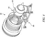
- Figure 4 is a perspective view of the flat-packable gas turbine engine maintenance stand 200 of the present disclosure supporting the gas turbine engine that is due for maintenance. Sequence of operations from this point varies depending on what work scope is required for the gas turbine. For present descriptive purposes the fan case 130 is the first part removed. It is not necessary to remove the intake module however .several of the figures that follow show the intake has been removed.
- the flat-packable gas turbine engine maintenance stand 200 of the present disclosure is used to disassemble a gas turbine engine at a modular level for conduct maintenance activities, it should be noted that a useful feature of the stand is that it can be stored and transported in a collapsed or disassembled configuration or condition. Indeed the stand may be flat-packed for convenient, space-efficient and cost-efficient storage and transportation.
- Figure 5 is a perspective view of the first embodiment of the flat-packable gas turbine engine maintenance stand of the present disclosure in its disassembled and flat-packable configuration.
- Cargo freight shipping on main deck is often expensive and reliance on shipping will have significant impact delivery commitments especially with respect to route frequency and destination.
- the flat-packable gas turbine engine maintenance stand 200 of the present disclosure being readily disassembleable, enables the stand to be readily transportable by rail, road or even by air.
- a flat-packed turbine engine maintenance stand 200 of the present disclosure may for example be stored within the lower hold of a passenger carrying aircraft. Once the stand has been delivered to the required location it can be built up with minimal infrastructure e.g. two spanners and two sockets.
- the flat-packable gas turbine engine maintenance stand 200 of the present disclosure can be used to disassemble a gas turbine engine module by module to conduct maintenance, more particularly, as an example, beginning with removing the fan case from the engine.
- a fan case dolly is connected to the fan case to support the fan case for removal.
- Fan case dollies are commercially available or can be constructed for the purpose using known methods.
- Figure 6 is a perspective view of the fan case 130 of the gas turbine engine 100 shown in Figure 4 with a fan case dolly 270 located in a fan case-supporting position adjacent the fan case in preparation for removing the fan case module from the gas turbine engine. While Figure 6 does not show an intake module, the intake module does not need to be removed from the fan case 130 in order to remove the fan case from the gas turbine engine.
- the fan case dolly 270 may be provided with heightadjustable jacks.
- the low pressure compressor blades may be removed along with all bifurcation panel connections and any other connections that would prevent separation of the fan case 130 from the engine core.
- the stand 200 is designed and fan case dolly is selected or designed in such a way that access to required points is substantially unhindered thus allowing standard access platforms to be used to access areas at height.
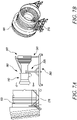
- Figure 7A is a side view of the first embodiment of the flat-packable gas turbine engine maintenance stand 200 of the present disclosure that is supporting the gas turbine engine as the fan case module that is supported on the fan case dolly 270 is removed from the gas turbine engine by wheeling the fan case dolly shown in Figure 6 in an axial direction away from the gas turbine engine maintenance stand.
- the maintenance stand continues to support the engine core module 140 of the gas turbine engine and the turbine module 150 of the gas turbine engine.
- Figure 7B is a perspective view of the fan case module that has been removed from the gas turbine engine, the fan case module being supported on the fan case dolly 270. In Figures 7A and 7B the intake module is still attached to the fan case 130.
- the low pressure compressor 105 module of the gas turbine engine 100 is separated from the engine core 128 using a mobile lifting gantry 280 and transported for storage in a suitable location until required for reassembly.
- Mobile lifting gantries are commercially available or can be constructed for the purpose using known methods.
- Figure 8A is a perspective view of the first embodiment of the flat-packable gas turbine engine maintenance stand of the present disclosure supporting the gas turbine engine with low pressure compressor 105 module having been removed from the gas turbine engine using the mobile lifting gantry 280.
- Figure 8B is a perspective view of a purpose-made transportation and storage pallet 285 for the low pressure compressor 105 module that has been removed from the gas turbine engine.
- strip tooling can be fitted to the intermediate pressure compressor disk and shaft assembly of the intermediate pressure compressor 106. Shaft connection points can be removed and the mobile lifting gantry can be pushed back under load.
- the removed intermediate pressure compressor module can be suitably stored, for example on a purpose made intermediate compressor module stand 290.
- Figure 9A is a perspective view of the first embodiment of the flat-packable gas turbine engine maintenance stand of the present disclosure supporting the gas turbine engine with an intermediate pressure compressor 106 module having been removed from the gas turbine engine using the mobile lifting gantry 280.
- Figure 9B is a side view of the intermediate pressure compressor 106 module suspended from the mobile lifting gantry 280 in preparation for being lowered on a purpose made intermediate compressor module stand 290.
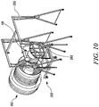
- Figure 10 is a perspective view of the first embodiment of the flat-packable gas turbine engine maintenance stand 200 of the present disclosure that is supporting a fully assembled gas turbine engine with a mobile lifting gantry crane 295 located adjacent and fitted to the low pressure turbine 116 module of the gas turbine engine in preparation for removing the low pressure turbine module from the gas turbine engine.
- Mobile lifting gantry cranes are commercially available or can be constructed for the purpose using known methods. Whether the engine is stripped from the front of the back is determined by the nature of the maintenance that is required. When stripping from the back as per Figure 10 , tooling 292 may be used to provide an interface for handling and protection purposes.
- the mobile lifting gantry crane 295 is moved into position over the gas turbine engine 100 and weight optimised tooling is fitted to the low pressure turbine 116 module.
- the low pressure tubine module and is removed using the traverse function of the mobile lifting gantry crane 295 and hydraulic pushing tools (not shown). Once removed the low pressure turbine module 116 may be initially loaded onto a parking stand 297 and may later be transferred to a purpose-made LPT transportation and storage trolley 300 (or a suitable stand) for the low pressure turbine module.
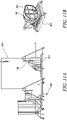
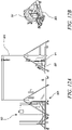
- Figure 11A is a side view of the first embodiment of the flat-packable gas turbine engine maintenance stand 200 of the present disclosure where the low pressure turbine 116 module of the gas turbine engine has been separated from the gas turbine engine using the mobile lifting gantry crane 295 shown in Figure 10 .
- Figure 11B is a perspective view of the low pressure turbine 116 module of the gas turbine engine located on the transportation and storage trolley 300 for the low pressure turbine module.
- the mobile lifting gantry crane 295 can be moved into position over the engine 100 and weight optimised tooling can be fitted to the intermediate pressure turbine 114.
- the intermediate pressure turbine may be removed using a traverse function of the mobile lifting gantry crane 295 and the hydraulic pushing tools (not shown). Once removed, the intermediate pressure turbine may be initially loaded onto a parking stand 297 and may later be transferred to a purpose-made IPT transportation and storage trolley 305 (or a suitable stand) for the intermediate pressure turbine module.
- Figure 12A is a side view of the first embodiment of the flat-packable gas turbine engine maintenance stand of the present disclosure where the intermediate pressure turbine 114 module of the gas turbine engine has been separated from the gas turbine engine using the gantry crane 295 shown in Figure 10 .
- Figure 12B is a perspective view of the intermediate pressure turbine 114 module of the gas turbine engine located on a purpose-made transportation and storage trolley or stand for the intermediate pressure turbine module.
- the high pressure module 308 comprising the high pressure turbine 112 and the high pressure compressor 108 and is removed using the traverse function of the mobile lifting gantry crane 295 and hydraulic pushing tools (not shown).
- the high pressure module may initially be loaded onto a purpose-made high pressure (HP) module transportation and storage trolley 310 for the high pressure turbine module and may later be transferred to a parking stand 297.
- HP high pressure
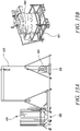
- Figure 13A is a side view of the first embodiment of the flat-packable gas turbine engine maintenance stand 200 of the present disclosure where the high pressure turbine module 112 of the gas turbine engine has been separated from the gas turbine engine using the mobile lifting gantry crane 295 first shown in Figure 10 .
- Figure 13B is a perspective view of the high pressure turbine module of the gas turbine engine located on the high pressure (HP) module transportation and storage trolley 310.
- an intercase module 320 is then left in the flat-packable gas turbine engine maintenance stand 200 of the present disclosure and suitable storage or lifting tooling is used to move the intercase module.
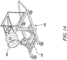
- the intercase module 320 can be stored on the stand 200 if not included in the work scope or taken off and stored. This is shown in Figure 14 , which is a perspective view of the first embodiment of the flat-packable gas turbine engine maintenance stand of the present disclosure only supporting an intercase module of the gas turbine engine.
- An intercase module support 325 may be provided on the stand 200, e.g. on the base beams 205, to assist in supporting the intercase module.
- While the flat-packable gas turbine engine maintenance stand 200 of the present disclosure may include wheel assemblies 260 to transport the stand a lifting frame 330 may be provided to assist in moving the stand, for example using a forklift.
- Figure 15 shows a perspective view of the first embodiment of the flat-packable gas turbine engine maintenance stand of the present disclosure with such a lifting frame provided.
- the flat-packable gas turbine engine maintenance stand 200 of the present disclosure may be adapted to be lifted by a crane.
- a lift adapter 340 may be used for such a purpose.
- Such a lift adapter may be detachably secured to the base beams 205 of the stand, e.g. adjacent the first ends 210 thereof. This may be used in combination with lifting interfaces suitably located on each of the engine core module support arms 230.
- Figure 16A show a perspective view of the first embodiment of the flat-packable gas turbine engine maintenance stand of the present disclosure and such a lift adapter that has yet to be installed onto the gas turbine engine maintenance stand.
- Figure 16B shows the same stand with a lift adapter installed.
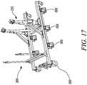
- stand supports 350 When wishing to transport the stand 200 on a plurality of stand supports 350 may usefully be provided upon which the stand 200 can be lifted.
- the stand supports 350 keep the wheel assembles 260 off the ground.
- Figure 17 is a perspective view of the first embodiment of the flat-packable gas turbine engine maintenance stand of the present disclosure raised on a plurality of stand supports.
- stand supports 350 may be fixed on a pallet for transportation purposes.
- the stand and its parts may be made of any material suitable for their purpose and function.
- the stand or at least some of its parts may be provided with a protective coating, for example a coating that provides corrosion resistance.
- the stand or at least some of its parts may be galvanised.
- the present disclosure may be said to more simply to provide a method of maintaining a gas turbine engine 100 of an aircraft, the gas turbine engine comprising modules including an engine core module 140 that houses a high pressure compressor 108 and a turbine module 150 that houses a high pressure turbine 112 and a low pressure turbine 116. That method comprises the steps of:
Landscapes
- Engineering & Computer Science (AREA)
- Mechanical Engineering (AREA)
- General Engineering & Computer Science (AREA)
- Chemical & Material Sciences (AREA)
- Combustion & Propulsion (AREA)
- Transportation (AREA)
- Manufacturing & Machinery (AREA)
- Aviation & Aerospace Engineering (AREA)
- Structures Of Non-Positive Displacement Pumps (AREA)
- Packaging Of Machine Parts And Wound Products (AREA)
Claims (12)
- Flach verpackbarer Gasturbinentriebwerks-Wartungsständer (200) für ein Gasturbinentriebwerk (100), das abnehmbare Module umfasst, die ein Triebwerkskernmodul (140), das einen Hochdruckkompressor (108) aufnimmt, und ein Turbinenmodul (150), das eine Niederdruckturbine (116) aufnimmt, enthalten, wobei der flach verpackbare Gasturbinentriebwerks-Wartungsständer umfasst:ein Paar Basisträger (205), wobei jeder Basisträger ein erstes Ende (210), einen Mittelabschnitt (215) und ein zweites Ende (220) aufweist;eine Triebwerkskernmodul-Stütze (225), die das Paar Basisträger (205) an ihrem Mittelabschnitt (215) überspannt, wobei die Triebwerkskernmodul-Stütze Triebwerkskernmodul-Stützarme (230) aufweist, die konfiguriert sind, um in gegenüberliegende Seiten des Triebwerkskernmoduls (140) des Gasturbinentriebwerks einzugreifen; undeine Turbinenmodul-Stütze (240), die das Paar Basisträger (205) benachbart zu ihren zweiten Enden (220) überspannt, wobei die Turbinenmodul-Stütze Turbinenmodul-Stützarme (245) aufweist, die konfiguriert sind, um in gegenüberliegende Seiten des Turbinenmoduls (150) des Gasturbinentriebwerks einzugreifen;wobei jeder Triebwerkskernmodul-Stützarm (230) gegen einen der Basisträger (205) durch ein oder mehrere strukturelle Stützelemente (237) abgestützt ist; unddie Triebwerkskernmodul-Stütze (225) einen Mittelabschnitt (225) aufweist, der jeden Triebwerkskernmodul-Stützarm (230) verbindet und jeder Triebwerkskernmodul-Stützarm gegen den Mittelabschnitt der Triebwerkskernmodul-Stütze (225) durch ein oder mehrere strukturelle Stützelemente (237) abgestützt ist.
- Flach verpackbarer Gasturbinentriebwerks-Wartungsständer (200) nach Anspruch 1, wobei jeder Triebwerkskernmodul-Stützarm (230) eine Triebwerkskernmodul-Greifanordnung (235) aufweist, die konfiguriert ist, um das Triebwerkskernmodul (140) des Gasturbinentriebwerks (100) fest in Eingriff zu nehmen.
- Flach verpackbarer Gasturbinentriebwerks-Wartungsständer (200) nach Anspruch 1 oder 2, wobei die Turbinenmodul-Stütze (240) mindestens ein Gelenk (252) zum Reduzieren von Torsion beim Verbinden der Turbinenmodul-Stütze mit dem Turbinenmodul enthält.
- Flach verpackbarer Gasturbinentriebwerks-Wartungsständer (200) nach einen der vorhergehenden Ansprüche, wobei jeder Turbinenmodul-Stützarm (245) eine Turbinenmodul-Greifanordnung (250) aufweist, die konfiguriert ist, um das Turbinenmodul (150) des Gasturbinentriebwerks (100) fest in Eingriff zu nehmen.
- Flach verpackbarer Gasturbinentriebwerks-Wartungsständer (200) nach einem der vorhergehenden Ansprüche, wobei die Turbinenmodul-Stütze (240) von dem Ständer (200) abnehmbar ist.
- Flach verpackbarer Gasturbinentriebwerks-Wartungsständer (200) nach einem der vorhergehenden Ansprüche, wobei jeder Basisträger eine Vielzahl von Radanordnungen (260) aufweist.
- Flach verpackbarer Gasturbinentriebwerks-Wartungsständer (200) nach einem der vorhergehenden Ansprüche, wobei das Triebwerkskemmodul (140), das mit der Triebwerkskernmodul-Stütze (225) in Eingriff gebracht werden soll, auch einen oder mehrere von einem Niederdruckkompressor (105) und einem Zwischendruckkompressor (106) aufnimmt oder abnehmbar enthält.
- Flach verpackbarer Gasturbinentriebwerks-Wartungsständer (200) nach einem der vorhergehenden Ansprüche, wobei das Turbinenmodul (150), das mit der Turbinenmodul-Stütze (240) in Eingriff gebracht werden soll, auch eine Zwischendruckturbine (114) aufnimmt oder abnehmbar enthält.
- Flach verpackbarer Gasturbinentriebwerks-Wartungsständer (200) nach einem der vorhergehenden Ansprüche, wobei das Triebwerkskemmodul (140), das mit der Triebwerkskernmodul-Stütze (225) in Eingriff gebracht werden soll, oder das Turbinenmodul (150), das mit der Turbinenmodul-Stütze (240) in Eingriff gebracht werden soll, auch eine Hochdruckturbine (112) aufnimmt oder abnehmbar enthält.
- Verfahren zum Warten eines Gasturbinentriebwerks (100) eines Flugzeugs, wobei das Gasturbinentriebwerk Module umfasst, die ein Triebwerkskernmodul (140), das einen Hochdruckkompressor (108) aufnimmt, und ein Turbinenmodul (150), das eine Niederdruckturbine (116) aufnimmt, enthalten, wobei das Verfahren die Schritte umfasst:Positionieren eines flach verpackbaren Gasturbinentriebwerks-Wartungsständers (200) nach einem der vorhergehenden Ansprüche unter dem zu wartenden Gasturbinentriebwerk;Bewegen des Gasturbinentriebwerks (100) von dem Flugzeug auf den flach verpackbaren Gasturbinentriebwerks-Wartungsständer (200);lösbares in Eingriff Bringen der Triebwerkskernmodul-Stützarme (230) des flach verpackbaren Gasturbinentriebwerks-Wartungsständers (200) mit dem Triebwerkskernmodul (140) des Gasturbinentriebwerks;lösbares Ineingriffbringen die Turbinenmodul-Stützarme (245) des flach verpackbaren Gasturbinentriebwerks-Wartungsständers (200) mit dem Turbinenmodul (150) des Gasturbinentriebwerks;Entfernen eines oder mehrerer Module des Gasturbinentriebwerks, während das Triebwerkskernmodul in dem verpackbaren Gasturbinentriebwerks-Wartungsständer (200) abgestützt wird;Wiederzusammenbau des Gasturbinentriebwerks (100), sobald die Wartung abgeschlossen ist;Abnehmen der Triebwerkskernmodul-Stützarme (230) und der Turbinenmodul-Stützarme (245) von dem Gasturbinentriebwerk; undRückführen des Gasturbinentriebwerks (100) zurück in das Flugzeug.
- Teilesatz, der ein Paar Basisträger (205), eine Triebwerkskernmodul-Stütze (225) und eine Turbinenmodul-Stütze (240) umfasst, wobei der Satz einen flach verpackbaren Gasturbinentriebwerks-Wartungsständer (200) nach einem der Ansprüche 1 bis 9 bildet.
- Teilesatz nach Anspruch 11, der flach in einem Lagerbehälter verpackt ist.
Applications Claiming Priority (1)
| Application Number | Priority Date | Filing Date | Title |
|---|---|---|---|
| GBGB1904433.8A GB201904433D0 (en) | 2019-03-29 | 2019-03-29 | Gas turbine engine maintenance stand |
Publications (2)
| Publication Number | Publication Date |
|---|---|
| EP3715592A1 EP3715592A1 (de) | 2020-09-30 |
| EP3715592B1 true EP3715592B1 (de) | 2022-05-04 |
Family
ID=66442880
Family Applications (1)
| Application Number | Title | Priority Date | Filing Date |
|---|---|---|---|
| EP20162598.5A Active EP3715592B1 (de) | 2019-03-29 | 2020-03-12 | Gasturbinenmotorwartungsstand und zugehöriges verfahren zum warten eines gasturbinenmotors |
Country Status (3)
| Country | Link |
|---|---|
| US (1) | US11506087B2 (de) |
| EP (1) | EP3715592B1 (de) |
| GB (1) | GB201904433D0 (de) |
Cited By (1)
| Publication number | Priority date | Publication date | Assignee | Title |
|---|---|---|---|---|
| EP4603676A1 (de) | 2024-02-14 | 2025-08-20 | Rolls-Royce plc | Motorständer |
Families Citing this family (7)
| Publication number | Priority date | Publication date | Assignee | Title |
|---|---|---|---|---|
| US12005538B2 (en) * | 2020-07-28 | 2024-06-11 | The Boeing Company | Methods and systems for supporting and positioning mechanical components or tools |
| US20220348400A1 (en) * | 2021-04-29 | 2022-11-03 | Viettel Group | Gas turbine engine storage and transport container |
| US12246845B2 (en) | 2021-05-20 | 2025-03-11 | General Electric Company | Methods and apparatus for mounting a gas turbine engine |
| CN113245813B (zh) * | 2021-07-16 | 2021-10-01 | 成都飞机工业(集团)有限责任公司 | 一种用于飞机快速装配的自定位装配系统及方法 |
| CN215968596U (zh) * | 2021-10-28 | 2022-03-08 | 天津大学滨海工业研究院有限公司 | 一种航空发动机维修平台 |
| MA62202A1 (fr) * | 2023-09-05 | 2025-03-28 | Université Internationale de RABAT | Support d'un moteur d’avion à turbine à gaz utilisé pour la maintenance |
| US20250367814A1 (en) * | 2024-05-30 | 2025-12-04 | Pratt & Whitney Canada Corp. | Support stand assembly for aircraft engine |
Family Cites Families (16)
| Publication number | Priority date | Publication date | Assignee | Title |
|---|---|---|---|---|
| FR2370616A1 (fr) | 1976-11-11 | 1978-06-09 | Lockheed Corp | Chassis transportable pour moteur |
| NZ241415A (en) | 1992-01-27 | 1995-04-27 | Air New Zealand Ltd | Gas turbine engine transporting frames |
| DE10216258B4 (de) | 2001-10-04 | 2004-09-30 | Fürsicht Maschinen GmbH | Triebwerkstand |
| GB0613929D0 (en) | 2006-07-13 | 2006-08-23 | Rolls Royce Plc | An engine core stand arrangement and method of removal and transportation of an engine core |
| GB2462405B (en) | 2008-05-29 | 2010-09-08 | Rolls Royce Plc | A cradle arrangement |
| FR2990190B1 (fr) * | 2012-05-02 | 2015-06-19 | Snecma | Outil de manutention d'un module de moteur d'aeronef |
| US8851441B2 (en) * | 2012-05-17 | 2014-10-07 | Solar Turbine Inc. | Engine skid assembly |
| GB2509229A (en) * | 2013-11-19 | 2014-06-25 | Rolls Royce Plc | Gas turbine engine fan stand with hinged rotating frame |
| GB2509230A (en) * | 2013-11-19 | 2014-06-25 | Rolls Royce Plc | Gas turbine engine stand with slide rail and lock mechanism |
| WO2015168637A1 (en) * | 2014-05-02 | 2015-11-05 | Morey Joel T | Aircraft engine stand |
| US9783313B2 (en) * | 2015-06-23 | 2017-10-10 | Rohr, Inc. | Installing or removing aircraft engines |
| DE102015214667B4 (de) | 2015-07-31 | 2020-11-19 | MTU Aero Engines AG | Montagesystem zum Montieren, Demontieren und/oder Warten einer Gasturbine |
| US10221724B2 (en) | 2015-10-15 | 2019-03-05 | United Technologies Corporation | Horizontal engine build stand |
| FR3043000B1 (fr) | 2015-10-29 | 2018-04-13 | Safran Aircraft Engines | Portique d'assemblage de moteur |
| FR3058406B1 (fr) * | 2016-11-10 | 2020-11-06 | Next Aero Concept | Dispositif de pose/depose et de transfert de moteur d'aeronef. |
| FR3058987B1 (fr) * | 2016-11-24 | 2019-08-02 | Safran Aircraft Engines | Organe et chariot pour la depose, le transport, et la maintenance, d'une turbomachine |
-
2019
- 2019-03-29 GB GBGB1904433.8A patent/GB201904433D0/en not_active Ceased
-
2020
- 2020-03-12 EP EP20162598.5A patent/EP3715592B1/de active Active
- 2020-03-20 US US16/824,805 patent/US11506087B2/en active Active
Cited By (1)
| Publication number | Priority date | Publication date | Assignee | Title |
|---|---|---|---|---|
| EP4603676A1 (de) | 2024-02-14 | 2025-08-20 | Rolls-Royce plc | Motorständer |
Also Published As
| Publication number | Publication date |
|---|---|
| US20200308988A1 (en) | 2020-10-01 |
| GB201904433D0 (en) | 2019-05-15 |
| EP3715592A1 (de) | 2020-09-30 |
| US11506087B2 (en) | 2022-11-22 |
Similar Documents
| Publication | Publication Date | Title |
|---|---|---|
| EP3715592B1 (de) | Gasturbinenmotorwartungsstand und zugehöriges verfahren zum warten eines gasturbinenmotors | |
| US11306620B2 (en) | Method of reassembling a gas turbine engine | |
| EP2873621B1 (de) | Gasturbinenmotorständer | |
| US11952146B2 (en) | Systems and methods for loading and unloading a cargo aircraft | |
| EP1878662B1 (de) | Motorkernständeranordnung und Verfahren zum Abnehmen und Transportieren eines Motorkerns | |
| US20230202658A1 (en) | Systems and methods for loading and unloading a cargo aircraft utilizing a curved path | |
| US12312099B2 (en) | Removable cargo floor systems and methods for cargo aircraft | |
| WO2021046555A1 (en) | Systems, methods, and vehicles for transporting large cargo onto and off a transport vehicle | |
| US20130145770A1 (en) | Substitution device for aircraft engine | |
| US20240239488A1 (en) | Systems and methods for assembling large cargo and loading it onto a cargo aircraft | |
| US20240124156A1 (en) | Devices and methods for cantilevered-support of aircraft cargo payloads in forward and aft ends of a cargo bay | |
| US20250257670A1 (en) | Engine stand | |
| WO2022203880A2 (en) | Devices and methods for cantilevered-support of aircraft cargo payloads in forward and aft ends of a cargo bay | |
| CN222432601U (zh) | 一种大型飞机机身用支撑装置 | |
| CN118479054A (zh) | 大型飞机机身陆运装载工装 | |
| CA2206983C (en) | Burner replacing system | |
| HK1117214B (en) | An engine core stand arrangement and method of removal and transportation of an engine core |
Legal Events
| Date | Code | Title | Description |
|---|---|---|---|
| PUAI | Public reference made under article 153(3) epc to a published international application that has entered the european phase |
Free format text: ORIGINAL CODE: 0009012 |
|
| STAA | Information on the status of an ep patent application or granted ep patent |
Free format text: STATUS: THE APPLICATION HAS BEEN PUBLISHED |
|
| AK | Designated contracting states |
Kind code of ref document: A1 Designated state(s): AL AT BE BG CH CY CZ DE DK EE ES FI FR GB GR HR HU IE IS IT LI LT LU LV MC MK MT NL NO PL PT RO RS SE SI SK SM TR |
|
| AX | Request for extension of the european patent |
Extension state: BA ME |
|
| STAA | Information on the status of an ep patent application or granted ep patent |
Free format text: STATUS: REQUEST FOR EXAMINATION WAS MADE |
|
| 17P | Request for examination filed |
Effective date: 20210329 |
|
| RBV | Designated contracting states (corrected) |
Designated state(s): AL AT BE BG CH CY CZ DE DK EE ES FI FR GB GR HR HU IE IS IT LI LT LU LV MC MK MT NL NO PL PT RO RS SE SI SK SM TR |
|
| GRAP | Despatch of communication of intention to grant a patent |
Free format text: ORIGINAL CODE: EPIDOSNIGR1 |
|
| STAA | Information on the status of an ep patent application or granted ep patent |
Free format text: STATUS: GRANT OF PATENT IS INTENDED |
|
| GRAS | Grant fee paid |
Free format text: ORIGINAL CODE: EPIDOSNIGR3 |
|
| INTG | Intention to grant announced |
Effective date: 20220119 |
|
| GRAA | (expected) grant |
Free format text: ORIGINAL CODE: 0009210 |
|
| STAA | Information on the status of an ep patent application or granted ep patent |
Free format text: STATUS: THE PATENT HAS BEEN GRANTED |
|
| AK | Designated contracting states |
Kind code of ref document: B1 Designated state(s): AL AT BE BG CH CY CZ DE DK EE ES FI FR GB GR HR HU IE IS IT LI LT LU LV MC MK MT NL NO PL PT RO RS SE SI SK SM TR |
|
| REG | Reference to a national code |
Ref country code: GB Ref legal event code: FG4D |
|
| REG | Reference to a national code |
Ref country code: CH Ref legal event code: EP |
|
| REG | Reference to a national code |
Ref country code: AT Ref legal event code: REF Ref document number: 1489242 Country of ref document: AT Kind code of ref document: T Effective date: 20220515 |
|
| REG | Reference to a national code |
Ref country code: IE Ref legal event code: FG4D Ref country code: DE Ref legal event code: R096 Ref document number: 602020002913 Country of ref document: DE |
|
| REG | Reference to a national code |
Ref country code: LT Ref legal event code: MG9D |
|
| REG | Reference to a national code |
Ref country code: NL Ref legal event code: MP Effective date: 20220504 |
|
| REG | Reference to a national code |
Ref country code: AT Ref legal event code: MK05 Ref document number: 1489242 Country of ref document: AT Kind code of ref document: T Effective date: 20220504 |
|
| PG25 | Lapsed in a contracting state [announced via postgrant information from national office to epo] |
Ref country code: SE Free format text: LAPSE BECAUSE OF FAILURE TO SUBMIT A TRANSLATION OF THE DESCRIPTION OR TO PAY THE FEE WITHIN THE PRESCRIBED TIME-LIMIT Effective date: 20220504 Ref country code: PT Free format text: LAPSE BECAUSE OF FAILURE TO SUBMIT A TRANSLATION OF THE DESCRIPTION OR TO PAY THE FEE WITHIN THE PRESCRIBED TIME-LIMIT Effective date: 20220905 Ref country code: NO Free format text: LAPSE BECAUSE OF FAILURE TO SUBMIT A TRANSLATION OF THE DESCRIPTION OR TO PAY THE FEE WITHIN THE PRESCRIBED TIME-LIMIT Effective date: 20220804 Ref country code: NL Free format text: LAPSE BECAUSE OF FAILURE TO SUBMIT A TRANSLATION OF THE DESCRIPTION OR TO PAY THE FEE WITHIN THE PRESCRIBED TIME-LIMIT Effective date: 20220504 Ref country code: LT Free format text: LAPSE BECAUSE OF FAILURE TO SUBMIT A TRANSLATION OF THE DESCRIPTION OR TO PAY THE FEE WITHIN THE PRESCRIBED TIME-LIMIT Effective date: 20220504 Ref country code: HR Free format text: LAPSE BECAUSE OF FAILURE TO SUBMIT A TRANSLATION OF THE DESCRIPTION OR TO PAY THE FEE WITHIN THE PRESCRIBED TIME-LIMIT Effective date: 20220504 Ref country code: GR Free format text: LAPSE BECAUSE OF FAILURE TO SUBMIT A TRANSLATION OF THE DESCRIPTION OR TO PAY THE FEE WITHIN THE PRESCRIBED TIME-LIMIT Effective date: 20220805 Ref country code: FI Free format text: LAPSE BECAUSE OF FAILURE TO SUBMIT A TRANSLATION OF THE DESCRIPTION OR TO PAY THE FEE WITHIN THE PRESCRIBED TIME-LIMIT Effective date: 20220504 Ref country code: ES Free format text: LAPSE BECAUSE OF FAILURE TO SUBMIT A TRANSLATION OF THE DESCRIPTION OR TO PAY THE FEE WITHIN THE PRESCRIBED TIME-LIMIT Effective date: 20220504 Ref country code: BG Free format text: LAPSE BECAUSE OF FAILURE TO SUBMIT A TRANSLATION OF THE DESCRIPTION OR TO PAY THE FEE WITHIN THE PRESCRIBED TIME-LIMIT Effective date: 20220804 Ref country code: AT Free format text: LAPSE BECAUSE OF FAILURE TO SUBMIT A TRANSLATION OF THE DESCRIPTION OR TO PAY THE FEE WITHIN THE PRESCRIBED TIME-LIMIT Effective date: 20220504 |
|
| PG25 | Lapsed in a contracting state [announced via postgrant information from national office to epo] |
Ref country code: RS Free format text: LAPSE BECAUSE OF FAILURE TO SUBMIT A TRANSLATION OF THE DESCRIPTION OR TO PAY THE FEE WITHIN THE PRESCRIBED TIME-LIMIT Effective date: 20220504 Ref country code: PL Free format text: LAPSE BECAUSE OF FAILURE TO SUBMIT A TRANSLATION OF THE DESCRIPTION OR TO PAY THE FEE WITHIN THE PRESCRIBED TIME-LIMIT Effective date: 20220504 Ref country code: LV Free format text: LAPSE BECAUSE OF FAILURE TO SUBMIT A TRANSLATION OF THE DESCRIPTION OR TO PAY THE FEE WITHIN THE PRESCRIBED TIME-LIMIT Effective date: 20220504 Ref country code: IS Free format text: LAPSE BECAUSE OF FAILURE TO SUBMIT A TRANSLATION OF THE DESCRIPTION OR TO PAY THE FEE WITHIN THE PRESCRIBED TIME-LIMIT Effective date: 20220904 |
|
| PG25 | Lapsed in a contracting state [announced via postgrant information from national office to epo] |
Ref country code: SM Free format text: LAPSE BECAUSE OF FAILURE TO SUBMIT A TRANSLATION OF THE DESCRIPTION OR TO PAY THE FEE WITHIN THE PRESCRIBED TIME-LIMIT Effective date: 20220504 Ref country code: SK Free format text: LAPSE BECAUSE OF FAILURE TO SUBMIT A TRANSLATION OF THE DESCRIPTION OR TO PAY THE FEE WITHIN THE PRESCRIBED TIME-LIMIT Effective date: 20220504 Ref country code: RO Free format text: LAPSE BECAUSE OF FAILURE TO SUBMIT A TRANSLATION OF THE DESCRIPTION OR TO PAY THE FEE WITHIN THE PRESCRIBED TIME-LIMIT Effective date: 20220504 Ref country code: EE Free format text: LAPSE BECAUSE OF FAILURE TO SUBMIT A TRANSLATION OF THE DESCRIPTION OR TO PAY THE FEE WITHIN THE PRESCRIBED TIME-LIMIT Effective date: 20220504 Ref country code: DK Free format text: LAPSE BECAUSE OF FAILURE TO SUBMIT A TRANSLATION OF THE DESCRIPTION OR TO PAY THE FEE WITHIN THE PRESCRIBED TIME-LIMIT Effective date: 20220504 Ref country code: CZ Free format text: LAPSE BECAUSE OF FAILURE TO SUBMIT A TRANSLATION OF THE DESCRIPTION OR TO PAY THE FEE WITHIN THE PRESCRIBED TIME-LIMIT Effective date: 20220504 |
|
| REG | Reference to a national code |
Ref country code: DE Ref legal event code: R097 Ref document number: 602020002913 Country of ref document: DE |
|
| PLBE | No opposition filed within time limit |
Free format text: ORIGINAL CODE: 0009261 |
|
| STAA | Information on the status of an ep patent application or granted ep patent |
Free format text: STATUS: NO OPPOSITION FILED WITHIN TIME LIMIT |
|
| PG25 | Lapsed in a contracting state [announced via postgrant information from national office to epo] |
Ref country code: AL Free format text: LAPSE BECAUSE OF FAILURE TO SUBMIT A TRANSLATION OF THE DESCRIPTION OR TO PAY THE FEE WITHIN THE PRESCRIBED TIME-LIMIT Effective date: 20220504 |
|
| 26N | No opposition filed |
Effective date: 20230207 |
|
| PG25 | Lapsed in a contracting state [announced via postgrant information from national office to epo] |
Ref country code: SI Free format text: LAPSE BECAUSE OF FAILURE TO SUBMIT A TRANSLATION OF THE DESCRIPTION OR TO PAY THE FEE WITHIN THE PRESCRIBED TIME-LIMIT Effective date: 20220504 |
|
| P01 | Opt-out of the competence of the unified patent court (upc) registered |
Effective date: 20230528 |
|
| PG25 | Lapsed in a contracting state [announced via postgrant information from national office to epo] |
Ref country code: MC Free format text: LAPSE BECAUSE OF FAILURE TO SUBMIT A TRANSLATION OF THE DESCRIPTION OR TO PAY THE FEE WITHIN THE PRESCRIBED TIME-LIMIT Effective date: 20220504 |
|
| REG | Reference to a national code |
Ref country code: CH Ref legal event code: PL |
|
| REG | Reference to a national code |
Ref country code: BE Ref legal event code: MM Effective date: 20230331 |
|
| PG25 | Lapsed in a contracting state [announced via postgrant information from national office to epo] |
Ref country code: LU Free format text: LAPSE BECAUSE OF NON-PAYMENT OF DUE FEES Effective date: 20230312 |
|
| REG | Reference to a national code |
Ref country code: IE Ref legal event code: MM4A |
|
| PG25 | Lapsed in a contracting state [announced via postgrant information from national office to epo] |
Ref country code: LI Free format text: LAPSE BECAUSE OF NON-PAYMENT OF DUE FEES Effective date: 20230331 Ref country code: IT Free format text: LAPSE BECAUSE OF FAILURE TO SUBMIT A TRANSLATION OF THE DESCRIPTION OR TO PAY THE FEE WITHIN THE PRESCRIBED TIME-LIMIT Effective date: 20220504 Ref country code: IE Free format text: LAPSE BECAUSE OF NON-PAYMENT OF DUE FEES Effective date: 20230312 Ref country code: CH Free format text: LAPSE BECAUSE OF NON-PAYMENT OF DUE FEES Effective date: 20230331 |
|
| PG25 | Lapsed in a contracting state [announced via postgrant information from national office to epo] |
Ref country code: BE Free format text: LAPSE BECAUSE OF NON-PAYMENT OF DUE FEES Effective date: 20230331 |
|
| PG25 | Lapsed in a contracting state [announced via postgrant information from national office to epo] |
Ref country code: BG Free format text: LAPSE BECAUSE OF FAILURE TO SUBMIT A TRANSLATION OF THE DESCRIPTION OR TO PAY THE FEE WITHIN THE PRESCRIBED TIME-LIMIT Effective date: 20220504 |
|
| PG25 | Lapsed in a contracting state [announced via postgrant information from national office to epo] |
Ref country code: BG Free format text: LAPSE BECAUSE OF FAILURE TO SUBMIT A TRANSLATION OF THE DESCRIPTION OR TO PAY THE FEE WITHIN THE PRESCRIBED TIME-LIMIT Effective date: 20220504 |
|
| PG25 | Lapsed in a contracting state [announced via postgrant information from national office to epo] |
Ref country code: CY Free format text: LAPSE BECAUSE OF FAILURE TO SUBMIT A TRANSLATION OF THE DESCRIPTION OR TO PAY THE FEE WITHIN THE PRESCRIBED TIME-LIMIT; INVALID AB INITIO Effective date: 20200312 |
|
| PG25 | Lapsed in a contracting state [announced via postgrant information from national office to epo] |
Ref country code: HU Free format text: LAPSE BECAUSE OF FAILURE TO SUBMIT A TRANSLATION OF THE DESCRIPTION OR TO PAY THE FEE WITHIN THE PRESCRIBED TIME-LIMIT; INVALID AB INITIO Effective date: 20200312 |
|
| PG25 | Lapsed in a contracting state [announced via postgrant information from national office to epo] |
Ref country code: TR Free format text: LAPSE BECAUSE OF FAILURE TO SUBMIT A TRANSLATION OF THE DESCRIPTION OR TO PAY THE FEE WITHIN THE PRESCRIBED TIME-LIMIT Effective date: 20220504 |
|
| PGFP | Annual fee paid to national office [announced via postgrant information from national office to epo] |
Ref country code: GB Payment date: 20260323 Year of fee payment: 7 |
|
| PGFP | Annual fee paid to national office [announced via postgrant information from national office to epo] |
Ref country code: DE Payment date: 20260320 Year of fee payment: 7 |
|
| PGFP | Annual fee paid to national office [announced via postgrant information from national office to epo] |
Ref country code: FR Payment date: 20260323 Year of fee payment: 7 |