EP3715504A1 - Method for producing conversion-treated alloy material and device for regenerating conversion treatment solution used in method for producing conversion-treated alloy material - Google Patents
Method for producing conversion-treated alloy material and device for regenerating conversion treatment solution used in method for producing conversion-treated alloy material Download PDFInfo
- Publication number
- EP3715504A1 EP3715504A1 EP18880271.4A EP18880271A EP3715504A1 EP 3715504 A1 EP3715504 A1 EP 3715504A1 EP 18880271 A EP18880271 A EP 18880271A EP 3715504 A1 EP3715504 A1 EP 3715504A1
- Authority
- EP
- European Patent Office
- Prior art keywords
- treatment
- treatment solution
- oxalate
- bath
- regeneration
- Prior art date
- Legal status (The legal status is an assumption and is not a legal conclusion. Google has not performed a legal analysis and makes no representation as to the accuracy of the status listed.)
- Granted
Links
Images





Classifications
-
- C—CHEMISTRY; METALLURGY
- C23—COATING METALLIC MATERIAL; COATING MATERIAL WITH METALLIC MATERIAL; CHEMICAL SURFACE TREATMENT; DIFFUSION TREATMENT OF METALLIC MATERIAL; COATING BY VACUUM EVAPORATION, BY SPUTTERING, BY ION IMPLANTATION OR BY CHEMICAL VAPOUR DEPOSITION, IN GENERAL; INHIBITING CORROSION OF METALLIC MATERIAL OR INCRUSTATION IN GENERAL
- C23C—COATING METALLIC MATERIAL; COATING MATERIAL WITH METALLIC MATERIAL; SURFACE TREATMENT OF METALLIC MATERIAL BY DIFFUSION INTO THE SURFACE, BY CHEMICAL CONVERSION OR SUBSTITUTION; COATING BY VACUUM EVAPORATION, BY SPUTTERING, BY ION IMPLANTATION OR BY CHEMICAL VAPOUR DEPOSITION, IN GENERAL
- C23C22/00—Chemical surface treatment of metallic material by reaction of the surface with a reactive liquid, leaving reaction products of surface material in the coating, e.g. conversion coatings, passivation of metals
- C23C22/05—Chemical surface treatment of metallic material by reaction of the surface with a reactive liquid, leaving reaction products of surface material in the coating, e.g. conversion coatings, passivation of metals using aqueous solutions
- C23C22/06—Chemical surface treatment of metallic material by reaction of the surface with a reactive liquid, leaving reaction products of surface material in the coating, e.g. conversion coatings, passivation of metals using aqueous solutions using aqueous acidic solutions with pH less than 6
- C23C22/46—Chemical surface treatment of metallic material by reaction of the surface with a reactive liquid, leaving reaction products of surface material in the coating, e.g. conversion coatings, passivation of metals using aqueous solutions using aqueous acidic solutions with pH less than 6 containing oxalates
-
- C—CHEMISTRY; METALLURGY
- C23—COATING METALLIC MATERIAL; COATING MATERIAL WITH METALLIC MATERIAL; CHEMICAL SURFACE TREATMENT; DIFFUSION TREATMENT OF METALLIC MATERIAL; COATING BY VACUUM EVAPORATION, BY SPUTTERING, BY ION IMPLANTATION OR BY CHEMICAL VAPOUR DEPOSITION, IN GENERAL; INHIBITING CORROSION OF METALLIC MATERIAL OR INCRUSTATION IN GENERAL
- C23C—COATING METALLIC MATERIAL; COATING MATERIAL WITH METALLIC MATERIAL; SURFACE TREATMENT OF METALLIC MATERIAL BY DIFFUSION INTO THE SURFACE, BY CHEMICAL CONVERSION OR SUBSTITUTION; COATING BY VACUUM EVAPORATION, BY SPUTTERING, BY ION IMPLANTATION OR BY CHEMICAL VAPOUR DEPOSITION, IN GENERAL
- C23C22/00—Chemical surface treatment of metallic material by reaction of the surface with a reactive liquid, leaving reaction products of surface material in the coating, e.g. conversion coatings, passivation of metals
- C23C22/05—Chemical surface treatment of metallic material by reaction of the surface with a reactive liquid, leaving reaction products of surface material in the coating, e.g. conversion coatings, passivation of metals using aqueous solutions
- C23C22/06—Chemical surface treatment of metallic material by reaction of the surface with a reactive liquid, leaving reaction products of surface material in the coating, e.g. conversion coatings, passivation of metals using aqueous solutions using aqueous acidic solutions with pH less than 6
- C23C22/34—Chemical surface treatment of metallic material by reaction of the surface with a reactive liquid, leaving reaction products of surface material in the coating, e.g. conversion coatings, passivation of metals using aqueous solutions using aqueous acidic solutions with pH less than 6 containing fluorides or complex fluorides
-
- C—CHEMISTRY; METALLURGY
- C23—COATING METALLIC MATERIAL; COATING MATERIAL WITH METALLIC MATERIAL; CHEMICAL SURFACE TREATMENT; DIFFUSION TREATMENT OF METALLIC MATERIAL; COATING BY VACUUM EVAPORATION, BY SPUTTERING, BY ION IMPLANTATION OR BY CHEMICAL VAPOUR DEPOSITION, IN GENERAL; INHIBITING CORROSION OF METALLIC MATERIAL OR INCRUSTATION IN GENERAL
- C23C—COATING METALLIC MATERIAL; COATING MATERIAL WITH METALLIC MATERIAL; SURFACE TREATMENT OF METALLIC MATERIAL BY DIFFUSION INTO THE SURFACE, BY CHEMICAL CONVERSION OR SUBSTITUTION; COATING BY VACUUM EVAPORATION, BY SPUTTERING, BY ION IMPLANTATION OR BY CHEMICAL VAPOUR DEPOSITION, IN GENERAL
- C23C22/00—Chemical surface treatment of metallic material by reaction of the surface with a reactive liquid, leaving reaction products of surface material in the coating, e.g. conversion coatings, passivation of metals
- C23C22/86—Regeneration of coating baths
Definitions
- the present disclosure relates to a method for producing a chemically treated alloy material, and a chemical treatment solution regeneration apparatus that is used in the method for producing a chemically treated alloy material.
- the surface of an alloy material is subjected to chemical treatment for the purpose of imparting performance such as corrosion resistance, galling resistance, lubricity and paint adhesiveness to the alloy material.
- the chemical treatments include a phosphate treatment, an oxalate treatment and a chromate treatment.
- an oxalate treatment is performed for the purpose of increasing the lubricity, galling resistance and the like of the alloy material surface.
- An oxalate coating that is formed on an alloy material surface by an oxalate treatment increases the adhesiveness to the alloy material surface of a lubricating film that is to be formed thereon. In this way, the oxalate coating increases the lubricity and galling resistance of the alloy material surface.
- Patent Literature 1 discloses a technique that provides a high chromium steel piston that has excellent galling resistance by forming an oxalate coating on the surface of a piston for use in an internal combustion engine.
- An oxalate treatment is usually performed by immersing an alloy material in an oxalate treatment solution containing oxalate ions, and causing a reacting between the alloy material surface and the oxalate treatment solution.
- the oxalate treatment solution is used continuously.
- the chemical treatability decreases as the number of alloy materials that are successively treated increases. If the chemical treatability decrease, in some cases defects occur in the formation of the oxalate coating.
- Patent Literature 2 Japanese Patent Application Publication No. 2003-171777
- Patent Literature 3 Japanese Patent Application Publication No. 2-149677
- Patent Literature 2014-43606 Japanese Patent Application Publication No. 2014-43606
- Patent Literature 4 propose oxalate treatment solutions that can suppress a decrease in chemical treatability.
- Patent Literature 5 Japanese Patent Application Publication No. 62-199778
- Patent Literature 6 Japanese Patent Application Publication No. 6-220651
- a treatment solution for forming an oxalate coating disclosed in Patent Literature 2 is characterized by containing a polyoxyethylene-polyoxypropylene block copolymer in an amount of 0.03 to 1.0 wt% that is obtained by adding ethylene oxide of 20 to 50 wt% with respect to the total molecular weight to propylene glycol. It is described in Patent Literature 2 that by this means, in a method that performs cold drawing of stainless pipes, a reduction in the defect rate of products as well as suppression of a decrease in the life time of the oxalate coating treatment solution are achieved.
- a chemical treatment solution for cold working of stainless steel disclosed in Patent Literature 3 contains oxalic acid, and is characterized in that phosphoric acid is contained in an amount such that a phosphate ion concentration in the treatment solution falls within a range of 0.03 to 0.6 g/L. It is described in Patent Literature 3 that by this means, even though the balance of the composition of the chemical treatment solution becomes unbalanced to a certain extent, a chemical treatment solution is obtained that can form, on the surface of stainless steel, a chemical coating which can maintain favorable galling resistance.
- Patent Literature 4 An oxalate chemical treatment method disclosed in Patent Literature 4 is characterized by adding sulfite as an accelerating agent to an oxalate chemical treatment solution to perform a chemical treatment. It is described in Patent Literature 4 that by this means an oxalate coating can be formed on a material which has high corrosion resistance, such as a high corrosion-resistant stainless pipe.
- a method for forming an oxalate coating on Cr-Ni stainless steel disclosed in Patent Literature 5 is characterized by performing a sulfuric acid treatment immediately before an oxalate coating forming treatment. It is described in Patent Literature 5 that by this means the reactivity between the starting material and the oxalate treatment solution increases, and oxalate coating forming treatment can be performed efficiently even with respect to high Ni steel for which it had conventionally not been possible to perform an oxalate coating forming treatment on.
- a method for performing lubrication treatment of a highly corrosion resistant metal material disclosed in Patent Literature 6 is characterized by forming an oxalate coating without performing a pickling treatment after performing a shot blasting treatment with iron and steel shot on the surface of a metal material, and subsequently performing a lubrication treatment. It is described in Patent Literature 6 that by this means, even in the case of a metal material with high corrosion resistance on which it is difficult to perform a chemical treatment, a chemical coating can be sufficiently formed, and an appropriate lubrication treatment can be performed.
- An objective of the present disclosure is to provide a method for producing a chemically treated alloy material which suppresses a decrease in chemical treatability even in a case where chemical treatment is repeatedly performed, and a chemical treatment solution regeneration apparatus that can suppress a decrease in the chemical treatability of an alloy material even in a case of producing a chemically treated alloy material using an oxalate treatment solution with which chemical treatment is repeatedly performed.
- the method for producing a chemically treated alloy material of the present disclosure includes a chemical treatment step and a treatment solution regeneration step.
- a chemical treatment step an alloy material is immersed in an oxalate treatment solution containing oxalate ions and fluorine ions to perform a chemical treatment.
- the treatment solution regeneration step light is radiated to the oxalate treatment solution during the chemical treatment and/or the oxalate treatment solution after the chemical treatment.
- the chemical treatment solution regeneration apparatus of the present disclosure includes a treatment solution regeneration bath and a light radiation apparatus.
- the treatment solution regeneration bath is capable of containing an oxalate treatment solution during chemical treatment of an alloy material or after the chemical treatment of an alloy material.
- the oxalate treatment solution contains oxalate ions and fluorine ions.
- the light radiation apparatus includes one or more light source members. At least one part of the light source member is disposed inside the treatment solution regeneration bath or in the vicinity of an outer side of the treatment solution regeneration bath.
- the light radiation apparatus is capable of radiating light at the oxalate treatment solution during the chemical treatment or after the chemical treatment.
- the chemical treatment solution regeneration apparatus of the present disclosure can suppress a decrease in the chemical treatability of an alloy material even in the case of producing a chemically treated alloy material using an oxalate treatment solution with which chemical treatment is repeatedly performed.
- An oxalate coating is a coating that is consisting of iron (II) oxalate (chemical formula: Fe(COO) 2 ) and impurities.
- An oxalate coating is formed as the result of iron ions that are eluted from an alloy material and oxalate ions contained in an oxalate treatment solution reacting at the alloy material surface.
- the formation process of iron (II) oxalate in a chemical treatment is, specifically, shown by the following reaction formulae. Fe ⁇ Fe 2+ +2e - ... (1) (COOH) 2 ⁇ (COO) 2 2- +2H + ... (2) 2H + +2e - ⁇ H 2 ⁇ ... (3) (COO) 2 2- +Fe 2+ ⁇ Fe(COO) 2 ... (4)
- Fluorine ions are added into the oxalate treatment solution to accelerate the above reactions. Fluorine ions have an etching action. If fluorine ions are contained in an oxalate treatment solution for chemical treatment, the fluorine ions destroy an oxide film (passivation film) that is formed on the surface of the base metal surface in the process of producing an alloy material. As a result, formation of an oxalate coating is promoted. In addition, an oxalate coating can also be formed on a stainless alloy material having a passivation film with high corrosion resistance.
- an oxalate treatment solution containing oxalate ions and fluorine ions deteriorates due to repetitive use of the oxalate treatment solution. If the oxalate treatment solution deteriorates, the chemical treatability may decrease. If the chemical treatability decrease, in some cases defects may occur in the formation of an oxalate coating. Further, it is known that, in a case where the alloy material contains a large amount of Cr, that is, the alloy material is a so-called "difficult-to-chemically-treat material", even when the usage count of the oxalate treatment solution is low, the chemical treatability are low.
- the present inventors conducted a detailed study regarding the cause of a deterioration in an oxalate treatment solution and the cause of a decrease in chemical treatability. As a result, the present inventors obtained the findings described hereunder that had not been known before now.
- iron from the base metal dissolves and iron ions are generated. At such time, a part of the iron of the base metal dissolves as divalent iron ions (Fe 2+ ), as shown in the above Formula (1).
- the divalent iron ions react with oxalate ions to form iron (II) oxalate.
- Iron (II) oxalate is an insoluble salt. Therefore, when iron dissolves as divalent ions from the alloy material surface and reacts with oxalate ions, iron (II) oxalate rapidly deposits on the alloy material surface. The deposited iron (II) oxalate forms an oxalate coating.
- a part of the iron that eluted from the base metal is present in the oxalate treatment solution as trivalent iron ions (Fe 3+ ).
- the trivalent iron ions do not contribute to formation of the oxalate coating. That is, it is not the case that all of the iron ions that eluted from the base metal are consumed by the formation of an oxalate coating.
- a part of the iron ions do not participate in formation of the oxalate coating, and are present in the oxalate treatment solution.
- an alloy material which contains a large amount of Cr that is, a so-called "difficult-to-chemically-treat material”
- a passivation film that has markedly high corrosion resistance on the surface thereof. Therefore, in the case of performing an oxalate treatment on a difficult-to-chemically-treat material, it is necessary to more actively maintain the etching action of fluorine ions. However, if iron dissolves during the oxalate treatment and forms a complex with fluorine ions, the number of fluorine ions may be reduced and the etching action may decrease, and therefore it may be difficult to destroy the passivation film. Consequently, defects may occur in the formation of the oxalate coating.
- the cause of a decrease in chemical treatability is a decrease in the etching action of fluorine ions. Therefore, the present inventors studied methods for restoring and maintaining the etching action of fluorine ions in an oxalate treatment solution. As a result, the present inventors obtained the following findings.
- iron ions in an oxalate treatment solution react with fluorine ions to form a complex.
- the present inventors had the idea that if the iron ion content of an oxalate treatment solution can be reduced, reaction with fluorine ions (complex formation) can be suppressed.
- the present inventors obtained the new finding that the iron ion content of an oxalate treatment solution can be reduced by the simple method of radiating light at the oxalate treatment solution.
- FIG. 1 is a view that illustrates the trivalent iron ion content of an oxalate treatment solution after being used for chemical treatment of an alloy material (an oxalate treatment solution after performing a chemical treatment of immersing a stainless pipe for approximately two hours in a treatment bath that contained approximately 15000 L of oxalate treatment solution with respect to a pipe having a total area of approximately 25000 m 2 calculated by surface area conversion) with respect to before and after ultraviolet irradiation.
- the ordinate in FIG. 1 represents the trivalent iron ion content (g/L) of the oxalate treatment solution.
- the trivalent iron ion content of the oxalate treatment solution before ultraviolet irradiation is shown on the left side, and the trivalent iron ion content of the oxalate treatment solution after ultraviolet irradiation is shown on the right side in FIG. 1 .
- FIG. 1 it is found that the trivalent iron ion content decreases when the used oxalate treatment solution is subjected to ultraviolet irradiation.
- FIG. 2 is a view illustrating the potential on an alloy material surface in a case where the alloy material was subjected to chemical treatment using an unused oxalate treatment solution (shown as “unused solution” in FIG. 2 ), a used oxalate treatment solution (shown as “used solution” in FIG. 2 ), and an oxalate treatment solution that was a solution obtained when ultraviolet light was radiated to a used oxalate treatment solution (shown as "regenerated treatment solution” in FIG. 2 ).
- the ordinate in FIG. 2 represents the potential (VvsSCE) on the alloy material surface.
- VvsSCE potential on the alloy material surface.
- the surface potential of the alloy material becomes lower (becomes base). That is, when a formation reaction of an oxalate coating is proceeding, a state in which the potential on the alloy material surface is low (is base) is maintained. In contrast, when a formation reaction of an oxalate coating is not proceeding, a state in which the potential on the alloy material surface is high (is noble) is maintained.
- the potential was high for a very early period of the reaction. This is because the oxide film on the alloy material surface was dissolving. However, immediately thereafter the potential decreases and a low state of about -0.40 V was maintained for around 200 minutes.
- a used oxalate treatment solution referred to as “used solution” in FIG. 2
- the potential maintained a comparatively high state of about 0.00 V from the initial state of the reaction until the end of the test (approximately 200 minutes).
- the divalent iron ions react with oxalate ions in accordance with Formula (4) to form insoluble iron (II) oxalate.
- fluorine ions are further released from the complex.
- the released fluorine ions regain an etching action.
- reduction of trivalent iron ions followed by formation of insoluble salt occurs, and fluorine ions are thereby released. Therefore, by irradiation with ultraviolet light, the chemical treatability of a used oxalate treatment solution are restored to the same level as the chemical treatability of an unused oxalate treatment solution.
- iron (III) oxalate (chemical formula: Fe 2 (C 2 O 4 ) 3 ).
- Iron (III) oxalate has a property of decomposing to insoluble iron (II) oxalate and carbon dioxide under light irradiation.
- the trivalent iron ion content of the oxalate treatment solution is decreased.
- reaction between fluorine ions and iron ions is suppressed. That is, the etching activity of the fluorine ions is maintained, and high chemical treatability are maintained.
- the present inventors discovered a method for producing a chemically treated alloy material that can maintain the etching action of fluorine ions and suppress a decrease in chemical treatability by the simple technique of radiating light.
- a component in particular, an etching agent such as sodium bifluoride
- an additional step such as imparting surface roughness thereto is not necessarily required.
- an apparatus is equipped with, for example, a treatment solution regeneration bath capable of containing an oxalate treatment solution during chemical treatment or after chemical treatment of an alloy material, and a light radiation apparatus capable of radiating light at an oxalate treatment solution during chemical treatment or after chemical treatment, the apparatus can be used in a method for producing a chemically treated alloy material as described above.
- a method for producing a chemically treated alloy material of the present disclosure includes a chemical treatment step and a treatment solution regeneration step.
- a chemical treatment step an alloy material is immersed in an oxalate treatment solution containing oxalate ions and fluorine ions to perform a chemical treatment.
- the treatment solution regeneration step light is radiated to the oxalate treatment solution during the chemical treatment and/or the oxalate treatment solution after the chemical treatment.
- the method for producing a chemically treated alloy material of the present disclosure includes a treatment solution regeneration step.
- a treatment solution regeneration step By means of the treatment solution regeneration step, an etching action of fluorine ions is restored, and the iron ion content of the oxalate treatment solution decreases. If the iron ions in the oxalate treatment solution are decreased, the action of fluorine ions of the oxalate treatment solution is more actively maintained. As a result, even in a case where chemical treatment is repeatedly performed, a decrease in the chemical treatability can be suppressed.
- a coating consisting of iron (II) oxalate and impurities is referred to as an "oxalate coating".
- an alloy material that includes an oxalate coating on the surface thereof is referred to as a "chemically treated alloy material".
- oxalate ions includes both oxalate ions (chemical formula: C 2 O 4 2- ) and hydrogen oxalate ions (chemical formula: HC 2 O 4 - )
- light is radiated to the oxalate treatment solution while causing the oxalate treatment solution to flow.
- wavelengths of the light include a wavelength in the ultraviolet range.
- a wavelength of the light is preferably a wavelength in the ultraviolet range.
- a wavelength in the ultraviolet range means a wavelength in the range of 10 to 400 nm.
- the method for producing a chemically treated alloy material further includes a step of adding oxalate ions to the oxalate treatment solution.
- Oxalate ions are consumed as the iron ion content of the oxalate treatment solution is reduced. If a step of adding oxalate ions is included, consumed oxalate ions are replenished. Therefore, the chemical treatment is accelerated.
- the aforementioned oxalate treatment solution further contains nitrate ions.
- the aforementioned oxalate treatment solution further contains thiosulfate ions.
- the aforementioned alloy material may contain 10.5% or more of Cr.
- a chemical treatment solution regeneration apparatus of the present disclosure is a chemical treatment solution regeneration apparatus that is used to produce a chemically treated alloy material.
- the chemical treatment solution regeneration apparatus includes a treatment solution regeneration bath and a light radiation apparatus.
- the treatment solution regeneration bath is capable of containing an oxalate treatment solution during chemical treatment of an alloy material or after the chemical treatment of an alloy material.
- the oxalate treatment solution contains oxalate ions and fluorine ions.
- the light radiation apparatus includes one or more light source members. At least one part of the light source member is disposed inside the treatment solution regeneration bath or in the vicinity of an outer side of the treatment solution regeneration bath.
- the light radiation apparatus is capable of radiating light at the oxalate treatment solution during the chemical treatment or after the chemical treatment.
- the chemical treatment solution regeneration apparatus of the present disclosure includes a light radiation apparatus.
- the light radiation apparatus is capable of radiating at the oxalate treatment solution during the chemical treatment or after the chemical treatment by means of one or more light source members.
- the oxalate treatment solution can be subjected to a regeneration treatment.
- a decrease in chemical treatability can be suppressed even in a case where chemical treatment is repeated.
- At least one part of the light source member is immersible in the oxalate treatment solution in the treatment solution regeneration bath.
- the distance between the light source and the oxalate treatment solution is shortened. Therefore, stronger light can be radiated to the oxalate treatment solution. As a result, the oxalate treatment solution can be subjected to regeneration treatment more efficiently.
- the chemical treatment solution regeneration apparatus includes a flow mechanism that causes the oxalate treatment solution in the treatment solution regeneration bath to flow.
- the oxalate treatment solution in the treatment solution regeneration bath is caused to flow by the flow mechanism, the amount of oxalate treatment solution to be irradiated with light increases. As a result, the oxalate treatment solution can be subjected to regeneration treatment more efficiently.
- the chemical treatment solution regeneration apparatus may further include a chemical treatment bath.
- the chemical treatment bath is capable of containing the oxalate treatment solution after the oxalate treatment solution was irradiated with the light by the light radiation apparatus in the treatment solution regeneration bath.
- a chemical treatment can be performed in the chemical treatment bath by immersing the alloy material in the oxalate treatment solution contained therein.
- the flow mechanism includes a first liquid supply channel and a second liquid supply channel.
- the first liquid supply channel conveys the oxalate treatment solution in the treatment solution regeneration bath to the chemical treatment bath.
- the second liquid supply channel conveys the oxalate treatment solution in the chemical treatment bath to the treatment solution regeneration bath.
- the chemical treatment and the regeneration of the oxalate treatment solution can be performed in separate baths.
- the chemical treatment and the regeneration of the oxalate treatment solution can be performed in separate baths.
- the chemical treatment bath may include a first chemical treatment bath and a second chemical treatment bath.
- the first liquid supply channel includes a first liquid supply channel main body, a first chemical-treatment-bath-side discharge port and a second chemical-treatment-bath-side discharge port.
- the first liquid supply channel main body has two end portions on the chemical treatment bath side.
- the first chemical-treatment-bath-side discharge port is formed at one of the end portions on the chemical treatment bath side of the first liquid supply channel main body, and discharges the oxalate treatment solution in the first liquid supply channel main body into the first chemical treatment bath.
- the second chemical-treatment-bath-side discharge port is formed at the other of the end portions on the chemical treatment bath side of the first liquid supply channel main body, and discharges the oxalate treatment solution in the first liquid supply channel main body into the second chemical treatment bath.
- the second liquid supply channel includes a second liquid supply channel main body, a first chemical-treatment-bath-side inflow port and a second chemical-treatment-bath-side inflow port.
- the second liquid supply channel mail body has two end portions on the chemical treatment bath side.
- the first chemical-treatment-bath-side inflow port is formed at one of the end portions on the chemical treatment bath side of the second liquid supply channel main body, and allows the oxalate treatment solution in the first chemical treatment bath to flow into the second liquid supply channel main body.
- the second chemical-treatment-bath-side inflow port is formed at the other of the end portions on the chemical treatment bath side of the second liquid supply channel main body, and allows the oxalate treatment solution in the second chemical treatment bath to flow into the second liquid supply channel.
- the aforementioned flow mechanism further includes a discharge port switching mechanism and an inflow port switching mechanism.
- the discharge port switching mechanism switches whether to cause the oxalate treatment solution in the first liquid supply channel main body to be discharged from the first chemical-treatment-bath-side discharge port or from the second chemical-treatment-bath-side discharge port.
- the inflow port switching mechanism switches whether to allow the oxalate treatment solution to flow into the second liquid supply channel main body from the first chemical-treatment-bath-side inflow port or from the second chemical-treatment-bath-side inflow port.
- the chemical treatment bath may include a first chemical treatment bath and a second chemical treatment bath, and may use a discharge port switching mechanism and an inflow port switching mechanism to perform switching to cause either of the oxalate treatment solution in the first chemical treatment bath and the oxalate treatment solution in the second chemical treatment bath to circulate.
- the oxalate treatment solution can be caused to circulate in an alternate manner between the first chemical treatment bath and the second chemical treatment bath.
- the flow mechanism includes an under-regeneration-treatment-solution circulation channel that causes the oxalate treatment solution in the treatment solution regeneration bath to circulate.
- the under-regeneration-treatment-solution circulation channel includes an under-regeneration-treatment-solution circulation channel main body, an under-regeneration-treatment-solution inflow port, an under-regeneration-treatment-solution discharge port and an under-regeneration-treatment-solution circulation driving source.
- the under-regeneration-treatment-solution circulation channel main body is capable of containing one part of the oxalate treatment solution in the treatment solution regeneration bath, and has two end portions.
- the under-regeneration-treatment-solution inflow port is formed at one of the end portions of the under-regeneration-treatment-solution circulation channel main body, and allows the oxalate treatment solution in the treatment solution regeneration bath to flow into the under-regeneration-treatment-solution circulation channel main body.
- the under-regeneration-treatment-solution discharge port is formed at the other end portion of the under-regeneration-treatment-solution circulation channel main body, and discharges the oxalate treatment solution in the under-regeneration-treatment-solution circulation channel main body into the treatment solution regeneration bath.
- the under-regeneration-treatment-solution circulation driving source causes the oxalate treatment solution in the under-regeneration-treatment-solution circulation channel main body to move from the under-regeneration-treatment-solution inflow port to the under-regeneration-treatment-solution discharge port.
- At least one of the light source members is disposed between the under-regeneration-treatment-solution inflow port and the under-regeneration-treatment-solution discharge port.
- the oxalate treatment solution in the treatment solution regeneration bath repeatedly flows from the under-regeneration-treatment-solution discharge port toward the under-regeneration-treatment-solution inflow port. Because a light source member is disposed between the under-regeneration-treatment-solution discharge port and the under-regeneration-treatment-solution inflow port, a larger amount of the oxalate treatment solution is irradiated with light. As a result, the oxalate treatment solution can be subjected to regeneration treatment more efficiently.
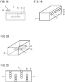
- a bottom face of the treatment solution regeneration bath is inclined.
- insoluble iron (II) oxalate is generated.
- the iron (II) oxalate forms precipitate and settles inside the treatment solution regeneration bath. If the bottom face of the treatment solution regeneration bath is inclined, the precipitate accumulates at a lower location of the inclined bottom face. In this case, it is easy to recover the precipitate.
- the treatment solution regeneration bath may be partitioned into a light irradiation chamber and a sedimentation chamber by a partition member.
- the partition member has an opening portion that connects the light irradiation chamber and the sedimentation chamber.
- the one or more light source members are disposed in the light irradiation chamber.
- the treatment solution regeneration bath is partitioned into a light irradiation chamber and a sedimentation chamber, light irradiation and removal of precipitate can be performed in separate compartments. In this case, removal of the precipitate can be performed more efficiently.
- the bottom face of the light irradiation chamber becomes lower in the direction from the light irradiation chamber toward the sedimentation chamber.
- the treatment solution regeneration bath further includes a current direction changing member.
- the current direction changing member is disposed so as to be immersible in the oxalate treatment solution in the treatment solution regeneration bath, and changes a direction of a flow of the oxalate treatment solution in the treatment solution regeneration bath.
- the treatment solution regeneration bath includes a current direction changing member, the directions of flows of the oxalate treatment solution in the treatment solution regeneration bath need not be uniformly aligned in a fixed direction, and a turbulent flow can easily be generated. If a turbulent flow is generated, the amount of oxalate treatment solution to be irradiated with light increases. Therefore, the oxalate treatment solution can be subjected to regeneration treatment more efficiently.
- the light radiation apparatus is an ultraviolet radiation apparatus.
- the oxalate treatment solution can be regenerated more efficiently.
- wavelength in the ultraviolet range refers to a wavelength in the range of 10 to 400 nm.
- a method for producing a chemically treated alloy material of the present embodiment includes a chemical treatment step and a treatment solution regeneration step.
- a chemical treatment step an alloy material is immersed in an oxalate treatment solution containing oxalate ions and fluorine ions to perform a chemical treatment.
- the treatment solution regeneration step light is radiated to the oxalate treatment solution during the chemical treatment and/or the oxalate treatment solution after the chemical treatment.
- the method for producing a chemically treated alloy material of the present embodiment uses, for example, the following chemical treatment solution regeneration apparatus.
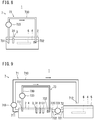
- FIG. 3 is a schematic diagram of one example of a chemical treatment solution regeneration apparatus 1 that is used in the method for producing a chemically treated alloy material according to the present embodiment.
- the chemical treatment solution regeneration apparatus 1 includes a treatment solution regeneration bath 2 and a light radiation apparatus 3.
- the treatment solution regeneration bath 2 is capable of containing an oxalate treatment solution 4 during chemical treatment of an alloy material 6 or after chemical treatment of the alloy material 6.
- the treatment solution regeneration bath 2 is a casing.
- the top face of the treatment solution regeneration bath 2 may be open, or a top plate may be provided at the top face. At least one part of a top plate or a side face may be a member having translucency.
- the shape of the treatment solution regeneration bath 2 is not particularly limited as long as the treatment solution regeneration bath 2 is capable of containing the oxalate treatment solution 4 during chemical treatment or after chemical treatment of the alloy material 6.
- the shape of the treatment solution regeneration bath 2 may be a rectangular parallelepiped shape, a cubic shape or a pipe shape.
- the oxalate treatment solution 4 which the treatment solution regeneration bath 2 contains includes oxalate ions and fluorine ions.
- the alloy material 6 may be immersed in the treatment solution regeneration bath 2, and regeneration of the oxalate treatment solution 4 in the treatment solution regeneration bath 2 and chemical treatment of the alloy material 6 may be performed at the same time.
- the chemical treatment solution regeneration apparatus 1 may function as a chemical treatment apparatus for performing chemical treatment of the alloy material 6.
- the treatment solution regeneration bath 2 contains the oxalate treatment solution 4 during chemical treatment of the alloy material 6.
- the treatment solution regeneration bath 2 contains the oxalate treatment solution 4 after chemical treatment of the alloy material 6.
- the oxalate treatment solution 4 which the treatment solution regeneration bath 2 contains may be a mixture of the oxalate treatment solution 4 during chemical treatment of the alloy material 6 and the oxalate treatment solution 4 after chemical treatment of the alloy material 6. Further, as described later, in the case of performing a chemical treatment in the treatment solution regeneration bath 2, in addition to the oxalate treatment solution 4, the treatment solution regeneration bath 2 is also capable of containing the alloy material 6 that is the object of the chemical treatment.
- the light radiation apparatus 3 includes a light source member 31 and an unshown power supply apparatus. At least one part of the light source member 31 is disposed inside the treatment solution regeneration bath 2 or in the vicinity of the outside of the treatment solution regeneration bath 2.
- the light source member 31 radiates light at the oxalate treatment solution 4.
- the light radiation apparatus 3 radiates light at the oxalate treatment solution 4 during chemical treatment or after chemical treatment to thereby regenerate the oxalate treatment solution 4.
- the light radiation apparatus 3 is disposed in a manner so that the light radiation apparatus 3 is capable of radiating light at the oxalate treatment solution 4 in the treatment solution regeneration bath 2.
- the light source member 31 of the light radiation apparatus 3 may be disposed inside the treatment solution regeneration bath 2, as illustrated in FIG. 3 , or may be disposed on the outside of the treatment solution regeneration bath 2.
- the light source member 31 is disposed inside the treatment solution regeneration bath 2 although the light source member 31 may be fixed without being immersed in the oxalate treatment solution 4, it is preferable that the light source member 31 is disposed in a manner in which at least one part thereof is immersible in the oxalate treatment solution 4 in the treatment solution regeneration bath 2, and a configuration in which all of the light source member 31 is immersed in the oxalate treatment solution 4 is more preferable.
- the light radiated from the light source member 31 is attenuated when propagating through the atmosphere or through a member having translucency.
- the distance between the light source and the oxalate treatment solution 4 is shortened. Therefore, stronger light can be radiated to the oxalate treatment solution 4.
- the oxalate treatment solution 4 can be subjected to regeneration treatment more efficiently.
- a method for immersing the light source member 31 in the oxalate treatment solution 4 is not particularly limited.
- the light source member 31 may be fixed, and a predetermined amount of the oxalate treatment solution 4 may be filled into the treatment solution regeneration bath 2 so as to immerse at least one part of the light source member 31 in the oxalate treatment solution 4.
- the light radiation apparatus 3 may also include a driving source that moves the light source member 31 in the vertical direction and/or horizontal direction, and by moving the light source member 31 by means of the driving source, the light source member 31 may be immersed in the oxalate treatment solution 4 that was already filled in the treatment solution regeneration bath 2.
- the light source member 31 may be disposed, for example, at a position in the treatment solution regeneration bath 2 that is a position above the oxalate treatment solution 4. Specifically, in a case where a top plate is attached to the treatment solution regeneration bath 2, the light source member 31 may be attached to the surface on the oxalate treatment solution 4 side of the top plate. In a case where a top plate is not attached to the treatment solution regeneration bath 2, the light source member 31 may be disposed at a position above the oxalate treatment solution 4 that is a position on the inner side of a side face of the treatment solution regeneration bath 2.
- the number, size and shape of the light source members 31 are not particularly limited.
- the number of the light source members 31 may be one, as illustrated in FIG. 3 , or may be more than one.
- the alloy material 6 is immersed in the oxalate treatment solution 4 containing oxalate ions and fluorine ions to perform a chemical treatment.
- the oxalate treatment solution 4 is prepared and inserted into the treatment solution regeneration bath 2.
- the oxalate treatment solution 4 contains oxalate ions and fluorine ions.
- the oxalate treatment solution 4 is produced by dissolving oxalic acid or a salt having an oxalate ion as an anion, and a salt having a fluorine ion as an anion in a solvent.
- a salt having an oxalate ion as an anion include one or two or more types selected from the group consisting of sodium oxalate, ammonium oxalate, potassium oxalate and iron (III) oxalate.
- Examples of a salt having a fluorine ion as an anion include one or two or more types selected from the group consisting of sodium bifluoride, sodium fluoride, ammonium fluoride, potassium fluoride, hydrogen fluoride, hydrofluoric acid and nitrogen fluoride.
- the solvent may be, for example, water or a mixed solution of water and an organic solvent.
- the organic solvent is, for example, an organic solvent that is compatible with water.
- the oxalate ion content of the oxalate treatment solution 4 is, for example, 1.0 to 50 g/L.
- a lower limit of the oxalate ion content of the oxalate treatment solution 4 is preferably 5.0 g/L.
- An upper limit of the oxalate ion content of the oxalate treatment solution 4 is preferably 30 g/L.
- the fluorine ion content of the oxalate treatment solution 4 is, for example, 0.1 to 10 g/L.
- a lower limit of the fluorine ion content of the oxalate treatment solution 4 is preferably 1.0 g/L.
- An upper limit of the fluorine ion content of the oxalate treatment solution 4 is preferably 5.0 g/L.
- the alloy material 6 is immersed in the oxalate treatment solution 4.
- the oxalate treatment solution 4 contains oxalate ions, fluorine ions and a solvent.
- the oxalate treatment solution 4 may also contain other components.
- the oxalate treatment solution 4 also contains an oxidizing agent.
- the oxidizing agent is, for example, nitrate ions.
- An oxidation reaction of hydrogen is promoted by nitrate ions.
- the oxidized hydrogen disperses in the oxalate treatment solution 4 as water.
- Nitrate ions can be contained in the oxalate treatment solution 4 by dissolving nitric acid or a salt having a nitrate ion as an anion in the oxalate treatment solution 4.
- Examples of a salt having a nitrate ion as an anion include one or two or more types selected from the group consisting of ammonium nitrate, potassium nitrate, calcium nitrate, iron nitrate, copper nitrate and sodium nitrate.
- the oxidizing agent may contain one or two or more types of substance selected from the group consisting of permanganate and peroxide.
- the content of the oxidizing agent in the oxalate treatment solution 4 is, for example, 0.1 to 20 g/L.
- An upper limit of the content of the oxidizing agent in the oxalate treatment solution 4 is preferably 10 g/L.
- the oxalate treatment solution 4 further contains an accelerating agent.
- the accelerating agent is, for example, thiosulfate ions.
- the thiosulfate ions react with dissolved oxygen in the oxalate treatment solution 4 and decompose into sulfuric acid. By this means, the amount of dissolved oxygen in the oxalate treatment solution 4 is reduced and the chemical treatment is accelerated.
- Thiosulfate ions can be contained in the oxalate treatment solution 4 by dissolving a salt having a thiosulfate ion as an anion in the oxalate treatment solution 4.
- Examples of a salt having a thiosulfate ion as an anion include one or two or more types selected from the group consisting of sodium thiosulfate, ammonium thiosulfate, potassium thiosulfate and calcium thiosulfate.
- the content of the accelerating agent in the oxalate treatment solution 4 is, for example, 1.0 to 50 g/L.
- a lower limit of the content of the accelerating agent in the oxalate treatment solution 4 is preferably 10 g/L.
- An upper limit of the content of the accelerating agent in the oxalate treatment solution 4 is preferably 40 g/L.
- the chemical treatment is a well-known chemical treatment.
- the temperature and time period of the chemical treatment can be appropriately set.
- the temperature of the chemical treatment is within the range of 40 to 100°C.
- a lower limit of the temperature of the chemical treatment is preferably 80°C.
- An upper limit of the temperature of the chemical treatment is preferably 95°C.
- the time period of the chemical treatment is within the range of 1 to 200 minutes.
- a lower limit of the time period of the chemical treatment is preferably five minutes.
- An upper limit of the time period of the chemical treatment is preferably 20 minutes.
- the inside of the treatment solution regeneration bath 2 may be stirred during the chemical treatment or need not be stirred.
- the temperature of the chemical treatment may be adjusted by heating the treatment solution regeneration bath 2, or may be adjusted by immersing a heat source inside the treatment solution regeneration bath 2.
- the temperature of the chemical treatment may be adjusted by adding the oxalate treatment solution 4 that was heated using an unshown heating apparatus into the treatment solution regeneration bath 2.
- the light radiation apparatus 3 is used to radiate light at the oxalate treatment solution 4 during chemical treatment and/or the oxalate treatment solution 4 after chemical treatment.
- the oxalate treatment solution 4 in the treatment solution regeneration bath 2 contains iron ions, oxalate ions and fluorine ions.
- iron ions When light is radiated to the oxalate treatment solution 4, iron ions are reduced and fluorine ions are released. By this means, the etching action of fluorine ions is restored.
- formation of iron (II) oxalate is accelerated.
- the iron ion content of the oxalate treatment solution 4 decreases.
- the iron ion content decreases, it becomes difficult to form complexes between iron ions and fluorine ions. Therefore, the action of the fluorine ions is more actively maintained. As a result, a decrease in the chemical treatability can be suppressed even in a case where chemical treatment is repeatedly performed.
- the production method described above may also include an oxalate ion addition step.
- oxalate ions are consumed as the iron ion content of the oxalate treatment solution 4 decreases.
- the production method includes a step of adding oxalate ions, consumed oxalate ions are replenished.
- Addition of oxalate ions is performed by dissolving oxalic acid or a salt having an oxalate ion as an anion in the oxalate treatment solution 4.
- the addition of oxalate ions is performed by adding a solution in which oxalate ions were dissolved to the oxalate treatment solution 4.
- Examples of salts having an oxalate ion as an anion include one or two or more types of salt selected from the group consisting of sodium oxalate, ammonium oxalate, potassium oxalate and iron (III) oxalate.
- the oxalate ion content of the oxalate treatment solution 4 increases.
- the concentration of the added oxalate ions can be appropriately set.
- the time point at which to perform the oxalate ion addition step is not particularly limited.
- the oxalate ion addition step may be performed before the chemical treatment step, may be performed during the chemical treatment step, or may be performed after the chemical treatment.
- the oxalate ion addition step may be performed at a time point that is after the chemical treatment and before the treatment solution regeneration step, or may be performed during the treatment solution regeneration step, or may be performed after the treatment solution regeneration step.
- the production method described above may also include a preparation step of preparing the alloy material 6 before the chemical treatment step.
- preparation refers to, for example, shotblasting, pickling or degreasing.
- a lubrication coating may be formed on the surface of the chemically treated alloy material produced by the above described production method.
- the lubrication coating is, for example, metallic soap.
- wavelengths of the light in the treatment solution regeneration step are short wavelengths of high intensity
- the decomposition reaction of iron (III) oxalate to iron (II) oxalate is further accelerated. Therefore, preferably the wavelengths of the light include a wavelength in the ultraviolet range. If the wavelengths of the light include a wavelength in the ultraviolet range, an etching action of fluorine ions can be restored more efficiently, and the iron ion content of the oxalate treatment solution 4 can be reduced more efficiently.
- the term "wavelength in the ultraviolet range” refers to a wavelength in the range of 10 to 400 nm.
- the shape of the alloy material 6 is not particularly limited as long as the shape is such that an oxalate coating can be formed.
- the shape of the alloy material 6 is, for example, the shape of a plate, a pipe, a bar, a wire rod, a sphere, die steel, another alloy material for construction or a machine construction component, a gear, a connecting rod, a crankshaft, a piston or another automobile component.
- the method for producing a chemically treated alloy material of the present embodiment can be favorably applied to a case where the shape of the alloy material 6 is a pipe shape.
- the chemical composition of the alloy material 6 contains Fe. It suffices that the chemical composition of the alloy material 6 contains Fe. That is, the alloy material 6 may be a steel material that contains 50% or more of Fe. In this case, the alloy material 6 may contain 10.5% or more of Cr. An oxide film that has high corrosion resistance is formed on the surface of the alloy material 6 that contains 10.5% or more of Cr. According to the method for producing a chemically treated alloy material of the present embodiment, the action of fluorine ions is actively maintained. Therefore, a chemically treated alloy material can be produced even when using the alloy material 6 having an oxide film formed on the surface. The method for producing a chemically treated alloy material of the present embodiment can be favorably used for the alloy material 6 that contains 10.5% or more of Cr.
- the alloy material 6 may be, for example, an Ni-based alloy or an Ni-Cr-Fe alloy.
- the method for producing a chemically treated alloy material of the present embodiment can also be favorably used for the alloy material 6 in which the total content of Cr and/or Ni is more than 50% (that is, the alloy material 6 in which the Fe content is less than 50%).
- the oxalate treatment solution 4 is radiated to the oxalate treatment solution 4 while causing the oxalate treatment solution 4 in the treatment solution regeneration bath 2 to flow.
- the amount of the oxalate treatment solution 4 to be irradiated with light increases.
- the oxalate treatment solution 4 can be subjected to regeneration treatment more efficiently, and hence a decrease in chemical treatability can be suppressed more efficiently.
- the treatment solution regeneration step can be executed while causing the oxalate treatment solution 4 to flow.
- the chemical treatment solution regeneration apparatus 1 further includes a flow mechanism that causes the oxalate treatment solution 4 in the treatment solution regeneration bath 2 to flow.
- FIG. 4 is a schematic diagram of a chemical treatment solution regeneration apparatus 1 according to another embodiment that is different from FIG. 3 .
- the chemical treatment solution regeneration apparatus 1 includes a flow mechanism 7.
- the flow mechanism 7 is an apparatus that is attached to a rotary shaft, and generates a flow in the rotary shaft direction by rotation of a blade having a helicoidal surface around the rotary shaft.
- the flow mechanism 7 is, for example, a screw or a propeller.
- the flow mechanism 7 may be another kind of mechanism.
- the flow mechanism 7, for example, may be a mechanism that causes the oxalate treatment solution 4 to circulate.
- the flow mechanism 7 for example, may be a mechanism that utilizes a pump to pump up some of the oxalate treatment solution 4 in the treatment solution regeneration bath 2, and returns the pumped-up oxalate treatment solution 4 into the treatment solution regeneration bath 2 utilizing a height difference.
- the flow mechanism 7, for example may be a mechanism that includes a heating apparatus inside the treatment solution regeneration bath 2, and causes the oxalate treatment solution 4 which was heated by the heating apparatus to flow by convection.
- the number and arrangement of flow mechanisms 7 is not particularly limited.
- the number of flow mechanisms 7 may be one or may be more than one.
- a direction in which the oxalate treatment solution 4 is caused to flow by the flow mechanism 7 may be the horizontal direction, may be a perpendicular direction from above to below, may be a perpendicular direction from below to above, or may be a direction that is inclined with respect to the horizontal direction.
- the oxalate treatment solution 4 may be caused to flow in one direction by the flow mechanism 7, or flows of the oxalate treatment solution 4 in different directions may be generated by flow mechanisms 7 that are oriented in different directions. In short, it suffices that the amount of the oxalate treatment solution 4 to be irradiated with light from the light source member 31 can be increased. Accordingly, directions in which the oxalate treatment solution 4 is caused to flow by the flow mechanism 7 include at least a direction toward the light source member 31.
- the chemical treatment step is the same as in the first embodiment.
- the oxalate treatment solution 4 in the treatment solution regeneration bath 2 is caused to flow by the flow mechanism 7.
- the method for producing a chemically treated alloy material of the present disclosure can also be implemented by an apparatus other than the apparatuses illustrated in FIG. 3 and FIG. 4 .
- the chemical treatment solution regeneration apparatus 1 examples of the chemical treatment solution regeneration apparatus 1 that are capable of implementing the method for producing a chemically treated alloy material of the present disclosure are described.
- the chemical treatment solution regeneration apparatus 1 may have a chemical treatment bath 5 in addition to the treatment solution regeneration bath 2. In such case, chemical treatment of the alloy material 6 and regeneration treatment of the oxalate treatment solution 4 are performed in separate baths.
- the chemical treatment solution regeneration apparatus 1 includes the chemical treatment bath 5 that is separate from the treatment solution regeneration bath 2, the flow mechanism 7 may have a first liquid supply channel and a second liquid supply channel.
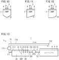
- FIG. 5 is a schematic diagram of the chemical treatment solution regeneration apparatus 1 according to another embodiment that is different to the embodiments illustrated in FIG. 3 and FIG. 4 . The arrows in FIG. 5 indicate the direction in which the oxalate treatment solution 4 circulates. Referring to FIG.
- the chemical treatment solution regeneration apparatus 1 includes the treatment solution regeneration bath 2, the light radiation apparatus 3, the chemical treatment bath 5 and the flow mechanism 7.
- the flow mechanism 7 includes a first liquid supply channel 71 that conveys the oxalate treatment solution 4 in the treatment solution regeneration bath 2 to the chemical treatment bath 5, and a second liquid supply channel 72 that conveys the oxalate treatment solution 4 in the chemical treatment bath 5 to the treatment solution regeneration bath 2.
- the chemical treatment solution regeneration apparatus 1 circulates the oxalate treatment solution 4 between the chemical treatment bath 5 and the treatment solution regeneration bath 2 by means of the first liquid supply channel 71 and the second liquid supply channel 72.
- the chemical treatment bath 5 is capable of containing the oxalate treatment solution 4 after being irradiated with light by the light radiation apparatus 3 in the treatment solution regeneration bath 2.
- a chemical treatment in which the alloy material 6 is immersed in the oxalate treatment solution 4 contained therein can be performed.
- the chemical treatment bath 5 has a rectangular parallelepiped-shaped casing.
- the top face of the chemical treatment bath 5 may be open, or a top plate may be provided at the top face.
- the shape of the chemical treatment bath 5 may be a rectangular parallelepiped shape, a cubic shape, or the shape of a casing that has a circular bottom face like a bucket. Further, the number of chemical treatment baths 5 is not particularly limited.
- the first liquid supply channel 71 connects the treatment solution regeneration bath 2 and the chemical treatment bath 5, and conveys the oxalate treatment solution 4 from the treatment solution regeneration bath 2 to the chemical treatment bath 5.
- the first liquid supply channel 71 includes a first liquid supply channel main body 710, a treatment-solution-regeneration-bath-side inflow port 711 that is formed at one of the end portions of the first liquid supply channel main body 710, and a chemical-treatment-bath-side discharge port 712 that is formed at the other end portion of the first liquid supply channel main body 710.
- the first liquid supply channel 71 may further include a first liquid supply channel driving source 713.
- the shape of the first liquid supply channel main body 710 is, for example, tubular.
- a filter for collecting precipitate, or a valve that inhibits a back flow of the oxalate treatment solution 4 may be provided inside the first liquid supply channel main body 710.
- the treatment-solution-regeneration-bath-side inflow port 711 is formed at an end portion on the treatment solution regeneration bath 2 side of the first liquid supply channel main body 710.
- the treatment-solution-regeneration-bath-side inflow port 711 allows the oxalate treatment solution 4 in the treatment solution regeneration bath 2 to flow into the first liquid supply channel main body 710.
- the treatment-solution-regeneration-bath-side inflow port 711 is disposed further downstream than the center position of the treatment solution regeneration bath 2.
- a filter for inhibiting the flow of precipitate or other foreign substances into the first liquid supply channel main body 710 may be provided in the treatment-solution-regeneration-bath-side inflow port 711.
- the chemical-treatment-bath-side discharge port 712 is formed at an end portion on the chemical treatment bath 5 side of the first liquid supply channel main body 710.
- the chemical-treatment-bath-side discharge port 712 discharges the oxalate treatment solution 4 in the first liquid supply channel main body 710 into the chemical treatment bath 5.
- the chemical-treatment-bath-side discharge port 712 is disposed further upstream than the center position of the chemical treatment bath 5. In this case, the oxalate treatment solution 4 in the chemical treatment bath 5 can be caused to circulate more efficiently.
- the first liquid supply channel driving source 713 causes the oxalate treatment solution 4 in the first liquid supply channel main body 710 to move from the treatment-solution-regeneration-bath-side inflow port 711 to the chemical-treatment-bath-side discharge port 712.
- the first liquid supply channel driving source 713 is not particularly limited as long as the first liquid supply channel driving source 713 is capable of moving the oxalate treatment solution 4.
- the first liquid supply channel driving source 713 is, for example, a pump.
- the second liquid supply channel 72 connects the chemical treatment bath 5 and the treatment solution regeneration bath 2, and conveys the oxalate treatment solution 4 from the chemical treatment bath 5 to the treatment solution regeneration bath 2.
- the second liquid supply channel 72 includes a second liquid supply channel main body 720, a chemical-treatment-bath-side inflow port 721 that is formed at one of the end portions of the second liquid supply channel main body 720, and a treatment-solution-regeneration-bath-side discharge port 722 that is formed at the other end portion of the second liquid supply channel main body 720.
- the second liquid supply channel 72 may further include a second liquid supply channel driving source 723.
- the shape of the second liquid supply channel main body 720 is, for example, tubular.
- a filter for collecting precipitate or other foreign substances, or a valve that inhibits a back flow of the oxalate treatment solution 4 may be provided inside the second liquid supply channel main body 720.
- the chemical-treatment-bath-side inflow port 721 is formed at an end portion on the chemical treatment bath 5 side of the second liquid supply channel main body 720.
- the chemical-treatment-bath-side inflow port 721 allows the oxalate treatment solution 4 in the chemical treatment bath 5 to flow into the second liquid supply channel main body 720.
- the chemical-treatment-bath-side inflow port 721 is disposed further downstream than the center position of the chemical treatment bath 5. In this case, the oxalate treatment solution 4 in the chemical treatment bath 5 can be caused to circulate more efficiently.
- the treatment-solution-regeneration-bath-side discharge port 722 is formed at an end portion on the treatment solution regeneration bath 2 side of the second liquid supply channel main body 720.
- the treatment-solution-regeneration-bath-side discharge port 722 discharges the oxalate treatment solution 4 in the second liquid supply channel main body 720 into the treatment solution regeneration bath 2.
- the treatment-solution-regeneration-bath-side discharge port 722 is disposed further upstream than the center position of the treatment solution regeneration bath 2.
- the second liquid supply channel driving source 723 causes the oxalate treatment solution 4 in the second liquid supply channel main body 720 to move from the chemical-treatment-bath-side inflow port 721 to the treatment-solution-regeneration-bath-side discharge port 722.
- the second liquid supply channel driving source 723 is not particularly limited as long as the second liquid supply channel driving source 723 is capable of moving the oxalate treatment solution 4.
- the second liquid supply channel driving source 723 is, for example, a pump.
- the first liquid supply channel 71 may be connected to each of the plurality of chemical treatment baths 5, and may convey the oxalate treatment solution 4 in the treatment solution regeneration bath 2 to each of the chemical treatment baths 5. Further, as described later, a single first liquid supply channel 71 that is connected to the treatment solution regeneration bath 2 may branch at a position along the single first liquid supply channel 71 and convey the oxalate treatment solution 4 to each of the chemical treatment baths 5. The same applies with respect to the second liquid supply channel 72.
- the second liquid supply channel 72 may be connected to each of the chemical treatment baths 5, and the oxalate treatment solution 4 from the respective chemical treatment baths 5 may be conveyed to the same treatment solution regeneration bath 2.
- a configuration may also be adopted in which second liquid supply channels 72 that are connected to the respective chemical treatment baths 5 merge at a partway position.
- the first liquid supply channel driving source 713 is disposed on the first liquid supply channel 71
- the second liquid supply channel driving source 723 is disposed on the second liquid supply channel 72.
- the number and arrangement of the first liquid supply channel driving source 713 and the second liquid supply channel driving source 723 are not limited to the example illustrated in FIG. 5 .
- either one of the first liquid supply channel driving source 713 and the second liquid supply channel driving source 723 need not be provided.
- the first liquid supply channel driving source 713 or the second liquid supply channel driving source 723 may be disposed only on the liquid supply channel which has the lowest place among the entire first liquid supply channel 71 or the entire second liquid supply channel 72.
- the oxalate treatment solution 4 that was irradiated with light within the treatment solution regeneration bath 2 is conveyed by the first liquid supply channel 71 to the chemical treatment bath 5.
- chemical treatment can be carried out utilizing the oxalate treatment solution 4 that underwent regeneration treatment.
- the oxalate treatment solution 4 which deteriorated inside the chemical treatment bath 5 is conveyed by the second liquid supply channel 72 to the treatment solution regeneration bath 2.
- the oxalate treatment solution 4 is regenerated by light irradiation.
- the oxalate treatment solution 4 that underwent the regeneration treatment is conveyed once more by the first liquid supply channel 71 to the chemical treatment bath 5.
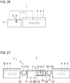
- FIG. 6 is a schematic diagram of the chemical treatment solution regeneration apparatus 1 according to another embodiment that is different from FIG. 3 to FIG. 5 .
- the light source member 31 of the light radiation apparatus 3 is disposed at a position such that one part thereof is immersed in the oxalate treatment solution 4 in the treatment solution regeneration bath 2, in FIG. 6 the light source member 31 is disposed in the vicinity of the outside of the treatment solution regeneration bath 2.
- the method for producing a chemically treated alloy material of the present disclosure can also be carried out using the chemical treatment solution regeneration apparatus 1 that includes the chemical treatment bath 5, the first liquid supply channel 71 and the second liquid supply channel 72.
- the oxalate treatment solution 4 is caused to circulate between the treatment solution regeneration bath 2 and the chemical treatment bath 5 using the first liquid supply channel 71 and the second liquid supply channel 72.
- the chemical treatment baths 5 may include a first chemical treatment bath 51 and a second chemical treatment bath 52.
- a discharge port switching mechanism and an inflow port switching mechanism may be used to switch between the oxalate treatment solutions 4 in the chemical treatment baths to be circulated.
- the oxalate treatment solutions 4 in the first chemical treatment bath 51 and the second chemical treatment bath 52 can be caused to circulate in an alternating manner.
- FIG. 7 is a schematic diagram of the chemical treatment solution regeneration apparatus 1 according to another embodiment that is different from FIG. 3 to FIG. 6 .
- the first liquid supply channel main body 710 may include two end portions on the chemical treatment bath 5 side.
- a discharge port is formed at the two end portions on the chemical treatment bath 5 side of the first liquid supply channel main body 710.
- the first liquid supply channel 71 includes the first liquid supply channel main body 710, a first chemical-treatment-bath-side discharge port 714 and a second chemical-treatment-bath-side discharge port 715.
- the first chemical-treatment-bath-side discharge port 714 is formed at one of the end portions on the chemical treatment bath 5 side of the first liquid supply channel main body 710, and discharges the oxalate treatment solution 4 in the first liquid supply channel main body 710 into the first chemical treatment bath 51.
- the second chemical-treatment-bath-side discharge port 715 is formed at the other end portion on the chemical treatment bath 5 side of the first liquid supply channel main body 710, and discharges the oxalate treatment solution 4 in the first liquid supply channel main body 710 into the second chemical treatment bath 52.
- the two end portions on the chemical treatment bath 5 side of the first liquid supply channel 71 may be formed in a manner in which the first liquid supply channel main body 710 branches at a partway position as illustrated in FIG. 7 , or a configuration may be adopted in which two of the first liquid supply channels 71 are provided, and the two end portions are the end portions of the two first liquid supply channels 71, respectively.
- the second liquid supply channel main body 720 may include two end portions on the chemical treatment bath 5 side.
- An inflow port is formed at each of the two end portions on the chemical treatment bath 5 side of the second liquid supply channel main body 720.
- the second liquid supply channel 72 includes the second liquid supply channel main body 720, a first chemical-treatment-bath-side inflow port 724 and a second chemical-treatment-bath-side inflow port 725.
- the first chemical-treatment-bath-side inflow port 724 is formed at one of the end portions on the chemical treatment bath 5 side of the second liquid supply channel main body 720, and allows the oxalate treatment solution 4 in the first chemical treatment bath 51 to flow into the second liquid supply channel main body 720.
- the second chemical-treatment-bath-side inflow port 725 is formed at the other of the end portions on the chemical treatment bath 5 side of the second liquid supply channel main body 720, and allows the oxalate treatment solution 4 in the second chemical treatment bath 52 to flow into the second liquid supply channel main body 720.
- the two end portions of the second liquid supply channel 72 may be formed in a manner in which the second liquid supply channel main body 720 branches at a partway position as illustrated in FIG. 7 , or a configuration may be adopted in which two of the second liquid supply channels 72 are provided, and the two end portions are the end portions of the two second liquid supply channels 72, respectively.
- the flow mechanism 7 also includes a discharge port switching mechanism 716 and an inflow port switching mechanism 726.
- the discharge port switching mechanism 716 switches whether to cause the oxalate treatment solution 4 in the first liquid supply channel main body 710 to be discharged from the first chemical-treatment-bath-side discharge port 714 or from the second chemical-treatment-bath-side discharge port 715.
- the inflow port switching mechanism 726 switches whether to cause the oxalate treatment solution 4 to flow into the second liquid supply channel main body 720 from the first chemical-treatment-bath-side inflow port 724 or from the second chemical-treatment-bath-side inflow port 725.
- the discharge port switching mechanism 716 and the inflow port switching mechanism 726 are not particularly limited as long as a flow of the oxalate treatment solution 4 can be switched.
- the discharge port switching mechanism 716 is, for example, a valve. Referring to FIG. 7 , two valves are provided that are disposed on the first chemical treatment bath 51 side and on the second chemical treatment bath 52 side on the branched first liquid supply channel main body 710, respectively.
- the discharge port switching mechanism 716 may also be a pump. In this case, the first liquid supply channel driving source 713 (pump) is not required.
- the inflow port switching mechanism 726 is, for example, a valve. Referring to FIG. 7 , two valves are provided that are disposed on the first chemical treatment bath 51 side and on the second chemical treatment bath 52 side on the branched second liquid supply channel main body 720, respectively.
- the inflow port switching mechanism 726 may also be a pump. In this case, the second liquid supply channel driving source 723 (pump) is not required.
- the chemical treatment solution regeneration apparatus 1 includes the chemical treatment bath 5, and the flow mechanism 7 causes the oxalate treatment solution 4 as a whole to circulate between the chemical treatment bath 5 and the treatment solution regeneration bath 2.
- the flow mechanism 7 causes the oxalate treatment solution 4 in the treatment solution regeneration bath 2 to circulate.
- FIG. 8 is a schematic diagram of the chemical treatment solution regeneration apparatus 1 according to another embodiment that is different from FIG. 3 to FIG. 7 .
- the chemical treatment solution regeneration apparatus 1 includes the treatment solution regeneration bath 2, the light radiation apparatus 3 and the flow mechanism 7.
- the flow mechanism 7 includes an under-regeneration-treatment-solution circulation channel 73 that causes the oxalate treatment solution 4 within the treatment solution regeneration bath 2 to circulate.
- the under-regeneration-treatment-solution circulation channel 73 includes an under-regeneration-treatment-solution circulation channel main body 730, an under-regeneration-treatment-solution inflow port 731 and an under-regeneration-treatment-solution discharge port 732. At least one light source member 31 is disposed between the under-regeneration-treatment-solution inflow port 731 and the under-regeneration-treatment-solution discharge port 732.
- the under-regeneration-treatment-solution circulation channel 73 also includes an under-regeneration-treatment-solution circulation driving source 733.
- the oxalate treatment solution 4 in the treatment solution regeneration bath 2 is caused to repeatedly flow from the under-regeneration-treatment-solution discharge port 732 toward the under-regeneration-treatment-solution inflow port 731. Therefore, the occasions at which the oxalate treatment solution 4 is irradiated with light from the light source member 31 that is disposed between the under-regeneration-treatment-solution discharge port 732 and the under-regeneration-treatment-solution inflow port 731 increase. As a result, the oxalate treatment solution 4 can be subjected to regeneration treatment more efficiently.
- the shape of the under-regeneration-treatment-solution circulation channel main body 730 is not particularly limited.
- the shape of the under-regeneration-treatment-solution circulation channel main body 730 is, for example, tubular.
- a filter for collecting precipitate or other foreign substances, or a valve that inhibits a back flow of the oxalate treatment solution 4 may be provided in the under-regeneration-treatment-solution circulation channel main body 730.
- the under-regeneration-treatment-solution inflow port 731 is formed at one of the end portions of the under-regeneration-treatment-solution circulation channel main body 730, and allows the oxalate treatment solution 4 in the treatment solution regeneration bath 2 to flow into the under-regeneration-treatment-solution circulation channel main body 730.
- a filter for inhibiting precipitate from flowing into the under-regeneration-treatment-solution circulation channel main body 730, or a valve that inhibits a back flow of the oxalate treatment solution 4 may be provided in the under-regeneration-treatment-solution inflow port 731.
- the under-regeneration-treatment-solution discharge port 732 is formed at the other end portion of the under-regeneration-treatment-solution circulation channel main body 730, and discharges the oxalate treatment solution 4 that is in the under-regeneration-treatment-solution circulation channel main body 730.
- the under-regeneration-treatment-solution discharge port 732 may be disposed so as to be immersible in the oxalate treatment solution 4 in the treatment solution regeneration bath 2 as illustrated in FIG.
- the under-regeneration-treatment-solution discharge port 732 may be disposed in a manner in which the under-regeneration-treatment-solution discharge port 732 is connected to the hole, or the under-regeneration-treatment-solution discharge port 732 may be disposed above the treatment solution regeneration bath 2.
- an ejection nozzle for increasing the discharge speed of the oxalate treatment solution 4 may be provided in the under-regeneration-treatment-solution discharge port 732.
- the under-regeneration-treatment-solution circulation driving source 733 causes the oxalate treatment solution 4 in the under-regeneration-treatment-solution circulation channel main body 730 to move from the under-regeneration-treatment-solution inflow port 731 to the under-regeneration-treatment-solution discharge port 732.
- the under-regeneration-treatment-solution circulation driving source 733 is, for example, a pump.
- At least one light source member 31 is disposed between the under-regeneration-treatment-solution discharge port 732 and the under-regeneration-treatment-solution inflow port 731.
- a plurality of the light source members 31 are disposed, preferably all of the light source members 31 are disposed between the under-regeneration-treatment-solution discharge port 732 and the under-regeneration-treatment-solution inflow port 731.
- the amount of the oxalate treatment solution 4 to be irradiated with light while the oxalate treatment solution 4 flows from the under-regeneration-treatment-solution discharge port 732 to the under-regeneration-treatment-solution inflow port 731 increases.
- the number of under-regeneration-treatment-solution circulation channels 73 is not particularly limited.
- One under-regeneration-treatment-solution circulation channel 73 may be provided as illustrated in FIG. 8 , or a plurality of the under-regeneration-treatment-solution circulation channels 73 may be provided.
- the direction in which the oxalate treatment solution 4 is circulated may be the same or different for each of the under-regeneration-treatment-solution circulation channels 73.
- the respective under-regeneration-treatment-solution circulation channels 73 may operate simultaneously or may operate at different times from each other.
- the chemical treatment solution regeneration apparatus 1 may have a configuration in which the chemical treatment bath 5 is provided in addition to the treatment solution regeneration bath 2, and chemical treatment of the alloy material 6 and regeneration treatment of the oxalate treatment solution 4 can be performed separately to each other.
- the chemical treatment solution regeneration apparatus 1 includes the under-regeneration-treatment-solution circulation channel 73 which causes the oxalate treatment solution 4 in the treatment solution regeneration bath 2 to circulate, and the first liquid supply channel 71 and the second liquid supply channel 72 which cause the entire oxalate treatment solution 4 to circulate, including the oxalate treatment solution 4 in the chemical treatment bath 5.
- FIG. 9 is a schematic diagram of the chemical treatment solution regeneration apparatus 1 according to another embodiment that is different from FIG. 3 to FIG. 8 .
- the chemical treatment solution regeneration apparatus 1 includes the treatment solution regeneration bath 2, the light radiation apparatus 3, the chemical treatment bath 5 and the flow mechanism 7.
- the flow mechanism 7 includes the first liquid supply channel 71, the second liquid supply channel 72 and the under-regeneration-treatment-solution circulation channel 73.
- the chemical treatment solution regeneration apparatus 1 includes the chemical treatment bath 5
- the flow mechanism 7 includes the under-regeneration-treatment-solution circulation channel 73 in addition to the first liquid supply channel 71 and the second liquid supply channel 72
- the oxalate treatment solution 4 that is repeatedly irradiated with light inside the treatment solution regeneration bath 2 can be circulated to the chemical treatment bath 5.
- the oxalate treatment solution 4 is irradiated with light from the light source member 31 increase, and the amount of the oxalate treatment solution 4 to be irradiated with light increase, a decrease in the chemical treatability can be further suppressed.
- the flow rate in the first liquid supply channel 71 and in the second liquid supply channel 72 may be the same as or different from the flow rate in the under-regeneration-treatment-solution circulation channel 73.
- the under-regeneration-treatment-solution circulation channel 73 By having the under-regeneration-treatment-solution circulation channel 73, light is repeatedly radiated to the oxalate treatment solution 4 in the treatment solution regeneration bath 2. Therefore, even if the flow rate in the first liquid supply channel 71 and the second liquid supply channel 72 is slow, the oxalate treatment solution 4 can be efficiently subjected to regeneration treatment.
- the amount of the oxalate treatment solution 4 to be irradiated with light is increased, and the oxalate treatment solution 4 can be more efficiently subjected to regeneration treatment.
- the flow rate in the under-regeneration-treatment-solution circulation channel 73 is made a fast flow rate, the oxalate treatment solution 4 can be efficiently subjected to regeneration treatment even in a case where the flow rate in the first liquid supply channel 71 and the second liquid supply channel 72 is slow.
- the bottom face of the treatment solution regeneration bath 2 may be inclined.
- insoluble iron (II) oxalate is formed.
- the iron (II) oxalate forms precipitate and settles inside the treatment solution regeneration bath 2. If the bottom face of the treatment solution regeneration bath 2 is inclined, the precipitate may accumulate at a lower part of the inclined bottom face. In this case, removal of the precipitate is facilitated.
- FIG. 10 to FIG. 12 are schematic diagrams illustrating examples of the treatment solution regeneration bath 2 in which the bottom face is inclined.
- a bottom face 21 of the treatment solution regeneration bath 2 inclines linearly downward toward the center from both ends. In this case, the precipitate accumulates at the center portion of the treatment solution regeneration bath 2.
- An inclination of the bottom face 21 of the treatment solution regeneration bath 2 is not limited to the example illustrated in FIG. 10 .
- the bottom face 21 of the treatment solution regeneration bath 2 for example, may be inclined linearly downward from one end towards the other end as illustrated in FIG. 11 .
- the direction in which the bottom face 21 inclines may also be the opposite direction to the direction illustrated in FIG. 11 .
- the bottom face 21 of the treatment solution regeneration bath 2 may be inclined linearly downward from the center toward both ends so that the center is a convex shape.
- the bottom face 21 of the treatment solution regeneration bath 2 may, for example, inline in a curved manner as illustrated in FIG. 12 without inclining linearly.
- the treatment solution regeneration bath 2 may be partitioned into a light irradiation chamber and a sedimentation chamber by a partition member.
- FIG. 13 is a schematic diagram of the chemical treatment solution regeneration apparatus 1 according to another embodiment that is different from FIG. 3 to FIG. 12 .
- the treatment solution regeneration bath 2 is partitioned into a light irradiation chamber 23 and a sedimentation chamber 24 by a partition member 22.
- the partition member 22 has an opening portion 220 which connects the light irradiation chamber 23 and the sedimentation chamber 24.
- the one or more light source members 31 are disposed in the light irradiation chamber 23.
- the size, shape and position of the partition member 22 are not particularly limited.
- the partition member 22 may be a plate-shaped member that extends downward from the top face of the treatment solution regeneration bath 2. Further, the direction of the partition member 22 may be the vertical direction or may be a direction that is inclined with respect to the vertical direction.
- the opening portion 220 that connects the light irradiation chamber 23 and the sedimentation chamber 24 is preferably provided at the lower end of the partition member 22.
- the opening portion 220 may be provided only at the lower end of the partition member 22, or may be provided both at the lower end of the partition member 22 and at a position other than the lower end of the partition member 22.
- the size, number and position of the opening portion 220 can be appropriately adjusted within a range in which a desired flow rate of the oxalate treatment solution 4 is obtained and a range in which precipitate does not block up the opening portion 220 and obstruct the flow of the oxalate treatment solution 4.
- FIG. 14 is a schematic diagram of the chemical treatment solution regeneration apparatus 1 according to another embodiment that is different from FIG. 3 to FIG. 13 .
- the chemical treatment solution regeneration apparatus 1 illustrated in FIG. 14 further includes the under-regeneration-treatment-solution circulation channel 73.
- a bottom face 230 of the light irradiation chamber 23 of the treatment solution regeneration bath 2 of the chemical treatment solution regeneration apparatus 1 illustrated in FIG. 14 is inclined linearly downward from the light irradiation chamber 23 toward the sedimentation chamber 24.
- a bottom face 240 of the sedimentation chamber 24 is also inclined.
- the precipitate that moved into the sedimentation chamber 24 moves under its own weight in accordance with the inclination of the bottom face 240 of the sedimentation chamber 24 and accumulates at a lower place. In this case, the removal of precipitate is further facilitated.
- the bottom face 240 of the sedimentation chamber 24 need not be inclined.
- the treatment solution regeneration bath 2 also includes a current direction changing member.
- the current direction changing member is disposed so as to be immersible in the oxalate treatment solution 4 in the treatment solution regeneration bath 2, and changes the direction of the flow of the oxalate treatment solution 4 in the treatment solution regeneration bath 2.
- FIG. 15 is a plan view of the treatment solution regeneration bath 2, that illustrates the arrangement of current direction changing members 25.
- the arrows in FIG. 15 indicate the direction which the oxalate treatment solution 4 flows.
- the treatment solution regeneration bath 2 includes a current direction changing member 25.
- the directions of flows of the oxalate treatment solution 4 in the treatment solution regeneration bath 2 are not uniformly aligned in a fixed direction, and a turbulent flow can easily be generated.
- a turbulent flow is generated, the amount of oxalate treatment solution 4 to be irradiated with light increases. Therefore, the oxalate treatment solution 4 can be subjected to regeneration treatment more efficiently.
- the number, shape and size of the current direction changing member 25 are not particularly limited as long as the current direction changing member 25 can change the direction of the flow of the oxalate treatment solution 4.
- the number of current direction changing members 25 that are provided may be one, may be two, or may be three or more as illustrated in FIG. 15 .
- the shape of the current direction changing member 25 may be a plate shape, may be a bar shape, may be spherical, may be a box shape, or may be tubular.
- the current direction changing member 25 may be curved or need not be curved.
- the arrangement of the current direction changing member 25 can be appropriately adjusted within a range in which the current direction changing member 25 do not completely hold back the flow of the oxalate treatment solution 4.
- the current direction changing member 25 is arranged between a plurality of the light source members 31 as illustrated in FIG. 15 .
- a greater amount of the oxalate treatment solution 4 passes the vicinity of the light source members 31. Therefore, the amount of the oxalate treatment solution 4 to be irradiated with light increases.
- the current direction changing members 25 may be arranged such that a plurality of the plate-shaped current direction changing members 25 are disposed with regularity as illustrated, for example, in FIG. 16 , or may be disposed irregularly.
- the chemical treatment solution regeneration apparatus 1 may have a combination of the features of the foregoing embodiments.
- FIG. 17 is a schematic diagram of the chemical treatment solution regeneration apparatus 1 according to another embodiment that is different from FIG. 3 to FIG. 16 .
- the chemical treatment solution regeneration apparatus 1 includes the treatment solution regeneration bath 2, the light radiation apparatus 3, the first chemical treatment bath 51 and the second chemical treatment bath 52, and causes the oxalate treatment solution 4 as a whole to circulate between the first chemical treatment bath 51 and second chemical treatment bath 52 and the treatment solution regeneration bath 2, and also causes the oxalate treatment solution 4 to circulate inside the treatment solution regeneration bath 2.
- the chemical treatment solution regeneration apparatus 1 includes the treatment solution regeneration bath 2, the first chemical treatment bath 51 and second chemical treatment bath 52, the light radiation apparatus 3 and the flow mechanism 7.
- the treatment solution regeneration bath 2 is partitioned into the light irradiation chamber 23 and the sedimentation chamber 24 by the partition member 22.
- the bottom face 230 of the light irradiation chamber 23 and the bottom face 240 of the sedimentation chamber 24 both incline so as to become lower toward downstream from upstream of the flow of the oxalate treatment solution 4.
- the light source member 31 of the light radiation apparatus 3 is disposed so as to be immersible in the oxalate treatment solution 4 in the light irradiation chamber 23.
- the flow mechanism 7 includes the first liquid supply channel 71, the second liquid supply channel 72 and the under-regeneration-treatment-solution circulation channel 73.
- the first liquid supply channel 71 conveys the oxalate treatment solution 4 in the treatment solution regeneration bath 2 to the first chemical treatment bath 51 and the second chemical treatment bath 52.
- the chemical treatment bath 5 side of the first liquid supply channel main body 710 of the first liquid supply channel 71 branches in two, and the first chemical-treatment-bath-side discharge port 714 and the second chemical-treatment-bath-side discharge port 715 are formed at the two end portions of the first liquid supply channel main body 710, respectively.
- the second liquid supply channel 72 conveys the oxalate treatment solution 4 in the first chemical treatment bath 51 and the second chemical treatment bath 52 to the treatment solution regeneration bath 2.
- the chemical treatment bath 5 side of the second liquid supply channel main body 720 of the second liquid supply channel 72 branches in two, and the first chemical-treatment-bath-side inflow port 724 and the second chemical-treatment-bath-side inflow port 725 are formed at the two end portions of the second liquid supply channel main body 720, respectively.
- the flow mechanism 7 also includes the discharge port switching mechanism 716 and the inflow port switching mechanism 726.
- the under-regeneration-treatment-solution circulation channel 73 causes the oxalate treatment solution 4 in the treatment solution regeneration bath 2 to circulate. By this means, the amount of the oxalate treatment solution 4 to be irradiated with light can be increased, and the oxalate treatment solution 4 is efficiently regenerated.
- the under-regeneration-treatment-solution circulation channel 73 conveys the oxalate treatment solution 4 in the sedimentation chamber 24 to the light irradiation chamber 23.
- the oxalate treatment solution 4 is transported to the chemical treatment bath 5.
- chemical treatment is performed once more using the oxalate treatment solution 4 after the treatment solution regeneration step.
- the oxalate treatment solution 4 in the chemical treatment bath 5 after the oxalate treatment solution 4 was transported to the chemical treatment bath 5 may be the oxalate treatment solution 4 that is after undergoing the treatment solution regeneration step, or may be a mixture of unused oxalate treatment solution 4 and the oxalate treatment solution 4 that is after undergoing the treatment solution regeneration step. That is, it may be the oxalate treatment solution 4 which includes the oxalate treatment solution 4 after the treatment solution regeneration step.
- the method for producing a chemically treated alloy material of the present disclosure is not limited to the aforementioned methods for producing a chemically treated alloy material. Development examples are described hereunder.
- the light source member 31 is preferably arranged inside the treatment solution regeneration bath 2 in a manner in which light source member 31 is immersible in the oxalate treatment solution 4.
- the arrangement of the light source member 31 can be appropriately changed.
- FIG. 18 is a schematic diagram illustrating an example of the arrangement of the light source member 31.
- the light source member 31 may be disposed in the vicinity of the outside of the treatment solution regeneration bath 2.
- the light source member 31 may be disposed above the treatment solution regeneration bath 2.
- the top face of the treatment solution regeneration bath 2 is open, or a top plate composed of a member having translucency is mounted at a location facing the light source member 31.
- the light source member 31 is disposed as close as possible to the liquid surface of the treatment solution in order to suppress attenuation of the light when the light propagates through the atmosphere.
- FIG. 19 is a schematic diagram illustrating an example of the arrangement of the light source members 31 that is different from FIG. 18 .
- a plurality of the light source members 31 having a cylindrical shape may be disposed so that the axial directions of the light source members 31 are aligned along a long side of the side faces on the outer side of the treatment solution regeneration bath 2.
- the light source member 31 is disposed so as to be located within a range of 200 mm from the liquid surface of the treatment solution that is contained in the treatment solution regeneration bath 2, more preferably within a range of 100 mm, and further preferably within a range of 50 mm.
- the light source member 31 is disposed at the side of the treatment solution regeneration bath 2, preferably the light source member 31 is disposed so as to be located within a range of 100 mm from the surface of a member having translucency of a side face of the treatment solution regeneration bath 2, and more preferably is mounted to the surface of the member having translucency.
- FIG. 20 is a schematic diagram illustrating an example of the arrangement of the light source members 31 that is different from FIG. 18 and FIG. 19 .
- the light source members 31 having a cylindrical shape may be disposed so that each entire light source member 31 is disposed inside the treatment solution regeneration bath 2 in a manner in which the axial direction of the light source member 31 is aligned with the width direction of the treatment solution regeneration bath 2.
- FIG. 21 is a schematic diagram illustrating an example of the arrangement of the light source members 31 that is different from FIG. 18 to FIG. 20.
- FIG. 21 is a view in which the treatment solution regeneration bath 2 is seen from above.
- the arrows in FIG. 21 indicate the direction of the flow of the oxalate treatment solution 4.
- the light source members 31 may be arranged in series in a direction that is orthogonal to the direction of the flow of the oxalate treatment solution 4, or may be arranged randomly with respect to the direction of the flow of the oxalate treatment solution 4.
- the shape of the treatment solution regeneration bath 2 is not particularly limited as long as the shape enables light to be radiated to the oxalate treatment solution 4, and the shape can be altered as appropriate.
- FIG. 22 is a schematic diagram illustrating an example of the shape of the treatment solution regeneration bath 2.
- the arrows in FIG. 22 indicate the direction of the flow of the oxalate treatment solution 4 in the treatment solution regeneration bath 2.
- one side face may be a box shape that is formed in a stepped shape.
- a plurality of the light source members 31 having a cylindrical shape may be disposed so that the axial direction thereof is along the width direction of the treatment solution regeneration bath 2, with one light source member 31 being disposed in each step of the stepped side face.
- the area that can be irradiated with light from the light source member 31 increases.
- the oxalate treatment solution 4 can be subjected to regeneration treatment more efficiently.
- FIG. 23 is a schematic diagram illustrating an example of the shape of the treatment solution regeneration bath 2 that is different from FIG. 22 .
- the treatment solution regeneration bath 2 may be one part of a liquid supply channel.
- the treatment solution regeneration bath 2 illustrated in FIG. 23 is one part of the liquid supply channel main body 720.
- the light source members 31 are disposed in the vicinity of the outer side of the treatment solution regeneration bath 2.
- at least a face of the treatment solution regeneration bath 2 which faces the light source member 31 is composed of a member having translucency.
- the light source members 31 may be disposed above and below the treatment solution regeneration bath 2 as illustrated in FIG. 23 , or may be disposed so as to surround the outside of the treatment solution regeneration bath 2 that is a liquid supply channel.
- a sedimentation bath 8 is disposed downstream of the treatment solution regeneration bath 2, the sedimentation bath 8 need not be provided.
- FIG. 24 is a schematic diagram illustrating an example of the shape of the treatment solution regeneration bath 2 that is different from FIG. 22 and FIG. 23 .
- the treatment solution regeneration bath 2 may be, for example, a tower shape.
- the treatment solution regeneration bath 2 is a rectangular parallelepiped shape that has long sides extending in the vertical direction, and the light source members 31 are disposed inside the treatment solution regeneration bath 2.
- the light source member 31 is cylindrical, and a plurality of the light source members 31 are disposed so that the longitudinal direction thereof is perpendicular to the direction of the flow of the oxalate treatment solution 4 in the treatment solution regeneration bath 2.
- the oxalate treatment solution 4 flows into the treatment solution regeneration bath 2 from a lower portion of the treatment solution regeneration bath 2, and flows from the lower portion toward the upper portion of the treatment solution regeneration bath 2.
- the oxalate treatment solution 4 that is discharged from the upper portion of the treatment solution regeneration bath 2 passes through a liquid supply channel 82, and is discharged into the sedimentation bath 8 provided ahead of the liquid supply channel 82.
- the lower portion of the sedimentation bath 8 is openable, and a removal apparatus 81 for recovering precipitate is disposed below the sedimentation bath 8.
- a side face of the sedimentation bath 8 has a hole, and the oxalate treatment solution 4 in the sedimentation bath 8 is discharged from the hole in the side face of the sedimentation bath 8.
- FIG. 25 is a schematic diagram illustrating an example of the shape of the treatment solution regeneration bath 2 that is different from FIG. 22 to FIG. 24 .
- the treatment solution regeneration bath 2 may be a tower shape in which the oxalate treatment solution 4 flows from the upper portion toward the lower portion.
- the treatment solution regeneration bath 2 has, in the upper portion, an opening portion through which the oxalate treatment solution 4 flows into the treatment solution regeneration bath 2, and has an opening portion through which the oxalate treatment solution 4 is discharged in the lower portion.
- a driving source 83 for feeding liquid may be disposed on the liquid supply channel 82 between the treatment solution regeneration bath 2 and the sedimentation bath 8.
- the remaining configuration of the example in FIG. 25 is the same as the configuration of the example in FIG. 24 .
- the chemical treatment solution regeneration apparatus 1 includes the chemical treatment bath 5
- the arrangement of the treatment solution regeneration bath 2 and the chemical treatment bath 5 can be changed as appropriate.
- FIG. 26 is a schematic diagram of the chemical treatment solution regeneration apparatus 1 according to another embodiment that is different from FIG. 3 to FIG. 25 .
- the chemical treatment solution regeneration apparatus 1 includes the treatment solution regeneration bath 2 and the chemical treatment bath 5.
- the treatment solution regeneration bath 2 and the chemical treatment bath 5 are not connected.
- the light source member 31 is disposed inside the treatment solution regeneration bath 2.
- the oxalate treatment solution 4 that underwent regeneration treatment is returned to the chemical treatment bath 5 by transportation means, and is again utilized for chemical treatment.
- transportation means refers to, for example, transportation by a container.
- the oxalate treatment solution 4 in the chemical treatment bath 5 is the oxalate treatment solution 4 after undergoing the treatment solution regeneration step or is a mixture of unused oxalate treatment solution 4 and the oxalate treatment solution 4 after undergoing the treatment solution regeneration step.
- FIG. 27 is a schematic diagram of the chemical treatment solution regeneration apparatus 1 according to another embodiment that is different from FIG. 3 to FIG. 26 .
- the oxalate treatment solution 4 that underwent regeneration treatment in the treatment solution regeneration bath 2 need not necessarily be returned to the same chemical treatment bath 5.
- the oxalate treatment solution 4 is discharged into a chemical treatment bath 53 that is different from the chemical treatment bath 5.
- the oxalate treatment solution 4 in the chemical treatment bath 53 may be returned to the chemical treatment bath 5 by means of an unshown liquid supply channel.
- the embodiment is of a form in which the chemical treatment solution is regenerated after being used in both of the chemical treatment bath 53 and the chemical treatment bath 5.
- the chemical treatment solution is regenerated after being used in both of the chemical treatment bath 53 and the chemical treatment bath 5.
- An oxalate treatment solution having the following composition was prepared.
- the prepared oxalate treatment solution was used to perform a chemical treatment on a duplex stainless steel material (ASTM UNS S39274) containing 25% of Cr, 7% of Ni, 3% of Mo, and 2% of W.
- the chemical treatment conditions were treatment at 90°C for 20 minutes.
- Ultraviolet light was radiated to the oxalate treatment solution after the chemical treatment, and the iron ion content of the oxalate treatment solution before and after the ultraviolet light irradiation was measured.
- the ultraviolet light radiation conditions were a wavelength of 365 nm, and an radiation time of six minutes.
- the oxalate treatment solution before ultraviolet irradiation and the oxalate treatment solution after ultraviolet irradiation were each analyzed using an emission spectrophotometer (ICP-OES) PS7800 manufactured by Hitachi High-Technologies Corporation. The measurement results are shown in FIG. 1 .
- a chemical treatment test was performed using an unused oxalate treatment solution, a used oxalate treatment solution, and a used oxalate treatment solution after ultraviolet irradiation.
- the alloy material subjected to the chemical treatment was an alloy material with a Cr content of 25%.
- the conditions of the chemical treatment were treatment at a temperature of 90°C for 20 minutes.
- the potential on the alloy material surface during the chemical treatment was measured using a potentiostat in a manner in which a saturated calomel electrode was adopted as a reference electrode. The results are shown in FIG. 2 .
Landscapes
- Chemical & Material Sciences (AREA)
- General Chemical & Material Sciences (AREA)
- Chemical Kinetics & Catalysis (AREA)
- Engineering & Computer Science (AREA)
- Materials Engineering (AREA)
- Mechanical Engineering (AREA)
- Metallurgy (AREA)
- Organic Chemistry (AREA)
- Chemical Treatment Of Metals (AREA)
- Physical Water Treatments (AREA)
- Solid-Sorbent Or Filter-Aiding Compositions (AREA)
Abstract
Description
- The present disclosure relates to a method for producing a chemically treated alloy material, and a chemical treatment solution regeneration apparatus that is used in the method for producing a chemically treated alloy material.
- The surface of an alloy material is subjected to chemical treatment for the purpose of imparting performance such as corrosion resistance, galling resistance, lubricity and paint adhesiveness to the alloy material. Examples of the chemical treatments include a phosphate treatment, an oxalate treatment and a chromate treatment. Among such chemical treatments, an oxalate treatment is performed for the purpose of increasing the lubricity, galling resistance and the like of the alloy material surface. An oxalate coating that is formed on an alloy material surface by an oxalate treatment increases the adhesiveness to the alloy material surface of a lubricating film that is to be formed thereon. In this way, the oxalate coating increases the lubricity and galling resistance of the alloy material surface.
- For example, Japanese Patent Application Publication No.
2006-37933 - An oxalate treatment is usually performed by immersing an alloy material in an oxalate treatment solution containing oxalate ions, and causing a reacting between the alloy material surface and the oxalate treatment solution. In the case of performing an oxalate treatment on a plurality of alloy materials, usually the oxalate treatment solution is used continuously. The chemical treatability decreases as the number of alloy materials that are successively treated increases. If the chemical treatability decrease, in some cases defects occur in the formation of the oxalate coating. Further, it is known that, in a case where the alloy material contains a large amount of Cr, that is, is a so-called "difficult-to-chemically-treat material", even when the usage count of the oxalate treatment solution is low, the chemical treatability decrease. In such a case, defects may occur in the formation of an oxalate coating. Therefore, various studies have been conducted regarding techniques for suppressing a decrease in the chemical treatability.
- Japanese Patent Application Publication No.
2003-171777 2-149677 2014-43606 62-199778 6-220651 - A treatment solution for forming an oxalate coating disclosed in
Patent Literature 2 is characterized by containing a polyoxyethylene-polyoxypropylene block copolymer in an amount of 0.03 to 1.0 wt% that is obtained by adding ethylene oxide of 20 to 50 wt% with respect to the total molecular weight to propylene glycol. It is described inPatent Literature 2 that by this means, in a method that performs cold drawing of stainless pipes, a reduction in the defect rate of products as well as suppression of a decrease in the life time of the oxalate coating treatment solution are achieved. - A chemical treatment solution for cold working of stainless steel disclosed in
Patent Literature 3 contains oxalic acid, and is characterized in that phosphoric acid is contained in an amount such that a phosphate ion concentration in the treatment solution falls within a range of 0.03 to 0.6 g/L. It is described inPatent Literature 3 that by this means, even though the balance of the composition of the chemical treatment solution becomes unbalanced to a certain extent, a chemical treatment solution is obtained that can form, on the surface of stainless steel, a chemical coating which can maintain favorable galling resistance. - An oxalate chemical treatment method disclosed in
Patent Literature 4 is characterized by adding sulfite as an accelerating agent to an oxalate chemical treatment solution to perform a chemical treatment. It is described inPatent Literature 4 that by this means an oxalate coating can be formed on a material which has high corrosion resistance, such as a high corrosion-resistant stainless pipe. - A method for forming an oxalate coating on Cr-Ni stainless steel disclosed in
Patent Literature 5 is characterized by performing a sulfuric acid treatment immediately before an oxalate coating forming treatment. It is described inPatent Literature 5 that by this means the reactivity between the starting material and the oxalate treatment solution increases, and oxalate coating forming treatment can be performed efficiently even with respect to high Ni steel for which it had conventionally not been possible to perform an oxalate coating forming treatment on. - A method for performing lubrication treatment of a highly corrosion resistant metal material disclosed in
Patent Literature 6 is characterized by forming an oxalate coating without performing a pickling treatment after performing a shot blasting treatment with iron and steel shot on the surface of a metal material, and subsequently performing a lubrication treatment. It is described inPatent Literature 6 that by this means, even in the case of a metal material with high corrosion resistance on which it is difficult to perform a chemical treatment, a chemical coating can be sufficiently formed, and an appropriate lubrication treatment can be performed. -
- Patent Literature 1: Japanese Patent Application Publication No.
2006-37933 - Patent Literature 2: Japanese Patent Application Publication No.
2003-171777 - Patent Literature 3: Japanese Patent Application Publication No.
2-149677 - Patent Literature 4: Japanese Patent Application Publication No.
2014-43606 - Patent Literature 5: Japanese Patent Application Publication No.
62-199778 - Patent Literature 6: Japanese Patent Application Publication No.
6-220651 - When the techniques described above are used, a decrease in chemical treatability can be suppressed. On the other hand, it would also be good if a decrease in chemical treatability can be suppressed by another method other than the techniques described above.
- An objective of the present disclosure is to provide a method for producing a chemically treated alloy material which suppresses a decrease in chemical treatability even in a case where chemical treatment is repeatedly performed, and a chemical treatment solution regeneration apparatus that can suppress a decrease in the chemical treatability of an alloy material even in a case of producing a chemically treated alloy material using an oxalate treatment solution with which chemical treatment is repeatedly performed.
- The method for producing a chemically treated alloy material of the present disclosure includes a chemical treatment step and a treatment solution regeneration step. In the chemical treatment step, an alloy material is immersed in an oxalate treatment solution containing oxalate ions and fluorine ions to perform a chemical treatment. In the treatment solution regeneration step, light is radiated to the oxalate treatment solution during the chemical treatment and/or the oxalate treatment solution after the chemical treatment.
- The chemical treatment solution regeneration apparatus of the present disclosure includes a treatment solution regeneration bath and a light radiation apparatus. The treatment solution regeneration bath is capable of containing an oxalate treatment solution during chemical treatment of an alloy material or after the chemical treatment of an alloy material. The oxalate treatment solution contains oxalate ions and fluorine ions. The light radiation apparatus includes one or more light source members. At least one part of the light source member is disposed inside the treatment solution regeneration bath or in the vicinity of an outer side of the treatment solution regeneration bath. The light radiation apparatus is capable of radiating light at the oxalate treatment solution during the chemical treatment or after the chemical treatment.
- According to the method for producing a chemically treated alloy material of the present disclosure, a decrease in chemical treatability is suppressed even in a case where chemical treatment is repeatedly performed. The chemical treatment solution regeneration apparatus of the present disclosure can suppress a decrease in the chemical treatability of an alloy material even in the case of producing a chemically treated alloy material using an oxalate treatment solution with which chemical treatment is repeatedly performed.
-
- [
FIG. 1] FIG. 1 is a view showing the content of trivalent iron ions of an oxalate treatment solution after use for chemical treatment of an alloy material, before and after ultraviolet irradiation. - [
FIG. 2] FIG. 2 is a view showing the potential on the surface of an alloy material in cases where the alloy material was subjected to chemical treatment using an unused oxalate treatment solution, a used oxalate treatment solution, and a regenerated treatment solution. - [
FIG. 3] FIG. 3 is a schematic diagram of one example of a chemical treatment solution regeneration apparatus that is used in a method for producing a chemically treated alloy material according to the present embodiment. - [
FIG. 4] FIG. 4 is a schematic diagram of a chemical treatment solution regeneration apparatus according to another embodiment that is different fromFIG. 3 . - [
FIG. 5] FIG. 5 is a schematic diagram of a chemical treatment solution regeneration apparatus according to another embodiment that is different fromFIG. 3 and FIG. 4 . - [
FIG. 6] FIG. 6 is a schematic diagram of a chemical treatment solution regeneration apparatus according to another embodiment that is different fromFIG. 3 to FIG. 5 . - [
FIG. 7] FIG. 7 is a schematic diagram of a chemical treatment solution regeneration apparatus according to another embodiment that is different fromFIG. 3 to FIG. 6 . - [
FIG. 8] FIG. 8 is a schematic diagram of a chemical treatment solution regeneration apparatus according to another embodiment that is different fromFIG. 3 to FIG. 7 . - [
FIG. 9] FIG. 9 is a schematic diagram of a chemical treatment solution regeneration apparatus according to another embodiment that is different fromFIG. 3 to FIG. 8 . - [
FIG. 10] FIG. 10 is a schematic diagram illustrating an example of a treatment solution regeneration bath in which the bottom face is inclined. - [
FIG. 11] FIG. 11 is a schematic diagram illustrating an example of a treatment solution regeneration bath that is different fromFIG. 10 . - [
FIG. 12] FIG. 12 is a schematic diagram illustrating an example of a treatment solution regeneration bath that is different fromFIG. 10 and FIG. 11 . - [
FIG. 13] FIG. 13 is a schematic diagram of a chemical treatment solution regeneration apparatus according to another embodiment that is different fromFIG. 3 to FIG. 12 . - [
FIG. 14] FIG. 14 is a schematic diagram of a chemical treatment solution regeneration apparatus according to another embodiment that is different fromFIG. 3 to FIG. 13 . - [
FIG. 15] FIG. 15 is a plan view of a treatment solution regeneration bath illustrating the arrangement of current direction changing members. - [
FIG. 16] FIG. 16 is a plan view of a treatment solution regeneration bath illustrating the arrangement of current direction changing members that is different fromFIG. 15 . - [
FIG. 17] FIG. 17 is a schematic diagram of a chemical treatment solution regeneration apparatus according to another embodiment that is different fromFIG. 3 to FIG. 16 . - [
FIG. 18] FIG. 18 is a schematic diagram illustrating an example of the arrangement of light source members. - [
FIG. 19] FIG. 19 is a schematic diagram illustrating an example of the arrangement of light source members that is different fromFIG. 18 . - [
FIG. 20] FIG. 20 is a schematic diagram illustrating an example of the arrangement of light source members that is different fromFIG. 18 and FIG. 19 . - [
FIG. 21] FIG. 21 is a schematic diagram illustrating an example of the arrangement of light source members that is different fromFIG. 18 to FIG. 20 . - [
FIG. 22] FIG. 22 is a schematic diagram illustrating an example of the shape of a treatment solution regeneration bath. - [
FIG. 23] FIG. 23 is a schematic diagram illustrating an example of the shape of a treatment solution regeneration bath that is different fromFIG. 22 . - [
FIG. 24] FIG. 24 is a schematic diagram illustrating an example of the shape of a treatment solution regeneration bath that is different fromFIG. 22 and FIG. 23 . - [
FIG. 25] FIG. 25 is a schematic diagram illustrating an example of the shape of a treatment solution regeneration bath that is different fromFIG. 22 to FIG. 24 . - [
FIG. 26] FIG. 26 is a schematic diagram of a chemical treatment solution regeneration apparatus according to another embodiment that is different fromFIG. 3 to FIG. 25 . - [
FIG. 27] FIG. 27 is a schematic diagram of a chemical treatment solution regeneration apparatus according to another embodiment that is different fromFIG. 3 to FIG. 26 . - An oxalate coating is a coating that is consisting of iron (II) oxalate (chemical formula: Fe(COO)2) and impurities. An oxalate coating is formed as the result of iron ions that are eluted from an alloy material and oxalate ions contained in an oxalate treatment solution reacting at the alloy material surface. The formation process of iron (II) oxalate in a chemical treatment is, specifically, shown by the following reaction formulae.
Fe → Fe2++2e-... (1)
(COOH)2 → (COO)2 2-+2H+... (2)
2H++2e- → H2↑... (3)
(COO)2 2-+Fe2+ → Fe(COO)2... (4)
- Fluorine ions are added into the oxalate treatment solution to accelerate the above reactions. Fluorine ions have an etching action. If fluorine ions are contained in an oxalate treatment solution for chemical treatment, the fluorine ions destroy an oxide film (passivation film) that is formed on the surface of the base metal surface in the process of producing an alloy material. As a result, formation of an oxalate coating is promoted. In addition, an oxalate coating can also be formed on a stainless alloy material having a passivation film with high corrosion resistance.
- It is already known that an oxalate treatment solution containing oxalate ions and fluorine ions deteriorates due to repetitive use of the oxalate treatment solution. If the oxalate treatment solution deteriorates, the chemical treatability may decrease. If the chemical treatability decrease, in some cases defects may occur in the formation of an oxalate coating. Further, it is known that, in a case where the alloy material contains a large amount of Cr, that is, the alloy material is a so-called "difficult-to-chemically-treat material", even when the usage count of the oxalate treatment solution is low, the chemical treatability are low.
- Conventionally, these problems have been dealt with by adding an etching agent such as sodium bifluoride into the oxalate treatment solution or by raising the treatment temperature. Further, in a case where the problems could not be dealt with by the above methods, the entire oxalate treatment solution is discarded and replaced. In the case of treating a difficult-to-chemically-treat material, measures such as imparting surface roughness to the alloy material surface or imparting iron content to the alloy material surface have been adopted. On the other hand, detailed studies had heretofore not been conducted with regard to the cause of a deterioration in an oxalate treatment solution and the cause of defects in the formation of an oxalate coating.
- Therefore, the present inventors conducted a detailed study regarding the cause of a deterioration in an oxalate treatment solution and the cause of a decrease in chemical treatability. As a result, the present inventors obtained the findings described hereunder that had not been known before now.
- During chemical treatment, iron from the base metal dissolves and iron ions are generated. At such time, a part of the iron of the base metal dissolves as divalent iron ions (Fe2+), as shown in the above Formula (1). The divalent iron ions react with oxalate ions to form iron (II) oxalate. Iron (II) oxalate is an insoluble salt. Therefore, when iron dissolves as divalent ions from the alloy material surface and reacts with oxalate ions, iron (II) oxalate rapidly deposits on the alloy material surface. The deposited iron (II) oxalate forms an oxalate coating.
- On the other hand, a part of the iron that eluted from the base metal is present in the oxalate treatment solution as trivalent iron ions (Fe3+). The trivalent iron ions do not contribute to formation of the oxalate coating. That is, it is not the case that all of the iron ions that eluted from the base metal are consumed by the formation of an oxalate coating. A part of the iron ions do not participate in formation of the oxalate coating, and are present in the oxalate treatment solution.
- The trivalent iron ions react with fluorine ions in the manner shown in the following Formula (5) to form a complex (chemical formula: [FeFe]3-). When a complex is formed, the etching action disappears, and destruction of the oxide film (passivation film) is suppressed.
Fe3++6F- → [FeF6]3-... (5)
- If an oxalate treatment solution is used repetitively and a plurality of alloy materials are immersed in the same oxalate treatment solution, the iron ion content of the oxalate treatment solution increases. If the iron ion content of the oxalate treatment solution increases, complex formation between iron ions and fluorine ions proceeds. That is, if an oxalate treatment solution is used repetitively, the etching action decreases. As a result, destruction of the oxide film (passivation film) is suppressed and the chemical treatability decrease. The present inventors clarified for the first time that this is the cause of deterioration in an oxalate treatment solution.
- Further, an alloy material which contains a large amount of Cr, that is, a so-called "difficult-to-chemically-treat material", includes a passivation film that has markedly high corrosion resistance on the surface thereof. Therefore, in the case of performing an oxalate treatment on a difficult-to-chemically-treat material, it is necessary to more actively maintain the etching action of fluorine ions. However, if iron dissolves during the oxalate treatment and forms a complex with fluorine ions, the number of fluorine ions may be reduced and the etching action may decrease, and therefore it may be difficult to destroy the passivation film. Consequently, defects may occur in the formation of the oxalate coating.
- As described above, it has been found that the cause of a decrease in chemical treatability is a decrease in the etching action of fluorine ions. Therefore, the present inventors studied methods for restoring and maintaining the etching action of fluorine ions in an oxalate treatment solution. As a result, the present inventors obtained the following findings.
- As described above, iron ions in an oxalate treatment solution react with fluorine ions to form a complex. In this regard, the present inventors had the idea that if the iron ion content of an oxalate treatment solution can be reduced, reaction with fluorine ions (complex formation) can be suppressed. As the result of various studies, the present inventors obtained the new finding that the iron ion content of an oxalate treatment solution can be reduced by the simple method of radiating light at the oxalate treatment solution.
-
FIG. 1 is a view that illustrates the trivalent iron ion content of an oxalate treatment solution after being used for chemical treatment of an alloy material (an oxalate treatment solution after performing a chemical treatment of immersing a stainless pipe for approximately two hours in a treatment bath that contained approximately 15000 L of oxalate treatment solution with respect to a pipe having a total area of approximately 25000 m2 calculated by surface area conversion) with respect to before and after ultraviolet irradiation. The ordinate inFIG. 1 represents the trivalent iron ion content (g/L) of the oxalate treatment solution. The trivalent iron ion content of the oxalate treatment solution before ultraviolet irradiation is shown on the left side, and the trivalent iron ion content of the oxalate treatment solution after ultraviolet irradiation is shown on the right side inFIG. 1 . Referring toFIG. 1 , it is found that the trivalent iron ion content decreases when the used oxalate treatment solution is subjected to ultraviolet irradiation. - Next, the present inventors performed a chemical treatment on an alloy material using an oxalate treatment solution after ultraviolet irradiation (hereunder, referred to simply as "regenerated treatment solution").
FIG. 2 is a view illustrating the potential on an alloy material surface in a case where the alloy material was subjected to chemical treatment using an unused oxalate treatment solution (shown as "unused solution" inFIG. 2 ), a used oxalate treatment solution (shown as "used solution" inFIG. 2 ), and an oxalate treatment solution that was a solution obtained when ultraviolet light was radiated to a used oxalate treatment solution (shown as "regenerated treatment solution" inFIG. 2 ). The abscissa inFIG. 2 represents the reaction time (minutes). The ordinate inFIG. 2 represents the potential (VvsSCE) on the alloy material surface. In a case where a dissolution reaction of an oxide film on the alloy material surface is proceeding, and in a case where a dissolution reaction of the base metal is proceeding, the surface potential of the alloy material becomes lower (becomes base). That is, when a formation reaction of an oxalate coating is proceeding, a state in which the potential on the alloy material surface is low (is base) is maintained. In contrast, when a formation reaction of an oxalate coating is not proceeding, a state in which the potential on the alloy material surface is high (is noble) is maintained. - Referring to
FIG. 2 , in the case where the unused oxalate treatment solution (referred to as "unused solution" inFIG. 2 ) was used, the potential was high for a very early period of the reaction. This is because the oxide film on the alloy material surface was dissolving. However, immediately thereafter the potential decreases and a low state of about -0.40 V was maintained for around 200 minutes. On the other hand, in the case where a used oxalate treatment solution (referred to as "used solution" inFIG. 2 ) was used, the potential maintained a comparatively high state of about 0.00 V from the initial state of the reaction until the end of the test (approximately 200 minutes). In the case where the oxalate treatment solution after ultraviolet irradiation (regenerated treatment solution) was used, the potential was comparatively high for a very early period of the reaction. However, immediately thereafter the potential decreased, and after around 20 minutes became the same potential as the potential of the unused oxalate treatment solution. Thereafter, the low potential state was maintained until around 200 minutes had passed. Thus, by radiating ultraviolet light at a used oxalate treatment solution, the chemical treatability was restored to the same level as the chemical treatability of an unused oxalate treatment solution, and hence high chemical treatability were maintained. - The reason why the chemical treatability of a used oxalate treatment solution are restored to and maintained at the same level as the chemical treatability of an unused oxalate treatment solution by radiating ultraviolet light at the used oxalate treatment solution is thought to be as follows.
- If the complex formed as shown in Formula (5) is irradiated with ultraviolet light, trivalent iron ions are reduced to divalent iron ions as shown in Formula (6). At this time, fluorine ions are released from the complex. The released fluorine ions regain an etching action and contribute to destruction of the oxide film
- (passivation film). As a result, the chemical treatability of the used oxalate treatment solution are restored.
[FeFe]3- +e- → Fe2++6F- ... (6)
- In addition, the divalent iron ions react with oxalate ions in accordance with Formula (4) to form insoluble iron (II) oxalate. At this time, fluorine ions are further released from the complex. The released fluorine ions regain an etching action. Thus, by irradiation with ultraviolet light, reduction of trivalent iron ions followed by formation of insoluble salt occurs, and fluorine ions are thereby released. Therefore, by irradiation with ultraviolet light, the chemical treatability of a used oxalate treatment solution are restored to the same level as the chemical treatability of an unused oxalate treatment solution.
- On the other hand, trivalent iron ions eluted from the base metal react with oxalate ions to form iron (III) oxalate (chemical formula: Fe2(C2O4)3). Iron (III) oxalate has a property of decomposing to insoluble iron (II) oxalate and carbon dioxide under light irradiation. By this means, the trivalent iron ion content of the oxalate treatment solution is decreased. As a result, reaction between fluorine ions and iron ions is suppressed. That is, the etching activity of the fluorine ions is maintained, and high chemical treatability are maintained.
2[Fe(C2O4)3] 3- → 2Fe(COO)2+2CO2+3(COO)2 2- ... (7)
- Based on these results, the present inventors discovered a method for producing a chemically treated alloy material that can maintain the etching action of fluorine ions and suppress a decrease in chemical treatability by the simple technique of radiating light. According to the method for producing a chemically treated alloy material of the present disclosure, it is not necessarily required to add a component (in particular, an etching agent such as sodium bifluoride) to an oxalate treatment solution or to discard and replace an oxalate treatment solution or the like. Further, even in the case of using a difficult-to-chemically-treat material, an additional step such as imparting surface roughness thereto is not necessarily required.
- In addition, the present inventors concluded that if an apparatus is equipped with, for example, a treatment solution regeneration bath capable of containing an oxalate treatment solution during chemical treatment or after chemical treatment of an alloy material, and a light radiation apparatus capable of radiating light at an oxalate treatment solution during chemical treatment or after chemical treatment, the apparatus can be used in a method for producing a chemically treated alloy material as described above.
- A method for producing a chemically treated alloy material of the present disclosure, which has been completed based on the above findings, includes a chemical treatment step and a treatment solution regeneration step. In the chemical treatment step, an alloy material is immersed in an oxalate treatment solution containing oxalate ions and fluorine ions to perform a chemical treatment. In the treatment solution regeneration step, light is radiated to the oxalate treatment solution during the chemical treatment and/or the oxalate treatment solution after the chemical treatment.
- The method for producing a chemically treated alloy material of the present disclosure includes a treatment solution regeneration step. By means of the treatment solution regeneration step, an etching action of fluorine ions is restored, and the iron ion content of the oxalate treatment solution decreases. If the iron ions in the oxalate treatment solution are decreased, the action of fluorine ions of the oxalate treatment solution is more actively maintained. As a result, even in a case where chemical treatment is repeatedly performed, a decrease in the chemical treatability can be suppressed. In the present description, a coating consisting of iron (II) oxalate and impurities is referred to as an "oxalate coating". In the present description, an alloy material that includes an oxalate coating on the surface thereof is referred to as a "chemically treated alloy material". In the present description, the meaning of the term "oxalate ions" includes both oxalate ions (chemical formula: C2O4 2-) and hydrogen oxalate ions (chemical formula: HC2O4 -)
- Preferably, in the aforementioned treatment solution regeneration step, light is radiated to the oxalate treatment solution while causing the oxalate treatment solution to flow.
- In this case, light can be radiated more efficiently at the oxalate treatment solution.
- Preferably, in the aforementioned treatment solution regeneration step, wavelengths of the light include a wavelength in the ultraviolet range.
- In a case where the wavelengths of light that a light source member emits are short wavelengths of high intensity, a decomposition reaction of iron (III) oxalate to iron (II) oxalate is further accelerated. Therefore, a wavelength of the light is preferably a wavelength in the ultraviolet range. Here, the phrase "a wavelength in the ultraviolet range" means a wavelength in the range of 10 to 400 nm.
- Preferably, the method for producing a chemically treated alloy material further includes a step of adding oxalate ions to the oxalate treatment solution.
- Oxalate ions are consumed as the iron ion content of the oxalate treatment solution is reduced. If a step of adding oxalate ions is included, consumed oxalate ions are replenished. Therefore, the chemical treatment is accelerated.
- Preferably, the aforementioned oxalate treatment solution further contains nitrate ions.
- In this case, the chemical treatment is accelerated.
- Preferably, the aforementioned oxalate treatment solution further contains thiosulfate ions.
- In this case, the chemical treatment is accelerated.
- The aforementioned alloy material may contain 10.5% or more of Cr.
- According to the method for producing a chemically treated alloy material of the present disclosure, even in a case of repeatedly performing a chemical treatment using an alloy material containing a large amount of Cr, a decrease in the chemical treatability can be suppressed.
- A chemical treatment solution regeneration apparatus of the present disclosure is a chemical treatment solution regeneration apparatus that is used to produce a chemically treated alloy material. The chemical treatment solution regeneration apparatus includes a treatment solution regeneration bath and a light radiation apparatus. The treatment solution regeneration bath is capable of containing an oxalate treatment solution during chemical treatment of an alloy material or after the chemical treatment of an alloy material. The oxalate treatment solution contains oxalate ions and fluorine ions. The light radiation apparatus includes one or more light source members. At least one part of the light source member is disposed inside the treatment solution regeneration bath or in the vicinity of an outer side of the treatment solution regeneration bath. The light radiation apparatus is capable of radiating light at the oxalate treatment solution during the chemical treatment or after the chemical treatment.
- The chemical treatment solution regeneration apparatus of the present disclosure includes a light radiation apparatus. The light radiation apparatus is capable of radiating at the oxalate treatment solution during the chemical treatment or after the chemical treatment by means of one or more light source members. Thus, the oxalate treatment solution can be subjected to a regeneration treatment. As a result, a decrease in chemical treatability can be suppressed even in a case where chemical treatment is repeated.
- Preferably, at least one part of the light source member is immersible in the oxalate treatment solution in the treatment solution regeneration bath.
- By immersing at least one part of the light source member in the oxalate treatment solution in the treatment solution regeneration bath, the distance between the light source and the oxalate treatment solution is shortened. Therefore, stronger light can be radiated to the oxalate treatment solution. As a result, the oxalate treatment solution can be subjected to regeneration treatment more efficiently.
- Preferably, the chemical treatment solution regeneration apparatus includes a flow mechanism that causes the oxalate treatment solution in the treatment solution regeneration bath to flow.
- If the oxalate treatment solution in the treatment solution regeneration bath is caused to flow by the flow mechanism, the amount of oxalate treatment solution to be irradiated with light increases. As a result, the oxalate treatment solution can be subjected to regeneration treatment more efficiently.
- The chemical treatment solution regeneration apparatus may further include a chemical treatment bath. The chemical treatment bath is capable of containing the oxalate treatment solution after the oxalate treatment solution was irradiated with the light by the light radiation apparatus in the treatment solution regeneration bath. A chemical treatment can be performed in the chemical treatment bath by immersing the alloy material in the oxalate treatment solution contained therein. In a case where the chemical treatment solution regeneration apparatus includes a chemical treatment bath, the flow mechanism includes a first liquid supply channel and a second liquid supply channel. The first liquid supply channel conveys the oxalate treatment solution in the treatment solution regeneration bath to the chemical treatment bath. The second liquid supply channel conveys the oxalate treatment solution in the chemical treatment bath to the treatment solution regeneration bath.
- When the chemical treatment solution regeneration apparatus further includes a chemical treatment bath, the chemical treatment and the regeneration of the oxalate treatment solution can be performed in separate baths. By circulating the oxalate treatment solution between the chemical treatment bath and the treatment solution regeneration bath by means of the first liquid supply channel and the second liquid supply channel, even in a case of performing chemical treatments in succession, a decrease in the chemical treatability can be continued to be suppressed.
- The chemical treatment bath may include a first chemical treatment bath and a second chemical treatment bath. In this case, the first liquid supply channel includes a first liquid supply channel main body, a first chemical-treatment-bath-side discharge port and a second chemical-treatment-bath-side discharge port. The first liquid supply channel main body has two end portions on the chemical treatment bath side. The first chemical-treatment-bath-side discharge port is formed at one of the end portions on the chemical treatment bath side of the first liquid supply channel main body, and discharges the oxalate treatment solution in the first liquid supply channel main body into the first chemical treatment bath. The second chemical-treatment-bath-side discharge port is formed at the other of the end portions on the chemical treatment bath side of the first liquid supply channel main body, and discharges the oxalate treatment solution in the first liquid supply channel main body into the second chemical treatment bath. Further, the second liquid supply channel includes a second liquid supply channel main body, a first chemical-treatment-bath-side inflow port and a second chemical-treatment-bath-side inflow port. The second liquid supply channel mail body has two end portions on the chemical treatment bath side. The first chemical-treatment-bath-side inflow port is formed at one of the end portions on the chemical treatment bath side of the second liquid supply channel main body, and allows the oxalate treatment solution in the first chemical treatment bath to flow into the second liquid supply channel main body. The second chemical-treatment-bath-side inflow port is formed at the other of the end portions on the chemical treatment bath side of the second liquid supply channel main body, and allows the oxalate treatment solution in the second chemical treatment bath to flow into the second liquid supply channel. In this case, the aforementioned flow mechanism further includes a discharge port switching mechanism and an inflow port switching mechanism. The discharge port switching mechanism switches whether to cause the oxalate treatment solution in the first liquid supply channel main body to be discharged from the first chemical-treatment-bath-side discharge port or from the second chemical-treatment-bath-side discharge port. The inflow port switching mechanism switches whether to allow the oxalate treatment solution to flow into the second liquid supply channel main body from the first chemical-treatment-bath-side inflow port or from the second chemical-treatment-bath-side inflow port.
- The chemical treatment bath may include a first chemical treatment bath and a second chemical treatment bath, and may use a discharge port switching mechanism and an inflow port switching mechanism to perform switching to cause either of the oxalate treatment solution in the first chemical treatment bath and the oxalate treatment solution in the second chemical treatment bath to circulate. In this case, the oxalate treatment solution can be caused to circulate in an alternate manner between the first chemical treatment bath and the second chemical treatment bath.
- Preferably, the flow mechanism includes an under-regeneration-treatment-solution circulation channel that causes the oxalate treatment solution in the treatment solution regeneration bath to circulate. The under-regeneration-treatment-solution circulation channel includes an under-regeneration-treatment-solution circulation channel main body, an under-regeneration-treatment-solution inflow port, an under-regeneration-treatment-solution discharge port and an under-regeneration-treatment-solution circulation driving source. The under-regeneration-treatment-solution circulation channel main body is capable of containing one part of the oxalate treatment solution in the treatment solution regeneration bath, and has two end portions. The under-regeneration-treatment-solution inflow port is formed at one of the end portions of the under-regeneration-treatment-solution circulation channel main body, and allows the oxalate treatment solution in the treatment solution regeneration bath to flow into the under-regeneration-treatment-solution circulation channel main body. The under-regeneration-treatment-solution discharge port is formed at the other end portion of the under-regeneration-treatment-solution circulation channel main body, and discharges the oxalate treatment solution in the under-regeneration-treatment-solution circulation channel main body into the treatment solution regeneration bath. The under-regeneration-treatment-solution circulation driving source causes the oxalate treatment solution in the under-regeneration-treatment-solution circulation channel main body to move from the under-regeneration-treatment-solution inflow port to the under-regeneration-treatment-solution discharge port. At least one of the light source members is disposed between the under-regeneration-treatment-solution inflow port and the under-regeneration-treatment-solution discharge port.
- By means of the under-regeneration-treatment-solution circulation channel, the oxalate treatment solution in the treatment solution regeneration bath repeatedly flows from the under-regeneration-treatment-solution discharge port toward the under-regeneration-treatment-solution inflow port. Because a light source member is disposed between the under-regeneration-treatment-solution discharge port and the under-regeneration-treatment-solution inflow port, a larger amount of the oxalate treatment solution is irradiated with light. As a result, the oxalate treatment solution can be subjected to regeneration treatment more efficiently.
- Preferably, a bottom face of the treatment solution regeneration bath is inclined.
- As described above, when light is radiated to the chemical treatment solution, insoluble iron (II) oxalate is generated. The iron (II) oxalate forms precipitate and settles inside the treatment solution regeneration bath. If the bottom face of the treatment solution regeneration bath is inclined, the precipitate accumulates at a lower location of the inclined bottom face. In this case, it is easy to recover the precipitate.
- The treatment solution regeneration bath may be partitioned into a light irradiation chamber and a sedimentation chamber by a partition member. The partition member has an opening portion that connects the light irradiation chamber and the sedimentation chamber. In this case, the one or more light source members are disposed in the light irradiation chamber.
- If the treatment solution regeneration bath is partitioned into a light irradiation chamber and a sedimentation chamber, light irradiation and removal of precipitate can be performed in separate compartments. In this case, removal of the precipitate can be performed more efficiently.
- Preferably, the bottom face of the light irradiation chamber becomes lower in the direction from the light irradiation chamber toward the sedimentation chamber.
- In a case where the bottom face of the light irradiation chamber becomes lower in the direction from the light irradiation chamber toward the sedimentation chamber, after precipitate that is generated in the light irradiation chamber settles on the bottom face of the light irradiation chamber, the precipitate moves under its own weight to the sedimentation chamber. In this case, removal of the precipitate can be performed more efficiently.
- Preferably, the treatment solution regeneration bath further includes a current direction changing member. The current direction changing member is disposed so as to be immersible in the oxalate treatment solution in the treatment solution regeneration bath, and changes a direction of a flow of the oxalate treatment solution in the treatment solution regeneration bath.
- If the treatment solution regeneration bath includes a current direction changing member, the directions of flows of the oxalate treatment solution in the treatment solution regeneration bath need not be uniformly aligned in a fixed direction, and a turbulent flow can easily be generated. If a turbulent flow is generated, the amount of oxalate treatment solution to be irradiated with light increases. Therefore, the oxalate treatment solution can be subjected to regeneration treatment more efficiently.
- Preferably, the light radiation apparatus is an ultraviolet radiation apparatus.
- By radiating light including a wavelength in the ultraviolet range by means of an ultraviolet radiation apparatus, the oxalate treatment solution can be regenerated more efficiently. The term "wavelength in the ultraviolet range" refers to a wavelength in the range of 10 to 400 nm.
- The present embodiment will be described in detail below with reference to the drawings. The same reference symbols will be used throughout the drawings to refer to the same or like parts, and description thereof will not be repeated.
- A method for producing a chemically treated alloy material of the present embodiment includes a chemical treatment step and a treatment solution regeneration step. In the chemical treatment step, an alloy material is immersed in an oxalate treatment solution containing oxalate ions and fluorine ions to perform a chemical treatment. In the treatment solution regeneration step, light is radiated to the oxalate treatment solution during the chemical treatment and/or the oxalate treatment solution after the chemical treatment. The method for producing a chemically treated alloy material of the present embodiment uses, for example, the following chemical treatment solution regeneration apparatus.
-
FIG. 3 is a schematic diagram of one example of a chemical treatmentsolution regeneration apparatus 1 that is used in the method for producing a chemically treated alloy material according to the present embodiment. Referring toFIG. 3 , the chemical treatmentsolution regeneration apparatus 1 includes a treatmentsolution regeneration bath 2 and alight radiation apparatus 3. - Referring to
FIG. 3 , the treatmentsolution regeneration bath 2 is capable of containing anoxalate treatment solution 4 during chemical treatment of analloy material 6 or after chemical treatment of thealloy material 6. InFIG. 3 , the treatmentsolution regeneration bath 2 is a casing. The top face of the treatmentsolution regeneration bath 2 may be open, or a top plate may be provided at the top face. At least one part of a top plate or a side face may be a member having translucency. The shape of the treatmentsolution regeneration bath 2 is not particularly limited as long as the treatmentsolution regeneration bath 2 is capable of containing theoxalate treatment solution 4 during chemical treatment or after chemical treatment of thealloy material 6. The shape of the treatmentsolution regeneration bath 2 may be a rectangular parallelepiped shape, a cubic shape or a pipe shape. - The
oxalate treatment solution 4 which the treatmentsolution regeneration bath 2 contains includes oxalate ions and fluorine ions. As described later, thealloy material 6 may be immersed in the treatmentsolution regeneration bath 2, and regeneration of theoxalate treatment solution 4 in the treatmentsolution regeneration bath 2 and chemical treatment of thealloy material 6 may be performed at the same time. That is, the chemical treatmentsolution regeneration apparatus 1 may function as a chemical treatment apparatus for performing chemical treatment of thealloy material 6. In this case, the treatmentsolution regeneration bath 2 contains theoxalate treatment solution 4 during chemical treatment of thealloy material 6. In a case where chemical treatment is not to be performed in the treatmentsolution regeneration bath 2, the treatmentsolution regeneration bath 2 contains theoxalate treatment solution 4 after chemical treatment of thealloy material 6. Theoxalate treatment solution 4 which the treatmentsolution regeneration bath 2 contains may be a mixture of theoxalate treatment solution 4 during chemical treatment of thealloy material 6 and theoxalate treatment solution 4 after chemical treatment of thealloy material 6. Further, as described later, in the case of performing a chemical treatment in the treatmentsolution regeneration bath 2, in addition to theoxalate treatment solution 4, the treatmentsolution regeneration bath 2 is also capable of containing thealloy material 6 that is the object of the chemical treatment. - The
light radiation apparatus 3 includes alight source member 31 and an unshown power supply apparatus. At least one part of thelight source member 31 is disposed inside the treatmentsolution regeneration bath 2 or in the vicinity of the outside of the treatmentsolution regeneration bath 2. Thelight source member 31 radiates light at theoxalate treatment solution 4. Thelight radiation apparatus 3 radiates light at theoxalate treatment solution 4 during chemical treatment or after chemical treatment to thereby regenerate theoxalate treatment solution 4. - The
light radiation apparatus 3 is disposed in a manner so that thelight radiation apparatus 3 is capable of radiating light at theoxalate treatment solution 4 in the treatmentsolution regeneration bath 2. Thelight source member 31 of thelight radiation apparatus 3 may be disposed inside the treatmentsolution regeneration bath 2, as illustrated inFIG. 3 , or may be disposed on the outside of the treatmentsolution regeneration bath 2. In a case where thelight source member 31 is disposed inside the treatmentsolution regeneration bath 2, although thelight source member 31 may be fixed without being immersed in theoxalate treatment solution 4, it is preferable that thelight source member 31 is disposed in a manner in which at least one part thereof is immersible in theoxalate treatment solution 4 in the treatmentsolution regeneration bath 2, and a configuration in which all of thelight source member 31 is immersed in theoxalate treatment solution 4 is more preferable. - The light radiated from the
light source member 31 is attenuated when propagating through the atmosphere or through a member having translucency. However, if at least one part of thelight source member 31 is immersed in theoxalate treatment solution 4 in the treatmentsolution regeneration bath 2, the distance between the light source and theoxalate treatment solution 4 is shortened. Therefore, stronger light can be radiated to theoxalate treatment solution 4. As a result, theoxalate treatment solution 4 can be subjected to regeneration treatment more efficiently. - A method for immersing the
light source member 31 in theoxalate treatment solution 4 is not particularly limited. For example, thelight source member 31 may be fixed, and a predetermined amount of theoxalate treatment solution 4 may be filled into the treatmentsolution regeneration bath 2 so as to immerse at least one part of thelight source member 31 in theoxalate treatment solution 4. Further, for example, thelight radiation apparatus 3 may also include a driving source that moves thelight source member 31 in the vertical direction and/or horizontal direction, and by moving thelight source member 31 by means of the driving source, thelight source member 31 may be immersed in theoxalate treatment solution 4 that was already filled in the treatmentsolution regeneration bath 2. - In a case where the
light source member 31 is fixed without being immersed in theoxalate treatment solution 4, thelight source member 31 may be disposed, for example, at a position in the treatmentsolution regeneration bath 2 that is a position above theoxalate treatment solution 4. Specifically, in a case where a top plate is attached to the treatmentsolution regeneration bath 2, thelight source member 31 may be attached to the surface on theoxalate treatment solution 4 side of the top plate. In a case where a top plate is not attached to the treatmentsolution regeneration bath 2, thelight source member 31 may be disposed at a position above theoxalate treatment solution 4 that is a position on the inner side of a side face of the treatmentsolution regeneration bath 2. - The number, size and shape of the
light source members 31 are not particularly limited. The number of thelight source members 31 may be one, as illustrated inFIG. 3 , or may be more than one. - A method for producing a chemically treated alloy material according to the present embodiment using, for example, the aforementioned chemical treatment
solution regeneration apparatus 1 will now be described. - In the chemical treatment step, the
alloy material 6 is immersed in theoxalate treatment solution 4 containing oxalate ions and fluorine ions to perform a chemical treatment. First, theoxalate treatment solution 4 is prepared and inserted into the treatmentsolution regeneration bath 2. - The
oxalate treatment solution 4 contains oxalate ions and fluorine ions. Theoxalate treatment solution 4 is produced by dissolving oxalic acid or a salt having an oxalate ion as an anion, and a salt having a fluorine ion as an anion in a solvent. Examples of a salt having an oxalate ion as an anion include one or two or more types selected from the group consisting of sodium oxalate, ammonium oxalate, potassium oxalate and iron (III) oxalate. Examples of a salt having a fluorine ion as an anion include one or two or more types selected from the group consisting of sodium bifluoride, sodium fluoride, ammonium fluoride, potassium fluoride, hydrogen fluoride, hydrofluoric acid and nitrogen fluoride. The solvent may be, for example, water or a mixed solution of water and an organic solvent. The organic solvent is, for example, an organic solvent that is compatible with water. - The oxalate ion content of the
oxalate treatment solution 4 is, for example, 1.0 to 50 g/L. A lower limit of the oxalate ion content of theoxalate treatment solution 4 is preferably 5.0 g/L. An upper limit of the oxalate ion content of theoxalate treatment solution 4 is preferably 30 g/L. The fluorine ion content of theoxalate treatment solution 4 is, for example, 0.1 to 10 g/L. A lower limit of the fluorine ion content of theoxalate treatment solution 4 is preferably 1.0 g/L. An upper limit of the fluorine ion content of theoxalate treatment solution 4 is preferably 5.0 g/L. Next, thealloy material 6 is immersed in theoxalate treatment solution 4. - As mentioned above, the
oxalate treatment solution 4 contains oxalate ions, fluorine ions and a solvent. Theoxalate treatment solution 4 may also contain other components. Preferably, theoxalate treatment solution 4 also contains an oxidizing agent. The oxidizing agent is, for example, nitrate ions. An oxidation reaction of hydrogen is promoted by nitrate ions. The oxidized hydrogen disperses in theoxalate treatment solution 4 as water. Nitrate ions can be contained in theoxalate treatment solution 4 by dissolving nitric acid or a salt having a nitrate ion as an anion in theoxalate treatment solution 4. Examples of a salt having a nitrate ion as an anion include one or two or more types selected from the group consisting of ammonium nitrate, potassium nitrate, calcium nitrate, iron nitrate, copper nitrate and sodium nitrate. In addition, the oxidizing agent may contain one or two or more types of substance selected from the group consisting of permanganate and peroxide. The content of the oxidizing agent in theoxalate treatment solution 4 is, for example, 0.1 to 20 g/L. An upper limit of the content of the oxidizing agent in theoxalate treatment solution 4 is preferably 10 g/L. - Preferably, the
oxalate treatment solution 4 further contains an accelerating agent. The accelerating agent is, for example, thiosulfate ions. The thiosulfate ions react with dissolved oxygen in theoxalate treatment solution 4 and decompose into sulfuric acid. By this means, the amount of dissolved oxygen in theoxalate treatment solution 4 is reduced and the chemical treatment is accelerated. Thiosulfate ions can be contained in theoxalate treatment solution 4 by dissolving a salt having a thiosulfate ion as an anion in theoxalate treatment solution 4. Examples of a salt having a thiosulfate ion as an anion include one or two or more types selected from the group consisting of sodium thiosulfate, ammonium thiosulfate, potassium thiosulfate and calcium thiosulfate. The content of the accelerating agent in theoxalate treatment solution 4 is, for example, 1.0 to 50 g/L. A lower limit of the content of the accelerating agent in theoxalate treatment solution 4 is preferably 10 g/L. An upper limit of the content of the accelerating agent in theoxalate treatment solution 4 is preferably 40 g/L. - The chemical treatment is a well-known chemical treatment. The temperature and time period of the chemical treatment can be appropriately set. For example, the temperature of the chemical treatment is within the range of 40 to 100°C. A lower limit of the temperature of the chemical treatment is preferably 80°C. An upper limit of the temperature of the chemical treatment is preferably 95°C. For example, the time period of the chemical treatment is within the range of 1 to 200 minutes. A lower limit of the time period of the chemical treatment is preferably five minutes. An upper limit of the time period of the chemical treatment is preferably 20 minutes. The inside of the treatment
solution regeneration bath 2 may be stirred during the chemical treatment or need not be stirred. The temperature of the chemical treatment may be adjusted by heating the treatmentsolution regeneration bath 2, or may be adjusted by immersing a heat source inside the treatmentsolution regeneration bath 2. The temperature of the chemical treatment may be adjusted by adding theoxalate treatment solution 4 that was heated using an unshown heating apparatus into the treatmentsolution regeneration bath 2. - In the treatment solution regeneration step, the
light radiation apparatus 3 is used to radiate light at theoxalate treatment solution 4 during chemical treatment and/or theoxalate treatment solution 4 after chemical treatment. Theoxalate treatment solution 4 in the treatmentsolution regeneration bath 2 contains iron ions, oxalate ions and fluorine ions. When light is radiated to theoxalate treatment solution 4, iron ions are reduced and fluorine ions are released. By this means, the etching action of fluorine ions is restored. In addition, when light is radiated to theoxalate treatment solution 4, formation of iron (II) oxalate is accelerated. The iron (II) oxalate formed as the result of light irradiation precipitates. Thus, the iron ion content of theoxalate treatment solution 4 decreases. When the iron ion content decreases, it becomes difficult to form complexes between iron ions and fluorine ions. Therefore, the action of the fluorine ions is more actively maintained. As a result, a decrease in the chemical treatability can be suppressed even in a case where chemical treatment is repeatedly performed. - In the case of the production method including the above steps, a decrease in chemical treatability can be suppressed even in a case where chemical treatment is repeatedly performed.
- The production method described above may also include an oxalate ion addition step. In the treatment solution regeneration step, oxalate ions are consumed as the iron ion content of the
oxalate treatment solution 4 decreases. If the production method includes a step of adding oxalate ions, consumed oxalate ions are replenished. Addition of oxalate ions is performed by dissolving oxalic acid or a salt having an oxalate ion as an anion in theoxalate treatment solution 4. Alternatively, the addition of oxalate ions is performed by adding a solution in which oxalate ions were dissolved to theoxalate treatment solution 4. Examples of salts having an oxalate ion as an anion include one or two or more types of salt selected from the group consisting of sodium oxalate, ammonium oxalate, potassium oxalate and iron (III) oxalate. By this means, the oxalate ion content of theoxalate treatment solution 4 increases. As a result, it becomes easy for oxalate ions to react with iron (divalent iron ions) that dissolved on the surface of thealloy material 6, and the chemical treatment is accelerated. The concentration of the added oxalate ions can be appropriately set. - The time point at which to perform the oxalate ion addition step is not particularly limited. The oxalate ion addition step may be performed before the chemical treatment step, may be performed during the chemical treatment step, or may be performed after the chemical treatment. The oxalate ion addition step may be performed at a time point that is after the chemical treatment and before the treatment solution regeneration step, or may be performed during the treatment solution regeneration step, or may be performed after the treatment solution regeneration step.
- The production method described above may also include a preparation step of preparing the
alloy material 6 before the chemical treatment step. The term "preparation" refers to, for example, shotblasting, pickling or degreasing. A lubrication coating may be formed on the surface of the chemically treated alloy material produced by the above described production method. The lubrication coating is, for example, metallic soap. - In a case where wavelengths of the light in the treatment solution regeneration step are short wavelengths of high intensity, the decomposition reaction of iron (III) oxalate to iron (II) oxalate is further accelerated. Therefore, preferably the wavelengths of the light include a wavelength in the ultraviolet range. If the wavelengths of the light include a wavelength in the ultraviolet range, an etching action of fluorine ions can be restored more efficiently, and the iron ion content of the
oxalate treatment solution 4 can be reduced more efficiently. Here, the term "wavelength in the ultraviolet range" refers to a wavelength in the range of 10 to 400 nm. - The shape of the
alloy material 6 is not particularly limited as long as the shape is such that an oxalate coating can be formed. The shape of thealloy material 6 is, for example, the shape of a plate, a pipe, a bar, a wire rod, a sphere, die steel, another alloy material for construction or a machine construction component, a gear, a connecting rod, a crankshaft, a piston or another automobile component. The method for producing a chemically treated alloy material of the present embodiment can be favorably applied to a case where the shape of thealloy material 6 is a pipe shape. - The chemical composition of the
alloy material 6 contains Fe. It suffices that the chemical composition of thealloy material 6 contains Fe. That is, thealloy material 6 may be a steel material that contains 50% or more of Fe. In this case, thealloy material 6 may contain 10.5% or more of Cr. An oxide film that has high corrosion resistance is formed on the surface of thealloy material 6 that contains 10.5% or more of Cr. According to the method for producing a chemically treated alloy material of the present embodiment, the action of fluorine ions is actively maintained. Therefore, a chemically treated alloy material can be produced even when using thealloy material 6 having an oxide film formed on the surface. The method for producing a chemically treated alloy material of the present embodiment can be favorably used for thealloy material 6 that contains 10.5% or more of Cr. In addition, thealloy material 6 may be, for example, an Ni-based alloy or an Ni-Cr-Fe alloy. The method for producing a chemically treated alloy material of the present embodiment can also be favorably used for thealloy material 6 in which the total content of Cr and/or Ni is more than 50% (that is, thealloy material 6 in which the Fe content is less than 50%). - Preferably, in the aforementioned treatment solution regeneration step, light is radiated to the
oxalate treatment solution 4 while causing theoxalate treatment solution 4 in the treatmentsolution regeneration bath 2 to flow. By causing theoxalate treatment solution 4 in the treatmentsolution regeneration bath 2 to flow, the amount of theoxalate treatment solution 4 to be irradiated with light increases. As a result, theoxalate treatment solution 4 can be subjected to regeneration treatment more efficiently, and hence a decrease in chemical treatability can be suppressed more efficiently. For example, if the chemical treatmentsolution regeneration apparatus 1 that is described hereunder is used, the treatment solution regeneration step can be executed while causing theoxalate treatment solution 4 to flow. - Preferably, the chemical treatment
solution regeneration apparatus 1 further includes a flow mechanism that causes theoxalate treatment solution 4 in the treatmentsolution regeneration bath 2 to flow. - The flow mechanism is not particularly limited as long as the flow mechanism is a mechanism capable of causing the
oxalate treatment solution 4 in the treatmentsolution regeneration bath 2 to flow.FIG. 4 is a schematic diagram of a chemical treatmentsolution regeneration apparatus 1 according to another embodiment that is different fromFIG. 3 . Referring toFIG. 4 , in addition to the treatmentsolution regeneration bath 2 and thelight radiation apparatus 3, the chemical treatmentsolution regeneration apparatus 1 includes aflow mechanism 7. For example, as illustrated inFIG. 4 , theflow mechanism 7 is an apparatus that is attached to a rotary shaft, and generates a flow in the rotary shaft direction by rotation of a blade having a helicoidal surface around the rotary shaft. Theflow mechanism 7 is, for example, a screw or a propeller. - However, the
flow mechanism 7 may be another kind of mechanism. Theflow mechanism 7, for example, may be a mechanism that causes theoxalate treatment solution 4 to circulate. Theflow mechanism 7 for example, may be a mechanism that utilizes a pump to pump up some of theoxalate treatment solution 4 in the treatmentsolution regeneration bath 2, and returns the pumped-upoxalate treatment solution 4 into the treatmentsolution regeneration bath 2 utilizing a height difference. Theflow mechanism 7, for example, may be a mechanism that includes a heating apparatus inside the treatmentsolution regeneration bath 2, and causes theoxalate treatment solution 4 which was heated by the heating apparatus to flow by convection. - The number and arrangement of
flow mechanisms 7 is not particularly limited. The number offlow mechanisms 7 may be one or may be more than one. A direction in which theoxalate treatment solution 4 is caused to flow by theflow mechanism 7 may be the horizontal direction, may be a perpendicular direction from above to below, may be a perpendicular direction from below to above, or may be a direction that is inclined with respect to the horizontal direction. Theoxalate treatment solution 4 may be caused to flow in one direction by theflow mechanism 7, or flows of theoxalate treatment solution 4 in different directions may be generated byflow mechanisms 7 that are oriented in different directions. In short, it suffices that the amount of theoxalate treatment solution 4 to be irradiated with light from thelight source member 31 can be increased. Accordingly, directions in which theoxalate treatment solution 4 is caused to flow by theflow mechanism 7 include at least a direction toward thelight source member 31. - A method for producing a chemically treated alloy material that uses, for example, the chemical treatment
solution regeneration apparatus 1 described above will now be described. - The chemical treatment step is the same as in the first embodiment.
- In a case where the chemical treatment
solution regeneration apparatus 1 includes theflow mechanism 7, during the treatment solution regeneration step, theoxalate treatment solution 4 in the treatmentsolution regeneration bath 2 is caused to flow by theflow mechanism 7. The greater that the amount of theoxalate treatment solution 4 that is caused to flow is, the more that the amount of theoxalate treatment solution 4 to be irradiated with light can be increased. Therefore, theoxalate treatment solution 4 can be subjected to regeneration treatment more efficiently. For example, by increasing the speed at which theoxalate treatment solution 4 is caused to flow by theflow mechanism 7, a greater amount of theoxalate treatment solution 4 can be irradiated with light. In addition, by increasing the amount of theoxalate treatment solution 4 that flows at one time by providing a plurality of theflow mechanisms 7 and causing the plurality of theflow mechanisms 7 to operate simultaneously, a greater amount of theoxalate treatment solution 4 can be irradiated with light. - By means of the method described above, in the treatment solution regeneration step, light can be radiated to the
oxalate treatment solution 4 while causing theoxalate treatment solution 4 in the treatmentsolution regeneration bath 2 to flow. - The method for producing a chemically treated alloy material of the present disclosure can also be implemented by an apparatus other than the apparatuses illustrated in
FIG. 3 and FIG. 4 . Hereunder, examples of the chemical treatmentsolution regeneration apparatus 1 that are capable of implementing the method for producing a chemically treated alloy material of the present disclosure are described. - The chemical treatment
solution regeneration apparatus 1 may have achemical treatment bath 5 in addition to the treatmentsolution regeneration bath 2. In such case, chemical treatment of thealloy material 6 and regeneration treatment of theoxalate treatment solution 4 are performed in separate baths. In a case where the chemical treatmentsolution regeneration apparatus 1 includes thechemical treatment bath 5 that is separate from the treatmentsolution regeneration bath 2, theflow mechanism 7 may have a first liquid supply channel and a second liquid supply channel.FIG. 5 is a schematic diagram of the chemical treatmentsolution regeneration apparatus 1 according to another embodiment that is different to the embodiments illustrated inFIG. 3 and FIG. 4 . The arrows inFIG. 5 indicate the direction in which theoxalate treatment solution 4 circulates. Referring toFIG. 5 , the chemical treatmentsolution regeneration apparatus 1 includes the treatmentsolution regeneration bath 2, thelight radiation apparatus 3, thechemical treatment bath 5 and theflow mechanism 7. Theflow mechanism 7 includes a firstliquid supply channel 71 that conveys theoxalate treatment solution 4 in the treatmentsolution regeneration bath 2 to thechemical treatment bath 5, and a secondliquid supply channel 72 that conveys theoxalate treatment solution 4 in thechemical treatment bath 5 to the treatmentsolution regeneration bath 2. The chemical treatmentsolution regeneration apparatus 1 circulates theoxalate treatment solution 4 between thechemical treatment bath 5 and the treatmentsolution regeneration bath 2 by means of the firstliquid supply channel 71 and the secondliquid supply channel 72. By this means, even in the case of performing chemical treatments in succession, a decrease in chemical treatability can be suppressed. - The
chemical treatment bath 5 is capable of containing theoxalate treatment solution 4 after being irradiated with light by thelight radiation apparatus 3 in the treatmentsolution regeneration bath 2. In thechemical treatment bath 5, a chemical treatment in which thealloy material 6 is immersed in theoxalate treatment solution 4 contained therein can be performed. InFIG. 5 , thechemical treatment bath 5 has a rectangular parallelepiped-shaped casing. The top face of thechemical treatment bath 5 may be open, or a top plate may be provided at the top face. The shape of thechemical treatment bath 5 may be a rectangular parallelepiped shape, a cubic shape, or the shape of a casing that has a circular bottom face like a bucket. Further, the number ofchemical treatment baths 5 is not particularly limited. - The first
liquid supply channel 71 connects the treatmentsolution regeneration bath 2 and thechemical treatment bath 5, and conveys theoxalate treatment solution 4 from the treatmentsolution regeneration bath 2 to thechemical treatment bath 5. The firstliquid supply channel 71 includes a first liquid supply channelmain body 710, a treatment-solution-regeneration-bath-side inflow port 711 that is formed at one of the end portions of the first liquid supply channelmain body 710, and a chemical-treatment-bath-side discharge port 712 that is formed at the other end portion of the first liquid supply channelmain body 710. The firstliquid supply channel 71 may further include a first liquid supplychannel driving source 713. - The shape of the first liquid supply channel
main body 710 is, for example, tubular. A filter for collecting precipitate, or a valve that inhibits a back flow of theoxalate treatment solution 4 may be provided inside the first liquid supply channelmain body 710. - The treatment-solution-regeneration-bath-
side inflow port 711 is formed at an end portion on the treatmentsolution regeneration bath 2 side of the first liquid supply channelmain body 710. The treatment-solution-regeneration-bath-side inflow port 711 allows theoxalate treatment solution 4 in the treatmentsolution regeneration bath 2 to flow into the first liquid supply channelmain body 710. Preferably, the treatment-solution-regeneration-bath-side inflow port 711 is disposed further downstream than the center position of the treatmentsolution regeneration bath 2. A filter for inhibiting the flow of precipitate or other foreign substances into the first liquid supply channelmain body 710 may be provided in the treatment-solution-regeneration-bath-side inflow port 711. - The chemical-treatment-bath-
side discharge port 712 is formed at an end portion on thechemical treatment bath 5 side of the first liquid supply channelmain body 710. The chemical-treatment-bath-side discharge port 712 discharges theoxalate treatment solution 4 in the first liquid supply channelmain body 710 into thechemical treatment bath 5. Preferably, the chemical-treatment-bath-side discharge port 712 is disposed further upstream than the center position of thechemical treatment bath 5. In this case, theoxalate treatment solution 4 in thechemical treatment bath 5 can be caused to circulate more efficiently. - The first liquid supply
channel driving source 713 causes theoxalate treatment solution 4 in the first liquid supply channelmain body 710 to move from the treatment-solution-regeneration-bath-side inflow port 711 to the chemical-treatment-bath-side discharge port 712. The first liquid supplychannel driving source 713 is not particularly limited as long as the first liquid supplychannel driving source 713 is capable of moving theoxalate treatment solution 4. The first liquid supplychannel driving source 713 is, for example, a pump. - The second
liquid supply channel 72 connects thechemical treatment bath 5 and the treatmentsolution regeneration bath 2, and conveys theoxalate treatment solution 4 from thechemical treatment bath 5 to the treatmentsolution regeneration bath 2. The secondliquid supply channel 72 includes a second liquid supply channelmain body 720, a chemical-treatment-bath-side inflow port 721 that is formed at one of the end portions of the second liquid supply channelmain body 720, and a treatment-solution-regeneration-bath-side discharge port 722 that is formed at the other end portion of the second liquid supply channelmain body 720. The secondliquid supply channel 72 may further include a second liquid supplychannel driving source 723. - The shape of the second liquid supply channel
main body 720 is, for example, tubular. A filter for collecting precipitate or other foreign substances, or a valve that inhibits a back flow of theoxalate treatment solution 4 may be provided inside the second liquid supply channelmain body 720. - The chemical-treatment-bath-
side inflow port 721 is formed at an end portion on thechemical treatment bath 5 side of the second liquid supply channelmain body 720. The chemical-treatment-bath-side inflow port 721 allows theoxalate treatment solution 4 in thechemical treatment bath 5 to flow into the second liquid supply channelmain body 720. Preferably, the chemical-treatment-bath-side inflow port 721 is disposed further downstream than the center position of thechemical treatment bath 5. In this case, theoxalate treatment solution 4 in thechemical treatment bath 5 can be caused to circulate more efficiently. - The treatment-solution-regeneration-bath-
side discharge port 722 is formed at an end portion on the treatmentsolution regeneration bath 2 side of the second liquid supply channelmain body 720. The treatment-solution-regeneration-bath-side discharge port 722 discharges theoxalate treatment solution 4 in the second liquid supply channelmain body 720 into the treatmentsolution regeneration bath 2. Preferably, the treatment-solution-regeneration-bath-side discharge port 722 is disposed further upstream than the center position of the treatmentsolution regeneration bath 2. - The second liquid supply
channel driving source 723 causes theoxalate treatment solution 4 in the second liquid supply channelmain body 720 to move from the chemical-treatment-bath-side inflow port 721 to the treatment-solution-regeneration-bath-side discharge port 722. The second liquid supplychannel driving source 723 is not particularly limited as long as the second liquid supplychannel driving source 723 is capable of moving theoxalate treatment solution 4. The second liquid supplychannel driving source 723 is, for example, a pump. - In a case where the chemical treatment
solution regeneration apparatus 1 includes a plurality of thechemical treatment baths 5, the firstliquid supply channel 71 may be connected to each of the plurality ofchemical treatment baths 5, and may convey theoxalate treatment solution 4 in the treatmentsolution regeneration bath 2 to each of thechemical treatment baths 5. Further, as described later, a single firstliquid supply channel 71 that is connected to the treatmentsolution regeneration bath 2 may branch at a position along the single firstliquid supply channel 71 and convey theoxalate treatment solution 4 to each of thechemical treatment baths 5. The same applies with respect to the secondliquid supply channel 72. The secondliquid supply channel 72 may be connected to each of thechemical treatment baths 5, and theoxalate treatment solution 4 from the respectivechemical treatment baths 5 may be conveyed to the same treatmentsolution regeneration bath 2. A configuration may also be adopted in which secondliquid supply channels 72 that are connected to the respectivechemical treatment baths 5 merge at a partway position. - In
FIG. 5 , the first liquid supplychannel driving source 713 is disposed on the firstliquid supply channel 71, and the second liquid supplychannel driving source 723 is disposed on the secondliquid supply channel 72. However, the number and arrangement of the first liquid supplychannel driving source 713 and the second liquid supplychannel driving source 723 are not limited to the example illustrated inFIG. 5 . For example, either one of the first liquid supplychannel driving source 713 and the second liquid supplychannel driving source 723 need not be provided. For example, in a case where a height difference is provided between the installation location of thechemical treatment bath 5 and the installation location of the treatmentsolution regeneration bath 2, and theoxalate treatment solution 4 is caused to flow by utilizing the height difference, the first liquid supplychannel driving source 713 or the second liquid supplychannel driving source 723 may be disposed only on the liquid supply channel which has the lowest place among the entire firstliquid supply channel 71 or the entire secondliquid supply channel 72. - The
oxalate treatment solution 4 that was irradiated with light within the treatmentsolution regeneration bath 2 is conveyed by the firstliquid supply channel 71 to thechemical treatment bath 5. Thus, in thechemical treatment bath 5, chemical treatment can be carried out utilizing theoxalate treatment solution 4 that underwent regeneration treatment. Theoxalate treatment solution 4 which deteriorated inside thechemical treatment bath 5 is conveyed by the secondliquid supply channel 72 to the treatmentsolution regeneration bath 2. Inside the treatmentsolution regeneration bath 2, theoxalate treatment solution 4 is regenerated by light irradiation. Theoxalate treatment solution 4 that underwent the regeneration treatment is conveyed once more by the firstliquid supply channel 71 to thechemical treatment bath 5. By causing theoxalate treatment solution 4 to circulate between the treatmentsolution regeneration bath 2 and thechemical treatment bath 5 in this manner, a decrease in chemical treatability can be suppressed even in the case of performing chemical treatments in succession. - The arrangement of the treatment
solution regeneration bath 2, thelight radiation apparatus 3, thechemical treatment bath 5, the firstliquid supply channel 71 and the secondliquid supply channel 72 is not limited to the example illustrated inFIG. 5 as long as the arrangement of these components satisfies the aforementioned conditions.FIG. 6 is a schematic diagram of the chemical treatmentsolution regeneration apparatus 1 according to another embodiment that is different fromFIG. 3 to FIG. 5 . Although inFIG. 5 thelight source member 31 of thelight radiation apparatus 3 is disposed at a position such that one part thereof is immersed in theoxalate treatment solution 4 in the treatmentsolution regeneration bath 2, inFIG. 6 thelight source member 31 is disposed in the vicinity of the outside of the treatmentsolution regeneration bath 2. - As described above, the method for producing a chemically treated alloy material of the present disclosure can also be carried out using the chemical treatment
solution regeneration apparatus 1 that includes thechemical treatment bath 5, the firstliquid supply channel 71 and the secondliquid supply channel 72. In this case, in the treatment solution regeneration step, theoxalate treatment solution 4 is caused to circulate between the treatmentsolution regeneration bath 2 and thechemical treatment bath 5 using the firstliquid supply channel 71 and the secondliquid supply channel 72. - As described above, a plurality of the
chemical treatment baths 5 may be provided. For example, thechemical treatment baths 5 may include a firstchemical treatment bath 51 and a secondchemical treatment bath 52. In addition, a discharge port switching mechanism and an inflow port switching mechanism may be used to switch between theoxalate treatment solutions 4 in the chemical treatment baths to be circulated. In this case, theoxalate treatment solutions 4 in the firstchemical treatment bath 51 and the secondchemical treatment bath 52 can be caused to circulate in an alternating manner. -
FIG. 7 is a schematic diagram of the chemical treatmentsolution regeneration apparatus 1 according to another embodiment that is different fromFIG. 3 to FIG. 6 . In a case where thechemical treatment baths 5 include the firstchemical treatment bath 51 and the secondchemical treatment bath 52, the first liquid supply channelmain body 710 may include two end portions on thechemical treatment bath 5 side. A discharge port is formed at the two end portions on thechemical treatment bath 5 side of the first liquid supply channelmain body 710. Specifically, the firstliquid supply channel 71 includes the first liquid supply channelmain body 710, a first chemical-treatment-bath-side discharge port 714 and a second chemical-treatment-bath-side discharge port 715. The first chemical-treatment-bath-side discharge port 714 is formed at one of the end portions on thechemical treatment bath 5 side of the first liquid supply channelmain body 710, and discharges theoxalate treatment solution 4 in the first liquid supply channelmain body 710 into the firstchemical treatment bath 51. The second chemical-treatment-bath-side discharge port 715 is formed at the other end portion on thechemical treatment bath 5 side of the first liquid supply channelmain body 710, and discharges theoxalate treatment solution 4 in the first liquid supply channelmain body 710 into the secondchemical treatment bath 52. The two end portions on thechemical treatment bath 5 side of the firstliquid supply channel 71 may be formed in a manner in which the first liquid supply channelmain body 710 branches at a partway position as illustrated inFIG. 7 , or a configuration may be adopted in which two of the firstliquid supply channels 71 are provided, and the two end portions are the end portions of the two firstliquid supply channels 71, respectively. - In a case where the
chemical treatment baths 5 include the firstchemical treatment bath 51 and the secondchemical treatment bath 52, the second liquid supply channelmain body 720 may include two end portions on thechemical treatment bath 5 side. An inflow port is formed at each of the two end portions on thechemical treatment bath 5 side of the second liquid supply channelmain body 720. Specifically, the secondliquid supply channel 72 includes the second liquid supply channelmain body 720, a first chemical-treatment-bath-side inflow port 724 and a second chemical-treatment-bath-side inflow port 725. The first chemical-treatment-bath-side inflow port 724 is formed at one of the end portions on thechemical treatment bath 5 side of the second liquid supply channelmain body 720, and allows theoxalate treatment solution 4 in the firstchemical treatment bath 51 to flow into the second liquid supply channelmain body 720. The second chemical-treatment-bath-side inflow port 725 is formed at the other of the end portions on thechemical treatment bath 5 side of the second liquid supply channelmain body 720, and allows theoxalate treatment solution 4 in the secondchemical treatment bath 52 to flow into the second liquid supply channelmain body 720. The two end portions of the secondliquid supply channel 72 may be formed in a manner in which the second liquid supply channelmain body 720 branches at a partway position as illustrated inFIG. 7 , or a configuration may be adopted in which two of the secondliquid supply channels 72 are provided, and the two end portions are the end portions of the two secondliquid supply channels 72, respectively. - Referring to
FIG. 7 , preferably theflow mechanism 7 also includes a dischargeport switching mechanism 716 and an inflowport switching mechanism 726. The dischargeport switching mechanism 716 switches whether to cause theoxalate treatment solution 4 in the first liquid supply channelmain body 710 to be discharged from the first chemical-treatment-bath-side discharge port 714 or from the second chemical-treatment-bath-side discharge port 715. The inflowport switching mechanism 726 switches whether to cause theoxalate treatment solution 4 to flow into the second liquid supply channelmain body 720 from the first chemical-treatment-bath-side inflow port 724 or from the second chemical-treatment-bath-side inflow port 725. - The discharge
port switching mechanism 716 and the inflowport switching mechanism 726 are not particularly limited as long as a flow of theoxalate treatment solution 4 can be switched. The dischargeport switching mechanism 716 is, for example, a valve. Referring toFIG. 7 , two valves are provided that are disposed on the firstchemical treatment bath 51 side and on the secondchemical treatment bath 52 side on the branched first liquid supply channelmain body 710, respectively. The dischargeport switching mechanism 716 may also be a pump. In this case, the first liquid supply channel driving source 713 (pump) is not required. - The inflow
port switching mechanism 726 is, for example, a valve. Referring toFIG. 7 , two valves are provided that are disposed on the firstchemical treatment bath 51 side and on the secondchemical treatment bath 52 side on the branched second liquid supply channelmain body 720, respectively. The inflowport switching mechanism 726 may also be a pump. In this case, the second liquid supply channel driving source 723 (pump) is not required. - In the third and fourth embodiments, the chemical treatment
solution regeneration apparatus 1 includes thechemical treatment bath 5, and theflow mechanism 7 causes theoxalate treatment solution 4 as a whole to circulate between thechemical treatment bath 5 and the treatmentsolution regeneration bath 2. On the other hand, theflow mechanism 7 causes theoxalate treatment solution 4 in the treatmentsolution regeneration bath 2 to circulate. -
FIG. 8 is a schematic diagram of the chemical treatmentsolution regeneration apparatus 1 according to another embodiment that is different fromFIG. 3 to FIG. 7 . Referring toFIG. 8 , the chemical treatmentsolution regeneration apparatus 1 includes the treatmentsolution regeneration bath 2, thelight radiation apparatus 3 and theflow mechanism 7. Theflow mechanism 7 includes an under-regeneration-treatment-solution circulation channel 73 that causes theoxalate treatment solution 4 within the treatmentsolution regeneration bath 2 to circulate. - The under-regeneration-treatment-
solution circulation channel 73 includes an under-regeneration-treatment-solution circulation channelmain body 730, an under-regeneration-treatment-solution inflow port 731 and an under-regeneration-treatment-solution discharge port 732. At least onelight source member 31 is disposed between the under-regeneration-treatment-solution inflow port 731 and the under-regeneration-treatment-solution discharge port 732. The under-regeneration-treatment-solution circulation channel 73 also includes an under-regeneration-treatment-solutioncirculation driving source 733. - By means of the under-regeneration-treatment-
solution circulation channel 73, theoxalate treatment solution 4 in the treatmentsolution regeneration bath 2 is caused to repeatedly flow from the under-regeneration-treatment-solution discharge port 732 toward the under-regeneration-treatment-solution inflow port 731. Therefore, the occasions at which theoxalate treatment solution 4 is irradiated with light from thelight source member 31 that is disposed between the under-regeneration-treatment-solution discharge port 732 and the under-regeneration-treatment-solution inflow port 731 increase. As a result, theoxalate treatment solution 4 can be subjected to regeneration treatment more efficiently. - The shape of the under-regeneration-treatment-solution circulation channel
main body 730 is not particularly limited. The shape of the under-regeneration-treatment-solution circulation channelmain body 730 is, for example, tubular. A filter for collecting precipitate or other foreign substances, or a valve that inhibits a back flow of theoxalate treatment solution 4 may be provided in the under-regeneration-treatment-solution circulation channelmain body 730. - The under-regeneration-treatment-
solution inflow port 731 is formed at one of the end portions of the under-regeneration-treatment-solution circulation channelmain body 730, and allows theoxalate treatment solution 4 in the treatmentsolution regeneration bath 2 to flow into the under-regeneration-treatment-solution circulation channelmain body 730. A filter for inhibiting precipitate from flowing into the under-regeneration-treatment-solution circulation channelmain body 730, or a valve that inhibits a back flow of theoxalate treatment solution 4 may be provided in the under-regeneration-treatment-solution inflow port 731. - The under-regeneration-treatment-
solution discharge port 732 is formed at the other end portion of the under-regeneration-treatment-solution circulation channelmain body 730, and discharges theoxalate treatment solution 4 that is in the under-regeneration-treatment-solution circulation channelmain body 730. The under-regeneration-treatment-solution discharge port 732 may be disposed so as to be immersible in theoxalate treatment solution 4 in the treatmentsolution regeneration bath 2 as illustrated inFIG. 8 , or a hole that penetrates a side face of the treatmentsolution regeneration bath 2 may be provided and the under-regeneration-treatment-solution discharge port 732 may be disposed in a manner in which the under-regeneration-treatment-solution discharge port 732 is connected to the hole, or the under-regeneration-treatment-solution discharge port 732 may be disposed above the treatmentsolution regeneration bath 2. As illustrated inFIG. 8 , an ejection nozzle for increasing the discharge speed of theoxalate treatment solution 4 may be provided in the under-regeneration-treatment-solution discharge port 732. - The under-regeneration-treatment-solution
circulation driving source 733 causes theoxalate treatment solution 4 in the under-regeneration-treatment-solution circulation channelmain body 730 to move from the under-regeneration-treatment-solution inflow port 731 to the under-regeneration-treatment-solution discharge port 732. The under-regeneration-treatment-solutioncirculation driving source 733 is, for example, a pump. - At least one
light source member 31 is disposed between the under-regeneration-treatment-solution discharge port 732 and the under-regeneration-treatment-solution inflow port 731. In a case where a plurality of thelight source members 31 are disposed, preferably all of thelight source members 31 are disposed between the under-regeneration-treatment-solution discharge port 732 and the under-regeneration-treatment-solution inflow port 731. In this case, the amount of theoxalate treatment solution 4 to be irradiated with light while theoxalate treatment solution 4 flows from the under-regeneration-treatment-solution discharge port 732 to the under-regeneration-treatment-solution inflow port 731 increases. - The number of under-regeneration-treatment-
solution circulation channels 73 is not particularly limited. One under-regeneration-treatment-solution circulation channel 73 may be provided as illustrated inFIG. 8 , or a plurality of the under-regeneration-treatment-solution circulation channels 73 may be provided. In a case where a plurality of the under-regeneration-treatment-solution circulation channels 73 are provided, the direction in which theoxalate treatment solution 4 is circulated may be the same or different for each of the under-regeneration-treatment-solution circulation channels 73. In a case where a plurality of the under-regeneration-treatment-solution circulation channels 73 are provided, the respective under-regeneration-treatment-solution circulation channels 73 may operate simultaneously or may operate at different times from each other. - In a case where the
flow mechanism 7 includes the under-regeneration-treatment-solution circulation channel 73 also, the chemical treatmentsolution regeneration apparatus 1 may have a configuration in which thechemical treatment bath 5 is provided in addition to the treatmentsolution regeneration bath 2, and chemical treatment of thealloy material 6 and regeneration treatment of theoxalate treatment solution 4 can be performed separately to each other. In this case, preferably the chemical treatmentsolution regeneration apparatus 1 includes the under-regeneration-treatment-solution circulation channel 73 which causes theoxalate treatment solution 4 in the treatmentsolution regeneration bath 2 to circulate, and the firstliquid supply channel 71 and the secondliquid supply channel 72 which cause the entireoxalate treatment solution 4 to circulate, including theoxalate treatment solution 4 in thechemical treatment bath 5. -
FIG. 9 is a schematic diagram of the chemical treatmentsolution regeneration apparatus 1 according to another embodiment that is different fromFIG. 3 to FIG. 8 . Referring toFIG. 9 , the chemical treatmentsolution regeneration apparatus 1 includes the treatmentsolution regeneration bath 2, thelight radiation apparatus 3, thechemical treatment bath 5 and theflow mechanism 7. Theflow mechanism 7 includes the firstliquid supply channel 71, the secondliquid supply channel 72 and the under-regeneration-treatment-solution circulation channel 73. - In a case where the chemical treatment
solution regeneration apparatus 1 includes thechemical treatment bath 5, and theflow mechanism 7 includes the under-regeneration-treatment-solution circulation channel 73 in addition to the firstliquid supply channel 71 and the secondliquid supply channel 72, theoxalate treatment solution 4 that is repeatedly irradiated with light inside the treatmentsolution regeneration bath 2 can be circulated to thechemical treatment bath 5. In this case, because the occasions at which theoxalate treatment solution 4 is irradiated with light from thelight source member 31 increase, and the amount of theoxalate treatment solution 4 to be irradiated with light increase, a decrease in the chemical treatability can be further suppressed. - The flow rate in the first
liquid supply channel 71 and in the secondliquid supply channel 72 may be the same as or different from the flow rate in the under-regeneration-treatment-solution circulation channel 73. By having the under-regeneration-treatment-solution circulation channel 73, light is repeatedly radiated to theoxalate treatment solution 4 in the treatmentsolution regeneration bath 2. Therefore, even if the flow rate in the firstliquid supply channel 71 and the secondliquid supply channel 72 is slow, theoxalate treatment solution 4 can be efficiently subjected to regeneration treatment. Further, by speeding up the flow rate in the firstliquid supply channel 71 and the secondliquid supply channel 72, and/or the under-regeneration-treatment-solution circulation channel 73, the amount of theoxalate treatment solution 4 to be irradiated with light is increased, and theoxalate treatment solution 4 can be more efficiently subjected to regeneration treatment. For example, in a case where the flow rate in the under-regeneration-treatment-solution circulation channel 73 is made a fast flow rate, theoxalate treatment solution 4 can be efficiently subjected to regeneration treatment even in a case where the flow rate in the firstliquid supply channel 71 and the secondliquid supply channel 72 is slow. - The bottom face of the treatment
solution regeneration bath 2 may be inclined. When light is radiated to theoxalate treatment solution 4, as described above, insoluble iron (II) oxalate is formed. The iron (II) oxalate forms precipitate and settles inside the treatmentsolution regeneration bath 2. If the bottom face of the treatmentsolution regeneration bath 2 is inclined, the precipitate may accumulate at a lower part of the inclined bottom face. In this case, removal of the precipitate is facilitated. -
FIG. 10 to FIG. 12 are schematic diagrams illustrating examples of the treatmentsolution regeneration bath 2 in which the bottom face is inclined. Referring toFIG. 10 , abottom face 21 of the treatmentsolution regeneration bath 2 inclines linearly downward toward the center from both ends. In this case, the precipitate accumulates at the center portion of the treatmentsolution regeneration bath 2. - An inclination of the
bottom face 21 of the treatmentsolution regeneration bath 2 is not limited to the example illustrated inFIG. 10 . Thebottom face 21 of the treatmentsolution regeneration bath 2, for example, may be inclined linearly downward from one end towards the other end as illustrated inFIG. 11 . The direction in which thebottom face 21 inclines may also be the opposite direction to the direction illustrated inFIG. 11 . Thebottom face 21 of the treatmentsolution regeneration bath 2 may be inclined linearly downward from the center toward both ends so that the center is a convex shape. Thebottom face 21 of the treatmentsolution regeneration bath 2 may, for example, inline in a curved manner as illustrated inFIG. 12 without inclining linearly. - The treatment
solution regeneration bath 2 may be partitioned into a light irradiation chamber and a sedimentation chamber by a partition member.FIG. 13 is a schematic diagram of the chemical treatmentsolution regeneration apparatus 1 according to another embodiment that is different fromFIG. 3 to FIG. 12 . Referring toFIG. 13 , the treatmentsolution regeneration bath 2 is partitioned into alight irradiation chamber 23 and asedimentation chamber 24 by apartition member 22. Thepartition member 22 has anopening portion 220 which connects thelight irradiation chamber 23 and thesedimentation chamber 24. The one or morelight source members 31 are disposed in thelight irradiation chamber 23. - When the treatment
solution regeneration bath 2 is partitioned into thelight irradiation chamber 23 and thesedimentation chamber 24, light irradiation and the removal of precipitate can be performed in separate compartments. In this case, removal of precipitate can be performed more efficiently. - The size, shape and position of the
partition member 22 are not particularly limited. Thepartition member 22 may be a plate-shaped member that extends downward from the top face of the treatmentsolution regeneration bath 2. Further, the direction of thepartition member 22 may be the vertical direction or may be a direction that is inclined with respect to the vertical direction. - The
opening portion 220 that connects thelight irradiation chamber 23 and thesedimentation chamber 24 is preferably provided at the lower end of thepartition member 22. Theopening portion 220 may be provided only at the lower end of thepartition member 22, or may be provided both at the lower end of thepartition member 22 and at a position other than the lower end of thepartition member 22. The size, number and position of theopening portion 220 can be appropriately adjusted within a range in which a desired flow rate of theoxalate treatment solution 4 is obtained and a range in which precipitate does not block up theopening portion 220 and obstruct the flow of theoxalate treatment solution 4. - Preferably, the bottom face of the
light irradiation chamber 23 becomes lower from thelight irradiation chamber 23 toward thesedimentation chamber 24.FIG. 14 is a schematic diagram of the chemical treatmentsolution regeneration apparatus 1 according to another embodiment that is different fromFIG. 3 to FIG. 13 . In comparison to the chemical treatmentsolution regeneration apparatus 1 illustrated inFIG. 13 , the chemical treatmentsolution regeneration apparatus 1 illustrated inFIG. 14 further includes the under-regeneration-treatment-solution circulation channel 73. Abottom face 230 of thelight irradiation chamber 23 of the treatmentsolution regeneration bath 2 of the chemical treatmentsolution regeneration apparatus 1 illustrated inFIG. 14 is inclined linearly downward from thelight irradiation chamber 23 toward thesedimentation chamber 24. - In a case where the
bottom face 230 of thelight irradiation chamber 23 becomes lower towards thesedimentation chamber 24 from thelight irradiation chamber 23, after precipitate that is formed in thelight irradiation chamber 23 deposits on thebottom face 230 of thelight irradiation chamber 23, the precipitate moves under its own weight toward thesedimentation chamber 24. The precipitate passes through theopening portion 220 of thepartition member 22 and accumulates in thesedimentation chamber 24. Therefore, removal of precipitate can be performed more efficiently. - In
FIG. 14 , abottom face 240 of thesedimentation chamber 24 is also inclined. By this means, the precipitate that moved into thesedimentation chamber 24 moves under its own weight in accordance with the inclination of thebottom face 240 of thesedimentation chamber 24 and accumulates at a lower place. In this case, the removal of precipitate is further facilitated. However, thebottom face 240 of thesedimentation chamber 24 need not be inclined. - Preferably, the treatment
solution regeneration bath 2 also includes a current direction changing member. The current direction changing member is disposed so as to be immersible in theoxalate treatment solution 4 in the treatmentsolution regeneration bath 2, and changes the direction of the flow of theoxalate treatment solution 4 in the treatmentsolution regeneration bath 2. -
FIG. 15 is a plan view of the treatmentsolution regeneration bath 2, that illustrates the arrangement of currentdirection changing members 25. The arrows inFIG. 15 indicate the direction which theoxalate treatment solution 4 flows. Referring toFIG. 15 , the treatmentsolution regeneration bath 2 includes a currentdirection changing member 25. When the treatmentsolution regeneration bath 2 includes the currentdirection changing member 25, the directions of flows of theoxalate treatment solution 4 in the treatmentsolution regeneration bath 2 are not uniformly aligned in a fixed direction, and a turbulent flow can easily be generated. When a turbulent flow is generated, the amount ofoxalate treatment solution 4 to be irradiated with light increases. Therefore, theoxalate treatment solution 4 can be subjected to regeneration treatment more efficiently. - The number, shape and size of the current
direction changing member 25 are not particularly limited as long as the currentdirection changing member 25 can change the direction of the flow of theoxalate treatment solution 4. The number of currentdirection changing members 25 that are provided may be one, may be two, or may be three or more as illustrated inFIG. 15 . The shape of the currentdirection changing member 25 may be a plate shape, may be a bar shape, may be spherical, may be a box shape, or may be tubular. For example, in a case where the shape of the currentdirection changing member 25 is a plate shape, the currentdirection changing member 25 may be curved or need not be curved. - The arrangement of the current
direction changing member 25 can be appropriately adjusted within a range in which the currentdirection changing member 25 do not completely hold back the flow of theoxalate treatment solution 4. Preferably, the currentdirection changing member 25 is arranged between a plurality of thelight source members 31 as illustrated inFIG. 15 . In this case, a greater amount of theoxalate treatment solution 4 passes the vicinity of thelight source members 31. Therefore, the amount of theoxalate treatment solution 4 to be irradiated with light increases. The currentdirection changing members 25 may be arranged such that a plurality of the plate-shaped currentdirection changing members 25 are disposed with regularity as illustrated, for example, inFIG. 16 , or may be disposed irregularly. - The chemical treatment
solution regeneration apparatus 1 may have a combination of the features of the foregoing embodiments.FIG. 17 is a schematic diagram of the chemical treatmentsolution regeneration apparatus 1 according to another embodiment that is different fromFIG. 3 to FIG. 16 . Referring toFIG. 17 , the chemical treatmentsolution regeneration apparatus 1 includes the treatmentsolution regeneration bath 2, thelight radiation apparatus 3, the firstchemical treatment bath 51 and the secondchemical treatment bath 52, and causes theoxalate treatment solution 4 as a whole to circulate between the firstchemical treatment bath 51 and secondchemical treatment bath 52 and the treatmentsolution regeneration bath 2, and also causes theoxalate treatment solution 4 to circulate inside the treatmentsolution regeneration bath 2. - The chemical treatment
solution regeneration apparatus 1 includes the treatmentsolution regeneration bath 2, the firstchemical treatment bath 51 and secondchemical treatment bath 52, thelight radiation apparatus 3 and theflow mechanism 7. The treatmentsolution regeneration bath 2 is partitioned into thelight irradiation chamber 23 and thesedimentation chamber 24 by thepartition member 22. Thebottom face 230 of thelight irradiation chamber 23 and thebottom face 240 of thesedimentation chamber 24 both incline so as to become lower toward downstream from upstream of the flow of theoxalate treatment solution 4. Thelight source member 31 of thelight radiation apparatus 3 is disposed so as to be immersible in theoxalate treatment solution 4 in thelight irradiation chamber 23. - The
flow mechanism 7 includes the firstliquid supply channel 71, the secondliquid supply channel 72 and the under-regeneration-treatment-solution circulation channel 73. The firstliquid supply channel 71 conveys theoxalate treatment solution 4 in the treatmentsolution regeneration bath 2 to the firstchemical treatment bath 51 and the secondchemical treatment bath 52. Thechemical treatment bath 5 side of the first liquid supply channelmain body 710 of the firstliquid supply channel 71 branches in two, and the first chemical-treatment-bath-side discharge port 714 and the second chemical-treatment-bath-side discharge port 715 are formed at the two end portions of the first liquid supply channelmain body 710, respectively. The secondliquid supply channel 72 conveys theoxalate treatment solution 4 in the firstchemical treatment bath 51 and the secondchemical treatment bath 52 to the treatmentsolution regeneration bath 2. Thechemical treatment bath 5 side of the second liquid supply channelmain body 720 of the secondliquid supply channel 72 branches in two, and the first chemical-treatment-bath-side inflow port 724 and the second chemical-treatment-bath-side inflow port 725 are formed at the two end portions of the second liquid supply channelmain body 720, respectively. Theflow mechanism 7 also includes the dischargeport switching mechanism 716 and the inflowport switching mechanism 726. By this means, an adjustment can be made regarding whether to cause theoxalate treatment solution 4 in the firstchemical treatment bath 51 and/or theoxalate treatment solution 4 in the secondchemical treatment bath 52 to circulate. - The under-regeneration-treatment-
solution circulation channel 73 causes theoxalate treatment solution 4 in the treatmentsolution regeneration bath 2 to circulate. By this means, the amount of theoxalate treatment solution 4 to be irradiated with light can be increased, and theoxalate treatment solution 4 is efficiently regenerated. InFIG. 17 , the under-regeneration-treatment-solution circulation channel 73 conveys theoxalate treatment solution 4 in thesedimentation chamber 24 to thelight irradiation chamber 23. - After the
oxalate treatment solution 4 undergoes the treatment solution regeneration step, theoxalate treatment solution 4 is transported to thechemical treatment bath 5. In thechemical treatment bath 5, chemical treatment is performed once more using theoxalate treatment solution 4 after the treatment solution regeneration step. Theoxalate treatment solution 4 in thechemical treatment bath 5 after theoxalate treatment solution 4 was transported to thechemical treatment bath 5 may be theoxalate treatment solution 4 that is after undergoing the treatment solution regeneration step, or may be a mixture of unusedoxalate treatment solution 4 and theoxalate treatment solution 4 that is after undergoing the treatment solution regeneration step. That is, it may be theoxalate treatment solution 4 which includes theoxalate treatment solution 4 after the treatment solution regeneration step. - The method for producing a chemically treated alloy material of the present disclosure is not limited to the aforementioned methods for producing a chemically treated alloy material. Development examples are described hereunder.
- The
light source member 31 is preferably arranged inside the treatmentsolution regeneration bath 2 in a manner in whichlight source member 31 is immersible in theoxalate treatment solution 4. The arrangement of thelight source member 31 can be appropriately changed. -
FIG. 18 is a schematic diagram illustrating an example of the arrangement of thelight source member 31. As illustrated inFIG. 18 , thelight source member 31 may be disposed in the vicinity of the outside of the treatmentsolution regeneration bath 2. For example, thelight source member 31 may be disposed above the treatmentsolution regeneration bath 2. In this case, the top face of the treatmentsolution regeneration bath 2 is open, or a top plate composed of a member having translucency is mounted at a location facing thelight source member 31. In a case where thelight source member 31 is disposed above the treatmentsolution regeneration bath 2, preferably thelight source member 31 is disposed as close as possible to the liquid surface of the treatment solution in order to suppress attenuation of the light when the light propagates through the atmosphere. - Alternatively, a member having translucency may be used at one part of a side face of the treatment
solution regeneration bath 2, and thelight source member 31 may be disposed at the side of the treatmentsolution regeneration bath 2.FIG. 19 is a schematic diagram illustrating an example of the arrangement of thelight source members 31 that is different fromFIG. 18 . For example, as illustrated inFIG. 19 , a plurality of thelight source members 31 having a cylindrical shape may be disposed so that the axial directions of thelight source members 31 are aligned along a long side of the side faces on the outer side of the treatmentsolution regeneration bath 2. - In a case where the
light source member 31 is disposed above the treatmentsolution regeneration bath 2, preferably thelight source member 31 is disposed so as to be located within a range of 200 mm from the liquid surface of the treatment solution that is contained in the treatmentsolution regeneration bath 2, more preferably within a range of 100 mm, and further preferably within a range of 50 mm. Further, an a case where thelight source member 31 is disposed at the side of the treatmentsolution regeneration bath 2, preferably thelight source member 31 is disposed so as to be located within a range of 100 mm from the surface of a member having translucency of a side face of the treatmentsolution regeneration bath 2, and more preferably is mounted to the surface of the member having translucency. -
FIG. 20 is a schematic diagram illustrating an example of the arrangement of thelight source members 31 that is different fromFIG. 18 and FIG. 19 . Referring toFIG. 20 , thelight source members 31 having a cylindrical shape may be disposed so that each entirelight source member 31 is disposed inside the treatmentsolution regeneration bath 2 in a manner in which the axial direction of thelight source member 31 is aligned with the width direction of the treatmentsolution regeneration bath 2. -
FIG. 21 is a schematic diagram illustrating an example of the arrangement of thelight source members 31 that is different fromFIG. 18 to FIG. 20. FIG. 21 is a view in which the treatmentsolution regeneration bath 2 is seen from above. The arrows inFIG. 21 indicate the direction of the flow of theoxalate treatment solution 4. In a case in which a plurality of thelight source members 31 are provided inside the treatment solution regeneration bath and which is a case where theoxalate treatment solution 4 flows, as illustrated inFIG. 21 , thelight source members 31 may be arranged in series in a direction that is orthogonal to the direction of the flow of theoxalate treatment solution 4, or may be arranged randomly with respect to the direction of the flow of theoxalate treatment solution 4. - The shape of the treatment
solution regeneration bath 2 is not particularly limited as long as the shape enables light to be radiated to theoxalate treatment solution 4, and the shape can be altered as appropriate. -
FIG. 22 is a schematic diagram illustrating an example of the shape of the treatmentsolution regeneration bath 2. The arrows inFIG. 22 indicate the direction of the flow of theoxalate treatment solution 4 in the treatmentsolution regeneration bath 2. Referring toFIG. 22 , in the treatmentsolution regeneration bath 2, one side face may be a box shape that is formed in a stepped shape. In this case, for example, a plurality of thelight source members 31 having a cylindrical shape may be disposed so that the axial direction thereof is along the width direction of the treatmentsolution regeneration bath 2, with onelight source member 31 being disposed in each step of the stepped side face. In this case, the area that can be irradiated with light from thelight source member 31 increases. As a result, theoxalate treatment solution 4 can be subjected to regeneration treatment more efficiently. -
FIG. 23 is a schematic diagram illustrating an example of the shape of the treatmentsolution regeneration bath 2 that is different fromFIG. 22 . The treatmentsolution regeneration bath 2 may be one part of a liquid supply channel. The treatmentsolution regeneration bath 2 illustrated inFIG. 23 is one part of the liquid supply channelmain body 720. InFIG. 23 , thelight source members 31 are disposed in the vicinity of the outer side of the treatmentsolution regeneration bath 2. In this case, at least a face of the treatmentsolution regeneration bath 2 which faces thelight source member 31 is composed of a member having translucency. Thelight source members 31 may be disposed above and below the treatmentsolution regeneration bath 2 as illustrated inFIG. 23 , or may be disposed so as to surround the outside of the treatmentsolution regeneration bath 2 that is a liquid supply channel. Although in the example illustrated inFIG. 23 asedimentation bath 8 is disposed downstream of the treatmentsolution regeneration bath 2, thesedimentation bath 8 need not be provided. -
FIG. 24 is a schematic diagram illustrating an example of the shape of the treatmentsolution regeneration bath 2 that is different fromFIG. 22 and FIG. 23 . Referring toFIG. 24 , the treatmentsolution regeneration bath 2 may be, for example, a tower shape. Specifically, the treatmentsolution regeneration bath 2 is a rectangular parallelepiped shape that has long sides extending in the vertical direction, and thelight source members 31 are disposed inside the treatmentsolution regeneration bath 2. Thelight source member 31 is cylindrical, and a plurality of thelight source members 31 are disposed so that the longitudinal direction thereof is perpendicular to the direction of the flow of theoxalate treatment solution 4 in the treatmentsolution regeneration bath 2. Theoxalate treatment solution 4 flows into the treatmentsolution regeneration bath 2 from a lower portion of the treatmentsolution regeneration bath 2, and flows from the lower portion toward the upper portion of the treatmentsolution regeneration bath 2. Theoxalate treatment solution 4 that is discharged from the upper portion of the treatmentsolution regeneration bath 2 passes through aliquid supply channel 82, and is discharged into thesedimentation bath 8 provided ahead of theliquid supply channel 82. The lower portion of thesedimentation bath 8 is openable, and aremoval apparatus 81 for recovering precipitate is disposed below thesedimentation bath 8. A side face of thesedimentation bath 8 has a hole, and theoxalate treatment solution 4 in thesedimentation bath 8 is discharged from the hole in the side face of thesedimentation bath 8. -
FIG. 25 is a schematic diagram illustrating an example of the shape of the treatmentsolution regeneration bath 2 that is different fromFIG. 22 to FIG. 24 . Referring toFIG. 25 , the treatmentsolution regeneration bath 2 may be a tower shape in which theoxalate treatment solution 4 flows from the upper portion toward the lower portion. In this case, the treatmentsolution regeneration bath 2 has, in the upper portion, an opening portion through which theoxalate treatment solution 4 flows into the treatmentsolution regeneration bath 2, and has an opening portion through which theoxalate treatment solution 4 is discharged in the lower portion. A drivingsource 83 for feeding liquid may be disposed on theliquid supply channel 82 between the treatmentsolution regeneration bath 2 and thesedimentation bath 8. The remaining configuration of the example inFIG. 25 is the same as the configuration of the example inFIG. 24 . - In a case where the chemical treatment
solution regeneration apparatus 1 includes thechemical treatment bath 5, the arrangement of the treatmentsolution regeneration bath 2 and thechemical treatment bath 5 can be changed as appropriate. -
FIG. 26 is a schematic diagram of the chemical treatmentsolution regeneration apparatus 1 according to another embodiment that is different fromFIG. 3 to FIG. 25 . Referring toFIG. 26 , the chemical treatmentsolution regeneration apparatus 1 includes the treatmentsolution regeneration bath 2 and thechemical treatment bath 5. The treatmentsolution regeneration bath 2 and thechemical treatment bath 5 are not connected. Thelight source member 31 is disposed inside the treatmentsolution regeneration bath 2. - In the case of using the chemical treatment
solution regeneration apparatus 1 illustrated inFIG. 26 , theoxalate treatment solution 4 that underwent regeneration treatment is returned to thechemical treatment bath 5 by transportation means, and is again utilized for chemical treatment. The term "transportation means" refers to, for example, transportation by a container. In this case, theoxalate treatment solution 4 in thechemical treatment bath 5 is theoxalate treatment solution 4 after undergoing the treatment solution regeneration step or is a mixture of unusedoxalate treatment solution 4 and theoxalate treatment solution 4 after undergoing the treatment solution regeneration step. -
FIG. 27 is a schematic diagram of the chemical treatmentsolution regeneration apparatus 1 according to another embodiment that is different fromFIG. 3 to FIG. 26 . Referring toFIG. 27 , theoxalate treatment solution 4 that underwent regeneration treatment in the treatmentsolution regeneration bath 2 need not necessarily be returned to the samechemical treatment bath 5. In the embodiment illustrated inFIG. 27 , after theoxalate treatment solution 4 that was in thechemical treatment bath 5 undergoes regeneration treatment inside the treatmentsolution regeneration bath 2, theoxalate treatment solution 4 is discharged into achemical treatment bath 53 that is different from thechemical treatment bath 5. For example, theoxalate treatment solution 4 in thechemical treatment bath 53 may be returned to thechemical treatment bath 5 by means of an unshown liquid supply channel. In this case, the embodiment is of a form in which the chemical treatment solution is regenerated after being used in both of thechemical treatment bath 53 and thechemical treatment bath 5. By this means, even in a case where chemical treatment is performed repeatedly in thechemical treatment bath 5 and thechemical treatment bath 53, a decrease in the chemical treatability is suppressed. Alternatively, unusedoxalate treatment solution 4 may be supplied to thechemical treatment bath 5, and theoxalate treatment solution 4 that is in thechemical treatment bath 53 may be discarded after performing chemical treatment. In this case, even when using theoxalate treatment solution 4 after theoxalate treatment solution 4 was used for chemical treatment inside thechemical treatment bath 5, a decrease in the chemical treatability within thechemical treatment bath 53 is suppressed. - As an example, a test was performed with respect to decreasing iron ions by light irradiation. An oxalate treatment solution having the following composition was prepared.
- Felbond 3819A (produced by Nihon Parkerizing Co., Ltd.)
- Oxalic acid: 92%
- Sodium bifluoride: 1 to 8%
- Felbond 3819B (produced by Nihon Parkerizing Co., Ltd.)
Sodium nitrate: 40 to 50% - In the test, an oxalate treatment solution in which Felbond 3819A and Felbond 3819B were mixed at a mass ratio of Felbond 3819A: Felbond 3819B = 4:1 was used.
- The prepared oxalate treatment solution was used to perform a chemical treatment on a duplex stainless steel material (ASTM UNS S39274) containing 25% of Cr, 7% of Ni, 3% of Mo, and 2% of W. The chemical treatment conditions were treatment at 90°C for 20 minutes.
- Ultraviolet light was radiated to the oxalate treatment solution after the chemical treatment, and the iron ion content of the oxalate treatment solution before and after the ultraviolet light irradiation was measured. The ultraviolet light radiation conditions were a wavelength of 365 nm, and an radiation time of six minutes. The oxalate treatment solution before ultraviolet irradiation and the oxalate treatment solution after ultraviolet irradiation were each analyzed using an emission spectrophotometer (ICP-OES) PS7800 manufactured by Hitachi High-Technologies Corporation. The measurement results are shown in
FIG. 1 . - A chemical treatment test was performed using an unused oxalate treatment solution, a used oxalate treatment solution, and a used oxalate treatment solution after ultraviolet irradiation. The alloy material subjected to the chemical treatment was an alloy material with a Cr content of 25%. The conditions of the chemical treatment were treatment at a temperature of 90°C for 20 minutes. The potential on the alloy material surface during the chemical treatment was measured using a potentiostat in a manner in which a saturated calomel electrode was adopted as a reference electrode. The results are shown in
FIG. 2 . - Referring to
FIG. 1 , when the used oxalate treatment solution was subjected to ultraviolet irradiation, the iron ion content decreased. Further, referring toFIG. 2 , by subjecting the used oxalate treatment solution to ultraviolet irradiation ("Regenerated Treatment Solution" inFIG. 2 ), the chemical treatability were restored to the same level as the chemical treatability of the unused oxalate treatment solution ("Unused Solution" inFIG. 2 ). - Embodiments of the present invention have been described above. However, the foregoing embodiments are merely examples for implementing the present invention. Accordingly, the present invention is not limited to the above embodiments, and the above embodiments can be appropriately modified within a range which does not deviate from the gist of the present invention.
-
- 1 Chemical Treatment Solution Regeneration Apparatus
- 2 Treatment Solution Regeneration Bath
- 3 Light radiation apparatus
- 4 Oxalate Treatment Solution
- 6 Alloy Material
- 31 Light Source Member
Claims (18)
- A method for producing a chemically treated alloy material, comprising:a chemical treatment step of immersing an alloy material in an oxalate treatment solution containing oxalate ions and fluorine ions to perform chemical treatment of the alloy material; anda treatment solution regeneration step of radiating light at the oxalate treatment solution during the chemical treatment and/or the oxalate treatment solution after the chemical treatment.
- The method for producing a chemically treated alloy material according to claim 1, wherein:in the treatment solution regeneration step,light is radiated to the oxalate treatment solution while causing the oxalate treatment solution to flow.
- The method for producing a chemically treated alloy material according to claim 1 or claim 2, wherein:in the treatment solution regeneration step,wavelengths of the light include a wavelength in an ultraviolet range.
- The method for producing a chemically treated alloy material according to any one of claims 1 to 3, further comprising:
a step of adding oxalate ions to the oxalate treatment solution. - The method for producing a chemically treated alloy material according to any one of claims 1 to 4, wherein:
the oxalate treatment solution further contains nitrate ions. - The method for producing a chemically treated alloy material according to any one of claims 1 to 5, wherein:
the oxalate treatment solution further contains thiosulfate ions. - The method for producing a chemically treated alloy material according to any one of claims 1 to 6, wherein:
the alloy material contains 10.5% or more of Cr. - A chemical treatment solution regeneration apparatus, comprising:a treatment solution regeneration bath capable of containing an oxalate treatment solution that contains oxalate ions and fluorine ions, during chemical treatment or after the chemical treatment of an alloy material; anda light radiation apparatus that includes one or more light source members, with at least one part of the light source member being disposed inside the treatment solution regeneration bath or in a vicinity of an outer side of the treatment solution regeneration bath, the light radiation apparatus being capable of radiating light at the oxalate treatment solution during the chemical treatment or after the chemical treatment.
- The chemical treatment solution regeneration apparatus according to claim 8, wherein:
at least one part of the light source member is immersible in the oxalate treatment solution in the treatment solution regeneration bath. - The chemical treatment solution regeneration apparatus according to claim 8 or claim 9, further comprising:
a flow mechanism that causes the oxalate treatment solution in the treatment solution regeneration bath to flow. - The chemical treatment solution regeneration apparatus according to claim 10, further comprising:a chemical treatment bath capable of containing the oxalate treatment solution after being irradiated with the light by the light radiation apparatus in the treatment solution regeneration bath, the chemical treatment bath allowing the chemical treatment to be performed by immersing the alloy material in the oxalate treatment solution that is contained in the chemical treatment bath;wherein the flow mechanism comprises:a first liquid supply channel that conveys the oxalate treatment solution in the treatment solution regeneration bath to the chemical treatment bath, anda second liquid supply channel that conveys the oxalate treatment solution in the chemical treatment bath to the treatment solution regeneration bath.
- The chemical treatment solution regeneration apparatus according to claim 11, wherein:
the chemical treatment bath includes:a first chemical treatment bath and a second chemical treatment bath;the first liquid supply channel including:a first liquid supply channel main body having two end portions on the chemical treatment bath side, a first chemical-treatment-bath-side discharge port that is formed at one of the end portions on the chemical treatment bath side of the first liquid supply channel main body and that discharges the oxalate treatment solution in the first liquid supply channel main body into the first chemical treatment bath, and a second chemical-treatment-bath-side discharge port that is formed at the other of the end portions on the chemical treatment bath side of the first liquid supply channel main body and that discharges the oxalate treatment solution in the first liquid supply channel main body into the second chemical treatment bath;the second liquid supply channel including:a second liquid supply channel main body having two end portions on the chemical treatment bath side, a first chemical-treatment-bath-side inflow port that is formed at one of the end portions on the chemical treatment bath side of the second liquid supply channel main body and that allows the oxalate treatment solution in the first chemical treatment bath to flow into the second liquid supply channel main body, and a second chemical-treatment-bath-side inflow port that is formed at the other of the end portions on the chemical treatment bath side of the second liquid supply channel main body and that allows the oxalate treatment solution in the second chemical treatment bath to flow into the second liquid supply channel; andthe flow mechanism further comprises:a discharge port switching mechanism that switches whether to cause the oxalate treatment solution in the first liquid supply channel main body to be discharged from the first chemical-treatment-bath-side discharge port or from the second chemical-treatment-bath-side discharge port, andan inflow port switching mechanism that switches whether to cause the oxalate treatment solution to flow into the second liquid supply channel main body from the first chemical-treatment-bath-side inflow port or from the second chemical-treatment-bath-side inflow port. - The chemical treatment solution regeneration apparatus according to any one of claims 10 to 12, wherein:the flow mechanism comprises:an under-regeneration-treatment-solution circulation channel that causes the oxalate treatment solution in the treatment solution regeneration bath to circulate;the under-regeneration-treatment-solution circulation channel comprises:an under-regeneration-treatment-solution circulation channel main body having two end portions, the under-regeneration-treatment-solution circulation channel main body being capable of containing one part of the oxalate treatment solution in the treatment solution regeneration bath,an under-regeneration-treatment-solution inflow port that is formed at one of the end portions of the under-regeneration-treatment-solution circulation channel main body, and that allows the oxalate treatment solution in the treatment solution regeneration bath to flow into the under-regeneration-treatment-solution circulation channel main body,an under-regeneration-treatment-solution discharge port that is formed at the other end portion of the under-regeneration-treatment-solution circulation channel main body, and that discharges the oxalate treatment solution in the under-regeneration-treatment-solution circulation channel main body into the treatment solution regeneration bath, andan under-regeneration-treatment-solution circulation driving source that causes the oxalate treatment solution in the under-regeneration-treatment-solution circulation channel main body to move from the under-regeneration-treatment-solution inflow port to the under-regeneration-treatment-solution discharge port; andat least one of the light source members is disposed between the under-regeneration-treatment-solution inflow port and the under-regeneration-treatment-solution discharge port.
- The chemical treatment solution regeneration apparatus according to any one of claims 8 to 13, wherein:
at least one part of a bottom face of the treatment solution regeneration bath is inclined. - The chemical treatment solution regeneration apparatus according to any one of claims 8 to 14, wherein:the treatment solution regeneration bath is partitioned into a light irradiation chamber and a sedimentation chamber by a partition member;the partition member has an opening portion that connects the light irradiation chamber and the sedimentation chamber; andthe one or more light source members are disposed in the light irradiation chamber.
- The chemical treatment solution regeneration apparatus according to claim 15, wherein:
a bottom face of the light irradiation chamber becomes lower in a direction from the light irradiation chamber toward the sedimentation chamber. - The chemical treatment solution regeneration apparatus according to any one of claims 10 to 16, wherein:
the treatment solution regeneration bath further comprises a current direction changing member that is disposed so as to be immersible in the oxalate treatment solution in the treatment solution regeneration bath and that changes a direction of a flow of the oxalate treatment solution in the treatment solution regeneration bath. - The chemical treatment solution regeneration apparatus according to any one of claims 8 to 17, wherein:
the light radiation apparatus is an ultraviolet radiation apparatus.
Applications Claiming Priority (3)
| Application Number | Priority Date | Filing Date | Title |
|---|---|---|---|
| JP2017226309 | 2017-11-24 | ||
| JP2018076359 | 2018-04-11 | ||
| PCT/JP2018/043073 WO2019103067A1 (en) | 2017-11-24 | 2018-11-21 | Method for producing conversion-treated alloy material and device for regenerating conversion treatment solution used in method for producing conversion-treated alloy material |
Publications (3)
| Publication Number | Publication Date |
|---|---|
| EP3715504A1 true EP3715504A1 (en) | 2020-09-30 |
| EP3715504A4 EP3715504A4 (en) | 2020-12-30 |
| EP3715504B1 EP3715504B1 (en) | 2022-06-22 |
Family
ID=66630658
Family Applications (1)
| Application Number | Title | Priority Date | Filing Date |
|---|---|---|---|
| EP18880271.4A Active EP3715504B1 (en) | 2017-11-24 | 2018-11-21 | Method for producing conversion-treated alloy material and device for regenerating conversion treatment solution used in method for producing conversion-treated alloy material |
Country Status (7)
| Country | Link |
|---|---|
| US (1) | US11879172B2 (en) |
| EP (1) | EP3715504B1 (en) |
| JP (1) | JP7094980B2 (en) |
| KR (1) | KR102451532B1 (en) |
| CN (1) | CN111373074B (en) |
| ES (1) | ES2924716T3 (en) |
| WO (1) | WO2019103067A1 (en) |
Family Cites Families (28)
| Publication number | Priority date | Publication date | Assignee | Title |
|---|---|---|---|---|
| BE506526A (en) * | 1950-10-19 | |||
| DE1057847B (en) * | 1954-09-28 | 1959-05-21 | Metallgesellschaft Ag | Process for the production of coatings on titanium and titanium alloys |
| BE619816A (en) * | 1961-07-06 | 1900-01-01 | ||
| US3879237A (en) | 1973-01-16 | 1975-04-22 | Amchem Prod | Coating compositions for stainless steels |
| JPS5314134A (en) * | 1976-07-27 | 1978-02-08 | Nippon Packaging Kk | Metal surface treatment for cold working |
| JPS62199778A (en) | 1986-02-26 | 1987-09-03 | Kobe Steel Ltd | Formation of oxalate film on cr-ni stainless steel |
| JPH07122147B2 (en) * | 1986-08-12 | 1995-12-25 | 株式会社サミックス | Chromic acid recovery device |
| JPS6376884A (en) * | 1986-09-18 | 1988-04-07 | Asahi Glass Co Ltd | Method for regenerating chromate treatment liquid |
| JPH0672310B2 (en) | 1988-11-29 | 1994-09-14 | 株式会社神戸製鋼所 | Chemical conversion treatment liquid for cold working of stainless steel and cold working method |
| JP2509486B2 (en) | 1991-07-25 | 1996-06-19 | 新日本製鐵株式会社 | Steel plate material prediction method |
| JP3088562B2 (en) * | 1992-04-09 | 2000-09-18 | 川崎製鉄株式会社 | Circulation method of plating solution in electroplating |
| JP2917723B2 (en) | 1993-01-27 | 1999-07-12 | 住友金属工業株式会社 | Lubrication treatment method for drawing high corrosion resistant metal materials |
| JP3404286B2 (en) * | 1998-04-16 | 2003-05-06 | 日本パーカライジング株式会社 | Metal surface treatment method, and metal member having a surface obtained by the surface treatment method |
| JP4125953B2 (en) * | 2000-07-11 | 2008-07-30 | 荏原工業洗浄株式会社 | Surface treatment agent and method for metal waste generated in a nuclear power plant and chemical grinding apparatus |
| JP2002053977A (en) * | 2000-08-02 | 2002-02-19 | Nippon Parkerizing Co Ltd | Method for hydrophilizing metal surface |
| JP2003171777A (en) | 2001-12-07 | 2003-06-20 | Sumikin Stainless Kokan Kk | Treatment solution for forming oxalate film on surface of stainless steel tube, and cold reduction method for stainless steel tube |
| US7422642B2 (en) * | 2002-03-12 | 2008-09-09 | Nippon Soda Co., Ltd. | Method for preparing chemical adsorption film and solution for preparing chemical adsorption film used in the method |
| JP4205939B2 (en) * | 2002-12-13 | 2009-01-07 | 日本パーカライジング株式会社 | Metal surface treatment method |
| JP2006037933A (en) | 2003-08-04 | 2006-02-09 | Hitachi Metals Ltd | High Cr steel piston |
| US7435528B2 (en) * | 2005-06-09 | 2008-10-14 | E.I. Du Pont De Nemours And Company | Processes and devices using polycyclic fluoroalkanes in vacuum and deep ultraviolet applications |
| JP4551843B2 (en) * | 2005-08-29 | 2010-09-29 | 株式会社東芝 | Chemical decontamination method |
| JP2008036591A (en) * | 2006-08-10 | 2008-02-21 | Toshiba Corp | Method and apparatus for decomposing organic acid in waste liquid |
| DE102007005943A1 (en) * | 2007-02-01 | 2008-08-07 | Henkel Ag & Co. Kgaa | Metal pretreatment with luminescent pigments |
| TWI414590B (en) * | 2008-04-18 | 2013-11-11 | Saint Gobain Abrasives Inc | Hydrophilic and hydrophobic silane surface modification of abrasive grains |
| KR101958387B1 (en) * | 2011-07-28 | 2019-03-20 | 주식회사 동진쎄미켐 | Method of controlling copper-film etching process and method of regenerating copper-film etchant composition using near infrared spectrometer |
| JP5799916B2 (en) | 2012-08-26 | 2015-10-28 | 新日鐵住金株式会社 | 蓚 Oxidation treatment method and stainless steel pipe cold drawing method |
| CN103937980B (en) * | 2014-04-18 | 2015-11-04 | 东北大学 | A kind of P204 organic phase of back extraction load iron and the method for strip liquor deironing |
| WO2017046363A1 (en) * | 2015-09-16 | 2017-03-23 | Ad Beauty Gmbh | A method and a dispensing arrangement for treating a flow of vaporized liquid provided by an e-cigarette and an e-cigarette for the oral intake of vaporized liquid containing an additional composition |
-
2018
- 2018-11-21 US US16/760,139 patent/US11879172B2/en active Active
- 2018-11-21 KR KR1020207018143A patent/KR102451532B1/en active Active
- 2018-11-21 JP JP2019555351A patent/JP7094980B2/en active Active
- 2018-11-21 WO PCT/JP2018/043073 patent/WO2019103067A1/en not_active Ceased
- 2018-11-21 EP EP18880271.4A patent/EP3715504B1/en active Active
- 2018-11-21 ES ES18880271T patent/ES2924716T3/en active Active
- 2018-11-21 CN CN201880075467.9A patent/CN111373074B/en active Active
Also Published As
| Publication number | Publication date |
|---|---|
| US20200283907A1 (en) | 2020-09-10 |
| ES2924716T3 (en) | 2022-10-10 |
| CN111373074B (en) | 2021-12-21 |
| KR102451532B1 (en) | 2022-10-06 |
| KR20200090863A (en) | 2020-07-29 |
| JP7094980B2 (en) | 2022-07-04 |
| EP3715504A4 (en) | 2020-12-30 |
| US11879172B2 (en) | 2024-01-23 |
| CN111373074A (en) | 2020-07-03 |
| WO2019103067A1 (en) | 2019-05-31 |
| EP3715504B1 (en) | 2022-06-22 |
| JPWO2019103067A1 (en) | 2020-10-22 |
Similar Documents
| Publication | Publication Date | Title |
|---|---|---|
| CN1252320C (en) | Composition for removing aluminium surface stain | |
| Li et al. | Time-dependent corrosion behavior of electroless Ni–P coating in H2S/Cl− environment | |
| US4222779A (en) | Non-chromate conversion coatings | |
| US3756957A (en) | Solutions for chemical dissolution treatment of metallic materials | |
| EP2154266A1 (en) | Surface treatment liquid for zinc-based metal material and method for surface-treating zinc-based metal material | |
| JP2700061B2 (en) | Method of forming phosphate film | |
| JP6041079B1 (en) | Cold rolled steel strip manufacturing method and manufacturing equipment | |
| CN103906864B (en) | Stainless steel pickling in oxidizing, electrolytic acid bath | |
| EP3715504B1 (en) | Method for producing conversion-treated alloy material and device for regenerating conversion treatment solution used in method for producing conversion-treated alloy material | |
| JP5228242B2 (en) | Method and apparatus for treating nitrate-containing liquid | |
| CN104520473B (en) | High speed acid washing method for manufacturing austenitic stainless steel cold-rolled steel sheet | |
| JPH06228766A (en) | Method of forming phosphate film | |
| JP2000160394A (en) | Short-time phosphate treatment method for iron-based metallic materials | |
| KR20090067863A (en) | High corrosion resistance surface treatment solution composition of low chromium stainless steel and passivation method of stainless steel using same | |
| EP2809831B1 (en) | Use of nitrogen compounds in the pickling of stainless steel | |
| GB2032963A (en) | Non-chromate Conversion Coating Solutions | |
| Šekularac et al. | Influence of Surface Pretreatments on Composition, Structure and Corrosion Performance of Zirconium Conversion Coating Applied to AA7075-T6 | |
| US3723192A (en) | Composition and process for treating metal | |
| JP2001226790A (en) | Acid cleaning solution for aluminum material and cleaning method thereof | |
| CN103764878B (en) | Acierage on zinc surface | |
| KR102625944B1 (en) | A pretreatment device for plating with a simplified process and an ammonium chloride bath plating method using the same | |
| JP6111126B2 (en) | Salt bath soft nitriding method | |
| ES2891136B2 (en) | Method and composition for treating aluminum and aluminum alloys | |
| JP3488262B2 (en) | Gas liquid treatment method | |
| JP6239430B2 (en) | Continuous plating processing equipment and continuous plating processing method |
Legal Events
| Date | Code | Title | Description |
|---|---|---|---|
| STAA | Information on the status of an ep patent application or granted ep patent |
Free format text: STATUS: THE INTERNATIONAL PUBLICATION HAS BEEN MADE |
|
| PUAI | Public reference made under article 153(3) epc to a published international application that has entered the european phase |
Free format text: ORIGINAL CODE: 0009012 |
|
| STAA | Information on the status of an ep patent application or granted ep patent |
Free format text: STATUS: REQUEST FOR EXAMINATION WAS MADE |
|
| 17P | Request for examination filed |
Effective date: 20200507 |
|
| AK | Designated contracting states |
Kind code of ref document: A1 Designated state(s): AL AT BE BG CH CY CZ DE DK EE ES FI FR GB GR HR HU IE IS IT LI LT LU LV MC MK MT NL NO PL PT RO RS SE SI SK SM TR |
|
| AX | Request for extension of the european patent |
Extension state: BA ME |
|
| A4 | Supplementary search report drawn up and despatched |
Effective date: 20201127 |
|
| RIC1 | Information provided on ipc code assigned before grant |
Ipc: C23C 22/46 20060101ALI20201123BHEP Ipc: C23C 22/86 20060101AFI20201123BHEP Ipc: C23C 22/34 20060101ALI20201123BHEP |
|
| DAV | Request for validation of the european patent (deleted) | ||
| DAX | Request for extension of the european patent (deleted) | ||
| GRAP | Despatch of communication of intention to grant a patent |
Free format text: ORIGINAL CODE: EPIDOSNIGR1 |
|
| STAA | Information on the status of an ep patent application or granted ep patent |
Free format text: STATUS: GRANT OF PATENT IS INTENDED |
|
| INTG | Intention to grant announced |
Effective date: 20220309 |
|
| GRAS | Grant fee paid |
Free format text: ORIGINAL CODE: EPIDOSNIGR3 |
|
| GRAA | (expected) grant |
Free format text: ORIGINAL CODE: 0009210 |
|
| STAA | Information on the status of an ep patent application or granted ep patent |
Free format text: STATUS: THE PATENT HAS BEEN GRANTED |
|
| AK | Designated contracting states |
Kind code of ref document: B1 Designated state(s): AL AT BE BG CH CY CZ DE DK EE ES FI FR GB GR HR HU IE IS IT LI LT LU LV MC MK MT NL NO PL PT RO RS SE SI SK SM TR |
|
| REG | Reference to a national code |
Ref country code: GB Ref legal event code: FG4D |
|
| REG | Reference to a national code |
Ref country code: CH Ref legal event code: EP |
|
| REG | Reference to a national code |
Ref country code: DE Ref legal event code: R096 Ref document number: 602018037157 Country of ref document: DE |
|
| REG | Reference to a national code |
Ref country code: AT Ref legal event code: REF Ref document number: 1499824 Country of ref document: AT Kind code of ref document: T Effective date: 20220715 |
|
| REG | Reference to a national code |
Ref country code: IE Ref legal event code: FG4D |
|
| REG | Reference to a national code |
Ref country code: SE Ref legal event code: TRGR |
|
| REG | Reference to a national code |
Ref country code: LT Ref legal event code: MG9D Ref country code: ES Ref legal event code: FG2A Ref document number: 2924716 Country of ref document: ES Kind code of ref document: T3 Effective date: 20221010 |
|
| REG | Reference to a national code |
Ref country code: NL Ref legal event code: MP Effective date: 20220622 |
|
| PG25 | Lapsed in a contracting state [announced via postgrant information from national office to epo] |
Ref country code: NO Free format text: LAPSE BECAUSE OF FAILURE TO SUBMIT A TRANSLATION OF THE DESCRIPTION OR TO PAY THE FEE WITHIN THE PRESCRIBED TIME-LIMIT Effective date: 20220922 Ref country code: LT Free format text: LAPSE BECAUSE OF FAILURE TO SUBMIT A TRANSLATION OF THE DESCRIPTION OR TO PAY THE FEE WITHIN THE PRESCRIBED TIME-LIMIT Effective date: 20220622 Ref country code: HR Free format text: LAPSE BECAUSE OF FAILURE TO SUBMIT A TRANSLATION OF THE DESCRIPTION OR TO PAY THE FEE WITHIN THE PRESCRIBED TIME-LIMIT Effective date: 20220622 Ref country code: GR Free format text: LAPSE BECAUSE OF FAILURE TO SUBMIT A TRANSLATION OF THE DESCRIPTION OR TO PAY THE FEE WITHIN THE PRESCRIBED TIME-LIMIT Effective date: 20220923 Ref country code: FI Free format text: LAPSE BECAUSE OF FAILURE TO SUBMIT A TRANSLATION OF THE DESCRIPTION OR TO PAY THE FEE WITHIN THE PRESCRIBED TIME-LIMIT Effective date: 20220622 Ref country code: BG Free format text: LAPSE BECAUSE OF FAILURE TO SUBMIT A TRANSLATION OF THE DESCRIPTION OR TO PAY THE FEE WITHIN THE PRESCRIBED TIME-LIMIT Effective date: 20220922 |
|
| REG | Reference to a national code |
Ref country code: AT Ref legal event code: MK05 Ref document number: 1499824 Country of ref document: AT Kind code of ref document: T Effective date: 20220622 |
|
| PG25 | Lapsed in a contracting state [announced via postgrant information from national office to epo] |
Ref country code: RS Free format text: LAPSE BECAUSE OF FAILURE TO SUBMIT A TRANSLATION OF THE DESCRIPTION OR TO PAY THE FEE WITHIN THE PRESCRIBED TIME-LIMIT Effective date: 20220622 Ref country code: LV Free format text: LAPSE BECAUSE OF FAILURE TO SUBMIT A TRANSLATION OF THE DESCRIPTION OR TO PAY THE FEE WITHIN THE PRESCRIBED TIME-LIMIT Effective date: 20220622 |
|
| PG25 | Lapsed in a contracting state [announced via postgrant information from national office to epo] |
Ref country code: NL Free format text: LAPSE BECAUSE OF FAILURE TO SUBMIT A TRANSLATION OF THE DESCRIPTION OR TO PAY THE FEE WITHIN THE PRESCRIBED TIME-LIMIT Effective date: 20220622 |
|
| PG25 | Lapsed in a contracting state [announced via postgrant information from national office to epo] |
Ref country code: SM Free format text: LAPSE BECAUSE OF FAILURE TO SUBMIT A TRANSLATION OF THE DESCRIPTION OR TO PAY THE FEE WITHIN THE PRESCRIBED TIME-LIMIT Effective date: 20220622 Ref country code: SK Free format text: LAPSE BECAUSE OF FAILURE TO SUBMIT A TRANSLATION OF THE DESCRIPTION OR TO PAY THE FEE WITHIN THE PRESCRIBED TIME-LIMIT Effective date: 20220622 Ref country code: RO Free format text: LAPSE BECAUSE OF FAILURE TO SUBMIT A TRANSLATION OF THE DESCRIPTION OR TO PAY THE FEE WITHIN THE PRESCRIBED TIME-LIMIT Effective date: 20220622 Ref country code: PT Free format text: LAPSE BECAUSE OF FAILURE TO SUBMIT A TRANSLATION OF THE DESCRIPTION OR TO PAY THE FEE WITHIN THE PRESCRIBED TIME-LIMIT Effective date: 20221024 Ref country code: EE Free format text: LAPSE BECAUSE OF FAILURE TO SUBMIT A TRANSLATION OF THE DESCRIPTION OR TO PAY THE FEE WITHIN THE PRESCRIBED TIME-LIMIT Effective date: 20220622 Ref country code: AT Free format text: LAPSE BECAUSE OF FAILURE TO SUBMIT A TRANSLATION OF THE DESCRIPTION OR TO PAY THE FEE WITHIN THE PRESCRIBED TIME-LIMIT Effective date: 20220622 |
|
| PG25 | Lapsed in a contracting state [announced via postgrant information from national office to epo] |
Ref country code: PL Free format text: LAPSE BECAUSE OF FAILURE TO SUBMIT A TRANSLATION OF THE DESCRIPTION OR TO PAY THE FEE WITHIN THE PRESCRIBED TIME-LIMIT Effective date: 20220622 Ref country code: IS Free format text: LAPSE BECAUSE OF FAILURE TO SUBMIT A TRANSLATION OF THE DESCRIPTION OR TO PAY THE FEE WITHIN THE PRESCRIBED TIME-LIMIT Effective date: 20221022 |
|
| REG | Reference to a national code |
Ref country code: DE Ref legal event code: R097 Ref document number: 602018037157 Country of ref document: DE |
|
| PG25 | Lapsed in a contracting state [announced via postgrant information from national office to epo] |
Ref country code: AL Free format text: LAPSE BECAUSE OF FAILURE TO SUBMIT A TRANSLATION OF THE DESCRIPTION OR TO PAY THE FEE WITHIN THE PRESCRIBED TIME-LIMIT Effective date: 20220622 |
|
| PG25 | Lapsed in a contracting state [announced via postgrant information from national office to epo] |
Ref country code: DK Free format text: LAPSE BECAUSE OF FAILURE TO SUBMIT A TRANSLATION OF THE DESCRIPTION OR TO PAY THE FEE WITHIN THE PRESCRIBED TIME-LIMIT Effective date: 20220622 |
|
| PLBE | No opposition filed within time limit |
Free format text: ORIGINAL CODE: 0009261 |
|
| STAA | Information on the status of an ep patent application or granted ep patent |
Free format text: STATUS: NO OPPOSITION FILED WITHIN TIME LIMIT |
|
| 26N | No opposition filed |
Effective date: 20230323 |
|
| PG25 | Lapsed in a contracting state [announced via postgrant information from national office to epo] |
Ref country code: MC Free format text: LAPSE BECAUSE OF FAILURE TO SUBMIT A TRANSLATION OF THE DESCRIPTION OR TO PAY THE FEE WITHIN THE PRESCRIBED TIME-LIMIT Effective date: 20220622 |
|
| REG | Reference to a national code |
Ref country code: CH Ref legal event code: PL |
|
| GBPC | Gb: european patent ceased through non-payment of renewal fee |
Effective date: 20221121 |
|
| REG | Reference to a national code |
Ref country code: BE Ref legal event code: MM Effective date: 20221130 |
|
| PG25 | Lapsed in a contracting state [announced via postgrant information from national office to epo] |
Ref country code: LI Free format text: LAPSE BECAUSE OF NON-PAYMENT OF DUE FEES Effective date: 20221130 Ref country code: CH Free format text: LAPSE BECAUSE OF NON-PAYMENT OF DUE FEES Effective date: 20221130 |
|
| PG25 | Lapsed in a contracting state [announced via postgrant information from national office to epo] |
Ref country code: SI Free format text: LAPSE BECAUSE OF FAILURE TO SUBMIT A TRANSLATION OF THE DESCRIPTION OR TO PAY THE FEE WITHIN THE PRESCRIBED TIME-LIMIT Effective date: 20220622 Ref country code: LU Free format text: LAPSE BECAUSE OF NON-PAYMENT OF DUE FEES Effective date: 20221121 |
|
| PG25 | Lapsed in a contracting state [announced via postgrant information from national office to epo] |
Ref country code: IE Free format text: LAPSE BECAUSE OF NON-PAYMENT OF DUE FEES Effective date: 20221121 Ref country code: GB Free format text: LAPSE BECAUSE OF NON-PAYMENT OF DUE FEES Effective date: 20221121 |
|
| PG25 | Lapsed in a contracting state [announced via postgrant information from national office to epo] |
Ref country code: BE Free format text: LAPSE BECAUSE OF NON-PAYMENT OF DUE FEES Effective date: 20221130 |
|
| PG25 | Lapsed in a contracting state [announced via postgrant information from national office to epo] |
Ref country code: CY Free format text: LAPSE BECAUSE OF FAILURE TO SUBMIT A TRANSLATION OF THE DESCRIPTION OR TO PAY THE FEE WITHIN THE PRESCRIBED TIME-LIMIT Effective date: 20220622 |
|
| PG25 | Lapsed in a contracting state [announced via postgrant information from national office to epo] |
Ref country code: MK Free format text: LAPSE BECAUSE OF FAILURE TO SUBMIT A TRANSLATION OF THE DESCRIPTION OR TO PAY THE FEE WITHIN THE PRESCRIBED TIME-LIMIT Effective date: 20220622 Ref country code: HU Free format text: LAPSE BECAUSE OF FAILURE TO SUBMIT A TRANSLATION OF THE DESCRIPTION OR TO PAY THE FEE WITHIN THE PRESCRIBED TIME-LIMIT; INVALID AB INITIO Effective date: 20181121 |
|
| PG25 | Lapsed in a contracting state [announced via postgrant information from national office to epo] |
Ref country code: TR Free format text: LAPSE BECAUSE OF FAILURE TO SUBMIT A TRANSLATION OF THE DESCRIPTION OR TO PAY THE FEE WITHIN THE PRESCRIBED TIME-LIMIT Effective date: 20220622 |
|
| PG25 | Lapsed in a contracting state [announced via postgrant information from national office to epo] |
Ref country code: MT Free format text: LAPSE BECAUSE OF FAILURE TO SUBMIT A TRANSLATION OF THE DESCRIPTION OR TO PAY THE FEE WITHIN THE PRESCRIBED TIME-LIMIT Effective date: 20220622 |
|
| PG25 | Lapsed in a contracting state [announced via postgrant information from national office to epo] |
Ref country code: BG Free format text: LAPSE BECAUSE OF FAILURE TO SUBMIT A TRANSLATION OF THE DESCRIPTION OR TO PAY THE FEE WITHIN THE PRESCRIBED TIME-LIMIT Effective date: 20220622 |
|
| PG25 | Lapsed in a contracting state [announced via postgrant information from national office to epo] |
Ref country code: BG Free format text: LAPSE BECAUSE OF FAILURE TO SUBMIT A TRANSLATION OF THE DESCRIPTION OR TO PAY THE FEE WITHIN THE PRESCRIBED TIME-LIMIT Effective date: 20220622 |
|
| PGFP | Annual fee paid to national office [announced via postgrant information from national office to epo] |
Ref country code: FR Payment date: 20250930 Year of fee payment: 8 |
|
| PGFP | Annual fee paid to national office [announced via postgrant information from national office to epo] |
Ref country code: DE Payment date: 20250930 Year of fee payment: 8 |
|
| PGFP | Annual fee paid to national office [announced via postgrant information from national office to epo] |
Ref country code: IT Payment date: 20251022 Year of fee payment: 8 |
|
| PGFP | Annual fee paid to national office [announced via postgrant information from national office to epo] |
Ref country code: SE Payment date: 20251001 Year of fee payment: 8 |
|
| PGFP | Annual fee paid to national office [announced via postgrant information from national office to epo] |
Ref country code: CZ Payment date: 20251110 Year of fee payment: 8 |
|
| PGFP | Annual fee paid to national office [announced via postgrant information from national office to epo] |
Ref country code: ES Payment date: 20251209 Year of fee payment: 8 |