EP3715261B1 - Treibstoffentnahmesystem, treibstofftankvorrichtung mit treibstoffentnahmesystem und brennstoffzellensystem mit treibstoffentnahmesystem - Google Patents
Treibstoffentnahmesystem, treibstofftankvorrichtung mit treibstoffentnahmesystem und brennstoffzellensystem mit treibstoffentnahmesystem Download PDFInfo
- Publication number
- EP3715261B1 EP3715261B1 EP20165808.5A EP20165808A EP3715261B1 EP 3715261 B1 EP3715261 B1 EP 3715261B1 EP 20165808 A EP20165808 A EP 20165808A EP 3715261 B1 EP3715261 B1 EP 3715261B1
- Authority
- EP
- European Patent Office
- Prior art keywords
- fuel
- line
- valve
- tank
- pressure level
- Prior art date
- Legal status (The legal status is an assumption and is not a legal conclusion. Google has not performed a legal analysis and makes no representation as to the accuracy of the status listed.)
- Active
Links
Images
Classifications
-
- B—PERFORMING OPERATIONS; TRANSPORTING
- B64—AIRCRAFT; AVIATION; COSMONAUTICS
- B64D—EQUIPMENT FOR FITTING IN OR TO AIRCRAFT; FLIGHT SUITS; PARACHUTES; ARRANGEMENT OR MOUNTING OF POWER PLANTS OR PROPULSION TRANSMISSIONS IN AIRCRAFT
- B64D37/00—Arrangements in connection with fuel supply for power plant
- B64D37/02—Tanks
- B64D37/06—Constructional adaptations thereof
- B64D37/10—Constructional adaptations thereof to facilitate fuel pressurisation
-
- H—ELECTRICITY
- H01—ELECTRIC ELEMENTS
- H01M—PROCESSES OR MEANS, e.g. BATTERIES, FOR THE DIRECT CONVERSION OF CHEMICAL ENERGY INTO ELECTRICAL ENERGY
- H01M8/00—Fuel cells; Manufacture thereof
- H01M8/04—Auxiliary arrangements, e.g. for control of pressure or for circulation of fluids
- H01M8/04082—Arrangements for control of reactant parameters, e.g. pressure or concentration
- H01M8/04201—Reactant storage and supply, e.g. means for feeding, pipes
- H01M8/04208—Cartridges, cryogenic media or cryogenic reservoirs
-
- B—PERFORMING OPERATIONS; TRANSPORTING
- B64—AIRCRAFT; AVIATION; COSMONAUTICS
- B64D—EQUIPMENT FOR FITTING IN OR TO AIRCRAFT; FLIGHT SUITS; PARACHUTES; ARRANGEMENT OR MOUNTING OF POWER PLANTS OR PROPULSION TRANSMISSIONS IN AIRCRAFT
- B64D37/00—Arrangements in connection with fuel supply for power plant
- B64D37/02—Tanks
- B64D37/14—Filling or emptying
- B64D37/16—Filling systems
- B64D37/18—Conditioning fuel during filling
-
- B—PERFORMING OPERATIONS; TRANSPORTING
- B64—AIRCRAFT; AVIATION; COSMONAUTICS
- B64D—EQUIPMENT FOR FITTING IN OR TO AIRCRAFT; FLIGHT SUITS; PARACHUTES; ARRANGEMENT OR MOUNTING OF POWER PLANTS OR PROPULSION TRANSMISSIONS IN AIRCRAFT
- B64D37/00—Arrangements in connection with fuel supply for power plant
- B64D37/02—Tanks
- B64D37/14—Filling or emptying
- B64D37/20—Emptying systems
- B64D37/24—Emptying systems using gas pressure
-
- F—MECHANICAL ENGINEERING; LIGHTING; HEATING; WEAPONS; BLASTING
- F17—STORING OR DISTRIBUTING GASES OR LIQUIDS
- F17C—VESSELS FOR CONTAINING OR STORING COMPRESSED, LIQUEFIED OR SOLIDIFIED GASES; FIXED-CAPACITY GAS-HOLDERS; FILLING VESSELS WITH, OR DISCHARGING FROM VESSELS, COMPRESSED, LIQUEFIED, OR SOLIDIFIED GASES
- F17C5/00—Methods or apparatus for filling containers with liquefied, solidified, or compressed gases under pressures
- F17C5/06—Methods or apparatus for filling containers with liquefied, solidified, or compressed gases under pressures for filling with compressed gases
-
- F—MECHANICAL ENGINEERING; LIGHTING; HEATING; WEAPONS; BLASTING
- F17—STORING OR DISTRIBUTING GASES OR LIQUIDS
- F17C—VESSELS FOR CONTAINING OR STORING COMPRESSED, LIQUEFIED OR SOLIDIFIED GASES; FIXED-CAPACITY GAS-HOLDERS; FILLING VESSELS WITH, OR DISCHARGING FROM VESSELS, COMPRESSED, LIQUEFIED, OR SOLIDIFIED GASES
- F17C7/00—Methods or apparatus for discharging liquefied, solidified, or compressed gases from pressure vessels, not covered by another subclass
- F17C7/02—Discharging liquefied gases
-
- F—MECHANICAL ENGINEERING; LIGHTING; HEATING; WEAPONS; BLASTING
- F17—STORING OR DISTRIBUTING GASES OR LIQUIDS
- F17C—VESSELS FOR CONTAINING OR STORING COMPRESSED, LIQUEFIED OR SOLIDIFIED GASES; FIXED-CAPACITY GAS-HOLDERS; FILLING VESSELS WITH, OR DISCHARGING FROM VESSELS, COMPRESSED, LIQUEFIED, OR SOLIDIFIED GASES
- F17C9/00—Methods or apparatus for discharging liquefied or solidified gases from vessels not under pressure
- F17C9/02—Methods or apparatus for discharging liquefied or solidified gases from vessels not under pressure with change of state, e.g. vaporisation
-
- F—MECHANICAL ENGINEERING; LIGHTING; HEATING; WEAPONS; BLASTING
- F17—STORING OR DISTRIBUTING GASES OR LIQUIDS
- F17D—PIPE-LINE SYSTEMS; PIPE-LINES
- F17D1/00—Pipe-line systems
- F17D1/02—Pipe-line systems for gases or vapours
-
- H—ELECTRICITY
- H01—ELECTRIC ELEMENTS
- H01M—PROCESSES OR MEANS, e.g. BATTERIES, FOR THE DIRECT CONVERSION OF CHEMICAL ENERGY INTO ELECTRICAL ENERGY
- H01M8/00—Fuel cells; Manufacture thereof
- H01M8/04—Auxiliary arrangements, e.g. for control of pressure or for circulation of fluids
- H01M8/04082—Arrangements for control of reactant parameters, e.g. pressure or concentration
- H01M8/04089—Arrangements for control of reactant parameters, e.g. pressure or concentration of gaseous reactants
-
- H—ELECTRICITY
- H01—ELECTRIC ELEMENTS
- H01M—PROCESSES OR MEANS, e.g. BATTERIES, FOR THE DIRECT CONVERSION OF CHEMICAL ENERGY INTO ELECTRICAL ENERGY
- H01M8/00—Fuel cells; Manufacture thereof
- H01M8/04—Auxiliary arrangements, e.g. for control of pressure or for circulation of fluids
- H01M8/04082—Arrangements for control of reactant parameters, e.g. pressure or concentration
- H01M8/04089—Arrangements for control of reactant parameters, e.g. pressure or concentration of gaseous reactants
- H01M8/04104—Regulation of differential pressures
-
- H—ELECTRICITY
- H01—ELECTRIC ELEMENTS
- H01M—PROCESSES OR MEANS, e.g. BATTERIES, FOR THE DIRECT CONVERSION OF CHEMICAL ENERGY INTO ELECTRICAL ENERGY
- H01M8/00—Fuel cells; Manufacture thereof
- H01M8/04—Auxiliary arrangements, e.g. for control of pressure or for circulation of fluids
- H01M8/04082—Arrangements for control of reactant parameters, e.g. pressure or concentration
- H01M8/04201—Reactant storage and supply, e.g. means for feeding, pipes
-
- H—ELECTRICITY
- H01—ELECTRIC ELEMENTS
- H01M—PROCESSES OR MEANS, e.g. BATTERIES, FOR THE DIRECT CONVERSION OF CHEMICAL ENERGY INTO ELECTRICAL ENERGY
- H01M8/00—Fuel cells; Manufacture thereof
- H01M8/04—Auxiliary arrangements, e.g. for control of pressure or for circulation of fluids
- H01M8/04298—Processes for controlling fuel cells or fuel cell systems
- H01M8/04694—Processes for controlling fuel cells or fuel cell systems characterised by variables to be controlled
- H01M8/04746—Pressure; Flow
- H01M8/04753—Pressure; Flow of fuel cell reactants
-
- F—MECHANICAL ENGINEERING; LIGHTING; HEATING; WEAPONS; BLASTING
- F17—STORING OR DISTRIBUTING GASES OR LIQUIDS
- F17C—VESSELS FOR CONTAINING OR STORING COMPRESSED, LIQUEFIED OR SOLIDIFIED GASES; FIXED-CAPACITY GAS-HOLDERS; FILLING VESSELS WITH, OR DISCHARGING FROM VESSELS, COMPRESSED, LIQUEFIED, OR SOLIDIFIED GASES
- F17C2205/00—Vessel construction, in particular mounting arrangements, attachments or identifications means
- F17C2205/01—Mounting arrangements
- F17C2205/0103—Exterior arrangements
- F17C2205/0111—Boxes
-
- F—MECHANICAL ENGINEERING; LIGHTING; HEATING; WEAPONS; BLASTING
- F17—STORING OR DISTRIBUTING GASES OR LIQUIDS
- F17C—VESSELS FOR CONTAINING OR STORING COMPRESSED, LIQUEFIED OR SOLIDIFIED GASES; FIXED-CAPACITY GAS-HOLDERS; FILLING VESSELS WITH, OR DISCHARGING FROM VESSELS, COMPRESSED, LIQUEFIED, OR SOLIDIFIED GASES
- F17C2205/00—Vessel construction, in particular mounting arrangements, attachments or identifications means
- F17C2205/03—Fluid connections, filters, valves, closure means or other attachments
- F17C2205/0302—Fittings, valves, filters, or components in connection with the gas storage device
- F17C2205/0323—Valves
-
- F—MECHANICAL ENGINEERING; LIGHTING; HEATING; WEAPONS; BLASTING
- F17—STORING OR DISTRIBUTING GASES OR LIQUIDS
- F17C—VESSELS FOR CONTAINING OR STORING COMPRESSED, LIQUEFIED OR SOLIDIFIED GASES; FIXED-CAPACITY GAS-HOLDERS; FILLING VESSELS WITH, OR DISCHARGING FROM VESSELS, COMPRESSED, LIQUEFIED, OR SOLIDIFIED GASES
- F17C2205/00—Vessel construction, in particular mounting arrangements, attachments or identifications means
- F17C2205/03—Fluid connections, filters, valves, closure means or other attachments
- F17C2205/0302—Fittings, valves, filters, or components in connection with the gas storage device
- F17C2205/0323—Valves
- F17C2205/0332—Safety valves or pressure relief valves
-
- F—MECHANICAL ENGINEERING; LIGHTING; HEATING; WEAPONS; BLASTING
- F17—STORING OR DISTRIBUTING GASES OR LIQUIDS
- F17C—VESSELS FOR CONTAINING OR STORING COMPRESSED, LIQUEFIED OR SOLIDIFIED GASES; FIXED-CAPACITY GAS-HOLDERS; FILLING VESSELS WITH, OR DISCHARGING FROM VESSELS, COMPRESSED, LIQUEFIED, OR SOLIDIFIED GASES
- F17C2221/00—Handled fluid, in particular type of fluid
- F17C2221/01—Pure fluids
- F17C2221/012—Hydrogen
-
- F—MECHANICAL ENGINEERING; LIGHTING; HEATING; WEAPONS; BLASTING
- F17—STORING OR DISTRIBUTING GASES OR LIQUIDS
- F17C—VESSELS FOR CONTAINING OR STORING COMPRESSED, LIQUEFIED OR SOLIDIFIED GASES; FIXED-CAPACITY GAS-HOLDERS; FILLING VESSELS WITH, OR DISCHARGING FROM VESSELS, COMPRESSED, LIQUEFIED, OR SOLIDIFIED GASES
- F17C2223/00—Handled fluid before transfer, i.e. state of fluid when stored in the vessel or before transfer from the vessel
- F17C2223/01—Handled fluid before transfer, i.e. state of fluid when stored in the vessel or before transfer from the vessel characterised by the phase
- F17C2223/0146—Two-phase
- F17C2223/0153—Liquefied gas, e.g. LPG, GPL
- F17C2223/0161—Liquefied gas, e.g. LPG, GPL cryogenic, e.g. LNG, GNL, PLNG
-
- F—MECHANICAL ENGINEERING; LIGHTING; HEATING; WEAPONS; BLASTING
- F17—STORING OR DISTRIBUTING GASES OR LIQUIDS
- F17C—VESSELS FOR CONTAINING OR STORING COMPRESSED, LIQUEFIED OR SOLIDIFIED GASES; FIXED-CAPACITY GAS-HOLDERS; FILLING VESSELS WITH, OR DISCHARGING FROM VESSELS, COMPRESSED, LIQUEFIED, OR SOLIDIFIED GASES
- F17C2223/00—Handled fluid before transfer, i.e. state of fluid when stored in the vessel or before transfer from the vessel
- F17C2223/03—Handled fluid before transfer, i.e. state of fluid when stored in the vessel or before transfer from the vessel characterised by the pressure level
- F17C2223/033—Small pressure, e.g. for liquefied gas
-
- F—MECHANICAL ENGINEERING; LIGHTING; HEATING; WEAPONS; BLASTING
- F17—STORING OR DISTRIBUTING GASES OR LIQUIDS
- F17C—VESSELS FOR CONTAINING OR STORING COMPRESSED, LIQUEFIED OR SOLIDIFIED GASES; FIXED-CAPACITY GAS-HOLDERS; FILLING VESSELS WITH, OR DISCHARGING FROM VESSELS, COMPRESSED, LIQUEFIED, OR SOLIDIFIED GASES
- F17C2223/00—Handled fluid before transfer, i.e. state of fluid when stored in the vessel or before transfer from the vessel
- F17C2223/04—Handled fluid before transfer, i.e. state of fluid when stored in the vessel or before transfer from the vessel characterised by other properties of handled fluid before transfer
- F17C2223/042—Localisation of the removal point
- F17C2223/043—Localisation of the removal point in the gas
-
- F—MECHANICAL ENGINEERING; LIGHTING; HEATING; WEAPONS; BLASTING
- F17—STORING OR DISTRIBUTING GASES OR LIQUIDS
- F17C—VESSELS FOR CONTAINING OR STORING COMPRESSED, LIQUEFIED OR SOLIDIFIED GASES; FIXED-CAPACITY GAS-HOLDERS; FILLING VESSELS WITH, OR DISCHARGING FROM VESSELS, COMPRESSED, LIQUEFIED, OR SOLIDIFIED GASES
- F17C2225/00—Handled fluid after transfer, i.e. state of fluid after transfer from the vessel
- F17C2225/01—Handled fluid after transfer, i.e. state of fluid after transfer from the vessel characterised by the phase
- F17C2225/0107—Single phase
- F17C2225/0123—Single phase gaseous, e.g. CNG, GNC
-
- F—MECHANICAL ENGINEERING; LIGHTING; HEATING; WEAPONS; BLASTING
- F17—STORING OR DISTRIBUTING GASES OR LIQUIDS
- F17C—VESSELS FOR CONTAINING OR STORING COMPRESSED, LIQUEFIED OR SOLIDIFIED GASES; FIXED-CAPACITY GAS-HOLDERS; FILLING VESSELS WITH, OR DISCHARGING FROM VESSELS, COMPRESSED, LIQUEFIED, OR SOLIDIFIED GASES
- F17C2225/00—Handled fluid after transfer, i.e. state of fluid after transfer from the vessel
- F17C2225/03—Handled fluid after transfer, i.e. state of fluid after transfer from the vessel characterised by the pressure level
- F17C2225/035—High pressure, i.e. between 10 and 80 bars
-
- F—MECHANICAL ENGINEERING; LIGHTING; HEATING; WEAPONS; BLASTING
- F17—STORING OR DISTRIBUTING GASES OR LIQUIDS
- F17C—VESSELS FOR CONTAINING OR STORING COMPRESSED, LIQUEFIED OR SOLIDIFIED GASES; FIXED-CAPACITY GAS-HOLDERS; FILLING VESSELS WITH, OR DISCHARGING FROM VESSELS, COMPRESSED, LIQUEFIED, OR SOLIDIFIED GASES
- F17C2227/00—Transfer of fluids, i.e. method or means for transferring the fluid; Heat exchange with the fluid
- F17C2227/01—Propulsion of the fluid
- F17C2227/0128—Propulsion of the fluid with pumps or compressors
- F17C2227/0157—Compressors
-
- F—MECHANICAL ENGINEERING; LIGHTING; HEATING; WEAPONS; BLASTING
- F17—STORING OR DISTRIBUTING GASES OR LIQUIDS
- F17C—VESSELS FOR CONTAINING OR STORING COMPRESSED, LIQUEFIED OR SOLIDIFIED GASES; FIXED-CAPACITY GAS-HOLDERS; FILLING VESSELS WITH, OR DISCHARGING FROM VESSELS, COMPRESSED, LIQUEFIED, OR SOLIDIFIED GASES
- F17C2227/00—Transfer of fluids, i.e. method or means for transferring the fluid; Heat exchange with the fluid
- F17C2227/03—Heat exchange with the fluid
-
- F—MECHANICAL ENGINEERING; LIGHTING; HEATING; WEAPONS; BLASTING
- F17—STORING OR DISTRIBUTING GASES OR LIQUIDS
- F17C—VESSELS FOR CONTAINING OR STORING COMPRESSED, LIQUEFIED OR SOLIDIFIED GASES; FIXED-CAPACITY GAS-HOLDERS; FILLING VESSELS WITH, OR DISCHARGING FROM VESSELS, COMPRESSED, LIQUEFIED, OR SOLIDIFIED GASES
- F17C2227/00—Transfer of fluids, i.e. method or means for transferring the fluid; Heat exchange with the fluid
- F17C2227/03—Heat exchange with the fluid
- F17C2227/0302—Heat exchange with the fluid by heating
- F17C2227/0306—Heat exchange with the fluid by heating using the same fluid
-
- F—MECHANICAL ENGINEERING; LIGHTING; HEATING; WEAPONS; BLASTING
- F17—STORING OR DISTRIBUTING GASES OR LIQUIDS
- F17C—VESSELS FOR CONTAINING OR STORING COMPRESSED, LIQUEFIED OR SOLIDIFIED GASES; FIXED-CAPACITY GAS-HOLDERS; FILLING VESSELS WITH, OR DISCHARGING FROM VESSELS, COMPRESSED, LIQUEFIED, OR SOLIDIFIED GASES
- F17C2227/00—Transfer of fluids, i.e. method or means for transferring the fluid; Heat exchange with the fluid
- F17C2227/03—Heat exchange with the fluid
- F17C2227/0367—Localisation of heat exchange
- F17C2227/0369—Localisation of heat exchange in or on a vessel
- F17C2227/0374—Localisation of heat exchange in or on a vessel in the liquid
-
- F—MECHANICAL ENGINEERING; LIGHTING; HEATING; WEAPONS; BLASTING
- F17—STORING OR DISTRIBUTING GASES OR LIQUIDS
- F17C—VESSELS FOR CONTAINING OR STORING COMPRESSED, LIQUEFIED OR SOLIDIFIED GASES; FIXED-CAPACITY GAS-HOLDERS; FILLING VESSELS WITH, OR DISCHARGING FROM VESSELS, COMPRESSED, LIQUEFIED, OR SOLIDIFIED GASES
- F17C2250/00—Accessories; Control means; Indicating, measuring or monitoring of parameters
- F17C2250/01—Intermediate tanks
-
- F—MECHANICAL ENGINEERING; LIGHTING; HEATING; WEAPONS; BLASTING
- F17—STORING OR DISTRIBUTING GASES OR LIQUIDS
- F17C—VESSELS FOR CONTAINING OR STORING COMPRESSED, LIQUEFIED OR SOLIDIFIED GASES; FIXED-CAPACITY GAS-HOLDERS; FILLING VESSELS WITH, OR DISCHARGING FROM VESSELS, COMPRESSED, LIQUEFIED, OR SOLIDIFIED GASES
- F17C2260/00—Purposes of gas storage and gas handling
- F17C2260/03—Dealing with losses
- F17C2260/035—Dealing with losses of fluid
- F17C2260/037—Handling leaked fluid
-
- F—MECHANICAL ENGINEERING; LIGHTING; HEATING; WEAPONS; BLASTING
- F17—STORING OR DISTRIBUTING GASES OR LIQUIDS
- F17C—VESSELS FOR CONTAINING OR STORING COMPRESSED, LIQUEFIED OR SOLIDIFIED GASES; FIXED-CAPACITY GAS-HOLDERS; FILLING VESSELS WITH, OR DISCHARGING FROM VESSELS, COMPRESSED, LIQUEFIED, OR SOLIDIFIED GASES
- F17C2260/00—Purposes of gas storage and gas handling
- F17C2260/04—Reducing risks and environmental impact
-
- F—MECHANICAL ENGINEERING; LIGHTING; HEATING; WEAPONS; BLASTING
- F17—STORING OR DISTRIBUTING GASES OR LIQUIDS
- F17C—VESSELS FOR CONTAINING OR STORING COMPRESSED, LIQUEFIED OR SOLIDIFIED GASES; FIXED-CAPACITY GAS-HOLDERS; FILLING VESSELS WITH, OR DISCHARGING FROM VESSELS, COMPRESSED, LIQUEFIED, OR SOLIDIFIED GASES
- F17C2265/00—Effects achieved by gas storage or gas handling
- F17C2265/06—Fluid distribution
- F17C2265/066—Fluid distribution for feeding engines for propulsion
-
- F—MECHANICAL ENGINEERING; LIGHTING; HEATING; WEAPONS; BLASTING
- F17—STORING OR DISTRIBUTING GASES OR LIQUIDS
- F17C—VESSELS FOR CONTAINING OR STORING COMPRESSED, LIQUEFIED OR SOLIDIFIED GASES; FIXED-CAPACITY GAS-HOLDERS; FILLING VESSELS WITH, OR DISCHARGING FROM VESSELS, COMPRESSED, LIQUEFIED, OR SOLIDIFIED GASES
- F17C2270/00—Applications
- F17C2270/01—Applications for fluid transport or storage
- F17C2270/0165—Applications for fluid transport or storage on the road
- F17C2270/0184—Fuel cells
-
- F—MECHANICAL ENGINEERING; LIGHTING; HEATING; WEAPONS; BLASTING
- F17—STORING OR DISTRIBUTING GASES OR LIQUIDS
- F17C—VESSELS FOR CONTAINING OR STORING COMPRESSED, LIQUEFIED OR SOLIDIFIED GASES; FIXED-CAPACITY GAS-HOLDERS; FILLING VESSELS WITH, OR DISCHARGING FROM VESSELS, COMPRESSED, LIQUEFIED, OR SOLIDIFIED GASES
- F17C2270/00—Applications
- F17C2270/01—Applications for fluid transport or storage
- F17C2270/0186—Applications for fluid transport or storage in the air or in space
- F17C2270/0189—Planes
-
- H—ELECTRICITY
- H01—ELECTRIC ELEMENTS
- H01M—PROCESSES OR MEANS, e.g. BATTERIES, FOR THE DIRECT CONVERSION OF CHEMICAL ENERGY INTO ELECTRICAL ENERGY
- H01M2250/00—Fuel cells for particular applications; Specific features of fuel cell system
- H01M2250/20—Fuel cells in motive systems, e.g. vehicle, ship, plane
-
- Y—GENERAL TAGGING OF NEW TECHNOLOGICAL DEVELOPMENTS; GENERAL TAGGING OF CROSS-SECTIONAL TECHNOLOGIES SPANNING OVER SEVERAL SECTIONS OF THE IPC; TECHNICAL SUBJECTS COVERED BY FORMER USPC CROSS-REFERENCE ART COLLECTIONS [XRACs] AND DIGESTS
- Y02—TECHNOLOGIES OR APPLICATIONS FOR MITIGATION OR ADAPTATION AGAINST CLIMATE CHANGE
- Y02E—REDUCTION OF GREENHOUSE GAS [GHG] EMISSIONS, RELATED TO ENERGY GENERATION, TRANSMISSION OR DISTRIBUTION
- Y02E60/00—Enabling technologies; Technologies with a potential or indirect contribution to GHG emissions mitigation
- Y02E60/30—Hydrogen technology
- Y02E60/32—Hydrogen storage
-
- Y—GENERAL TAGGING OF NEW TECHNOLOGICAL DEVELOPMENTS; GENERAL TAGGING OF CROSS-SECTIONAL TECHNOLOGIES SPANNING OVER SEVERAL SECTIONS OF THE IPC; TECHNICAL SUBJECTS COVERED BY FORMER USPC CROSS-REFERENCE ART COLLECTIONS [XRACs] AND DIGESTS
- Y02—TECHNOLOGIES OR APPLICATIONS FOR MITIGATION OR ADAPTATION AGAINST CLIMATE CHANGE
- Y02T—CLIMATE CHANGE MITIGATION TECHNOLOGIES RELATED TO TRANSPORTATION
- Y02T10/00—Road transport of goods or passengers
- Y02T10/10—Internal combustion engine [ICE] based vehicles
- Y02T10/30—Use of alternative fuels, e.g. biofuels
-
- Y—GENERAL TAGGING OF NEW TECHNOLOGICAL DEVELOPMENTS; GENERAL TAGGING OF CROSS-SECTIONAL TECHNOLOGIES SPANNING OVER SEVERAL SECTIONS OF THE IPC; TECHNICAL SUBJECTS COVERED BY FORMER USPC CROSS-REFERENCE ART COLLECTIONS [XRACs] AND DIGESTS
- Y02—TECHNOLOGIES OR APPLICATIONS FOR MITIGATION OR ADAPTATION AGAINST CLIMATE CHANGE
- Y02T—CLIMATE CHANGE MITIGATION TECHNOLOGIES RELATED TO TRANSPORTATION
- Y02T50/00—Aeronautics or air transport
- Y02T50/40—Weight reduction
-
- Y—GENERAL TAGGING OF NEW TECHNOLOGICAL DEVELOPMENTS; GENERAL TAGGING OF CROSS-SECTIONAL TECHNOLOGIES SPANNING OVER SEVERAL SECTIONS OF THE IPC; TECHNICAL SUBJECTS COVERED BY FORMER USPC CROSS-REFERENCE ART COLLECTIONS [XRACs] AND DIGESTS
- Y02—TECHNOLOGIES OR APPLICATIONS FOR MITIGATION OR ADAPTATION AGAINST CLIMATE CHANGE
- Y02T—CLIMATE CHANGE MITIGATION TECHNOLOGIES RELATED TO TRANSPORTATION
- Y02T90/00—Enabling technologies or technologies with a potential or indirect contribution to GHG emissions mitigation
- Y02T90/40—Application of hydrogen technology to transportation, e.g. using fuel cells
Definitions
- the invention relates to a fuel extraction system, a fuel tank device and a fuel cell system, each with a fuel extraction system.
- the invention relates to a fuel extraction system as well as a fuel tank device and a fuel cell system with a fuel extraction system that delivers gaseous fuel from a fuel tank, brings it to a higher pressure level and thus actuates a valve with a pneumatic actuator.
- Conventional fuel cell systems are designed to deliver gaseous and/or liquid fuel, such as hydrogen, via pipes.
- the lines may be provided with pneumatic or electromagnetic valves to control a flow rate of fuel through the corresponding line.
- a pneumatic system or an electrical circuit is necessary to operate the pneumatic or electromagnetic valves.
- aircraft for example, either existing pneumatic systems or electrical circuits were used for this purpose and the actuating device for the valves was connected to them, or pneumatic systems or electrical circuits specifically designed for the fuel cell system were installed. However, this increases the power requirements of the respective aircraft system as well as the weight for additional systems.
- an energy storage system in particular a system for storing hydrogen
- the energy storage has a first storage which is provided with a supply line for a liquid energy carrier, in particular for liquid hydrogen, and with a removal line for transporting the energy carrier to a consumer.
- a storage system in particular for a cryogenic medium.
- This has a storage container suitable for storing a cryogenic medium, a feed line into the storage container, via which the medium to be stored is supplied to the storage container, a liquid extraction line, via which the medium is supplied to a consumer, and a cryocompressor arranged in the liquid extraction line the medium to be supplied to the consumer is compressed.
- the invention is based on the object of providing a fuel extraction system, a fuel tank device and a fuel cell system that are easier to control and can be designed to be more weight-saving.
- a fuel extraction system for extracting a gaseous fuel from a fuel tank comprises a delivery device which is configured to convey gaseous fuel and bring it from a first pressure level to a second pressure level, and a first line, which is designed to fluidly connect the conveying device to the interior of the fuel tank.
- the conveying device can be designed, for example, in the form of a compressor, a blower or a pump for gases.
- the conveying device which can increase the pressure level of the gaseous fuel, makes it possible to store the fuel at a lower pressure level in the fuel tank, i.e. H. with the first pressure level.
- the fuel can be hydrogen for a fuel cell. This is usually stored at approx. 6 to 10 bar in order to be fed to the fuel cell at an appropriate pressure level, whereby pressure losses due to line routing, valves, etc. must be taken into account.
- the fuel can now be stored at a lower pressure level, for example 1 to 4 bar, preferably at 1 to 3 bar and particularly preferably at 2 bar.
- the conveying device can be designed to raise fuel in the form of hydrogen from the first pressure level in the fuel tank to the second pressure level of approximately 15 to 22 bar, preferably 18 to 21 bar and particularly preferably 20 bar.
- the fuel extraction system further includes a buffer tank configured to store the fuel at the second pressure level and having a first outlet and a second outlet.
- the fuel extraction system includes at least one valve with a pneumatic actuator and a second line which is connected to the first outlet of the buffer tank and is designed to supply a portion of the fuel at the second pressure level to the pneumatic actuator of the at least one to conduct the valve.
- the buffer tank must be designed to store the fuel at the higher second pressure level. However, since the buffer tank only has to be designed for a quantity of fuel that is sufficient to operate the at least one valve and/or to operate a connected fuel cell, it can be dimensioned significantly smaller than the fuel tank. For example, it is sufficient to provide a buffer tank for the interim storage of approximately 10 to 50 g of gaseous fuel, preferably 15 to 30 g and particularly preferably 20 g of gaseous fuel. Furthermore, the size of the buffer tank can also be designed depending on the power of a connected fuel cell, for example for the interim storage of approximately 10 to 50 g per 100 kW of system power, preferably 15 to 30 g per 100 kW and particularly preferably 20 g per 100 kW.
- the buffer tank does not have to be designed to store fuel at the second pressure level for a longer period of time, for example during phases in which the fuel extraction system is not in operation, but rather only has to hold fuel for the time the fuel extraction system is in operation.
- the buffer tank does not have to be designed and secured in such a way that it stores the fuel safely and for a long time like a conventional fuel tank.
- the buffer tank can also be emptied when the fuel extraction system is not in operation or is switched off.
- the fuel stored in the buffer tank at the second pressure level can be easily returned to the fuel tank due to the higher pressure level.
- the fuel extraction system includes a third line that is connected to the second outlet of the buffer tank and is designed to direct the fuel at the second pressure level to a consumer.
- the consumer can be an engine, a fuel cell or other machine that converts the energy of the fuel into electrical energy, kinetic energy and/or heat. If the consumer is a fuel cell, it requires hydrogen with a pressure level of approx. 2 bar (2 bar +/- 0.5 bar), which is provided by the delivery device (via the buffer tank). The fuel can thus be stored in the fuel tank at the first, lower pressure level, regardless of pressure losses in lines, valves, etc. between the fuel tank and the consumer.
- the third line has a section that passes through the interior of the fuel tank and that includes a heat exchanger for vaporizing liquid fuel in the fuel tank. Due to the increase in the pressure of the fuel to the second pressure level, a certain amount of energy is supplied to the fuel. For example, the gaseous fuel is also heated as it is compressed by the conveyor. Thus, the fuel removed from the fuel tank and raised to the second level can be used as a heat source in the fuel tank in order to evaporate liquid fuel there.
- the fuel in the third line can thus contribute sublimation energy to the fuel tank. For example, with hydrogen as fuel, it can be heated by approximately 5 K by the conveying device when increasing from the first pressure level in the fuel tank to the second pressure level in the buffer tank. This heat energy is usually enough to vaporize liquid hydrogen into the fuel tank.
- a separate heat exchanger of a separate cooling circuit can also be arranged in the interior of the fuel tank, which releases heat energy into the liquid fuel in order to introduce sublimation energy there.
- the pneumatic actuating device of the at least one valve can be set up to open and close the valve exclusively using the fuel at the second pressure level.
- the fuel with the second pressure level is present in the buffer store in sufficient quantity and at a sufficiently high pressure to move the at least one valve between an open position and a closed position or a partially open position in between.
- the actuating device for the at least one valve does not need any additional actuating elements, such as springs, electromagnetic actuators, etc.
- a pneumatic actuation device of the at least one valve is also the more reliable variant, for example compared to electromagnetically operated valves.
- electromagnetically operated valves must have a motor drive or similar that works reliably at very low temperatures, ie has fast and reliable closing and opening times.
- a first valve of the at least one valve in the third line can be arranged downstream of the section through the interior of the fuel tank and can be set up to regulate a flow rate of the fuel through the third line.
- the first valve regulates the amount of fuel supplied to the consumer.
- the fuel extraction system does not require any components of another system, for example a pneumatic or electrical system. This means that the fuel extraction system can also be made very compact and thus further weight-saving. Retrofitting or replacing the fuel extraction system can also be carried out quickly and easily due to its compactness.
- the first valve can be a pressure reducing valve.
- the first valve can keep the gaseous fuel upstream of the first valve at the second pressure level, while a third pressure level is set downstream of the first valve in the third line.
- the first valve can reduce the pressure of the gaseous fuel to approximately 8 to 12 bar, preferably 9 to 11 bar and particularly preferably 10 bar. This corresponds to a usual pressure of the fuel in fuel cell systems.
- the gaseous fuel in the lines of the fuel extraction system, in particular the second and third lines can thus be kept at the second pressure level, thereby preventing liquefaction of the fuel. Even if the fuel extraction system is temporarily out of operation, the fuel in the lines can be kept at the second pressure level and thus protected from liquefaction, meaning that downstream components, such as lines, valves, etc., are not damaged by liquid fuel .
- the fuel extraction system may further include a bypass line that bypasses the section of the third line through the interior of the fuel tank outside the fuel tank, and a second valve of the at least one valve that is arranged in the bypass line and is designed to do so to regulate a flow rate of fuel through the bypass line, include.
- the bypass line can be used to control the heat input into the fuel tank. By opening the second valve, fuel can be guided past the fuel tank at the second pressure level, so that less energy (heat energy) is introduced into the (liquid) fuel via the first heat exchanger in the section of the third line through the interior of the fuel tank.
- the flow rate through the bypass line is also controlled via a valve which has a pneumatic actuation, which in turn is operated with the fuel at the second pressure level from the second line. This means that no additional systems for controlling the second valve (bypass valve) are necessary for the bypass line and its operation.
- the fuel extraction system can comprise a second heat exchanger which is set up to use the gaseous fuel as a heat sink for a coolant of a cooling circuit.
- the second heat exchanger can be arranged, for example, in the first line, second line and/or third line.
- the fuel particularly in the case of hydrogen, usually has a very low temperature level, making it very suitable for serving as a heat sink in a cooling system.
- the heat energy input into the fuel prevents the fuel from liquefying in the corresponding line and/or further increases the pressure level, meaning that no additional conveying devices are necessary to the consumer.
- the second heat exchanger may be disposed in the third line between the second outlet of the buffer tank and the portion of the third line through the interior of the fuel tank.
- the heat energy absorbed via the second heat exchanger can therefore be transferred to the (liquid) fuel in the fuel tank via the first heat exchanger.
- the first heat exchanger can also be arranged in the first line. As a result, the gaseous fuel in the first line is heated and its pressure level is already raised, whereby the delivery device requires less work to raise the pressure of the fuel to the second pressure level.
- the cooling circuit can be, for example, a cooling circuit of a fuel cell system, with the fuel extraction system being part of the fuel cell system.
- the waste heat generated in the fuel cell of the fuel cell system is used to operate the fuel extraction system.
- the coolant in the cooling circuit of a fuel cell system can have a temperature of approximately 60 to 90 ° C, while stored hydrogen as fuel has a temperature of approx. -240 to -250 °C (approx. 20 to 30 K) and therefore represents a very good heat sink.
- the fuel extraction system may further comprise a third heat exchanger which is designed to thermally couple the gaseous fuel in the first line with the gaseous fuel in the third line.
- the temperature level of the gaseous fuel in the first line can be raised, since the gaseous fuel in the third line also has a higher temperature than the fuel in the first line due to the increase to the second pressure level by the conveying device. This prevents the fuel from liquefying in the first line or allows residual liquid fuel to evaporate in the first line before it is fed to the conveyor device. This makes it possible to prevent damage to the conveyor device caused by liquid fuel.
- the first heat exchanger and the third heat exchanger are combined in a common component, so that the fuel in the first line, the fuel in the third line and the coolant in the cooling circuit are thermally coupled to one another.
- the fuel extraction system can comprise a main valve which is arranged in the second line and which is designed to regulate a flow rate of fuel at the second pressure level through the second line.
- the main valve thus regulates the inflow of fuel at the second pressure level to the pneumatic actuation of the at least one valve.
- By closing the main valve the operation of the fuel extraction system can be stopped.
- each of the at least one valve can be designed so that it is always in the closed state in a rest position (for example by means of a mechanical spring or the like).
- the pneumatic actuation then serves to open the valve to the desired degree of opening.
- each of the at least one valve can also be designed so that the fuel at the second pressure level is used for pneumatic actuation both to open and close the valve.
- a fuel tank device includes a fuel tank for storing fuel in a liquid and/or gaseous state and a fuel extraction system according to the first aspect.
- the first line can, for example, be in an upper section of the fuel tank (when the fuel tank is installed). have an opening to direct gaseous fuel through the first line to the conveyor.
- the first heat exchanger which is arranged inside the fuel tank, can in turn be provided in a lower section (in the installed state of the fuel tank) of the fuel tank, for example in a sump of the fuel tank, in order to be surrounded by liquid fuel.
- the fuel tank device can further comprise a supply line into the fuel tank for filling the fuel tank with liquid fuel and a third valve of the at least one valve, which is arranged in the supply line and is designed to regulate a flow rate of the fuel through the supply line .
- the fuel tank device can also be filled with liquid fuel during operation. No additional system is needed to control the liquid fuel that is fed into the fuel tank. Only the delivery device of the fuel extraction system needs to be operated in order to pneumatically actuate the third valve.
- a fuel cell system includes a fuel cell operating on gaseous fuel and a fuel extraction system according to the first aspect.
- the fuel cell system may include a fuel tank device according to the further (second) aspect.
- an aircraft includes a fuel extraction system, a fuel refueling device, and/or a fuel cell system according to the previous aspects.
- the scope of the present invention is defined solely by the appended claims.
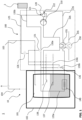
- the fuel cell system 1 shown (at least in sections) in the single figure comprises a fuel cell 2 which is operated with gaseous fuel. This can be stored in a fuel tank 101 of a fuel tank device 10.
- the fuel tank 101 contains gaseous fuel as well as liquid fuel (shown hatched in the fuel tank 101).
- a fuel removal system 100 comprises a conveyor 110 for removing the fuel from the fuel tank 101, which is connected to the interior of the fuel tank 101 via a first line 105.
- the first line 105 preferably begins in an upper region of the fuel tank 101 to direct only gaseous fuel and no liquid fuel from the fuel tank 101.
- the delivery device 110 raises the gaseous fuel from a first pressure level present in the fuel tank 101 to a second pressure level.
- the conveying device 110 can increase the pressure of the gaseous fuel from approximately 2 bar to approximately 20 bar.
- the gaseous fuel is then (intermediately) stored in a buffer tank 120 at the second pressure level.
- the buffer tank 120 has a first outlet 121 to which a second line 125 is connected.
- a portion of the fuel at the second pressure level is conducted via the second line 125 to a pneumatic actuation device 131 of at least one valve 130.
- the second line 125 can comprise a main valve 126, with the second line 125 branching downstream of the main valve 126 and forming supply lines to the respective valve 130a, 130b, 130c.
- additional valves can also have a pneumatic actuating device 131 outside the fuel extraction system, which is actuated via the fuel from the second line 125.
- Each of the actuating devices 131 of the at least one valve 130 can be opened and closed exclusively via the fuel from the second line 125. Alternatively, the opening or closing can also take place independently using a spring element or other mechanical actuator.
- a third line 135 is connected to a second outlet 122 of the buffer tank 120.
- the third line 135 is primarily used to supply the fuel to a consumer, for example a fuel cell 2.
- a first heat exchanger 140 is provided in the third line 135 and is located in a section 135a of the third line 135 through the interior of the fuel tank 101. Through the first heat exchanger 140, thermal energy can be introduced into the liquid fuel in the fuel tank 101, causing it to evaporate.
- a second heat exchanger 150 can be provided in the third line 135, in which the fuel in the third line 135 serves as a heat sink for a coolant of a cooling circuit 155.
- the cooling circuit 155 can be used, for example, to cool the fuel cell 2.
- a third heat exchanger 151 can be provided, which thermally couples the gaseous fuel in the first line 105 with the gaseous fuel in the third line 135. This allows the gaseous fuel in the first line 105 to be kept in the gaseous state or residues of liquid fuel to be evaporated in the third heat exchanger 151.
- the second heat exchanger 150 and the third heat exchanger 151 are shown separately from one another. Of course, it can be a combined heat exchanger that thermally couples the fuel in the first line 105, the fuel in the third line 135 and the coolant of the cooling circuit 155 to one another.
- a bypass line 136 is provided, which bypasses the section 135a of the third line 135 outside the fuel tank 101, and thus bypasses the first heat exchanger 140.
- the bypass line branches off from the third line 135 in front of the section 135a of the third line 135 inside the fuel tank 101 and flows back into the third line 135 after the section 135a.
- a second valve 130b of the at least one valve 130 arranged in the bypass line can regulate a flow rate of the fuel through the bypass line 136, thereby also regulating a flow rate of the fuel through the portion 135a through the interior of the fuel tank 101 and the first heat exchanger 140 becomes.
- a first valve 130a is provided in the third line 135.
- the fuel passed to the first valve 130a is then passed through a further section 135b of the third line 135 to the consumer, for example a fuel cell 2.
- the first valve 130a regulates a flow rate of fuel through the further section 135b of the third line 135.
- the first valve 130a can also be a pressure reducing valve.
- the gaseous fuel can be upstream of the first valve 130a have approximately the second pressure level (with corresponding pressure losses through lines 135, 135a, 136, heat exchangers 140, 150, 151 and / or valves 136), while the first valve 130a supplies the gaseous fuel for the further section 135b of the third Line 135 regulates the pressure level required by the consumer 2.
- the fuel tank device 10 can also provide a protective tank 102 in addition to the fuel tank 101. This serves primarily to collect fuel from the fuel tank 101 that can escape therefrom. Even in the event of an unintentional leak in the fuel tank 101, the protective tank 102 can collect the fuel. Fuel can be safely released from the protective tank 102 into the environment via appropriate safety lines 103, 104.
- the fuel extraction system 100 (except for the fuel tank 101) may be arranged within the protective tank 102.
- fuel that escapes from one of the components shown to the right of the protective tank 102 in the figure can be collected and safely drained.
- the elements of the fuel extraction system 100 in which fuel at the second pressure level is contained, can be arranged in a separate protective container (shown in dashed lines).
- fuel escapes at the second pressure level it can be automatically returned to the fuel tank 101 via a corresponding feed line into the fuel tank 101, for example a feed line 138 for gaseous fuel or a separate feed line, since the fuel is in the fuel tank 101 stored at the first, lower pressure level.
- the buffer tank 122, the third line 135 (with the exception of the section 135a inside the fuel tank 101), the bypass line 136, the second line 125, and the valves 126, 130 can be arranged within the protective container (shown in dashed lines). .
- the fuel tank device 10 may further provide a liquid fuel supply line 137 for filling the fuel tank 101 with liquid fuel.
- a third valve 130c can be arranged in the supply line 137, which also has a pneumatic actuation 131, which is supplied with fuel at the second pressure level via the second line 125 and is actuated.
- the figure also shows a supply line 138 for gaseous fuel. This can also be opened and closed using a corresponding valve (not shown separately).
Landscapes
- Engineering & Computer Science (AREA)
- Mechanical Engineering (AREA)
- General Engineering & Computer Science (AREA)
- Chemical Kinetics & Catalysis (AREA)
- Life Sciences & Earth Sciences (AREA)
- Manufacturing & Machinery (AREA)
- Sustainable Development (AREA)
- Sustainable Energy (AREA)
- Chemical & Material Sciences (AREA)
- Electrochemistry (AREA)
- General Chemical & Material Sciences (AREA)
- Aviation & Aerospace Engineering (AREA)
- Filling Or Discharging Of Gas Storage Vessels (AREA)
- Fuel Cell (AREA)
Description
- Die Erfindung betrifft ein Treibstoffentnahmesystem, eine Treibstofftankvorrichtung sowie ein Brennstoffzellensystem jeweils mit einem Treibstoffentnahmesystem. Insbesondere betrifft die Erfindung ein Treibstoffentnahmesystem sowie eine Treibstofftankvorrichtung und ein Brennstoffzellensystem mit einem Treibstoffentnahmesystem, das gasförmigen Treibstoff aus einem Treibstofftank fördert, auf ein höheres Druckniveau bringt und damit ein Ventil mit einer pneumatischen Betätigungseinrichtung betätigt.
- Herkömmliche Brennstoffzellensysteme sind dazu ausgelegt, gasförmigen und/oder flüssigen Treibstoff, wie zum Beispiel Wasserstoff, über Leitungen zu fördern. Die Leitungen können mit pneumatischen oder elektromagnetischen Ventilen versehen sein, um eine Durchflussmenge des Treibstoffs durch die entsprechende Leitung zu steuern. Für den Betrieb der pneumatischen bzw. elektromagnetischen Ventile ist ein pneumatisches System bzw. ein elektrischer Kreislauf notwendig. In Flugzeugen beispielsweise wurden hierfür entweder bestehende pneumatische Systeme oder elektrische Kreisläufe verwendet und die Betätigungseinrichtung der Ventile daran angeschlossen oder speziell für das Brennstoffzellensystem vorgesehene pneumatische Systeme oder elektrische Kreisläufe installiert. Dadurch erhöht sich jedoch der Leistungsbedarf des jeweiligen Flugzeugssystems sowie das Gewicht für zusätzliche Systeme.
- Aus der
DE 100 21 681 A1 ist beispielsweise ein Energiespeichersystem, insbesondere System zum Speichern von Wasserstoff bekannt. Der Energiespeicher weist einen ersten Speicher auf, der mit einer Zuleitung für einen flüssigen Energieträger, insbesondere für flüssigen Wasserstoff, sowie mit einer Entnahmeleitung zum Transportieren des Energieträgers zu einem Verbraucher versehen ist. - Aus der
WO 2005/003621 A1 ist weiter beispielsweise ein Speichersystem, insbesondere für ein kryogenes Medium bekannt. Dieses weist einen für die Speicherung eines kryogenen Mediums geeigneten Speicherbehälter, eine Zuleitung in den Speicherbehälter, über die dem Speicherbehälter das zu speichernde Medium zugeführt wird, einer Flüssigentnahmeleitung, über die das Medium einem Verbraucher zugeführt wird, und einen in der Flüssigentnahmeleitung angeordneten Kryokompressor, der das dem Verbraucher zuzuführende Medium verdichtet, auf. - Der Erfindung liegt die Aufgabe zugrunde, ein Treibstoffentnahmesystem, eine Treibstofftankvorrichtung sowie ein Brennstoffzellensystem bereitzustellen, die einfacher zu steuern sind und dabei gewichtssparender ausgebildet werden können.
- Diese Aufgabe wird durch ein Treibstoffentnahmesystem mit den Merkmalen des Anspruchs 1, durch eine Treibstofftankvorrichtung mit den Merkmalen des Anspruchs 8 und ein Brennstoffzellensystem mit den Merkmalen des Anspruchs 10 gelöst.
- Gemäß einem ersten Aspekt zum besseren Verständnis der vorliegenden Offenbarung umfasst ein Treibstoffentnahmesystem zum Entnehmen eines gasförmigen Treibstoffs aus einem Treibstofftank eine Fördereinrichtung, die dazu eingerichtet ist, gasförmigen Treibstoff zu fördern und von einem ersten Druckniveau auf ein zweites Druckniveau zu bringen, und eine erste Leitung, die dazu eingerichtet ist, die Fördereinrichtung mit dem Inneren des Treibstofftanks fluidisch zu verbinden.
- Die Fördereinrichtung kann beispielsweise in Form eines Kompressors, eines Gebläses oder einer Pumpe für Gase ausgestaltet sein. Durch die Fördereinrichtung, die das Druckniveau des gasförmigen Treibstoffs erhöhen kann, ist es möglich, den Treibstoff auf einem geringeren Druckniveau in dem Treibstofftank zu lagern, d. h. mit dem ersten Druckniveau. Beispielsweise kann der Treibstoff Wasserstoff für eine Brennstoffzelle sein. Dieser wird üblicherweise bei ca. 6 bis 10 bar gelagert, um mit einem entsprechenden Druckniveau zu der Brennstoffzelle geleitet zu werden, wobei Druckverluste aufgrund von Leitungsführung, Ventilen etc. berücksichtigt werden müssen. Durch die Fördereinrichtung kann der Treibstoff nun bei einem geringeren Druckniveau, beispielsweise 1 bis 4 bar, bevorzugt bei 1 bis 3 bar und besonders bevorzugt bei 2 bar, gelagert werden. Dies erlaubt eine einfachere Struktur des Treibstofftanks, wodurch dieser deutlich leichter und somit gewichtssparender ausgestaltet sein kann. Die Fördereinrichtung kann dazu ausgelegt sein, bei Treibstoff in Form von Wasserstoff diesen von dem ersten Druckniveau in dem Treibstofftank auf das zweite Druckniveau von ca. 15 bis 22 bar, bevorzugt 18 bis 21 bar und besonders bevorzugt 20 bar, anzuheben.
- Ferner umfasst das Treibstoffentnahmesystem einen Puffertank, der dazu eingerichtet ist, den Treibstoff mit dem zweiten Druckniveau zu speichern, und der einen ersten Auslass und einen zweiten Auslass aufweist. Zudem umfasst das Treibstoffentnahmesystem mindestens ein Ventil mit einer pneumatischen Betätigungseinrichtung und eine zweite Leitung, die an den ersten Auslass des Puffertanks angeschlossen ist und dazu eingerichtet ist, einen Teil des Treibstoffs mit dem zweiten Druckniveau zu der pneumatischen Betätigungseinrichtung des mindestens einen Ventils zu leiten. Somit wird/werden Ventil(e) des Treibstoffentnahmesystems mit Treibstoff betrieben, wodurch der Anschluss an ein gesondertes pneumatisches System nicht notwendig ist. Ferner muss ein bereits existierendes pneumatisches System, wie es bei herkömmlichen Treibstoffentnahmesystemen in Flugzeugen der Fall war, nicht für die Betätigung der Ventile des Treibstoffentnahmesystems adaptiert werden. Dadurch lässt sich Gewicht sparen, da Leitungen eines existierenden pneumatischen Systems nicht bis zum Installationsort des Treibstoffentnahmesystems verlängert werden müssen und auch ein druckerzeugendes Gerät in dem pneumatischen System nicht für eine höhere Belastung (maximale Gesamtbelastung) ausgelegt werden muss. Beispielsweise muss ein Kompressor, der in einem Flugzeug betrieben wird, ein sehr hohes Kompressionsverhältnis erzielen, da während der Flugphase ein sehr geringer Umgebungsdruck herrscht und zum Betrieb der Ventile in einem Treibstoffentnahmesystem ein hoher Betätigungsdruck notwendig ist.
- Der Puffertank muss zwar dafür ausgelegt sein, den Treibstoff bei dem höheren zweiten Druckniveau zu speichern. Da der Puffertank jedoch nur für eine Treibstoffmenge ausgelegt sein muss, die zur Betätigung des mindestens einen Ventils und/oder für den Betrieb einer angeschlossenen Brennstoffzelle ausreicht, kann dieser deutlich kleiner als der Treibstofftank dimensioniert sein. Beispielsweise ist es ausreichend, einen Puffertank zur zwischenzeitlichen Lagerung von ca. 10 bis 50 g gasförmigen Treibstoffs, bevorzugt 15 bis 30 g und besonders bevorzugt 20 g gasförmigen Treibstoffs, vorzusehen. Ferner kann die Größe des Puffertanks auch in Abhängigkeit der Leistung einer angeschlossenen Brennstoffzelle ausgelegt sein, beispielsweise zur zwischenzeitlichen Lagerung von ca. 10 bis 50 g pro 100 kW Systemleistung, bevorzugt 15 bis 30 g pro 100 kW und besonders bevorzugt 20 g pro 100 kW. Dadurch wird die Gewichtseinsparung bei dem Treibstofftank, der nicht mehr für hohe Drücke ausgelegt sein muss, kaum bis gar nicht konterkariert. Ferner muss der Puffertank nicht dafür ausgelegt sein, Treibstoff auf dem zweiten Druckniveau für einen längeren Zeitraum zu speichern, beispielsweise während Phasen, in denen das Treibstoffentnahmesystems nicht in Betrieb ist, sondern muss lediglich Treibstoff für die Zeit des Betriebs des Treibstoffentnahmesystems vorhalten. Mit anderen Worten muss der Puffertank nicht so ausgestaltet und gesichert sein, dass er den Treibstoff wie ein üblicher Treibstofftank lange und sicher aufbewahrt. So kann der Puffertank auch entleert werden, wenn das Treibstoffentnahmesystems nicht in Betrieb ist oder abgeschaltet wird. Beispielsweise kann der in dem Puffertank auf dem zweiten Druckniveau gespeicherte Treibstoff aufgrund des höheren Druckniveaus leicht in den Treibstofftank zurückgeführt werden.
- Das Treibstoffentnahmesystem umfasst eine dritte Leitung, die an dem zweiten Auslass des Puffertanks angeschlossen ist und dazu eingerichtet ist, den Treibstoff mit dem zweiten Druckniveau zu einem Verbraucher zu leiten. Der Verbraucher kann ein Motor, eine Brennstoffzelle oder andere Maschine sein, die die Energie des Treibstoffs in elektrische Energie, kinetische Energie und/oder Wärme umsetzt. Wenn der Verbraucher eine Brennstoffzelle ist, benötigt diese Wasserstoff mit einem Druckniveau von ca. 2 bar (2 bar +/- 0,5 bar), welches von der Fördereinrichtung (über den Puffertank) bereitgestellt wird. Somit kann der Treibstoff in dem Treibstofftank bei dem ersten, geringeren Druckniveau gelagert werden, unabhängig von Druckverlusten in Leitungen, Ventilen, etc. zwischen Treibstofftank und Verbraucher.
- Die dritte Leitung weist einen Abschnitt auf, der durch das Innere des Treibstofftanks führt und der einen Wärmetauscher zum Verdampfen von flüssigem Treibstoff in dem Treibstofftank umfasst. Aufgrund der Erhöhung des Drucks des Treibstoffs auf das zweite Druckniveau, wird dem Treibstoff eine bestimmte Menge Energie zugeführt. Beispielsweise wird der gasförmige Treibstoff auch erwärmt, während er durch die Fördereinrichtung komprimiert wird. Somit kann der dem Treibstofftank entnommene und auf das zweite Niveau angehobene Treibstoff als Wärmequelle in dem Treibstofftank verwendet werden, um dort flüssigen Treibstoff zu verdampfen. So kann der Treibstoff in der dritten Leitung einen Sublimierungsenergieeintrag in dem Treibstofftank leisten. Beispielsweise kann bei Wasserstoff als Treibstoff dieser durch die Fördereinrichtung bei Anhebung von dem ersten Druckniveau in dem Treibstofftank auf das zweite Druckniveau in dem Puffertank um ca. 5 K erwärmt. Diese Wärmeenergie reicht für gewöhnlich aus, um flüssigen Wasserstoff in den Treibstofftank zu verdampfen.
- Alternativ oder zusätzlich kann in einer Ausgestaltungsvariante in dem Inneren des Treibstofftanks auch ein gesonderter Wärmetauscher eines gesonderten Kühlkreislaufes angeordnet sein, der Wärmeenergie in den flüssigen Treibstoff abgibt, um dort Sublimierungsenergie einzubringen.
- In einer weiteren Ausgestaltungsvariante kann die pneumatische Betätigungseinrichtung des mindestens einen Ventils dazu eingerichtet sein, das Ventil ausschließlich mittels des Treibstoffs mit dem zweiten Druckniveau zu öffnen und zu schließen. Mit anderen Worten ist der Treibstoff mit dem zweiten Druckniveau in ausreichender Menge und mit ausreichend hohem Druck in dem Pufferspeicher vorhanden, um das mindestens eine Ventil zwischen einer Offenstellung und einer Schliessstellung oder einer dazwischenliegenden teilgeöffneten Stellung zu bewegen. So muss die Betätigungseinrichtung für das mindestens eine Ventil keine zusätzlichen Betätigungselemente, wie zum Beispiel Federn, elektromagnetische Betätiger, etc., umfassen. Eine pneumatische Betätigungseinrichtung des mindestens einen Ventils ist zudem die zuverlässigere Variante, beispielsweise gegenüber elektromagnetisch betriebenen Ventilen. So müssen beispielsweise elektromagnetisch betriebene Ventile einen Motorantrieb o. ä. aufweisen, der bei sehr geringen Temperaturen zuverlässig arbeitet, d. h. schnelle und zuverlässige Schließ- und Öffnungszeiten aufweist.
- In einer anderen Ausgestaltungsvariante kann ein erstes Ventil des mindestens einen Ventils in der dritten Leitung stromabwärts des Abschnitts durch das Innere des Treibstofftanks angeordnet sein und dazu eingerichtet sein, eine Durchflussmenge des Treibstoffs durch die dritte Leitung zu regeln. Mit anderen Worten regelt das erste Ventil die dem Verbraucher zugeführte Treibstoffmenge. Das Treibstoffentnahmesystem benötigt hierfür keine Komponenten eines anderen Systems, beispielsweise eines pneumatischen oder elektrischen Systems. Dadurch kann das Treibstoffentnahmesystems auch sehr kompakt und somit weiter gewichtssparend hergestellt werden. Auch ist ein nachträglicher Einbau oder der Austausch des Treibstoffentnahmesystems aufgrund seiner Kompaktheit schnell und einfach durchzuführen.
- Das erste Ventil kann in einer optionalen Ausgestaltung ein Druckreduzierungsventil sein. Beispielsweise kann das erste Ventil den gasförmigen Treibstoff stromaufwärts des ersten Ventils auf dem zweiten Druckniveau halten, während stromabwärts des ersten Ventils in der dritten Leitung ein drittes Druckniveau eingestellt wird. Beispielsweise kann das erste Ventil den Druck des gasförmigen Treibstoffs auf ca. 8 bis 12 bar, bevorzugt 9 bis 11 bar und besonders bevorzugt 10 bar, reduzieren. Dies entspricht einem üblichen Druck des Treibstoffs in Brennstoffzellensystemen. Der gasförmige Treibstoff in den Leitungen des Treibstoffentnahmesystems, insbesondere der zweiten und dritten Leitung, kann somit auf dem zweiten Druckniveau gehalten werden, wodurch eine Verflüssigung des Treibstoffs verhindert wird. Auch wenn das Treibstoffentnahmesystem zwischenzeitlich außer Betrieb ist, kann der Treibstoff in den Leitungen auf dem zweiten Druckniveau gehalten werden und somit vor einer Verflüssigung geschützt werden, wodurch stromabwärts gelegene Bauteile, wie zum Beispiel Leitungen, Ventile, etc., nicht durch flüssigen Treibstoff beschädigt werden.
- In einer anderen Ausgestaltungsvariante kann das Treibstoffentnahmesystem ferner eine Bypass-Leitung, die den Abschnitt der dritten Leitung durch das Innere des Treibstofftanks außerhalb des Treibstofftanks umgeht, und ein zweites Ventil des mindestens einen Ventils, das in der Bypass-Leitung angeordnet ist und dazu eingerichtet ist, eine Durchflussmenge des Treibstoffs durch die Bypass-Leitung zu regeln, umfassen. Durch die Bypass-Leitung kann der Wärmeeintrag in den Treibstofftank gesteuert werden. So kann durch Öffnen des zweiten Ventils Treibstoff auf dem zweiten Druckniveau an dem Treibstofftank vorbeigeführt werden, sodass weniger Energie (Wärmeenergie) über den ersten Wärmetauscher in dem Abschnitt der dritten Leitung durch das Innere des Treibstofftanks in den (flüssigen) Treibstoff eingebracht wird. Die Steuerung der Durchflussmenge durch die Bypass-Leitung erfolgt ebenfalls über ein Ventil, welches eine pneumatische Betätigung aufweist, die wiederum mit dem Treibstoff auf dem zweiten Druckniveau aus der zweiten Leitung betrieben wird. Somit sind für die Bypass-Leitung und deren Betrieb keine zusätzlichen Systeme zum Ansteuern des zweiten Ventils (Bypass-Ventils) notwendig.
- In noch einer weiteren Ausgestaltungsvariante kann das Treibstoffentnahmesystem einen zweiten Wärmetauscher umfassen, der dazu eingerichtet ist, den gasförmigen Treibstoff als Wärmesenke für ein Kühlmittel eines Kühlkreislaufes zu nutzen. Der zweite Wärmetauscher kann beispielsweise in der ersten Leitung, zweiten Leitung und/oder dritten Leitung angeordnet sein. Der Treibstoff, insbesondere im Fall von Wasserstoff, weist für gewöhnlich ein sehr geringes Temperaturniveau auf, wodurch er sich sehr gut eignet, um als Wärmesenke eines Kühlsystems zu dienen. Zudem wird über den Wärmeenergieeintrag in den Treibstoff eine Verflüssigung des Treibstoffs in der entsprechenden Leitung verhindert und/oder das Druckniveau weiter erhöht, wodurch keine zusätzlichen Fördereinrichtungen bis zum Verbraucher notwendig sind. Beispielsweise kann der zweite Wärmetauscher in der dritten Leitung zwischen dem zweiten Auslass des Puffertanks und dem Abschnitt der dritten Leitung durch das Innere des Treibstofftanks angeordnet sein. Somit kann die über den zweiten Wärmetauscher aufgenommene Wärmeenergie über den ersten Wärmetauscher an den (flüssigen) Treibstoff in den Treibstofftank abgegeben werden. Alternativ oder zusätzlich kann der erste Wärmetauscher auch in der ersten Leitung angeordnet sein. Dadurch wird der gasförmige Treibstoff in der ersten Leitung erwärmt und sein Druckniveau bereits angehoben, wodurch die Fördereinrichtung weniger Arbeit zum Anheben des Drucks des Treibstoffs auf das zweite Druckniveau benötigt.
- Bei dem Kühlkreislauf kann es sich beispielsweise um einen Kühlkreislauf eines Brennstoffzellensystems handeln, wobei das Treibstoffentnahmesystem Teil des Brennstoffzellensystems ist. Mit anderen Worten wird die in der Brennstoffzelle des Brennstoffzellensystems erzeugte Abwärme zum Betrieb des Treibstoffentnahmesystems verwendet. Das Kühlmittel in dem Kühlkreislauf eines Brennstoffzellensystems kann eine Temperatur von ca. 60 bis 90 °C aufweisen, während gelagerter Wasserstoff als Treibstoff eine Temperatur von ca. -240 bis -250 °C (ca. 20 bis 30 K) hat und somit eine sehr gute Wärmesenke darstellt.
- Alternativ oder zusätzlich kann das Treibstoffentnahmesystem ferner einen dritten Wärmetauscher umfassen, der dazu eingerichtet ist, den gasförmigen Treibstoff in der ersten Leitung mit dem gasförmigen Treibstoff in der dritten Leitung thermisch zu koppeln. Dabei kann der gasförmige Treibstoff in der ersten Leitung im Temperaturniveau angehoben werden, da der gasförmige Treibstoff in der dritten Leitung aufgrund der Anhebung auf das zweite Druckniveau durch die Fördereinrichtung auch eine höhere Temperatur als der Treibstoff in der ersten Leitung aufweist. Dies verhindert eine Verflüssigung des Treibstoffs in der ersten Leitung oder ermöglicht eine Verdampfung von Resten flüssigen Treibstoffs in der ersten Leitung, bevor dieser der Fördereinrichtung zugeführt wird. Dadurch lassen sich Schäden an der Fördereinrichtung durch flüssigen Treibstoff verhindern. Gemäß einer Variante ist der erste Wärmetauscher und der dritten Wärmetauscher in einem gemeinsamen Bauteil kombiniert, sodass der Treibstoff in der ersten Leitung, der Treibstoff in der dritten Leitung und das Kühlmittel in dem Kühlkreislauf untereinander thermisch gekoppelt sind.
- In einer weiteren Ausgestaltungsvariante kann das Treibstoffentnahmesystem ein Hauptventil umfassen, das in der zweiten Leitung angeordnet ist und das dazu eingerichtet ist, eine Durchflussmenge des Treibstoffs mit dem zweiten Druckniveau durch die zweite Leitung zu regeln. Das Hauptventil regelt somit den Zufluss von Treibstoff auf dem zweiten Druckniveau zu der pneumatischen Betätigung des mindestens einen Ventils. Durch Schließen des Hauptventils kann der Betrieb des Treibstoffentnahmesystems eingestellt werden. Beispielsweise kann jedes des mindestens einen Ventils so ausgestaltet sein, dass es sich in einer Ruhestellung immer im geschlossenen Zustand befindet (beispielsweise mittels einer mechanischen Feder oder dergleichen). Die pneumatische Betätigung dient dann dem Öffnen des Ventils bis zu dem gewünschten Öffnungsgrad. Selbstverständlich kann jedes des mindestens einen Ventils auch so ausgestaltet sein, dass der Treibstoff auf dem zweiten Druckniveau zur pneumatischen Betätigung sowohl zum Öffnen als auch Schließen des Ventils verwendet wird.
- Gemäß einem weiteren Aspekt zum besseren Verständnis der vorliegenden Offenbarung umfasst eine Treibstofftankvorrichtung einen Treibstofftank zum Speichern eines Treibstoffs in flüssigem und/oder gasförmigem Zustand und ein Treibstoffentnahmesystem gemäß dem ersten Aspekt. Dabei kann die erste Leitung beispielsweise in einem (im eingebauten Zustand des Treibstofftanks) oberen Abschnitt des Treibstofftanks eine Öffnung aufweisen, um gasförmigen Treibstoff durch die erste Leitung zu der Fördereinrichtung zu leiten. Der erste Wärmetauscher, der im Inneren des Treibstofftanks angeordnet ist, kann wiederum in einem (im eingebauten Zustand des Treibstofftanks) unteren Abschnitt des Treibstofftanks vorgesehen sein, beispielsweise in einem Sumpf des Treibstofftanks, um von flüssigem Treibstoff umgeben zu sein.
- In einer Ausgestaltungsvariante kann die Treibstofftankvorrichtung ferner eine Zuleitung in den Treibstofftank zum Befüllen des Treibstofftanks mit flüssigem Treibstoff und ein drittes Ventil des mindestens einen Ventils, das in der Zuleitung angeordnet ist und dazu eingerichtet ist, eine Durchflussmenge des Treibstoffs durch die Zuleitung zu regeln, umfassen. Dadurch kann die Treibstofftankvorrichtung auch während des Betriebs mit flüssigem Treibstoff gefüllt werden. Zur Steuerung des flüssigen Treibstoffs, der in den Treibstofftank geleitet wird, wird kein zusätzliches System benötigt. Lediglich die Fördereinrichtung des Treibstoffentnahmesystems muss betrieben werden, um das dritte Ventil pneumatisch zu betätigen.
- Gemäß einem weiteren Aspekt zum besseren Verständnis der vorliegenden Offenbarung umfasst ein Brennstoffzellensystem eine Brennstoffzelle, die mit gasförmigem Treibstoff betrieben ist, und ein Treibstoffentnahmesystem gemäß dem ersten Aspekt. Alternativ oder zusätzlich kann das Brennstoffzellensystem eine Treibstofftankvorrichtung gemäß dem weiteren (zweiten) Aspekt umfassen.
- Gemäß noch einem weiteren Aspekt zum besseren Verständnis der vorliegenden Offenbarung umfasst ein Flugzeug ein Treibstoffentnahmesystem, eine Treibstofftankvorrichtung und/oder ein Brennstoffzellensystem gemäß der vorherigen Aspekte. Der Umfang der vorliegenden Erfindung ist lediglich durch die beiliegenden Patentansprüche definiert.
- Die oben beschriebenen Aspekte, Ausgestaltungen und Varianten können selbstverständlich kombiniert werden, ohne dass dies explizit beschrieben ist. Jede der beschriebenen Ausgestaltungsvarianten ist somit optional zu jedem der Aspekte, Ausgestaltungen und Varianten oder bereits Kombinationen davon zu sehen. Die vorliegende Offenbarung ist somit nicht auf die einzelnen Ausgestaltungen und Ausgestaltungsvarianten in der beschriebenen Reihenfolge oder einer bestimmten Kombination der Aspekte und Ausgestaltungsvarianten beschränkt.
- Eine bevorzugte Ausführungsform der Erfindung wird nun anhand der beigefügten schematischen Zeichnung näher erläutert, die ein Treibstoffentnahmesystem, eine Treibstofftankvorrichtung sowie einen Teil eines Brennstoffzellensystems zeigt.
- Das in der einzigen Figur (zumindest abschnittsweise) dargestellte Brennstoffzellensystem 1 umfasst eine Brennstoffzelle 2, die mit gasförmigem Treibstoff betrieben wird. Dieser kann in einem Treibstofftank 101 einer Treibstofftankvorrichtung 10 gelagert werden. Der Treibstofftank 101 enthält gasförmigen Treibstoff sowie flüssigen Treibstoff (in dem Treibstofftank 101 schraffiert dargestellt).
- Ein Treibstoffentnahmesystem 100 umfasst zur Entnahme des Treibstoffs aus dem Treibstofftank 101 eine Fördereinrichtung 110, die über eine erste Leitung 105 mit dem Inneren des Treibstofftanks 101 verbunden ist. Die erste Leitung 105 beginnt vorzugsweise in einem oberen Bereich des Treibstofftanks 101, um nur gasförmigen Treibstoff und keinen flüssigen Treibstoff aus dem Treibstofftank 101 zu leiten. Die Fördereinrichtung 110 hebt den gasförmigen Treibstoff von einem ersten Druckniveau, das in dem Treibstofftank 101 vorliegt, auf ein zweites Druckniveau an. Beispielsweise kann die Fördereinrichtung 110 den Druck des gasförmigen Treibstoffs von ca. 2 bar auf ca. 20 bar anheben.
- Anschließend wird der gasförmige Treibstoff mit dem zweiten Druckniveau in einem Puffertank 120 (zwischen-) gespeichert. Der Puffertank 120 weist einen ersten Auslass 121 auf, an dem eine zweite Leitung 125 angeschlossen ist. Über die zweite Leitung 125 wird ein Teil des Treibstoffs mit dem zweiten Druckniveau zu einer pneumatischen Betätigungseinrichtung 131 mindestens eines Ventils 130 geleitet. Hierfür kann die zweite Leitung 125 ein Hauptventil 126 umfassen, wobei sich die zweite Leitung 125 stromabwärts des Hauptventils 126 verzweigt und Zuleitungen zu dem jeweiligen Ventil 130a, 130b, 130c bildet. Selbstverständlich können weitere Ventile auch außerhalb des Treibstoffentnahmesystems über eine pneumatischen Betätigungseinrichtung 131 verfügen, die über den Treibstoff aus der zweiten Leitung 125 betätigt wird. Jede der Betätigungseinrichtungen 131 des mindestens einen Ventils 130 kann ausschließlich über den Treibstoff aus der zweiten Leitung 125 geöffnet und geschlossen werden. Alternativ kann das Öffnen oder Schließen auch über ein Federelement oder anderen mechanischen Betätiger selbständig erfolgen.
- An einem zweiten Auslass 122 des Puffertanks 120 ist eine dritte Leitung 135 angeschlossen. Die dritte Leitung 135 dient in erster Linie der Zuführung des Treibstoffs zu einem Verbraucher, beispielsweise einer Brennstoffzelle 2.
- In der dritten Leitung 135 ist ein erster Wärmetauscher 140 vorgesehen, der sich in einem Abschnitt 135a der dritten Leitung 135 durch das Innere des Treibstofftanks 101 befindet. Durch den ersten Wärmetauscher 140 kann Wärmeenergie in den flüssigen Treibstoff in dem Treibstofftank 101 eingebracht werden, wodurch dieser verdampft.
- Ferner kann in der dritten Leitung 135 ein zweiter Wärmetauscher 150 vorgesehen sein, in dem der Treibstoff in der dritten Leitung 135 als Wärmesenke für ein Kühlmittel eines Kühlkreislaufes 155 dient. Der Kühlkreislauf 155 kann beispielsweise zur Kühlung der Brennstoffzelle 2 verwendet werden. Alternativ oder zusätzlich kann ein dritter Wärmetauscher 151 vorgesehen sein, der den gasförmigen Treibstoff in der ersten Leitung 105 mit dem gasförmigen Treibstoff in der dritten Leitung 135 thermisch gekoppelt. Dadurch lässt sich der gasförmige Treibstoff in der ersten Leitung 105 im gasförmigen Zustand halten oder Reste von flüssigem Treibstoff in dem dritten Wärmetauscher 151 verdampft werden. In der Figur sind der zweite Wärmetauscher 150 und der dritte Wärmetauscher 151 getrennt voneinander dargestellt. Selbstverständlich kann es sich um einen kombinierten Wärmetauscher handeln, der den Treibstoff in der ersten Leitung 105, den Treibstoff in der dritten Leitung 135 und das Kühlmittel des Kühlkreislaufes 155 thermisch miteinander koppelt.
- Um die Menge des zu verdampfenden Treibstoffs in dem Treibstofftank 101 durch den ersten Wärmetauscher 140 zu regeln, ist eine Bypass-Leitung 136 vorgesehen, die den Abschnitt 135a der dritten Leitung 135 außerhalb des Treibstofftanks 101 umgeht, und somit den ersten Wärmetauscher 140 umgeht. Die Bypass-Leitung zweigt vor dem Abschnitt 135a der dritten Leitung 135 im Inneren des Treibstofftanks 101 von der dritten Leitung 135 ab und mündet nach dem Abschnitt 135a wieder in die dritte Leitung 135 ein. Ein in der Bypass-Leitung angeordnetes zweites Ventil 130b des mindestens einen Ventils 130 kann eine Durchflussmenge des Treibstoffs durch die Bypass-Leitung 136 regeln, wodurch auch eine Durchflussmenge des Treibstoffs durch den Abschnitt 135a durch das Innere des Treibstofftanks 101 und den ersten Wärmetauscher 140 geregelt wird.
- Nach dem Abschnitt 135a und/oder der Bypass-Leitung 136 ist in der dritten Leitung 135 ein erstes Ventil 130a vorgesehen. Der bis zu dem ersten Ventil 130a geleitete Treibstoff wird anschließend durch einen weiteren Abschnitt 135b der dritten Leitung 135 zu dem Verbraucher, beispielsweise einer Brennstoffzelle 2, geleitet. Hierfür regelt das erste Ventil 130a eine Durchflussmenge des Treibstoffs durch den weiteren Abschnitt 135b der dritten Leitung 135. Das erste Ventil 130a kann auch ein Druckminderungsventil sein. Beispielsweise kann der gasförmige Treibstoff stromaufwärts des ersten Ventils 130a in etwa das zweite Druckniveau aufweisen (mit entsprechenden Druckverlusten durch Leitungen 135, 135a, 136, Wärmetauscher 140, 150, 151 und/oder Ventile 136), während das erste Ventil 130a den gasförmigen Treibstoff für den weiteren Abschnitt 135b der dritten Leitung 135 auf das von dem Verbraucher 2 benötigte Druckniveau regelt.
- Die Treibstofftankvorrichtung 10 kann neben dem Treibstofftank 101 auch einen Schutztank 102 vorsehen. Dieser dient in erster Linie dem Auffangen von Treibstoff aus dem Treibstofftank 101, der daraus entweichen kann. Auch im Fall einer ungewollten Leckage des Treibstofftanks 101 kann der Schutztank 102 den Treibstoff auffangen. Über entsprechende Sicherheitsleitungen 103, 104 kann Treibstoff aus dem Schutztank 102 sicher in die Umgebung abgegeben werden.
- Ferner kann das Treibstoffentnahmesystem 100 (mit Ausnahme des Treibstofftanks 101) innerhalb des Schutztanks 102 angeordnet sein. Dadurch kann Treibstoff, der aus einem der in der Figur rechts neben dem Schutztank 102 dargestellten Bauteile entweicht, aufgefangen und sicher abgelassen werden. Alternativ können die Elemente des Treibstoffentnahmesystems 100, in denen Treibstoff mit dem zweiten Druckniveau enthalten ist, in einem gesonderten Schutzbehälter (gestrichelt dargestellt) angeordnet sein. Für den Fall, dass Treibstoff mit dem zweiten Druckniveau entweicht, kann dieser über eine entsprechende Zuleitung in den Treibstofftank 101, beispielsweise eine Zuleitung 138 für gasförmigen Treibstoff oder eine gesonderte Zuleitung, selbsttätig in den Treibstofftank 101 zurückgeführt werden, da der Treibstoff in den Treibstofftank 101 auf dem ersten, niedrigeren Druckniveau lagert. Nur beispielhaft können der Puffertank 122, die dritte Leitung 135 (mit Ausnahme des Abschnitts 135a im Inneren des Treibstofftanks 101), die Bypass-Leitung 136, die zweite Leitung 125, und die Ventile 126, 130 innerhalb des Schutzbehälters (gestrichelt dargestellt) angeordnet sein.
- Die Treibstofftankvorrichtung 10 kann ferner eine Zuleitung 137 für flüssigen Treibstoff zum Befüllen des Treibstofftanks 101 mit flüssigem Treibstoff vorsehen. In der Zuleitung 137 kann ein drittes Ventil 130c angeordnet sein, das ebenfalls über eine pneumatische Betätigung 131 verfügt, welche über die zweite Leitung 125 mit Treibstoff auf dem zweiten Druckniveau versorgt und betätigt wird. In der Figur ist zusätzlich eine Zuleitung 138 für gasförmigen Treibstoff dargestellt. Diese kann ebenfalls über ein entsprechendes Ventil (nicht gesondert dargestellt) geöffnet und geschlossen werden.
Claims (10)
- Treibstoffentnahmesystem (100) zum Entnehmen eines gasförmigen Treibstoffs aus einem Treibstofftank (101), umfassend:- eine Fördereinrichtung (110), die dazu eingerichtet ist, gasförmigen Treibstoff zu fördern und von einem ersten Druckniveau auf ein zweites Druckniveau zu bringen;- eine erste Leitung (105), die dazu eingerichtet ist, die Fördereinrichtung (110) mit dem Inneren des Treibstofftanks (101) fluidisch zu verbinden;- einen Puffertank (120), der dazu eingerichtet ist, den Treibstoff mit dem zweiten Druckniveau zu speichern, und der einen ersten Auslass (121) und einen zweiten Auslass (122) aufweist;- mindestens ein Ventil (130) mit einer pneumatischen Betätigungseinrichtung (131); und- eine zweite Leitung (125), die an den ersten Auslass (121) des Puffertanks (120) angeschlossen ist; und- eine dritte Leitung (135), die dazu eingerichtet ist, den Treibstoff mit dem zweiten Druckniveau zu einem Verbraucher (2) zu leiten,dadurch gekennzeichnet, dassdie zweite Leitung (125) dazu eingerichtet ist, einen Teil des Treibstoffs mit dem zweiten Druckniveau zu der pneumatischen Betätigungseinrichtung (131) des mindestens einen Ventils (130) zu leiten,die dritte Leitung (135) an dem zweiten Auslass (122) des Puffertanks (120) angeschlossen ist, unddie dritte Leitung (135) einen Abschnitt (135a) aufweist, der durch das Innere des Treibstofftanks (101) führt und der einen ersten Wärmetauscher (140) zum Verdampfen von flüssigem Treibstoff in dem Treibstofftank (101) umfasst.
- Treibstoffentnahmesystem (100) gemäß Anspruch 1, wobei die pneumatische Betätigungseinrichtung (131) des mindestens einen Ventils (130) dazu eingerichtet ist, das Ventil (130) ausschließlich mittels des Treibstoffs mit dem zweiten Druckniveau zu öffnen und zu schließen.
- Treibstoffentnahmesystem (100) gemäß Anspruch 1 oder 2, wobei ein erstes Ventil (130a) des mindestens einen Ventils (130) in der dritten Leitung (135) stromabwärts des Abschnitts (135a) durch das Innere des Treibstofftanks (101) angeordnet ist und dazu eingerichtet ist, eine Durchflussmenge des Treibstoffs durch die dritte Leitung (135) zu regeln.
- Treibstoffentnahmesystem (100) gemäß Anspruch 1 oder 3, ferner umfassend:- eine Bypass-Leitung (136), die den Abschnitt (135a) der dritten Leitung (135) durch das Innere des Treibstofftanks (101) außerhalb des Treibstofftanks (101) umgeht; und- ein zweites Ventil (130b) des mindestens einen Ventils (130), das in der Bypass-Leitung (136) angeordnet ist und dazu eingerichtet ist, eine Durchflussmenge des Treibstoffs durch die Bypass-Leitung (136) zu regeln.
- Treibstoffentnahmesystem (100) gemäß einem der Ansprüche 1 bis 4, ferner umfassend:- einen zweiten Wärmetauscher (150), der dazu eingerichtet ist, den gasförmigen Treibstoff als Wärmesenke für ein Kühlmittel eines Kühlkreislaufes (155) zu nutzen.
- Treibstoffentnahmesystem (100) gemäß einem der Ansprüche 1 bis 5, ferner umfassend:- einen dritten Wärmetauscher (151), der dazu eingerichtet ist, den gasförmigen Treibstoff in der ersten Leitung (105) mit dem gasförmigen Treibstoff in der dritten Leitung (135) thermisch zu koppeln.
- Treibstoffentnahmesystem (100) gemäß einem der Ansprüche 1 bis 6, ferner umfassend:- ein Hauptventil (126), das in der zweiten Leitung (125) angeordnet ist und das dazu eingerichtet ist, eine Durchflussmenge des Treibstoffs mit dem zweiten Druckniveau durch die zweite Leitung (125) zu regeln.
- Treibstofftankvorrichtung (10), umfassend:- einen Treibstofftank (101) zum Speichern eines Treibstoffs in flüssigem und gasförmigem Zustand; und- ein Treibstoffentnahmesystem (100) gemäß einem der Ansprüche 1 bis 7.
- Treibstofftankvorrichtung (10) gemäß Anspruch 8, ferner umfassend:- eine Zuleitung (137) in den Treibstofftank (101) zum Befüllen des Treibstofftanks (101) mit flüssigem Treibstoff; und- ein drittes Ventil (130c) des mindestens einen Ventils (130), das in der Zuleitung (137) angeordnet ist und dazu eingerichtet ist, eine Durchflussmenge des Treibstoffs durch die Zuleitung (137) zu regeln.
- Brennstoffzellensystem (1), umfassend:- eine Brennstoffzelle (2), die mit gasförmigem Treibstoff betrieben ist; und- ein Treibstoffentnahmesystem (100) gemäß einem der Ansprüche 1 bis 7; oder- eine Treibstofftankvorrichtung (10) gemäß Anspruch 8 oder 9.
Applications Claiming Priority (1)
| Application Number | Priority Date | Filing Date | Title |
|---|---|---|---|
| DE102019108158.0A DE102019108158A1 (de) | 2019-03-29 | 2019-03-29 | Treibstoffentnahmesystem, Treibstofftankvorrichtung mit Treibstoffentnahmesystem und Brennstoffzellensystem mit Treibstoffentnahmesystem |
Publications (2)
| Publication Number | Publication Date |
|---|---|
| EP3715261A1 EP3715261A1 (de) | 2020-09-30 |
| EP3715261B1 true EP3715261B1 (de) | 2023-09-27 |
Family
ID=70008446
Family Applications (1)
| Application Number | Title | Priority Date | Filing Date |
|---|---|---|---|
| EP20165808.5A Active EP3715261B1 (de) | 2019-03-29 | 2020-03-26 | Treibstoffentnahmesystem, treibstofftankvorrichtung mit treibstoffentnahmesystem und brennstoffzellensystem mit treibstoffentnahmesystem |
Country Status (4)
| Country | Link |
|---|---|
| US (1) | US11434019B2 (de) |
| EP (1) | EP3715261B1 (de) |
| CN (1) | CN111755716A (de) |
| DE (1) | DE102019108158A1 (de) |
Families Citing this family (6)
| Publication number | Priority date | Publication date | Assignee | Title |
|---|---|---|---|---|
| EP3961083B1 (de) * | 2020-08-31 | 2024-08-21 | Salzburger Aluminium Aktiengesellschaft | Tanksystem |
| CN112644721B (zh) * | 2020-12-23 | 2022-06-03 | 河北利翔航空科技有限公司 | 一种飞机供输油系统及其控制方法 |
| IT202100020324A1 (it) * | 2021-07-29 | 2023-01-29 | Ierom S R L | Sistema di compenso per serbatoio criogenico per il contenimento di idrogeno liquido |
| EP4191119B1 (de) * | 2021-12-06 | 2025-08-27 | Airbus (S.A.S.) | Wasserstofftankanordnung für ein fahrzeug wie z.b. ein flugzeug |
| FR3130928B1 (fr) * | 2021-12-22 | 2024-07-05 | Faurecia Systemes Dechappement | Dispositif de stockage et d’alimentation en hydrogène et ensemble correspondant |
| EP4279795B1 (de) * | 2022-05-17 | 2026-04-22 | Zero Emissions Aerospace Limited | Brennstoffzuführsystem |
Family Cites Families (10)
| Publication number | Priority date | Publication date | Assignee | Title |
|---|---|---|---|---|
| US5183074A (en) * | 1991-09-30 | 1993-02-02 | Cla-Val Co. | Pressure-reducing valve, and aircraft fueling system incorporating the same |
| DE19910893A1 (de) * | 1999-03-11 | 2000-09-14 | Linde Ag | Tanksystem für kryogene Kraftstoffe |
| DE10021681C2 (de) * | 2000-05-05 | 2002-06-13 | Messer Griesheim Gmbh | Energiespeichersystem, insbesondere System zum Speichern von Wasserstoff |
| JP3588776B2 (ja) * | 2001-11-09 | 2004-11-17 | 本田技研工業株式会社 | 燃料循環式燃料電池システム |
| JP3659582B2 (ja) * | 2001-11-20 | 2005-06-15 | 本田技研工業株式会社 | 燃料循環式燃料電池システム |
| DE10330308A1 (de) | 2003-07-04 | 2005-02-03 | Linde Ag | Speichersystem für kryogene Medien |
| JP4877711B2 (ja) * | 2005-08-04 | 2012-02-15 | 本田技研工業株式会社 | 燃料電池システム |
| US7976990B2 (en) * | 2005-12-06 | 2011-07-12 | Honda Motor Co., Ltd. | High efficiency fuel cell system |
| CN101978541B (zh) * | 2008-03-18 | 2015-08-19 | 戴姆勒股份公司 | 燃料电池系统 |
| JP4864072B2 (ja) * | 2008-12-05 | 2012-01-25 | 本田技研工業株式会社 | 燃料電池システム |
-
2019
- 2019-03-29 DE DE102019108158.0A patent/DE102019108158A1/de not_active Withdrawn
-
2020
- 2020-03-19 CN CN202010198598.5A patent/CN111755716A/zh active Pending
- 2020-03-23 US US16/826,977 patent/US11434019B2/en active Active
- 2020-03-26 EP EP20165808.5A patent/EP3715261B1/de active Active
Also Published As
| Publication number | Publication date |
|---|---|
| US11434019B2 (en) | 2022-09-06 |
| CN111755716A (zh) | 2020-10-09 |
| US20200309324A1 (en) | 2020-10-01 |
| DE102019108158A1 (de) | 2020-10-01 |
| EP3715261A1 (de) | 2020-09-30 |
Similar Documents
| Publication | Publication Date | Title |
|---|---|---|
| EP3715261A1 (de) | Treibstoffentnahmesystem, treibstofftankvorrichtung mit treibstoffentnahmesystem und brennstoffzellensystem mit treibstoffentnahmesystem | |
| EP2831491B1 (de) | Betriebsverfahren für einen kryo-drucktank | |
| EP2831492B1 (de) | Betriebsverfahren für eine brennstoffzellen-anlage | |
| EP3269002B1 (de) | Kühlanordnung zum kühlen einer brennstoffzelle | |
| EP3017238B1 (de) | Vorrichtung zum kühlen eines verbrauchers mit einer unterkühlten flüssigkeit in einem kühlkreislauf | |
| EP2574740A1 (de) | Anlage zur Speicherung thermischer Energie | |
| EP3236132B1 (de) | Tanksystem | |
| EP2992194A1 (de) | Kühlkreislauf | |
| DE102016008059A1 (de) | Tankventil | |
| WO2002027153A1 (de) | Verfahren und vorrichtung zum warmziehen und entwässern von an dampfturbinenstufen angeschlossenen dampfzuleitungen | |
| DE102020106625A1 (de) | Nachheizverfahren zum Betreiben einer Kälteanlage für ein Kraftfahrzeug, Kälteanlage und Kraftfahrzeug mit einer solchen Kälteanlage | |
| DE102008063563A1 (de) | Kraftstoffversorgungssystem mit einem Tieftemperaturtank | |
| EP3236133B1 (de) | Tanksystem | |
| DE102018005807A1 (de) | Verflüssigung eines gasförmigen Mediums | |
| DE102005007551B4 (de) | Verfahren zum Betreiben eines Tieftemperatur-Flüssiggasspeichertanks | |
| DE102011114728A1 (de) | Vorrichtung zur Speicherung eines gasförmigen Brennstoffs | |
| EP0736214B1 (de) | Sicherheitseinspeise- und boriersystem für einen druckwasserreaktor und verfahren zum betrieb eines solchen systems | |
| WO2016041710A1 (de) | Druckminderungseinrichtung für eine vorrichtung zur kraftstoffversorgung und vorrichtung zur kraftstoffversorgung | |
| EP3816413A1 (de) | Druckregelung für geschlossene joule-kreisprozesse | |
| DE102017217348A1 (de) | Druckbehältersystem und Verfahren zum Zuführen von Brennstoff aus einem Druckbehältersystem | |
| DE3511421A1 (de) | Kaeltemittelkreislauf fuer eine kaelteanlage | |
| DE2352147C3 (de) | Vorrichtung zur Versorgung eines Kryostaten | |
| DE102024114886A1 (de) | Tanksystem und Verfahren zur Versorgung eines Verbrauchers | |
| DE102023112791A1 (de) | Wärmepumpenanlage zum Heizen und/oder Kühlen von Gebäuden oder Gebäudeteilen | |
| EP4031761B1 (de) | Kaltstart-system für ein mit verdichtetem gas betriebenes fahrzeug mit einer monovalenten kraftstoffversorgung |
Legal Events
| Date | Code | Title | Description |
|---|---|---|---|
| PUAI | Public reference made under article 153(3) epc to a published international application that has entered the european phase |
Free format text: ORIGINAL CODE: 0009012 |
|
| STAA | Information on the status of an ep patent application or granted ep patent |
Free format text: STATUS: THE APPLICATION HAS BEEN PUBLISHED |
|
| AK | Designated contracting states |
Kind code of ref document: A1 Designated state(s): AL AT BE BG CH CY CZ DE DK EE ES FI FR GB GR HR HU IE IS IT LI LT LU LV MC MK MT NL NO PL PT RO RS SE SI SK SM TR |
|
| AX | Request for extension of the european patent |
Extension state: BA ME |
|
| STAA | Information on the status of an ep patent application or granted ep patent |
Free format text: STATUS: REQUEST FOR EXAMINATION WAS MADE |
|
| 17P | Request for examination filed |
Effective date: 20210330 |
|
| RBV | Designated contracting states (corrected) |
Designated state(s): AL AT BE BG CH CY CZ DE DK EE ES FI FR GB GR HR HU IE IS IT LI LT LU LV MC MK MT NL NO PL PT RO RS SE SI SK SM TR |
|
| STAA | Information on the status of an ep patent application or granted ep patent |
Free format text: STATUS: EXAMINATION IS IN PROGRESS |
|
| 17Q | First examination report despatched |
Effective date: 20220502 |
|
| GRAP | Despatch of communication of intention to grant a patent |
Free format text: ORIGINAL CODE: EPIDOSNIGR1 |
|
| STAA | Information on the status of an ep patent application or granted ep patent |
Free format text: STATUS: GRANT OF PATENT IS INTENDED |
|
| INTG | Intention to grant announced |
Effective date: 20230706 |
|
| GRAS | Grant fee paid |
Free format text: ORIGINAL CODE: EPIDOSNIGR3 |
|
| GRAA | (expected) grant |
Free format text: ORIGINAL CODE: 0009210 |
|
| STAA | Information on the status of an ep patent application or granted ep patent |
Free format text: STATUS: THE PATENT HAS BEEN GRANTED |
|
| AK | Designated contracting states |
Kind code of ref document: B1 Designated state(s): AL AT BE BG CH CY CZ DE DK EE ES FI FR GB GR HR HU IE IS IT LI LT LU LV MC MK MT NL NO PL PT RO RS SE SI SK SM TR |
|
| REG | Reference to a national code |
Ref country code: GB Ref legal event code: FG4D Free format text: NOT ENGLISH |
|
| REG | Reference to a national code |
Ref country code: CH Ref legal event code: EP |
|
| REG | Reference to a national code |
Ref country code: DE Ref legal event code: R096 Ref document number: 502020005354 Country of ref document: DE |
|
| REG | Reference to a national code |
Ref country code: IE Ref legal event code: FG4D Free format text: LANGUAGE OF EP DOCUMENT: GERMAN |
|
| REG | Reference to a national code |
Ref country code: LT Ref legal event code: MG9D |
|
| PG25 | Lapsed in a contracting state [announced via postgrant information from national office to epo] |
Ref country code: GR Free format text: LAPSE BECAUSE OF FAILURE TO SUBMIT A TRANSLATION OF THE DESCRIPTION OR TO PAY THE FEE WITHIN THE PRESCRIBED TIME-LIMIT Effective date: 20231228 |
|
| PG25 | Lapsed in a contracting state [announced via postgrant information from national office to epo] |
Ref country code: SE Free format text: LAPSE BECAUSE OF FAILURE TO SUBMIT A TRANSLATION OF THE DESCRIPTION OR TO PAY THE FEE WITHIN THE PRESCRIBED TIME-LIMIT Effective date: 20230927 Ref country code: RS Free format text: LAPSE BECAUSE OF FAILURE TO SUBMIT A TRANSLATION OF THE DESCRIPTION OR TO PAY THE FEE WITHIN THE PRESCRIBED TIME-LIMIT Effective date: 20230927 Ref country code: NO Free format text: LAPSE BECAUSE OF FAILURE TO SUBMIT A TRANSLATION OF THE DESCRIPTION OR TO PAY THE FEE WITHIN THE PRESCRIBED TIME-LIMIT Effective date: 20231227 Ref country code: LV Free format text: LAPSE BECAUSE OF FAILURE TO SUBMIT A TRANSLATION OF THE DESCRIPTION OR TO PAY THE FEE WITHIN THE PRESCRIBED TIME-LIMIT Effective date: 20230927 Ref country code: LT Free format text: LAPSE BECAUSE OF FAILURE TO SUBMIT A TRANSLATION OF THE DESCRIPTION OR TO PAY THE FEE WITHIN THE PRESCRIBED TIME-LIMIT Effective date: 20230927 Ref country code: HR Free format text: LAPSE BECAUSE OF FAILURE TO SUBMIT A TRANSLATION OF THE DESCRIPTION OR TO PAY THE FEE WITHIN THE PRESCRIBED TIME-LIMIT Effective date: 20230927 Ref country code: GR Free format text: LAPSE BECAUSE OF FAILURE TO SUBMIT A TRANSLATION OF THE DESCRIPTION OR TO PAY THE FEE WITHIN THE PRESCRIBED TIME-LIMIT Effective date: 20231228 Ref country code: FI Free format text: LAPSE BECAUSE OF FAILURE TO SUBMIT A TRANSLATION OF THE DESCRIPTION OR TO PAY THE FEE WITHIN THE PRESCRIBED TIME-LIMIT Effective date: 20230927 |
|
| REG | Reference to a national code |
Ref country code: NL Ref legal event code: MP Effective date: 20230927 |
|
| PG25 | Lapsed in a contracting state [announced via postgrant information from national office to epo] |
Ref country code: NL Free format text: LAPSE BECAUSE OF FAILURE TO SUBMIT A TRANSLATION OF THE DESCRIPTION OR TO PAY THE FEE WITHIN THE PRESCRIBED TIME-LIMIT Effective date: 20230927 |
|
| PG25 | Lapsed in a contracting state [announced via postgrant information from national office to epo] |
Ref country code: IS Free format text: LAPSE BECAUSE OF FAILURE TO SUBMIT A TRANSLATION OF THE DESCRIPTION OR TO PAY THE FEE WITHIN THE PRESCRIBED TIME-LIMIT Effective date: 20240127 |
|
| PG25 | Lapsed in a contracting state [announced via postgrant information from national office to epo] |
Ref country code: ES Free format text: LAPSE BECAUSE OF FAILURE TO SUBMIT A TRANSLATION OF THE DESCRIPTION OR TO PAY THE FEE WITHIN THE PRESCRIBED TIME-LIMIT Effective date: 20230927 |
|
| PG25 | Lapsed in a contracting state [announced via postgrant information from national office to epo] |
Ref country code: SM Free format text: LAPSE BECAUSE OF FAILURE TO SUBMIT A TRANSLATION OF THE DESCRIPTION OR TO PAY THE FEE WITHIN THE PRESCRIBED TIME-LIMIT Effective date: 20230927 Ref country code: RO Free format text: LAPSE BECAUSE OF FAILURE TO SUBMIT A TRANSLATION OF THE DESCRIPTION OR TO PAY THE FEE WITHIN THE PRESCRIBED TIME-LIMIT Effective date: 20230927 Ref country code: IS Free format text: LAPSE BECAUSE OF FAILURE TO SUBMIT A TRANSLATION OF THE DESCRIPTION OR TO PAY THE FEE WITHIN THE PRESCRIBED TIME-LIMIT Effective date: 20240127 Ref country code: ES Free format text: LAPSE BECAUSE OF FAILURE TO SUBMIT A TRANSLATION OF THE DESCRIPTION OR TO PAY THE FEE WITHIN THE PRESCRIBED TIME-LIMIT Effective date: 20230927 Ref country code: EE Free format text: LAPSE BECAUSE OF FAILURE TO SUBMIT A TRANSLATION OF THE DESCRIPTION OR TO PAY THE FEE WITHIN THE PRESCRIBED TIME-LIMIT Effective date: 20230927 Ref country code: CZ Free format text: LAPSE BECAUSE OF FAILURE TO SUBMIT A TRANSLATION OF THE DESCRIPTION OR TO PAY THE FEE WITHIN THE PRESCRIBED TIME-LIMIT Effective date: 20230927 Ref country code: PT Free format text: LAPSE BECAUSE OF FAILURE TO SUBMIT A TRANSLATION OF THE DESCRIPTION OR TO PAY THE FEE WITHIN THE PRESCRIBED TIME-LIMIT Effective date: 20240129 Ref country code: SK Free format text: LAPSE BECAUSE OF FAILURE TO SUBMIT A TRANSLATION OF THE DESCRIPTION OR TO PAY THE FEE WITHIN THE PRESCRIBED TIME-LIMIT Effective date: 20230927 |
|
| PG25 | Lapsed in a contracting state [announced via postgrant information from national office to epo] |
Ref country code: PL Free format text: LAPSE BECAUSE OF FAILURE TO SUBMIT A TRANSLATION OF THE DESCRIPTION OR TO PAY THE FEE WITHIN THE PRESCRIBED TIME-LIMIT Effective date: 20230927 Ref country code: IT Free format text: LAPSE BECAUSE OF FAILURE TO SUBMIT A TRANSLATION OF THE DESCRIPTION OR TO PAY THE FEE WITHIN THE PRESCRIBED TIME-LIMIT Effective date: 20230927 |
|
| REG | Reference to a national code |
Ref country code: DE Ref legal event code: R097 Ref document number: 502020005354 Country of ref document: DE |
|
| PG25 | Lapsed in a contracting state [announced via postgrant information from national office to epo] |
Ref country code: DK Free format text: LAPSE BECAUSE OF FAILURE TO SUBMIT A TRANSLATION OF THE DESCRIPTION OR TO PAY THE FEE WITHIN THE PRESCRIBED TIME-LIMIT Effective date: 20230927 |
|
| PG25 | Lapsed in a contracting state [announced via postgrant information from national office to epo] |
Ref country code: DK Free format text: LAPSE BECAUSE OF FAILURE TO SUBMIT A TRANSLATION OF THE DESCRIPTION OR TO PAY THE FEE WITHIN THE PRESCRIBED TIME-LIMIT Effective date: 20230927 |
|
| PLBE | No opposition filed within time limit |
Free format text: ORIGINAL CODE: 0009261 |
|
| STAA | Information on the status of an ep patent application or granted ep patent |
Free format text: STATUS: NO OPPOSITION FILED WITHIN TIME LIMIT |
|
| 26N | No opposition filed |
Effective date: 20240628 |
|
| PG25 | Lapsed in a contracting state [announced via postgrant information from national office to epo] |
Ref country code: SI Free format text: LAPSE BECAUSE OF FAILURE TO SUBMIT A TRANSLATION OF THE DESCRIPTION OR TO PAY THE FEE WITHIN THE PRESCRIBED TIME-LIMIT Effective date: 20230927 |
|
| PG25 | Lapsed in a contracting state [announced via postgrant information from national office to epo] |
Ref country code: SI Free format text: LAPSE BECAUSE OF FAILURE TO SUBMIT A TRANSLATION OF THE DESCRIPTION OR TO PAY THE FEE WITHIN THE PRESCRIBED TIME-LIMIT Effective date: 20230927 |
|
| REG | Reference to a national code |
Ref country code: CH Ref legal event code: PL |
|
| PG25 | Lapsed in a contracting state [announced via postgrant information from national office to epo] |
Ref country code: BG Free format text: LAPSE BECAUSE OF FAILURE TO SUBMIT A TRANSLATION OF THE DESCRIPTION OR TO PAY THE FEE WITHIN THE PRESCRIBED TIME-LIMIT Effective date: 20230927 |
|
| PG25 | Lapsed in a contracting state [announced via postgrant information from national office to epo] |
Ref country code: LU Free format text: LAPSE BECAUSE OF NON-PAYMENT OF DUE FEES Effective date: 20240326 |
|
| PG25 | Lapsed in a contracting state [announced via postgrant information from national office to epo] |
Ref country code: MC Free format text: LAPSE BECAUSE OF FAILURE TO SUBMIT A TRANSLATION OF THE DESCRIPTION OR TO PAY THE FEE WITHIN THE PRESCRIBED TIME-LIMIT Effective date: 20230927 |
|
| PG25 | Lapsed in a contracting state [announced via postgrant information from national office to epo] |
Ref country code: MC Free format text: LAPSE BECAUSE OF FAILURE TO SUBMIT A TRANSLATION OF THE DESCRIPTION OR TO PAY THE FEE WITHIN THE PRESCRIBED TIME-LIMIT Effective date: 20230927 Ref country code: LU Free format text: LAPSE BECAUSE OF NON-PAYMENT OF DUE FEES Effective date: 20240326 Ref country code: BG Free format text: LAPSE BECAUSE OF FAILURE TO SUBMIT A TRANSLATION OF THE DESCRIPTION OR TO PAY THE FEE WITHIN THE PRESCRIBED TIME-LIMIT Effective date: 20230927 |
|
| REG | Reference to a national code |
Ref country code: BE Ref legal event code: MM Effective date: 20240331 |
|
| PG25 | Lapsed in a contracting state [announced via postgrant information from national office to epo] |
Ref country code: BE Free format text: LAPSE BECAUSE OF NON-PAYMENT OF DUE FEES Effective date: 20240331 |
|
| PG25 | Lapsed in a contracting state [announced via postgrant information from national office to epo] |
Ref country code: IE Free format text: LAPSE BECAUSE OF NON-PAYMENT OF DUE FEES Effective date: 20240326 |
|
| PG25 | Lapsed in a contracting state [announced via postgrant information from national office to epo] |
Ref country code: IE Free format text: LAPSE BECAUSE OF NON-PAYMENT OF DUE FEES Effective date: 20240326 Ref country code: BE Free format text: LAPSE BECAUSE OF NON-PAYMENT OF DUE FEES Effective date: 20240331 Ref country code: CH Free format text: LAPSE BECAUSE OF NON-PAYMENT OF DUE FEES Effective date: 20240331 |
|
| PGFP | Annual fee paid to national office [announced via postgrant information from national office to epo] |
Ref country code: AT Payment date: 20250417 Year of fee payment: 5 |
|
| PG25 | Lapsed in a contracting state [announced via postgrant information from national office to epo] |
Ref country code: CY Free format text: LAPSE BECAUSE OF FAILURE TO SUBMIT A TRANSLATION OF THE DESCRIPTION OR TO PAY THE FEE WITHIN THE PRESCRIBED TIME-LIMIT; INVALID AB INITIO Effective date: 20200326 |
|
| PG25 | Lapsed in a contracting state [announced via postgrant information from national office to epo] |
Ref country code: HU Free format text: LAPSE BECAUSE OF FAILURE TO SUBMIT A TRANSLATION OF THE DESCRIPTION OR TO PAY THE FEE WITHIN THE PRESCRIBED TIME-LIMIT; INVALID AB INITIO Effective date: 20200326 |
|
| PG25 | Lapsed in a contracting state [announced via postgrant information from national office to epo] |
Ref country code: TR Free format text: LAPSE BECAUSE OF FAILURE TO SUBMIT A TRANSLATION OF THE DESCRIPTION OR TO PAY THE FEE WITHIN THE PRESCRIBED TIME-LIMIT Effective date: 20230927 |
|
| PGFP | Annual fee paid to national office [announced via postgrant information from national office to epo] |
Ref country code: GB Payment date: 20260324 Year of fee payment: 7 |
|
| PGFP | Annual fee paid to national office [announced via postgrant information from national office to epo] |
Ref country code: DE Payment date: 20260319 Year of fee payment: 7 |
|
| PGFP | Annual fee paid to national office [announced via postgrant information from national office to epo] |
Ref country code: FR Payment date: 20260320 Year of fee payment: 7 |