EP3715256B1 - Sitzindexierungssysteme und -verfahren - Google Patents
Sitzindexierungssysteme und -verfahren Download PDFInfo
- Publication number
- EP3715256B1 EP3715256B1 EP20166479.4A EP20166479A EP3715256B1 EP 3715256 B1 EP3715256 B1 EP 3715256B1 EP 20166479 A EP20166479 A EP 20166479A EP 3715256 B1 EP3715256 B1 EP 3715256B1
- Authority
- EP
- European Patent Office
- Prior art keywords
- seat
- indexing
- wheel
- track
- indexing wheel
- Prior art date
- Legal status (The legal status is an assumption and is not a legal conclusion. Google has not performed a legal analysis and makes no representation as to the accuracy of the status listed.)
- Active
Links
Images


Classifications
-
- B—PERFORMING OPERATIONS; TRANSPORTING
- B64—AIRCRAFT; AVIATION; COSMONAUTICS
- B64D—EQUIPMENT FOR FITTING IN OR TO AIRCRAFT; FLIGHT SUITS; PARACHUTES; ARRANGEMENT OR MOUNTING OF POWER PLANTS OR PROPULSION TRANSMISSIONS IN AIRCRAFT
- B64D11/00—Passenger or crew accommodation; Flight-deck installations not otherwise provided for
- B64D11/06—Arrangements of seats, or adaptations or details specially adapted for aircraft seats
-
- B—PERFORMING OPERATIONS; TRANSPORTING
- B60—VEHICLES IN GENERAL
- B60N—SEATS SPECIALLY ADAPTED FOR VEHICLES; VEHICLE PASSENGER ACCOMMODATION NOT OTHERWISE PROVIDED FOR
- B60N2/00—Seats specially adapted for vehicles; Arrangement or mounting of seats in vehicles
- B60N2/005—Arrangement or mounting of seats in vehicles, e.g. dismountable auxiliary seats
- B60N2/015—Attaching seats directly to vehicle chassis
- B60N2/01508—Attaching seats directly to vehicle chassis using quick release attachments
- B60N2/01516—Attaching seats directly to vehicle chassis using quick release attachments with locking mechanisms
- B60N2/01558—Attaching seats directly to vehicle chassis using quick release attachments with locking mechanisms with key and slot
- B60N2/01575—Attaching seats directly to vehicle chassis using quick release attachments with locking mechanisms with key and slot key sliding inside the vehicle floor or rail
-
- B—PERFORMING OPERATIONS; TRANSPORTING
- B60—VEHICLES IN GENERAL
- B60N—SEATS SPECIALLY ADAPTED FOR VEHICLES; VEHICLE PASSENGER ACCOMMODATION NOT OTHERWISE PROVIDED FOR
- B60N2/00—Seats specially adapted for vehicles; Arrangement or mounting of seats in vehicles
- B60N2/02—Seats specially adapted for vehicles; Arrangement or mounting of seats in vehicles the seat or part thereof being movable, e.g. adjustable
- B60N2/0224—Non-manual adjustments, e.g. with electrical operation
- B60N2/0244—Non-manual adjustments, e.g. with electrical operation with logic circuits
- B60N2/0272—Non-manual adjustments, e.g. with electrical operation with logic circuits using sensors or detectors for detecting the position of seat parts
-
- B—PERFORMING OPERATIONS; TRANSPORTING
- B64—AIRCRAFT; AVIATION; COSMONAUTICS
- B64D—EQUIPMENT FOR FITTING IN OR TO AIRCRAFT; FLIGHT SUITS; PARACHUTES; ARRANGEMENT OR MOUNTING OF POWER PLANTS OR PROPULSION TRANSMISSIONS IN AIRCRAFT
- B64D11/00—Passenger or crew accommodation; Flight-deck installations not otherwise provided for
- B64D11/06—Arrangements of seats, or adaptations or details specially adapted for aircraft seats
- B64D11/0648—Lower frame constructions
-
- B—PERFORMING OPERATIONS; TRANSPORTING
- B64—AIRCRAFT; AVIATION; COSMONAUTICS
- B64D—EQUIPMENT FOR FITTING IN OR TO AIRCRAFT; FLIGHT SUITS; PARACHUTES; ARRANGEMENT OR MOUNTING OF POWER PLANTS OR PROPULSION TRANSMISSIONS IN AIRCRAFT
- B64D11/00—Passenger or crew accommodation; Flight-deck installations not otherwise provided for
- B64D11/06—Arrangements of seats, or adaptations or details specially adapted for aircraft seats
- B64D11/0696—Means for fastening seats to floors, e.g. to floor rails
-
- B—PERFORMING OPERATIONS; TRANSPORTING
- B64—AIRCRAFT; AVIATION; COSMONAUTICS
- B64D—EQUIPMENT FOR FITTING IN OR TO AIRCRAFT; FLIGHT SUITS; PARACHUTES; ARRANGEMENT OR MOUNTING OF POWER PLANTS OR PROPULSION TRANSMISSIONS IN AIRCRAFT
- B64D45/00—Aircraft indicators or protectors not otherwise provided for
- B64D2045/007—Indicators or signs in the cabin, e.g. exit signs or seat numbering
-
- B—PERFORMING OPERATIONS; TRANSPORTING
- B64—AIRCRAFT; AVIATION; COSMONAUTICS
- B64D—EQUIPMENT FOR FITTING IN OR TO AIRCRAFT; FLIGHT SUITS; PARACHUTES; ARRANGEMENT OR MOUNTING OF POWER PLANTS OR PROPULSION TRANSMISSIONS IN AIRCRAFT
- B64D47/00—Equipment not otherwise provided for
Definitions
- Embodiments of the present disclosure generally relate to seat indexing systems and methods, and more particularly, to seat indexing systems and methods that allow for efficient and reliable positioning of seats within an internal cabin of a vehicle.
- EP 0 282 244 A1 per its abstract, relates to an adjustable seating system for a vehicle, particularly an aircraft, providing means for readily adapting the seating layout in an aircraft cabin to vary passenger density where a plurality of seating units are mounted upon a pair of longitudinal seat rails.
- Each seating unit incorporates a seat adjustment and locking system comprising a pair of interconnected sprocket wheels arranged to be in driving engagement with a related one of the seat rails so that the seating units can be moved to selected locations without physical separation from the track.
- Sprocket locking means when engaged, restrains the seat against horizontal movement and reacts induced fore and aft flight loads obviating the need for separate seat rail engaging restraint means.
- JP H02 279433 A per its abstract, relates to convert a cabin space into a cargo loading space from its original passenger accommodation space and to expand a pitch between seats by installing a seat moving device, automatically controlled by a controller, in a vehicle such as an aircraft on ship, and moving the seat easily and speedily.
- GB 2 406 877 A per its abstract, relates to an anchorage comprising a base member of inverted channel form receiving two support strips each supporting a number of downwardly projecting mushroom feet.
- the support strips are driven simultaneously between a retracted position and an extended position by means of a rotary actuating mechanism. In the extended position the feet engage undercuts in a slotted track.
- the mechanism is also connected to a sprung loaded plunger designed to fit and engage a track aperture.
- the support strips are provided with cutaway portions which co-operate with spring cam surfaces such that, as the support strips are extended, they ride upwardly drawing the mushroom feet with them.
- EP 0 463 757 A2 per its abstract, relates to an adjustable seating system, allowing variation in the spacing between adjacent rows of passenger seats, e.g. in an aircraft, for use in a passenger vehicle, each row is mounted on a longitudinal seat rail secured to the floor.
- the seat rail has a series of equally spaced openings along its length for retaining the seating units at any selected lengthwise location.
- Alternate rows have seat adjustment means comprising a plunger for engaging in said rail mounted for vertical movement between a rail-engaging position in which it engages with the rail to restrain fore and aft movement and a release position in which it permits fore and aft movement of the seating unit, a foot for engaging in said rail so as to resist both fore and aft movement and vertical movement, a lever pivotally mounted on the foot and having a cam follower engaging in vertically extending guide means secured to the seating unit, and coupling means responsive to displacement of the cam follower from the bottom of the guide means to move the plunger to its release position and adapted to return the plunger to its engaged position when the cam follower returns to the bottom of the guide means.
- GB 2 477 100 A per its abstract, relates to a releasable anchorage device and system are provided for securing seats to tracks in vehicle floors.
- the illustrated device has an elongate body with a fixed, non-slidable downward protrusion at its front end, an actuating lever at its rear end, and sets of slidable securing feet.
- the feet are movable relative to the protrusion by the actuating lever, operating via an actuating mechanism.
- the mechanism includes an elongate drive rod connecting the actuating lever to a middle set or front set of the feet which have an anti-rattle mechanism to grip the track, such as by means of longitudinally-inclined upper surfaces thereon.
- a rear set of feet may also be slidable feet and can move together with the middle feet.
- the actuating lever is easily accessible, being at the rear end, but operates to provide an anti-rattle engagement with the track at an intermediate point along the device, spaced from the rear end, where rattling prevention is particularly needed.
- the actuating lever is releasable by pressing a button, and an over-center drive link is provided so that it cannot be released by reverse forces transmitted via the mechanism from the feet.
- GB 508 366 A per its abstract, relates to a variable-pitch propeller of the type wherein the boss is free on its shaft and receives its drive therefrom through the pitch-varying gear has each blade root provided with a bevel wheel engaging two facing bevels free on the shaft and clutch mechanism for engaging cither or both shaft bevels with the shaft and there are also abutments for limiting the pitch settings.
- GB 2 426 549 A per its abstract, relates to an anchorage for a track, the anchorage having a roller member having a stepped diameter with a larger diameter portion for being received in the slots on the track and a smaller diameter portion for engaging with the land portions of the track.
- the track has regular aligned array of apertures with narrower portions, the anchorage having a base member with a plurality of elements projecting downwardly for engaging with the slot.
- the locking elements are standard locking elements.
- the rollers have one larger diameter and one smaller diameter portion or one larger flanked by two smaller diameters.
- An advanced locking element may be situated between the roller and the locking element array to aid alignment, the advanced locking element being tapered or rounded in form.
- a cockpit is generally separated from a passenger cabin, which may include a first class section, a business class section, an economy section, and the like.
- Each section within a passenger cabin may have a different spacing or pitch between rows of seats.
- a first class section typically has a greater pitch between rows of seats as compared to an economy section.
- a commercial aircraft As a commercial aircraft is being manufactured, passenger seats are secured within an internal cabin. Because a commercial aircraft may include different sections having different pitches between rows of seats, the process of positioning and securing seats at defined positions within an internal cabin is time and labor intensive. For example, in order to position a seat at a desired location within an internal cabin, an individual typically first measures a distance from a particular location to the define location for the seat.
- an operator may decide to reconfigure certain seating areas to adjust the pitch between certain rows of seats. For example, an operator may decide to change a row of an economy section into an economy plus section, or vice versa. The pitch between rows of the economy section may differ from the pitch between rows of the economy plus section.
- the seats are reconfigured, care is taken to ensure that the seats are located at proper positions.
- the process of properly positioning seats within an internal cabin is time and labor intensive. If one or more seats are positioned at even slightly different positions than preferred, defined locations, one or more sections within a commercial aircraft may be affected, in that spacing between different certain rows may not be as intended. Further, if there is a relatively short time until a subsequent flight, there may not be sufficient time to adjust the seats to new positions.
- the seat indexing system for an internal cabin of a vehicle.
- the seat indexing system includes a seat assembly, and an indexing wheel coupled to the seat assembly.
- the indexing wheel is configured to be moved between a stowed position, in which the indexing wheel is disengaged from a seat track, and a deployed position, in which the indexing wheel engages the seat track.
- the indexing wheel may be configured to roll over a portion of the seat track to identify a proper position for the seat assembly in relation to the seat track.
- the indexing wheel may couple to the seat assembly through an extension arm that is pivotally connected to the seat assembly by a pivot axle.
- the indexing wheel may include a wheel body, a first stop radially extending from the wheel body, and a second stop radially extending from the wheel body.
- a rolling range of the indexing wheel may be defined between the first stop and the second stop. The rolling range may relate to a traversed area over the seat track defining a proper position for the seat assembly.
- the indexing wheel also includes a plurality of knobs radially extending from a wheel body.
- the plurality of knobs are radially spaced to fit into expanded openings of the seat track as the indexing wheel rolls over the seat track.
- an audible click may be emitted as each of the plurality of knobs passes into or out of one of the expanded openings.
- the plurality of knobs defines a positioning range, which relates to a traversed area over the seat track defining a proper position for the seat assembly.
- the indexing wheel also includes a smooth rim outside of the positioning range.
- Certain embodiments of the present disclosure provide a seat indexing method that includes coupling an indexing wheel to a seat assembly, and selectively moving, the indexing wheel between a stowed position, in which the indexing wheel is disengaged from a seat track, and a deployed position, in which the indexing wheel engages the seat track.
- the seat indexing method may also include rolling the indexing wheel over a portion of the seat track to identify a proper position for the seat assembly in relation to the seat track.
- the coupling may include coupling the indexing wheel to the seat assembly through an extension arm that is pivotally connected to the seat assembly by a pivot axle.
- the seat indexing method may include providing the indexing wheel with a first stop and a second stop that radially extend from a wheel body.
- the seat indexing method may also include defining a rolling range of the indexing wheel between the first stop and the second stop.
- the seat indexing method may also include relating the rolling range to a traversed area over the seat track defining a proper position for the seat assembly.
- the seat indexing method also includes providing the indexing wheel with a plurality of knobs that radially extend from a wheel body, wherein the plurality of knobs are radially spaced to fit into expanded openings of the seat track as the indexing wheel rolls over the seat track.
- the seat indexing method may also include emitting an audible click as each of the plurality of knobs passes into or out of one of the expanded openings.
- the seat indexing method also includes defining a positioning range with the plurality of knobs.
- the seat indexing method also includes providing a smooth rim outside of the positioning range.
- Certain embodiments of the present disclosure provide seat indexing systems and methods that include an indexing wheel coupled to a seat assembly.
- the indexing wheel is configured to be moved between a stowed position, in which the indexing wheel is disengaged from a seat track, and a deployed position, in which the indexing wheel engages the seat track. In the deployed position, the indexing wheel rolls over the seat track to identify a proper position for the seat assembly in relation to the seat track.
- the indexing wheel may include a first stop and a second stop.
- a rolling range of the indexing wheel may be defined between the first stop and the second stop. The rolling range relates to a traversed area defining a proper position for the seat assembly.
- the indexing wheel also includes a plurality of knobs that are radially spaced to fit into expanded openings of the seat track as the indexing wheel rolls over the seat track. As each knob passes into or out of an expanded opening, an audible click may be emitted. The audible click may be caused by an interference between the knob and the expanded opening. With each passage of a knob into and out of an expanded opening, an individual may be notified of an incremental movement of the seat assembly. For example, each passage (and/or audible click) may be associated with a one inch movement. In this manner, the rolling wheel provides indexing information (such as distance traveled) to an individual.
- the indexing wheel allows for quick and easy positioning and repositioning of a seat assembly in relation to a seat track.
- the number of knobs that engage expanded openings indicate to an individual how far the seat assembly has traveled. In this way, it can be known with relative ease when to lock the seat assembly onto the seat track.
- the seat assembly including the deployable indexing wheel may be used in conjunction with an augmented reality experience so that the actual seat assembly overlaps with a ghosted image of a virtual seat assembly in a desired location.
- the indexing wheel may also include an odometer that automatically senses distance traveled.
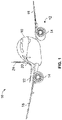
- Figure 1 illustrates a perspective top view of a vehicle, such as an aircraft 10, according to an embodiment of the present disclosure.
- the aircraft 10 includes a propulsion system 12 that may include two turbofan engines 14, for example.
- the propulsion system 12 may include more engines 14 than shown.
- the engines 14 are carried by wings 16 of the aircraft 10.
- the engines 14 may be carried by a fuselage 18 and/or an empennage 20.
- the empennage 20 may also support horizontal stabilizers 22 and a vertical stabilizer 24.
- the fuselage 18 of the aircraft 10 defines an internal cabin, which may be defined by interior sidewall panels that connect to a ceiling and a floor.
- the internal cabin may include a cockpit, one or more work sections (for example, galleys, personnel carry-on baggage areas, and the like), one or more passenger sections (for example, first class, business class, and economy sections), and an aft section in which an aft rest area assembly may be positioned.
- Overhead stowage bin assemblies may be positioned throughout the internal cabin.
- embodiments of the present disclosure may be used with various other vehicles, such as automobiles, buses, locomotives and train cars, seacraft, spacecraft, and the like.
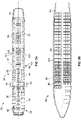
- FIG. 2A illustrates a top plan view of an internal cabin 30 of an aircraft, according to an embodiment of the present disclosure.
- the internal cabin 30 may be within a fuselage 32 of the aircraft.
- one or more fuselage walls may define an interior of the internal cabin 30.
- the interior of the internal cabin 30 is defined by sidewall panels that connect to a ceiling and a floor.
- the sidewall panels include lateral segments that connect to ceiling segments.
- the lateral segments define lateral wall portions, while the ceiling segments define at least portions of the ceiling within the internal cabin 30.
- the internal cabin 30 includes multiple sections, including a front section 33, a first class section 34, a business class section 36, a front galley station 38, an expanded economy or coach section 40, a standard economy or coach section 42, and an aft section 44, which may include multiple lavatories and galley stations. It is to be understood that the internal cabin 30 may include more or less sections than shown. For example, the internal cabin 30 may not include a first class section, and may include more or less galley stations than shown. Each of the sections may be separated by a cabin transition area 46.
- the internal cabin 30 includes two aisles 50 and 52 that lead to the aft section 44.
- the internal cabin 30 may have less or more aisles than shown.
- the internal cabin 30 may include a single aisle that extends through the center of the internal cabin 30 that leads to the aft section 44.
- Seat assemblies 100 are positioned throughout the internal cabin 30.
- the seat assemblies 100 may be arranged in rows 101.
- FIG. 2B illustrates a top plan view of an internal cabin 80 of an aircraft, according to an embodiment of the present disclosure.
- the internal cabin 80 may be within a fuselage 81 of the aircraft.
- one or more fuselage walls may define the interior of the internal cabin 80.
- the internal cabin 80 includes multiple sections, including a main cabin 82 having passenger seat assemblies 100, and an aft section 85 behind the main cabin 82. It is to be understood that the internal cabin 80 may include more or less sections than shown.
- the internal cabin 80 may include a single aisle 84 that leads to the aft section 85.
- the single aisle 84 may extend through the center of the internal cabin 80 that leads to the aft section 85.
- the single aisle 84 may be coaxially aligned with a central longitudinal plane of the internal cabin 80.
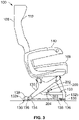
- FIG. 3 illustrates a side view of a seat assembly 100, according to an embodiment of the present disclosure.
- the seat assembly 100 is configured to be secured within an internal cabin of a vehicle, such as a commercial aircraft.
- the seat assembly 100 includes a base 130, which may include legs 132 (such as legs 132a and 132b) that may be secured to seat tracks 134 within a cabin of a vehicle.
- the legs 132 on a same side of the seat assembly 100 may be connected together by a spanner bar 133.
- securing studs 136 (such as shear studs) downwardly extend from lower surfaces 138 of the legs 132.
- the securing studs 136 are securely retained within the seat tracks 134.
- the seat tracks 134 are configured to securely couple to the securing studs 136 to secure the seat assembly 100 in place.
- the base 130 supports a seat cushion 106 and a backrest 108, which includes a headrest 110. Arm rests 140 may be pivotally secured to the backrest 108.
- the seat assembly 100 may be sized and shaped differently than shown in Figure 3 .
- the seat assembly 100 may include more or less components than shown in Figure 3 . It is to be understood that the seat assembly 100 shown in Figure 3 is merely one example of a seat assembly that may be disposed within an internal cabin of a vehicle.
- a seat indexing system 200 includes an indexing wheel 202 coupled to the seat assembly 100.
- the indexing wheel 202 couples to the spanner bar 133 through an extension arm 203 that pivotally couples to the spanner bar 133 via a pivot axle 204.
- the indexing wheel 202 is in a stowed position, in which the indexing wheel 202 is disengaged from the seat track 134.
- the indexing wheel 202 may couple to other portions of the seat assembly 100 other than the spanner bar 133.
- the indexing wheel 202 may be coupled to a leg 132, an underside of the cushion 106, or the like.
- the indexing wheel 202 may be coupled to the seat assembly 100 other than via the extension arm 203.
- the indexing wheel 202 may be coupled to the seat assembly 100 through a retractable, articulating, and/or telescopic assembly.
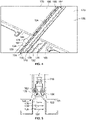
- FIG 4 illustrates a perspective top view of the seat track 134 secured between floor panels 170, according to an embodiment of the present disclosure.
- the seat track 134 includes a base 174 and lateral walls 176 extending upwardly from the base 174.
- a retaining lip 178 inwardly extends from a top end of each lateral wall 176, such as at a ninety-degree angle.
- the retaining lips 178 cooperate to form a series of expanded openings 180 and retaining arms 182 over a track channel 184.
- the expanded openings 180 and retaining arms 182 alternate over a length of the seat track 134. That is, two expanded openings 180 are separated by a retaining arm 182.
- the floor panels 170 include upper planar support surfaces 186 opposite from lower surfaces 188.
- the upper planar surface surfaces 186 connect to the lower surfaces 188 at edges, such as interior edges 190.
- Figure 5 illustrates an end view of a securing stud 136 within a track channel 184 of a seat track 134, according to an embodiment of the present disclosure.
- the securing studs 136 of the seat assembly 100 may have a circular cross section and a width 135 that is less than a width 137 of the expanded openings 180.
- the width 135 is greater than a width 139 of the opening between opposed retaining arms 182.
- the securing studs 136 when the securing studs 136 are shifted into the track channel 184 below or into the expanded openings 180, the securing studs 136, and therefore the legs 132 of the seat assembly 100, may be lifted out of the seat track 134.
- a lock fitting 213 (such as a bolt or other such fastener) is manipulated to unlock the legs 132.
- the lock fitting 213 may be loosened such that a distal end no longer engages a portion of the seat track 134.
- the seat assembly 100 may not include lock fittings.
- the seat assembly 100 may be longitudinally shifted in relation to the seat track 134.
- the seat assembly 100 is shifted so that the securing studs 136 are no longer underneath the retaining arms 182, but are instead within the expanded openings 180.
- the seat assembly 100 may be removed from the seat track 134, and/or moved to a different position on the seat track 134 via a seat adjustment system.
- Figure 6 illustrates a front view of the indexing wheel 202 in a deployed position in relation to the seat track 134, according to an embodiment of the present disclosure.
- the indexing wheel 202 is pivoted downwardly onto the seat track 134, so that the indexing wheel 202 is rotatably supported on the seat track 134.
- the indexing wheel 202 allows for smooth, rolling movement as the seat assembly 100 is moved along the seat track 134 to a different position.
- the indexing wheel 202 is configured to be moved between the stowed position (as shown in Figure 3 ), in which the indexing wheel 202 is disengaged from the seat track 134, and the deployed position (as shown in Figure 6 ), in which the indexing wheel 202 engages the seat track 134. In the deployed position, the indexing wheel 202 rolls over the seat track to identify a proper, desired position for the seat assembly 100 in relation to the seat track.
- the indexing wheel 202 is configured to provide indexing of the seat assembly 100 in relation to the seat track 134, as well as provide an aid for movement of the seat assembly 100 on the seat track 134. That is, the indexing wheel 202 provides smooth, rolling movement on the seat track 134, thereby reducing the need for an individual to remove the seat assembly 100 from the seat track 134 when the seat assembly 100 is moved to a different position on the seat track 134. As such, the indexing wheel 202 bears at least a portion of the weight of the seat assembly 100 during movement to a different position, thereby reducing stress on a mechanic moving the seat assembly 100.
- Figure 7 illustrates a front view of the indexing wheel 202, according to an embodiment of the present disclosure.
- the indexing wheel 202 may include a wheel body 210, a first stop 212 radially extending from the wheel body 210, and a second stop 214 radially extending from the wheel body 210.
- the first stop 212 and the second stop 214 are protuberances, such as beams, posts, spokes, blocks, or the like, which radially extend from the wheel body 210.
- a rolling range 216 of the indexing wheel 202 may be defined between the first stop 212 and the second stop 214.
- the rolling range 216 relates to a traversed area over the seat track 134 defining a proper position for the seat assembly.
- FIG 8 illustrates a front view of the indexing wheel 202, according to an embodiment of the present disclosure.
- the indexing wheel 202 includes a main wheel body 220 and a plurality of knobs 222 radially extending from the wheel body 220. Referring to Figures 3-6 and 8 , the knobs are radially spaced to fit into the expanded openings 180 of the seat track 134 as the indexing wheel 202 rolls over the seat track 134.
- the knobs 222 may be positioned around a circumference of the main wheel body 220.
- the knobs 222 may be positioned around a portion of the circumference of the main wheel body 220, in order to provide an additional indexing aid, as described with respect to Figure 10 .
- FIG 9 illustrates an end view of the indexing wheel 202 in the deployed position, according to an embodiment of the present disclosure.
- the knobs 222 are configured to pass into the expanded openings 180 of the seat track 134. Lateral edges 223 of the wheel body 220 roll over top surfaces of the retaining lips 178. As each knob 222 passes into or out of an expanded opening 180, an audible click may be emitted. The audible click may be caused by an interference between the knobs 222 and the expanded openings 180.
- each knob 222 may be formed of a material, coated with a substance, and/or include a structure (such as a moveable, spring-biased button) that emits a click as it frictionally engages edges of the seat track 134 that define the expanded openings 180.
- a structure such as a moveable, spring-biased button
- an individual may be notified of an incremental movement of the seat assembly 100.
- each passage and/or audible click
- the rolling indexing wheel 202 provides indexing information (such as distance traveled) to an individual.
- FIG 10 illustrates a perspective view of the indexing wheel 202, according to an embodiment of the present disclosure.
- the indexing wheel 202 includes knobs 222, as described above, over a positioning range 230, which relates to a traversed area over the seat track 134 (shown in Figures 3-6 ) defining a proper position for the seat assembly 100, thereby providing a readily apparent indexing aid.
- the positioning range 230 is defined by a plurality of knobs 222.
- a smooth rim 240 is outside of the positioning range 230.
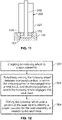
- Figure 11 illustrates an end view of the smooth rim 240 of the indexing wheel 202 in the track channel 184 of the seat track 134, according to an embodiment of the present disclosure.
- the smooth rim 240 may extend into the track channel 184, between the opposed retaining lips 178 to ensure that the indexing wheel 202 remains engaged with the seat track 134, even when the indexing wheel is rolling outside of the positioning range 230 (shown in Figure 10 ).
- the positioning range 230 indicates a start point and an end point for the proper position for the seat assembly 100 on the seat track 134. If the indexing wheel 202 continues to roll on the seat track 134 such that the smooth rim 240 enters the track channel 184, the seat assembly 100 is outside of the proper position.
- FIG 12 illustrates a flow chart of a seat indexing method, according to an embodiment of the present disclosure.
- the seat indexing method includes coupling, at step 300, an indexing wheel to a seat assembly.
- the method includes selectively moving, at step 302, the indexing wheel between a stowed position, in which the indexing wheel is disengaged from a seat track, and a deployed position, in which the indexing wheel engages the seat track.
- the seat indexing method may also include rolling, at step 304, the indexing wheel over a portion of the seat track to identify a proper position for the seat assembly in relation to the seat track.
- the coupling may include coupling the indexing wheel to the seat assembly through an extension arm that is pivotally connected to the seat assembly by a pivot axle.
- the seat indexing method may include providing the indexing wheel with a first stop and a second stop that radially extend from a wheel body.
- the seat indexing method may also include defining a rolling range of the indexing wheel between the first stop and the second stop.
- the seat indexing method may also include relating the rolling range to a traversed area over the seat track defining a proper position for the seat assembly.
- the seat indexing method also includes providing the indexing wheel with a plurality of knobs that radially extend from a wheel body, wherein the plurality of knobs are radially spaced to fit into expanded openings of the seat track as the indexing wheel rolls over the seat track.
- the seat indexing method may also include emitting an audible click as each of the plurality of knobs passes into or out of one of the expanded openings.
- the seat indexing method also includes defining a positioning range with the plurality of knobs.
- the seat indexing method also includes providing a smooth rim outside of the positioning range.
- embodiments of the present disclosure provide an efficient systems and methods for identifying proper locations for seats within an internal cabin of a vehicle. Further, embodiments of the present disclosure provide systems and methods that allow for quick and efficient adjustment of seats within an internal cabin.
- a structure, limitation, or element that is "configured to” perform a task or operation is particularly structurally formed, constructed, or adapted in a manner corresponding to the task or operation.
- an object that is merely capable of being modified to perform the task or operation is not “configured to” perform the task or operation as used herein.
Landscapes
- Engineering & Computer Science (AREA)
- Aviation & Aerospace Engineering (AREA)
- Transportation (AREA)
- Mechanical Engineering (AREA)
- Seats For Vehicles (AREA)
Claims (15)
- Sitzindexierungssystem (200) für einen Innenraum (30, 80) eines Fahrzeugs, wobei das Sitzindexierungssystem (200) Folgendes umfasst:eine Sitzanordnung (100); undein Indexierungsrad (202), das mit der Sitzanordnung (100) gekoppelt ist, wobei das Indexierungsrad (202) dazu konfiguriert ist, zwischen einer eingefahrenen Position, in der das Indexierungsrad (202) von einer Sitzschiene (134) gelöst ist, und einer ausgefahrenen Position, in der das Indexierungsrad (202) in die Sitzschiene (134) eingreift, bewegt zu werden, wobei das Indexierungsrad (202) eine Vielzahl von Knöpfen (222) umfasst, die sich radial von einem Radkörper (210, 220) erstrecken, wobei die Vielzahl von Knöpfen (222) radial beabstandet sind, um in erweiterte Öffnungen (180) der Sitzschiene (134) zu passen,wenn das Indexierungsrad (202) über die Sitzschiene (134) rollt, wobei die Vielzahl von Knöpfen (222) einen Positionierungsbereich (230) definiert, der sich auf einen überquerten Bereich über der Sitzschiene (134) bezieht, welcher eine richtige Position für die Sitzanordnung (100) definiert, wobei das Indexierungsrad (202) ferner eine glatte Felge (240) außerhalb des Positionierungsbereichs (230) umfasst.
- Sitzindexierungssystem (200) nach Anspruch 1, wobei das Indexierungsrad (202) so konfiguriert ist, dass es über einen Abschnitt der Sitzschiene (134) rollt, um eine richtige Position für die Sitzanordnung (100) in Bezug auf die Sitzschiene (134) zu identifizieren.
- Sitzindexierungssystem (200) nach Anspruch 1 oder 2, wobei das Indexierungsrad (202) eine Hilfe für die Bewegung der Sitzanordnung (100) auf der Sitzschiene (134) bereitstellt.
- Sitzindexierungssystem (200) nach Anspruch 1, 2 oder 3, wobei das Indexierungsrad (202) durch einen Verlängerungsarm (203), der über eine Schwenkachse (204) schwenkbar mit der Sitzanordnung (100) verbunden ist, mit der Sitzanordnung (100) gekoppelt ist.
- Sitzindexierungssystem (200) nach einem der Ansprüche 1 bis 4, wobei das Indexierungsrad (202) Folgendes umfasst:einen Radkörper (210, 220);einen ersten Anschlag (212), der sich radial von dem Radkörper (210, 220) erstreckt; undeinen zweiten Anschlag (214), der sich radial von dem Radkörper (210, 220) erstreckt.
- Sitzindexierungssystem (200) nach Anspruch 5, wobei ein Rollbereich (216) des Indexierungsrads (202) zwischen dem ersten Anschlag (212) und dem zweiten Anschlag (214) definiert ist.
- Sitzindexierungssystem (200) nach Anspruch 6, wobei sich der Rollbereich (216) auf einen überquerten Bereich über der Sitzschiene (134) bezieht, der eine geeignete Position für die Sitzanordnung (100) definiert.
- Sitzindexierungssystem (200) nach einem der vorhergehenden Ansprüche, wobei ein hörbares Klicken ausgegeben wird, wenn jeder aus der Vielzahl von Knöpfen (222) in eine oder aus einer der erweiterten Öffnungen (180) gelangt.
- Sitzindexierungsverfahren für einen Innenraum (30, 80) eines Fahrzeugs, wobei das Sitzindexierungsverfahren Folgendes umfasst:Koppeln eines Indexierungsrads (202) an eine Sitzanordnung (100); undselektives Bewegen des Indexierungsrads (202) zwischen einer eingefahrenen Position, in der das Indexierungsrad (202) von einer Sitzschiene (134) gelöst ist, und einer ausgefahrenen Position, in der das Indexierungsrad (202) in die Sitzschiene (134) eingreift, wobei das Indexierungsrad (202) eine Vielzahl von Knöpfen (222) umfasst, die sich radial von einem Radkörper (210, 220) erstrecken, wobei die Vielzahl von Knöpfen (222) radial beabstandet sind, um in erweiterte Öffnungen (180) der Sitzschiene (134) zu passen, wenn das Indexierungsrad (202) über die Sitzschiene (134) rollt, wobei die Vielzahl von Knöpfen (222) einen Positionierungsbereich (230) definiert, der sich auf einen überquerten Bereich über der Sitzschiene (134) bezieht, welcher eine richtige Position für die Sitzanordnung (100) definiert, wobei das Indexierungsrad (202) ferner eine glatte Felge (240) außerhalb des Positionierungsbereichs (230) umfasst.
- Sitzindexierungsverfahren nach Anspruch 9, ferner umfassend das Rollen des Indexierungsrads (202) über einen Abschnitt der Sitzschiene (134), um eine richtige Position für die Sitzanordnung (100) in Bezug auf die Sitzschiene (134) zu identifizieren.
- Sitzindexierungsverfahren nach Anspruch 9 oder 10, wobei das Koppeln das Koppeln des Indexierungsrads (202) mit der Sitzanordnung (100) durch einen Verlängerungsarm (203), der über eine Schwenkachse (204) schwenkbar mit der Sitzanordnung (100) verbunden ist, umfasst.
- Sitzindexierungsverfahren nach Anspruch 9, 10 oder 11, ferner umfassend das Versehen des Indexierungsrads (202) mit einem ersten Anschlag (212) und einem zweiten Anschlag (214), die sich radial von einem Radkörper (210, 220) erstrecken.
- Sitzindexierungsverfahren nach einem der Ansprüche 9 bis 12, ferner umfassend einen Rollbereich (216) des Indexierungsrads (202) zwischen dem ersten Anschlag (212) und dem zweiten Anschlag (214).
- Sitzindizierungsverfahren nach Anspruch 13, ferner umfassend das Beziehen des Rollbereichs (216) auf einen überquerten Bereich über der Sitzschiene (134), der eine richtige Position für die Sitzanordnung (100) definiert.
- Sitzindexierungsverfahren nach einem der Ansprüche 9 bis 14, ferner umfassend das Ausgeben eines hörbaren Klickens, wenn jeder aus der Vielzahl von Knöpfen (222) in eine oder aus einer der erweiterten Öffnungen (180) gelangt.
Applications Claiming Priority (2)
| Application Number | Priority Date | Filing Date | Title |
|---|---|---|---|
| US201962825855P | 2019-03-29 | 2019-03-29 | |
| US16/529,935 US11427328B2 (en) | 2019-03-29 | 2019-08-02 | Seat indexing systems and methods |
Publications (2)
| Publication Number | Publication Date |
|---|---|
| EP3715256A1 EP3715256A1 (de) | 2020-09-30 |
| EP3715256B1 true EP3715256B1 (de) | 2022-05-04 |
Family
ID=70057037
Family Applications (1)
| Application Number | Title | Priority Date | Filing Date |
|---|---|---|---|
| EP20166479.4A Active EP3715256B1 (de) | 2019-03-29 | 2020-03-27 | Sitzindexierungssysteme und -verfahren |
Country Status (2)
| Country | Link |
|---|---|
| US (1) | US11427328B2 (de) |
| EP (1) | EP3715256B1 (de) |
Family Cites Families (17)
| Publication number | Priority date | Publication date | Assignee | Title |
|---|---|---|---|---|
| GB508366A (en) * | 1937-11-26 | 1939-06-26 | Camille Hautier | Variable pitch screw propellers |
| GB608366A (en) | 1945-02-21 | 1948-09-14 | Herbert Rubin | Lamp shades and method of forming same |
| US4723732A (en) * | 1985-09-12 | 1988-02-09 | The Boeing Company | Movable seating system for aircraft |
| GB8705393D0 (en) * | 1987-03-07 | 1987-04-08 | British Aerospace | Seating arrangement for aircraft |
| JPH0674020B2 (ja) | 1989-04-19 | 1994-09-21 | 天龍工業株式会社 | 航空機における客室空間の変更方法及び座席装置 |
| GB9013717D0 (en) | 1990-06-20 | 1990-08-08 | Rumbold Ltd L A | Adjustable passenger seating arrangement |
| US5178346A (en) * | 1991-07-12 | 1993-01-12 | Burns Aerospace Corporation | Track fastener apparatus and assembly |
| GB0323866D0 (en) | 2003-10-11 | 2003-11-12 | Unwin C N Ltd | Furniture anchorages |
| GB0511004D0 (en) | 2005-05-28 | 2005-07-06 | Unwin C N Ltd | Anchorages |
| US7785053B2 (en) | 2006-03-31 | 2010-08-31 | The Boeing Company | Single tough locking seat fittings and methods |
| US7713009B2 (en) | 2006-03-31 | 2010-05-11 | The Boeing Company | Apparatus and methods for removably securing payloads in an aircraft |
| US8128326B2 (en) | 2006-03-31 | 2012-03-06 | The Boeing Company | Apparatus and methods for removably securing payloads in an aircraft |
| GB2477100B (en) | 2010-01-20 | 2016-02-03 | Unwin C N Ltd | Anchorage systems and devices |
| EP2397409B1 (de) * | 2010-06-18 | 2013-09-25 | Bishop GmbH Aeronautical Engineers | Verfahren und System zur flexiblen Sitzanordnung in Flugzeugen |
| US9242580B2 (en) * | 2012-03-30 | 2016-01-26 | Lear Corporation | Vehicle seat memory track assembly with memory adjustment compensation |
| US9567086B2 (en) | 2014-09-17 | 2017-02-14 | The Boeing Company | Systems and methods for securing seats within a vehicle cabin |
| US20170181308A1 (en) * | 2015-12-16 | 2017-06-22 | Tyco Electronics Corporation | Electronic unit hold down assembly |
-
2019
- 2019-08-02 US US16/529,935 patent/US11427328B2/en active Active
-
2020
- 2020-03-27 EP EP20166479.4A patent/EP3715256B1/de active Active
Also Published As
| Publication number | Publication date |
|---|---|
| US20200307809A1 (en) | 2020-10-01 |
| US11427328B2 (en) | 2022-08-30 |
| EP3715256A1 (de) | 2020-09-30 |
Similar Documents
| Publication | Publication Date | Title |
|---|---|---|
| EP2550200B1 (de) | Passagiersitzanordnung mit entsprechender anbringung an flugzeugbodenplatten oder -seitenwänden und verfahren dafür | |
| EP0282244B1 (de) | Einstellung der Sitzanordnung für ein Flugzeug | |
| US9821683B2 (en) | Easy seat positioning and installation | |
| US11560072B2 (en) | Seat track covering systems and methods | |
| US9085367B2 (en) | Apparatus for moving an object on a rail | |
| EP3718893B1 (de) | Komponentenpositionierungssysteme und -verfahren für eine innenkabine eines fahrzeugs | |
| US20200307806A1 (en) | Seat adjustment system and method | |
| US20210188441A1 (en) | Seating arrangement | |
| US11673671B2 (en) | Passenger seating arrangement | |
| EP3680173A1 (de) | Zum sitzen oder verstauen rekonfigurierbarer fahrgastsitz | |
| US20230271706A1 (en) | Seating arrangements for a vehicle cabin | |
| CN110834731A (zh) | 用于飞机客舱的座椅组装置 | |
| EP4353589B1 (de) | Versetzter hubschrauberpilotsitz mit zentriertem vertikalbewegungssystem | |
| EP3715256B1 (de) | Sitzindexierungssysteme und -verfahren | |
| EP3835204B1 (de) | Trägervorrichtung, sitzflächentrenner und fahrzeugkabine | |
| US11197551B2 (en) | Seat transit systems and methods | |
| US10793278B1 (en) | Seat positioning systems and methods | |
| US11572177B2 (en) | Seat cable adjustment system and method | |
| US10926881B2 (en) | Seat adjustment system and method | |
| US11124303B2 (en) | Seat indexing systems and methods | |
| US11866176B2 (en) | Variable reclination backrest for a seat assembly | |
| US11472553B2 (en) | Ceiling retaining assemblies and methods for an internal cabin of a vehicle |
Legal Events
| Date | Code | Title | Description |
|---|---|---|---|
| PUAI | Public reference made under article 153(3) epc to a published international application that has entered the european phase |
Free format text: ORIGINAL CODE: 0009012 |
|
| STAA | Information on the status of an ep patent application or granted ep patent |
Free format text: STATUS: THE APPLICATION HAS BEEN PUBLISHED |
|
| AK | Designated contracting states |
Kind code of ref document: A1 Designated state(s): AL AT BE BG CH CY CZ DE DK EE ES FI FR GB GR HR HU IE IS IT LI LT LU LV MC MK MT NL NO PL PT RO RS SE SI SK SM TR |
|
| AX | Request for extension of the european patent |
Extension state: BA ME |
|
| STAA | Information on the status of an ep patent application or granted ep patent |
Free format text: STATUS: REQUEST FOR EXAMINATION WAS MADE |
|
| 17P | Request for examination filed |
Effective date: 20210323 |
|
| RBV | Designated contracting states (corrected) |
Designated state(s): AL AT BE BG CH CY CZ DE DK EE ES FI FR GB GR HR HU IE IS IT LI LT LU LV MC MK MT NL NO PL PT RO RS SE SI SK SM TR |
|
| RIC1 | Information provided on ipc code assigned before grant |
Ipc: B60N 2/02 20060101ALN20210927BHEP Ipc: H04L 29/08 20060101ALN20210927BHEP Ipc: B64D 45/00 20060101ALN20210927BHEP Ipc: B64D 47/00 20060101ALN20210927BHEP Ipc: B60N 2/36 20060101ALN20210927BHEP Ipc: B60N 2/015 20060101ALN20210927BHEP Ipc: B60N 2/01 20060101ALN20210927BHEP Ipc: B60N 2/005 20060101ALN20210927BHEP Ipc: B64D 11/06 20060101AFI20210927BHEP |
|
| GRAP | Despatch of communication of intention to grant a patent |
Free format text: ORIGINAL CODE: EPIDOSNIGR1 |
|
| STAA | Information on the status of an ep patent application or granted ep patent |
Free format text: STATUS: GRANT OF PATENT IS INTENDED |
|
| INTG | Intention to grant announced |
Effective date: 20211108 |
|
| GRAS | Grant fee paid |
Free format text: ORIGINAL CODE: EPIDOSNIGR3 |
|
| GRAA | (expected) grant |
Free format text: ORIGINAL CODE: 0009210 |
|
| STAA | Information on the status of an ep patent application or granted ep patent |
Free format text: STATUS: THE PATENT HAS BEEN GRANTED |
|
| AK | Designated contracting states |
Kind code of ref document: B1 Designated state(s): AL AT BE BG CH CY CZ DE DK EE ES FI FR GB GR HR HU IE IS IT LI LT LU LV MC MK MT NL NO PL PT RO RS SE SI SK SM TR |
|
| REG | Reference to a national code |
Ref country code: GB Ref legal event code: FG4D |
|
| REG | Reference to a national code |
Ref country code: CH Ref legal event code: EP |
|
| REG | Reference to a national code |
Ref country code: AT Ref legal event code: REF Ref document number: 1488822 Country of ref document: AT Kind code of ref document: T Effective date: 20220515 |
|
| REG | Reference to a national code |
Ref country code: IE Ref legal event code: FG4D Ref country code: DE Ref legal event code: R096 Ref document number: 602020002940 Country of ref document: DE |
|
| REG | Reference to a national code |
Ref country code: LT Ref legal event code: MG9D |
|
| REG | Reference to a national code |
Ref country code: NL Ref legal event code: MP Effective date: 20220504 |
|
| REG | Reference to a national code |
Ref country code: AT Ref legal event code: MK05 Ref document number: 1488822 Country of ref document: AT Kind code of ref document: T Effective date: 20220504 |
|
| PG25 | Lapsed in a contracting state [announced via postgrant information from national office to epo] |
Ref country code: SE Free format text: LAPSE BECAUSE OF FAILURE TO SUBMIT A TRANSLATION OF THE DESCRIPTION OR TO PAY THE FEE WITHIN THE PRESCRIBED TIME-LIMIT Effective date: 20220504 Ref country code: PT Free format text: LAPSE BECAUSE OF FAILURE TO SUBMIT A TRANSLATION OF THE DESCRIPTION OR TO PAY THE FEE WITHIN THE PRESCRIBED TIME-LIMIT Effective date: 20220905 Ref country code: NO Free format text: LAPSE BECAUSE OF FAILURE TO SUBMIT A TRANSLATION OF THE DESCRIPTION OR TO PAY THE FEE WITHIN THE PRESCRIBED TIME-LIMIT Effective date: 20220804 Ref country code: NL Free format text: LAPSE BECAUSE OF FAILURE TO SUBMIT A TRANSLATION OF THE DESCRIPTION OR TO PAY THE FEE WITHIN THE PRESCRIBED TIME-LIMIT Effective date: 20220504 Ref country code: LT Free format text: LAPSE BECAUSE OF FAILURE TO SUBMIT A TRANSLATION OF THE DESCRIPTION OR TO PAY THE FEE WITHIN THE PRESCRIBED TIME-LIMIT Effective date: 20220504 Ref country code: HR Free format text: LAPSE BECAUSE OF FAILURE TO SUBMIT A TRANSLATION OF THE DESCRIPTION OR TO PAY THE FEE WITHIN THE PRESCRIBED TIME-LIMIT Effective date: 20220504 Ref country code: GR Free format text: LAPSE BECAUSE OF FAILURE TO SUBMIT A TRANSLATION OF THE DESCRIPTION OR TO PAY THE FEE WITHIN THE PRESCRIBED TIME-LIMIT Effective date: 20220805 Ref country code: FI Free format text: LAPSE BECAUSE OF FAILURE TO SUBMIT A TRANSLATION OF THE DESCRIPTION OR TO PAY THE FEE WITHIN THE PRESCRIBED TIME-LIMIT Effective date: 20220504 Ref country code: ES Free format text: LAPSE BECAUSE OF FAILURE TO SUBMIT A TRANSLATION OF THE DESCRIPTION OR TO PAY THE FEE WITHIN THE PRESCRIBED TIME-LIMIT Effective date: 20220504 Ref country code: BG Free format text: LAPSE BECAUSE OF FAILURE TO SUBMIT A TRANSLATION OF THE DESCRIPTION OR TO PAY THE FEE WITHIN THE PRESCRIBED TIME-LIMIT Effective date: 20220804 Ref country code: AT Free format text: LAPSE BECAUSE OF FAILURE TO SUBMIT A TRANSLATION OF THE DESCRIPTION OR TO PAY THE FEE WITHIN THE PRESCRIBED TIME-LIMIT Effective date: 20220504 |
|
| PG25 | Lapsed in a contracting state [announced via postgrant information from national office to epo] |
Ref country code: RS Free format text: LAPSE BECAUSE OF FAILURE TO SUBMIT A TRANSLATION OF THE DESCRIPTION OR TO PAY THE FEE WITHIN THE PRESCRIBED TIME-LIMIT Effective date: 20220504 Ref country code: PL Free format text: LAPSE BECAUSE OF FAILURE TO SUBMIT A TRANSLATION OF THE DESCRIPTION OR TO PAY THE FEE WITHIN THE PRESCRIBED TIME-LIMIT Effective date: 20220504 Ref country code: LV Free format text: LAPSE BECAUSE OF FAILURE TO SUBMIT A TRANSLATION OF THE DESCRIPTION OR TO PAY THE FEE WITHIN THE PRESCRIBED TIME-LIMIT Effective date: 20220504 Ref country code: IS Free format text: LAPSE BECAUSE OF FAILURE TO SUBMIT A TRANSLATION OF THE DESCRIPTION OR TO PAY THE FEE WITHIN THE PRESCRIBED TIME-LIMIT Effective date: 20220904 |
|
| PG25 | Lapsed in a contracting state [announced via postgrant information from national office to epo] |
Ref country code: SM Free format text: LAPSE BECAUSE OF FAILURE TO SUBMIT A TRANSLATION OF THE DESCRIPTION OR TO PAY THE FEE WITHIN THE PRESCRIBED TIME-LIMIT Effective date: 20220504 Ref country code: SK Free format text: LAPSE BECAUSE OF FAILURE TO SUBMIT A TRANSLATION OF THE DESCRIPTION OR TO PAY THE FEE WITHIN THE PRESCRIBED TIME-LIMIT Effective date: 20220504 Ref country code: RO Free format text: LAPSE BECAUSE OF FAILURE TO SUBMIT A TRANSLATION OF THE DESCRIPTION OR TO PAY THE FEE WITHIN THE PRESCRIBED TIME-LIMIT Effective date: 20220504 Ref country code: EE Free format text: LAPSE BECAUSE OF FAILURE TO SUBMIT A TRANSLATION OF THE DESCRIPTION OR TO PAY THE FEE WITHIN THE PRESCRIBED TIME-LIMIT Effective date: 20220504 Ref country code: DK Free format text: LAPSE BECAUSE OF FAILURE TO SUBMIT A TRANSLATION OF THE DESCRIPTION OR TO PAY THE FEE WITHIN THE PRESCRIBED TIME-LIMIT Effective date: 20220504 Ref country code: CZ Free format text: LAPSE BECAUSE OF FAILURE TO SUBMIT A TRANSLATION OF THE DESCRIPTION OR TO PAY THE FEE WITHIN THE PRESCRIBED TIME-LIMIT Effective date: 20220504 |
|
| REG | Reference to a national code |
Ref country code: DE Ref legal event code: R097 Ref document number: 602020002940 Country of ref document: DE |
|
| PLBE | No opposition filed within time limit |
Free format text: ORIGINAL CODE: 0009261 |
|
| STAA | Information on the status of an ep patent application or granted ep patent |
Free format text: STATUS: NO OPPOSITION FILED WITHIN TIME LIMIT |
|
| RAP4 | Party data changed (patent owner data changed or rights of a patent transferred) |
Owner name: THE BOEING COMPANY |
|
| PG25 | Lapsed in a contracting state [announced via postgrant information from national office to epo] |
Ref country code: AL Free format text: LAPSE BECAUSE OF FAILURE TO SUBMIT A TRANSLATION OF THE DESCRIPTION OR TO PAY THE FEE WITHIN THE PRESCRIBED TIME-LIMIT Effective date: 20220504 |
|
| 26N | No opposition filed |
Effective date: 20230207 |
|
| PG25 | Lapsed in a contracting state [announced via postgrant information from national office to epo] |
Ref country code: SI Free format text: LAPSE BECAUSE OF FAILURE TO SUBMIT A TRANSLATION OF THE DESCRIPTION OR TO PAY THE FEE WITHIN THE PRESCRIBED TIME-LIMIT Effective date: 20220504 |
|
| P01 | Opt-out of the competence of the unified patent court (upc) registered |
Effective date: 20230516 |
|
| PG25 | Lapsed in a contracting state [announced via postgrant information from national office to epo] |
Ref country code: MC Free format text: LAPSE BECAUSE OF FAILURE TO SUBMIT A TRANSLATION OF THE DESCRIPTION OR TO PAY THE FEE WITHIN THE PRESCRIBED TIME-LIMIT Effective date: 20220504 |
|
| REG | Reference to a national code |
Ref country code: CH Ref legal event code: PL |
|
| REG | Reference to a national code |
Ref country code: BE Ref legal event code: MM Effective date: 20230331 |
|
| PG25 | Lapsed in a contracting state [announced via postgrant information from national office to epo] |
Ref country code: LU Free format text: LAPSE BECAUSE OF NON-PAYMENT OF DUE FEES Effective date: 20230327 |
|
| REG | Reference to a national code |
Ref country code: IE Ref legal event code: MM4A |
|
| PG25 | Lapsed in a contracting state [announced via postgrant information from national office to epo] |
Ref country code: LI Free format text: LAPSE BECAUSE OF NON-PAYMENT OF DUE FEES Effective date: 20230331 Ref country code: IT Free format text: LAPSE BECAUSE OF FAILURE TO SUBMIT A TRANSLATION OF THE DESCRIPTION OR TO PAY THE FEE WITHIN THE PRESCRIBED TIME-LIMIT Effective date: 20220504 Ref country code: IE Free format text: LAPSE BECAUSE OF NON-PAYMENT OF DUE FEES Effective date: 20230327 Ref country code: CH Free format text: LAPSE BECAUSE OF NON-PAYMENT OF DUE FEES Effective date: 20230331 |
|
| PG25 | Lapsed in a contracting state [announced via postgrant information from national office to epo] |
Ref country code: BE Free format text: LAPSE BECAUSE OF NON-PAYMENT OF DUE FEES Effective date: 20230331 |
|
| PG25 | Lapsed in a contracting state [announced via postgrant information from national office to epo] |
Ref country code: BG Free format text: LAPSE BECAUSE OF FAILURE TO SUBMIT A TRANSLATION OF THE DESCRIPTION OR TO PAY THE FEE WITHIN THE PRESCRIBED TIME-LIMIT Effective date: 20220504 |
|
| PG25 | Lapsed in a contracting state [announced via postgrant information from national office to epo] |
Ref country code: BG Free format text: LAPSE BECAUSE OF FAILURE TO SUBMIT A TRANSLATION OF THE DESCRIPTION OR TO PAY THE FEE WITHIN THE PRESCRIBED TIME-LIMIT Effective date: 20220504 |
|
| PGFP | Annual fee paid to national office [announced via postgrant information from national office to epo] |
Ref country code: DE Payment date: 20250327 Year of fee payment: 6 |
|
| PGFP | Annual fee paid to national office [announced via postgrant information from national office to epo] |
Ref country code: FR Payment date: 20250325 Year of fee payment: 6 |
|
| PGFP | Annual fee paid to national office [announced via postgrant information from national office to epo] |
Ref country code: GB Payment date: 20250327 Year of fee payment: 6 |
|
| PG25 | Lapsed in a contracting state [announced via postgrant information from national office to epo] |
Ref country code: CY Free format text: LAPSE BECAUSE OF FAILURE TO SUBMIT A TRANSLATION OF THE DESCRIPTION OR TO PAY THE FEE WITHIN THE PRESCRIBED TIME-LIMIT; INVALID AB INITIO Effective date: 20200327 |
|
| PG25 | Lapsed in a contracting state [announced via postgrant information from national office to epo] |
Ref country code: HU Free format text: LAPSE BECAUSE OF FAILURE TO SUBMIT A TRANSLATION OF THE DESCRIPTION OR TO PAY THE FEE WITHIN THE PRESCRIBED TIME-LIMIT; INVALID AB INITIO Effective date: 20200327 |
|
| PG25 | Lapsed in a contracting state [announced via postgrant information from national office to epo] |
Ref country code: TR Free format text: LAPSE BECAUSE OF FAILURE TO SUBMIT A TRANSLATION OF THE DESCRIPTION OR TO PAY THE FEE WITHIN THE PRESCRIBED TIME-LIMIT Effective date: 20220504 |