EP3715210A1 - Method and system for localizing a railway vehicle, and related railway vehicle - Google Patents
Method and system for localizing a railway vehicle, and related railway vehicle Download PDFInfo
- Publication number
- EP3715210A1 EP3715210A1 EP20166144.4A EP20166144A EP3715210A1 EP 3715210 A1 EP3715210 A1 EP 3715210A1 EP 20166144 A EP20166144 A EP 20166144A EP 3715210 A1 EP3715210 A1 EP 3715210A1
- Authority
- EP
- European Patent Office
- Prior art keywords
- railway vehicle
- railway
- localizing
- video data
- line
- Prior art date
- Legal status (The legal status is an assumption and is not a legal conclusion. Google has not performed a legal analysis and makes no representation as to the accuracy of the status listed.)
- Withdrawn
Links
- 238000000034 method Methods 0.000 title claims abstract description 15
- 239000003550 marker Substances 0.000 claims abstract description 24
- 238000012545 processing Methods 0.000 claims abstract description 16
- 230000004438 eyesight Effects 0.000 claims description 8
- 230000001133 acceleration Effects 0.000 claims description 6
- 230000007704 transition Effects 0.000 description 8
- 238000005259 measurement Methods 0.000 description 6
- 230000008859 change Effects 0.000 description 5
- 230000004807 localization Effects 0.000 description 3
- 238000010276 construction Methods 0.000 description 2
- 230000003137 locomotive effect Effects 0.000 description 2
- 238000004891 communication Methods 0.000 description 1
- 230000002860 competitive effect Effects 0.000 description 1
- 238000010586 diagram Methods 0.000 description 1
- 230000007613 environmental effect Effects 0.000 description 1
- 239000000284 extract Substances 0.000 description 1
- 230000000977 initiatory effect Effects 0.000 description 1
- 238000009434 installation Methods 0.000 description 1
- 238000012423 maintenance Methods 0.000 description 1
- 238000012986 modification Methods 0.000 description 1
- 230000004048 modification Effects 0.000 description 1
- 230000004297 night vision Effects 0.000 description 1
- 230000008569 process Effects 0.000 description 1
- 238000005070 sampling Methods 0.000 description 1
- 238000012546 transfer Methods 0.000 description 1
Images


Classifications
-
- B—PERFORMING OPERATIONS; TRANSPORTING
- B61—RAILWAYS
- B61L—GUIDING RAILWAY TRAFFIC; ENSURING THE SAFETY OF RAILWAY TRAFFIC
- B61L23/00—Control, warning or like safety means along the route or between vehicles or trains
- B61L23/04—Control, warning or like safety means along the route or between vehicles or trains for monitoring the mechanical state of the route
- B61L23/041—Obstacle detection
-
- B—PERFORMING OPERATIONS; TRANSPORTING
- B61—RAILWAYS
- B61L—GUIDING RAILWAY TRAFFIC; ENSURING THE SAFETY OF RAILWAY TRAFFIC
- B61L25/00—Recording or indicating positions or identities of vehicles or trains or setting of track apparatus
- B61L25/02—Indicating or recording positions or identities of vehicles or trains
- B61L25/025—Absolute localisation, e.g. providing geodetic coordinates
Definitions
- the present invention relates to a method and a system for localizing a railway vehicle travelling along a railway line, and to a related railway vehicle.
- an important aspect is related to the possibility of precisely and timely localizing the position of railways vehicles during their service.
- balises installed along the railway track and adapted to wirelessly communicate with a railway vehicle passing over the balise or track circuits.
- a main aim of the present invention is to provide a solution for a more timely and precise localization of a railway vehicle travelling along a railway line, in particular without the need of installing on the railway line additional equipment provided ad hoc for localization purposes.
- an object of the present invention is to provide a solution which allows localizing the actual position of a railway vehicle along a railway line in a manner that substantially reduces, if not completely eliminates, the influence of external and/or operative conditions, such as darkness, the presence of snow, and the like.
- Another object of the present invention is to provide a solution which allows localizing the actual position of a railway vehicle autonomously by the rail vehicle itself.
- Yet a further object of the present invention is to provide a solution for the localization of a railway vehicle travelling along a railway line, which is highly reliable, relatively easy to realize and implement at competitive costs.
- a system for localizing a railway vehicle traveling on a railway line characterized in that it comprises at least:
- a method for localizing a railway vehicle traveling on a railway line characterized in that it comprises at least the following steps:
- the present invention also provides a railway vehicle characterized in that it comprises, preferably installed on-board, at least one localizing system according to the relevant appended claims, and as per details given in the following description.
- each of the above listed terms means and encompasses electronic circuits or parts thereof, as well as stored, embedded or running software codes and/or routines, algorithms, or complete programs, suitably designed for achieving the technical result and/or the functional performances for which such means are devised.
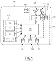
- a system for localizing a railway vehicle travelling along a railway line according to the invention is schematically illustrated in figure 1 and therein indicated by the overall reference number 100, hereinafter referred to as the localizing system 100.
- the localizing system 100 can be used in connection with any suitable type of railway vehicle, an example of which is illustrated in figure 2 in the schematic form of a train 1, having a locomotive 2 and two carriages 3, travelling along a railway line 10.
- railway vehicle herein used encompasses any suitable type of railway vehicle which can be composed by any number of locomotives or equivalent traction units, and associated one or more carriages, railcars, vehicles, or the like.
- the localizing system 100 comprises at least:
- the localizing system 100 comprises a processing unit 140 which is arranged to calculate the actual position (Pa) of the railway vehicle 1 along the railway line 10 based on one or more of the identified presence of a position marker 4 and of the signals received from the plurality of sensors 110.
- the processing unit 140 comprises a processor, or processor-based device or controller, and can comprise any suitable type of commercially available processor or microprocessor suitably programmed with software, to the extent needed accompanied with suitable circuitry, for performing the functionalities it is used for.
- the localizing system 100 is particularly suitable for being used in connection with railway lines associated with power aerial lines, i. e. the so-called catenaries, which electrically supply railway vehicles travelling over an associated railway line.
- Such catenaries comprise a plurality of catenary cantilever poles distributed along a railway line, such as the railway line 10, spaced apart from each other, for example at regular intervals of 50-60 meters.
- the plurality of sensors 110 comprises at least one multi-axis inertial sensor.
- the at least one multi-axis inertial sensor comprises at least a multi-axis gravimeter 111, and/or at least a multi-axis gyroscope 112, and/or at least a multi-axis accelerometer 113.
- the localizing system 100 comprises a three-axis gravimeter 111, a three-axis gyroscope 112, and a three-axis accelerometer 113.
- the localizing system 100 comprises also at least a multi-axis magnetometer 115, preferably a three-axis magnetometer 115.
- the various multi-axis sensors above mentioned can be constituted by commercially available MEMS sensors.
- the multi-axis gravimeter 111 installed on-board of the railway vehicle 1, is a type of accelerometer adapted to detect the value of the gravitational field in a location where the railway vehicle 1 is actually located, and to provide corresponding signals indicative of such local gravitational field to the processing unit 140.
- the multi-axis magnetometer 115 installed on-board of the railway vehicle 1, is adapted to detect the value of the magnetic field strength at a location where the railway vehicle 1 is actually located, and to provide corresponding signals indicative of such local magnetic field strength to the processing unit 140.
- the multi-axis gyroscope 112 installed on-board of the railway vehicle 1, is adapted to detect rotational or angular movements of the railway vehicle 1, and in particular it is aimed at providing the processing unit 140 with signals indicative of track changeovers encountered by the railway vehicle 1 during its travel along the railway line 10, thus detecting when the railway vehicle 1 has deviated from the previous direction due to the presence of points along the line.
- the multi-axis accelerometer 113 installed on-board of the railway vehicle 1, is adapted to detect, e.g. continuously, the actual acceleration of the railway vehicle 1 and to provide corresponding signals indicative of such actual acceleration to the processing unit 140.
- the multi-axis accelerometer 113 is used in connection with a Kalman filter algorithm 114 which filters out random white noise from the measurements of the accelerometer 113.
- a Kalman filter algorithm 114 which filters out random white noise from the measurements of the accelerometer 113.
- the signals provided by one or more of the plurality of sensors 110 are used by the processing unit 140 for calculating corresponding one or more quaternions.
- the video system 120 comprises at least a first camera 121 mounted on-board the railway vehicle 1 with its field of vision oriented opposite to the direction of travel of the railway vehicle 1 and a second camera 122 mounted on-board of the railway vehicle 1 with its field of vision oriented in the direction of travel of the railway vehicle 1.
- the position of the first and second cameras 121 and 122 can be suitably selected, for example they can be positioned outside of and at a forward zone of the rail vehicle 1.
- the cameras 121 and 122 can be placed over the roof of the first railway vehicle 1, spaced apart from each other.
- the video processor 125 is arranged to identify the presence of a position marker 4, namely of a catenary pole 4, when both the video data captured by the first camera 121 and by the second camera 122 match with corresponding pre-stored first video data and second video data related to the pre-installed catenary poles 4.
- the video system 120 can further comprise a third camera 123 mounted on-board of the railway vehicle 1 with its field of vision oriented opposite the direction of travel of the railway vehicle 1, and a fourth camera 124 mounted on-board of the railway vehicle 1 with its field of vision oriented in the direction of travel of the railway vehicle 1.
- the third and fourth cameras 123 and 124 can transfer the video data captured to the video processor 125, or they can be associated to a further video processor, not illustrated, substantially equivalent to the video processor 125.
- the third and fourth cameras 123 and 124 are mounted on the railway vehicle 1 at a predetermined distance from each other; in particular, the position of the third and fourth camera can be suitably selected relative to each other and to the first and second cameras 121, 122. For instance, they can be positioned outside of and at a backward zone of the rail vehicle 1. For example, in case of a multi-vehicle convoy, the cameras 123 and 124 can be placed over the roof of the last railway vehicle 1, suitably spaced apart from each other.
- the first and third cameras 121, 123 are mounted on the railway vehicle 1 at a predetermined distance from each other, and capture both substantially the same video data of a catenary pole 4 with a time delay between each other; likewise, the second and fourth cameras 122, 124 are mounted on the railway vehicle 1 at a corresponding predetermined distance from each other, and correspondingly capture substantially the same video data (different from those captured by the first and third cameras 121 and 123) of a catenary pole 4 with a time delay between each other.
- Each of the cameras used can be a high-speed camera with night vision capabilities of any suitable type commercially available.
- the localizing system 100 comprises one or more databases 150 including:
- the repositories 151-154 have been illustrated as separate databases, such as a catenary pole-cantilever database 151, a catenary pole database 152, an interstation track transition database 153, and a catenary pole-track quaternion database 154; of course, they can be part of a same database or they can be merged in a number of databases different from that illustrated.
- the localizing system 100 can also comprise a device 160, e.g. a transceiver, for communicating data on board of the train itself, or outside.
- a device 160 e.g. a transceiver
- the various parts and components of the localizing system 100 are suitably and completely installed on-board of a railway vehicle 1, which is therefore capable of autonomously self-locating its position along a railway line over which it is travelling.
- the localizing system 100 can have some parts mounted on-board and some others can be located remotely, e.g. in a main control room of the railway line 10.
- Figure 4 illustrates a method 200 for localizing a railway vehicle 1 traveling on a railway line 10 according to the present invention, which comprises at least the following steps:
- the step 220 of comparing comprises a sub-step 222 of identifying the presence of a position marker 4 along the railway line 1 when the captured first video data and captured second video data, which are different from the first video data captured, match both with corresponding pre-stored first video data and second video data related to the position markers 4.
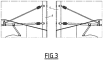
- the video processor 125 receives a video from a camera, extracts video data, e.g. images, from the video and compares them with reference video data, e.g. images, of catenary poles images, as those illustrated in figure 3 . In this way is possible to identify and confirm the presence of a catenary pole 4.
- the first camera 121 and the second camera 122 when two cameras are used, e.g. the first camera 121 and the second camera 122, they take a video continuously with the second camera 122 capturing a catenary pole 4 first, and then the first camera 121 sees the same pole 4 once the railway vehicle 1 passes over it.
- the video processor 125 receives both videos, which are for instance related to an anterior part of a pole 4 and to a posterior part of the same pole 4, and compares them with corresponding pre-stored video data. In this way the safety of correctly identifying the presence of a pole 4 is further increased.
- the step 210 of providing a plurality of signals comprises providing, e.g. via the multi-axis gravimeter 111, a first signal indicative of the value of the gravitational field at the actual position of the railway vehicle 1, and/or a second signal, e.g. via the multi-axis magnetometer 115, indicative of the value of the magnetic field strength at the actual position of the railway vehicle 1.
- the step 230 of calculating the actual position Pa of the railway vehicle 1 comprises initializing the position of the railway vehicle 1 along the railway line 10 based on at least one of, preferably the combination of, the first signal provided indicative of the value of the gravitational field, and/or the second signal indicative of the value of the magnetic field strength.
- the step 210 of providing a plurality of signals comprises providing, e.g. via the multi-axis accelerometer 113, signals indicative of the actual acceleration of the railway vehicle 1, which signals are preferably filtered by a Kalman filter algorithm 114 before inputting to the processing unit 140.
- the step 230 comprises calculating the actual position Pa of the railway vehicle 1 between a first position marker 4, whose presence has been identified, and a following position marker 4 to be reached by the travelling railway vehicle 1, based on the provided signals indicative of the actual acceleration of the railway vehicle 1, and relatively to the first position marker 4 the presence of which was previously identified.
- the location of a pole 4 whose presence is identified is recurrently used for resetting measurements of actual distances in the Kalman filter algorithm 114.
- the step 210 of providing a plurality of signals comprises providing signals indicative of an angular or rotational movement of the railway vehicle 1 with respect to a preceding substantially rectilinear movement, thus allowing to detect that the railway vehicle 1 has encountered a track changeover along its path, e.g. a point branching the previous direction with a left branch or a right branch of the railway line 10.
- the step 230 of calculating the actual position Pa of the railway vehicle 1 along the railway line 10 comprises continuously updating one or more quaternions, e.g. in the fourth repository 154, which are calculated based on corresponding one or more signals provided among the plurality of signals suitable for calculating a position P of the railway vehicle 1 along the railway line 10.
- a railway vehicle 1 when a railway vehicle 1 enters into service for the first time of day, e.g. moving from a depot to a starting station, its absolute position can be initially and unambiguously localized by means of the signals indicative of the local gravitational field and/or of the local magnetic field strength provided by the multi-axis gravimeter 111 and/or by the multi-axis magnetometer 115 which are provided to the processing unit 140.
- the processing unit 140 calculates such initial position by elaborating quaternions, for instance based on the combination of both the signals indicative of the local gravitational field and of the local magnetic field strength.
- the pole identification is performed for example in the fourth repository 154.
- the processing unit 140 calculates also quaternions based on corresponding signals provided by the multi-axis gyroscope 112 and the accelerometer 113-Kalman filter 114.
- the unique catenary pole 4 is not identified yet, while the railway vehicle 1 is running towards the following catenary pole 4, a combination of magnetometer, 115, gravimeter 111 and gyroscope 112 quaternions can be used at each distance measured using the signals provided by the accelerometer 113. Accordingly, in-between two poles at inter-station areas, the catenary poles 4 can be identified. If still the unique identification of a catenary pole 4 is not achieved, multiple catenary pole section data are used.
- Each and any of the quaternions can be continuously calculated and updated for example in the fourth repository 154.
- the gyroscope quaternion is initialized or reset with a default value.
- the quaternion calculated based on the signals provided by the multi-axis magnetometer 115 and multi-axis gravimeter 111 can be used for performing a pole identification in the fourth repository 154.
- the track location is initialized, as well as the catenary pole location.
- the catenary pole identification number is for example incremented automatically onboard of the railway vehicle 1, and respective catenary pole data are extracted from the second repository 152, e.g. the "Catenary pole database".
- the distance at the section between two poles is continuously measured using the accelerometer 113 along with the Kalman filter 114 which helps to propagate the train location continuously till the next catenary pole 4.
- Such distance can be measured for example at sampling values of the accelerometer 113, e.g. 100 HZ.
- the gyroscope-based quaternion and the magnetometer-gravimeter-based quaternion are calculated and updated into the fourth repository 154.
- the track changeover is identified using the signals provided by the multi-axis gyroscope 112.
- operative conditions can be detected by using for example the quaternions calculated based on the signals provided by the multi-axis gyroscope 112 and by using the relevant data stored in the third repository 153, e.g. the interstation track transition database, such as the identification data for the first catenary pole 4 after the relevant point or track changeover.
- the third repository or interstation track transition database 153 is updated at each track change over.
- the interstation name/ID is assigned by concatenating two station names or IDs.
- the catenary pole identification number at which track changeover occurs is assigned.
- the rotational angle at which change over occurs is recorded using measurements of the gyroscope 112.
- the first catenary pole ID at the new track and change over track ID are assigned.
- the first repository or catenary pole cantilever image database 151 is updated at each track change over.
- the second repository of catenary pole database is updated at each catenary pole.
- the interstation name/ID is assigned, for example by concatenating two station names or IDs.
- the catenary pole identification number and track ID are initialized for example at "1", which is the first pole the vehicle encounters just after a station. At this time, the location 100c point is initialized with "0".
- the location value is assigned with the sum of location value of the previous pole and the distance traveled till reaching the current pole.
- the track-ID change over occurs at points/switches detected using gyroscope measurement, as above indicated.
- the upcoming left track transition ID and upcoming right track transition ID are updated based on the switches/points along the track.
- the upcoming pole ID is updated according to new pole ID after the creation in the database.
- the entire database construction is repeated at each location of the track where the catenary poles are mounted along the track always to start with respect to a particular station and inter-station.
- the same database construction process has to be repeated to cover each section of a track in both directions of travel i.e. from a departure station to a destination station, or vice versa.
- a third camera 123 and a fourth camera 124 When a third camera 123 and a fourth camera 124 are used they can be used for redundancy, e.g. for replacing the first camera 121 or the second camera 122, respectively, which may not be working properly for whatever reason, or, they can be suitably used for determining information indicative of the integrity of the rail vehicle 10.
- the rail vehicle 1 is provided with twins localizing systems 100 interchangeable with each other and positioned, for example one at the first wagon of a vehicle and the other at the last wagon.
- control system 100, method 200, and the related railway vehicle 1 achieve the intended aim and objects, since they allow to localize precisely and timely the position of a railway vehicle travelling along a railway line, even completely autonomously by the railway vehicle itself, and also to discriminate the presence and direction of a localized railway vehicle.
- the negative influence of operative and/or environmental conditions is substantially mitigated, if not completely eliminated
- control system 100 may reside on the same electronic unit, or they can even be realized as subparts of a same component or circuit of an electronic unit, or they can be placed remotely from each other and in operative communication there between.
Landscapes
- Engineering & Computer Science (AREA)
- Mechanical Engineering (AREA)
- Train Traffic Observation, Control, And Security (AREA)
- Electric Propulsion And Braking For Vehicles (AREA)
Abstract
Description
- The present invention relates to a method and a system for localizing a railway vehicle travelling along a railway line, and to a related railway vehicle.
- As it is known, railway transportation systems are widely and increasingly used worldwide.
- As a consequence, the growing number of railway vehicles has resulted in increasing the complexity and extension of available infrastructures, such as track layouts and related equipment, as well as of the related control systems which are required to safely manage networks which are more and more congestioned.
- To this end, an important aspect is related to the possibility of precisely and timely localizing the position of railways vehicles during their service.
- In fact, with this information it is possible, for example, to determine if a train is travelling in the right direction and to correlate such information with respect to other trains servicing at the same time in close areas; in this way, it is possible to better manage the whole traffic in a monitored area, and in particular to mitigate the possibility of perturbations and failures of rail systems, and especially to reduce, if not to completely prevent, the risks of collisions.
- To afford such issues, there have been proposed and implemented different solutions, one of which foresees to exploit global positioning systems, or GPS, in order to track the position of railway vehicles travelling on a rail network.
- This solution is not cost effective and in some cases is not truly reliable and efficient, due for instance to accuracy limits which do not allow to clearly identify which track of a pair of sided tracks a train is travelling along, or due to areas not covered by satellites.
- Other solutions used in mainline rail systems foresee to localize trains using balises installed along the railway track and adapted to wirelessly communicate with a railway vehicle passing over the balise or track circuits.
- However, the installation of several balises or track circuits which, for long-distance tracks could be in the order of thousands, is not fully satisfactory in terms of time, cost and maintenance aspects.
- Therefore, there is substantial room and desire for further improvements in the way railway vehicles are localized when travelling along railway lines.
- To this end, a main aim of the present invention is to provide a solution for a more timely and precise localization of a railway vehicle travelling along a railway line, in particular without the need of installing on the railway line additional equipment provided ad hoc for localization purposes.
- Within the scope of this aim, an object of the present invention is to provide a solution which allows localizing the actual position of a railway vehicle along a railway line in a manner that substantially reduces, if not completely eliminates, the influence of external and/or operative conditions, such as darkness, the presence of snow, and the like.
- Another object of the present invention is to provide a solution which allows localizing the actual position of a railway vehicle autonomously by the rail vehicle itself.
- Yet a further object of the present invention is to provide a solution for the localization of a railway vehicle travelling along a railway line, which is highly reliable, relatively easy to realize and implement at competitive costs.
- This aim, these objects and others which will become apparent hereinafter are achieved by a system for localizing a railway vehicle traveling on a railway line, characterized in that it comprises at least:
- a plurality of sensors providing signals suitable for calculating a position of the railway vehicle along the railway line;
- a video system comprising at least one camera mounted on-board of the railway vehicle and adapted to capture video data of position markers located along the railway line, and a video processor which receives the video data captured and compare them with reference pre-stored video data related to the position markers in order to identify the presence of a position marker along the railway line where the railway vehicle is travelling;
- a processing unit which is arranged to calculate the actual position of the railway vehicle along the railway line based on one or more of the identified presence of a position marker and of the signals received from said plurality sensors.
- The above mentioned aim and objects of the present invention are also achieved by a method for localizing a railway vehicle traveling on a railway line, characterized in that it comprises at least the following steps:
- - (a): providing a plurality of signals suitable for calculating a position of the railway vehicle along the railway line;
- - (b): comparing captured video data of position markers located along the railway line with reference pre-stored video data related to said position markers in order to identify the presence of a position marker along the railway line where the railway vehicle is travelling;
- - (c): calculating the actual position of the railway vehicle along the railway line based on one or more of the identified presence of a position marker and of the signals received from said plurality sensors.
- The present invention also provides a railway vehicle characterized in that it comprises, preferably installed on-board, at least one localizing system according to the relevant appended claims, and as per details given in the following description.
- Further characteristics and advantages will become apparent from the description of some preferred but not exclusive exemplary embodiments of a method, system and related railway vehicle according to the invention, illustrated only by way of non-limitative examples with the accompanying drawings, wherein:
-
Figure 1 is a block diagram schematically illustrating a system for localizing a railway vehicle travelling along a railway line according to the invention; -
Figure 2 is a schematic illustration of a railway vehicle having, installed on-board, or in any case using the system depicted infigure 1 ; -
Figure 3 schematically shows exemplary views of catenary poles captured by two cameras mounted on board of a railway vehicle according to the present invention; -
Figure 4 is a flow chart schematically illustrating a method for localizing a railway vehicle travelling along a railway line, according to the invention. - It should be noted that in the detailed description that follows, identical or similar components, either from a structural and/or functional point of view, have the same reference numerals, regardless of whether they are shown in different embodiments of the present disclosure.
- It should be also noted that in order to clearly and concisely describe the present disclosure, the drawings may not necessarily be to scale and certain features of the disclosure may be shown in somewhat schematic form.
- Further, when the term "adapted" or "arranged" or "configured" or "shaped", is used herein while referring to any component as a whole, or to any part of a component, or to a combination of components, it has to be understood that it means and encompasses correspondingly either the structure, and/or configuration and/or form and/or positioning.
- In particular, for electronic and/or software means, each of the above listed terms means and encompasses electronic circuits or parts thereof, as well as stored, embedded or running software codes and/or routines, algorithms, or complete programs, suitably designed for achieving the technical result and/or the functional performances for which such means are devised.
- A system for localizing a railway vehicle travelling along a railway line according to the invention is schematically illustrated in
figure 1 and therein indicated by theoverall reference number 100, hereinafter referred to as the localizingsystem 100. - The localizing
system 100 according to the invention can be used in connection with any suitable type of railway vehicle, an example of which is illustrated infigure 2 in the schematic form of atrain 1, having alocomotive 2 and twocarriages 3, travelling along arailway line 10. - As those skilled in the art would easily appreciated, the term railway vehicle herein used encompasses any suitable type of railway vehicle which can be composed by any number of locomotives or equivalent traction units, and associated one or more carriages, railcars, vehicles, or the like.
- As illustrated in
figure 1 , the localizingsystem 100 according to the present invention comprises at least: - a plurality of
sensors 110 providing signals suitable for calculating a position (P) of therailway vehicle 1 along therailway line 10; - a
video system 120 comprising at least onecamera 121 mounted on-board of therailway vehicle 1 and adapted to capture video data, e.g. images, of a plurality ofpre-installed position markers 4 which are located along therailway line 10, and avideo processor 125 which receives the video data captured by the at least onecamera 121. Thevideo processor 125 compares the video data captured with reference pre-stored video data related to theposition markers 4 in order to identify and confirm the presence of aposition marker 4 along therailway line 10 where therailway vehicle 1 is travelling. - The localizing
system 100 comprises aprocessing unit 140 which is arranged to calculate the actual position (Pa) of therailway vehicle 1 along therailway line 10 based on one or more of the identified presence of aposition marker 4 and of the signals received from the plurality ofsensors 110. - The
processing unit 140 comprises a processor, or processor-based device or controller, and can comprise any suitable type of commercially available processor or microprocessor suitably programmed with software, to the extent needed accompanied with suitable circuitry, for performing the functionalities it is used for. - Further, the localizing
system 100 according to the present invention is particularly suitable for being used in connection with railway lines associated with power aerial lines, i. e. the so-called catenaries, which electrically supply railway vehicles travelling over an associated railway line. - Such catenaries, according to solutions well known in the art, and therefore not described herein in details, comprise a plurality of catenary cantilever poles distributed along a railway line, such as the
railway line 10, spaced apart from each other, for example at regular intervals of 50-60 meters. - Hence, for the sake of illustration of the localizing
system 100, in the following description, when referring to position markers located along a railway line, reference will be made specifically to cantilever poles of a catenary, schematic examples of which are represented infigures 2 and3 by thereference number 4. - Clearly, such reference should not be intended in any way as limiting the application of the localizing
system 100 according to the invention to other types of railway lines provided with different type of pre-installed parts or equipment distributed along the railway line and which may serve as position markers for the scope of the present invention, likewise thecantilever poles 4. - According to a possible embodiment of the localizing
system 100, the plurality ofsensors 110 comprises at least one multi-axis inertial sensor. - According to possible embodiments, and as schematically illustrated in
figure 1 , the at least one multi-axis inertial sensor comprises at least amulti-axis gravimeter 111, and/or at least amulti-axis gyroscope 112, and/or at least amulti-axis accelerometer 113. - According to a possible embodiment, the localizing
system 100 comprises a three-axis gravimeter 111, a three-axis gyroscope 112, and a three-axis accelerometer 113. - According to a possible embodiment, the localizing
system 100 comprises also at least amulti-axis magnetometer 115, preferably a three-axis magnetometer 115. - The various multi-axis sensors above mentioned can be constituted by commercially available MEMS sensors.
- In particular, the
multi-axis gravimeter 111, installed on-board of therailway vehicle 1, is a type of accelerometer adapted to detect the value of the gravitational field in a location where therailway vehicle 1 is actually located, and to provide corresponding signals indicative of such local gravitational field to theprocessing unit 140. - In turn, the
multi-axis magnetometer 115, installed on-board of therailway vehicle 1, is adapted to detect the value of the magnetic field strength at a location where therailway vehicle 1 is actually located, and to provide corresponding signals indicative of such local magnetic field strength to theprocessing unit 140. - The
multi-axis gyroscope 112, installed on-board of therailway vehicle 1, is adapted to detect rotational or angular movements of therailway vehicle 1, and in particular it is aimed at providing theprocessing unit 140 with signals indicative of track changeovers encountered by therailway vehicle 1 during its travel along therailway line 10, thus detecting when therailway vehicle 1 has deviated from the previous direction due to the presence of points along the line. - In turn, the
multi-axis accelerometer 113, installed on-board of therailway vehicle 1, is adapted to detect, e.g. continuously, the actual acceleration of therailway vehicle 1 and to provide corresponding signals indicative of such actual acceleration to theprocessing unit 140. - In particular, in the
system 100 according to the present invention, themulti-axis accelerometer 113 is used in connection with a Kalmanfilter algorithm 114 which filters out random white noise from the measurements of theaccelerometer 113. In this way, from the measurements of theaccelerometer 113, it is possible to derive an estimation of the actual speed and position of therailway vehicle 1, without the need of an odometer or like sensors. Such information is used to propagate the location of therailway vehicle 1 between two catenary poles, i.e. the actual distance travelled from acatenary pole 4 before reaching the followingpole 4. - Further, for the scope that will be described more in detail hereinafter, the signals provided by one or more of the plurality of
sensors 110 are used by theprocessing unit 140 for calculating corresponding one or more quaternions. - According to a possible embodiment, and as illustrated in
figures 1 and2 , thevideo system 120 comprises at least afirst camera 121 mounted on-board therailway vehicle 1 with its field of vision oriented opposite to the direction of travel of therailway vehicle 1 and asecond camera 122 mounted on-board of therailway vehicle 1 with its field of vision oriented in the direction of travel of therailway vehicle 1. - The position of the first and
second cameras rail vehicle 1. For instance, in case of a multi-vehicle convoy, thecameras first railway vehicle 1, spaced apart from each other. - The
video processor 125 is arranged to identify the presence of aposition marker 4, namely of acatenary pole 4, when both the video data captured by thefirst camera 121 and by thesecond camera 122 match with corresponding pre-stored first video data and second video data related to thepre-installed catenary poles 4. - According to a possible embodiment, and as illustrated in
figure 2 , thevideo system 120 can further comprise athird camera 123 mounted on-board of therailway vehicle 1 with its field of vision oriented opposite the direction of travel of therailway vehicle 1, and afourth camera 124 mounted on-board of therailway vehicle 1 with its field of vision oriented in the direction of travel of therailway vehicle 1. - The third and
fourth cameras video processor 125, or they can be associated to a further video processor, not illustrated, substantially equivalent to thevideo processor 125. - Further, the third and
fourth cameras railway vehicle 1 at a predetermined distance from each other; in particular, the position of the third and fourth camera can be suitably selected relative to each other and to the first andsecond cameras rail vehicle 1. For example, in case of a multi-vehicle convoy, thecameras last railway vehicle 1, suitably spaced apart from each other. - In this way, the first and
third cameras railway vehicle 1 at a predetermined distance from each other, and capture both substantially the same video data of acatenary pole 4 with a time delay between each other; likewise, the second andfourth cameras railway vehicle 1 at a corresponding predetermined distance from each other, and correspondingly capture substantially the same video data (different from those captured by the first andthird cameras 121 and 123) of acatenary pole 4 with a time delay between each other. - Each of the cameras used can be a high-speed camera with night vision capabilities of any suitable type commercially available.
- According to a possible embodiment, and as schematically illustrated in
figure 1 , the localizingsystem 100 according to the invention comprises one ormore databases 150 including: - a
first repository 151 containing one or more data including: reference video data, e.g. images, related to the position markers, e.g. to thecantilever catenary poles 4, to be compared with expected video data, e.g. images, captured by the camera(s) 121-124; identification data (hereinafter ID) related to identity of tracks of therailway line 1,e.g. track 1,track 2 et cetera; identification data related to interstation zones, e.g. zones between a starting station and a final destination station or vice-versa, which zones can be identified with corresponding numbers or equivalent ID; - a
second repository 152 containing one or more data including: identification data related to position markers, namelycatenary poles 4, distributed along therailway line 1. For instance, catenary poles between two stations can be assigned with a decimal identification (ID),e.g. pole 1,pole 2, et cetera, and therefore therepository 152 contains the ID for apole 4 and for theupcoming catenary pole 4; data indicative of kilometric points; identification data related to an upcoming left track transition, and an upcoming right track transition; identification data related to interstation zones, e.g. zones between a starting station and a final destination station or vice-versa; identification data related to the tracks of therailway line 1,e.g. track 1,track 2 et cetera; - a
third repository 153 containing one or more data including: identification data related to interstation zones, e.g. zones between a starting station and a final destination station or vice-versa; identification data related to position markers, namelycatenary poles 4, distributed along therailway line 1 at which a track changeover occurs and together with the respective rotational angle, as well as identification data, e.g. number, for the first catenary pole after the track changeover; - a
fourth repository 154 containing one or more data including: identification data related to interstation zones, e.g. zones between a starting station and a final destination station or vice-versa; identification data, e.g. numbers, of twosuccessive catenary poles 4, data related actual distance travelled relative to a catenary pole whose presence has been confirmed, gyroscope-based quaternions, as well as magnetometer-and-gravimeter based quaternions. - In the example illustrated, the repositories 151-154 have been illustrated as separate databases, such as a catenary pole-
cantilever database 151, acatenary pole database 152, an interstationtrack transition database 153, and a catenary pole-track quaternion database 154; of course, they can be part of a same database or they can be merged in a number of databases different from that illustrated. - The localizing
system 100 can also comprise adevice 160, e.g. a transceiver, for communicating data on board of the train itself, or outside. - According to an embodiment, the various parts and components of the
localizing system 100 are suitably and completely installed on-board of arailway vehicle 1, which is therefore capable of autonomously self-locating its position along a railway line over which it is travelling. - Alternatively, the localizing
system 100 can have some parts mounted on-board and some others can be located remotely, e.g. in a main control room of therailway line 10. -
Figure 4 illustrates amethod 200 for localizing arailway vehicle 1 traveling on arailway line 10 according to the present invention, which comprises at least the following steps: - 210: providing a plurality of signals suitable for calculating a position (P) of the
railway vehicle 1 along therailway line 10; - 220: comparing, e.g. via the
video processor 125, video data ofposition markers 4 located along therailway line 1, captured for example by one or more the cameras 121-124, with reference video data related to saidposition markers 4 and pre-stored for example in thefirst repository 151, in order to identify the presence of aposition marker 4 along therailway line 10 where therailway vehicle 1 is travelling; and - 230: calculating, e.g. via the
processing unit 140, the actual position (Pa) of therailway vehicle 1 along therailway line 10, based on one or more of the identified presence of aposition marker 4 and of at least one of the signals received from theplurality sensors 110. - According to an embodiment, the
step 220 of comparing comprises a sub-step 222 of identifying the presence of aposition marker 4 along therailway line 1 when the captured first video data and captured second video data, which are different from the first video data captured, match both with corresponding pre-stored first video data and second video data related to theposition markers 4. - In practice, the
video processor 125 receives a video from a camera, extracts video data, e.g. images, from the video and compares them with reference video data, e.g. images, of catenary poles images, as those illustrated infigure 3 . In this way is possible to identify and confirm the presence of acatenary pole 4. - In particular, when two cameras are used, e.g. the
first camera 121 and thesecond camera 122, they take a video continuously with thesecond camera 122 capturing acatenary pole 4 first, and then thefirst camera 121 sees thesame pole 4 once therailway vehicle 1 passes over it. Thevideo processor 125 receives both videos, which are for instance related to an anterior part of apole 4 and to a posterior part of thesame pole 4, and compares them with corresponding pre-stored video data. In this way the safety of correctly identifying the presence of apole 4 is further increased. - In one embodiment, the
step 210 of providing a plurality of signals comprises providing, e.g. via themulti-axis gravimeter 111, a first signal indicative of the value of the gravitational field at the actual position of therailway vehicle 1, and/or a second signal, e.g. via themulti-axis magnetometer 115, indicative of the value of the magnetic field strength at the actual position of therailway vehicle 1. - Accordingly, the
step 230 of calculating the actual position Pa of therailway vehicle 1 comprises initializing the position of therailway vehicle 1 along therailway line 10 based on at least one of, preferably the combination of, the first signal provided indicative of the value of the gravitational field, and/or the second signal indicative of the value of the magnetic field strength. - According to an embodiment, the
step 210 of providing a plurality of signals comprises providing, e.g. via themulti-axis accelerometer 113, signals indicative of the actual acceleration of therailway vehicle 1, which signals are preferably filtered by aKalman filter algorithm 114 before inputting to theprocessing unit 140. - Accordingly, the
step 230 comprises calculating the actual position Pa of therailway vehicle 1 between afirst position marker 4, whose presence has been identified, and a followingposition marker 4 to be reached by the travellingrailway vehicle 1, based on the provided signals indicative of the actual acceleration of therailway vehicle 1, and relatively to thefirst position marker 4 the presence of which was previously identified. In particular, the location of apole 4 whose presence is identified is recurrently used for resetting measurements of actual distances in theKalman filter algorithm 114. - According to an embodiment of the
method 200, thestep 210 of providing a plurality of signals comprises providing signals indicative of an angular or rotational movement of therailway vehicle 1 with respect to a preceding substantially rectilinear movement, thus allowing to detect that therailway vehicle 1 has encountered a track changeover along its path, e.g. a point branching the previous direction with a left branch or a right branch of therailway line 10. - According to a possible embodiment, the
step 230 of calculating the actual position Pa of therailway vehicle 1 along therailway line 10 comprises continuously updating one or more quaternions, e.g. in thefourth repository 154, which are calculated based on corresponding one or more signals provided among the plurality of signals suitable for calculating a position P of therailway vehicle 1 along therailway line 10. - In practice, when a
railway vehicle 1 enters into service for the first time of day, e.g. moving from a depot to a starting station, its absolute position can be initially and unambiguously localized by means of the signals indicative of the local gravitational field and/or of the local magnetic field strength provided by themulti-axis gravimeter 111 and/or by themulti-axis magnetometer 115 which are provided to theprocessing unit 140. - The
processing unit 140 calculates such initial position by elaborating quaternions, for instance based on the combination of both the signals indicative of the local gravitational field and of the local magnetic field strength. - Using this quaternion, the pole identification is performed for example in the
fourth repository 154. - The
processing unit 140 calculates also quaternions based on corresponding signals provided by themulti-axis gyroscope 112 and the accelerometer 113-Kalman filter 114. - If required, it is possible to use a combination of measurements based on the signals provided by the multi-axis of
magnetometer 115,gravimeter 111,gyroscope 112 andaccelerometer 113 along one or more catenary pole sections for the unambiguous initialization of therailway vehicle 1. - In particular, if for whatever reason, the
unique catenary pole 4 is not identified yet, while therailway vehicle 1 is running towards the followingcatenary pole 4, a combination of magnetometer, 115,gravimeter 111 andgyroscope 112 quaternions can be used at each distance measured using the signals provided by theaccelerometer 113. Accordingly, in-between two poles at inter-station areas, thecatenary poles 4 can be identified. If still the unique identification of acatenary pole 4 is not achieved, multiple catenary pole section data are used. - Each and any of the quaternions can be continuously calculated and updated for example in the
fourth repository 154. - When video data for a first encountered
catenary pole 4 are captured and processed, the presence of afirst catenary pole 4 is then confirmed as previously described. At this location, the gyroscope quaternion is initialized or reset with a default value. The quaternion calculated based on the signals provided by themulti-axis magnetometer 115 andmulti-axis gravimeter 111 can be used for performing a pole identification in thefourth repository 154. In this way, based on data identifying catenary poles, stored for example in thesecond repository 152, the track location is initialized, as well as the catenary pole location. In particular, the catenary pole identification number is for example incremented automatically onboard of therailway vehicle 1, and respective catenary pole data are extracted from thesecond repository 152, e.g. the "Catenary pole database". - The distance at the section between two poles is continuously measured using the
accelerometer 113 along with theKalman filter 114 which helps to propagate the train location continuously till thenext catenary pole 4. Such distance can be measured for example at sampling values of theaccelerometer 113, e.g. 100 HZ. At each sample of distance, the gyroscope-based quaternion and the magnetometer-gravimeter-based quaternion are calculated and updated into thefourth repository 154. - When the
railway vehicle 1 encounters points along the railway line, thus deviating on a right or left direction with respect to the previous direction, the track changeover is identified using the signals provided by themulti-axis gyroscope 112. In particular, such operative conditions can be detected by using for example the quaternions calculated based on the signals provided by themulti-axis gyroscope 112 and by using the relevant data stored in thethird repository 153, e.g. the interstation track transition database, such as the identification data for thefirst catenary pole 4 after the relevant point or track changeover. The position of arailway vehicle 1 immediately after the track changeover can thus be reinitialized. In practice, the third repository or interstationtrack transition database 153 is updated at each track change over. The interstation name/ID is assigned by concatenating two station names or IDs. The catenary pole identification number at which track changeover occurs is assigned. The rotational angle at which change over occurs is recorded using measurements of thegyroscope 112. The first catenary pole ID at the new track and change over track ID are assigned. Also, the first repository or catenary polecantilever image database 151 is updated at each track change over. - The second repository of catenary pole database is updated at each catenary pole. The interstation name/ID is assigned, for example by concatenating two station names or IDs. The catenary pole identification number and track ID are initialized for example at "1", which is the first pole the vehicle encounters just after a station. At this time, the location kilometric point is initialized with "0". For each catenary pole, the location value is assigned with the sum of location value of the previous pole and the distance traveled till reaching the current pole. The track-ID change over occurs at points/switches detected using gyroscope measurement, as above indicated. For track-ID allocation, the upcoming left track transition ID and upcoming right track transition ID are updated based on the switches/points along the track. The upcoming pole ID is updated according to new pole ID after the creation in the database. The entire database construction is repeated at each location of the track where the catenary poles are mounted along the track always to start with respect to a particular station and inter-station. The same database construction process has to be repeated to cover each section of a track in both directions of travel i.e. from a departure station to a destination station, or vice versa.
- When a
third camera 123 and afourth camera 124 are used they can be used for redundancy, e.g. for replacing thefirst camera 121 or thesecond camera 122, respectively, which may not be working properly for whatever reason, or, they can be suitably used for determining information indicative of the integrity of therail vehicle 10. - To this end in particular, it is possible to replicate some or all the other components of the
system 100 previously described, e.g. the various sensors, anotherprocessing unit 140 and other repositories 151-154. In this way therail vehicle 1 is provided withtwins localizing systems 100 interchangeable with each other and positioned, for example one at the first wagon of a vehicle and the other at the last wagon. - In this way, it is possible to localize the head and tail of a train in terms of inter-station ID, track ID, and catenary pole ID along with the distance traveled. These head and tail locations can be transmitted to a control unit, e.g. remote from the train, which can calculate the length of the train, e.g. with the help of catenary pole and interstation
track transition databases - Hence, it is evident from the foregoing description and appended claims that the
control system 100,method 200, and therelated railway vehicle 1 according to the present invention, achieve the intended aim and objects, since they allow to localize precisely and timely the position of a railway vehicle travelling along a railway line, even completely autonomously by the railway vehicle itself, and also to discriminate the presence and direction of a localized railway vehicle. - This result is obtained by exploiting components, such as catenary poles, already installed along a
railway line 10 and normally used for other purposes, thus avoiding using ad hoc additional equipment mounted along the railway line. - Further, according to the present invention, the negative influence of operative and/or environmental conditions, such as the presence of snow, darkness, et cetera, is substantially mitigated, if not completely eliminated
- The
method 100,system 200 andrailway vehicle 1 thus conceived are susceptible of modifications and variations, all of which are within the scope of the inventive concept as defined in particular by the appended claims; for example, some parts of thecontrol system 100 may reside on the same electronic unit, or they can even be realized as subparts of a same component or circuit of an electronic unit, or they can be placed remotely from each other and in operative communication there between.
Claims (13)
- A system (100) for localizing a railway vehicle (1) traveling on a railway line (10), characterized in that it comprises at least:- a plurality of sensors (110) providing signals suitable for calculating a position (P) of the railway vehicle (1) along the railway line (10);- a video system (120) comprising at least one camera (121) mounted on-board of the railway vehicle (1) and adapted to capture video data of position markers (4) located along the railway line (1), and a video processor (125) which receives the video data captured and compare them with reference pre-stored video data related to the position markers (4) in order to identify the presence of a position marker (4) along the railway line (10) where the railway vehicle (1) is travelling;- a processing unit (140) which is arranged to calculate the actual position (Pa) of the railway vehicle (1) along the railway line (10) based on one or more of the identified presence of a position marker (4) and of the signals received from said plurality sensors (110).
- A system (100) for localizing a railway vehicle (1) traveling on a railway line (10) according to claim 1, wherein said plurality of sensors (110) comprises at least one multi-axis inertial sensor.
- A system (100) for localizing a railway vehicle (1) traveling on a railway line (10) according to claim 2, wherein said at least one multi-axis inertial sensor comprises at least one of a multi-axis gravimeter (111) and a multi-axis gyroscope (112).
- A system (100) for localizing a railway vehicle (1) traveling on a railway line (10) according to claim 2 or 3, wherein said at least one multi-axis inertial sensor comprises at least a multi-axis accelerometer (113), said multi-axis accelerometer being combined with a Kalman filter (114).
- A system (100) for localizing a railway vehicle (1) traveling on a railway line (10), according to any of the preceding claims, wherein said plurality of sensors (110) comprises at least a multi-axis magnetometer (115).
- A system (100) for localizing a railway vehicle (1) traveling on a railway line (10) according to one or more of the previous claims, wherein said video system (120) comprises at least a first camera (121) mounted on-board the railway vehicle (1) with its field of vision oriented opposite to the direction of travel of the railway vehicle (1) and a second camera (122) mounted on-board of the railway vehicle (1) with its field of vision oriented in the direction of travel of the railway vehicle (1) and wherein said video processor (125) is arranged to identify the presence of a position marker (4) when both video data captured by said first camera (121) and said second camera (122) match with corresponding pre-stored first video data and second video data related to said position markers (4).
- A system (100) for localizing a railway vehicle (1) traveling on a railway line (10) according to claim 6, wherein said video system (120) further comprises a third camera (123) mounted on-board the railway vehicle (1) with its field of vision oriented opposite to the direction of travel of the railway vehicle (1) and a fourth camera (124) mounted on-board of the railway vehicle (1) with its field of vision oriented in the direction of travel of the railway vehicle (1), said first and third cameras (121, 123) being mounted on the railway vehicle (1) at a predetermined distance from each other, and said second and fourth cameras (122, 124) being mounted on the railway vehicle (1) at a corresponding predetermined distance from each other.
- A system (100) for localizing a railway vehicle (1) traveling on a railway line (10) according to any one of the preceding claims, wherein it comprises one or more databases (150) comprising data selected from the group comprising reference video data related to said position markers, identification data related to a layout and/or parts or components of the railway line (10), identification data related to said position markers, one or more quaternions calculated based on signals provided by one or more sensors of said plurality of sensors (110).
- A method (200) for localizing a railway vehicle (1) traveling on a railway line (10), characterized in that it comprises at least the following steps:- (210): providing a plurality of signals suitable for calculating a position (P) of the railway vehicle (1) along the railway line;- (220): comparing captured video data of position markers (4) located along the railway line (1) with reference pre-stored video data related to said position markers (4) in order to identify the presence of a position marker (4) along the railway line (10) where the railway vehicle (1) is travelling;- (230): calculating the actual position (Pa) of the railway vehicle (1) along the railway line (10) based on one or more of the identified presence of a position marker (4) and of the signals received from said plurality sensors (110).
- A method (200) for localizing a railway vehicle (1) traveling on a railway line (10), according to claim 9, wherein said step (220) of comparing comprises a sub-step (222) of identifying the presence of a position marker (4) along the railway line (1) when captured first video data and second video data, different from said first video data, match both with corresponding pre-stored first video data and second video data related to the position markers (4).
- A method (200) for localizing a railway vehicle (1) traveling on a railway line (10), according to claim 9, wherein said step (210) of providing a plurality of signals comprises providing a first signal indicative of the value of the gravitational field at the actual position of the railway vehicle (1) and/or a second signal indicative of the value of the magnetic field strength at the actual position of the railway vehicle (1), and wherein said step (230) of calculating the actual position (Pa) of the railway vehicle (1) comprises initializing the position of the railway vehicle (1) along the railway line (10) based on said first signal indicative of the value of the gravitational field and/or said second signal indicative of the value of the magnetic field strength.
- A method (200) for localizing a railway vehicle (1) traveling on a railway line (10), according to claim 9, wherein said step (210) of providing a plurality of signals comprises providing signals indicative of the actual acceleration of the railway vehicle (1), and wherein said step (230) of calculating comprises calculating the actual position (Pa) of the railway vehicle (1) between a first position marker (4) whose presence has been identified and a following position marker (4) to be reached, based on signals indicative of the actual acceleration of the railway vehicle (1) and data relative to the first position marker (4).
- A railway vehicle (1) characterized in that it comprises at least one localizing system (100) according to one or more of claims 1 to 8.
Applications Claiming Priority (1)
| Application Number | Priority Date | Filing Date | Title |
|---|---|---|---|
| IN201941012286 | 2019-03-28 |
Publications (1)
| Publication Number | Publication Date |
|---|---|
| EP3715210A1 true EP3715210A1 (en) | 2020-09-30 |
Family
ID=70056836
Family Applications (1)
| Application Number | Title | Priority Date | Filing Date |
|---|---|---|---|
| EP20166144.4A Withdrawn EP3715210A1 (en) | 2019-03-28 | 2020-03-27 | Method and system for localizing a railway vehicle, and related railway vehicle |
Country Status (2)
| Country | Link |
|---|---|
| EP (1) | EP3715210A1 (en) |
| AU (1) | AU2020202084A1 (en) |
Cited By (2)
| Publication number | Priority date | Publication date | Assignee | Title |
|---|---|---|---|---|
| EP3789265A1 (en) * | 2019-09-04 | 2021-03-10 | ALSTOM Transport Technologies | Method and system for localizing a railway vehicle, and related railway vehicle |
| CN117208050A (en) * | 2023-09-12 | 2023-12-12 | 中铁工程设计咨询集团有限公司 | A train positioning method, device, equipment and readable storage medium |
Citations (2)
| Publication number | Priority date | Publication date | Assignee | Title |
|---|---|---|---|---|
| DE19532104C1 (en) * | 1995-08-30 | 1997-01-16 | Daimler Benz Ag | Method and device for determining the position of at least one location of a track-guided vehicle |
| WO2016139580A1 (en) * | 2015-03-05 | 2016-09-09 | Thales Canada Inc. | Guideway mounted vehicle localization system |
-
2020
- 2020-03-24 AU AU2020202084A patent/AU2020202084A1/en not_active Abandoned
- 2020-03-27 EP EP20166144.4A patent/EP3715210A1/en not_active Withdrawn
Patent Citations (2)
| Publication number | Priority date | Publication date | Assignee | Title |
|---|---|---|---|---|
| DE19532104C1 (en) * | 1995-08-30 | 1997-01-16 | Daimler Benz Ag | Method and device for determining the position of at least one location of a track-guided vehicle |
| WO2016139580A1 (en) * | 2015-03-05 | 2016-09-09 | Thales Canada Inc. | Guideway mounted vehicle localization system |
Cited By (2)
| Publication number | Priority date | Publication date | Assignee | Title |
|---|---|---|---|---|
| EP3789265A1 (en) * | 2019-09-04 | 2021-03-10 | ALSTOM Transport Technologies | Method and system for localizing a railway vehicle, and related railway vehicle |
| CN117208050A (en) * | 2023-09-12 | 2023-12-12 | 中铁工程设计咨询集团有限公司 | A train positioning method, device, equipment and readable storage medium |
Also Published As
| Publication number | Publication date |
|---|---|
| AU2020202084A1 (en) | 2020-10-15 |
Similar Documents
| Publication | Publication Date | Title |
|---|---|---|
| US10000222B2 (en) | Methods and systems of determining end of train location and clearance of trackside points of interest | |
| CA2928591C (en) | Vehicle navigation system and method | |
| US8655520B2 (en) | Automatic train control device and train control method | |
| US8214091B2 (en) | System and method to determine train location in a track network | |
| US5893043A (en) | Process and arrangement for determining the position of at least one point of a track-guided vehicle | |
| RU2556133C1 (en) | System of train separation at spans built around radio channel | |
| US8224510B2 (en) | System and method to provide communication-based train control system capabilities | |
| EP3594086B1 (en) | Tracking system for vehicle mounted on guideway | |
| EP3339133B1 (en) | System and method for triggering a sending of a movement authority for a guided vehicle | |
| CN109715472B (en) | System and method for track occupancy determination | |
| RU2618660C1 (en) | Railway traffic interval regulation system based on radio channels | |
| AU2020202084A1 (en) | Method and system for localizing a railway vehicle, and related railway vehicle | |
| GB2130374A (en) | Process and device for locating and monitoring the position of transport vehicles | |
| WO2015160283A1 (en) | Method for controlling train traffic on a section of track with centralized traffic control | |
| JP5268772B2 (en) | Car guidance display device and car guidance display method | |
| JP2010012932A (en) | Train monitoring system | |
| EP3939858A2 (en) | Train route mapping method | |
| EP3789265A1 (en) | Method and system for localizing a railway vehicle, and related railway vehicle | |
| CN105667543B (en) | Method for identifying the presence of rail vehicles on a block, calculating and implementing safe separation | |
| KR101434309B1 (en) | Measuring method of distance between the train and the rail vehicle | |
| US20200223458A1 (en) | Method for ensuring that a section block of a railway section is free of the last unit of a train | |
| EP3851359A1 (en) | Method and system for resetting a track section occupancy state | |
| GB2555813A (en) | Locating a railway vehicle within a railway network | |
| JP7300821B2 (en) | Position estimation device, position estimation method, position estimation program | |
| EP3964421B1 (en) | System and method for localizing a railway vehicle travelling along a railway line powered by a catenary, and related railway vehicle |
Legal Events
| Date | Code | Title | Description |
|---|---|---|---|
| PUAI | Public reference made under article 153(3) epc to a published international application that has entered the european phase |
Free format text: ORIGINAL CODE: 0009012 |
|
| STAA | Information on the status of an ep patent application or granted ep patent |
Free format text: STATUS: THE APPLICATION HAS BEEN PUBLISHED |
|
| AK | Designated contracting states |
Kind code of ref document: A1 Designated state(s): AL AT BE BG CH CY CZ DE DK EE ES FI FR GB GR HR HU IE IS IT LI LT LU LV MC MK MT NL NO PL PT RO RS SE SI SK SM TR |
|
| AX | Request for extension of the european patent |
Extension state: BA ME |
|
| STAA | Information on the status of an ep patent application or granted ep patent |
Free format text: STATUS: REQUEST FOR EXAMINATION WAS MADE |
|
| 17P | Request for examination filed |
Effective date: 20210302 |
|
| RBV | Designated contracting states (corrected) |
Designated state(s): AL AT BE BG CH CY CZ DE DK EE ES FI FR GB GR HR HU IE IS IT LI LT LU LV MC MK MT NL NO PL PT RO RS SE SI SK SM TR |
|
| GRAP | Despatch of communication of intention to grant a patent |
Free format text: ORIGINAL CODE: EPIDOSNIGR1 |
|
| STAA | Information on the status of an ep patent application or granted ep patent |
Free format text: STATUS: GRANT OF PATENT IS INTENDED |
|
| INTG | Intention to grant announced |
Effective date: 20230504 |
|
| STAA | Information on the status of an ep patent application or granted ep patent |
Free format text: STATUS: THE APPLICATION IS DEEMED TO BE WITHDRAWN |
|
| 18D | Application deemed to be withdrawn |
Effective date: 20230915 |