EP3715037A1 - Laser processing method and laser processing apparatus - Google Patents
Laser processing method and laser processing apparatus Download PDFInfo
- Publication number
- EP3715037A1 EP3715037A1 EP20156433.3A EP20156433A EP3715037A1 EP 3715037 A1 EP3715037 A1 EP 3715037A1 EP 20156433 A EP20156433 A EP 20156433A EP 3715037 A1 EP3715037 A1 EP 3715037A1
- Authority
- EP
- European Patent Office
- Prior art keywords
- laser
- hole
- paths
- composite material
- processing method
- Prior art date
- Legal status (The legal status is an assumption and is not a legal conclusion. Google has not performed a legal analysis and makes no representation as to the accuracy of the status listed.)
- Pending
Links
Images


Classifications
-
- B—PERFORMING OPERATIONS; TRANSPORTING
- B23—MACHINE TOOLS; METAL-WORKING NOT OTHERWISE PROVIDED FOR
- B23K—SOLDERING OR UNSOLDERING; WELDING; CLADDING OR PLATING BY SOLDERING OR WELDING; CUTTING BY APPLYING HEAT LOCALLY, e.g. FLAME CUTTING; WORKING BY LASER BEAM
- B23K26/00—Working by laser beam, e.g. welding, cutting or boring
- B23K26/36—Removing material
- B23K26/38—Removing material by boring or cutting
- B23K26/382—Removing material by boring or cutting by boring
- B23K26/388—Trepanning, i.e. boring by moving the beam spot about an axis
-
- B—PERFORMING OPERATIONS; TRANSPORTING
- B23—MACHINE TOOLS; METAL-WORKING NOT OTHERWISE PROVIDED FOR
- B23K—SOLDERING OR UNSOLDERING; WELDING; CLADDING OR PLATING BY SOLDERING OR WELDING; CUTTING BY APPLYING HEAT LOCALLY, e.g. FLAME CUTTING; WORKING BY LASER BEAM
- B23K26/00—Working by laser beam, e.g. welding, cutting or boring
- B23K26/36—Removing material
- B23K26/38—Removing material by boring or cutting
- B23K26/382—Removing material by boring or cutting by boring
-
- B—PERFORMING OPERATIONS; TRANSPORTING
- B23—MACHINE TOOLS; METAL-WORKING NOT OTHERWISE PROVIDED FOR
- B23K—SOLDERING OR UNSOLDERING; WELDING; CLADDING OR PLATING BY SOLDERING OR WELDING; CUTTING BY APPLYING HEAT LOCALLY, e.g. FLAME CUTTING; WORKING BY LASER BEAM
- B23K26/00—Working by laser beam, e.g. welding, cutting or boring
- B23K26/02—Positioning or observing the workpiece, e.g. with respect to the point of impact; Aligning, aiming or focusing the laser beam
- B23K26/06—Shaping the laser beam, e.g. by masks or multi-focusing
- B23K26/062—Shaping the laser beam, e.g. by masks or multi-focusing by direct control of the laser beam
-
- B—PERFORMING OPERATIONS; TRANSPORTING
- B23—MACHINE TOOLS; METAL-WORKING NOT OTHERWISE PROVIDED FOR
- B23K—SOLDERING OR UNSOLDERING; WELDING; CLADDING OR PLATING BY SOLDERING OR WELDING; CUTTING BY APPLYING HEAT LOCALLY, e.g. FLAME CUTTING; WORKING BY LASER BEAM
- B23K26/00—Working by laser beam, e.g. welding, cutting or boring
- B23K26/02—Positioning or observing the workpiece, e.g. with respect to the point of impact; Aligning, aiming or focusing the laser beam
- B23K26/06—Shaping the laser beam, e.g. by masks or multi-focusing
- B23K26/062—Shaping the laser beam, e.g. by masks or multi-focusing by direct control of the laser beam
- B23K26/0622—Shaping the laser beam, e.g. by masks or multi-focusing by direct control of the laser beam by shaping pulses
- B23K26/0624—Shaping the laser beam, e.g. by masks or multi-focusing by direct control of the laser beam by shaping pulses using ultrashort pulses, i.e. pulses of 1 ns or less
-
- B—PERFORMING OPERATIONS; TRANSPORTING
- B23—MACHINE TOOLS; METAL-WORKING NOT OTHERWISE PROVIDED FOR
- B23K—SOLDERING OR UNSOLDERING; WELDING; CLADDING OR PLATING BY SOLDERING OR WELDING; CUTTING BY APPLYING HEAT LOCALLY, e.g. FLAME CUTTING; WORKING BY LASER BEAM
- B23K26/00—Working by laser beam, e.g. welding, cutting or boring
- B23K26/08—Devices involving relative movement between laser beam and workpiece
- B23K26/082—Scanning systems, i.e. devices involving movement of the laser beam relative to the laser head
-
- B—PERFORMING OPERATIONS; TRANSPORTING
- B23—MACHINE TOOLS; METAL-WORKING NOT OTHERWISE PROVIDED FOR
- B23K—SOLDERING OR UNSOLDERING; WELDING; CLADDING OR PLATING BY SOLDERING OR WELDING; CUTTING BY APPLYING HEAT LOCALLY, e.g. FLAME CUTTING; WORKING BY LASER BEAM
- B23K26/00—Working by laser beam, e.g. welding, cutting or boring
- B23K26/14—Working by laser beam, e.g. welding, cutting or boring using a fluid stream, e.g. a jet of gas, in conjunction with the laser beam; Nozzles therefor
-
- B—PERFORMING OPERATIONS; TRANSPORTING
- B23—MACHINE TOOLS; METAL-WORKING NOT OTHERWISE PROVIDED FOR
- B23K—SOLDERING OR UNSOLDERING; WELDING; CLADDING OR PLATING BY SOLDERING OR WELDING; CUTTING BY APPLYING HEAT LOCALLY, e.g. FLAME CUTTING; WORKING BY LASER BEAM
- B23K26/00—Working by laser beam, e.g. welding, cutting or boring
- B23K26/14—Working by laser beam, e.g. welding, cutting or boring using a fluid stream, e.g. a jet of gas, in conjunction with the laser beam; Nozzles therefor
- B23K26/142—Working by laser beam, e.g. welding, cutting or boring using a fluid stream, e.g. a jet of gas, in conjunction with the laser beam; Nozzles therefor for the removal of by-products
-
- B—PERFORMING OPERATIONS; TRANSPORTING
- B23—MACHINE TOOLS; METAL-WORKING NOT OTHERWISE PROVIDED FOR
- B23K—SOLDERING OR UNSOLDERING; WELDING; CLADDING OR PLATING BY SOLDERING OR WELDING; CUTTING BY APPLYING HEAT LOCALLY, e.g. FLAME CUTTING; WORKING BY LASER BEAM
- B23K2103/00—Materials to be soldered, welded or cut
- B23K2103/16—Composite materials
Definitions
- the present invention relates to a laser processing method and a laser processing apparatus for irradiating a composite material with a laser and processing the composite material.
- Laser processing has high-energy density, is effective in shortening a processing time, and is expected to have the same effects on fiber reinforced plastic composite materials such as carbon fiber reinforced plastics (CFRP), glass fiber reinforced plastics (GFRP), and glass mat reinforced thermoplastics (GMT).
- CFRP carbon fiber reinforced plastics
- GFRP glass fiber reinforced plastics
- GMT glass mat reinforced thermoplastics
- Patent Literature 1 Japanese Patent Application Laid-open No. 2016-107574
- a through hole in a straight shape with a small inclination on a wall surface of a processing hole may be formed.
- a degree of multiple lines is reduced and a wall surface of a through hole 50 has an inclination as illustrated in FIG. 6 .
- a degree of multiple lines is reduced as compared with the degree at a first step, and a length of a radial direction of the through hole orthogonal to a depth direction of the through hole is narrower as a depth of the through hole is deeper.
- a through hole is formed into a tapered shape that is narrower toward a depth direction.
- this inclination is noticeable, and the inclination needs to be corrected by reaming and the like after laser processing, thereby extending a processing time.
- a degree of multiple lines at the first step is larger than that at the second step, and spatters 51 after laser processing are increased on a surface by widening a cutting width, thereby causing more spatters 51 and fumes (high-temperature gas formed by subliming a material to be processed with a laser) to be attached on a surface of a composite material.
- An object of the present invention is to provide a laser processing method and a laser processing apparatus capable of reducing spatters on a surface of a composite material and performing processing with excellent characteristics in the aspect of processing quality such as a processed shape and a heat-affected layer.
- a laser processing method is for performing hole processing in which a composite material is irradiated with a laser to form a through hole.
- the laser processing method includes a first step of irradiating a surface of the composite material with the laser to form a hole processing groove on the composite material in a manner of scanning a plurality of paths from an outside corresponding to an inner peripheral surface side of the through hole to be formed to an inside corresponding to a center side of the through hole, the plurality of paths being across a width direction of the hole processing groove; and a second step of irradiating and penetrating through the hole processing groove with the laser to form the through hole in a manner of scanning a plurality of paths from the outside to the inside after the first step, the plurality of paths being across the width direction of the hole processing groove.
- the laser used at the first step has a smaller heat input amount per unit time than the laser used at the second step.
- a hole processing groove can be formed on a surface of a composite material with a reduced heat input amount per unit time.
- a heat-affected layer can be prevented from being formed on a surface of a composite material.
- a generation amount of fumes can be reduced and the fumes can be prevented from being attached to a surface of a composite material because a heat input amount per unit time added to the surface of the composite material can be made smaller.
- a hole processing groove can be formed deeper along with an irradiation direction of the laser.
- a through hole formed by a laser can be formed in a straight shape in an irradiation direction of the laser.
- a plurality of paths may be concentrically arranged or may be spirally connected.
- the number of paths of the laser at the second step is equal to or more than the number of paths of the laser at the first step.
- a laser can be emitted with the number of paths equal to or more than the number of paths at the first step.
- a length of a hole processing groove in a width direction can be prevented from being shorter than the length at the first step.
- a scan speed of the laser at the first step is faster than a scan speed of the laser at the second step.
- a heat input amount for a composite material by laser irradiation at the first step can be made smaller without changing irradiation conditions at the first step and the second step. It is preferable that a scan speed at the first step be made faster, more than double a scan speed at the second step.
- output of the laser at the first step is smaller than output of the laser at the second step.
- the plurality of paths include three paths or more, and pitches between the plurality of paths are the same in the width direction.
- the pitch between a plurality of respective paths at the first step is the same interval to equalize a groove depth of a hole processing groove.
- the pitch between a plurality of respective paths at the second step is the same interval to equalize a groove depth of a hole processing groove.
- irradiation of the laser is started from the inner peripheral surface corresponding to a product surface of the through hole at the second step.
- hole processing can be performed on an inner peripheral surface of a through hole corresponding to a product surface with high accuracy.
- the laser is an ultrashort pulse laser or a short pulse laser.
- Processing using a laser serving as a continuous wave (CW) is basically heat processing, and generating spatters depending on a heat input amount is inevitable.
- an ultrashort pulse laser or a short pulse laser is used as a laser, a pulse width is shortened, and processing can be non-heat processing to reduce a generation amount of spatters and fumes.
- irradiating a composite material with a laser enables generated spatters to be reduced and fumes to be decreased. Fine fumes generated at the first step easily float to reduce attachment to a composite material.
- An ultrashort pulse laser is a laser oscillator referred to as a picosecond laser and a femtosecond laser, and a pulse width thereof indicates a nanosecond or less.
- a short pulse laser means that a pulse width thereof ranges from a nanosecond to a microsecond.
- a picosecond laser has a pulse interval of 10 picoseconds and 800 picoseconds
- a femtosecond laser has a pulse interval of 100 femtoseconds and 900 femtoseconds.
- a short pulse laser is a laser having a pulse interval of several nanoseconds, 100 nanoseconds, or 10 microseconds.
- the first step includes spraying assist gas toward the hole processing groove to be formed, from a lateral direction intersecting an irradiation direction of the laser.
- assist gas by spraying assist gas using a gas nozzle from a lateral direction of a base material to be processed in order to remove spatters generated upon laser irradiation, fumes generated by irradiating a composite material with a laser can be forcibly removed by the assist gas.
- fumes attached to a composite material can be prevented from being generated.
- assist gas may be also sprayed onto a composite material.
- the method further includes a third step of irradiating, after the second step, the through hole with the laser in a manner of scanning a plurality of paths having a narrower pitch than a pitch between the plurality of paths in the width direction at the second step.
- the number of paths of a laser may be increased and may be the same number as much as the pitch is made narrower.
- irradiation of a laser may be started from an inner peripheral surface side of a through hole.
- a laser processing apparatus performs hole processing in which a composite material is irradiated with a laser to form a through hole.
- the laser processing apparatus includes a laser irradiating unit configured to irradiate a surface of the composite material with an ultrashort pulse laser or a short pulse laser as the laser; a laser scanner configured to cause the laser to scan; a gas nozzle configured to spray assist gas toward a surface of the composite material and spray assist gas in a lateral direction intersecting an irradiation direction of the laser; and a controller configured to control operations of the laser irradiating unit and the laser scanner.
- the controller executes a first step of irradiating a surface of the composite material with the laser to form a hole processing groove on the composite material in a manner of scanning a plurality of paths from an outside corresponding to an inner peripheral surface side of the through hole to be formed to an inside corresponding to a center side of the through hole, the plurality of paths being across a width direction of the hole processing groove; and a second step of irradiating and penetrating through the hole processing groove with the laser to form the through hole in a manner of scanning a plurality of paths from the outside to the inside after the first step, the plurality of paths being across the width direction of the hole processing groove.
- the laser used at the first step has a smaller heat input amount per unit time than the laser used at the second step.
- a hole processing groove can be formed on a surface of a composite material with a reduced heat input amount per unit time.
- a heat-affected layer can be prevented from being formed on a surface of a composite material, and spatters and fumes can be prevented from being attached to the surface.
- a hole processing groove can be cut off along with an irradiation direction of the laser.
- a through hole formed by a laser can be formed in a straight shape in an irradiation direction of the laser.
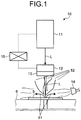
- FIG. 1 is a view schematically illustrating a laser processing apparatus in accordance with a first embodiment.
- a laser processing apparatus 10 according to a first embodiment is an apparatus capable of irradiating a composite material 5 to be processed with a laser L to perform hole processing on the composite material 5.
- Examples of the composite material 5 include fiber reinforced plastics such as carbon fiber reinforced plastics (CFRP), glass fiber reinforced plastics (GFRP), and glass mat reinforced thermoplastics (GMT).
- fiber reinforced plastics such as carbon fiber reinforced plastics (CFRP), glass fiber reinforced plastics (GFRP), and glass mat reinforced thermoplastics (GMT).
- the laser processing apparatus 10 includes a laser oscillator 11, a scanning optical system 12, a condensing optical system 13, a support base 6, a gas nozzle 14, and a controller 15.
- the laser oscillator 11 is an apparatus that outputs the laser L.
- the laser oscillator 11 used in the first embodiment uses a pulse oscillation (pulsed operation) system, and is an ultrashort pulse laser that outputs the ultrashort pulse laser L.
- the ultrashort pulse laser has a pulse width that ranges from several picoseconds to several femtoseconds.
- the first embodiment will be described with application of an ultrashort pulse laser, but a short pulse laser may be applied.
- the short pulse laser has a pulse width of several nanoseconds, 100 nanoseconds, or 10 microseconds.
- the scanning optical system 12 is an optical system that causes the laser L emitted from the laser oscillator 11 to scan on the composite material 5.
- the scanning optical system 12 includes a scanner that can operate the laser on the surface of the composite material 5.
- a prism rotor for rotating a prism or a galvanometer mirror is used, for example.
- the condensing optical system 13 is an optical system that condenses the laser L emitted from the scanning optical system 12 and irradiates the composite material 5 with the condensed laser L.
- the condensing optical system 13 includes optical elements such as a condenser lens.
- the support base 6 supports the composite material 5 at a predetermined position.
- the support base 6 may be a moving stage that causes the composite material 5 to be moved on a horizontal plane. With the laser L emitted from the laser oscillator 11, a surface of the composite material 5 arranged on the support base 6 is irradiated almost vertically.
- the gas nozzle 14 sprays inactive assist gas toward a surface of the composite material 5.
- a spraying direction of assist gas is a lateral direction intersecting an irradiation direction of the laser L, and is a direction along with a surface of the composite material 5.
- a suction aperture for sucking assist gas which is not illustrated, is provided to a side opposite to the gas nozzle 14 across the composite material 5.
- the controller 15 is connected to each of the units including the laser oscillator 11 and the scanning optical system 12, and controls each of the units to control operations of the laser processing apparatus 10. For example, the controller 15 controls the laser oscillator 11 to adjust irradiation conditions of the laser L emitted from the laser oscillator 11. For example, the controller 15 controls the scanning optical system 12 to control scanning operations of the laser L on a surface of the composite material 5.
- the laser oscillator 11 emits the laser L, and the emitted laser L is guided to the scanning optical system 12.
- the laser processing apparatus 10 causes the laser L having entered the scanning optical system 12 to scan to vary an irradiation position of the laser L on a surface of the composite material 5.
- the laser processing apparatus 10 causes the laser L emitted from the scanning optical system 12 to enter the condensing optical system 13, and irradiates the composite material 5 with the condensed laser L.
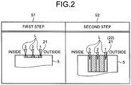
- FIG. 2 is an explanatory view related to processing conditions of the laser processing method in accordance with the first embodiment.
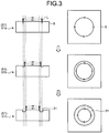
- FIG. 3 is an explanatory view related to a first step of the laser processing method in accordance with the first embodiment.
- FIG. 4 is an explanatory view related to a second step of the laser processing method in accordance with the first embodiment.
- the composite material 5 has, for example, a sheet thickness of 10 mm or more.
- the laser processing method includes a first step S1 for irradiating a surface of the composite material 5 with the laser L and forming a hole processing groove 21 in the composite material 5, and a second step S2 for irradiating and penetrating through the hole processing groove 21 with the laser L to form a through hole 22.
- irradiation conditions of the laser L emitted from the laser oscillator 11 are the same irradiation conditions.
- the laser oscillator 11 emits the picosecond laser L on the irradiation conditions that, in the laser having a pulse width of 10 ps or less and a wavelength of 1,030 nm, pulse repetition frequency and the maximum pulse energy are defined as 100 to 500 kHz and as 2.0 mJ, respectively, and the average output ranges from 200 to 1,000 w.
- the hole processing groove 21 to be formed is made to be a groove having an annular shape on a surface of the composite material 5 as illustrated in FIGS. 2 and 3 .
- the hole processing groove 21 is penetrated through, and a core material inside the hole processing groove 21 is removed to form the through hole 22 into a columnar shape (straight shape) as illustrated in FIGS. 2 and 4 .
- FIG. 2 illustrates a cutting surface orthogonal to the peripheral direction of the hole processing groove 21 formed into an annular shape.
- one side of a radial direction of the hole processing groove 21 corresponds to the inside, and the other side of the radial direction of the hole processing groove 21 (right side in FIG. 2 ) corresponds to the outside.
- a surface on the outside of the hole processing groove 21 corresponds to an inner peripheral surface of the through hole 22.
- the hole processing groove 21 is processed so that the depth thereof is, for example, 0.5 mm.
- processing is laser processing in which a length in a depth direction is shorter than the length at the second step S2.
- the laser L which causes a smaller heat input amount for the composite material 5 per unit time than that at the second step S2 is emitted.
- a scanning speed (scan speed) of the laser L is made faster than that at the second step S2.
- irradiation conditions of the laser L are the same irradiation conditions at the first step S1 and the second step S2.
- a heat input amount for the composite material 5 can be made smaller as much as a scanning speed at the first step S1 is faster.
- the laser L is emitted.
- the laser L is emitted on 3 paths.
- the 3 paths are defined so that the pitch between the respective paths is the same interval.
- the laser L scans and is emitted so that the laser L is directed from the outside path corresponding to an inner peripheral surface side of the through hole 22 to the inside path corresponding to a center side of the through hole 22.
- the hole processing groove 21 is formed into an annular shape, and, at the first step S1, the laser L is revolved in a peripheral direction three times from the outside to the inside to form the hole processing groove 21.
- the laser L scans the outside of the hole processing groove 21 to be formed, in other words, an inner peripheral surface side of the through hole 22 to be formed on a peripheral direction for one revolution to perform irradiation of the first path (step S1a). Subsequently, after execution of the processing at the step S1a, the laser L scans the inside by a predetermined pitch from the first path and scans the inside of the first path in a peripheral direction for one revolution to perform irradiation of the second path (step S1b).
- the laser L scans the inside by a predetermined pitch from the second path and scans the inside of the second path, in other words, the inside of the hole processing groove 21 to be formed in a peripheral direction for one revolution to perform irradiation of the third path (step S1c).
- executing the processing at the first step S1 causes the hole processing groove 21 having a predetermined depth to be formed.
- scanning operations of the laser L may be set so that the scanning operations are concentrically performed on the first path to the third path, and may be set so that the scanning operations are spirally continued on the first path to the third path. Processing at the first step S1 may be repeated a predetermined number of times.
- the composite material 5 is irradiated with the laser L to generate spatters 51 and fumes 52.
- assist gas is sprayed from the gas nozzle 14 toward a surface of the composite material 5 and assist gas including the spatters 51 and the fumes 52 is sucked from a suction aperture, which is not illustrated. In this manner, at the first step S1, the spatters 51 and the fumes 52 are removed.
- the laser L which causes a larger heat input amount for the composite material 5 per unit time than that at the first step S1 is emitted.
- a scanning speed (scan speed) of the laser L is made slower than that at the first step S1.
- irradiation conditions of the laser L are the same irradiation conditions at the first step S1 and the second step S2.
- a heat input amount for the composite material 5 per unit time can be made larder as much as a scanning speed at the second step S2 is slower, and cutting efficiency can be improved.
- the laser L is emitted at the second step S2.
- the laser L is emitted on 3 paths similarly to the processing at the first step S1.
- the number of paths is the same as that at the first step S1, but the number of paths may be larger than that at the first step S1.
- the 3 paths are defined so that the pitch between the respective paths is the same interval.
- the laser L scans and is emitted so that the laser L is directed from the outside path corresponding to an inner peripheral surface side of the through hole 22 to the inside path corresponding to a center side of the through hole 22 similarly to the processing at the first step S1.
- the hole processing groove 21 is formed into an annular shape, and, even at the second step S2, the laser L is revolved in a peripheral direction three times from the outside to the inside to process and penetrate through the hole processing groove 21 in a depth direction.
- irradiation of the laser L is started from an inner peripheral surface corresponding to a product surface of the through hole 22 to be formed.
- the laser L scans the outside of the hole processing groove 21, in other words, an inner peripheral surface side of the through hole 22 to be formed in a peripheral direction for one revolution to perform irradiation of the first path (step S2a). Subsequently, after execution of the processing at the step S2a, the laser L scans the inside by a predetermined pitch from the first path and scans the inside of the first path in a peripheral direction for one revolution to perform irradiation of the second path (step S2b).
- the laser L scans the inside by a predetermined pitch from the second path and scans the inside of the second path, in other words, the inside of the hole processing groove 21 in a peripheral direction for one revolution to perform irradiation of the third path (step S2c).
- executing processing at the second step S2 causes further processing to be performed on the hole processing groove 21 in a depth direction.
- Processing at the second step S2 is repeated until the hole processing groove 21 is penetrated through in a depth direction.
- the composite material 5 is irradiated with the laser L to generate the spatters 51 and the fumes 52.
- assist gas is sprayed from the gas nozzle 14 toward a surface of the composite material 5 and assist gas including the spatters 51 and the fumes 52 is sucked from a suction aperture, which is not illustrated. Thus, the spatters 51 and the fumes 52 are removed.
- the hole processing groove 21 can be formed on a surface of the composite material 5 with a small heat input amount at the first step S1. Even when a thickness of a composite material is thick, a heat-affected layer can be prevented from being formed on a surface of the composite material 5. In addition, a heat input amount added to a surface of the composite material 5 can be made small. Thus, the spatters 51 and the fumes 52 can be prevented from being generated, and the spatters 51 and the fumes 52 can be prevented from being attached to a surface of the composite material 5.
- the hole processing groove 21 can be formed deeper along with an irradiation direction of the laser L.
- the through hole 22 formed by the laser L can be formed in a straight shape in an irradiation direction of the laser L.
- the laser L can be emitted with the number of paths equal to or more than that at the first step S1.
- a length of the hole processing groove 21 in a width direction can be prevented from being shorter than that at the first step S1.
- a heat input amount for the composite material 5 by laser irradiation at the first step S1 can be made smaller without changing irradiation conditions of the laser L at the first step S1 and the second step S2.
- the pitch between a plurality of respective paths at the first step S1 is the same interval.
- a groove depth of the hole processing groove 21 can be equalized.
- the bottom surface of the hole processing groove 21 can be smoothed.
- the pitch between a plurality of respective paths at the second step S2 is the same interval.
- a groove depth of the hole processing groove 21 can be equalized.
- irradiation of the laser L can be started from an inner peripheral surface of the through hole 22 corresponding to a product surface, thereby performing hole processing on the inner peripheral surface of the through hole 22 with high accuracy.
- the fumes 52 generated by irradiating the composite material 5 with the laser L enables the fumes 52 generated by irradiating the composite material 5 with the laser L to be made finer.
- the fumes 52 generated at the first step S1 are made finer and can easily float to reduce generation of the fumes 52 attached to the composite material 5.
- spraying assist gas toward the hole processing groove 21 at the first step S1 and the second step S2 enables the spatters 51 and the fumes 52 generated by irradiating the composite material 5 with the laser L to be removed with the assist gas.
- the spatters 51 and the fumes 52 attached to the composite material 5 can be prevented from being generated.
- a heat input amount for the composite material 5 is adjusted by making a scanning speed of the laser L faster at the first step S1 and making a scanning speed of the laser L slower at the second step S2, but this configuration is not limiting.
- Output of the laser L may be smaller at the first step S1 and output of the laser L may be larger at the second step S2 than the output of the laser at the first step S1.
- the heat input amount for the composite material 5 at the first step S1 and the second step S2 can be adjusted without changing the scanning speed of the laser L at the first step S1 and the second step S2. In this manner, if the configuration is the one in which a heat input amount for the composite material 5 is smaller at the first step and a heat input amount for the composite material 5 at the second step is larger than the heat input amount at the first step S1, any configuration may be applied.
- the through hole 22 is formed into a hollow columnar shape having a circular aperture, but the shape of the through hole 22 is not particularly limiting.
- the shape of an aperture may be polygonal, and any shape may be applied.
- FIG. 5 is an explanatory view related to processing conditions of the laser processing method in accordance with the second embodiment.
- processing at a third step S3 is executed after processing at the second step S2.
- the through hole 22 is irradiated with the laser L in which the pitch between the respective paths in a width direction is narrower than that at the second step S2.
- the laser L is emitted.
- the laser L is emitted on 5 paths.
- the five paths are defined so that the pitch between the respective paths is the same interval.
- a length of the five paths in a width direction is the same as that of the three paths in a width direction at the second step S2.
- the pitch between the respective paths at the third step S3 is narrower than the pitch at the second step S2.
- the laser L scans and is emitted so that the laser L is directed from an inner peripheral surface side of the through hole 22 to a center side of the through hole 22 similarly to the processing at the first step S1 and the second step S2.
- FIG. 5 illustrates that processing at the third step S3 is executed before a remaining core material is removed at the second step S2. Processing at the third step S3 may be executed after a core material is removed.
- the laser L scans an inner peripheral surface side of the through hole 22 in a peripheral direction for one revolution to perform irradiation of the first path. Subsequently, after irradiation of the first path, the laser L scans the inside by a predetermined pitch from the first path and scans the inside of the first path in a peripheral direction for one revolution to perform irradiation of the second path. Because irradiation of the laser L on the third path to the fifth path is the same as that on the second path, the explanation is omitted.
- assist gas is sprayed from the gas nozzle 14 toward a surface of the composite material 5 at the third step S3.
- executing processing at the third step S3 enables an inner peripheral surface of the through hole 22 to be smoothed in a penetration direction and hole processing to be performed on the through hole 22 with high accuracy.
- the number of paths is larger than that of the second step S2, but the number of paths is not particularly limited.
- the number of the paths may be any number.
- the number of paths may be the same as that at the second step S2.
- irradiation of the laser L may be started from an inner peripheral surface side of the through hole 22.
Landscapes
- Physics & Mathematics (AREA)
- Optics & Photonics (AREA)
- Engineering & Computer Science (AREA)
- Plasma & Fusion (AREA)
- Mechanical Engineering (AREA)
- Laser Beam Processing (AREA)
- Moulding By Coating Moulds (AREA)
- Shaping Of Tube Ends By Bending Or Straightening (AREA)
Abstract
Description
- The present invention relates to a laser processing method and a laser processing apparatus for irradiating a composite material with a laser and processing the composite material.
- Laser processing has high-energy density, is effective in shortening a processing time, and is expected to have the same effects on fiber reinforced plastic composite materials such as carbon fiber reinforced plastics (CFRP), glass fiber reinforced plastics (GFRP), and glass mat reinforced thermoplastics (GMT). There has been known a laser processing method of a composite material for executing a first step of irradiating a part to be processed of a composite material with a high output power laser beam on multiple paths in the form of multiple lines at a high sweep speed, and a second step of reducing a degree of the multiple lines when a processing depth increases sequentially along with the progress of the first step (for example, see Patent Literature 1).
- Patent Literature 1: Japanese Patent Application Laid-open No.
2016-107574 - In drilling processing of a composite material, a through hole in a straight shape with a small inclination on a wall surface of a processing hole may be formed. When the laser processing method of
Patent Literature 1 is applied in order to form a through hole in a composite material using a laser, a degree of multiple lines is reduced and a wall surface of a throughhole 50 has an inclination as illustrated inFIG. 6 . Thus, it is difficult to form the throughhole 50 into a straight shape. In other words, at the second step, a degree of multiple lines is reduced as compared with the degree at a first step, and a length of a radial direction of the through hole orthogonal to a depth direction of the through hole is narrower as a depth of the through hole is deeper. Thus, a through hole is formed into a tapered shape that is narrower toward a depth direction. In a composite material having a thick sheet thickness, this inclination is noticeable, and the inclination needs to be corrected by reaming and the like after laser processing, thereby extending a processing time. - In the laser processing method of
Patent Literature 1, a degree of multiple lines at the first step is larger than that at the second step, and spatters 51 after laser processing are increased on a surface by widening a cutting width, thereby causingmore spatters 51 and fumes (high-temperature gas formed by subliming a material to be processed with a laser) to be attached on a surface of a composite material. - An object of the present invention is to provide a laser processing method and a laser processing apparatus capable of reducing spatters on a surface of a composite material and performing processing with excellent characteristics in the aspect of processing quality such as a processed shape and a heat-affected layer.
- A laser processing method according to an aspect of the present invention is for performing hole processing in which a composite material is irradiated with a laser to form a through hole. The laser processing method includes a first step of irradiating a surface of the composite material with the laser to form a hole processing groove on the composite material in a manner of scanning a plurality of paths from an outside corresponding to an inner peripheral surface side of the through hole to be formed to an inside corresponding to a center side of the through hole, the plurality of paths being across a width direction of the hole processing groove; and a second step of irradiating and penetrating through the hole processing groove with the laser to form the through hole in a manner of scanning a plurality of paths from the outside to the inside after the first step, the plurality of paths being across the width direction of the hole processing groove. The laser used at the first step has a smaller heat input amount per unit time than the laser used at the second step.
- With this configuration, at the first step, a hole processing groove can be formed on a surface of a composite material with a reduced heat input amount per unit time. Thus, a heat-affected layer can be prevented from being formed on a surface of a composite material. In addition, a generation amount of fumes can be reduced and the fumes can be prevented from being attached to a surface of a composite material because a heat input amount per unit time added to the surface of the composite material can be made smaller. At the second step, by emitting a laser on a plurality of paths so that the laser is directed from the outside to the inside of a through hole, a hole processing groove can be formed deeper along with an irradiation direction of the laser. Thus, a through hole formed by a laser can be formed in a straight shape in an irradiation direction of the laser. When an aperture of a through hole is round, a plurality of paths may be concentrically arranged or may be spirally connected.
- Preferably, the number of paths of the laser at the second step is equal to or more than the number of paths of the laser at the first step.
- With this configuration, at the second step, a laser can be emitted with the number of paths equal to or more than the number of paths at the first step. Thus, a length of a hole processing groove in a width direction can be prevented from being shorter than the length at the first step.
- Preferably, a scan speed of the laser at the first step is faster than a scan speed of the laser at the second step.
- With this configuration, by making a scan speed of a laser faster than the scan speed at the second step, a heat input amount for a composite material by laser irradiation at the first step can be made smaller without changing irradiation conditions at the first step and the second step. It is preferable that a scan speed at the first step be made faster, more than double a scan speed at the second step.
- Preferably, output of the laser at the first step is smaller than output of the laser at the second step.
- With this configuration, by making output of a laser smaller than output at the second step, a heat input amount per unit time by laser irradiation at the first step of a composite material can be made smaller without changing a scan speed of the laser at the first step and the second step.
- Preferably, at the first step and the second step, the plurality of paths include three paths or more, and pitches between the plurality of paths are the same in the width direction.
- With this configuration, the pitch between a plurality of respective paths at the first step is the same interval to equalize a groove depth of a hole processing groove. Similarly, the pitch between a plurality of respective paths at the second step is the same interval to equalize a groove depth of a hole processing groove.
- Preferably, irradiation of the laser is started from the inner peripheral surface corresponding to a product surface of the through hole at the second step.
- With this configuration, hole processing can be performed on an inner peripheral surface of a through hole corresponding to a product surface with high accuracy.
- Preferably, the laser is an ultrashort pulse laser or a short pulse laser.
- Processing using a laser serving as a continuous wave (CW) is basically heat processing, and generating spatters depending on a heat input amount is inevitable. However, if an ultrashort pulse laser or a short pulse laser is used as a laser, a pulse width is shortened, and processing can be non-heat processing to reduce a generation amount of spatters and fumes. Thus, irradiating a composite material with a laser enables generated spatters to be reduced and fumes to be decreased. Fine fumes generated at the first step easily float to reduce attachment to a composite material. An ultrashort pulse laser is a laser oscillator referred to as a picosecond laser and a femtosecond laser, and a pulse width thereof indicates a nanosecond or less. A short pulse laser means that a pulse width thereof ranges from a nanosecond to a microsecond. For example, a picosecond laser has a pulse interval of 10 picoseconds and 800 picoseconds, and a femtosecond laser has a pulse interval of 100 femtoseconds and 900 femtoseconds. A short pulse laser is a laser having a pulse interval of several nanoseconds, 100 nanoseconds, or 10 microseconds.
- Preferably, the first step includes spraying assist gas toward the hole processing groove to be formed, from a lateral direction intersecting an irradiation direction of the laser.
- With this configuration, by spraying assist gas using a gas nozzle from a lateral direction of a base material to be processed in order to remove spatters generated upon laser irradiation, fumes generated by irradiating a composite material with a laser can be forcibly removed by the assist gas. Thus, at the first step, fumes attached to a composite material can be prevented from being generated. At the second step, assist gas may be also sprayed onto a composite material.
- Preferably, the method further includes a third step of irradiating, after the second step, the through hole with the laser in a manner of scanning a plurality of paths having a narrower pitch than a pitch between the plurality of paths in the width direction at the second step.
- With this configuration, hole processing can be performed on an inner peripheral surface of a through hole with high accuracy. At the third step, the number of paths of a laser may be increased and may be the same number as much as the pitch is made narrower. When the number of paths of a laser is the same number, irradiation of a laser may be started from an inner peripheral surface side of a through hole.
- A laser processing apparatus according to another aspect of the present invention performs hole processing in which a composite material is irradiated with a laser to form a through hole. The laser processing apparatus includes a laser irradiating unit configured to irradiate a surface of the composite material with an ultrashort pulse laser or a short pulse laser as the laser; a laser scanner configured to cause the laser to scan; a gas nozzle configured to spray assist gas toward a surface of the composite material and spray assist gas in a lateral direction intersecting an irradiation direction of the laser; and a controller configured to control operations of the laser irradiating unit and the laser scanner.
- With this configuration, by irradiating a composite material with an ultrashort pulse laser or a short pulse laser, generated fumes can be made finer than fumes using a CW laser. At this time, by spraying assist gas toward a surface of a composite material, fine fumes can be blown away and the fumes can be prevented from being attached to the surface of the composite material.
- Preferably, the controller executes a first step of irradiating a surface of the composite material with the laser to form a hole processing groove on the composite material in a manner of scanning a plurality of paths from an outside corresponding to an inner peripheral surface side of the through hole to be formed to an inside corresponding to a center side of the through hole, the plurality of paths being across a width direction of the hole processing groove; and a second step of irradiating and penetrating through the hole processing groove with the laser to form the through hole in a manner of scanning a plurality of paths from the outside to the inside after the first step, the plurality of paths being across the width direction of the hole processing groove. The laser used at the first step has a smaller heat input amount per unit time than the laser used at the second step.
- With this configuration, at the first step, a hole processing groove can be formed on a surface of a composite material with a reduced heat input amount per unit time. Thus, a heat-affected layer can be prevented from being formed on a surface of a composite material, and spatters and fumes can be prevented from being attached to the surface. At the second step, by emitting a laser on a plurality of paths so that the laser is directed from the outside to the inside of a through hole, a hole processing groove can be cut off along with an irradiation direction of the laser. Thus, a through hole formed by a laser can be formed in a straight shape in an irradiation direction of the laser.
-
-
FIG. 1 is a view schematically illustrating a laser processing apparatus in accordance with a first embodiment. -
FIG. 2 is an explanatory view related to processing conditions of a laser processing method in accordance with the first embodiment. -
FIG. 3 is an explanatory view related to a first step of the laser processing method in accordance with the first embodiment. -
FIG. 4 is an explanatory view related to a second step of the laser processing method in accordance with the first embodiment. -
FIG. 5 is an explanatory view related to processing conditions of the laser processing method in accordance with a second embodiment. -
FIG. 6 is a cross-sectional view of a through hole formed by a laser processing method in accordance with a conventional way. - Embodiments according to the present invention will now be described in detail with reference to the accompanying drawings. It should be noted that the embodiments are not intended to limit this invention. Components in the following embodiments include components that can be replaced and are facilitated by the skilled person or substantially like components. Components described below can be combined as appropriate. When there are a plurality of the embodiments, each of the embodiments can be combined.
-
FIG. 1 is a view schematically illustrating a laser processing apparatus in accordance with a first embodiment. As illustrated inFIG. 1 , alaser processing apparatus 10 according to a first embodiment is an apparatus capable of irradiating acomposite material 5 to be processed with a laser L to perform hole processing on thecomposite material 5. - Examples of the
composite material 5 include fiber reinforced plastics such as carbon fiber reinforced plastics (CFRP), glass fiber reinforced plastics (GFRP), and glass mat reinforced thermoplastics (GMT). - As illustrated in
FIG. 1 , thelaser processing apparatus 10 includes alaser oscillator 11, a scanningoptical system 12, a condensingoptical system 13, asupport base 6, agas nozzle 14, and acontroller 15. - The
laser oscillator 11 is an apparatus that outputs the laser L. Thelaser oscillator 11 used in the first embodiment uses a pulse oscillation (pulsed operation) system, and is an ultrashort pulse laser that outputs the ultrashort pulse laser L. The ultrashort pulse laser has a pulse width that ranges from several picoseconds to several femtoseconds. The first embodiment will be described with application of an ultrashort pulse laser, but a short pulse laser may be applied. The short pulse laser has a pulse width of several nanoseconds, 100 nanoseconds, or 10 microseconds. - The scanning
optical system 12 is an optical system that causes the laser L emitted from thelaser oscillator 11 to scan on thecomposite material 5. The scanningoptical system 12 includes a scanner that can operate the laser on the surface of thecomposite material 5. As a scanner, a prism rotor for rotating a prism or a galvanometer mirror is used, for example. - The condensing
optical system 13 is an optical system that condenses the laser L emitted from the scanningoptical system 12 and irradiates thecomposite material 5 with the condensed laser L. The condensingoptical system 13 includes optical elements such as a condenser lens. - The
support base 6 supports thecomposite material 5 at a predetermined position. Thesupport base 6 may be a moving stage that causes thecomposite material 5 to be moved on a horizontal plane. With the laser L emitted from thelaser oscillator 11, a surface of thecomposite material 5 arranged on thesupport base 6 is irradiated almost vertically. - The
gas nozzle 14 sprays inactive assist gas toward a surface of thecomposite material 5. A spraying direction of assist gas is a lateral direction intersecting an irradiation direction of the laser L, and is a direction along with a surface of thecomposite material 5. A suction aperture for sucking assist gas, which is not illustrated, is provided to a side opposite to thegas nozzle 14 across thecomposite material 5. - The
controller 15 is connected to each of the units including thelaser oscillator 11 and the scanningoptical system 12, and controls each of the units to control operations of thelaser processing apparatus 10. For example, thecontroller 15 controls thelaser oscillator 11 to adjust irradiation conditions of the laser L emitted from thelaser oscillator 11. For example, thecontroller 15 controls the scanningoptical system 12 to control scanning operations of the laser L on a surface of thecomposite material 5. - In the
laser processing apparatus 10 formed as above, thelaser oscillator 11 emits the laser L, and the emitted laser L is guided to the scanningoptical system 12. Thelaser processing apparatus 10 causes the laser L having entered the scanningoptical system 12 to scan to vary an irradiation position of the laser L on a surface of thecomposite material 5. Thelaser processing apparatus 10 causes the laser L emitted from the scanningoptical system 12 to enter the condensingoptical system 13, and irradiates thecomposite material 5 with the condensed laser L. - With reference to
FIGS. 2 to 4 , using the abovelaser processing apparatus 10, a laser processing method for performing hole processing of a through hole on thecomposite material 5 will be described.FIG. 2 is an explanatory view related to processing conditions of the laser processing method in accordance with the first embodiment.FIG. 3 is an explanatory view related to a first step of the laser processing method in accordance with the first embodiment.FIG. 4 is an explanatory view related to a second step of the laser processing method in accordance with the first embodiment. Thecomposite material 5 has, for example, a sheet thickness of 10 mm or more. - The laser processing method includes a first step S1 for irradiating a surface of the
composite material 5 with the laser L and forming ahole processing groove 21 in thecomposite material 5, and a second step S2 for irradiating and penetrating through thehole processing groove 21 with the laser L to form a throughhole 22. At the first step S1 and the second step S2, irradiation conditions of the laser L emitted from thelaser oscillator 11 are the same irradiation conditions. As a specific example, in the laser processing method of the first embodiment, thelaser oscillator 11 emits the picosecond laser L on the irradiation conditions that, in the laser having a pulse width of 10 ps or less and a wavelength of 1,030 nm, pulse repetition frequency and the maximum pulse energy are defined as 100 to 500 kHz and as 2.0 mJ, respectively, and the average output ranges from 200 to 1,000 w. - When the through
hole 22 is formed by laser processing, at the first step S1, thehole processing groove 21 to be formed is made to be a groove having an annular shape on a surface of thecomposite material 5 as illustrated inFIGS. 2 and3 . At the second step S2, thehole processing groove 21 is penetrated through, and a core material inside thehole processing groove 21 is removed to form the throughhole 22 into a columnar shape (straight shape) as illustrated inFIGS. 2 and4 . -
FIG. 2 illustrates a cutting surface orthogonal to the peripheral direction of thehole processing groove 21 formed into an annular shape. InFIG. 2 , one side of a radial direction of the hole processing groove 21 (left side inFIG. 2 ) corresponds to the inside, and the other side of the radial direction of the hole processing groove 21 (right side inFIG. 2 ) corresponds to the outside. A surface on the outside of thehole processing groove 21 corresponds to an inner peripheral surface of the throughhole 22. At the first step, thehole processing groove 21 is processed so that the depth thereof is, for example, 0.5 mm. In other words, at the first step S1, processing is laser processing in which a length in a depth direction is shorter than the length at the second step S2. - At the first step S1, the laser L which causes a smaller heat input amount for the
composite material 5 per unit time than that at the second step S2 is emitted. Specifically, at the first step S1, a scanning speed (scan speed) of the laser L is made faster than that at the second step S2. In this case, irradiation conditions of the laser L are the same irradiation conditions at the first step S1 and the second step S2. Thus, a heat input amount for thecomposite material 5 can be made smaller as much as a scanning speed at the first step S1 is faster. - As illustrated in
FIG. 2 , at the first step S1, on a plurality of paths aligned in a width direction (radial direction) of thehole processing groove 21, the laser L is emitted. In the first embodiment, for example, the laser L is emitted on 3 paths. The 3 paths are defined so that the pitch between the respective paths is the same interval. At the first step S1, the laser L scans and is emitted so that the laser L is directed from the outside path corresponding to an inner peripheral surface side of the throughhole 22 to the inside path corresponding to a center side of the throughhole 22. In other words, thehole processing groove 21 is formed into an annular shape, and, at the first step S1, the laser L is revolved in a peripheral direction three times from the outside to the inside to form thehole processing groove 21. - As illustrated in
FIG. 3 , at the first step S1, the laser L scans the outside of thehole processing groove 21 to be formed, in other words, an inner peripheral surface side of the throughhole 22 to be formed on a peripheral direction for one revolution to perform irradiation of the first path (step S1a). Subsequently, after execution of the processing at the step S1a, the laser L scans the inside by a predetermined pitch from the first path and scans the inside of the first path in a peripheral direction for one revolution to perform irradiation of the second path (step S1b). Furthermore, after execution of the processing at the step S1b, the laser L scans the inside by a predetermined pitch from the second path and scans the inside of the second path, in other words, the inside of thehole processing groove 21 to be formed in a peripheral direction for one revolution to perform irradiation of the third path (step S1c). In this manner, executing the processing at the first step S1 causes thehole processing groove 21 having a predetermined depth to be formed. In this case, when the laser L is emitted on the first path to the third path, scanning operations of the laser L may be set so that the scanning operations are concentrically performed on the first path to the third path, and may be set so that the scanning operations are spirally continued on the first path to the third path. Processing at the first step S1 may be repeated a predetermined number of times. - At the first step S1, the
composite material 5 is irradiated with the laser L to generatespatters 51 and fumes 52. At the first step S1, upon processing thehole processing groove 21 by the laser L, assist gas is sprayed from thegas nozzle 14 toward a surface of thecomposite material 5 and assist gas including thespatters 51 and thefumes 52 is sucked from a suction aperture, which is not illustrated. In this manner, at the first step S1, thespatters 51 and thefumes 52 are removed. - At the second step S2, the laser L which causes a larger heat input amount for the
composite material 5 per unit time than that at the first step S1 is emitted. Specifically, at the second step S2, a scanning speed (scan speed) of the laser L is made slower than that at the first step S1. In this case, irradiation conditions of the laser L are the same irradiation conditions at the first step S1 and the second step S2. Thus, a heat input amount for thecomposite material 5 per unit time can be made larder as much as a scanning speed at the second step S2 is slower, and cutting efficiency can be improved. - As illustrated in
FIG. 2 , at the second step S2, on a plurality of paths aligned in a width direction (radial direction) of thehole processing groove 21, the laser L is emitted. In the first embodiment, for example, the laser L is emitted on 3 paths similarly to the processing at the first step S1. At the second step S2, the number of paths is the same as that at the first step S1, but the number of paths may be larger than that at the first step S1. The 3 paths are defined so that the pitch between the respective paths is the same interval. At the second step S2, the laser L scans and is emitted so that the laser L is directed from the outside path corresponding to an inner peripheral surface side of the throughhole 22 to the inside path corresponding to a center side of the throughhole 22 similarly to the processing at the first step S1. In other words, thehole processing groove 21 is formed into an annular shape, and, even at the second step S2, the laser L is revolved in a peripheral direction three times from the outside to the inside to process and penetrate through thehole processing groove 21 in a depth direction. In this case, at the second step S2, irradiation of the laser L is started from an inner peripheral surface corresponding to a product surface of the throughhole 22 to be formed. - As illustrated in
FIG. 4 , at the second step S2, the laser L scans the outside of thehole processing groove 21, in other words, an inner peripheral surface side of the throughhole 22 to be formed in a peripheral direction for one revolution to perform irradiation of the first path (step S2a). Subsequently, after execution of the processing at the step S2a, the laser L scans the inside by a predetermined pitch from the first path and scans the inside of the first path in a peripheral direction for one revolution to perform irradiation of the second path (step S2b). Furthermore, after execution of the processing at the step S2b, the laser L scans the inside by a predetermined pitch from the second path and scans the inside of the second path, in other words, the inside of thehole processing groove 21 in a peripheral direction for one revolution to perform irradiation of the third path (step S2c). In this manner, executing processing at the second step S2 causes further processing to be performed on thehole processing groove 21 in a depth direction. Processing at the second step S2 is repeated until thehole processing groove 21 is penetrated through in a depth direction. - Even at the second step S2, the
composite material 5 is irradiated with the laser L to generate thespatters 51 and thefumes 52. At the second step S2, similarly to the processing at the first step S1, upon hole processing by the laser L, assist gas is sprayed from thegas nozzle 14 toward a surface of thecomposite material 5 and assist gas including thespatters 51 and thefumes 52 is sucked from a suction aperture, which is not illustrated. Thus, thespatters 51 and thefumes 52 are removed. - When the
hole processing groove 21 is penetrated through in a depth direction by emitting the laser L, a columnar core material remains inside thehole processing groove 21, and the remaining core material is removed to form the throughhole 22 having a columnar shape. - As above, according to the first embodiment, the
hole processing groove 21 can be formed on a surface of thecomposite material 5 with a small heat input amount at the first step S1. Even when a thickness of a composite material is thick, a heat-affected layer can be prevented from being formed on a surface of thecomposite material 5. In addition, a heat input amount added to a surface of thecomposite material 5 can be made small. Thus, thespatters 51 and thefumes 52 can be prevented from being generated, and thespatters 51 and thefumes 52 can be prevented from being attached to a surface of thecomposite material 5. At the second step S2, by emitting the laser L on a plurality of paths so that the laser L is directed from the outside to the inside of the throughhole 22, thehole processing groove 21 can be formed deeper along with an irradiation direction of the laser L. Thus, the throughhole 22 formed by the laser L can be formed in a straight shape in an irradiation direction of the laser L. - According to the first embodiment, at the second step S2, the laser L can be emitted with the number of paths equal to or more than that at the first step S1. Thus, a length of the
hole processing groove 21 in a width direction can be prevented from being shorter than that at the first step S1. - According to the first embodiment, by making a scanning speed of the laser L faster than that at the second step S2, a heat input amount for the
composite material 5 by laser irradiation at the first step S1 can be made smaller without changing irradiation conditions of the laser L at the first step S1 and the second step S2. - According to the first embodiment, the pitch between a plurality of respective paths at the first step S1 is the same interval. Thus, a groove depth of the
hole processing groove 21 can be equalized. In other words, the bottom surface of thehole processing groove 21 can be smoothed. Similarly, the pitch between a plurality of respective paths at the second step S2 is the same interval. Thus, a groove depth of thehole processing groove 21 can be equalized. - According to the first embodiment, at the second step S2, irradiation of the laser L can be started from an inner peripheral surface of the through
hole 22 corresponding to a product surface, thereby performing hole processing on the inner peripheral surface of the throughhole 22 with high accuracy. - According to the first embodiment, using an ultrashort pulse laser as the laser L enables the
fumes 52 generated by irradiating thecomposite material 5 with the laser L to be made finer. Thus, thefumes 52 generated at the first step S1 are made finer and can easily float to reduce generation of thefumes 52 attached to thecomposite material 5. - According to the first embodiment, spraying assist gas toward the
hole processing groove 21 at the first step S1 and the second step S2 enables thespatters 51 and thefumes 52 generated by irradiating thecomposite material 5 with the laser L to be removed with the assist gas. Thus, at the first step S1, thespatters 51 and thefumes 52 attached to thecomposite material 5 can be prevented from being generated. - In the first embodiment, 3 paths are used at the first step S1 and the second step S2, but this is not particularly limiting, as long as the number of paths is plural. A heat input amount for the
composite material 5 is adjusted by making a scanning speed of the laser L faster at the first step S1 and making a scanning speed of the laser L slower at the second step S2, but this configuration is not limiting. Output of the laser L may be smaller at the first step S1 and output of the laser L may be larger at the second step S2 than the output of the laser at the first step S1. In this case, the heat input amount for thecomposite material 5 at the first step S1 and the second step S2 can be adjusted without changing the scanning speed of the laser L at the first step S1 and the second step S2. In this manner, if the configuration is the one in which a heat input amount for thecomposite material 5 is smaller at the first step and a heat input amount for thecomposite material 5 at the second step is larger than the heat input amount at the first step S1, any configuration may be applied. - According to the first embodiment, the through
hole 22 is formed into a hollow columnar shape having a circular aperture, but the shape of the throughhole 22 is not particularly limiting. For example, the shape of an aperture may be polygonal, and any shape may be applied. - A laser processing method according to a second embodiment will now be described with reference to
FIG. 5 . In the second embodiment, in order to avoid overlapped description, a part different from that of the first embodiment is described, and like reference signs are given to components having the same configuration as that of the first embodiment.FIG. 5 is an explanatory view related to processing conditions of the laser processing method in accordance with the second embodiment. - In the laser processing method of the second embodiment, processing at a third step S3 is executed after processing at the second step S2. At the third step S3, the through
hole 22 is irradiated with the laser L in which the pitch between the respective paths in a width direction is narrower than that at the second step S2. - As illustrated in
FIG. 5 , at the third step S3, on a plurality of paths aligned in a radial direction of the through hole 22 (width direction of thehole processing groove 21 before penetration), the laser L is emitted. In the second embodiment, for example, the laser L is emitted on 5 paths. The five paths are defined so that the pitch between the respective paths is the same interval. In this case, a length of the five paths in a width direction is the same as that of the three paths in a width direction at the second step S2. Thus, as much as the number of paths at the third step S3 is larger than the number of paths at the second step S2, the pitch between the respective paths at the third step S3 is narrower than the pitch at the second step S2. Even at the third step S3, the laser L scans and is emitted so that the laser L is directed from an inner peripheral surface side of the throughhole 22 to a center side of the throughhole 22 similarly to the processing at the first step S1 and the second step S2. -
FIG. 5 illustrates that processing at the third step S3 is executed before a remaining core material is removed at the second step S2. Processing at the third step S3 may be executed after a core material is removed. At the third step S3, the laser L scans an inner peripheral surface side of the throughhole 22 in a peripheral direction for one revolution to perform irradiation of the first path. Subsequently, after irradiation of the first path, the laser L scans the inside by a predetermined pitch from the first path and scans the inside of the first path in a peripheral direction for one revolution to perform irradiation of the second path. Because irradiation of the laser L on the third path to the fifth path is the same as that on the second path, the explanation is omitted. In this manner, at the third step S3, by irradiating the through hole with the laser L on a plurality of paths having a narrower pitch than that at the second step S2, an inner peripheral surface of the throughhole 22 can be smoothed in a penetration direction thereof. - Similarly to the processing at the first step S1 and the second step S2, assist gas is sprayed from the
gas nozzle 14 toward a surface of thecomposite material 5 at the third step S3. - As above, according to the second embodiment, executing processing at the third step S3 enables an inner peripheral surface of the through
hole 22 to be smoothed in a penetration direction and hole processing to be performed on the throughhole 22 with high accuracy. - In the second embodiment, at the third step S3, the number of paths is larger than that of the second step S2, but the number of paths is not particularly limited. At the third step S3, if the pitch between the respective paths is narrower than that at the second step S2, the number of the paths may be any number. For example, the number of paths may be the same as that at the second step S2. When the number of paths at the third step S3 is the same as that at the second step S2, irradiation of the laser L may be started from an inner peripheral surface side of the through
hole 22. -
- 5
- Composite material
- 6
- Support base
- 10
- Laser processing apparatus
- 11
- Laser oscillator
- 12
- Scanning optical system
- 13
- Condensing optical system
- 14
- Gas nozzle
- 15
- Controller
- 21
- Hole processing groove
- 22
- Through hole
- L
- Laser
Claims (11)
- A laser processing method for performing hole processing in which a composite material is irradiated with a laser to form a through hole, the laser processing method comprising:a first step of irradiating a surface of the composite material with the laser to form a hole processing groove on the composite material in a manner of scanning a plurality of paths from an outside corresponding to an inner peripheral surface side of the through hole to be formed to an inside corresponding to a center side of the through hole, the plurality of paths being across a width direction of the hole processing groove; anda second step of irradiating and penetrating through the hole processing groove with the laser to form the through hole in a manner of scanning a plurality of paths from the outside to the inside after the first step, the plurality of paths being across the width direction of the hole processing groove, whereinthe laser used at the first step has a smaller heat input amount per unit time than the laser used at the second step.
- The laser processing method according to claim 1, wherein the number of paths of the laser at the second step is equal to or more than the number of paths of the laser at the first step.
- The laser processing method according to claim 1 or 2, wherein a scan speed of the laser at the first step is faster than a scan speed of the laser at the second step.
- The laser processing method according to claim 1 or 2, wherein output of the laser at the first step is smaller than output of the laser at the second step.
- The laser processing method according to any one of claims 1 to 4, wherein at the first step and the second step, the plurality of paths include three paths or more, and pitches between the plurality of paths are the same in the width direction.
- The laser processing method according to any one of claims 1 to 5, wherein irradiation of the laser is started from the inner peripheral surface corresponding to a product surface of the through hole at the second step.
- The laser processing method according to any one of claims 1 to 6, wherein the laser is an ultrashort pulse laser or a short pulse laser.
- The laser processing method according to any one of claims 1 to 7, wherein the first step includes spraying assist gas toward the hole processing groove to be formed, from a lateral direction intersecting an irradiation direction of the laser.
- The laser processing method according to any one of claims 1 to 8, further comprising a third step of irradiating, after the second step, the through hole with the laser in a manner of scanning a plurality of paths having a narrower pitch than a pitch between the plurality of paths in the width direction at the second step.
- A laser processing apparatus that performs hole processing in which a composite material is irradiated with a laser to form a through hole, the laser processing apparatus comprising:a laser irradiating unit configured to irradiate a surface of the composite material with an ultrashort pulse laser or a short pulse laser as the laser;a laser scanner configured to cause the laser to scan;a gas nozzle configured to spray assist gas toward a surface of the composite material and spray assist gas in a lateral direction intersecting an irradiation direction of the laser; anda controller configured to control operations of the laser irradiating unit and the laser scanner.
- The laser processing apparatus according to claim 10, wherein the controller executes:a first step of irradiating a surface of the composite material with the laser to form a hole processing groove on the composite material in a manner of scanning a plurality of paths from an outside corresponding to an inner peripheral surface side of the through hole to be formed to an inside corresponding to a center side of the through hole, the plurality of paths being across a width direction of the hole processing groove; anda second step of irradiating and penetrating through the hole processing groove with the laser to form the through hole in a manner of scanning a plurality of paths from the outside to the inside after the first step, the plurality of paths being across the width direction of the hole processing groove, andthe laser used at the first step has a smaller heat input amount per unit time than the laser used at the second step.
Applications Claiming Priority (1)
| Application Number | Priority Date | Filing Date | Title |
|---|---|---|---|
| JP2019057450A JP7291510B2 (en) | 2019-03-25 | 2019-03-25 | Laser processing method |
Publications (1)
| Publication Number | Publication Date |
|---|---|
| EP3715037A1 true EP3715037A1 (en) | 2020-09-30 |
Family
ID=69570559
Family Applications (1)
| Application Number | Title | Priority Date | Filing Date |
|---|---|---|---|
| EP20156433.3A Pending EP3715037A1 (en) | 2019-03-25 | 2020-02-10 | Laser processing method and laser processing apparatus |
Country Status (4)
| Country | Link |
|---|---|
| US (1) | US11583957B2 (en) |
| EP (1) | EP3715037A1 (en) |
| JP (1) | JP7291510B2 (en) |
| CA (1) | CA3071681C (en) |
Families Citing this family (3)
| Publication number | Priority date | Publication date | Assignee | Title |
|---|---|---|---|---|
| KR102630873B1 (en) * | 2019-05-03 | 2024-01-31 | 삼성디스플레이 주식회사 | Manufacturing method for the window |
| JP7240774B2 (en) * | 2020-10-16 | 2023-03-16 | 国立大学法人信州大学 | Optical unit and laser processing equipment |
| CN114786340A (en) * | 2022-03-25 | 2022-07-22 | 武汉华工激光工程有限责任公司 | Blind hole processing method and FPC (flexible printed circuit) processing method |
Citations (4)
| Publication number | Priority date | Publication date | Assignee | Title |
|---|---|---|---|---|
| US20100282727A1 (en) * | 2008-01-17 | 2010-11-11 | Honda Motor Co., Ltd. | Laser working apparatus, and laser working method |
| JP2016107574A (en) | 2014-12-09 | 2016-06-20 | 国立研究開発法人産業技術総合研究所 | High-speed laser processing method for fiber reinforced composite material and high-speed laser processing apparatus for the same |
| US20170225271A1 (en) * | 2014-08-06 | 2017-08-10 | Bae Systems Plc | Substrate manufacture |
| US9950392B2 (en) * | 2014-03-04 | 2018-04-24 | Rohr, Inc. | Forming one or more apertures in a fiber-reinforced composite object with a laser |
Family Cites Families (8)
| Publication number | Priority date | Publication date | Assignee | Title |
|---|---|---|---|---|
| JPH0775787B2 (en) * | 1990-05-23 | 1995-08-16 | 新日本製鐵株式会社 | Laser drilling method for ceramics |
| JP2001269793A (en) * | 2000-03-27 | 2001-10-02 | Ricoh Microelectronics Co Ltd | Method of laser beam machining |
| DE10207288B4 (en) * | 2002-02-21 | 2005-05-04 | Newson Engineering Nv | Method for drilling holes by means of a laser beam in a substrate, in particular in an electrical circuit substrate |
| JP2004216385A (en) * | 2003-01-09 | 2004-08-05 | Hitachi Via Mechanics Ltd | Laser drilling method |
| US8716625B2 (en) * | 2012-02-03 | 2014-05-06 | Trumpf Werkzeugmaschinen Gmbh + Co. Kg | Workpiece cutting |
| DE102012219196B3 (en) * | 2012-10-22 | 2014-02-06 | Trumpf Werkzeugmaschinen Gmbh + Co. Kg | Method and machine for grooving, drilling or cutting metal workpieces |
| JP6804224B2 (en) | 2016-06-22 | 2020-12-23 | 三菱重工業株式会社 | Laser machining equipment and laser machining method |
| JP2018016525A (en) * | 2016-07-29 | 2018-02-01 | 三星ダイヤモンド工業株式会社 | Laser processing method and laser processing device for brittle material substrate |
-
2019
- 2019-03-25 JP JP2019057450A patent/JP7291510B2/en active Active
-
2020
- 2020-02-07 US US16/784,991 patent/US11583957B2/en active Active
- 2020-02-07 CA CA3071681A patent/CA3071681C/en active Active
- 2020-02-10 EP EP20156433.3A patent/EP3715037A1/en active Pending
Patent Citations (4)
| Publication number | Priority date | Publication date | Assignee | Title |
|---|---|---|---|---|
| US20100282727A1 (en) * | 2008-01-17 | 2010-11-11 | Honda Motor Co., Ltd. | Laser working apparatus, and laser working method |
| US9950392B2 (en) * | 2014-03-04 | 2018-04-24 | Rohr, Inc. | Forming one or more apertures in a fiber-reinforced composite object with a laser |
| US20170225271A1 (en) * | 2014-08-06 | 2017-08-10 | Bae Systems Plc | Substrate manufacture |
| JP2016107574A (en) | 2014-12-09 | 2016-06-20 | 国立研究開発法人産業技術総合研究所 | High-speed laser processing method for fiber reinforced composite material and high-speed laser processing apparatus for the same |
Also Published As
| Publication number | Publication date |
|---|---|
| CA3071681A1 (en) | 2020-09-25 |
| US11583957B2 (en) | 2023-02-21 |
| US20200306889A1 (en) | 2020-10-01 |
| JP2020157324A (en) | 2020-10-01 |
| CA3071681C (en) | 2022-05-31 |
| JP7291510B2 (en) | 2023-06-15 |
Similar Documents
| Publication | Publication Date | Title |
|---|---|---|
| US11583957B2 (en) | Laser processing method and laser processing apparatus | |
| JP6552503B2 (en) | Method of laser cutting a sapphire substrate by laser, and article comprising sapphire having an edge with a series of defects | |
| US12533746B2 (en) | Beam machining of workpieces | |
| JP5148717B2 (en) | Pulse laser processing apparatus and pulse laser processing method | |
| KR20120000073A (en) | Method for improved treatment of brittle materials | |
| US11548099B2 (en) | Laser processing method and laser processing apparatus | |
| JP2012512131A (en) | Method of laser processing glass into a shape with chamfered edges | |
| KR970013540A (en) | A laser processing method for a wiring board, a laser processing apparatus for a wiring board, and a carbon dioxide gas laser oscillator for processing a wiring board | |
| US20190255649A1 (en) | Laser beam machining method and laser beam machine | |
| JP5873978B2 (en) | Laser processing method and nozzle manufacturing method | |
| WO2015008482A1 (en) | Laser processing device, laser processing method, and laser oscillation device | |
| CN112192054A (en) | Laser processing method | |
| US20220258285A1 (en) | Laser cutting method and associated laser cutting device | |
| JP2013091074A (en) | Pulse laser machining apparatus, and pulse laser machining method | |
| JP2020109820A (en) | Laser processing method for printed circuit board and laser processing machine for printed circuit board | |
| CN113828932A (en) | Surface high-integrity micropore machining method and system based on laser hole making | |
| KR20140138456A (en) | Laser glass cutting system and method for cutting glass using the same | |
| KR101897337B1 (en) | Method and device for laser machining a substrate with multiple deflections of a laser radiation | |
| JP2013121605A (en) | Pulse laser machining apparatus and pulse laser machining method | |
| JP5197271B2 (en) | Laser processing apparatus and laser processing method | |
| CN115041815B (en) | Laser processing system and processing method for brittle materials | |
| JP2017104875A (en) | Laser processing apparatus and laser processing method | |
| JP2020157324A5 (en) | ||
| JP2018002501A (en) | Parting method of tubular brittle member, and parting device | |
| JP7290239B1 (en) | LASER CUTTING METHOD AND LASER CUTTING APPARATUS |
Legal Events
| Date | Code | Title | Description |
|---|---|---|---|
| PUAI | Public reference made under article 153(3) epc to a published international application that has entered the european phase |
Free format text: ORIGINAL CODE: 0009012 |
|
| STAA | Information on the status of an ep patent application or granted ep patent |
Free format text: STATUS: REQUEST FOR EXAMINATION WAS MADE |
|
| 17P | Request for examination filed |
Effective date: 20200210 |
|
| AK | Designated contracting states |
Kind code of ref document: A1 Designated state(s): AL AT BE BG CH CY CZ DE DK EE ES FI FR GB GR HR HU IE IS IT LI LT LU LV MC MK MT NL NO PL PT RO RS SE SI SK SM TR |
|
| AX | Request for extension of the european patent |
Extension state: BA ME |
|
| STAA | Information on the status of an ep patent application or granted ep patent |
Free format text: STATUS: EXAMINATION IS IN PROGRESS |
|
| 17Q | First examination report despatched |
Effective date: 20230714 |
|
| GRAP | Despatch of communication of intention to grant a patent |
Free format text: ORIGINAL CODE: EPIDOSNIGR1 |
|
| STAA | Information on the status of an ep patent application or granted ep patent |
Free format text: STATUS: GRANT OF PATENT IS INTENDED |
|
| INTG | Intention to grant announced |
Effective date: 20260401 |