EP3714972A1 - Reactor and method for operating a reactor - Google Patents
Reactor and method for operating a reactor Download PDFInfo
- Publication number
- EP3714972A1 EP3714972A1 EP19165861.6A EP19165861A EP3714972A1 EP 3714972 A1 EP3714972 A1 EP 3714972A1 EP 19165861 A EP19165861 A EP 19165861A EP 3714972 A1 EP3714972 A1 EP 3714972A1
- Authority
- EP
- European Patent Office
- Prior art keywords
- tubes
- reactor
- tube bundle
- bundle reactor
- closure device
- Prior art date
- Legal status (The legal status is an assumption and is not a legal conclusion. Google has not performed a legal analysis and makes no representation as to the accuracy of the status listed.)
- Withdrawn
Links
Images


Classifications
-
- B—PERFORMING OPERATIONS; TRANSPORTING
- B01—PHYSICAL OR CHEMICAL PROCESSES OR APPARATUS IN GENERAL
- B01J—CHEMICAL OR PHYSICAL PROCESSES, e.g. CATALYSIS OR COLLOID CHEMISTRY; THEIR RELEVANT APPARATUS
- B01J4/00—Feed or outlet devices; Feed or outlet control devices
- B01J4/008—Feed or outlet control devices
-
- B—PERFORMING OPERATIONS; TRANSPORTING
- B01—PHYSICAL OR CHEMICAL PROCESSES OR APPARATUS IN GENERAL
- B01J—CHEMICAL OR PHYSICAL PROCESSES, e.g. CATALYSIS OR COLLOID CHEMISTRY; THEIR RELEVANT APPARATUS
- B01J8/00—Chemical or physical processes in general, conducted in the presence of fluids and solid particles; Apparatus for such processes
- B01J8/02—Chemical or physical processes in general, conducted in the presence of fluids and solid particles; Apparatus for such processes with stationary particles, e.g. in fixed beds
- B01J8/06—Chemical or physical processes in general, conducted in the presence of fluids and solid particles; Apparatus for such processes with stationary particles, e.g. in fixed beds in tube reactors; the solid particles being arranged in tubes
-
- B—PERFORMING OPERATIONS; TRANSPORTING
- B01—PHYSICAL OR CHEMICAL PROCESSES OR APPARATUS IN GENERAL
- B01J—CHEMICAL OR PHYSICAL PROCESSES, e.g. CATALYSIS OR COLLOID CHEMISTRY; THEIR RELEVANT APPARATUS
- B01J2208/00—Processes carried out in the presence of solid particles; Reactors therefor
- B01J2208/00008—Controlling the process
- B01J2208/00017—Controlling the temperature
- B01J2208/00106—Controlling the temperature by indirect heat exchange
- B01J2208/00168—Controlling the temperature by indirect heat exchange with heat exchange elements outside the bed of solid particles
-
- B—PERFORMING OPERATIONS; TRANSPORTING
- B01—PHYSICAL OR CHEMICAL PROCESSES OR APPARATUS IN GENERAL
- B01J—CHEMICAL OR PHYSICAL PROCESSES, e.g. CATALYSIS OR COLLOID CHEMISTRY; THEIR RELEVANT APPARATUS
- B01J2208/00—Processes carried out in the presence of solid particles; Reactors therefor
- B01J2208/00008—Controlling the process
- B01J2208/00548—Flow
-
- B—PERFORMING OPERATIONS; TRANSPORTING
- B01—PHYSICAL OR CHEMICAL PROCESSES OR APPARATUS IN GENERAL
- B01J—CHEMICAL OR PHYSICAL PROCESSES, e.g. CATALYSIS OR COLLOID CHEMISTRY; THEIR RELEVANT APPARATUS
- B01J2208/00—Processes carried out in the presence of solid particles; Reactors therefor
- B01J2208/00008—Controlling the process
- B01J2208/00628—Controlling the composition of the reactive mixture
- B01J2208/00637—Means for stopping or slowing down the reaction
-
- B—PERFORMING OPERATIONS; TRANSPORTING
- B01—PHYSICAL OR CHEMICAL PROCESSES OR APPARATUS IN GENERAL
- B01J—CHEMICAL OR PHYSICAL PROCESSES, e.g. CATALYSIS OR COLLOID CHEMISTRY; THEIR RELEVANT APPARATUS
- B01J2208/00—Processes carried out in the presence of solid particles; Reactors therefor
- B01J2208/06—Details of tube reactors containing solid particles
-
- Y—GENERAL TAGGING OF NEW TECHNOLOGICAL DEVELOPMENTS; GENERAL TAGGING OF CROSS-SECTIONAL TECHNOLOGIES SPANNING OVER SEVERAL SECTIONS OF THE IPC; TECHNICAL SUBJECTS COVERED BY FORMER USPC CROSS-REFERENCE ART COLLECTIONS [XRACs] AND DIGESTS
- Y02—TECHNOLOGIES OR APPLICATIONS FOR MITIGATION OR ADAPTATION AGAINST CLIMATE CHANGE
- Y02E—REDUCTION OF GREENHOUSE GAS [GHG] EMISSIONS, RELATED TO ENERGY GENERATION, TRANSMISSION OR DISTRIBUTION
- Y02E60/00—Enabling technologies; Technologies with a potential or indirect contribution to GHG emissions mitigation
- Y02E60/30—Hydrogen technology
- Y02E60/36—Hydrogen production from non-carbon containing sources, e.g. by water electrolysis
-
- Y—GENERAL TAGGING OF NEW TECHNOLOGICAL DEVELOPMENTS; GENERAL TAGGING OF CROSS-SECTIONAL TECHNOLOGIES SPANNING OVER SEVERAL SECTIONS OF THE IPC; TECHNICAL SUBJECTS COVERED BY FORMER USPC CROSS-REFERENCE ART COLLECTIONS [XRACs] AND DIGESTS
- Y02—TECHNOLOGIES OR APPLICATIONS FOR MITIGATION OR ADAPTATION AGAINST CLIMATE CHANGE
- Y02P—CLIMATE CHANGE MITIGATION TECHNOLOGIES IN THE PRODUCTION OR PROCESSING OF GOODS
- Y02P20/00—Technologies relating to chemical industry
- Y02P20/10—Process efficiency
- Y02P20/133—Renewable energy sources, e.g. sunlight
Definitions
- the invention relates to a reactor and a method for operating a reactor for converting carbon dioxide and / or carbon monoxide and hydrogen to methanol.
- Fossil fuels cause carbon dioxide emissions that are not in line with global climate protection goals.
- regenerative energy sources generate electricity, which is not always available with the same output, i.e. it is subject to fluctuations. Attempts are currently being made to make sensible use of this available electrical, regeneratively generated electricity and, for example, to produce chemical products of value.
- One possibility is the electrochemical conversion of water into hydrogen and oxygen. The hydrogen produced can then react with carbon dioxide or carbon monoxide as a starter molecule, which at the same time reduces carbon dioxide emissions.
- the relatively easily available carbon dioxide, which should not be released into the atmosphere anyway, can thus be used as a cost-effective carbon source.
- methanol is a possible product of a one-step synthesis from carbon dioxide and hydrogen according to the following equation: CO 2 + 3H 2 -> CH 3 OH + H 2 O
- Today synthesis plants are mainly operated in continuous continuous operation. Typically, Quentsch reactors, adiabatic reactors, gas-cooled reactors, and isothermal boiling water reactors are used to carry out a methanol synthesis. What all these reactor models have in common is that they are designed for methanol synthesis in continuous operation with 8500 full load hours. Temperature fluctuations and pressure fluctuations should be avoided as completely as possible in order to maximize the service life of the catalytic converter.
- a catalyst change in large methanol plants disadvantageously leads to several weeks of operating failure and thus to considerable costs. If the methanol synthesis is operated with carbon dioxide and hydrogen from renewable energies, it can be assumed that the full load hours will be significantly reduced and the plant will be started up and shut down more frequently. The catalyst is then disadvantageously loaded. The catalyst ages faster, which significantly reduces the catalyst service life.
- the object is achieved according to the invention with a reactor according to claim 1 and a method according to claim 12.
- a tubular reactor according to the invention for converting carbon dioxide to methanol comprises at least two tubes and a gas distributor for distributing a gaseous starting material to the tubes.
- a catalyst is placed in the tubes. Individual pipes or groups of pipes have closure devices for closure.
- the method according to the invention for operating a tubular reactor for converting carbon dioxide to methanol comprises several steps. First, a reactor with at least two tubes and a gas distributor for distributing a gaseous starting material comprising hydrogen and carbon dioxide to the tubes is provided. Individual tubes or tube groups have a closing device for closing. The gaseous starting material is fed into the pipes. The reactor is operated here, with individual tubes or groups of tubes being closed when the amount of starting material decreases or individual tubes or groups of tubes being opened when the amount of starting material increases.
- the reactor represents a tube bundle reactor.
- Individual tubes or tube groups of this tube bundle reactor can advantageously be closed as required. This is particularly the case when little starting material, in particular hydrogen, is available for a reaction. If the amount of available educt increases again, these tubes or tube groups can advantageously be opened again. It is therefore advantageously possible to operate the reactor dynamically without having to shut it down completely. Individual pipes do not have to be operated at part load, which would damage the catalytic converter.
- the tubes are either completely closed or remain open for a reaction. The reaction continues in the opened tubes. The exothermic reaction generates heat. This heat is transferred to other pipes. In particular, it is also transferred to pipes that are closed. This advantageously ensures that the temperature in the tubes, in particular in the closed tubes, does not drop below the condensation temperature of the reaction products water and methanol.
- the closure device is arranged at the end of a pipe.
- the closure device is particularly advantageously arranged in such a way that the flow direction of the starting materials is towards the closure device.
- the switched-off pipes are therefore advantageously still filled with feed gas.
- the reaction then advantageously continues in these tubes until chemical equilibrium is reached. This also has the advantage that the temperature in the switched-off pipes drops slowly. This protects both the catalyst and the other materials used.
- the reactor comprises at least four tubes, at least one group of tubes being arranged on a circumference.
- the tube bundle reactor can in particular also comprise 50 tubes, particularly preferably 1000 tubes, or even more than 10,000 tubes. If the tubes lie in groups around one another in a circle, it is advantageously ensured that heat can be exchanged between the tubes. In the event that individual tubes or tube groups are closed, it can thus advantageously be ensured that surrounding open tubes in which the exothermic reaction takes place are kept at a temperature above the condensation temperature of water and methanol.
- Another advantage is that the number of tubes lying on a circumference increases from the center outwards.
- a different number of tubes can be closed, in other words switched off.
- a fluid in particular water
- the tubes are surrounded by the fluid.
- the water can advantageously influence the temperature in the tube bundle reactor.
- the water can store the heat so that the temperature in closed pipes is kept above the condensation temperature.
- the water on the other hand, can lower the temperature in the reactor. This is particularly useful when all tubes are open and a maximum temperature in the reactor should not be exceeded.
- the catalyst is then advantageously protected.
- Typical reaction conditions for the synthesis of methanol are temperatures in a range between 200 ° C and 300 ° C.
- the pressure is in a range from 50 bar to 100 bar.
- the closure device is designed as at least one perforated disk.
- the holes are arranged in groups on the circumference of the tubes.
- the diameter of the holes corresponds to a pipe diameter.
- the perforated disk can be arranged over a group of tubes arranged in a circle in such a way that the tubes of this group are closed as a whole or open as a whole. You can switch back and forth between these two positions by rotating the perforated disk, in particular around the center of the tube bundle reactor.
- Several perforated disks can be arranged one above the other.
- at least one ring with holes can be arranged around a first perforated disk, which ring has tubes on a second larger circumference. In this way, pipe groups that are arranged on different circumferences can be opened or closed independently of one another.
- the closure device comprises closure disks for closing individual tubes.
- These sealing disks have at least the pipe diameter.
- These closure disks are particularly preferred on one Ring attached.
- This ring has the same diameter as individual tube groups of the tube bundle reactor.
- the tubes of a tube group can be closed or opened on the same circumference by rotating the ring, in particular around the center of the tubular reactor.
- Several rings with locking disks can be arranged one above the other or one inside the other. The different rings then have different diameters. The diameters correspond to the circumference of the circle on which the tubes of the reactor are arranged. In this way, tube groups that are arranged on different circumferences can be opened or closed independently of one another.
- Both the perforated disks and the closure disks are expediently placed directly on the tubes so that they can be completely closed. If perforated disks are arranged one above the other, a difference in height between the disks could be compensated for by seals or by different pipe lengths, so that the perforated disks can close individual pipes. Alternatively or in addition, it is possible to arrange seals between the tubes and the perforated disk and / or the sealing disk.
- the seals include in particular graphite as materials, particularly preferred as carbon fiber materials and metal.
- a tube group that is closed is therefore preferably always adjacent to a tube group that is open. This ensures that the temperature in the pipes, which are closed and which cool down due to the lack of heat from the exothermic reaction, remains sufficiently high so that the condensation temperature does not fall below. As a result, it is also not necessary to design all the pipes so that they can be closed. A pipe group can always remain open. If the load in the reactor is no longer sufficient even for this minimum load in the pipes that are always open, the reactor should be shut down.
- the locking device has a magnetic coupling for moving the locking disks or perforated disks in a contactless manner.
- the locking disks or the perforated disks can be rotated from the outside by means of the magnetic coupling. This advantageously keeps the number of seals in contact with the media as low as possible.
- the closure device comprises valves for closing individual tubes.
- the valves should withstand the temperatures and pressures of the reaction, in particular pressures in the range from 50 bar to 100 bar and temperatures in a range from 200.degree. C. to 300.degree.
- the closure device comprises lids, the lids having different weights.
- the closing and opening of the tubes is determined by the flow in the tubes. If the flow in the pipes decreases because less educt, in particular hydrogen, is available, the flow pressure also decreases. Depending on the weights on the lids, the flow pressure is no longer sufficient to lift the lids and hold the pipe open.
- tubes can advantageously be opened or closed individually, regardless of their position in the reactor, that is to say also regardless of an arrangement on a circumference. Only covers of different weights are mounted. Particularly preferably, the covers comprise a closure disk on which different weights are attached. The covers are particularly preferably located at the end of the tube in the direction of flow.
- the closure device comprises springs, the springs having different spring strengths. They also have sealing disks, which have at least the diameter of the tubes, in order to close them.
- the springs are arranged in the direction of flow at the end of the tube. In other words, the reactant gas flows towards the springs.
- individual tubes or tube groups can advantageously be closed over the entire reactor, regardless of whether they are arranged on circumferences or not.
- the hydrogen is produced by means of water electrolysis from wind energy, solar energy and / or water energy. It is therefore advantageously possible by means of this invention to store the energy as a valuable material, in this case methanol, in times with a lot of sun and a lot of electricity. Since these renewable energies do not occur constantly, but dynamically as a function of the weather, it is advantageously possible to design the methanol synthesis dynamically with the reactor according to the invention and the method.
- the closing and opening takes place depending on the availability of hydrogen.
- Hydrogen in particular is obtained from renewable energies that are not always available.
- the availability of hydrogen from renewable energies determines whether the reactor has to be operated at full load or part load.
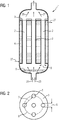
- Figure 1 shows a reactor 1 with three tubes 2 in a side view.
- the starting materials hydrogen 25 and carbon dioxide 26 flow in through the inlet of the reactor 1 and are distributed uniformly over the cross section of the reactor 1 in the gas distributor 9.
- the position of the perforated disk 3 is set in such a way that the tubes 2 remain open and thus products and unreacted starting materials can leave the reactor 1.
- a cooling medium, in this example water 27, is passed between the tubes in a cooling medium receiving space 4 and then passed out again.
- Figure 2 shows a top view of the perforated disk 3. It can be seen here that the holes 5 of the perforated disk are arranged on a circumference. This circumference corresponds to the circumference of the arrangement of the tubes in the tube bundle reactor 1. The diameter of the holes 5 corresponds at least to the diameter of the tubes 2. The hole spacing 7 of the holes 5 also corresponds to at least the diameter of the tubes 2. This makes it possible by rotating the perforated disk 3 and the resulting change in the position of the perforated disc to close tubes 2. In this example, by changing the position of the perforated disc, the tubes of the first circumference 8 would be closed. Only the inner tube of the reactor 1 would remain open.
- the reactor 1 can thus advantageously be operated at part load.
- the tubes lying on the first circumference 8 are heated by the waste heat of the open tube in the middle in which the exothermic reaction takes place.
- the temperature of the outer tubes therefore advantageously does not fall below the condensation temperature of water and methanol.
- the number of tubes is many times higher than shown here.
- the number of tubes here can be at least 10,000 tubes in a tube bundle reactor.
- FIG. 3 a reactor 1 with ten tubes 2 is shown. Three of the tubes 2 lie on an inner first circumference 8. Another seven Pipes lie on a second outer circumference 12.
- the closure device comprises closure disks 10. The diameter of the closure disks 10 have at least the diameter of the tubes 2.
- the closure disks 10, which lie on the first circular circumference 8, are connected to one another via a first ring 11.
- the closure disks 10, which lie on the second circumference 12, are connected to one another via a second ring 13.
- Figure 3 shows both rings in the position in which the tubes 2 of the reactor 1 are open. If the outer, second ring 13 is now rotated, the positions of the closure disks 10 change in such a way that they close the tubes 2 of the reactor 1. This position is in Figure 4 shown. In this position, the tubes 2 remain open on the inner first circular circumference 8. The reactor 1 is thus operated at partial load. This is especially the case when little hydrogen is available. This in turn happens when little energy is available from renewable energies and water electrolysis can therefore only break down a small amount of water into hydrogen and oxygen.
- the locking device particularly preferably comprises a magnetic coupling which enables the locking disks 10 to be rotated from the outside. In this way, the number of seals in contact with the media can advantageously be kept low.
- FIG. 6 shows a further possible embodiment of the closure device of the reactor 1.
- the tubes 2 of the reactor 1 are closed with the aid of covers 15, 16.
- a first cover 15 and a second cover 16 are provided for closing the tubes 2.
- the first cover 15 is heavier than the second cover 16.
- the direction of flow of the reactants is towards the cover. If the amount of gas in the reactants falls, the flow pressure in the tubes 2 also falls.
- the heavy first cover 15 then moves down and closes a tube 2. After a further reduction in the amount of gas, the lighter second cover 16 also closes another tube.
- the flow is maintained in a third pipe because this pipe does not have a cover.
- the weights on the lids are attached in such a way that that a certain minimum flow pressure is required to open the lid. When the lid is opened, the weights rotate over the edge of a tube 2 and the mounting of the lid, which is designed as a point, takes on weight. As a result, the flow resistance in the tubes 2 when the cover is open is lower.
- FIG. 7 shows a further embodiment of the closure devices of the reactor 1.
- This closure device comprises springs which are fastened to a fastening ring 22 in the reactor 1.
- the direction of flow of the reactants is towards the springs.
- a first spring 20 has a lower spring stiffness than a second spring 21.
- the flow pressure of the educts in a first pipe is no longer so high that it could push out the second spring 21.
- This tube 2 is therefore closed.
- the flow pressure is sufficient to keep the first spring 20 away from the opening of the tube 2 and thus to keep this tube open.
Landscapes
- Chemical & Material Sciences (AREA)
- Organic Chemistry (AREA)
- Chemical Kinetics & Catalysis (AREA)
- Devices And Processes Conducted In The Presence Of Fluids And Solid Particles (AREA)
- Organic Low-Molecular-Weight Compounds And Preparation Thereof (AREA)
Abstract
Die Erfindung betrifft einen Rohrbündelreaktor und ein Verfahren zum Betreiben eines Rohrbündelreaktors zum Umsetzen von Kohlenstoffdioxid zu Methanol. Der Rohrbündelreaktor weist wenigstens zwei Rohre und einen Gasverteiler zum Verteilen eines gasförmigen Edukts auf die Rohre auf. In die Rohre ist ein Katalysator eingebracht. Der Reaktor weist außerdem eine Verschlussvorrichtung zum Verschließen einzelner Rohre oder Rohrgruppen des Reaktors auf. Das gasförmige Edukt wird in die Rohre geführt und der Reaktor wird betrieben. Bei Abnahme der Eduktmenge werden einzelne Rohre oder Rohrgruppen verschlossen. Bei Zunahme der Eduktmenge werden einzelne Rohre oder Rohrgruppen wiederum geöffnet.The invention relates to a tube bundle reactor and a method for operating a tube bundle reactor for converting carbon dioxide into methanol. The tube bundle reactor has at least two tubes and a gas distributor for distributing a gaseous starting material to the tubes. A catalyst is placed in the tubes. The reactor also has a closure device for closing individual tubes or groups of tubes of the reactor. The gaseous starting material is fed into the tubes and the reactor is operated. When the amount of educt is reduced, individual pipes or groups of pipes are closed. When the amount of educt increases, individual tubes or groups of tubes are opened again.
Description
Die Erfindung betrifft einen Reaktor und ein Verfahren zum Betreiben eines Reaktors zum Umsetzen von Kohlenstoffdioxid und/oder Kohlenstoffmonoxid und Wasserstoff zu Methanol.The invention relates to a reactor and a method for operating a reactor for converting carbon dioxide and / or carbon monoxide and hydrogen to methanol.
Fossile Energieträger verursachen Kohlendioxidemissionen, die nicht im Einklang mit den globalen Klimaschutzzielen stehen. Alternative, regenerative Energiequellen erzeugen Strom, der jedoch nicht zu jeder Zeit in gleicher Leistung zur Verfügung steht, also Schwankungen unterzogen ist. Derzeit wird nach Ansätzen gesucht, diesen verfügbaren elektrischen, regenerativ erzeugten Strom sinnvoll zu nutzen und beispielsweise chemische Wertprodukte herzustellen. Eine Möglichkeit besteht in der elektrochemischen Umwandlung von Wasser in Wasserstoff und Sauerstoff. Der erzeugte Wasserstoff kann dann mit Kohlenstoffdioxid oder Kohlenstoffmonoxid als Startmolekül reagieren, wodurch gleichzeitig die Kohlendioxidemissionen verringert werden. Das relativ einfach verfügbare Kohlenstoffdioxid, das ohnehin nicht in die Atmosphäre abgelassen werden soll, kann somit als kostengünstige Kohlenstoffquelle genutzt werden. Beispielsweise ist Methanol ein mögliches Produkt einer einstufigen Synthese aus Kohlendioxid und Wasserstoff nach folgender Gleichung:
CO2 + 3H2 -> CH3OH + H2O
Fossil fuels cause carbon dioxide emissions that are not in line with global climate protection goals. Alternative, regenerative energy sources generate electricity, which is not always available with the same output, i.e. it is subject to fluctuations. Attempts are currently being made to make sensible use of this available electrical, regeneratively generated electricity and, for example, to produce chemical products of value. One possibility is the electrochemical conversion of water into hydrogen and oxygen. The hydrogen produced can then react with carbon dioxide or carbon monoxide as a starter molecule, which at the same time reduces carbon dioxide emissions. The relatively easily available carbon dioxide, which should not be released into the atmosphere anyway, can thus be used as a cost-effective carbon source. For example, methanol is a possible product of a one-step synthesis from carbon dioxide and hydrogen according to the following equation:
CO 2 + 3H 2 -> CH 3 OH + H 2 O
Nachteilig an der Synthese von Methanol aus Kohlendioxid und Wasserstoff sind niedrige Gleichgewichtsumsätze, die bei 50 bar und 250 °C bei nur etwa 20 Prozent liegen. Daher muss ein großer Teil der gasförmigen Edukte im Kreis geführt werden. Durch die Druckverluste, die in einem Reaktor auftreten, muss das Gas dafür jeweils wieder komprimiert werden, was sehr energieintensiv ist und den Wirkungsgrad des Prozesses deutlich reduziert. Neben diesen energetischen Nachteilen ist ein derartiger im Kreis geführter Gasrecycleprozess kaum für einen dynamischen Betrieb der Anlage geeignet. Dies ist insbesondere bei fluktuierenden Stromquellen der regenerativen Energiequellen, insbesondere einer Wasserelektrolyse, ungünstig.The disadvantage of the synthesis of methanol from carbon dioxide and hydrogen are the low equilibrium conversions, which are only about 20 percent at 50 bar and 250 ° C. Therefore, a large part of the gaseous starting materials must be circulated. Due to the pressure losses that occur in a reactor, the gas has to be compressed again for this, which is very energy-intensive and significantly reduces the efficiency of the process. In addition to these energetic disadvantages, such a circular gas recycling process is hardly suitable for you dynamic operation of the system. This is particularly unfavorable in the case of fluctuating power sources of the regenerative energy sources, in particular water electrolysis.
Heute werden Syntheseanlagen vor allem im kontinuierlichen Dauerbetrieb betrieben. Typischerweise werden Quentsch-Reaktoren, adiabate Reaktoren, gasgekühlte Reaktoren und isotherme Siedewasserreaktoren eingesetzt, um eineMethanolsynthese durchzuführen. All diesen Reaktormodellen ist gemein, dass sie für die Methanolsynthese im Dauerbetrieb mit 8500 Volllaststunden ausgelegt sind. Temperaturschwankungen und Druckschwankungen sind dabei möglichst vollständig zu vermeiden, um die Standzeit des Katalysators zu maximieren. Ein Katalysatorwechsel führt in großen Methanolanlagen nachteilig zu einem mehrwöchigen Betriebsausfall und damit zu erheblichen Kosten. Betreibt man die Methanolsynthese mit Kohlenstoffdioxid und Wasserstoff aus erneuerbaren Energien, ist davon auszugehen, dass sich die Volllaststunden deutlich verringern und die Anlage häufiger an- und abgefahren wird. Nachteilig wird dann der Katalysator belastet. Der Katalysator altert schneller, wodurch sich die Katalysatorstandzeit deutlich verringert.Today synthesis plants are mainly operated in continuous continuous operation. Typically, Quentsch reactors, adiabatic reactors, gas-cooled reactors, and isothermal boiling water reactors are used to carry out a methanol synthesis. What all these reactor models have in common is that they are designed for methanol synthesis in continuous operation with 8500 full load hours. Temperature fluctuations and pressure fluctuations should be avoided as completely as possible in order to maximize the service life of the catalytic converter. A catalyst change in large methanol plants disadvantageously leads to several weeks of operating failure and thus to considerable costs. If the methanol synthesis is operated with carbon dioxide and hydrogen from renewable energies, it can be assumed that the full load hours will be significantly reduced and the plant will be started up and shut down more frequently. The catalyst is then disadvantageously loaded. The catalyst ages faster, which significantly reduces the catalyst service life.
Es ist daher Aufgabe der Erfindung einen Reaktor und ein Verfahren zum Betreiben eines Reaktors anzugeben, welche einen dynamischen Betrieb, insbesondere mit schnellen Lastwechseln und tiefer Teillast, großtechnisch ermöglichen.It is therefore the object of the invention to specify a reactor and a method for operating a reactor which enable dynamic operation, in particular with rapid load changes and low partial loads, on an industrial scale.
Die Aufgabe wird erfindungsgemäß mit einem Reaktor gemäß Anspruch 1 und einem Verfahren gemäß Anspruch 12 gelöst.The object is achieved according to the invention with a reactor according to claim 1 and a method according to
Eine erfindungsgemäße Rohrreaktor zum Umsetzen von Kohlenstoffdioxid zu Methanol umfasst wenigstens zwei Rohre und einen Gasverteiler zum Verteilen eines gasförmigen Edukts auf die Rohre. In die Rohre ist ein Katalysator eingebracht. Einzelne Rohre oder Rohrgruppen weisen Verschlussvorrichtungen zum Verschließen auf.A tubular reactor according to the invention for converting carbon dioxide to methanol comprises at least two tubes and a gas distributor for distributing a gaseous starting material to the tubes. A catalyst is placed in the tubes. Individual pipes or groups of pipes have closure devices for closure.
Das erfindungsgemäße Verfahren zum Betreiben eines Rohrreaktors zum Umsetzen von Kohlenstoffdioxid zu Methanol umfasst mehrere Schritte. Zunächst erfolgt das Bereitstellen eines Reaktors mit wenigstens zwei Rohren und einem Gasverteiler zum Verteilen eines gasförmigen Edukts umfassend Wasserstoff und Kohlenstoffdioxid auf die Rohre. Einzelne Rohre oder Rohrgruppen weisen dabei eine Verschlussvorrichtung zum Verschließen auf. Das gasförmige Edukt wird in die Rohre geführt. Dabei wird der Reaktor betrieben, wobei bei Abnahme der Eduktmenge einzelne Rohre oder Rohrgruppen verschlossen werden oder bei Zunahme der Eduktmenge einzelne Rohre oder Rohrgruppen geöffnet werden.The method according to the invention for operating a tubular reactor for converting carbon dioxide to methanol comprises several steps. First, a reactor with at least two tubes and a gas distributor for distributing a gaseous starting material comprising hydrogen and carbon dioxide to the tubes is provided. Individual tubes or tube groups have a closing device for closing. The gaseous starting material is fed into the pipes. The reactor is operated here, with individual tubes or groups of tubes being closed when the amount of starting material decreases or individual tubes or groups of tubes being opened when the amount of starting material increases.
Der Reaktor stellt also in anderen Worten einen Rohrbündelreaktor dar. Vorteilhaft können einzelne Rohre oder Rohrgruppen dieses Rohrbündelreaktors nach Bedarf verschlossen werden. Dies ist insbesondere dann der Fall, wenn wenig Edukt, insbesondere Wasserstoff, für eine Reaktion zur Verfügung steht. Steigt die Menge des verfügbaren Edukts wieder an, so können diese Rohre oder Rohrgruppen vorteilhaft wieder geöffnet werden. Es ist also vorteilhaft möglich, den Reaktor dynamisch zu betreiben, ohne ihn komplett herunterfahren zu müssen. Einzelne Rohre müssen nicht bei Teillast betrieben werden, was dem Katalysator schaden würde. Die Rohre werden entweder komplett verschlossen oder bleiben weiterhin für eine Reaktion geöffnet. In den geöffneten Rohren läuft die Reaktion weiter. Durch die exotherme Reaktion entsteht Wärme. Diese Wärme wird auf andere Rohre übertragen. Sie wird insbesondere auch auf Rohre übertragen, die verschlossen sind. So wird vorteilhaft sichergestellt, dass die Temperatur in den Rohren, insbesondere in den geschlossenen Rohren, nicht unter die Kondensationstemperatur der Reaktionsprodukte Wasser und Methanol sinkt.In other words, the reactor represents a tube bundle reactor. Individual tubes or tube groups of this tube bundle reactor can advantageously be closed as required. This is particularly the case when little starting material, in particular hydrogen, is available for a reaction. If the amount of available educt increases again, these tubes or tube groups can advantageously be opened again. It is therefore advantageously possible to operate the reactor dynamically without having to shut it down completely. Individual pipes do not have to be operated at part load, which would damage the catalytic converter. The tubes are either completely closed or remain open for a reaction. The reaction continues in the opened tubes. The exothermic reaction generates heat. This heat is transferred to other pipes. In particular, it is also transferred to pipes that are closed. This advantageously ensures that the temperature in the tubes, in particular in the closed tubes, does not drop below the condensation temperature of the reaction products water and methanol.
Werden die einzelnen Reaktionsrohre wieder angefahren, so ist kurzzeitig bis zum Erreichen einer optimalen Reaktionstemperatur und des Reaktionsdrucks, mit einer verminderten Produktivität und Selektivität zu rechnen. Ein geringer Anteil an Nebenprodukten, insbesondere für den Einsatz von Methanol als Treibstoff, ist aber tolerierbar, da sich die Verbrennungseigenschaften des Methanols nicht signifikant verändern.If the individual reaction tubes are started up again, the productivity is reduced for a short time until an optimal reaction temperature and reaction pressure are reached and selectivity to be expected. However, a small proportion of by-products, especially for the use of methanol as fuel, can be tolerated, since the combustion properties of the methanol do not change significantly.
In einer vorteilhaften Ausgestaltung und Weiterbildung der Erfindung ist die Verschlussvorrichtung am Ende eines Rohres angeordnet. Besonders vorteilhaft ist die Verschlussvorrichtung derart angeordnet, dass die Strömungsrichtung der Edukte auf die Verschlussvorrichtung zu erfolgt. Vorteilhaft sind die abgeschalteten Rohre somit noch mit Eduktgas gefüllt. Die Reaktion läuft dann vorteilhaft in diesen Rohren so lange weiter, bis das chemische Gleichgewicht erreicht ist. Vorteilhaft wird dadurch auch erreicht, dass die Temperatur in den abgeschalteten Rohren langsam absinkt. Dies schont sowohl den Katalysator als auch die weiteren eingesetzten Materialien.In an advantageous embodiment and further development of the invention, the closure device is arranged at the end of a pipe. The closure device is particularly advantageously arranged in such a way that the flow direction of the starting materials is towards the closure device. The switched-off pipes are therefore advantageously still filled with feed gas. The reaction then advantageously continues in these tubes until chemical equilibrium is reached. This also has the advantage that the temperature in the switched-off pipes drops slowly. This protects both the catalyst and the other materials used.
In einer weiteren vorteilhaften Ausgestaltung und Weiterbildung der Erfindung umfasst der Reaktor wenigstens vier Rohre, wobei wenigstens eine Gruppe von Rohren auf einem Kreisumfang angeordnet sind. Der Rohrbündelreaktor kann insbesondere auch 50 Rohre, besonders bevorzugt 1000 Rohre, oder sogar mehr als 10.000 Rohre umfassen. Liegen die Rohre in Gruppen kreisförmig umeinander, so ist vorteilhaft gewährleistet, dass Wärme zwischen den Rohren ausgetauscht werden kann. Für den Fall, dass einzelne Rohre oder Rohrgruppen verschlossen werden, kann somit vorteilhaft dafür gesorgt werden, dass umliegende geöffnete Rohre, in denen die exotherme Reaktion abläuft, auf einer Temperatur oberhalb der Kondensationstemperatur von Wasser und Methanol gehalten werden. Ein weiterer Vorteil ist, dass die Anzahl der Rohre, die auf einem Umfang liegen, von der Mitte nach außen zunimmt. Vorteilhaft können so je nach Abhängigkeit der Menge des zu Verfügung stehenden Wasserstoffs eine unterschiedliche Anzahl an Rohren geschlossen, in anderen Worten ausgeschaltet, werden.In a further advantageous embodiment and development of the invention, the reactor comprises at least four tubes, at least one group of tubes being arranged on a circumference. The tube bundle reactor can in particular also comprise 50 tubes, particularly preferably 1000 tubes, or even more than 10,000 tubes. If the tubes lie in groups around one another in a circle, it is advantageously ensured that heat can be exchanged between the tubes. In the event that individual tubes or tube groups are closed, it can thus advantageously be ensured that surrounding open tubes in which the exothermic reaction takes place are kept at a temperature above the condensation temperature of water and methanol. Another advantage is that the number of tubes lying on a circumference increases from the center outwards. Advantageously, depending on the amount of available hydrogen, a different number of tubes can be closed, in other words switched off.
In einer weiteren vorteilhaften Ausgestaltung und Weiterbildung der Erfindung ist zwischen den Rohren ein Fluid, insbesondere Wasser, angeordnet. In anderen Worten sind die Rohre von dem Fluid umgeben. Das Wasser kann die Temperatur in dem Rohrbündelreaktor vorteilhaft beeinflussen. Das Wasser kann auf der einen Seite die Wärme speichern, sodass die Temperatur in verschlossenen Rohren oberhalb der Kondensationstemperatur gehalten wird. Das Wasser kann auf der anderen Seite die Temperatur in dem Reaktor senken. Dies ist insbesondere dann, wenn alle Rohre geöffnet sind und eine Maximaltemperatur im Reaktor nicht überschritten werden sollte sinnvoll. Der Katalysator wird dann vorteilhaft geschützt. Typische Reaktionsbedingungen für die Methanolsynthese sind Temperaturen in einem Bereich zwischen 200 °C und 300 °C. Der Druck liegt dabei in einem Bereich von 50 bar bis 100 bar.In a further advantageous embodiment and development of the invention, a fluid, in particular water, is arranged between the pipes. In other words, the tubes are surrounded by the fluid. The water can advantageously influence the temperature in the tube bundle reactor. On the one hand, the water can store the heat so that the temperature in closed pipes is kept above the condensation temperature. The water, on the other hand, can lower the temperature in the reactor. This is particularly useful when all tubes are open and a maximum temperature in the reactor should not be exceeded. The catalyst is then advantageously protected. Typical reaction conditions for the synthesis of methanol are temperatures in a range between 200 ° C and 300 ° C. The pressure is in a range from 50 bar to 100 bar.
In einer weiteren vorteilhaften Ausgestaltung und Weiterbildung der Erfindung ist die Verschlussvorrichtung als wenigstens eine Lochscheibe ausgestaltet. Die Löcher sind dabei in Gruppen auf dem Kreisumfang der Rohre angeordnet. Die Durchmesser der Löcher entsprechen einem Rohrdurchmesser. Die Lochscheibe kann so über einer kreisförmig angeordnete Rohrgruppe angeordnet werden, dass die Rohre dieser Gruppe im Gesamten verschlossen oder im Gesamten geöffnet sind. Zwischen diesen beiden Positionen wird durch Drehen der Lochscheibe, insbesondere um die Mitte des Rohrbündelreaktors, hin und her geschalten. Es können mehrere Lochscheiben übereinander angeordnet sein. Alternativ kann um eine erste Lochscheibe wenigstens ein Ring mit Löchern angeordnet sein, der Rohre auf einem zweiten größeren Umfang aufweist. So können Rohrgruppen, die auf unterschiedlichen Umfängen angeordnet sind, unabhängig voneinander geöffnet oder verschlossen werden.In a further advantageous embodiment and development of the invention, the closure device is designed as at least one perforated disk. The holes are arranged in groups on the circumference of the tubes. The diameter of the holes corresponds to a pipe diameter. The perforated disk can be arranged over a group of tubes arranged in a circle in such a way that the tubes of this group are closed as a whole or open as a whole. You can switch back and forth between these two positions by rotating the perforated disk, in particular around the center of the tube bundle reactor. Several perforated disks can be arranged one above the other. Alternatively, at least one ring with holes can be arranged around a first perforated disk, which ring has tubes on a second larger circumference. In this way, pipe groups that are arranged on different circumferences can be opened or closed independently of one another.
In einer weiteren vorteilhaften Ausgestaltung und Weiterbildung der Erfindung umfasst die Verschlussvorrichtung Verschlussscheiben zum Verschließen einzelner Rohre. Diese Verschlussscheiben weisen wenigstens den Rohrdurchmesser auf. Besonders bevorzugt sind diese Verschlussscheiben auf einem Ring befestigt. Dieser Ring hat denselben Durchmesser, wie einzelne Rohrgruppen des Rohrbündelreaktors. Auch hier können durch Drehen des Rings, insbesondere um die Mitte des Rohrreaktors, die Rohre einer Rohrgruppe auf demselben Umfang verschlossen oder geöffnet werden. Es können mehrere Ringe mit Verschlussscheiben übereinander oder ineinander angeordnet sein. Die unterschiedlichen Ringe haben dann unterschiedliche Durchmesser. Die Durchmesser entsprechen dem Umfang des Kreises, auf dem die Rohre des Reaktors angeordnet sind. Auf diese Weise können Rohrgruppen, die auf unterschiedlichen Umfängen angeordnet sind, unabhängig voneinander geöffnet oder verschlossen werden.In a further advantageous embodiment and development of the invention, the closure device comprises closure disks for closing individual tubes. These sealing disks have at least the pipe diameter. These closure disks are particularly preferred on one Ring attached. This ring has the same diameter as individual tube groups of the tube bundle reactor. Here, too, the tubes of a tube group can be closed or opened on the same circumference by rotating the ring, in particular around the center of the tubular reactor. Several rings with locking disks can be arranged one above the other or one inside the other. The different rings then have different diameters. The diameters correspond to the circumference of the circle on which the tubes of the reactor are arranged. In this way, tube groups that are arranged on different circumferences can be opened or closed independently of one another.
Sowohl die Lochscheiben als auch die Verschlussscheiben liegen zweckmäßigerweise direkt auf den Rohren auf, um diese komplett verschließen zu können. Wenn Lochscheiben übereinander angeordnet sind, könnte eine Höhendifferenz zwischen den Scheiben durch Dichtungen oder durch unterschiedliche Rohrlängen ausgeglichen werden, so dass die Lochscheiben einzelne Rohre verschließen können. Alternativ oder zusätzlich ist es möglich, zwischen den Rohren und der Lochscheibe und/oder der Verschlussscheibe Dichtungen anzuordnen. Die Dichtungen umfassen als Materialien insbesondere Graphit, besonders bevorzugt als Carbonfasermaterialien und Metall.Both the perforated disks and the closure disks are expediently placed directly on the tubes so that they can be completely closed. If perforated disks are arranged one above the other, a difference in height between the disks could be compensated for by seals or by different pipe lengths, so that the perforated disks can close individual pipes. Alternatively or in addition, it is possible to arrange seals between the tubes and the perforated disk and / or the sealing disk. The seals include in particular graphite as materials, particularly preferred as carbon fiber materials and metal.
Besonders bevorzugt ist es, Rohrgruppen die auf Umfängen liegen, die direkt nebeneinander angeordnet sind, nicht zeitgleich zu verschließen. Bevorzugt grenzt also immer eine Rohrgruppe die verschlossen ist, an eine Rohrgruppe, die geöffnet ist. Dies gewährleistet, dass die Temperatur in den Rohren, die verschlossen sind und die aufgrund der fehlenden Wärme aus der exothermen Reaktion abkühlen, ausreichend hoch bleibt, sodass die Kondensationstemperatur nicht unterschritten wird. Demzufolge ist es auch nicht nötig, alle Rohre verschließbar auszugestalten. Eine Rohrgruppe kann immer geöffnet bleiben. Reicht die Last im Reaktor selbst für diese Minimallast in den immer geöffneten Rohren nicht mehr aus, so sollte der Reaktor heruntergefahren werden.It is particularly preferred not to close pipe groups that are on circumferences that are arranged directly next to one another at the same time. A tube group that is closed is therefore preferably always adjacent to a tube group that is open. This ensures that the temperature in the pipes, which are closed and which cool down due to the lack of heat from the exothermic reaction, remains sufficiently high so that the condensation temperature does not fall below. As a result, it is also not necessary to design all the pipes so that they can be closed. A pipe group can always remain open. If the load in the reactor is no longer sufficient even for this minimum load in the pipes that are always open, the reactor should be shut down.
In einer weiteren vorteilhaften Ausgestaltung und Weiterbildung der Erfindung weist die Verschlussvorrichtung eine Magnetkupplung zum kontaktlosen Bewegen der Verschlussscheiben oder Lochscheiben auf. Mittels der Magnetkupplung können die Verschlussscheiben oder die Lochscheiben von außen gedreht werden. Vorteilhaft wird die Anzahl der Medien berührenden Dichtungen dadurch so gering wie möglich gehalten.In a further advantageous embodiment and development of the invention, the locking device has a magnetic coupling for moving the locking disks or perforated disks in a contactless manner. The locking disks or the perforated disks can be rotated from the outside by means of the magnetic coupling. This advantageously keeps the number of seals in contact with the media as low as possible.
In einer weiteren vorteilhaften Ausgestaltung und Weiterbildung der Erfindung umfasst die Verschlussvorrichtung Ventile zum Verschließen einzelner Rohre. Die Ventile sollten den Temperaturen und Drücken der Reaktion, insbesondere Drücken von einem Bereich von 50 bar bis 100 bar und Temperatur in einem Bereich von 200 °C bis 300 °C, standhalten.In a further advantageous embodiment and development of the invention, the closure device comprises valves for closing individual tubes. The valves should withstand the temperatures and pressures of the reaction, in particular pressures in the range from 50 bar to 100 bar and temperatures in a range from 200.degree. C. to 300.degree.
In einer weiteren vorteilhaften Ausgestaltung und Weiterbildung der Erfindung umfasst die Verschlussvorrichtung Deckel, wobei die Deckel unterschiedliche Gewichte aufweisen. In dieser Ausführungsform wird das Verschließen und Öffnen der Rohre durch die Strömung in den Rohren bestimmt. Sinkt die Strömung in den Rohren, da weniger Edukt, insbesondere Wasserstoff, zur Verfügung steht, so sinkt auch der Strömungsdruck. In Abhängigkeit der Gewichte auf den Deckeln reicht der Strömungsdruck nicht mehr aus, um die Deckel anzuheben und das Rohr offenzuhalten. Vorteilhaft können Rohre in dieser Ausführungsform einzeln geöffnet oder verschlossen werden, unabhängig von ihrer Position im Reaktor, also auch unabhängig von einer Anordnung auf einem Kreisumfang. Es werden lediglich unterschiedlich schwere Deckel montiert. Besonders bevorzugt umfassen die Deckel eine Verschlussscheibe, auf die unterschiedliche Gewichte angebracht sind. Besonders bevorzugt befinden sich die Deckel am Ende des Rohres in Strömungsrichtung. Dann befindet sich bei Verschließen der Rohre noch Edukt in den Rohren, sodass die Reaktion hier bis zum thermischen Gleichgewicht ablaufen kann, wodurch ein Temperaturabfall in den Rohren möglichst gering gehalten werden kann. Es ist aber ebenso denkbar, dass sie zu Beginn des Rohres angeordnet sind.In a further advantageous embodiment and development of the invention, the closure device comprises lids, the lids having different weights. In this embodiment, the closing and opening of the tubes is determined by the flow in the tubes. If the flow in the pipes decreases because less educt, in particular hydrogen, is available, the flow pressure also decreases. Depending on the weights on the lids, the flow pressure is no longer sufficient to lift the lids and hold the pipe open. In this embodiment, tubes can advantageously be opened or closed individually, regardless of their position in the reactor, that is to say also regardless of an arrangement on a circumference. Only covers of different weights are mounted. Particularly preferably, the covers comprise a closure disk on which different weights are attached. The covers are particularly preferably located at the end of the tube in the direction of flow. Then, when the tubes are closed, there is still educt in the tubes, so that the reaction can take place here until thermal equilibrium is reached, whereby a temperature drop in the tubes is kept as low as possible can. But it is also conceivable that they are arranged at the beginning of the pipe.
In einer weiteren vorteilhaften Ausgestaltung und Weiterbildung der Erfindung umfasst die Verschlussvorrichtung Federn, wobei die Federn unterschiedliche Federstärken aufweisen. Sie weisen außerdem Verschlussscheiben auf, die wenigstens den Durchmesser der Rohre haben, um diese zu verschließen. Die Federn sind in Strömungsrichtung am Ende des Rohres angeordnet. In anderen Worten strömt das Eduktgas auf die Federn zu. Auch in dieser Ausführungsform wird in Abhängigkeit der Strömung das Öffnen einzelner Rohre oder Rohrgruppen ermöglicht. Nimmt die Eduktmenge, insbesondere die Menge des Wasserstoffs, ab, so reicht der Strömungsdruck teilweise nicht mehr aus, um die Federn zusammenzudrücken und den Weg aus dem Rohr freizumachen. Das Rohr bleibt dann verschlossen. Vorteilhaft können auch hier einzelne Rohre oder Rohrgruppen über den gesamten Reaktor verschlossen werden, unabhängig davon ob sie auf Kreisumfängen angeordnet sind oder nicht.In a further advantageous embodiment and development of the invention, the closure device comprises springs, the springs having different spring strengths. They also have sealing disks, which have at least the diameter of the tubes, in order to close them. The springs are arranged in the direction of flow at the end of the tube. In other words, the reactant gas flows towards the springs. In this embodiment, too, it is possible to open individual tubes or tube groups as a function of the flow. If the amount of starting material, in particular the amount of hydrogen, decreases, the flow pressure is sometimes no longer sufficient to compress the springs and clear the way out of the pipe. The tube then remains closed. Here, too, individual tubes or tube groups can advantageously be closed over the entire reactor, regardless of whether they are arranged on circumferences or not.
In einer weiteren vorteilhaften Ausgestaltung und Weiterbildung der Erfindung wird der Wasserstoff mittels Wasserelektrolyse aus Windenergie Sonnenenergie und/oder Wasserenergie hergestellt. Es ist also mittels dieser Erfindung vorteilhaft möglich in Zeiten mit viel Sonne und viel Strom die Energie als Wertstoff, in diesem Fall Methanol, zu speichern. Da diese erneuerbaren Energien nicht konstant anfallen, sondern in Abhängigkeit des Wetters dynamisch, ist es vorteilhaft möglich, mit dem erfindungsgemäßen Reaktor und dem Verfahren die Methanolsynthese dynamisch zu gestalten.In a further advantageous embodiment and development of the invention, the hydrogen is produced by means of water electrolysis from wind energy, solar energy and / or water energy. It is therefore advantageously possible by means of this invention to store the energy as a valuable material, in this case methanol, in times with a lot of sun and a lot of electricity. Since these renewable energies do not occur constantly, but dynamically as a function of the weather, it is advantageously possible to design the methanol synthesis dynamically with the reactor according to the invention and the method.
In einer weiteren vorteilhaften Ausgestaltung und Weiterbildung der Erfindung erfolgt das Verschließen und das Öffnen in Abhängigkeit der Verfügbarkeit von Wasserstoff. Insbesondere der Wasserstoff wird aus erneuerbaren Energien gewonnen, die nicht konstant zur Verfügung stehen. Somit bestimmt die Verfügbarkeit des Wasserstoffs aus erneuerbaren Energien darüber, ob der Reaktor in Volllast oder Teillast gefahren werden muss.In a further advantageous embodiment and development of the invention, the closing and opening takes place depending on the availability of hydrogen. Hydrogen in particular is obtained from renewable energies that are not always available. Thus, the availability of hydrogen from renewable energies determines whether the reactor has to be operated at full load or part load.
Weitere Merkmale, Eigenschaften und Vorteile der vorliegenden Erfindung ergeben sich aus der nachfolgenden Beschreibung unter Bezugnahme auf die beiliegenden Figuren. Darin zeigen schematisch:
- Figur 1
- einen Reaktor mit drei Rohren und einer Lochscheibe zum Verschließen einzelner Rohre;
Figur 2- eine Lochscheibe zum Verschließen der Rohre des Reaktors;
Figur 3- mehrere Verschlussscheiben zum Verschließen der Rohre des Reaktors in einer ersten Position, in der alle Rohre geöffnet sind;
Figur 4- mehrere Verschlussscheiben zum Verschließen der Rohre des Reaktors in einer zweiten Position, in der eine erste Gruppe von Rohren verschlossen ist;
Figur 5- mehrere Verschlussscheiben zum Verschließen der Rohre des Reaktors in einer dritten Position, in der eine zweite Gruppe von Rohren verschlossen ist;
Figur 6- einen Reaktor mit drei Rohren, von denen zwei Rohre mit Deckeln verschließbar sind;
- Figur 7
- einen Reaktor mit drei Rohren, von denen zwei mit Federn verschließbar sind.
- Figure 1
- a reactor with three tubes and a perforated disk for closing individual tubes;
- Figure 2
- a perforated disk for closing the tubes of the reactor;
- Figure 3
- a plurality of sealing disks for sealing the tubes of the reactor in a first position in which all tubes are open;
- Figure 4
- a plurality of closure discs for closing the tubes of the reactor in a second position in which a first group of tubes is closed;
- Figure 5
- a plurality of closure disks for closing the tubes of the reactor in a third position in which a second group of tubes is closed;
- Figure 6
- a reactor with three tubes, two of which can be closed with lids;
- Figure 7
- a reactor with three tubes, two of which can be closed with springs.
Vorteilhaft kann der Reaktor 1 somit in Teillast betrieben werden. Während des Betriebs des Reaktors 1 in Teillast werden die Rohre, die auf dem ersten Kreisumfang 8 liegen, durch die Abwärme des in der Mitte liegenden geöffneten Rohres, in welchem die exotherme Reaktion abläuft, geheizt. Vorteilhaft sinkt die Temperatur der äußeren Rohre somit nicht unter die Kondensationstemperatur von Wasser und Methanol.The reactor 1 can thus advantageously be operated at part load. During the operation of the reactor 1 in partial load, the tubes lying on the
In industriellen Maßstäben ist die Anzahl der Rohre um ein Vielfaches höher als hier gezeigt. Die Anzahl der Rohre kann hier wenigstens 10.000 Rohre in einem Rohrbündelreaktor betragen.On an industrial scale, the number of tubes is many times higher than shown here. The number of tubes here can be at least 10,000 tubes in a tube bundle reactor.
In einem weiteren Beispiel, dargestellt in
Besonders bevorzugt umfasst die Verschlussvorrichtung eine Magnetkupplung, die es ermöglicht, die Verschlussscheiben 10 von außen zu drehen. So kann vorteilhaft die Anzahl der Medien berührenden Dichtungen geringgehalten werden.The locking device particularly preferably comprises a magnetic coupling which enables the locking
Ausgehend wiederum von der
All diesen Ausführungsbeispielen ist gemein, dass der Verschluss in Strömungsrichtung der Edukte am Ende der Rohre 2 des Reaktors erfolgt. Somit verbleibt eine Eduktmenge in den geschlossenen Rohren 2 und reagiert bis zum thermodynamischen Gleichgewicht. Sowohl diese Restwärme als auch die Wärme, die die Rohre 2 abgeben, die noch geöffnet sind und somit einen höheren Reaktionsumsatz aufweisen, halten die Temperaturen der Rohre 2 oberhalb der Kondensationstemperatur von Wasser und Methanol. Dadurch werden Strömungsinhomogenitäten und lokale Hotspots vermieden. Dadurch wird vorteilhaft erreicht, dass der Katalysator einen längeren Lebenszyklus aufweist und somit seltener ausgetauscht werden muss. Für den Fall, dass der Katalysator, der sich in den Rohren 2 befindet, ausgetauscht werden muss ist es vorteilhaft in allen Ausführungsbeispielen auch möglich, einzelne Rohre 2 stillzulegen und hier einen Katalysatoraustausch vorzunehmen. Einzelne andere Rohre 2 können geöffnet bleiben. Somit ist es möglich den Reaktor 1 in Teillast weiter zu betreiben, wenn eine Wartung, insbesondere durch Austausch des Katalysators, nötig ist.All these exemplary embodiments have in common that the closure takes place in the flow direction of the starting materials at the end of the
- 11
- Reaktorreactor
- 22
- Rohrpipe
- 33
- LochscheibePerforated disc
- 44th
- KühlmediumaufnahmeraumCooling medium receiving space
- 55
- Lochhole
- 66
- RohrdurchmesserPipe diameter
- 77th
- LochabstandHole spacing
- 88th
- erster Kreisumfangfirst circumference
- 99
- GasverteilerGas distributor
- 1010
- VerschlussscheibeLocking disc
- 1111
- erster Ringfirst ring
- 1212th
- zweiter Kreisumfangsecond circumference
- 1313
- zweiter Ringsecond ring
- 1515th
- erster Deckelfirst lid
- 1616
- zweiter Deckelsecond lid
- 1717th
- Lagerungstorage
- 2020th
- erste Federfirst spring
- 2121st
- zweite Federsecond spring
- 2222nd
- BefestigungsringFastening ring
- 2525th
- Wasserstoffhydrogen
- 2626th
- Kohlenstoffdioxidcarbon dioxide
- 2727
- Wasserwater
- 2828
- MethanolMethanol
Claims (15)
Priority Applications (2)
| Application Number | Priority Date | Filing Date | Title |
|---|---|---|---|
| EP19165861.6A EP3714972A1 (en) | 2019-03-28 | 2019-03-28 | Reactor and method for operating a reactor |
| PCT/EP2020/054038 WO2020193008A1 (en) | 2019-03-28 | 2020-02-17 | Reactor and method for operating a reactor |
Applications Claiming Priority (1)
| Application Number | Priority Date | Filing Date | Title |
|---|---|---|---|
| EP19165861.6A EP3714972A1 (en) | 2019-03-28 | 2019-03-28 | Reactor and method for operating a reactor |
Publications (1)
| Publication Number | Publication Date |
|---|---|
| EP3714972A1 true EP3714972A1 (en) | 2020-09-30 |
Family
ID=66001031
Family Applications (1)
| Application Number | Title | Priority Date | Filing Date |
|---|---|---|---|
| EP19165861.6A Withdrawn EP3714972A1 (en) | 2019-03-28 | 2019-03-28 | Reactor and method for operating a reactor |
Country Status (2)
| Country | Link |
|---|---|
| EP (1) | EP3714972A1 (en) |
| WO (1) | WO2020193008A1 (en) |
Citations (4)
| Publication number | Priority date | Publication date | Assignee | Title |
|---|---|---|---|---|
| DE2165266B1 (en) * | 1971-12-29 | 1973-04-26 | Deggendorfer Werft u Eisenbau GmbH, 8360 Deggendorf | DEVICE FOR AUTOMATIC CHANGING THE CATALYST IN REACTION APPARATUS FOR PERFORMING ENDO- OR EXOTHERMAL CHEMICAL PROCESSES |
| DE19526886C1 (en) * | 1995-07-22 | 1996-09-12 | Daimler Benz Ag | Methanol reformation giving high methanol conversion and low amts. of carbon mono:oxide |
| DE10002025A1 (en) * | 2000-01-19 | 2001-08-02 | Xcellsis Gmbh | Process for treating material in reactor with reaction chamber containing catalyst allows active cross-section of chamber to be altered, depending on process parameters, pressure in reactor being used to provide access to catalyst |
| DE102011113368A1 (en) * | 2011-09-15 | 2013-03-21 | Emitec Gesellschaft Für Emissionstechnologie Mbh | Producing a fuel, useful for internal combustion engines, preferably Otto engines, comprises providing carbon dioxide, hydrogen from water and synthesizing methanol from supplied carbon dioxide and hydrogen |
-
2019
- 2019-03-28 EP EP19165861.6A patent/EP3714972A1/en not_active Withdrawn
-
2020
- 2020-02-17 WO PCT/EP2020/054038 patent/WO2020193008A1/en active Application Filing
Patent Citations (4)
| Publication number | Priority date | Publication date | Assignee | Title |
|---|---|---|---|---|
| DE2165266B1 (en) * | 1971-12-29 | 1973-04-26 | Deggendorfer Werft u Eisenbau GmbH, 8360 Deggendorf | DEVICE FOR AUTOMATIC CHANGING THE CATALYST IN REACTION APPARATUS FOR PERFORMING ENDO- OR EXOTHERMAL CHEMICAL PROCESSES |
| DE19526886C1 (en) * | 1995-07-22 | 1996-09-12 | Daimler Benz Ag | Methanol reformation giving high methanol conversion and low amts. of carbon mono:oxide |
| DE10002025A1 (en) * | 2000-01-19 | 2001-08-02 | Xcellsis Gmbh | Process for treating material in reactor with reaction chamber containing catalyst allows active cross-section of chamber to be altered, depending on process parameters, pressure in reactor being used to provide access to catalyst |
| DE102011113368A1 (en) * | 2011-09-15 | 2013-03-21 | Emitec Gesellschaft Für Emissionstechnologie Mbh | Producing a fuel, useful for internal combustion engines, preferably Otto engines, comprises providing carbon dioxide, hydrogen from water and synthesizing methanol from supplied carbon dioxide and hydrogen |
Also Published As
| Publication number | Publication date |
|---|---|
| WO2020193008A1 (en) | 2020-10-01 |
Similar Documents
| Publication | Publication Date | Title |
|---|---|---|
| EP2780105B1 (en) | Shell-and-tube reactor for carrying out catalytic gas phase reactions | |
| EP3497058B1 (en) | Synthesis device and method for producing a product | |
| DE3343114C2 (en) | Device for carrying out exothermic, catalytic gas reactions for ammonia or methanol synthesis | |
| WO2006066545A1 (en) | Reformer for a fuel cell | |
| EP3383980B1 (en) | Process and apparatus for catalytic methanisation of gases | |
| EP1425244B1 (en) | Compact reformer unit in the low performance range, for producing hydrogen from gaseous hydrocarbons | |
| DE3019625A1 (en) | METHOD AND REACTOR FOR CARRYING OUT EXOTHERMAL OR. ENDOTHERMAL CATALYTIC REACTIONS IN GAS PHASE AT HIGH PRESSURE | |
| EP0814054B1 (en) | Reformer, especially for the steam reformation of methanol | |
| DE112010003764B4 (en) | Cooling system for gasification plants with seal | |
| DE1958152A1 (en) | Clamping system for a reactor core | |
| DE102004010014B4 (en) | Reformer and method for converting fuel and oxidant to reformate | |
| EP3463642B1 (en) | Micro-reactor and method implementation for methanation | |
| EP3714972A1 (en) | Reactor and method for operating a reactor | |
| DE2412841C2 (en) | Reactor for splitting hydrocarbons on an indirectly heated catalyst | |
| EP1427668A1 (en) | Device for the generation of hydrogen | |
| EP3556460A1 (en) | Reactor for the conversion of reactions with reduced equilibrium | |
| DE19511817A1 (en) | Plate-type heat exchanger with reformer | |
| BE1030481B1 (en) | Ammonia converter for fluctuating partial load operation | |
| EP4309780A1 (en) | Tube base for a tubular reactor and reactor comprising such a tube base | |
| DE102022204104A1 (en) | Ammonia converter for fluctuating partial load operation | |
| DE102018007737A1 (en) | Fixed bed arrangement | |
| EP3418253B1 (en) | Method for the cooling of synthesis gas | |
| EP4316640A1 (en) | Method and assembly for the performance of a catalytic gas phase reaction | |
| DE10226204A1 (en) | Pressure-relieved reactor/heat exchanger structure has pressure balancing between reactor/heat exchanger unit medium chamber, and pressure chamber with smaller gas volume than reactor/heat exchanger unit | |
| EP4147772A1 (en) | Reactor and device and process for ammonia cracking |
Legal Events
| Date | Code | Title | Description |
|---|---|---|---|
| PUAI | Public reference made under article 153(3) epc to a published international application that has entered the european phase |
Free format text: ORIGINAL CODE: 0009012 |
|
| STAA | Information on the status of an ep patent application or granted ep patent |
Free format text: STATUS: THE APPLICATION HAS BEEN PUBLISHED |
|
| AK | Designated contracting states |
Kind code of ref document: A1 Designated state(s): AL AT BE BG CH CY CZ DE DK EE ES FI FR GB GR HR HU IE IS IT LI LT LU LV MC MK MT NL NO PL PT RO RS SE SI SK SM TR |
|
| AX | Request for extension of the european patent |
Extension state: BA ME |
|
| STAA | Information on the status of an ep patent application or granted ep patent |
Free format text: STATUS: THE APPLICATION IS DEEMED TO BE WITHDRAWN |
|
| 18D | Application deemed to be withdrawn |
Effective date: 20210331 |