EP4316640A1 - Method and assembly for the performance of a catalytic gas phase reaction - Google Patents
Method and assembly for the performance of a catalytic gas phase reaction Download PDFInfo
- Publication number
- EP4316640A1 EP4316640A1 EP22020370.7A EP22020370A EP4316640A1 EP 4316640 A1 EP4316640 A1 EP 4316640A1 EP 22020370 A EP22020370 A EP 22020370A EP 4316640 A1 EP4316640 A1 EP 4316640A1
- Authority
- EP
- European Patent Office
- Prior art keywords
- catalyst beds
- catalyst
- heating elements
- heating
- process gas
- Prior art date
- Legal status (The legal status is an assumption and is not a legal conclusion. Google has not performed a legal analysis and makes no representation as to the accuracy of the status listed.)
- Withdrawn
Links
- 238000000034 method Methods 0.000 title claims abstract description 57
- 230000003197 catalytic effect Effects 0.000 title claims abstract description 36
- 238000010574 gas phase reaction Methods 0.000 title claims abstract description 16
- 238000010438 heat treatment Methods 0.000 claims abstract description 75
- 239000003054 catalyst Substances 0.000 claims abstract description 70
- 238000006555 catalytic reaction Methods 0.000 claims abstract description 23
- 238000006243 chemical reaction Methods 0.000 claims abstract description 21
- 238000000629 steam reforming Methods 0.000 claims abstract description 18
- CURLTUGMZLYLDI-UHFFFAOYSA-N Carbon dioxide Chemical compound O=C=O CURLTUGMZLYLDI-UHFFFAOYSA-N 0.000 claims description 22
- 229910002092 carbon dioxide Inorganic materials 0.000 claims description 11
- 239000001569 carbon dioxide Substances 0.000 claims description 11
- 238000006356 dehydrogenation reaction Methods 0.000 claims description 9
- QGZKDVFQNNGYKY-UHFFFAOYSA-N Ammonia Chemical compound N QGZKDVFQNNGYKY-UHFFFAOYSA-N 0.000 claims description 8
- 239000000463 material Substances 0.000 claims description 8
- YNQLUTRBYVCPMQ-UHFFFAOYSA-N Ethylbenzene Chemical compound CCC1=CC=CC=C1 YNQLUTRBYVCPMQ-UHFFFAOYSA-N 0.000 claims description 4
- ATUOYWHBWRKTHZ-UHFFFAOYSA-N Propane Chemical compound CCC ATUOYWHBWRKTHZ-UHFFFAOYSA-N 0.000 claims description 4
- 229910021529 ammonia Inorganic materials 0.000 claims description 4
- 238000002407 reforming Methods 0.000 claims description 4
- 239000001273 butane Substances 0.000 claims description 3
- IJDNQMDRQITEOD-UHFFFAOYSA-N n-butane Chemical compound CCCC IJDNQMDRQITEOD-UHFFFAOYSA-N 0.000 claims description 3
- OFBQJSOFQDEBGM-UHFFFAOYSA-N n-pentane Natural products CCCCC OFBQJSOFQDEBGM-UHFFFAOYSA-N 0.000 claims description 3
- 229910001175 oxide dispersion-strengthened alloy Inorganic materials 0.000 claims description 3
- 229910000601 superalloy Inorganic materials 0.000 claims description 3
- XLYOFNOQVPJJNP-UHFFFAOYSA-N water Substances O XLYOFNOQVPJJNP-UHFFFAOYSA-N 0.000 claims description 3
- 238000005336 cracking Methods 0.000 claims description 2
- 239000001294 propane Substances 0.000 claims description 2
- 230000001681 protective effect Effects 0.000 claims description 2
- 230000002441 reversible effect Effects 0.000 claims description 2
- HBMJWWWQQXIZIP-UHFFFAOYSA-N silicon carbide Chemical compound [Si+]#[C-] HBMJWWWQQXIZIP-UHFFFAOYSA-N 0.000 claims description 2
- 229910010271 silicon carbide Inorganic materials 0.000 claims description 2
- VXNZUUAINFGPBY-UHFFFAOYSA-N 1-Butene Chemical compound CCC=C VXNZUUAINFGPBY-UHFFFAOYSA-N 0.000 claims 1
- IAQRGUVFOMOMEM-UHFFFAOYSA-N butene Natural products CC=CC IAQRGUVFOMOMEM-UHFFFAOYSA-N 0.000 claims 1
- 238000010276 construction Methods 0.000 claims 1
- 239000007789 gas Substances 0.000 abstract description 27
- 239000001257 hydrogen Substances 0.000 abstract description 16
- 229910052739 hydrogen Inorganic materials 0.000 abstract description 16
- 125000004435 hydrogen atom Chemical class [H]* 0.000 abstract 1
- UFHFLCQGNIYNRP-UHFFFAOYSA-N Hydrogen Chemical compound [H][H] UFHFLCQGNIYNRP-UHFFFAOYSA-N 0.000 description 11
- 229930195733 hydrocarbon Natural products 0.000 description 6
- 150000002430 hydrocarbons Chemical class 0.000 description 6
- 230000002829 reductive effect Effects 0.000 description 6
- OKTJSMMVPCPJKN-UHFFFAOYSA-N Carbon Chemical compound [C] OKTJSMMVPCPJKN-UHFFFAOYSA-N 0.000 description 4
- 229910052799 carbon Inorganic materials 0.000 description 4
- 238000004939 coking Methods 0.000 description 4
- 150000002431 hydrogen Chemical class 0.000 description 4
- 238000004519 manufacturing process Methods 0.000 description 4
- VNWKTOKETHGBQD-UHFFFAOYSA-N methane Chemical compound C VNWKTOKETHGBQD-UHFFFAOYSA-N 0.000 description 4
- UGFAIRIUMAVXCW-UHFFFAOYSA-N Carbon monoxide Chemical compound [O+]#[C-] UGFAIRIUMAVXCW-UHFFFAOYSA-N 0.000 description 3
- MWUXSHHQAYIFBG-UHFFFAOYSA-N Nitric oxide Chemical compound O=[N] MWUXSHHQAYIFBG-UHFFFAOYSA-N 0.000 description 3
- 238000002453 autothermal reforming Methods 0.000 description 3
- 238000013461 design Methods 0.000 description 3
- 239000003546 flue gas Substances 0.000 description 3
- 230000036961 partial effect Effects 0.000 description 3
- 239000004215 Carbon black (E152) Substances 0.000 description 2
- 230000015572 biosynthetic process Effects 0.000 description 2
- 239000000919 ceramic Substances 0.000 description 2
- 238000000576 coating method Methods 0.000 description 2
- 230000000694 effects Effects 0.000 description 2
- 238000005516 engineering process Methods 0.000 description 2
- 239000000446 fuel Substances 0.000 description 2
- 239000002737 fuel gas Substances 0.000 description 2
- 239000003345 natural gas Substances 0.000 description 2
- 230000003647 oxidation Effects 0.000 description 2
- 238000007254 oxidation reaction Methods 0.000 description 2
- 239000002245 particle Substances 0.000 description 2
- 239000000376 reactant Substances 0.000 description 2
- 238000011084 recovery Methods 0.000 description 2
- 238000003860 storage Methods 0.000 description 2
- 238000012546 transfer Methods 0.000 description 2
- 229910000838 Al alloy Inorganic materials 0.000 description 1
- 229910045601 alloy Inorganic materials 0.000 description 1
- 239000000956 alloy Substances 0.000 description 1
- 238000013459 approach Methods 0.000 description 1
- 239000011449 brick Substances 0.000 description 1
- 230000015556 catabolic process Effects 0.000 description 1
- 239000011248 coating agent Substances 0.000 description 1
- 238000002485 combustion reaction Methods 0.000 description 1
- 230000002860 competitive effect Effects 0.000 description 1
- 239000000498 cooling water Substances 0.000 description 1
- 238000005262 decarbonization Methods 0.000 description 1
- 238000006731 degradation reaction Methods 0.000 description 1
- 230000001419 dependent effect Effects 0.000 description 1
- 230000005611 electricity Effects 0.000 description 1
- 238000005868 electrolysis reaction Methods 0.000 description 1
- 238000011049 filling Methods 0.000 description 1
- 239000002803 fossil fuel Substances 0.000 description 1
- 230000001939 inductive effect Effects 0.000 description 1
- -1 iron-chromium-aluminum Chemical compound 0.000 description 1
- 230000000670 limiting effect Effects 0.000 description 1
- 238000011068 loading method Methods 0.000 description 1
- 230000007774 longterm Effects 0.000 description 1
- 239000000203 mixture Substances 0.000 description 1
- 238000013021 overheating Methods 0.000 description 1
- 239000011241 protective layer Substances 0.000 description 1
- 230000008929 regeneration Effects 0.000 description 1
- 238000011069 regeneration method Methods 0.000 description 1
- 230000001105 regulatory effect Effects 0.000 description 1
- 238000000926 separation method Methods 0.000 description 1
- 238000007711 solidification Methods 0.000 description 1
- 230000008023 solidification Effects 0.000 description 1
- 125000006850 spacer group Chemical group 0.000 description 1
- 238000001991 steam methane reforming Methods 0.000 description 1
- 238000003786 synthesis reaction Methods 0.000 description 1
- 238000011144 upstream manufacturing Methods 0.000 description 1
Images


Classifications
-
- B—PERFORMING OPERATIONS; TRANSPORTING
- B01—PHYSICAL OR CHEMICAL PROCESSES OR APPARATUS IN GENERAL
- B01J—CHEMICAL OR PHYSICAL PROCESSES, e.g. CATALYSIS OR COLLOID CHEMISTRY; THEIR RELEVANT APPARATUS
- B01J8/00—Chemical or physical processes in general, conducted in the presence of fluids and solid particles; Apparatus for such processes
- B01J8/02—Chemical or physical processes in general, conducted in the presence of fluids and solid particles; Apparatus for such processes with stationary particles, e.g. in fixed beds
- B01J8/0242—Chemical or physical processes in general, conducted in the presence of fluids and solid particles; Apparatus for such processes with stationary particles, e.g. in fixed beds the fluid flow within the bed being predominantly vertical
- B01J8/025—Chemical or physical processes in general, conducted in the presence of fluids and solid particles; Apparatus for such processes with stationary particles, e.g. in fixed beds the fluid flow within the bed being predominantly vertical in a cylindrical shaped bed
-
- B—PERFORMING OPERATIONS; TRANSPORTING
- B01—PHYSICAL OR CHEMICAL PROCESSES OR APPARATUS IN GENERAL
- B01J—CHEMICAL OR PHYSICAL PROCESSES, e.g. CATALYSIS OR COLLOID CHEMISTRY; THEIR RELEVANT APPARATUS
- B01J8/00—Chemical or physical processes in general, conducted in the presence of fluids and solid particles; Apparatus for such processes
- B01J8/02—Chemical or physical processes in general, conducted in the presence of fluids and solid particles; Apparatus for such processes with stationary particles, e.g. in fixed beds
- B01J8/0285—Heating or cooling the reactor
-
- B—PERFORMING OPERATIONS; TRANSPORTING
- B01—PHYSICAL OR CHEMICAL PROCESSES OR APPARATUS IN GENERAL
- B01J—CHEMICAL OR PHYSICAL PROCESSES, e.g. CATALYSIS OR COLLOID CHEMISTRY; THEIR RELEVANT APPARATUS
- B01J8/00—Chemical or physical processes in general, conducted in the presence of fluids and solid particles; Apparatus for such processes
- B01J8/02—Chemical or physical processes in general, conducted in the presence of fluids and solid particles; Apparatus for such processes with stationary particles, e.g. in fixed beds
- B01J8/04—Chemical or physical processes in general, conducted in the presence of fluids and solid particles; Apparatus for such processes with stationary particles, e.g. in fixed beds the fluid passing successively through two or more beds
- B01J8/0446—Chemical or physical processes in general, conducted in the presence of fluids and solid particles; Apparatus for such processes with stationary particles, e.g. in fixed beds the fluid passing successively through two or more beds the flow within the beds being predominantly vertical
- B01J8/0449—Chemical or physical processes in general, conducted in the presence of fluids and solid particles; Apparatus for such processes with stationary particles, e.g. in fixed beds the fluid passing successively through two or more beds the flow within the beds being predominantly vertical in two or more cylindrical beds
- B01J8/0453—Chemical or physical processes in general, conducted in the presence of fluids and solid particles; Apparatus for such processes with stationary particles, e.g. in fixed beds the fluid passing successively through two or more beds the flow within the beds being predominantly vertical in two or more cylindrical beds the beds being superimposed one above the other
-
- B—PERFORMING OPERATIONS; TRANSPORTING
- B01—PHYSICAL OR CHEMICAL PROCESSES OR APPARATUS IN GENERAL
- B01J—CHEMICAL OR PHYSICAL PROCESSES, e.g. CATALYSIS OR COLLOID CHEMISTRY; THEIR RELEVANT APPARATUS
- B01J8/00—Chemical or physical processes in general, conducted in the presence of fluids and solid particles; Apparatus for such processes
- B01J8/02—Chemical or physical processes in general, conducted in the presence of fluids and solid particles; Apparatus for such processes with stationary particles, e.g. in fixed beds
- B01J8/04—Chemical or physical processes in general, conducted in the presence of fluids and solid particles; Apparatus for such processes with stationary particles, e.g. in fixed beds the fluid passing successively through two or more beds
- B01J8/0496—Heating or cooling the reactor
-
- B—PERFORMING OPERATIONS; TRANSPORTING
- B01—PHYSICAL OR CHEMICAL PROCESSES OR APPARATUS IN GENERAL
- B01J—CHEMICAL OR PHYSICAL PROCESSES, e.g. CATALYSIS OR COLLOID CHEMISTRY; THEIR RELEVANT APPARATUS
- B01J2208/00—Processes carried out in the presence of solid particles; Reactors therefor
- B01J2208/00008—Controlling the process
- B01J2208/00017—Controlling the temperature
- B01J2208/00389—Controlling the temperature using electric heating or cooling elements
- B01J2208/00398—Controlling the temperature using electric heating or cooling elements inside the reactor bed
-
- B—PERFORMING OPERATIONS; TRANSPORTING
- B01—PHYSICAL OR CHEMICAL PROCESSES OR APPARATUS IN GENERAL
- B01J—CHEMICAL OR PHYSICAL PROCESSES, e.g. CATALYSIS OR COLLOID CHEMISTRY; THEIR RELEVANT APPARATUS
- B01J2208/00—Processes carried out in the presence of solid particles; Reactors therefor
- B01J2208/00008—Controlling the process
- B01J2208/00017—Controlling the temperature
- B01J2208/00389—Controlling the temperature using electric heating or cooling elements
- B01J2208/00415—Controlling the temperature using electric heating or cooling elements electric resistance heaters
Definitions
- the invention relates to a method and a system for carrying out a catalytic gas phase reaction, in particular a high-temperature reaction for producing hydrogen, in particular steam reforming.
- Hydrogen is currently produced primarily on the basis of hydrocarbons, for example through steam reforming of natural gas or other hydrocarbon-containing feedstocks (steam methane reforming, SMR). Because such processes have a significant carbon footprint, the hydrogen provided is also referred to as “gray” hydrogen.
- a long-term solution could include, for example, the production of hydrogen using electrolysis, which can be carbon dioxide-neutral when using renewable energy sources, so that hydrogen produced accordingly is also referred to as "green".
- bridging technologies can be used. These include in particular the recovery and storage or use of carbon dioxide (Carbon (Dioxide) Capture and Storage, CCS or Carbon (Dioxide) Capture and Utilization, CCU). In this case, corresponding hydrogen is also referred to as “blue”.
- Removing carbon dioxide from the process gas represents a very competitive solution, but still requires (large) decarbonization of the fuel in order to reduce or avoid carbon dioxide emissions in the flue gas.
- hydrocarbon-free fuel gases such as hydrogen or ammonia
- the provision of such fuel gases is typically comparatively costly and complex. These fuels can also lead to increased nitrogen oxide formation, which makes complex exhaust gas aftertreatment necessary.
- resistive heating elements can also be used.
- the process gas can also be overheated, which then flows through the catalyst bed at an elevated temperature.
- indirect electrical heating can also be used, like, among other things, in the WO 2020/002326 A1 explained, but already known from earlier publications.
- Such indirect electrical heating can be carried out using electrical radiant heating elements which are suitable for heating to the high temperatures required for the reactions mentioned, such heating elements being arranged in such a way that they are not in direct contact with the reaction tubes.
- the heat transfer takes place predominantly or exclusively in the form of radiant heat.
- inductive heating of the catalyst or the reaction tubes is also possible, as for example in WO 2017/186437 A1 disclosed.
- embodiments of the present invention are not limited to the production of hydrogen by steam reforming, but can also be used in other catalytic gas phase reactions carried out at corresponding or comparably high temperatures, as explained further below.
- the present invention proposes a method and a system for carrying out a catalytic gas phase reaction, in particular a high-temperature reaction for producing hydrogen, in particular steam reforming, with the features of the independent claims. Refinements are the subject of the dependent patent claims and the following description.
- Embodiments of the present invention relate to a concept for avoiding reaction tubes in steam reforming or another catalytic gas phase reaction of the type explained in more detail below using electrical current for heating.
- steam reforming is mainly referred to below, the advantages explained in this regard also apply to the other gas phase reactions, so that a corresponding reference to steam reforming only serves to simplify things, but does not limit the subject matter of the invention.
- an insulated pressure vessel can be used here, which can be constructed comparable to a pressure vessel used in autothermal reforming and can be filled with conventional catalyst particles that catalyze a corresponding reaction.
- the heat is provided using electrical heating elements housed in the pressure vessel.
- the pressure vessel is operated in particular at a pressure in a range of 10 to 100 bar, more particularly 10 to 70 bar, for example 10 to 50 bar. At higher pressures there are advantages over conventional reforming processes in which the pressure does not exceed 35 bar.
- a method for carrying out a catalytic gas phase reaction, in particular a high-temperature reaction for producing hydrogen, in particular steam reforming is proposed, in which a process gas, in particular a process gas containing hydrocarbons and steam for steam reforming, is passed through a catalysis reactor, the catalysis reactor has a pressure vessel in which one or more catalyst beds are arranged, wherein one or more heating elements are guided through the one catalyst bed or through at least one of the plurality of catalyst beds, which is or are electrically heated.
- the process gas can also contain carbon dioxide, for example. This is particularly the case when synthesis gas is produced with a lower ratio of hydrogen to carbon dioxide than with steam reforming.
- different reactants can be provided in the process gas.
- the catalytic reactor is set up in particular to carry out the catalytic gas phase reaction in that it has a catalyst suitable for this purpose, is charged with the process gas in a suitable composition and at a suitable temperature, and that it is designed to be heated to a suitable temperature. Furthermore, a corresponding catalytic reactor is designed for flow through at a flow rate, residence time and the like that is suitable for carrying out the catalytic gas phase reaction.
- the expert provides suitable control or regulation means and relies on relevant specialist literature. All catalysts and reaction conditions suitable for carrying out the catalytic gas phase reaction can in principle also be used within the scope of embodiments of the present invention.
- the pressure vessel has an interior with a circular cross section, the diameter of which is more than 1m, in particular more than 2m, more than 3m or more than 5m and in particular up to 10m, with the one catalyst bed or at least one of the several catalyst beds takes up at least 50% of the cross section.
- the catalysis reactor proposed according to the invention is clearly differentiated from conventional catalysis reactors, in which a large number of reaction tubes (coils) are arranged in a fired space.
- the pressure vessel can in particular have a cylindrical section to which the cross section mentioned relates.
- the cross section refers to the area that can be flowed through at the largest point.
- the one or at least one of the several heating elements can be designed to be rod-shaped.
- heating elements that are known from the specialist literature or are commercially available can be used, which are suitable for the temperature range in question here. Further details on corresponding heating elements are explained below.
- the one or at least one of the plurality of heating elements can be aligned at an angle of less than 10° or at an angle between 80° and 100° with respect to a longitudinal axis of the pressure vessel.
- the heating elements can extend essentially longitudinally or transversely to the longitudinal axis.
- the former embodiment offers the advantage that only a few long heating elements have to be provided, which means that the effort for the provision and contacting is reduced high-temperature-resistant power feedthroughs reduced.
- the latter embodiment can be used in connection with different heating along the catalytic reactor, with corresponding advantages being explained below.
- several of the catalyst beds can be provided in the pressure vessel and arranged one behind the other in a flow direction of the process gas, and several of the heating elements can be provided.
- at least one or at least one of the heating elements can be guided through a first catalyst bed of the catalyst beds or through a first group of the catalyst beds, whereas none or none of the heating elements can be guided through a second catalyst bed of the catalyst beds or a second group of the catalyst beds can.
- certain catalyst beds can be left unheated in a targeted manner, whereby, for example, a pre-reforming bed or intermediate beds can be formed, each of which serves to prevent or reduce coking.
- Different catalyst beds can each be designed with different catalysts, catalyst loadings or catalyst activities (in themselves or compared to other catalyst beds) and have different volumes.
- the first group of catalyst beds and the second group of catalyst beds can have catalyst beds which are arranged one behind the other in an alternating manner in the flow direction of the process gas. In this way, coking can possibly be prevented better than if only an unheated catalyst bed is provided at the inlet of the catalytic reactor.
- current-carrying means can be provided which contain the catalyst in at least one of the Support catalyst beds. In this way, the effort for additional support means in the form of support elements and the like is reduced.
- the one heating element or at least one of the several heating elements can be arranged in one or more protective tubes or surrounded by one or more protective layers.
- Different types of implementation can be chosen, for example ceramic tubes, coatings, metallic spacers, catalyst or inert ceramic rings.
- the one heating element or at least one of the several heating elements can have a high-temperature-resistant material, in particular a (sintered) oxide dispersion-strengthened superalloy, as is known per se from the field of high-temperature technology.
- a high-temperature-resistant material in particular a (sintered) oxide dispersion-strengthened superalloy, as is known per se from the field of high-temperature technology.
- oxide dispersion-strengthened superalloys that are used in the context of the present invention, as well as their possible components and designs, base materials, oxide particles that can be used for solidification and their basic elements, etc., please refer to the relevant specialist literature.
- the use of materials such as silicon carbide is also possible.
- a powder-metallurgically produced, dispersion-strengthened, ferritic iron-chromium-aluminum alloy which is suitable for use at temperatures up to 1,425 ° C, can be used.
- Such an alloy is characterized by exceptionally good dimensional stability and oxidation resistance.
- the process gas can be fed into the catalytic reactor at a feed temperature in a range of 500 to 700 ° C, for example approximately 550 ° C, and the electrical heating can be carried out in such a way that the process gas is at a withdrawal temperature in a range from 800 to 1,050 ° C, for example approx. 850 ° C, flows out of the catalytic reactor.
- the present invention enables improved electrical heating even at such temperatures.
- a feed temperature can also be 350 to 500°C, which can save flue gas overheating.
- Embodiments of the present invention include that several of the heating elements are provided, which are at least partially heated to different temperatures. In this way, a gradual gradation of heating can be created. In particular, it is also possible in this way to design, electrically contact, support or protect certain heating elements, for example those that are operated at temperatures below 650 ° C, with materials that are less temperature-resistant and therefore more cost-effective and easier to process.
- different power sources, current converters, networks, generators or the like can be used to power different heating elements or groups of heating elements. However, all heating elements can also be energized together.
- the catalysis reactor used in a corresponding process can also be one of several catalysis reactors of similar structure and arranged in series.
- a series or parallel connection of electrically heated catalysis reactors, as proposed by the present invention in its embodiments, and conventional catalysis reactors or reactors for autothermal reforming and/or partial oxidation of any type is also possible.
- the present invention is particularly suitable for carrying out steam reforming, which can be carried out with or without the use of carbon dioxide.
- the gas phase reaction can also be another endothermic high-temperature reaction, and can include, for example, so-called ammonia cracking or a reverse water gas shift.
- Dehydrogenation reactions such as propane dehydrogenation, butane dehydrogenation, butane dehydrogenation or ethylbenzene dehydrogenation can also represent corresponding gas phase reactions.
- the process gas comprises at least some reactants for a corresponding reaction, for example selected from steam, carbon dioxide, hydrocarbons and ammonia.
- the proposed catalysis reactor is designed to carry out a catalytic gas phase reaction, in particular a high-temperature reaction for the production of Hydrogen, in particular a steam reforming, comprising a reaction of a process gas passed through the catalytic reactor; set up, wherein the catalytic reactor and has a pressure vessel in which one or more catalyst beds are arranged, wherein one or more heating elements are guided through the one catalyst bed or through at least one of the plurality of catalyst beds, which is or are set up for electrical heating .
- a catalytic gas phase reaction in particular a high-temperature reaction for the production of Hydrogen, in particular a steam reforming, comprising a reaction of a process gas passed through the catalytic reactor; set up, wherein the catalytic reactor and has a pressure vessel in which one or more catalyst beds are arranged, wherein one or more heating elements are guided through the one catalyst bed or through at least one of the plurality of catalyst beds, which is or are set up for electrical heating .
- Different embodiments of the invention may include, have, consist of, or consist essentially of other useful combinations of the described elements, components, features, parts, steps, means, etc., even if such combinations are not specifically described herein.
- the disclosure may include other inventions that are not currently claimed but that may be claimed in the future, particularly if included within the scope of the independent claims.
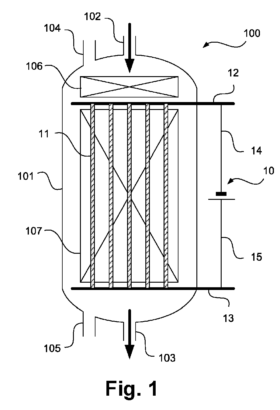
- Catalysis reactors according to embodiments of the invention are illustrated and designated 100 and 200, respectively. These each have a pressure vessel which is defined by a container wall 101.
- a cylindrical section can be provided, at both ends of which dome-shaped or hemispherical end caps are connected.
- These sections are in the Figures 1 and 2 each not designated separately.
- a gas inlet 102 and a gas outlet 103 open into the pressure vessels, each at the apical points of the dome-shaped or hemispherical end caps can be arranged.
- the direction of flow of a process gas containing hydrocarbons and steam, which enters the reactors 100, 200 via the respective gas inlets 102 and leaves the catalytic reactors 100, 200 via the respective gas outlets 103 at a temperature in the range explained above, is illustrated in bold arrows.
- a catalyst can be filled into the catalytic reactors 100, 200 via filling openings 104 which are designed, for example, in the manner of a manhole and are closed during operation. This can be removed from the catalytic reactors 100, 200, for example for replacement or external regeneration, via removal openings 104 that are closed during operation.
- the catalytic reactors 100, 200 are each designed for electrical heating and are provided with one or more power supply units 10 for this purpose.
- the type of power supply is arbitrary and can be done, for example, via a transformer, rectifier or the like from a power network or a generator. Heating is carried out by means of heating elements, illustrated hatched and each designated 11 at one point, which can in particular be designed as heating elements of the type mentioned above.
- the heating elements 11 are contacted through the container wall 101 via, in particular, high-temperature-resistant current feedthroughs 12, 13 (in Figure 2 not marked separately at each point, but always illustrated with bold lines). Further power connections are designated 14 and 15.
- the representation is greatly simplified.
- different groups of heating elements 11 or different heating elements 11 can be fed with the same or different currents from different power sources.
- At least one current-carrying element can also be used as a catalyst support.
- These longitudinal flow units can also be connected in series. Individual elements can be electrically connected in series. The voltage range can be either low voltage or medium voltage. In partial load operation, individual elements (heating elements or heating packages in series) can be switched off or the voltage can be reduced.
- Illustrated catalyst reactor 100 is a catalyst pre-bed 106, which in particular is not separately electrically heated, arranged upstream of a main catalyst bed 107, which in turn can also be divided into different partial beds and is heated by means of several heating elements 11, illustrated here parallel to the flow direction of the process gas.
- a catalyst pre-bed 106 which in particular is not separately electrically heated, arranged upstream of a main catalyst bed 107, which in turn can also be divided into different partial beds and is heated by means of several heating elements 11, illustrated here parallel to the flow direction of the process gas.
- the reactor wall can in particular be thermally insulated or have an appropriate lining so that the pressure vessel remains below the reaction temperatures. This enables more cost-effective material selection and production.
- a lining can be done, for example, by brick lining.
- the container wall can be cooled by a gas or cooling water, although this is not shown separately for reasons of clarity.
- the catalyst beds 108 to 117 are arranged one after the other in the flow direction in the catalysis reactor 200. These are heated alternately with heating elements 101, whereby the number, size, and heating or non-heating carried out in each case are not determined by the exemplary embodiment illustrated here.
- a graded heating of the catalytic reactor 200 can be achieved, with all heating elements 101 being able to be connected to a power source or to different power sources, as illustrated with dotted lines, and can be subjected to different voltages, for example.
- the advantage of this variant is a transverse flow across the heating elements, which leads to significantly higher heat transfer.
- Support structures intended to support the catalyst are not shown, but are known, for example, from reactors for autothermal reforming.
Landscapes
- Chemical & Material Sciences (AREA)
- Organic Chemistry (AREA)
- Chemical Kinetics & Catalysis (AREA)
- Physics & Mathematics (AREA)
- Fluid Mechanics (AREA)
- Hydrogen, Water And Hydrids (AREA)
Abstract
Ein Verfahren zur Durchführung einer katalytischen Gasphasenreaktion, insbesondere einer Hochtemperaturreaktion zur Herstellung von Wasserstoff, insbesondere einer Dampfreformierung, wird vorgeschlagen, bei dem ein Prozessgas durch einen Katalysereaktor (100, 200) geführt wird, wobei der Katalysereaktor (100, 200) einen Druckbehälter (101) aufweist, in dem ein oder mehrere Katalysatorbetten (106-117) angeordnet sind, wobei durch das eine Katalysatorbett (106-117) oder durch zumindest eines der mehreren Katalysatorbetten (106-111) ein oder mehrere Heizelemente (11) geführt ist oder sind, das oder die elektrisch beheizt wird oder werden. Ein entsprechender Katalysereaktor (100, 200) wird ebenfalls vorgeschlagen.
Description
Die Erfindung betrifft ein Verfahren und eine Anlage zur Durchführung einer katalytischen Gasphasenreaktion, insbesondere einer Hochtemperaturreaktion zur Herstellung von Wasserstoff, insbesondere einer Dampfreformierung.The invention relates to a method and a system for carrying out a catalytic gas phase reaction, in particular a high-temperature reaction for producing hydrogen, in particular steam reforming.
Die Erzeugung von Wasserstoff erfolgt derzeit noch überwiegend auf Basis von Kohlenwasserstoffen, beispielsweise durch Dampfreformierung von Erdgas oder anderen kohlenwasserstoffhaltigen Einsatzstoffen (Steam Methan Reforming, SMR). Da derartige Verfahren einen beträchtlichen Kohlendioxid-Fußabdruck aufweisen, wird der bereitgestellte Wasserstoff auch als "grauer" Wasserstoff bezeichnet.Hydrogen is currently produced primarily on the basis of hydrocarbons, for example through steam reforming of natural gas or other hydrocarbon-containing feedstocks (steam methane reforming, SMR). Because such processes have a significant carbon footprint, the hydrogen provided is also referred to as “gray” hydrogen.
Im Zuge der Klimadiskussion und entsprechender regulatorischer Maßnahmen bekommt die Vermeidung und Rückgewinnung von Kohlendioxid zunehmend an Bedeutung. Eine langfristig angestrebte Lösung kann beispielsweise die Gewinnung von Wasserstoff mittels Elektrolyse umfassen, die bei Einsatz von erneuerbaren Energiequellen kohlendioxidneutral sein kann, so dass entsprechend hergestellter Wasserstoff auch als "grün" bezeichnet wird.In the course of the climate discussion and corresponding regulatory measures, the avoidance and recovery of carbon dioxide is becoming increasingly important. A long-term solution could include, for example, the production of hydrogen using electrolysis, which can be carbon dioxide-neutral when using renewable energy sources, so that hydrogen produced accordingly is also referred to as "green".
Zumindest bis zur wirtschaftlich erfolgreichen Realisierung von Verfahren zur Herstellung von "grünem" Wasserstoff können Brückentechnologien eingesetzt werden. Diese umfassen insbesondere die Rückgewinnung und Lagerung oder Verwendung von Kohlendioxid (engl. Carbon (Dioxide) Capture and Storage, CCS bzw. Carbon (Dioxide) Capture and Utilization, CCU). In diesem Fall wird entsprechender Wasserstoff auch als "blau" bezeichnet.At least until processes for producing “green” hydrogen are economically successful, bridging technologies can be used. These include in particular the recovery and storage or use of carbon dioxide (Carbon (Dioxide) Capture and Storage, CCS or Carbon (Dioxide) Capture and Utilization, CCU). In this case, corresponding hydrogen is also referred to as “blue”.
Entsprechende Ausgestaltungen von Dampfreformierungsverfahren sind in der
In den genannten Verfahren wird weiterhin eine beträchtliche Menge von Kohlendioxid in einer Wassergasshift und durch die Verbrennung fossiler Brennstoffe gebildet, und die Abtrennung sowie Lagerung bzw. Verwertung von Kohlendioxid ist nicht immer gewünscht bzw. erweist sich in bestimmten Fällen als aufwendig.In the processes mentioned, a considerable amount of carbon dioxide is also formed in a water gas shift and through the combustion of fossil fuels, and the separation and storage or utilization of carbon dioxide is not always desired or proves to be complex in certain cases.
Die Entfernung von Kohlendioxid aus dem Prozessgas stellt dabei eine sehr konkurrenzfähige Lösung dar, erfordert jedoch immer noch eine (weitgehende) Dekarbonisierung des Brennstoffs, um Kohlendioxidemissionen im Rauchgas zu verringern oder zu vermeiden. Es ist zwar möglich, kohlenwasserstofffreie Brenngase wie Wasserstoff oder Ammoniak zu verwenden, allerdings ist die Bereitstellung solcher Brenngase typischerweise vergleichsweise kostenintensiv und aufwendig. Auch kann es bei diesen Brennstoffen zu vermehrter Stickoxidbildung kommen, was eine aufwendige Abgasnachbehandlung notwendig macht.Removing carbon dioxide from the process gas represents a very competitive solution, but still requires (large) decarbonization of the fuel in order to reduce or avoid carbon dioxide emissions in the flue gas. Although it is possible to use hydrocarbon-free fuel gases such as hydrogen or ammonia, the provision of such fuel gases is typically comparatively costly and complex. These fuels can also lead to increased nitrogen oxide formation, which makes complex exhaust gas aftertreatment necessary.
Daher besteht eine weitere, momentan in intensiver Entwicklung befindliche Alternative in der Beheizung der Katalysereaktoren mit elektrischem Strom, und vorzugsweise mit regenerativ erzeugtem Strom. Da hierbei auch weniger oder kein aufwendig in der Dampfreformierung erzeugter Wasserstoff verfeuert wird, können sich entsprechende Verfahren als deutlich effizienter erweisen, was die Ausbeute per eingesetztem Kohlenwasserstoff, beispielsweise Erdgas, angeht.Therefore, another alternative that is currently being intensively developed is to heat the catalytic reactors with electrical power, and preferably with electricity generated from renewable sources. Since less or no hydrogen that is produced at great expense in steam reforming is burned, corresponding processes can prove to be significantly more efficient in terms of the yield of the hydrocarbon used, for example natural gas.
In der Patent- und Nichtpatentliteratur existiert eine Reihe von Ansätzen zur Beheizung entsprechender Katalysereaktoren. Neben einer direkten resistiven Beheizung des Katalysators selbst oder eines Trägers, auf den dieser beispielsweise durch eine Waschbeschichtung aufgetragen ist, können dabei auch resistive Heizelemente eingesetzt werden. Auch kann eine Überhitzung des Prozessgases vorgenommen werden, das dann mit erhöhter Temperatur durch das Katalysatorbett strömt.There are a number of approaches to heating corresponding catalytic reactors in the patent and non-patent literature. In addition to direct resistive heating of the catalyst itself or a support to which it is applied, for example by means of a wash coating, resistive heating elements can also be used. The process gas can also be overheated, which then flows through the catalyst bed at an elevated temperature.
Neben einer direkten Beheizung, bei der das Heizmittel, beispielsweise ein Heizelement, eine Heizmanschette oder ein resistiv beheizter Katalysatorträger in stofflichem Kontakt mit dem Prozessgas oder im Materialkontakt zu Reaktionsrohren, durch die das Prozessgas strömt, steht, kann auch eine indirekte elektrische Beheizung eingesetzt werden, wie unter anderem in der
Eine derartige indirekte elektrische Beheizung kann unter Verwendung von elektrischen Strahlungsheizelementen erfolgen, die zum Erhitzen auf die für die genannten Reaktionen erforderlichen hohen Temperaturen geeignet sind, wobei derartige Heizelemente derart angeordnet sind, dass diese nicht in direktem Kontakt mit den Reaktionsrohen stehen. Die Wärmeübertragung erfolgt dabei überwiegend oder ausschließlich in Form von Strahlungswärme.Such indirect electrical heating can be carried out using electrical radiant heating elements which are suitable for heating to the high temperatures required for the reactions mentioned, such heating elements being arranged in such a way that they are not in direct contact with the reaction tubes. The heat transfer takes place predominantly or exclusively in the form of radiant heat.
Als weitere Alternative ist auch eine induktive Beheizung des Katalysators bzw. der Reaktionsrohre möglich, wie beispielsweise in der
Die Verwendung von elektrischer Wärme ist für die Reformierung insgesamt von großem Vorteil, da auf diese Weise Rauchgas vermieden oder signifikant reduziert wird. Allerdings ist die direkte Widerstandsheizung der Reaktionsrohre in bestimmten Fällen wirtschaftlich nicht attraktiv, da sehr hohe Stromdichten aufgebracht werden müssen, wenn die konventionelle Rohrgeometrie (relativ großer Rohrdurchmesser und Rohrwandstärke zur Aufnahme einer Katalysatormenge und relativ hoher Prozessdruck) beibehalten wird. Der Wechsel zu einem geringeren Rohrdurchmesser würde die Kosten für die Rohre drastisch erhöhen. Daher besteht hier ein Bedarf nach Verbesserungen.The use of electrical heat is of great advantage for reforming as a whole, as it avoids or significantly reduces flue gas. However, direct resistance heating of the reaction tubes is not economically attractive in certain cases because very high current densities have to be applied if the conventional tube geometry (relatively large tube diameter and tube wall thickness to accommodate an amount of catalyst and relatively high process pressure) is maintained. Switching to a smaller pipe diameter would dramatically increase the cost of the pipes. Therefore, there is a need for improvements here.
Generell sind Ausgestaltungen der vorliegenden Erfindung dabei nicht auf die Herstellung von Wasserstoff durch Dampfreformierung beschränkt, sondern auch in anderen, bei entsprechenden oder vergleichbar hohen Temperaturen durchgeführte katalytische Gasphasenreaktionen einsetzbar, wie weiter unten erläutert.In general, embodiments of the present invention are not limited to the production of hydrogen by steam reforming, but can also be used in other catalytic gas phase reactions carried out at corresponding or comparably high temperatures, as explained further below.
Vor diesem Hintergrund schlägt die vorliegende Erfindung ein Verfahren und eine Anlage zur Durchführung einer katalytischen Gasphasenreaktion, insbesondere einer Hochtemperaturreaktion zur Herstellung von Wasserstoff, insbesondere einer Dampfreformierung mit den Merkmalen der unabhängigen Patentansprüche vor. Ausgestaltungen sind Gegenstand der abhängigen Patentansprüche sowie der nachfolgenden Beschreibung.Against this background, the present invention proposes a method and a system for carrying out a catalytic gas phase reaction, in particular a high-temperature reaction for producing hydrogen, in particular steam reforming, with the features of the independent claims. Refinements are the subject of the dependent patent claims and the following description.
Ausgestaltungen der vorliegenden Erfindung betreffen ein Konzept zur Vermeidung von Reaktionsrohren bei der Dampfreformierung oder einer anderen katalytischen Gasphasenreaktion der nachfolgend noch genauer erläuterten Art unter Verwendung von elektrischem Strom zur Beheizung. Wenngleich nachfolgend überwiegend von einer Dampfreformierung die Rede ist, ergeben sich die hierzu erläuterten Vorteile auch für die jeweils anderen Gasphasenreaktionen, so dass eine entsprechende Bezugnahme auf eine Dampfreformierung nur der Vereinfachung dient, jedoch den Gegenstand der Erfindung nicht einschränkt.Embodiments of the present invention relate to a concept for avoiding reaction tubes in steam reforming or another catalytic gas phase reaction of the type explained in more detail below using electrical current for heating. Although steam reforming is mainly referred to below, the advantages explained in this regard also apply to the other gas phase reactions, so that a corresponding reference to steam reforming only serves to simplify things, but does not limit the subject matter of the invention.
Hierbei kann insbesondere ein isolierter Druckbehälter verwendet werden, der vergleichbar zu einem in der autothermen Reformierung eingesetzten Druckbehälter aufgebaut und mit herkömmlichen Katalysatorpartikeln gefüllt sein kann, die eine entsprechende Reaktion katalysieren. Die Wärme wird unter Verwendung von elektrischen Heizelementen bereitgestellt, die in dem Druckbehälter aufgenommen sind. Der Druckbehälter wird insbesondere auf einem Druck in einem Bereich von 10 bis 100bar, weiter insbesondere 10 bis 70bar, beispielsweise 10 bis 50bar, betrieben. Bei höheren Drücken ergeben sich Vorteile gegenüber herkömmlichen Reformierverfahren, bei denen der Druck nicht über 35bar liegt.In particular, an insulated pressure vessel can be used here, which can be constructed comparable to a pressure vessel used in autothermal reforming and can be filled with conventional catalyst particles that catalyze a corresponding reaction. The heat is provided using electrical heating elements housed in the pressure vessel. The pressure vessel is operated in particular at a pressure in a range of 10 to 100 bar, more particularly 10 to 70 bar, for example 10 to 50 bar. At higher pressures there are advantages over conventional reforming processes in which the pressure does not exceed 35 bar.
Es wird dabei ein Verfahren zur Durchführung einer katalytischen Gasphasenreaktion, insbesondere einer Hochtemperaturreaktion zur Herstellung von Wasserstoff, insbesondere einer Dampfreformierung, vorgeschlagen, bei dem ein Prozessgas, insbesondere für die Dampfreformierung ein kohlenwasserstoff- und dampfhaltiges Prozessgas, durch einen Katalysereaktor geführt wird, wobei der Katalysereaktor einen Druckbehälter aufweist, in dem ein oder mehrere Katalysatorbetten angeordnet sind, wobei durch das eine Katalysatorbett oder durch zumindest eines der mehreren Katalysatorbetten ein oder mehrere Heizelemente geführt ist oder sind, das oder die elektrisch beheizt wird oder werden. Das Prozessgas kann beispielsweise auch Kohlendioxid enthalten. Dies ist insbesondere dann der Fall, wenn eine Synthesegasherstellung mit geringerem Verhältnis von Wasserstoff zu Kohlendioxid als bei der Dampfreformierung erfolgt. Je nach durchgeführter Reaktion können unterschiedliche Reaktanden im Prozessgas bereitgestellt sein.A method for carrying out a catalytic gas phase reaction, in particular a high-temperature reaction for producing hydrogen, in particular steam reforming, is proposed, in which a process gas, in particular a process gas containing hydrocarbons and steam for steam reforming, is passed through a catalysis reactor, the catalysis reactor has a pressure vessel in which one or more catalyst beds are arranged, wherein one or more heating elements are guided through the one catalyst bed or through at least one of the plurality of catalyst beds, which is or are electrically heated. The process gas can also contain carbon dioxide, for example. This is particularly the case when synthesis gas is produced with a lower ratio of hydrogen to carbon dioxide than with steam reforming. Depending on the reaction carried out, different reactants can be provided in the process gas.
Der Katalysereaktor ist insbesondere dadurch zur Durchführung der katalytischen Gasphasenreaktion eingerichtet, dass er einen hierfür geeigneten Katalysator aufweist, mit dem Prozessgas in einer geeigneten Zusammensetzung und mit einer geeigneten Temperatur beschickt wird, und dass er zur Beheizung auf eine geeignete Temperatur ausgebildet ist. Ferner ist ein entsprechender Katalysereaktor zur Durchströmung mit einer für die Durchführung der katalytischen Gasphasenreaktion geeigneten Strömungsgeschwindigkeit, Verweildauer und dergleichen ausgebildet. Hierzu sieht der Fachmann geeignete Steuer- bzw. Regelmittel vor und stützt sich auf einschlägige Fachliteratur. Sämtliche für Durchführung der katalytischen Gasphasenreaktion geeignete Katalysatoren und Reaktionsbedingungen können grundsätzlich auch im Rahmen von Ausgestaltungen der vorliegenden Erfindung eingesetzt werden.The catalytic reactor is set up in particular to carry out the catalytic gas phase reaction in that it has a catalyst suitable for this purpose, is charged with the process gas in a suitable composition and at a suitable temperature, and that it is designed to be heated to a suitable temperature. Furthermore, a corresponding catalytic reactor is designed for flow through at a flow rate, residence time and the like that is suitable for carrying out the catalytic gas phase reaction. For this purpose, the expert provides suitable control or regulation means and relies on relevant specialist literature. All catalysts and reaction conditions suitable for carrying out the catalytic gas phase reaction can in principle also be used within the scope of embodiments of the present invention.
In einer Ausgestaltung der vorliegenden Erfindung weist der Druckbehälter einen Innenraum mit einem kreisförmigen Querschnitt auf, dessen Durchmesser mehr als 1m, insbesondere mehr als 2m, mehr als 3m oder mehr als 5 m und insbesondere bis zu 10m beträgt, wobei das eine Katalysatorbett oder zumindest eines der mehreren Katalysatorbetten zumindest 50% des Querschnitts einnimmt. Der erfindungsgemäß vorgeschlagene Katalysereaktor grenzt sich dabei deutlich von herkömmlichen Katalysereaktoren ab, in denen in einem befeuerten Raum eine Vielzahl von Reaktionsrohren (Coils) angeordnet ist. Der Druckbehälter kann insbesondere einen zylindrischen Abschnitt aufweisen, auf welchen sich der erwähnte Querschnitt bezieht. Bei nichtzylindrischen Druckbehältern bezeichnet der Querschnitt die durchströmbare Fläche an der größten Stelle.In one embodiment of the present invention, the pressure vessel has an interior with a circular cross section, the diameter of which is more than 1m, in particular more than 2m, more than 3m or more than 5m and in particular up to 10m, with the one catalyst bed or at least one of the several catalyst beds takes up at least 50% of the cross section. The catalysis reactor proposed according to the invention is clearly differentiated from conventional catalysis reactors, in which a large number of reaction tubes (coils) are arranged in a fired space. The pressure vessel can in particular have a cylindrical section to which the cross section mentioned relates. For non-cylindrical pressure vessels, the cross section refers to the area that can be flowed through at the largest point.
Insbesondere kann bzw. können das eine oder zumindest eines der mehreren Heizelemente stabförmig ausgebildet sein. Hierbei können grundsätzlich aus der Fachliteratur bekannte bzw. kommerziell verfügbare Heizstäbe eingesetzt werden, die sich für einen hier in Betracht kommenden Temperaturbereich eignen. Weitere Details zu entsprechenden Heizelementen sind unten erläutert.In particular, the one or at least one of the several heating elements can be designed to be rod-shaped. In principle, heating elements that are known from the specialist literature or are commercially available can be used, which are suitable for the temperature range in question here. Further details on corresponding heating elements are explained below.
In Ausgestaltungen der vorliegenden Erfindung kann bzw. können das eine oder zumindest eines der mehreren Heizelemente in einem Winkel von weniger als 10° oder in einem Winkel zwischen 80° und 100° gegenüber einer Längsachse des Druckbehälters ausgerichtet sein. Mit anderen Worten können sich die Heizelemente im Wesentlichen längs oder quer zur Längsachse erstrecken. Erstere Ausgestaltung bietet dabei den Vorteil, dass nur wenige lange Heizelemente bereitgestellt werden müssen, wodurch sich der Aufwand für die Bereitstellung und Kontaktierung mittels hochtemperaturfester Stromdurchführungen verringert. Letztere Ausgestaltung kann im Zusammenhang mit einer unterschiedlichen Beheizung längs des Katalysereaktors eingesetzt werden, wobei entsprechende Vorteile unten erläutert sind. Aber auch bei einer Längsanordnung, d.h. in ersterer Ausgestaltung, können mehrere sequentielle Abschnitte mit separaten, segmentierten oder unterschiedlich vielen Heizelementen ausgestattet werden, wodurch sich die Temperaturen in unterschiedlichen Abschnitten gezielt steuern lassen. Hierdurch lassen sich Verkokungen verringern oder vermeiden und eine Degradation des Katalysators bzw. der Heizelemente kann gezielt ausgeglichen werden.In embodiments of the present invention, the one or at least one of the plurality of heating elements can be aligned at an angle of less than 10° or at an angle between 80° and 100° with respect to a longitudinal axis of the pressure vessel. In other words, the heating elements can extend essentially longitudinally or transversely to the longitudinal axis. The former embodiment offers the advantage that only a few long heating elements have to be provided, which means that the effort for the provision and contacting is reduced high-temperature-resistant power feedthroughs reduced. The latter embodiment can be used in connection with different heating along the catalytic reactor, with corresponding advantages being explained below. But even with a longitudinal arrangement, ie in the first embodiment, several sequential sections can be equipped with separate, segmented or different numbers of heating elements, whereby the temperatures in different sections can be controlled in a targeted manner. In this way, coking can be reduced or avoided and degradation of the catalytic converter or heating elements can be specifically compensated for.
Insbesondere können in Ausgestaltungen der vorliegenden Erfindung in dem Druckbehälter mehrere der Katalysatorbetten bereitgestellt und in einer Strömungsrichtung des Prozessgases hintereinander angeordnet sein, und es können mehrere der Heizelemente bereitgestellt sein. Hierbei kann bzw. können durch ein erstes Katalysatorbett der Katalysatorbetten oder durch eine erste Gruppe der Katalysatorbetten zumindest eines oder jeweils zumindest eines der Heizelemente geführt sein, wohingegen durch ein zweites Katalysatorbett der Katalysatorbetten oder eine zweite Gruppe der Katalysatorbetten keines oder jeweils keines der Heizelemente geführt sein können. Auf diese Weise können bestimmte Katalysatorbetten gezielt unbeheizt belassen werden, wodurch beispielsweise ein Vorreformierbett oder Zwischenbetten gebildet werden können, die jeweils zur Verhinderung oder Verringerung einer Verkokung dienen. Unterschiedliche Katalysatorbetten können dabei jeweils auch mit (in sich oder gegenüber anderen Katalysatorbetten) unterschiedlichen Katalysatoren, Katalysatorbeladungen oder Katalysatoraktivitäten ausgebildet sein und unterschiedliche Volumina aufweisen.In particular, in embodiments of the present invention, several of the catalyst beds can be provided in the pressure vessel and arranged one behind the other in a flow direction of the process gas, and several of the heating elements can be provided. Here, at least one or at least one of the heating elements can be guided through a first catalyst bed of the catalyst beds or through a first group of the catalyst beds, whereas none or none of the heating elements can be guided through a second catalyst bed of the catalyst beds or a second group of the catalyst beds can. In this way, certain catalyst beds can be left unheated in a targeted manner, whereby, for example, a pre-reforming bed or intermediate beds can be formed, each of which serves to prevent or reduce coking. Different catalyst beds can each be designed with different catalysts, catalyst loadings or catalyst activities (in themselves or compared to other catalyst beds) and have different volumes.
Die erste Gruppe der Katalysatorbetten und die zweite Gruppe der Katalysatorbetten können in einer Ausgestaltung der vorliegenden Erfindung Katalysatorbetten aufweisen, die alternierend zueinander in der Strömungsrichtung des Prozessgases hintereinander angeordnet sind. Auf diese Weise kann ggf. eine Verkokung besser verhindert werden, als wenn nur ein nicht beheiztes Katalysatorbett am Eintritt des Katalysereaktors bereitgestellt ist.In one embodiment of the present invention, the first group of catalyst beds and the second group of catalyst beds can have catalyst beds which are arranged one behind the other in an alternating manner in the flow direction of the process gas. In this way, coking can possibly be prevented better than if only an unheated catalyst bed is provided at the inlet of the catalytic reactor.
Im Rahmen von Ausgestaltungen der vorliegenden Erfindung können Stromführungsmittel bereitgestellt sein, die den Katalysator in zumindest einem der Katalysatorbetten abstützen. Auf diese Weise verringert sich der Aufwand für zusätzliche Abstützmittel in Form von Trägerelementen und dergleichen.Within the scope of embodiments of the present invention, current-carrying means can be provided which contain the catalyst in at least one of the Support catalyst beds. In this way, the effort for additional support means in the form of support elements and the like is reduced.
Das eine Heizelement oder zumindest eines der mehreren Heizelemente kann bzw. können in Ausgestaltungen der vorliegenden Erfindung in einem oder mehreren Schutzrohren angeordnet sein bzw. von einer oder mehreren Schutzschichten umgeben sein. Hierbei können unterschiedliche Arten der Realisierung gewählt werden, beispielsweise keramische Rohre, Beschichtungen, metallische Abstandshalter, Katalysator- oder inerte Keramikringe.In embodiments of the present invention, the one heating element or at least one of the several heating elements can be arranged in one or more protective tubes or surrounded by one or more protective layers. Different types of implementation can be chosen, for example ceramic tubes, coatings, metallic spacers, catalyst or inert ceramic rings.
In Ausgestaltungen der vorliegenden Erfindung kann das eine Heizelement oder kann zumindest eines der mehreren Heizelemente ein hochtemperaturfestes Material, insbesondere eine (gesinterte) oxiddispersionsverfestigte Superlegierung, aufweisen, wie sie an sich aus dem Bereich der Hochtemperaturtechnik bekannt ist. Zu oxiddispersionsverfestigte Superlegierungen, die im Rahmen der vorliegenden Erfindung zum Einsatz kommen, sowie deren mögliche Komponenten und Ausgestaltungen, Basiswerkstoffe, zur Verfestigung einsetzbare Oxidpartikel und deren Grundelemente usw. sei auf einschlägige Fachliteratur verwiesen. Auch die Verwendung von Materialien wie Siliciumcarbid ist möglich.In embodiments of the present invention, the one heating element or at least one of the several heating elements can have a high-temperature-resistant material, in particular a (sintered) oxide dispersion-strengthened superalloy, as is known per se from the field of high-temperature technology. For oxide dispersion-strengthened superalloys that are used in the context of the present invention, as well as their possible components and designs, base materials, oxide particles that can be used for solidification and their basic elements, etc., please refer to the relevant specialist literature. The use of materials such as silicon carbide is also possible.
In Ausgestaltungen der Erfindung kann beispielsweise ein pulvermetallurgisch hergestellte, dispersionsverfestigte, ferritische Eisen-Chrom-Aluminium-Legierung, die sich für den Einsatz bei Temperaturen bis zu 1.425°C eignet, eingesetzt werden. Eine derartige Legierung zeichnet sich durch außergewöhnlich gute Formstabilität und Oxidationsbeständigkeit aus.In embodiments of the invention, for example, a powder-metallurgically produced, dispersion-strengthened, ferritic iron-chromium-aluminum alloy, which is suitable for use at temperatures up to 1,425 ° C, can be used. Such an alloy is characterized by exceptionally good dimensional stability and oxidation resistance.
Das Prozessgas kann im Rahmen der vorliegenden Erfindung auf einer Einspeisetemperatur in einem Bereich von 500 bis 700°C, beispielsweise ca. 550°C, in den Katalysereaktor eingespeist werden, und die elektrische Beheizung kann derart vorgenommen werden, dass das Prozessgas auf einer Entnahmetemperatur in einem Bereich von 800 bis 1.050°C, beispielsweise ca. 850°C, aus dem Katalysereaktor ausströmt. Die vorliegende Erfindung ermöglicht auch bei derartigen Temperaturen eine verbesserte elektrische Beheizung. Eine Einspeisetemperatur kann auch bei 350 bis 500°C liegen, wodurch eine Rauchgasüberhitzung eingespart werden kann.In the context of the present invention, the process gas can be fed into the catalytic reactor at a feed temperature in a range of 500 to 700 ° C, for example approximately 550 ° C, and the electrical heating can be carried out in such a way that the process gas is at a withdrawal temperature in a range from 800 to 1,050 ° C, for example approx. 850 ° C, flows out of the catalytic reactor. The present invention enables improved electrical heating even at such temperatures. A feed temperature can also be 350 to 500°C, which can save flue gas overheating.
Ausgestaltungen der vorliegenden Erfindung umfassen, dass mehrere der Heizelemente bereitgestellt sind, die zumindest zum Teil auf unterschiedliche Temperaturen beheizt werden. Auf diese Weise kann eine graduelle Abstufung der Beheizung geschaffen werden. Insbesondere ist es auf diese Weise auch möglich, bestimmte Heizelemente, beispielsweise solche, die auf Temperaturen unterhalb von 650°C betrieben werden, mit weniger temperaturfesten, und damit kostengünstigeren und einfacher zu verarbeitenden Materialien auszubilden, elektrisch zu kontaktieren, abzustützen oder zu schützen.Embodiments of the present invention include that several of the heating elements are provided, which are at least partially heated to different temperatures. In this way, a gradual gradation of heating can be created. In particular, it is also possible in this way to design, electrically contact, support or protect certain heating elements, for example those that are operated at temperatures below 650 ° C, with materials that are less temperature-resistant and therefore more cost-effective and easier to process.
Für die Bestromung unterschiedlicher Heizelemente oder Gruppen von Heizelementen können in Ausgestaltungen der vorliegenden Erfindung unterschiedliche Stromquellen, Stromwandler, Netze, Generatoren oder dergleichen eingesetzt werden. Es können aber auch alle Heizelemente gemeinsam bestromt werden.In embodiments of the present invention, different power sources, current converters, networks, generators or the like can be used to power different heating elements or groups of heating elements. However, all heating elements can also be energized together.
Der in einem entsprechenden Verfahren eingesetzte Katalysereaktor kann in Ausgestaltungen der vorliegenden Erfindung auch einer von mehreren, gleichartig aufgebauten und seriell angeordneten Katalysereaktoren sein. Auch eine Hintereinander- bzw. Parallelschaltung von elektrisch beheizten Katalysereaktoren, wie sie die vorliegende Erfindung in ihren Ausgestaltungen vorschlägt, und konventionellen Katalysereaktoren bzw. Reaktoren zur autothermen Reformierung und/oder partiellen Oxidation beliebiger Art ist möglich.In embodiments of the present invention, the catalysis reactor used in a corresponding process can also be one of several catalysis reactors of similar structure and arranged in series. A series or parallel connection of electrically heated catalysis reactors, as proposed by the present invention in its embodiments, and conventional catalysis reactors or reactors for autothermal reforming and/or partial oxidation of any type is also possible.
Wie erwähnt, eignet sich die vorliegende Erfindung insbesondere zur Durchführung einer Dampfreformierung, die mit oder ohne Einsatz von Kohlendioxid durchgeführt werden kann. Die Gasphasenreaktion kann jedoch auch eine andere endotherme Hochtemperaturreaktion sein, und beispielsweise das sogenannte Ammoniakcracking oder eine reverse Wassergasshift umfassen. Auch Dehydrierungsreaktionen wie eine Propandehydrierung, eine Butandehydrierung, eine Butendehydrierung oder eine Ethylbenzoldehydrierung können entsprechende Gasphasenreaktionen darstellen. In jedem Fall umfasst das Prozessgas bei der Einspeisung in den Katalysereaktor zumindest einige Reaktanden für eine entsprechende Reaktion, beispielsweise ausgewählt aus Dampf, Kohlendioxid, Kohlenwasserstoffen und Ammoniak.As mentioned, the present invention is particularly suitable for carrying out steam reforming, which can be carried out with or without the use of carbon dioxide. However, the gas phase reaction can also be another endothermic high-temperature reaction, and can include, for example, so-called ammonia cracking or a reverse water gas shift. Dehydrogenation reactions such as propane dehydrogenation, butane dehydrogenation, butane dehydrogenation or ethylbenzene dehydrogenation can also represent corresponding gas phase reactions. In any case, when fed into the catalytic reactor, the process gas comprises at least some reactants for a corresponding reaction, for example selected from steam, carbon dioxide, hydrocarbons and ammonia.
Der vorgeschlagene Katalysereaktor ist zur Durchführung einer katalytischen Gasphasenreaktion, insbesondere einer Hochtemperaturreaktion zur Herstellung von Wasserstoff, insbesondere einer Dampfreformierung, umfassend eine Umsetzung eines durch den Katalysereaktor geführten Prozessgases; eingerichtet, wobei der Katalysereaktor und einen Druckbehälter aufweist, in dem ein oder mehrere Katalysatorbetten angeordnet sind, wobei durch das eine Katalysatorbett oder durch zumindest eines der mehreren Katalysatorbetten ein oder mehrere Heizelemente geführt ist oder sind, das oder die zur elektrischen Beheizung eingerichtet ist oder sind.The proposed catalysis reactor is designed to carry out a catalytic gas phase reaction, in particular a high-temperature reaction for the production of Hydrogen, in particular a steam reforming, comprising a reaction of a process gas passed through the catalytic reactor; set up, wherein the catalytic reactor and has a pressure vessel in which one or more catalyst beds are arranged, wherein one or more heating elements are guided through the one catalyst bed or through at least one of the plurality of catalyst beds, which is or are set up for electrical heating .
Zu weiteren Merkmalen und Vorteilen eines entsprechenden Katalysereaktors und Ausgestaltungen hiervon sei auf die obigen Erläuterungen betreffend das erfindungsgemäß vorgeschlagene Verfahren und seine Ausgestaltungen ausdrücklich verwiesen, da diese hierfür in gleicher Weise gelten.For further features and advantages of a corresponding catalytic reactor and configurations thereof, reference is expressly made to the above explanations regarding the method proposed according to the invention and its configurations, since these apply in the same way.
Entsprechendes gilt auch für einen Katalysereaktor, der gemäß einer Ausgestaltung der Erfindung dazu eingerichtet ist, ein Verfahren gemäß einer beliebigen Ausgestaltung der vorliegenden Erfindung durchzuführen.The same also applies to a catalysis reactor which, according to an embodiment of the invention, is set up to carry out a method according to any embodiment of the present invention.
Ausführungsformen der Erfindung werden nachfolgend rein beispielhaft unter Bezugnahme auf die beigefügte Zeichnung beschrieben, wobei
-
Figur 1 einen Katalysereaktor gemäß einer ersten Ausgestaltung der vorliegenden Erfindung veranschaulicht, und -
Figur 2 einen Katalysereaktor gemäß einer zweiten Ausgestaltung der vorliegenden Erfindung veranschaulicht.
-
Figure 1 illustrates a catalytic reactor according to a first embodiment of the present invention, and -
Figure 2 illustrates a catalytic reactor according to a second embodiment of the present invention.
Die nachfolgend beschriebenen Ausführungsformen werden lediglich zu dem Zweck beschrieben, den Leser beim Verständnis der beanspruchten und zuvor erläuterten Merkmale zu unterstützen. Sie stellen lediglich repräsentative Beispiele dar und sollen hinsichtlich der Merkmale der Erfindung nicht abschließend und/oder beschränkend betrachtet werden. Es versteht sich, dass die zuvor und nachfolgend beschriebenen Vorteile, Ausführungsformen, Beispiele, Funktionen, Merkmale, Strukturen und/oder anderen Aspekte nicht als Beschränkungen des Umfangs der Erfindung, wie er in den Ansprüchen definiert ist, oder als Beschränkungen von Äquivalenten zu den Ansprüchen zu betrachten sind, und dass andere Ausführungsformen verwendet und Änderungen vorgenommen werden können, ohne vom Umfang der beanspruchten Erfindung abzuweichen.The embodiments described below are described solely for the purpose of assisting the reader in understanding the claimed and previously explained features. They merely represent representative examples and are not intended to be considered exhaustive and/or limiting with regard to the features of the invention. It is understood that the advantages, embodiments, examples, functions, features, structures and/or described above and below other aspects are not to be regarded as limitations on the scope of the invention as defined in the claims or as limitations on equivalents to the claims, and that other embodiments may be used and changes may be made without departing from the scope of the claimed invention.
Unterschiedliche Ausführungsformen der Erfindung können weitere zweckmäßige Kombinationen der beschriebenen Elemente, Komponenten, Merkmale, Teile, Schritte, Mittel usw. umfassen, aufweisen, aus ihnen bestehen oder im Wesentlichen aus ihnen bestehen, auch wenn solche Kombinationen hier nicht spezifisch beschrieben sind. Darüber hinaus kann die Offenbarung andere Erfindungen umfassen, die gegenwärtig nicht beansprucht sind, die aber in Zukunft beansprucht werden können, insbesondere wenn sie vom Umfang der unabhängigen Ansprüche umfasst sind.Different embodiments of the invention may include, have, consist of, or consist essentially of other useful combinations of the described elements, components, features, parts, steps, means, etc., even if such combinations are not specifically described herein. In addition, the disclosure may include other inventions that are not currently claimed but that may be claimed in the future, particularly if included within the scope of the independent claims.
Erläuterungen, die sich auf Vorrichtungen, Apparate, Anordnungen, Systeme usw. gemäß Ausführungsformen der vorliegenden Erfindung beziehen, können auch für Verfahren, Prozesse, Methoden usw. gemäß den Ausführungsformen der vorliegenden Erfindung gelten und umgekehrt. Gleiche, gleich wirkende, in ihrer Funktion einander entsprechende, baulich identisch oder vergleichbar aufgebaute Elemente, Verfahrensschritte usw. können mit identischen Bezugszeichen angegeben sein.Explanations that relate to devices, apparatus, arrangements, systems, etc. according to embodiments of the present invention may also apply to methods, processes, methods, etc. according to embodiments of the present invention and vice versa. Elements, process steps, etc. that are the same, have the same effect, correspond in their function, are structurally identical or comparable, can be indicated with identical reference numerals.
In den
Erneut wird nachfolgend auf eine Dampfreformierung Bezug genommen, wobei die entsprechenden Erläuterungen jedoch nicht einschränkend zu verstehen sind.Reference will again be made below to steam reforming, although the corresponding explanations are not to be understood as restrictive.
Wie insoweit für entsprechende Druckbehälter üblich, kann dabei jeweils ein zylindrischer Abschnitt vorgesehen sein, an dessen beiden Enden sich kalottenförmige oder halbkugelige Endkappen anschließen. Diese Abschnitte sind in den
In die Druckbehälter münden jeweils ein Gaseinlass 102 und ein Gasauslass 103, die jeweils an den apikalen Punkten der kalottenförmigen oder halbkugeligen Endkappen angeordnet sein können. Die Strömungsrichtung eines kohlenwasserstoff- und dampfhaltigen Prozessgases, das in die Reaktoren 100, 200 über die jeweiligen Gaseinlässe 102 eintritt und mit einer Temperatur im oben erläuterten Bereich die Katalysereaktoren 100, 200 über die jeweiligen Gasauslässe 103 verlässt, ist dabei jeweils mit fetten Pfeilen veranschaulicht.A
Über beispielsweise nach Art eines Mannlochs ausgebildete, im Betrieb verschlossenen Einfüllöffnungen 104 kann jeweils ein Katalysator in die Katalysereaktoren 100, 200 eingefüllt werden. Dieser kann, beispielsweise zum Austausch oder zur externen Regeneration, jeweils über im Betrieb geschlossene Entnahmeöffnungen 104 den Katalysereaktoren 100, 200 entnommen werden.A catalyst can be filled into the
Die Katalysereaktoren 100, 200 sind jeweils zur elektrischen Beheizung ausgebildet und dazu mit einer oder mehreren Stromversorgungseinheiten 10 versehen. Die Art der Stromversorgung ist dabei beliebig und kann beispielsweise über einen Transformator, Gleichrichter oder dergleichen aus einem Stromnetz oder einem Generator erfolgen. Die Beheizung erfolgt mittels schraffiert veranschaulichter und jeweils an einer Stelle mit 11 bezeichneter Heizelemente, die insbesondere als Heizstäbe der zuvor erwähnten Art ausgebildet sein können.The
Die Heizelemente 11 werden dabei über insbesondere hochtemperaturfeste Stromdurchführungen 12, 13 durch die Behälterwand 101 kontaktiert (in
Diese längsangeströmten Einheiten können auch hintereinander geschaltet werden. Elektrisch können einzelne Elemente in Serie geschaltet werden. Der Spannungsbereich kann sowohl Niederspannung aber auch Mittelspannung sein. Im Teillastbetrieb können einzelne Elemente (Heizelemente oder Heizpakete in Serie) ausgeschaltet sein oder in der Spannung reduziert werden.These longitudinal flow units can also be connected in series. Individual elements can be electrically connected in series. The voltage range can be either low voltage or medium voltage. In partial load operation, individual elements (heating elements or heating packages in series) can be switched off or the voltage can be reduced.
Unterschiede zwischen den in
In dem in
Die Reaktorwand kann insbesondere thermisch isoliert sein bzw. eine entsprechende Auskleidung aufweisen, so dass der Druckbehälter unterhalb der Reaktionstemperaturen bleibt. Dies ermöglicht eine kostengünstigere Materialwahl und Fertigung. Eine Auskleidung kann beispielsweise durch eine Ausmauerung erfolgen. Zudem kann Behälterwand durch ein Gas oder Kühlwasser gekühlt werden, wie jedoch aus Gründen der Übersichtlichkeit nicht gesondert gezeigt.The reactor wall can in particular be thermally insulated or have an appropriate lining so that the pressure vessel remains below the reaction temperatures. This enables more cost-effective material selection and production. A lining can be done, for example, by brick lining. In addition, the container wall can be cooled by a gas or cooling water, although this is not shown separately for reasons of clarity.
In dem in
Auf diese Weise kann, mit den zuvor erläuterten Vorteilen, eine abgestufte Beheizung des Katalysereaktors 200 erzielt werden, wobei sämtliche Heizelemente 101 an eine Stromquelle oder an unterschiedliche Stromquellen angeschlossen werden können, wie mit punktierten Linien veranschaulicht, und beispielsweise mit unterschiedlichen Spannungen beaufschlagbar sind. Vorteil dieser Variante ist eine Queranströmung der Heizelemente, was zu wesentlich höheren Wärmeübertragungen führt.In this way, with the advantages explained above, a graded heating of the
Supportstrukturen, die dafür vorgesehen sind, den Katalysator zu tragen, ist nicht gezeigt, aber z.B. von Reaktoren zur autothermen Reformierung bekannt.Support structures intended to support the catalyst are not shown, but are known, for example, from reactors for autothermal reforming.
Claims (15)
Priority Applications (1)
| Application Number | Priority Date | Filing Date | Title |
|---|---|---|---|
| EP22020370.7A EP4316640A1 (en) | 2022-08-03 | 2022-08-03 | Method and assembly for the performance of a catalytic gas phase reaction |
Applications Claiming Priority (1)
| Application Number | Priority Date | Filing Date | Title |
|---|---|---|---|
| EP22020370.7A EP4316640A1 (en) | 2022-08-03 | 2022-08-03 | Method and assembly for the performance of a catalytic gas phase reaction |
Publications (1)
| Publication Number | Publication Date |
|---|---|
| EP4316640A1 true EP4316640A1 (en) | 2024-02-07 |
Family
ID=82839042
Family Applications (1)
| Application Number | Title | Priority Date | Filing Date |
|---|---|---|---|
| EP22020370.7A Withdrawn EP4316640A1 (en) | 2022-08-03 | 2022-08-03 | Method and assembly for the performance of a catalytic gas phase reaction |
Country Status (1)
| Country | Link |
|---|---|
| EP (1) | EP4316640A1 (en) |
Citations (4)
| Publication number | Priority date | Publication date | Assignee | Title |
|---|---|---|---|---|
| WO2017186437A1 (en) | 2016-04-26 | 2017-11-02 | Haldor Topsøe A/S | Induction heated reactor |
| WO2020002326A1 (en) | 2018-06-29 | 2020-01-02 | Shell Internationale Research Maatschappij B.V. | Electrically heated reactor and a process for gas conversions using said reactor |
| CN111185125A (en) * | 2020-01-08 | 2020-05-22 | 中国科学院工程热物理研究所 | Device and method for activating deactivated catalyst |
| WO2022093363A1 (en) * | 2020-10-30 | 2022-05-05 | Gas Technology Institute | Electrically heated reforming reactor for reforming of methane and other hydrocarbons |
-
2022
- 2022-08-03 EP EP22020370.7A patent/EP4316640A1/en not_active Withdrawn
Patent Citations (4)
| Publication number | Priority date | Publication date | Assignee | Title |
|---|---|---|---|---|
| WO2017186437A1 (en) | 2016-04-26 | 2017-11-02 | Haldor Topsøe A/S | Induction heated reactor |
| WO2020002326A1 (en) | 2018-06-29 | 2020-01-02 | Shell Internationale Research Maatschappij B.V. | Electrically heated reactor and a process for gas conversions using said reactor |
| CN111185125A (en) * | 2020-01-08 | 2020-05-22 | 中国科学院工程热物理研究所 | Device and method for activating deactivated catalyst |
| WO2022093363A1 (en) * | 2020-10-30 | 2022-05-05 | Gas Technology Institute | Electrically heated reforming reactor for reforming of methane and other hydrocarbons |
Similar Documents
| Publication | Publication Date | Title |
|---|---|---|
| EP4424411B1 (en) | Reactor for high temperature endothermic reactions | |
| EP4117811B1 (en) | Reactor and method for performing a chemical reaction | |
| EP2334592B1 (en) | Method and device for producing synthesis gas from gaseous hydrocarbons | |
| EP0991587B1 (en) | Method and device for reforming hydrocarbons autothermally | |
| EP4117810B1 (en) | Reactor and method for performing a chemical reaction | |
| EP4103315A1 (en) | Reactor and method for carrying out a chemical reaction | |
| DE3922446A1 (en) | METHOD AND REACTOR FOR REFORMING HYDROCARBON (DE) | |
| DE69203939T2 (en) | Process for the production of aromatic hydrocarbons in a vessel heated by radiating heating means with variable thermal output. | |
| WO2016207342A1 (en) | Optimization of the heat balance in reformers by using metal catalyst supports | |
| EP4292700B1 (en) | Process for hydrocarbon pyrolysis with a spatially separate heating zone and reaction zone inside the reactor space | |
| DE60036569T2 (en) | METHOD AND APPARATUS IN WHICH A PLATE DEVICE FOR HEATING AND HEATING IS USED | |
| EP3463642B1 (en) | Micro-reactor and method implementation for methanation | |
| EP1836744A1 (en) | Reformer for a fuel cell | |
| DE10136768B4 (en) | Fuel cell system with two transformation units for catalytic decomposition and method for catalytic decomposition | |
| WO2024027948A1 (en) | Method and installation for carrying out a gas-phase reaction | |
| DE102004010014A1 (en) | Reformer and method for converting fuel and oxidant to reformate | |
| EP4316640A1 (en) | Method and assembly for the performance of a catalytic gas phase reaction | |
| EP4249428A1 (en) | Method and installation for producing a product gas containing at least hydrogen by steam reforming | |
| EP4585558A1 (en) | Method and installation for producing a process product | |
| EP1304310A2 (en) | Process and apparatus for reforming liquid hydrocarbon mixtures | |
| DE602004006636T2 (en) | AUXILIARY FORCED UNIT OF SOLID OXYGEN FUEL CELLS | |
| DE102019002500A1 (en) | Reactor for methane protolysis with regenerative heat storage and flow reversal | |
| EP1651563A1 (en) | Apparatus for producing hydrogen | |
| EP4725896A1 (en) | Method and system for producing a process product containing hydrogen | |
| AT527079A1 (en) | Reformer for a fuel cell system |
Legal Events
| Date | Code | Title | Description |
|---|---|---|---|
| PUAI | Public reference made under article 153(3) epc to a published international application that has entered the european phase |
Free format text: ORIGINAL CODE: 0009012 |
|
| STAA | Information on the status of an ep patent application or granted ep patent |
Free format text: STATUS: THE APPLICATION HAS BEEN PUBLISHED |
|
| AK | Designated contracting states |
Kind code of ref document: A1 Designated state(s): AL AT BE BG CH CY CZ DE DK EE ES FI FR GB GR HR HU IE IS IT LI LT LU LV MC MK MT NL NO PL PT RO RS SE SI SK SM TR |
|
| STAA | Information on the status of an ep patent application or granted ep patent |
Free format text: STATUS: THE APPLICATION IS DEEMED TO BE WITHDRAWN |
|
| 18D | Application deemed to be withdrawn |
Effective date: 20240808 |