EP3714845B1 - Shunt-katheter zur verbesserten verankerung - Google Patents
Shunt-katheter zur verbesserten verankerung Download PDFInfo
- Publication number
- EP3714845B1 EP3714845B1 EP18882101.1A EP18882101A EP3714845B1 EP 3714845 B1 EP3714845 B1 EP 3714845B1 EP 18882101 A EP18882101 A EP 18882101A EP 3714845 B1 EP3714845 B1 EP 3714845B1
- Authority
- EP
- European Patent Office
- Prior art keywords
- blood flow
- rod
- main body
- flow opening
- body tube
- Prior art date
- Legal status (The legal status is an assumption and is not a legal conclusion. Google has not performed a legal analysis and makes no representation as to the accuracy of the status listed.)
- Active
Links
Images


Classifications
-
- A—HUMAN NECESSITIES
- A61—MEDICAL OR VETERINARY SCIENCE; HYGIENE
- A61F—FILTERS IMPLANTABLE INTO BLOOD VESSELS; PROSTHESES; DEVICES PROVIDING PATENCY TO, OR PREVENTING COLLAPSING OF, TUBULAR STRUCTURES OF THE BODY, e.g. STENTS; ORTHOPAEDIC, NURSING OR CONTRACEPTIVE DEVICES; FOMENTATION; TREATMENT OR PROTECTION OF EYES OR EARS; BANDAGES, DRESSINGS OR ABSORBENT PADS; FIRST-AID KITS
- A61F2/00—Filters implantable into blood vessels; Prostheses, i.e. artificial substitutes or replacements for parts of the body; Appliances for connecting them with the body; Devices providing patency to, or preventing collapsing of, tubular structures of the body, e.g. stents
- A61F2/82—Devices providing patency to, or preventing collapsing of, tubular structures of the body, e.g. stents
- A61F2/848—Devices providing patency to, or preventing collapsing of, tubular structures of the body, e.g. stents having means for fixation to the vessel wall, e.g. barbs
-
- A—HUMAN NECESSITIES
- A61—MEDICAL OR VETERINARY SCIENCE; HYGIENE
- A61F—FILTERS IMPLANTABLE INTO BLOOD VESSELS; PROSTHESES; DEVICES PROVIDING PATENCY TO, OR PREVENTING COLLAPSING OF, TUBULAR STRUCTURES OF THE BODY, e.g. STENTS; ORTHOPAEDIC, NURSING OR CONTRACEPTIVE DEVICES; FOMENTATION; TREATMENT OR PROTECTION OF EYES OR EARS; BANDAGES, DRESSINGS OR ABSORBENT PADS; FIRST-AID KITS
- A61F2/00—Filters implantable into blood vessels; Prostheses, i.e. artificial substitutes or replacements for parts of the body; Appliances for connecting them with the body; Devices providing patency to, or preventing collapsing of, tubular structures of the body, e.g. stents
- A61F2/02—Prostheses implantable into the body
- A61F2/04—Hollow or tubular parts of organs, e.g. bladders, tracheae, bronchi or bile ducts
- A61F2/06—Blood vessels
- A61F2/07—Stent-grafts
-
- A—HUMAN NECESSITIES
- A61—MEDICAL OR VETERINARY SCIENCE; HYGIENE
- A61F—FILTERS IMPLANTABLE INTO BLOOD VESSELS; PROSTHESES; DEVICES PROVIDING PATENCY TO, OR PREVENTING COLLAPSING OF, TUBULAR STRUCTURES OF THE BODY, e.g. STENTS; ORTHOPAEDIC, NURSING OR CONTRACEPTIVE DEVICES; FOMENTATION; TREATMENT OR PROTECTION OF EYES OR EARS; BANDAGES, DRESSINGS OR ABSORBENT PADS; FIRST-AID KITS
- A61F2/00—Filters implantable into blood vessels; Prostheses, i.e. artificial substitutes or replacements for parts of the body; Appliances for connecting them with the body; Devices providing patency to, or preventing collapsing of, tubular structures of the body, e.g. stents
- A61F2/82—Devices providing patency to, or preventing collapsing of, tubular structures of the body, e.g. stents
- A61F2/86—Stents in a form characterised by the wire-like elements; Stents in the form characterised by a net-like or mesh-like structure
- A61F2/90—Stents in a form characterised by the wire-like elements; Stents in the form characterised by a net-like or mesh-like structure characterised by a net-like or mesh-like structure
- A61F2/91—Stents in a form characterised by the wire-like elements; Stents in the form characterised by a net-like or mesh-like structure characterised by a net-like or mesh-like structure made from perforated sheets or tubes, e.g. perforated by laser cuts or etched holes
- A61F2/915—Stents in a form characterised by the wire-like elements; Stents in the form characterised by a net-like or mesh-like structure characterised by a net-like or mesh-like structure made from perforated sheets or tubes, e.g. perforated by laser cuts or etched holes with bands having a meander structure, adjacent bands being connected to each other
-
- A—HUMAN NECESSITIES
- A61—MEDICAL OR VETERINARY SCIENCE; HYGIENE
- A61F—FILTERS IMPLANTABLE INTO BLOOD VESSELS; PROSTHESES; DEVICES PROVIDING PATENCY TO, OR PREVENTING COLLAPSING OF, TUBULAR STRUCTURES OF THE BODY, e.g. STENTS; ORTHOPAEDIC, NURSING OR CONTRACEPTIVE DEVICES; FOMENTATION; TREATMENT OR PROTECTION OF EYES OR EARS; BANDAGES, DRESSINGS OR ABSORBENT PADS; FIRST-AID KITS
- A61F2/00—Filters implantable into blood vessels; Prostheses, i.e. artificial substitutes or replacements for parts of the body; Appliances for connecting them with the body; Devices providing patency to, or preventing collapsing of, tubular structures of the body, e.g. stents
- A61F2/82—Devices providing patency to, or preventing collapsing of, tubular structures of the body, e.g. stents
- A61F2/86—Stents in a form characterised by the wire-like elements; Stents in the form characterised by a net-like or mesh-like structure
- A61F2/89—Stents in a form characterised by the wire-like elements; Stents in the form characterised by a net-like or mesh-like structure the wire-like elements comprising two or more adjacent rings flexibly connected by separate members
-
- A—HUMAN NECESSITIES
- A61—MEDICAL OR VETERINARY SCIENCE; HYGIENE
- A61F—FILTERS IMPLANTABLE INTO BLOOD VESSELS; PROSTHESES; DEVICES PROVIDING PATENCY TO, OR PREVENTING COLLAPSING OF, TUBULAR STRUCTURES OF THE BODY, e.g. STENTS; ORTHOPAEDIC, NURSING OR CONTRACEPTIVE DEVICES; FOMENTATION; TREATMENT OR PROTECTION OF EYES OR EARS; BANDAGES, DRESSINGS OR ABSORBENT PADS; FIRST-AID KITS
- A61F2/00—Filters implantable into blood vessels; Prostheses, i.e. artificial substitutes or replacements for parts of the body; Appliances for connecting them with the body; Devices providing patency to, or preventing collapsing of, tubular structures of the body, e.g. stents
- A61F2/02—Prostheses implantable into the body
- A61F2/04—Hollow or tubular parts of organs, e.g. bladders, tracheae, bronchi or bile ducts
- A61F2/06—Blood vessels
- A61F2002/061—Blood vessels provided with means for allowing access to secondary lumens
-
- A—HUMAN NECESSITIES
- A61—MEDICAL OR VETERINARY SCIENCE; HYGIENE
- A61F—FILTERS IMPLANTABLE INTO BLOOD VESSELS; PROSTHESES; DEVICES PROVIDING PATENCY TO, OR PREVENTING COLLAPSING OF, TUBULAR STRUCTURES OF THE BODY, e.g. STENTS; ORTHOPAEDIC, NURSING OR CONTRACEPTIVE DEVICES; FOMENTATION; TREATMENT OR PROTECTION OF EYES OR EARS; BANDAGES, DRESSINGS OR ABSORBENT PADS; FIRST-AID KITS
- A61F2/00—Filters implantable into blood vessels; Prostheses, i.e. artificial substitutes or replacements for parts of the body; Appliances for connecting them with the body; Devices providing patency to, or preventing collapsing of, tubular structures of the body, e.g. stents
- A61F2/82—Devices providing patency to, or preventing collapsing of, tubular structures of the body, e.g. stents
- A61F2002/825—Devices providing patency to, or preventing collapsing of, tubular structures of the body, e.g. stents having longitudinal struts
-
- A—HUMAN NECESSITIES
- A61—MEDICAL OR VETERINARY SCIENCE; HYGIENE
- A61F—FILTERS IMPLANTABLE INTO BLOOD VESSELS; PROSTHESES; DEVICES PROVIDING PATENCY TO, OR PREVENTING COLLAPSING OF, TUBULAR STRUCTURES OF THE BODY, e.g. STENTS; ORTHOPAEDIC, NURSING OR CONTRACEPTIVE DEVICES; FOMENTATION; TREATMENT OR PROTECTION OF EYES OR EARS; BANDAGES, DRESSINGS OR ABSORBENT PADS; FIRST-AID KITS
- A61F2/00—Filters implantable into blood vessels; Prostheses, i.e. artificial substitutes or replacements for parts of the body; Appliances for connecting them with the body; Devices providing patency to, or preventing collapsing of, tubular structures of the body, e.g. stents
- A61F2/82—Devices providing patency to, or preventing collapsing of, tubular structures of the body, e.g. stents
- A61F2/848—Devices providing patency to, or preventing collapsing of, tubular structures of the body, e.g. stents having means for fixation to the vessel wall, e.g. barbs
- A61F2002/8486—Devices providing patency to, or preventing collapsing of, tubular structures of the body, e.g. stents having means for fixation to the vessel wall, e.g. barbs provided on at least one of the ends
-
- A—HUMAN NECESSITIES
- A61—MEDICAL OR VETERINARY SCIENCE; HYGIENE
- A61F—FILTERS IMPLANTABLE INTO BLOOD VESSELS; PROSTHESES; DEVICES PROVIDING PATENCY TO, OR PREVENTING COLLAPSING OF, TUBULAR STRUCTURES OF THE BODY, e.g. STENTS; ORTHOPAEDIC, NURSING OR CONTRACEPTIVE DEVICES; FOMENTATION; TREATMENT OR PROTECTION OF EYES OR EARS; BANDAGES, DRESSINGS OR ABSORBENT PADS; FIRST-AID KITS
- A61F2/00—Filters implantable into blood vessels; Prostheses, i.e. artificial substitutes or replacements for parts of the body; Appliances for connecting them with the body; Devices providing patency to, or preventing collapsing of, tubular structures of the body, e.g. stents
- A61F2/82—Devices providing patency to, or preventing collapsing of, tubular structures of the body, e.g. stents
- A61F2/86—Stents in a form characterised by the wire-like elements; Stents in the form characterised by a net-like or mesh-like structure
- A61F2/90—Stents in a form characterised by the wire-like elements; Stents in the form characterised by a net-like or mesh-like structure characterised by a net-like or mesh-like structure
- A61F2/91—Stents in a form characterised by the wire-like elements; Stents in the form characterised by a net-like or mesh-like structure characterised by a net-like or mesh-like structure made from perforated sheets or tubes, e.g. perforated by laser cuts or etched holes
- A61F2/915—Stents in a form characterised by the wire-like elements; Stents in the form characterised by a net-like or mesh-like structure characterised by a net-like or mesh-like structure made from perforated sheets or tubes, e.g. perforated by laser cuts or etched holes with bands having a meander structure, adjacent bands being connected to each other
- A61F2002/9155—Adjacent bands being connected to each other
- A61F2002/91575—Adjacent bands being connected to each other connected peak to trough
-
- A—HUMAN NECESSITIES
- A61—MEDICAL OR VETERINARY SCIENCE; HYGIENE
- A61F—FILTERS IMPLANTABLE INTO BLOOD VESSELS; PROSTHESES; DEVICES PROVIDING PATENCY TO, OR PREVENTING COLLAPSING OF, TUBULAR STRUCTURES OF THE BODY, e.g. STENTS; ORTHOPAEDIC, NURSING OR CONTRACEPTIVE DEVICES; FOMENTATION; TREATMENT OR PROTECTION OF EYES OR EARS; BANDAGES, DRESSINGS OR ABSORBENT PADS; FIRST-AID KITS
- A61F2230/00—Geometry of prostheses classified in groups A61F2/00 - A61F2/26 or A61F2/82 or A61F9/00 or A61F11/00 or subgroups thereof
- A61F2230/0002—Two-dimensional shapes, e.g. cross-sections
- A61F2230/0004—Rounded shapes, e.g. with rounded corners
- A61F2230/001—Figure-8-shaped, e.g. hourglass-shaped
-
- A—HUMAN NECESSITIES
- A61—MEDICAL OR VETERINARY SCIENCE; HYGIENE
- A61F—FILTERS IMPLANTABLE INTO BLOOD VESSELS; PROSTHESES; DEVICES PROVIDING PATENCY TO, OR PREVENTING COLLAPSING OF, TUBULAR STRUCTURES OF THE BODY, e.g. STENTS; ORTHOPAEDIC, NURSING OR CONTRACEPTIVE DEVICES; FOMENTATION; TREATMENT OR PROTECTION OF EYES OR EARS; BANDAGES, DRESSINGS OR ABSORBENT PADS; FIRST-AID KITS
- A61F2250/00—Special features of prostheses classified in groups A61F2/00 - A61F2/26 or A61F2/82 or A61F9/00 or A61F11/00 or subgroups thereof
- A61F2250/0058—Additional features; Implant or prostheses properties not otherwise provided for
- A61F2250/006—Additional features; Implant or prostheses properties not otherwise provided for modular
-
- A—HUMAN NECESSITIES
- A61—MEDICAL OR VETERINARY SCIENCE; HYGIENE
- A61F—FILTERS IMPLANTABLE INTO BLOOD VESSELS; PROSTHESES; DEVICES PROVIDING PATENCY TO, OR PREVENTING COLLAPSING OF, TUBULAR STRUCTURES OF THE BODY, e.g. STENTS; ORTHOPAEDIC, NURSING OR CONTRACEPTIVE DEVICES; FOMENTATION; TREATMENT OR PROTECTION OF EYES OR EARS; BANDAGES, DRESSINGS OR ABSORBENT PADS; FIRST-AID KITS
- A61F2250/00—Special features of prostheses classified in groups A61F2/00 - A61F2/26 or A61F2/82 or A61F9/00 or A61F11/00 or subgroups thereof
- A61F2250/0058—Additional features; Implant or prostheses properties not otherwise provided for
- A61F2250/0096—Markers and sensors for detecting a position or changes of a position of an implant, e.g. RF sensors, ultrasound markers
- A61F2250/0098—Markers and sensors for detecting a position or changes of a position of an implant, e.g. RF sensors, ultrasound markers radio-opaque, e.g. radio-opaque markers
Definitions
- the present disclosure relates to the technical field of implantable blood vessels, and particularly to a vascular shunt frame for improving apposition and a vascular stent provided with the vascular shunt frame.
- Aortic aneurysm refers to the local or diffusive abnormal expansion of the aortic wall, which causes symptoms due to compression of surrounding organs, and its main danger is tumor rupture. It usually occurs in the ascending aorta, aortic arch, descending thoracic aorta, thoracoabdominal aorta, and abdominal aorta.
- Aortic aneurysms can be divided into true aortic aneurysms and pseudo aortic aneurysms by structure. The aortic aneurysm causes an increase in the inner pressure of the blood vessel, so it is progressively enlarged. If it develops for a long time, it eventually ruptures. Larger tumors are more likely to rupture. According to statistics, without surgery, 90% of thoracic aortic aneurysms patients die within 5 years, and 75% of abdominal aortic aneurysms patients die within 5 years.
- Aortic dissection is another serious aortic disease.
- Aortic dissection refers to the destruction of the thoracic aorta medial membrane, bleeding in the vessel wall, and blood entering between the medial and adventitia of the vessel wall. Due to the impact of blood flow, once the aortic dissection is formed, the tear can be extended in the direction of blood flow, the dissection and the false lumen are enlarged, and the true lumen is compressed. Therefore, the dangers that may occur in patients with aortic dissection include: (1) the threat of complete rupture of the blood vessel, and once the blood vessel is completely ruptured, the mortality rate is extremely high; (2) the dissection is gradually enlarged, and the true lumen is compressed, so that the blood vessel supplied at the distal end is decreased.
- aortic dissection is secondary to or coexisting with aortic aneurysm.
- the Oxford vascular disease study in the UK shows that the incidence of aortic dissection in natural populations is about 6/100,000 per year, with more men than women, with an average age of onset of 63 years.
- the incidence of aortic dissection in China is much higher than that in European and American countries, and the age of onset is relatively young.
- Aortic diseases may involve branch arteries. Once branch arteries are involved, it will be difficult to solve them through interventional methods.
- endovascular treatment of aortic disease has been carried out athome and abroad, that is, a minimally invasive method, which involves implanting a vascular stent into a lesioned artery through a vascular lumen to treat an arterial disease and improve blood supply, thereby achieving the purpose of treatment.
- the arterial blood vessel stent in the blood vessel lumen is composed of a tubular rigid wire stent and a polymer film fixed on the outside of the tubular rigid wire stent.
- the tubular rigid wire stent is made by folding elastic rigid wires in a Z shape to be enclosed into a ring, and then stitching or gluing multiple rings with a polymer film to form a stent graft.
- the stent graft is compressed axially and loaded into a delivery device, and the delivery device passes the smaller femoral artery, the iliac artery, and the brachial artery to reach the lesioned artery, and then the stent graft is released. Due to the elastic force of the metal wire stent, it is automatically restored to a straight tube and is closely attached to the inner wall of the aorta, which separates the lesioned artery from blood flow, thereby achieving the purpose of treatment.
- the split-type stent composed of multiple modules includes a plurality of shunts that can be connected to the branch stent separated by a covering, and a sealing covering is disposed on an end face of the stent graft away from the heart to prevent endoleaks from occurring between multiple shunts on the end face.
- Document D 1 discloses that exemplary embodiments of apparatuses and methods of providing an endovascular dock within a blood vessel are provided.
- An apparatus for vascular surgery having an external tubular graft capable of expansion and configured to be placed within a sheath in an unexpanded state, a first tubular structure provided internally within the external tubular graft and configured for placement of a graft therein, and a second tubular structure provided internally within the external tubular graft and configured for placement of a graft therein.
- the apparatus can be inserted in a blood vessel at an appropriate location where blood flow is coming in at a first end and an aneurysm is located on an opposite end.
- Stent grafts can be provided along each tubular structure to a corresponding blood vessel such that blood flow is provided to the blood vessel from the apparatus within the stent grafts to each blood vessel, blocking the blood flow directly from the aneurysm.
- the purpose of the present disclosure is to provide a vascular shunt frame with improved apposition capable of preventing endoleaks, and a vascular stent provided with the vascular shunt frame.
- the invention relates to a vascular shunt frame as defined by claim 1 and a stent as defined by claim 19.
- the present disclosure provides a vascular shunt frame with improved apposition. It includes a main body tube, at least one end of the main body tube is provided with a sealing covering; the sealing covering is provided with a main blood flow opening, and an edge of the main blood flow opening is provided with a shaping component.
- the present disclosure also provides a vascular stent, which includes a main body stent and a vascular shunt frame.
- the vascular shunt frame includes a main body tube, at least one end of the main body tube is provided with a sealing covering; the sealing covering is provided with a main blood flow opening, and an edge of the main blood flow opening is provided with a shaping component.
- One end of the main body stent passes through the main blood flow opening on the sealing covering and is inserted into the main body tube of the vascular shunt frame; the shaping component positions the main body stent such that the sealing covering closely adheres to an outer surface of the main body stent.
- the vascular shunt frame with improved apposition with the wall of the aorta provided by the present disclosure, by disposing a shaping component at the edge of the main blood flow opening of the sealing covering of the main body tube, the sealing covering is positioned.
- the shaping component can be closely attached to the outer surface of the main body stent, so that the sealing covering and the outer surface of the main body stent can be closely fit to prevent endoleaks.
- proximal end of the present disclosure refers to the end near the heart position
- distal end refers to the end away from the heart position.
- the high and low described in the present disclosure are relative to the covering of the main body tube.
- the end face exceeding the covering of the main body tube is called high, and the end face that does not exceed the covering of the main body tube is called low.
- the definition is only for convenience in expression and cannot be understood as a limitation on the present disclosure.
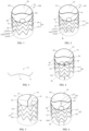
- FIG. 1 is a schematic perspective view of a vascular shunt frame in accordance with a first embodiment of the present disclosure.
- FIG. 2 is a schematic perspective view of a vascular shunt frame provided with a secondary body tube in accordance with a first embodiment of the present disclosure.
- FIG. 3 is a schematic structural view of a shaping component of a vascular shunt frame in accordance with a first embodiment of the present disclosure.
- the present disclosure provides a vascular shunt frame 100, which includes a main body tube 20. At least one end of the main body tube 20 is provided with a sealing covering 50; the sealing covering 50 is provided with a main blood flow opening 52, and an edge of the main blood flow opening 52 is provided with a shaping component.
- the shaping component is disposed on the sealing covering 50 on an edge of the main blood flow opening 52 away from a side of a side wall of the main body tube 20.
- the shaping component is a positioning rod 70 fixed to the sealing covering 50 on the main blood flow opening 52 away from a side of a side wall of the main body tube 20.
- the positioning rod 70 is used for positioning the sealing covering 50, that is, fixing the direction of the sealing covering 50, and increasing the supporting force of the opening edge of the sealing covering.
- the positioning rod 70 is made of a memory alloy wire, preferably a nickel-titanium alloy wire.
- the distal end of the main body tube 20 is provided with the sealing covering 50, i.e., one end of the main body tube 20 farther away from the heart is provided with the sealing covering 50.
- the sealing covering 50 is provided with the main blood flow opening 52.
- the positioning rod 70 extends along an edge of the main blood flow opening 52 connected with a side of a side wall of the main body tube 20 on the sealing covering 50 towards a center of the main body tube 20; two opposite ends of the positioning rod 70 are respectively connected to the side wall of the main body tube 20.
- the vascular shunt frame 100 provided by the present disclosure, by disposing a shaping component on the edge of the sealing covering 50 of the main blood flow opening 54 away from a side of a side wall of the main body tube, locates the sealing covering 50. Therefore, when the main body stent is inserted into the main blood flow opening 52 of the main body tube 20, the shaping component can be closely attached to the outer surface of the main body stent, such that the sealing covering 50 is closely attached to the outer surface of the main body stent, to prevent endoleaks and make it convenient for the main body stent to be inserted into the main blood flow opening 52 of the main body tube 20, thereby increasing the compatibility between the main body stent and the shunt and making the joint between the main body stent and the shunt more stable.
- At least one secondary blood flow opening 54 is disposed on the sealing covering 50; at least one secondary body tube 30 is disposed in the main body tube 20; at least one of the secondary body tubes 30 is connected to at least one of the secondary blood flow openings 54. That is, the secondary body tube 30 is connected with the secondary blood flow opening 54.
- the secondary body tube 30 is formed by tubular partition coverings 31 independently, or formed by the enclosure of semi-tubular partition coverings 31 and the main body tube's tube wall 22.
- a shaping component may be disposed at an edge of at least one secondary blood flow opening 54 of the sealing covering 50, and the shaping component is an annular positioning rod 70 corresponding to the secondary blood flow opening 54.
- the positioning rod 70 at the edge of at least one secondary blood flow opening 54 can fix the branch stent in the secondary body tube 30, i.e., the positioning rod 70 can make the sealing covering 50 in a sealing contact with the outer surface of the branch stent to prevent endoleaks.
- the secondary body tube 30 can extend an anchoring area at the proximal end of the branch stent, further limits the branch stent, and increases the stability of the branch stent after releasing.
- the axial length of the secondary body tube 30 may be less than, greater than or equal to the axial length of the main body tube 20.
- the sealing covering 50 may be provided with the shaping component on the edge of each secondary body tube 30, and the lengths of the secondary body tubes 30 may be the same or different.
- the sealing covering 50 is disposed on the proximal end of the main body tube 20, i.e., the sealing covering 50 is disposed on an end of the main body tube 20 closer to the heart.
- the sealing covering 50 is provided with at least one of the secondary blood flow openings 54 and the main blood flow opening 52, and a proximal end of the secondary body tube 30 is connected with the secondary blood flow opening 54.
- the positioning rod 70 is disposed on the edge of the sealing covering 50 adjacent to a side of the main blood flow opening 52, and two opposite ends of the positioning rod 70 are respectively connected to the proximal end of the main body tube 20; a positioning rod 70 is disposed on an edge of at least one of the secondary blood flow openings 54.
- the distal end and the proximal end of the main body tube 20 are provided with the sealing covering 50; each of the sealing coverings 50 is provided with a main blood flow opening 52 and at least one secondary blood flow opening 54; at least one of the secondary body tubes 30 is disposed in the main body tube 20; two ends of the secondary body tube 30 are respectively connected to the secondary blood flow openings 54 on two sealing coverings 50, i.e., the distal end of the secondary body tube 30 is connected to the secondary blood flow opening 54 on the sealing covering 50 at the distal end of the main body tube 20; the proximal end of the secondary body tube 30 is connected with the secondary blood flow opening 54 on the sealing covering 50 at the proximal end of the main body tube 20.
- the main blood flow openings 52 on the sealing coverings 50 at the proximal end and the distal end of the main body tube 20 are connected.
- the positioning rod 70 is disposed on an edge of each sealing covering 50 adjacent to a side of a corresponding main blood flow opening 52.
- the positioning rod 70 extends along an edge of the sealing covering 50 adjacent to a side of the main blood flow opening 52, and two opposite ends of the positioning rod 70 are connected to the main body tube 20, respectively. Therefore, the positioning rod 70 may be a linear rod, a wavy rod, a curved rod, or other shaped rods.
- the positioningrod 70 is a wave-shaped structure composed of three connected circular arc rods; the positioning rod 70 includes a first circular arc rod 72 located in the middle, and two second circular arc rods 74 connected to two opposite ends of the first circular arc rod 72; the two second circular arc rods 74 have the same structure and are symmetrical along a middle point of the first circular arc rod 72.
- the two second circular arc rods 74 and the first circular arc rod 72 are smoothly connected.
- the first circular arc rod 72 and the two second circular arc rods 74 are an integrated structure, and the positioning rod 70 is formed by bending and shaping a memory alloy wire.
- first circular arc rod 72 and the two second circular arc rods 74 may be in a split structure, that is, the first circular arc rod 72 and the two second circular arc rods 74 are connected together by mechanically pressing or welding.
- a middle portion of the first circular arc rod 72 is bent toward the main blood flow opening 52, and a middle portion of each of the second circular arc rods 74 is bent toward a side away from the main blood flow opening 52, i.e., a middle portion of each of the second circular arc rods 74 is bent toward a side of the secondary blood flow opening 54.
- the diameter of the positioning rod 70 is between 0.10-0.40 mm. In this embodiment, the diameter of the positioning rod 70 is 0.20-0.30 mm.
- the main body tube 20 includes a tubular main body covering 22 and a main body tube support frame 24 fixed to a wall surface of the main body covering 22.
- the secondary body tube 30 is enclosed by a tubular partition covering 31, such that the inner cavity of the main body tube 20 is divided into a main body tube inner cavity 25 and a secondary body tube inner cavity 33.
- the distal end of the main body tube inner cavity 25 is connected with the main blood flow opening 52, and the distal end of the secondary body tube inner cavity 33 is connected with the secondary blood flow opening 54.
- the main body tube 20 is a main structure of the vascular shunt frame 100, and a shape of a transversal end face of the main body tube 20 is a circle or an ellipse that cooperates with a blood vessel.
- the main body tube support frame 24 is stitched on the main body covering 22, and the main body tube support frame 24 is formed by a plurality of annular wave-shaped supporting rods 242 arranged along the axial direction of the main body covering 22.
- Each annular wave-shaped supporting rod 242 may be a high wave supporting rod or a high-low wave supporting rod.
- the high wave supporting rod refers to that the heights of the peaks on the annular wave-shaped supporting rod 242 are the same, and the heights of the valleys are also the same, i.e., the peaks and the valleys are on the same plane, respectively; the high-low wave supporting rod refers to that the heights of the peaks on the annular wave-shaped supporting rod 242 are different, and the heights of the valleys may also be different.
- the main body tube support frame 24 includes a plurality of sinusoidal wave-shaped supporting rods 242. These annular wave-shaped supporting rods 242 are arranged at intervals along the axial direction of the main body covering 22. Each sinusoidal waveform of each of the annular wave-shaped supporting rods 242 includes a peak 2421, a valley 2423, and a connecting rod 2425 connected between the peak 2421 and the valley 2423. Each annular wave-shaped supporting rod 242 is woven by a super-elastic nickel-titanium wire.
- the super-elastic nickel-titanium alloy wire has a selectable wire diameter (i.e., a diameter) ranging from 0.1 mm to 0.6 mm.
- connection sleeve is disposed on each of the annular wave-shaped supporting rods 242, and the connection sleeve connects two opposite ends of the annular wave-shaped supporting rod 242, i.e., the two opposite ends of the annular wave-shaped supporting rod 242 are both received in the connection sleeve, then the two ends of the nickel-titanium wire are fixed inside the connection sleeve by mechanical pressing or welding.
- the annular wave-shaped supporting rod 242 is woven by using a nickel-titanium wire with a diameter of 0.5 mm; the number of the sinusoidal waves is nine; and the vertical height of the annular wave-shaped supporting rod 242 is 6-15 mm.
- the number of the sinusoidal waves may be other numbers, and the vertical height of the annular wave-shaped supporting rod 242 may be any value.
- the main body tube support frame 24 may be a woven mesh structure or a mesh structure formed by cutting.
- the main body covering 22 is made of polyester cloth, PTFE, PET or other polymer materials, and the main body tube support frame 24 is stitched to the main body covering 22 by a suture, i.e., the suture can follow the wave trend of each of the annular wave-shaped supporting rods 242 and accompanies the entire main body tube support frame 24.
- the suture can also stitch each of the annular wave-shaped supporting rods 242 to the main body covering 22 by several non-equally spaced suture knots.
- the diameter of the suture is selected from a range of 0.05 mm-0.25mm.
- the main body support frame 24 is fixedly connected to the main body covering 22 by hot pressing.
- the secondary body tube inner cavity 33 is enclosed by the partition covering 31 independently, and the empty cavity between the partition covering 31 and the main body covering 22 is the main body tube inner cavity 25.
- the diameter of the main body tube inner cavity 25 is larger than the diameter of the secondary body tube inner cavity 33, and the number of the secondary body tubes 30 can be set according to actual needs, generally one to four, preferably one to three; the sealing covering 50 is provided with one to four secondary blood flow openings 54 corresponding to the secondary body tube 30, preferably two to four secondary blood flow openings 54.
- the shapes of the transverse end faces of the main body tube inner cavity 25 and the secondary body tube inner cavity 33 are circular, elliptical, fusiform, or irregularly curved.
- the number of the secondary body tubes 30 is one; the secondary body tube 30 contacts the inner surface of the main body tube 20; and the distal end of the secondary body tube 30 is connected with the secondary blood flow opening 54.
- the secondary blood flow opening 54 faces a middle point of the edge of the blood flow opening 54 adjacent to the main blood flow opening 52.
- the vascular shunt frame 100 includes a circular main body tube inner cavity 25 and a circular secondary body tube inner cavity 33.
- the sealing covering 50 is dispo sed at a distal end of the main body tube 20, and the sealing covering 50 is in a sealed connection with the main body covering 22; the main blood flow opening 52 and the secondary blood flow opening 54 are both disposed on the sealing covering 50; the distal end of the partition covering 31 corresponds to the secondary blood flow opening 54 and is in a sealed connection to the sealing covering 50. That is, the sealing covering 50 connects the main body covering 22 and the partition covering 31 together, and closes a gap between the main body tube 20 and the secondary body tube 30.
- the opening area of the main blood flow opening 52 is smaller than the radial cross-sectional area of the main body covering 22, and the opening area of the secondary blood flow opening 54 is smaller than the opening area of the main blood flow opening 52.
- the opening area of the main blood flow opening 52 may be the same as the opening area of the secondary blood flow opening 54.
- the sealing covering 50 may be disposed along the radial direction or an approximated radial direction of the main body tube 20.
- the sealing covering 50 is located at a distal end of the main body tube 20, and is stitched together with the main body covering 22 and the partition covering 31 by suturing.
- the end face of the distal end of the secondary blood flow opening 54 is lower than the end face of distal end of the main blood flow opening 52, i.e., the sealing covering 50 is recessed toward the secondary blood flow opening 54 such that the sealing covering 50 and the side wall of the main body tube 20 form a bell mouth opening, i.e., the sealing covering 50 is inclined toward the secondary blood flow opening 54.
- the sealing covering 50 is an inclined surface connecting the main blood flow opening 52, the secondary blood flow opening 54, the main body covering 22, and the partition covering 31.
- An angle between the inclined surface and the central axis of the main body tube 20 is 5-80 degrees, preferably 15-60 degrees.
- the sealing covering 50 may be a plane parallel to a radial direction of the main body tube 20, i.e., the sealing covering 50 is a plane perpendicular to a central axis of the main body tube 20.
- the positioning rod 70 may be fixed on the sealing covering 50 by stitching or hot pressing. In this embodiment, the positioning rod 70 is fixed on the edge of the sealing covering 50 by stitching.
- FIG. 4 is a schematic perspective view of a vascular shunt frame in accordance with a second embodiment of the present disclosure.
- the structure of the vascular shunt frame provided in the second embodiment of the present disclosure is similar to that of the first embodiment, and the differences are: in the second embodiment, the sealing covering 50 is provided with two secondary blood flow openings 54; the main body tube inner chamber 20 of the main body tube 20 is provided with two secondary body tubes 30; the distal ends of the two secondary body tubes 30 are connected with the two secondary blood flow openings 54 respectively.
- the two secondary blood flow openings 54 are located on a side away from the main blood flow opening 54; and the outer sides of the two secondary body tubes 30 are in contact with the inner wall of the main body tube inner cavity 25.
- the end faces of the distal ends of the two secondary blood flow openings 54 are lower than the end face of the distal end of the main blood flow opening 52, such that the sealing covering 50 and the side wall of the main body tube 20 form a bell mouth opening.
- a wave-shaped supporting rod 35 is fixed on the partition covering 31 of each secondary body tube 30.
- the wave-shaped supporting rod 35 can increase the supporting strength of the secondary body tube 30 and prevent the connected branch stent from being compressed by the main body stent to result in poor blood flow or even a blockage.
- the wave-shaped supporting rod 35 can be set according to the shape of the partition covering 31. That is, a wave-shaped supporting rod 35 may be fixed on the partition covering 31, or a plurality of wave-shaped supporting rods 35 may be arranged at intervals on the partition covering 31 along the axial direction, and the wave-shaped supporting rod 35 enclose to form the secondary body tube support frame of the partition covering 31.
- the wave-shaped supporting rod 35 may be annular or open-loop. The structure, shape, and material of the wave-shaped supporting rod 35 are similar to the annular wave-shaped supporting rod 242 on the main body tube 20, and details are not described herein again.
- three or more secondary blood flow openings 54 may be disposed on the sealing covering 50; three or more secondary body tubes 30 are disposed in a main body tube inner cavity 25 of the main body tube 20; each secondary blood flow opening 54 is connected with a corresponding secondary body tube 30.
- a woven mesh secondary body tube support frame may be fixed on the partition covering 31.
- the partition covering 31 may also be a semi-tubular structure.
- the partition covering 31 of the semi-tubular structure is stitched on the inner surface of the main body covering 22 to form a semi-circular secondary body tube together with the main body covering 22.
- a side of the main body covering 22 away from the secondary blood flow opening 54 may be cut into a V-shape or a U-shape.
- An edge of the main body covering 22 adjacentto the main body tube inner cavity 25 is provided with a V-shaped or U-shaped positioning rod 70.
- FIG. 5 is a schematic perspective view of a vascular shunt frame in accordance with a third embodiment of the present disclosure.
- the structure of the vascular shunt frame provided in the third embodiment of the present disclosure is similar to that of the second embodiment, and the differences are: in the third embodiment, the sealing covering 50 is parallel to a plane of the radial direction of the main body tube 20, i.e., the sealing covering 50 is perpendicular to a plane of the central axis of the main body tube 20.
- FIG. 6 is a schematic perspective view of a vascular shunt frame in accordance with a fourth embodiment of the present disclosure.
- the structure of the vascular shunt frame provided by the fourth embodiment of the present disclosure is similar to that of the first embodiment, and the differences are: in the fourth embodiment, at least one supporting rod 60 is disposed on the sealing covering 50; one end of the supporting rod 60 is connected to the positioning rod 70; the other end of the supporting rod 60 is connected to an edge of the secondary blood flow opening 54 adjacentto the main blood flow opening 52.
- Both the supporting rod60 and the positioning rod 70 can support the sealing covering 50, to allow the sealing covering 50 to fully spread, and make the sealing covering 50 extend in a direction away from the main blood flow opening 52, to prevent the sealing covering 50 from bending and moving toward the main blood flow opening 52 or the secondary blood flow opening 54 to obstruct the main blood flow opening 52 or the secondary blood flow opening 54; when a main body stent is fitted and connected with the main blood flow opening 52, the positioning rod 70 can be closely attached to the outer surface of the main body stent, and the sealing covering 50 is brought into close contact with the outer surface of the main body stent to prevent blood endoleaks in the main body tube 20.
- the supporting rod 60 includes a rod body 61 and two suturing rings 63 disposed at both ends of the rod body 61.
- One of the suturing rings 63 is connected to the positioning rod 70, and the other of the suturing rings 63 is connected to the edge of the secondary blood flow opening 54.
- the material of the supporting rod 60 is a nickel-titanium wire with a wire diameter of 0.10-0.40 mm, and preferably a wire diameter of 0.20-0.30 mm.
- one of the suturing rings 63 of the supporting rod 60 is fixed to the first circular arc rod 72 of the positioning rod 70, and the other of the suturing rings 63 of the supporting rod 60 is fixed to the edge of the secondary blood flow opening 54 adjacent to the positioning rod 70.
- one of the suturing rings 63 of the supporting rod 60 is fixed to a middle point of the first circular arc rod 72.
- the supporting rod 60 is fixed on the sealing covering 50 of the vascular shunt frame 100 of the present disclosure between the positioning rod 70 and the edge of the secondary blood flow opening 54.
- the supporting rod 60 can fix the direction of the sealing covering 50 such that the sealing covering 50 extends forward, instead of bending or inclining towards the secondary blood flow opening 54 or the main blood flow opening 52, i.e., the sealing covering 50 can be completely spread out without folding such that it does not interfere with the secondary blood flow opening 54 or the main blood flow opening 52, thereby preventing the sealing covering 50 from blocking the secondary blood flow opening 54 or the main blood flow opening 52;
- the supporting rod 60 can also provide guidance for the branch vascular stent inserted on the secondary blood flow opening 54 of the vascular shunt frame 100, i.e., the traction guide wire of the branch vascular stent may slide into the secondary blood flow opening 54 along the smooth sealing covering 50, making it convenient for inserting the branch vascular stent and improving the work efficiency.
- FIG. 7 is a schematic perspective view of a vascular shunt frame in accordance with a fifth embodiment of the present disclosure.
- the structure of the vascular shunt frame provided by the fifth embodiment is similar to that of the fourth embodiment, and the differences are: in the fifth embodiment, the sealing covering 50 is provided with two tangential secondary blood flow openings 54; two secondary body tubes 30 are disposed in the main body tube inner cavity 25 of the main body tube 20; and two distal ends of the two secondary body tubes 30 are connected with the two secondary blood flow openings 54 respectively.
- the two secondary blood flow openings 54 are located on a side away from the main blood flow opening 54, and the outer sides of the two secondary body tubes 30 are attached to the inner wall of the main body tube inner cavity 25.
- the supporting rod 60 is fixed to the sealing covering 50, and is connected between the positioning rod 70 and a tangential point of the two secondary blood flow openings 54.
- the sealing covering 50 is recessed toward the two secondary blood flow openings 54, i.e., the sealing covering 50 is inclined toward the two secondary blood flow openings 54.
- one end of the supporting rod 60 is fixed to the first circular arc rod 72 of the positioning rod 70, and is preferably fixed to a middle point of the first circular arc rod 72.
- the other end of the supporting rod 60 is fixed to between the tangential point of the secondary blood flow openings 54.
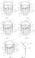
- FIG. 8 is a schematic perspective view of a vascular shunt frame in accordance with a sixth embodiment of the present disclosure.
- the structure of the vascular shunt frame provided by the sixth embodiment of the present disclosure is similar to that of the fifth embodiment, and the differences are: in the sixth embodiment, two sealing blood flow openings 54 are disposed on the sealing covering 50.
- Two sealing rods 60 are fixed to the sealing covering 50 at intervals; the two supporting rods 60 are respectively connected between the edges of the two secondary blood flow openings 54 and the positioning rod 70.
- one end of each supporting rod 60 is fixed on the second circular arc rod 74 of the positioning rod 70, and the other end is fixed on the edge of the corresponding secondary blood flow opening 54.
- the two supporting rods 60 have a shape of an inverted figure eight expressed in Simplified Chinese.
- two supporting rods 60 may be fixed to the sealing covering 50 in parallel with each other, and each supporting rod 60 is connected between an edge of a corresponding secondary blood flow opening 54 and the positioning rod 70.
- FIG. 9 is a schematic perspective view of a vascular shunt frame in accordance with a seventh embodiment of the present disclosure.
- the structure of the vascular shunt frame provided by the seventh embodiment is similar to that of the sixth embodiment, and the differences are: the seventh embodiment adds a supporting rod 60 to the sixth embodiment, that is, three supporting rods 60 are fixed on the sealing covering 50; the three supportingrods 60 are arranged at intervals; one supporting rod 60 in the middle is connected between the tangent point of the two secondary blood flow openings 54 and the first circular arc rod 72 of the positioning rod 70; two supporting rods 60 on both sides are respectively connected between the edges of two secondary blood flow openings 54 and two second circular arc rods 74 of the positioning rod 70.
- both the three supporting rods 60 and the positioning rod 70 together to support the sealing covering 50, it can make the sealing covering 50 more stable and not be folded to interfere with or block the secondary blood flow opening 54 or the main blood flow opening 52, such that the blood flow inside the main body tube 20 and the secondary body tube 30 is more smooth, thereby making it convenient to insert the branch vascular stent.
- one end of the middle supporting rod 60 is connected to the tangential point of the two secondary blood flow openings 54, and the other end is connected to the middle point of the first circular arc rod 72; the two supporting rods 60 on both sides are arranged symmetrically, i.e., the two supporting rods 60 on both sides are symmetrical along a plane defined by the tangential point of the two secondary blood flow openings 54 and the central axis of the main body tube 20.
- FIG. 10 is a schematic perspective view of a vascular shunt frame in accordance with an eighth embodiment of the present disclosure.
- the structure of the vascular shunt frame provided by the eighth embodiment of the present disclosure is similar to that of the sixth embodiment, and the differences are: two supporting rods 60 are added to the sixth embodiment, that is, four supporting rods 50 are fixed to and spaced apart on the sealing covering 50; two out of the four supporting rods 60 are connected between the edge of one secondary blood flow opening 54 and the positioning rod 70; the other two out of the four supporting rods 60 are connected between the edge of the other secondary blood flow opening 54 and the positioning rod 70, i.e., the two supporting rods 60 in the middle are connected between the two secondary blood flow openings 54 and the first circular arc rod 72 of the positioning rod 70; the two supporting rods 60 on both sides are connected between the two secondary blood flow openings 54 and the two second circular arc rods 74 of the positioning rod 70.
- the four supporting rods 60 and the positioning rod 70 together to support the sealing covering 50 it can make the sealing covering 50 more stable, and will not be folded to interfere with or block the secondary blood flow opening 54 or the main blood flow opening 52, such that the blood flow inside the main body tube 20 and the secondary body tube 30 is more smooth, thereby making it convenient to insert the main body stent or the branch vascular stent; and when the main body stent is inserted into the main blood flow opening 52, the positioning rod 70 can be closely attached to the outer surface of the branch vascular stent to prevent endoleaks.
- the four supporting rods 60 are symmetrical along the plane defined by the tangential point of the two secondary blood flow openings 54 and the central axis of the main body tube 20.
- the two supporting rods 60 in the middle are in an inverted "V" shape, and each supporting rod 60 is connected between the middle portion of the first circular arc rod 72 of the positioning rod 70 and the edge of the corresponding secondary blood flow opening 54; the two supporting rods on both sides have a shape of an inverted figure eightexpressed in Simplified Chinese, and each supporting rod 60 is connected between the second circular arc rod 74 of the positioned rod 70 and the edge of the corresponding secondary blood flow opening 54.
- more than four supporting rods 60 may be fixed on the sealing covering 50.
- Apart of the supporting rods 60 is connected to between the edge of one of the secondary blood flow openings 54 and the positioning rod 70 ; another part of the supporting rods 60 is connected between the edge of another of the secondary blood flow openings 54 and the positioning rod 70.
- the sealing covering 50 may be provided with a plurality of the secondary blood flow openings 54.
- the sealing covering 50 may be fixed with a plurality of supporting rods 60 corresponding to the plurality of the secondary blood flow openings 54.
- Each supporting rod 60 is connected to between an edge of a corresponding secondary blood flow opening 54 and the positioning rod 70.
- four supporting rods 60 may be disposed on the sealing covering 50 in parallel and spaced apart.
- FIG. 11 is a schematic perspective of a vascular shunt frame in accordance with a ninth embodiment of the present disclosure.
- the structure of the vascular shunt frame provided by the ninth embodiment is similar to that of the sixth embodiment, and the differences are: the structure of the supporting rod 60a in the ninth embodiment is different from the structure of the supporting rod 60 in the sixth embodiment; as shown in FIG. 11a , the supporting rod 60a includes a first rod body 64 and a second rod body 65 inclinedly connected to one end of the first rod body 64. An angle between the first rod body 64 and the second rod body 65 ranges from 24 to 130 degrees.
- the first rod body 64 of each supporting rod 60a is fixed on the sealing covering 50, and the second rod body 65 is fixed on the side wall of the corresponding secondary body tube 30, i.e., the second rod body 65 is fixed on the partition covering 31 of the corresponding secondary body tube 30; the intersection of the first rod body 64 and the second rod body 65 is located at the intersection of the sealing covering 50 and the side wall of the corresponding secondary body tube 30.
- the inclination angle of the first rod body 64 is the same as that of the sealing covering 50, and the second rod body 65 extends along the axial direction of the corresponding partition covering 31.
- An end of each first rod body 64 away from the corresponding second rod body 65 is fixed on the positioning rod 70.
- an end of each first rod body 64 away from the corresponding second rod body 65 is fixed on the corresponding second circular arc rod 74.
- first rod body 64 and the second rod body 65 are integrated, and the angle between the first rod body 64 and the second rod body 65 is formed by hot pressing and bending.
- the first rod body 64 and the second rod body 65 are respectively fixed on the sealing covering 50 and the partition covering 31 by stitching.
- the first rod body 64 of the supporting rod 60a in this embodiment is fixed on the sealing covering 50, and the end of the first rod body 64 away from the second rod body 65 is fixed on the positioning rod 70.
- the supporting rod 60a and the positioning rod 70 have a supporting effect on the sealing covering 50;
- the second rod body 65 is fixed on the partition covering 31, which can not only support the sealing covering 50, but also locate the corresponding partition covering 31, thereby enhancing the radial supporting force of the secondary body tube 30, and making the sealing covering 50 and the side wall of the main body tube 20 to enclose to form a stable bellmouth opening structure, such that the blood flow in the main body tube 20 and the secondary body tube 30 is more smooth, and it is convenient to insert the branch vascular stent into the main blood flow opening 52 and the secondary blood flow opening 54.
- first rod body 64 and the second rod body 65 may also be a split design, and the connection points of the first rod body 64 and the second rod body 65 are combined by welding, or the first rod body 64 and the second rod body 65 are abutted, and then fixed to the sealing covering 50 and the partition covering 31, respectively.
- the sealing covering 50 may be provided with only one supporting rod 60a.
- the first rod body 64 of the supporting rod 60a is fixed on the sealing covering 50; the end of the first rod body 64 away from the second rod body 65 is fixed on the positioning rod 70; the second rod body 65 is fixed on the tangential point of the two secondary body tubes 30.
- the sealing covering 50 may be provided with only one supporting rod 60a; the sealing covering 50 may be provided with only one secondary blood flow opening 54; the first rod body 64 of the supporting rod 60a may be fixed on the sealing covering 50; the second rod body 65 is fixed on the partition covering 31 of the secondary blood flow opening 54; the intersection of the first rod body 64 and the second rod body 65 is located at the intersection of the sealing covering 50 and the partition covering 31; the first rod body 64 is away from one end of the second rod body 65 and is connected to the positioning rod 70.
- FIG. 11 is a schematic perspective view of a vascular shunt frame in accordance with a tenth embodiment of the present disclosure.
- FIG. 12 is a schematic structural view of a supporting component of the vascular shunt frame in accordance with the tenth embodiment of the present disclosure.
- the structure of the vascular shunt frame provided by the tenth embodiment of the present disclosure is similar to that of the ninth embodiment, and the differences are: in the tenth embodiment, four supporting rods 60a are disposed on the sealing covering 50; the four supporting rods 60a are connected end to end to enclose and form a supporting component in a "W" shape; the middle portion of the "W" shaped supporting component is folded toward the same side.
- the first rod body 64 of each supporting rod 60a is fixed to the sealing covering 50; the second rod body 65 of the supporting rod 60a is fixed to the partition covering 31 of the corresponding secondary body tube 30; the intersection of the first rod body 64 and the second rod body 65 is located at the intersection of the sealing covering 50 and the corresponding partition covering 31. An end of each first rod body 64 away from the corresponding second rod body 65 is fixed on the positioning rod 70.
- the four supporting rods 60a are in an integral symmetrical structure, and the connection points between the first rod bodies 64 of the two supporting rods 60a in the middle are connected to the middle portion of the first circular arc rod 72 of the positioning rod 70; the two second rod bodies 65 are respectively fixed on the partition coverings 31 of the two secondary body tubes 30, such that the two supporting rods 60a in the middle form an inverted "V" shape structure.
- the first rod bodies 64 of the two supporting rods 60a on both sides are respectively connected between the edge of the corresponding secondary blood flow opening 54 and the two circular arc rods 74 of the positioning rod 70; the bottom ends of the two second rod bodies 65 are respectively connected to the bottom ends of the second rod bodies 65 of the two supporting rods 60ain the middle, and are fixed to the partition covering 31 of the corresponding secondary body tube 30, i.e., the two second rod bodies 65 on the partition covering 31 of each secondary body tube 30 enclose to form a "V" shape structure.
- the first rod bodies 64 of the four supporting rods 60a are fixed to the sealing covering 50 at intervals, and are all connected to thepositioningrod 70, thereby having a better support for the sealing covering 50.
- the second rod bodies 65 of the four supporting rods 60a enclose to form two "V" shape support structures, and are respectively fixed to the partition covering 31 of the two secondary body tubes 30, thereby further enhancing the radial supporting force of the secondary body tube 30, such that the sealing covering 50 and the side wall of the main body tube 20 enclose to form a more stable bell mouth opening structure, making the blood flow in the main body tube 20 and the secondary body tube 30 more smooth, and making it convenient to insert the branch vascular stent.
- FIG. 14 is a schematic perspective view of a vascular shunt frame in accordance with an eleventh embodiment of the present disclosure.
- FIG. 15 is a schematic structural view of a radiopaque structure of a vascular shunt frame provided by the eleventh embodiment of the present disclosure.
- the structure of the vascular shunt frame provided in the eleventh embodiment of the present disclosure is similar to that of the first embodiment, and the differences are: in the eleventh embodiment, the secondary body tube 30 is provided with a radiopaque structure 80 at the edge of the secondary blood flow opening 54.
- the radiopaque structure 80 includes a supporting component 82 and a radiopaque component 84.
- the supporting component 82 is a metal ring or metal rod adapted to the shape of the edge of the secondary blood flow opening 54; the radiopaque component 84 is a radiopaque wire continuously or intermittently woundon the metal ring or metal rod.
- the supporting component 82 of the radiopaque structure 80 is made of an alloy doped with a radiopaque material, for example, the nickel-titanium alloy wire made by a nickel-titanium alloy wire containing tantalum; and the diameter of the nickel-titanium alloy wire 84 is 0.10-0.40 mm.
- the radiopaque structure 80 is a radiopaque ring.
- the supporting component 82 is a metal ring made of a memory alloy, such as a nickel-titanium alloy annular structure.
- the metal ring is adapted to the shape of the edge of the secondary blood flow opening 54.
- the radiopaque component 84 is a radiopaque wire continuous or discontinuous wound on the metal ring. Since the annular radiopaque structure 80 has a radiopaque property and is an annular structure, the position of the annular radiopaque structure 80 can be clearly observed by an imaging device during surgery, that is, the annular radiopaque structure 80 can be observed as a circle of the edge of the secondary blood flow 54 rather than scattered radiopaque markers.
- the material for the radiopaque component includes, but is not limited to, gold, platinum, platinum-tungsten, palladium, platinum-iridium, rhodium, tantalum, or alloys or composites of these metals.
- a least a circle of the radiopaque material may be inlaid or pasted on the outer surface of the supporting component 82, such as inlaying a radiopaque metal wire on the supporting component 82, or pasting at least a circle of radiopaque metal wire 84 on the outer surface of the supporting component 82.
- a tantalum wire is wound on the supporting component.
- the annular radiopaque structure 80 are radiopaque markers continuously or intermittently fixed on the edge of the secondary blood flow opening 54 on the sealing covering 50, and the radiopaque markers are stitched, stamped, hot-pressed, mounted or attached to be fixed on the supporting component 82 or are stitched on the sealing covering 50 where the supporting component 82 is located.
- the edge of the main blood flow opening 52 is also provided with an annular radiopaque structure 80.
- the annular radiopaque structure 80 are radiopaque markers continuously or intermittently fixed on the sealing covering 50 on the edge of the main blood flow opening 52.
- the supporting component 82 is a metal ring or metal rod adapted to the shape of the edge of the main blood flow opening 52 or the secondary blood flow opening 54
- the radiopaque component 84 is a radiopaque wire continuously or intermittently wound on the metal ring or metal rod.
- the positioning rod 70 may be made of a memory alloy wire containing a radiopaque material to facilitate the insertion of a branch vascular stent in the main blood flow opening 52.
- the positioning rod 70 is continuously or intermittently wound with a radiopaque wire.
- a radiopaque structure is mounted on or attached to the positioning rod 70.
- a radiopaque metal wire is mounted on the positioning rod 70.
- the distal end or the proximal end of the main body tube 20 may be provided with an annular radiopaque structure 80 at the edge of the main blood flow opening 52.
- At least a circle of a radiopaque wire such as a tantalum, platinum, or palladium wire, can be mounted or attached on the outer surface of the supporting component 82.
- a tantalum wire is wound on the supporting component 82.
- each secondary body tube 30 is also provided with an annular radiopaque structure 80 at the edge of the secondary blood flow opening 54.
- the distal end of the main body tube 20 may be provided with an annular radiopaque structure 80 at the edge of the main blood flow opening 52.
- the radiopaque component 84 is a radiopaque structure mounted on or attached to the outer surface of the metal ring or metal rod.
- the radiopaque component 84 is a radiopaque material fused in the supporting component 82, that is, the radiopaque component 84 is a radiopaque material fused in a metal ring or a metal rod.
- the supporting component 82 is formed by enclosing a tantalum-containing nickel-titanium alloy wire; the diameter of the wire of the supporting component 82 is 0.10-0.40 mm; and the outer diameter of the supporting component 82 is 12-16 mm. Because the supporting component 82 is made of an alloy containing a radiopaque material, the supporting component 82 can be directly used as a radiopaque structure, and there is no need to dispose the radiopaque component 84 on the supporting component 82. During the operation, the position of the supporting component 82 can be clearly observed by an imaging device, and a branch vascular stent can be conveniently and quickly inserted into the secondary blood flow opening 54, making it convenient to use.
- annular radiopaque structure 80 is disposed at an edge at the position of the tube opening of the proximal end of the tube opening of the secondary body tube 30; the design of the annular radiopaque structure 80 is the same as the design of the annular radiopaque structure 80 at the edge of the secondary blood flow opening 54.
- the annular radiopaque structure 80 can also be disposed on the partition covering 31 of the secondary body tube 30.
- a plurality of radiopaque markers are disposed continuous or intermittent on the partition covering 31 along the axial direction from the proximal end to the distal end, and are fixed on the partition covering 31 by suturing, stamping, hot pressing, mounting or attaching.
- the axially arranged radiopaque markers maybe arranged at intervals of one to four in the circumferential direction.
- the axially arranged radiopaque markers can further mark the extension direction of the secondary body tube, so that the surgery operator can complete the operation more quickly during the operation.
- FIG. 16 is a schematic perspective view of a vascular shunt frame in accordance with a twelfth embodiment of the present disclosure.
- the structure of the vascular shunt frame provided in the twelfth embodiment of the present disclosure is similar to that of the fourth embodiment, and the differences are: in the twelfth embodiment, the distal end of the secondary body tube 30 is provided with above-mentioned annular radiopaque structure 80 around the secondary blood flow opening 54; further, the edge of the tube opening of the proximal end of the tube opening of the secondary body tube 30 is also provided with an annular radiopaque structure 80.
- FIG. 17 is a schematic perspective view of a vascular shunt frame in accordance with a thirteenth embodiment of the present disclosure.
- the structure of the vascular shunt frame provided in the thirteenth embodiment of the present disclosure is similar to that of the sixth embodiment, and the differences are: in the thirteenth embodiment, the distal end of each secondary body tube 30 is provided with the above-mentioned annular radiopaque structure 80 around the secondary blood flow opening 54; further, the edge of the tube opening of the proximal end of the tube opening of the secondary body tube 30 is also provided with an annular radiopaque structure 80.
- FIG. 18 is a schematic perspective view of a vascular shunt frame in accordance with a fourteenth embodiment of the present disclosure.
- the structure of the vascular shunt frame provided by the fourteenth embodiment of the present disclosure is similar to that of the seventh embodiment, and the differences are: in the fourteenth embodiment, the distal end of each secondary body tube 30 is provided with the above-mentioned annular radiopaque structure 80 around the secondary blood flowing opening 54; further, the edge of the tube opening of the proximal end of the tube opening of the secondary body tube 30 is also provided with an annular radiopaque structure 80.
- FIG. 19 is a schematic perspective view of a vascular shunt frame in accordance with a fifteenth embodiment of the present disclosure.
- the structure of the vascular shunt frame provided by the fifteenth embodiment of the present disclosure is similar to that of the eighth embodiment, and the differences are: in the fifteenth embodiment, the distal end of each secondary body tube 30 is provided with the above-mentioned annular radiopaque structure 80 around the secondary blood flowing opening 54; further, the edge of the tube opening of the proximal end of the tube opening of the secondary body tube 30 is also provided with an annular radiopaque structure 80.
- FIG. 20 is a schematic perspective view of a vascular shunt frame in accordance with a sixteenth embodiment of the present disclosure.
- the structure of the vascular shunt frame provided by the sixteenth embodiment of the present disclosure is similar to that of the ninth embodiment, and the differences are: in the sixteenth embodiment, the distal end of each secondary body tube 30 is provided with the above-mentioned annular radiopaque structure 80 around the secondary blood flowing opening 54; further, the edge of the tube opening of the proximal end of the tube opening of the secondary body tube 30 is also provided with an annular radiopaque structure 80.
- FIG. 21 is a schematic perspective view of a vascular shunt frame in accordance with a seventeenth embodiment of the present disclosure.
- the structure of the vascular shunt frame provided by the seventeenth embodiment of the present disclosure is similar to that of the tenth embodiment, and the differences are: in the seventeenth embodiment, the distal end of each secondary body tube 30 is provided with the above-mentioned annular radiopaque structure 80 around the secondary blood flowing opening 54; further, the edge of the tube opening of the proximal end of the tube opening of the secondary body tube 30 is also provided with an annular radiopaque structure 80.
- FIG. 22 is a schematic perspective view of the vascular stent in accordance with the eighteenth embodiment of the present disclosure.
- FIG. 23 is a schematic diagram of a vascular stent in one operating state in accordance with an eighteenth embodiment of the present disclosure.
- FIG. 24 is a schematic diagram of a vascular stent in another operating state in accordance with an eighteenth embodiment of the present disclosure.
- the present disclosure also provides a vascular stent, which includes a main body stent 200 and a vascular shunt frame 100.
- the vascular shunt frame 100 includes a main body tube 22.
- At least one end of the main body tube 22 is provided with a sealing covering 50; the sealing covering 50 is provided with a main blood flow opening 52; an edge of a side of the sealing covering 50 adjacent to the main blood flow opening 52 is provided with a shaping component 70; one end of the main body stent 200 passes through the main blood flow opening 52 on the sealing covering 50 and is inserted into the main body tube 20 of the vascular shunt frame 100; the positioning rod 70 is closely attached to the outer surface of the main body stent 200, such that the sealing covering 50 is closely adhered to the outer surface of the main body stent 200.
- the vascular stent further includes a branch stent 300, and one end of the branch stent 300 passes through the secondary blood flow opening 54 on the sealing covering 50 and is inserted into the secondary body tube inner cavity 33 of the secondary body tube 30.
- two sealing body inner cavities 33 and one main body tube inner cavity 25 are disposed on the sealing covering 50 at the distal end of the vascular shunt frame 100.
- the main body stent 200 is inserted into the main body tube inner cavity 25; the positioning rod 70 is closely attached to the outer surface of the main body stent 200; a branch stent 300 is inserted into each secondary body tube inner cavity 33.
- the main body stent 200 includes a connection covering 201 and a connection support frame 202 fixed on the connection covering 201.
- the structure of the main body stent 200 may be an equal-diameter stent-type blood vessel, or a non-equal-diameter stent-type blood vessel.
- the equal-diameter stent-type blood vessel means that the diameters of the main body stent 200 at different positions in the axial direction are the same.
- the non-equal-diameter stent blood vessel means that the diameters of the main body stent 200 at different positions in the axial direction are different.
- the non-equal-diameter stent-type blood vessel is a non-equal-diameter stent composing, from the proximal end to the distal end in sequence, a first tubular body 210, a second tubular body 220, and a third tubular body 230; the diameter of the second tubular body 220 is smaller than that of the first tubularbody 210 and that of the third tubularbody 230.
- a transition portion 221 and a transition portion 222 may be further disposed between the first tubular body 210, the second tubular body 220, and the third tubular body 230. As shown in FIG.
- the main body stent 200 is a non-equal-diameter stent; the diameter of the proximal end of the non-equal-diameter stent is greater than the diameter of the distal end, and the diameter gradually decreases from the proximal end to the distal end.
- the entire support forms a uniform round table structure with smooth transition, to adapt to the morphology of blood vessels with a diameter gradually changing from the proximal end to the distal end.
- connection covering 201 is made of polyester cloth, PTFE, PET or other polymer materials.
- the connection covering 201 of the equal-diameter stent-type vessel is straight, and the connection covering 201 of the non-equal-diameter stent-type vessel is a tubular structure with different axial diameters.
- the main body stent 200 may be a high-low wave stent-type blood vessel or a high-wave stent-type blood vessel. As shown in FIG. 25c , the high-low wave stent-type blood vessel is a partially sutured stent.
- the connection support frame 202 is sutured to the connection covering 201 by a suture.
- the specific suturing method is the same as the suturing method between the main body tube covering 22 and the main body tube support frame 24 of the vascular shunt frame 100 described above, which is not repeated here.
- the embedded branch surface is a high wave array surface of an annular wave-shaped supporting rod, and the center line of the embedded branch corresponds to the center line of the high wave.
- the structure of the branch stent 300 is the same as the structure of the main body stent 200, and details are not described herein again.
- the positioning rod 70 presses the proximal portion of the main body stent 200, such that the tubular body of the main body stent 200 is closely attached to the sealing covering 50 at the distal end of the main body tube 20 to prevent endoleaks.
- the proximal end of the branch stent 300 is released into the secondary blood flow opening 54 of the secondary body tube inner cavity 33 at the distal end of the vascular shunt frame 100; the proximal end of the branch vascular stent 300 is inserted into the secondary body tube inner cavity 33 along the inclined surface of the sealing covering 50, so as to facilitate the insertion of the branch vascular stent 300.
- the secondary body tube inner cavity 33 presses the proximal portion of the branch stent 300 such that the tubular body of the branch stent 300 fits the wall of the secondary body tube inner cavity 33 to prevent endoleaks. Because a radiopaque structure 80 is disposed at both the main blood flow opening 52 of the main body tube inner cavity 25 of the vascular shunt frame 100 and the secondary blood flow opening 54 of the secondary body tube inner cavity 33, the main body stent 200 and the branch vascular stent 300 can be easily inserted.
- the vascular stent can be used for the treatment of thoracic aortic aneury sm or thoracic aortic dissection disease, and is particularly suitable for the treatment of thoracic aortic aneurysm or thoracic aortic dissection disease involving the ascending aorta or aortic arch. As shown in FIG.
- the delivery device when releasing, one pushes the delivery device along the super-hard guide wire to push the pre-installed vascular shunt frame 100 to the position of the thoracic aortic dissection; one locates by the development ring at the front end of the sheath tube and the radiopaque structure 80 at the distal end of the vascular shunt frame 100, and releases the vascular shunt frame 100 by operating the handle of the delivery device; then one releases the main body stent 200 according to the same steps, such that the proximal end of the main body stent 200 is inserted into the main body tube inner cavity 25 of the vascular shunt frame 100; after expansion, the proximal end of the main body stent 200 is stuck by the positioning rod 70 and the main blood flow opening 52 to form a tight cooperation, thereby preventing the main body stent 200 from detaching from the vascular shunt frame 100. Finally, the same steps are followed to release the branch stent 300.
- the main body stent 200 may further is provided with a blood flow opening 205, and a branch vascular stent is inserted into the blood flow opening 205.
- some of the main body stents 200 or the branch stents 300, from the distal end to the proximal end in sequence, are non-equal-height annular wave-shaped supporting rods.
- One to four peaks and/or valleys not sutured to the covering are disposed at the distal end or the proximal end of the stent graft of the annular stents; the peaks and/or valleys are bare stents for convenience of assembly.
- the number of each annular stent is set according to the axial length of the stent graft.
Landscapes
- Health & Medical Sciences (AREA)
- Engineering & Computer Science (AREA)
- Biomedical Technology (AREA)
- Heart & Thoracic Surgery (AREA)
- Public Health (AREA)
- Transplantation (AREA)
- Cardiology (AREA)
- Veterinary Medicine (AREA)
- Oral & Maxillofacial Surgery (AREA)
- Vascular Medicine (AREA)
- Life Sciences & Earth Sciences (AREA)
- Animal Behavior & Ethology (AREA)
- General Health & Medical Sciences (AREA)
- Gastroenterology & Hepatology (AREA)
- Pulmonology (AREA)
- Physics & Mathematics (AREA)
- Optics & Photonics (AREA)
- Prostheses (AREA)
Claims (20)
- Gefäß-Shunt-Gerüst (100) mit verbesserter Apposition, umfassend einen Hauptkörperschlauch (20),
wobei mindestens ein Ende des Hauptkörperschlauchs (20) mit einer Abdichtungsabdeckung (50) versehen ist; wobei die Abdichtungsabdeckung (50) mit einer Hauptblutflussöffnung (52) versehen ist und ein Rand der Hauptblutflussöffnung (52) mit einer Formungskomponente versehen ist; wobei die Formungskomponente an der Abdichtungsabdeckung (50) an einem Rand der Hauptblutflussöffnung (52) von einer Seite einer Seitenwand des Hauptkörperschlauchs (20) weg angeordnet ist; wobei zwei entgegengesetzte Enden der Formungskomponente an die Seitenwand des Hauptkörperschlauchs (20) gekoppelt sind; so dass die Hauptblutflussöffnung (52) von der Formungskomponente und der Seitenwand des Hauptkörperschlauchs (20) umgeben ist. - Gefäß-Shunt-Gerüst (100) nach Anspruch 1, wobei die Formungskomponente zur Positionierung der Abdichtungsabdeckung (50) verwendet wird und aus einem Gedächtnislegierungsdraht hergestellt ist.
- Gefäß-Shunt-Gerüst (100) nach Anspruch 1, wobei die Formungskomponente ein Positionierungsstab (70) ist und der Positionierungsstab (70) an der Abdichtungsabdeckung (50) an einem Rand der Hauptblutflussöffnung (52) von einer Seite einer Seitenwand des Hauptkörperschlauchs (20) weg befestigt ist.
- Gefäß-Shunt-Gerüst (100) nach Anspruch 3, wobei der Positionierungsstab (70) sich entlang eines Rands der Hauptblutflussöffnung (52) verbunden mit einer Seite einer Seitenwand des Hauptkörperschlauchs (20) an der Abdichtungsabdeckung (50) zu einer Mitte des Hauptkörperschlauchs (20) erstreckt; wobei zwei entgegengesetzte Enden des Positionierungsstabs (70) jeweils mit der Seitenwand des Hauptkörperschlauchs (20) verbunden sind.
- Gefäß-Shunt-Gerüst (100) nach Anspruch 3, wobei der Positionierungsstab (70) ein gerader Stab, ein gewellter Stab oder ein gebogener Stab ist.
- Gefäß-Shunt-Gerüst (100) nach Anspruch 3, wobei der Positionierungsstab (70) sich aus drei verbundenen kreisförmigen Bogenstab zusammensetzt; wobei der Positionierungsstab (70) einen ersten kreisförmigen Bogenstab (72), der sich in der Mitte befindet, und zwei zweite kreisförmige Bogenstäbe (74), die mit zwei entgegengesetzten Enden des ersten kreisförmigen Bogenstabs (72) verbunden sind, umfasst; wobei die zwei zweiten kreisförmigen Bogenstäbe (74) entlang eines Mittelpunkts des ersten kreisförmigen Bogenstabs (72) symmetrisch sind.
- Gefäß-Shunt-Gerüst (100) nach Anspruch 6, wobei ein Mittelabschnitt des ersten kreisförmigen Bogenstabs (72) zu der Hauptblutflussöffnung (52) gebogen ist und ein Mittelabschnitt jedes von den zweiten kreisförmigen Bogenstäben (74) zu einer Seite von der Hauptblutflussöffnung (52) weg gebogen ist.
- Gefäß-Shunt-Gerüst (100) nach einem der Ansprüche 1 bis 7, wobei mindestens eine sekundäre Blutflussöffnung (54) an der Abdichtungsabdeckung (50) angeordnet ist; wobei mindestens ein sekundärer Körperschlauch (30) in dem Hauptkörperschlauch (20) angeordnet ist; wobei mindestens einer von den sekundären Körperschläuchen (30) mit mindestens einer von den sekundären Blutflussöffnungen verbunden ist.
- Gefäß-Shunt-Gerüst (100) nach Anspruch 8, wobei die Abdichtungsabdeckung (50) mit mindestens einer Stützkomponente versehen ist und mindestens eine von den Stützkomponenten zwischen der Formungskomponente und einem Rand mindestens einer von den sekundären Blutflussöffnungen verbunden ist.
- Gefäß-Shunt-Gerüst (100) nach Anspruch 9, wobei mindestens eine von den Stützkomponenten ein Stützstab (60, 60a) ist, der an der Abdichtungsabdeckung (50) befestigt ist; wobei ein Ende des Stützstabs (60, 60a) mit der Formungskomponente verbunden ist und das andere Ende des Stützstabs (60, 60a) mit einem Rand mindestens einer von den sekundären Blutflussöffnungen angrenzend an die Formungskomponente verbunden ist.
- Gefäß-Shunt-Gerüst (100) nach Anspruch 10, wobei die Abdichtungsabdeckung (50) mit zwei tangentialen sekundären Blutflussöffnungen (54) versehen ist und mindestens einer von den Stützstäben (60, 60a) zwischen der Formungskomponente und einem Tangentialpunkt der zwei sekundären Blutflussöffnungen verbunden ist.
- Gefäß-Shunt-Gerüst (100) nach Anspruch 10, wobei zwei Stützstäbe (60, 60a) an der Abdichtungsabdeckung (50) stationär beabstandet sind und die zwei Stützstäbe (60, 60a) jeweils zwischen einem Rand der sekundären Blutflussöffnung (54) und der Formungskomponente verbunden sind.
- Gefäß-Shunt-Gerüst (100) nach Anspruch 10, wobei drei Stützstäbe (60, 60a) an der Abdichtungsabdeckung (50) stationär beabstandet sind; wobei ein Stützstab (60, 60a) in der Mitte zwischen der sekundären Blutflussöffnung (54) und dem Mittelabschnitt der Formungskomponente verbunden ist; wobei zwei Stützstäbe (60, 60a) auf beiden Seiten jeweils zwischen dem Rand der sekundären Blutflussöffnung (54) und zwei entgegengesetzten Enden der Formungskomponente verbunden sind.
- Gefäß-Shunt-Gerüst (100) nach Anspruch 10, wobei vier Stützstäbe (60, 60a) an der Abdichtungsabdeckung (50) stationär beabstandet sind; wobei zwei Stützstäbe (60, 60a) in der Mitte zwischen der sekundären Blutflussöffnung (54) und dem Mittelabschnitt der Formungskomponente verbunden sind; wobei zwei Stützstäbe (60, 60a) auf beiden Seiten jeweils zwischen einem Rand der sekundären Blutflussöffnung (54) und zwei entgegengesetzten Enden der Formungskomponente verbunden sind.
- Gefäß-Shunt-Gerüst (100) nach Anspruch 10, wobei mindestens ein Stützstab (60, 60a) einen ersten Stabkörper (64) und einen zweiten Stabkörper (65), der mit einem Ende des ersten Stabkörpers (64) schräg verbunden ist, umfasst; wobei der erste Stabkörper (64) an der Abdichtungsabdeckung (50) befestigt ist; wobei der zweite Stabkörper (65) an einer Seitenwand mindestens einem von den sekundären Körperschläuchen (30) befestigt ist; wobei ein Kreuzungspunkt zwischen dem ersten Stabkörper (64) und dem zweiten Stabkörper (65) sich an einem Kreuzungspunkt zwischen der Abdichtungsabdeckung (50) und der Seitenwand des sekundären Körperschlauchs (30) befindet; wobei ein Ende des ersten Stabkörpers (64) von dem zweiten Stabkörper (65) weg mit der Formungskomponente verbunden ist.
- Gefäß-Shunt-Gerüst (100) nach Anspruch 9, wobei mindestens eine Endfläche eines distalen Endes der sekundären Blutflussöffnung (54) niedrige als eine Endfläche eines distalen Endes der Hauptblutflussöffnung (52) ist; wobei die Abdichtungsabdeckung (50) zu mindestens einer von den sekundären Blutflussöffnungen zurückgesetzt ist, so dass die Abdichtungsabdeckung (50) und die Seitenwand des Hauptkörperschlauchs (20) eine Schalltrichteröffnung bilden.
- Gefäß-Shunt-Gerüst (100) nach Anspruch 8, wobei ein Rand mindestens einer von der sekundären Blutflussöffnung (54) und/oder der Hauptblutflussöffnung (52) mit einer röntgendichten Struktur (80) versehen ist, wobei es sich bei der röntgendichten Struktur (80) um röntgendichte Marker handelt, die durchgehend oder intermittierend an einem Rand einer Abdeckung an einer beliebigen sekundären Blutflussöffnung (54) oder der Hauptblutflussöffnung (52) befestigt sind.
- Gefäß-Shunt-Gerüst (100) nach Anspruch 17, wobei die röntgendichte Struktur (80) eine Stützkomponente (82) und eine röntgendichte Komponente (84) umfasst und die Stützkomponente (82) ein Metallring oder ein Metallstab ist, der zu einer Form eines Rands der Hauptblutflussöffnung (52) oder der sekundären Blutflussöffnung angepasst ist, wobei die röntgendichte Komponente (84) aus der Gruppe bestehend aus einem röntgendichten Draht, der durchgehend oder intermittierend um den Metallring oder den Metallstab gewickelt ist; und einem röntgendichten Marker, der in einen Umfang oder eine Oberfläche eines Metallstabs eingelegt oder darauf geklebt ist; und einem röntgendichten Material, das in den Metallring oder den Metallstab verschmolzen ist, ausgewählt ist.
- Gefäß-Stent, umfassend einen Hauptkörper-Stent (200), wobei der Gefäß-Stent weiterhin ein Gefäß-Shunt-Gerüst (100) nach einem der Ansprüche 1 bis 7 und 9 bis 18 umfasst; wobei ein Ende des Hauptkörper-Stents (200) durch die Hauptblutflussöffnung (52) an der Abdichtungsabdeckung (50) verläuft und in den Hauptkörperschlauch (20) des Gefäß-Shunt-Gerüsts (100) eingeführt ist; wobei die Formungskomponente den Hauptkörper-Stent (50) positioniert, so dass die Abdichtungsabdeckung (50) nahe an einer äußeren Oberfläche des Hauptkörper-Stents (200) haftet.
- Gefäß-Stent nach Anspruch 19, wobei eine Astblutflussöffnung (205) an dem Hauptkörper-Stent (200) angeordnet sein kann und der Gefäß-Stent weiterhin einen Ast-Stent (300) umfasst und ein Ende des Ast-Stents durch die sekundäre Blutflussöffnung (54) an der Abdichtungsabdeckung (50) verläuft und in den sekundären Körperschlauch (30) des Gefäß-Shunt-Gerüsts (100) eingeführt ist.
Applications Claiming Priority (4)
| Application Number | Priority Date | Filing Date | Title |
|---|---|---|---|
| CN201711192775 | 2017-11-24 | ||
| CN201711192781 | 2017-11-24 | ||
| CN201810899831.5A CN109833123B (zh) | 2017-11-24 | 2018-08-08 | 改进贴壁性的血管分流架及血管支架 |
| PCT/CN2018/116545 WO2019101078A1 (zh) | 2017-11-24 | 2018-11-20 | 改进贴壁性的血管分流架及血管支架 |
Publications (3)
| Publication Number | Publication Date |
|---|---|
| EP3714845A1 EP3714845A1 (de) | 2020-09-30 |
| EP3714845A4 EP3714845A4 (de) | 2020-12-30 |
| EP3714845B1 true EP3714845B1 (de) | 2024-01-03 |
Family
ID=66882978
Family Applications (1)
| Application Number | Title | Priority Date | Filing Date |
|---|---|---|---|
| EP18882101.1A Active EP3714845B1 (de) | 2017-11-24 | 2018-11-20 | Shunt-katheter zur verbesserten verankerung |
Country Status (3)
| Country | Link |
|---|---|
| US (1) | US11633296B2 (de) |
| EP (1) | EP3714845B1 (de) |
| CN (6) | CN109833116B (de) |
Families Citing this family (22)
| Publication number | Priority date | Publication date | Assignee | Title |
|---|---|---|---|---|
| CN109833116B (zh) * | 2017-11-24 | 2024-06-07 | 杭州唯强医疗科技有限公司 | 增强稳定性的血管分流架及血管支架 |
| CN109966034B (zh) * | 2017-12-27 | 2021-08-17 | 先健科技(深圳)有限公司 | 覆膜支架 |
| WO2020108546A1 (zh) * | 2018-11-28 | 2020-06-04 | 杭州唯强医疗科技有限公司 | 改进显影性能的血管支架及其内嵌分支支架 |
| CN110420074B (zh) * | 2019-06-27 | 2022-04-05 | 深圳市先健畅通医疗有限公司 | 覆膜支架 |
| WO2020259709A1 (zh) * | 2019-06-27 | 2020-12-30 | 深圳市先健畅通医疗有限公司 | 覆膜支架 |
| CN110420075B (zh) * | 2019-06-27 | 2022-04-05 | 深圳市先健畅通医疗有限公司 | 覆膜支架 |
| CN112618122B (zh) * | 2019-09-24 | 2024-04-19 | 杭州唯强医疗科技有限公司 | 血管支架 |
| US11324582B2 (en) * | 2019-09-27 | 2022-05-10 | Medtronic Vascular, Inc. | Docking graft for placement of parallel distally extending grafts assembly and method |
| EP4044966B1 (de) * | 2019-10-15 | 2026-04-08 | Merit Medical Systems, Inc. | Endovaskuläre prothese mit selektiv zu öffnendem innenkanal |
| CN113040975B (zh) * | 2019-12-27 | 2022-08-12 | 深圳市先健畅通医疗有限公司 | 管腔支架 |
| CN113116610B (zh) * | 2019-12-30 | 2023-01-03 | 先健科技(深圳)有限公司 | 显影结构和血管支架 |
| CN113057774B (zh) * | 2019-12-30 | 2023-03-21 | 先健科技(深圳)有限公司 | 显影结构、植入器械和血管支架 |
| CN113693778B (zh) * | 2020-05-06 | 2025-09-12 | 杭州唯强医疗科技有限公司 | 血管分流架及血管支架 |
| EP4147673A4 (de) * | 2020-05-06 | 2024-05-22 | Hangzhou Endonom Medtech Co., Ltd | Vaskulärer stent mit geteiltem fluss und vaskulärer stent |
| WO2021223621A1 (zh) * | 2020-05-06 | 2021-11-11 | 杭州唯强医疗科技有限公司 | 血管分流架及血管支架 |
| CN113693777B (zh) * | 2020-05-06 | 2025-09-12 | 杭州唯强医疗科技有限公司 | 血管分流架及血管支架 |
| CN112022436B (zh) * | 2020-10-13 | 2025-04-25 | 杭州唯强医疗科技有限公司 | 覆膜支架 |
| IL302050A (en) * | 2020-10-13 | 2023-06-01 | Hangzhou Endonom Medtech Co Ltd | Covered stent |
| WO2022143097A1 (zh) * | 2020-12-31 | 2022-07-07 | 杭州唯强医疗科技有限公司 | 覆膜支架 |
| WO2023124903A1 (zh) * | 2021-12-31 | 2023-07-06 | 先健科技(深圳)有限公司 | 管腔支架 |
| CN115252216A (zh) * | 2022-08-01 | 2022-11-01 | 复旦大学附属中山医院 | 一种模块化主动脉弓上三分支覆膜支架主体 |
| CN120203866B (zh) * | 2023-12-27 | 2026-02-17 | 先健科技(深圳)有限公司 | 覆膜支架及支架输送系统 |
Family Cites Families (40)
| Publication number | Priority date | Publication date | Assignee | Title |
|---|---|---|---|---|
| US6306164B1 (en) * | 1997-09-05 | 2001-10-23 | C. R. Bard, Inc. | Short body endoprosthesis |
| US6585756B1 (en) | 1999-05-14 | 2003-07-01 | Ernst P. Strecker | Implantable lumen prosthesis |
| US8092511B2 (en) | 2000-03-03 | 2012-01-10 | Endovascular Technologies, Inc. | Modular stent-graft for endovascular repair of aortic arch aneurysms and dissections |
| US8870946B1 (en) * | 2000-12-11 | 2014-10-28 | W.L. Gore & Associates, Inc. | Method of deploying a bifurcated side-access intravascular stent graft |
| US6929661B2 (en) | 2001-11-28 | 2005-08-16 | Aptus Endosystems, Inc. | Multi-lumen prosthesis systems and methods |
| US7044962B2 (en) * | 2002-06-25 | 2006-05-16 | Scimed Life Systems, Inc. | Implantable prosthesis with displaceable skirt |
| DE602004015486D1 (de) * | 2003-10-10 | 2008-09-11 | Cook Inc | Dehnbares prothesenfenster |
| US7828837B2 (en) | 2005-02-17 | 2010-11-09 | Khoury Medical Devices, LLC. | Vascular endograft |
| EP2051663B1 (de) * | 2006-08-18 | 2009-11-18 | William, a Cook Australia Pty. Ltd. | Stent-implantat |
| CN201058061Y (zh) * | 2007-06-12 | 2008-05-14 | 中国人民解放军第二军医大学 | 主动脉弓部带分支的血管腔内移植物 |
| US8021413B2 (en) | 2007-12-27 | 2011-09-20 | Cook Medical Technologies Llc | Low profile medical device |
| GB0803302D0 (en) | 2008-02-22 | 2008-04-02 | Barts & London Nhs Trust | Blood vessel prosthesis and delivery apparatus |
| CN101579265B (zh) * | 2008-05-12 | 2011-03-30 | 先健科技(深圳)有限公司 | 主动脉弓支架型血管 |
| CN201230914Y (zh) * | 2008-05-12 | 2009-05-06 | 先健科技(深圳)有限公司 | 主动脉弓支架型血管 |
| CN101836911A (zh) * | 2009-03-18 | 2010-09-22 | 微创医疗器械(上海)有限公司 | 侧支型覆膜支架 |
| CN102068331B (zh) * | 2010-04-20 | 2013-08-07 | 上海微创医疗器械(集团)有限公司 | 一种分叉血管支架 |
| US20110270379A1 (en) * | 2010-04-29 | 2011-11-03 | Medtronic Vascular, Inc. | Mobile External Coupling for Branch Vessel Connection |
| AU2010210022B1 (en) * | 2010-08-05 | 2011-09-08 | Cook Incorporated | Stent graft having a marker and a reinforcing and marker ring |
| CA2748206C (en) * | 2010-08-21 | 2015-06-23 | Blayne A. Roeder | Prosthesis having pivoting fenestration |
| CN102429750B (zh) * | 2011-08-15 | 2015-05-20 | 上海微创医疗器械(集团)有限公司 | 改进显影性能的血管支架及增强血管支架显影性能的方法 |
| US20140135905A1 (en) | 2012-11-12 | 2014-05-15 | Yen-Ni Hung | Aortic stent |
| US10265202B2 (en) | 2013-03-14 | 2019-04-23 | Cook Medical Technologies Llc | Prosthesis having an everting pivoting fenestration |
| US9486306B2 (en) * | 2013-04-02 | 2016-11-08 | Tendyne Holdings, Inc. | Inflatable annular sealing device for prosthetic mitral valve |
| US20170319359A1 (en) * | 2013-04-16 | 2017-11-09 | Manish Mehta | Endovascular docking apparatus and method |
| US10105245B2 (en) | 2013-08-23 | 2018-10-23 | Cook Medical Technologies Llc | Stent graft assembly for treating branched vessels |
| CN106456314A (zh) | 2014-01-28 | 2017-02-22 | 美国桑福德医疗集团 | 肾旁和胸弓形支架型移植件及其使用方法 |
| US9980832B2 (en) * | 2014-01-28 | 2018-05-29 | Sanford Health | Pararenal and thoracic arch stent graft and methods for use |
| EP2915509A1 (de) | 2014-03-05 | 2015-09-09 | Cardiatis S.A. | Stentanordnung zur Reparatur eines verzweigten thorakoabdominellen Aneurysmas |
| CN105213076A (zh) * | 2014-06-12 | 2016-01-06 | 微创心脉医疗科技(上海)有限公司 | 一种人造瘤颈及其制备方法 |
| ES2969694T3 (es) | 2014-09-23 | 2024-05-22 | Bolton Medical Inc | Dispositivos de reparación vascular |
| AU2016238336A1 (en) * | 2015-03-25 | 2017-08-17 | Sanford Health | Pararenal and thoracic arch stent graft and methods for use |
| US20170000630A1 (en) | 2015-06-30 | 2017-01-05 | University Of South Florida | Universal Multi-Branch Endograft |
| CN205924245U (zh) * | 2016-03-05 | 2017-02-08 | 郭伟 | 一种易于插接分支的支架型血管 |
| CN105662649B (zh) * | 2016-03-05 | 2017-09-01 | 郭伟 | 一种易于插接分支的支架型血管 |
| CN105662650B (zh) * | 2016-03-21 | 2018-08-14 | 中国医科大学附属第一医院 | 一体式覆膜分支血管支架及其输送系统 |
| CN106109056B (zh) * | 2016-07-22 | 2018-02-13 | 有研医疗器械(北京)有限公司 | 一种多腔型覆膜支架及其使用方法 |
| CN106236339B (zh) * | 2016-07-22 | 2018-06-01 | 江苏大学 | 一种适用于分叉血管主支的锥形血管支架 |
| CN106580518B (zh) * | 2016-12-20 | 2018-11-16 | 有研医疗器械(北京)有限公司 | 一种组合式腹主动脉覆膜支架系统及其使用方法 |
| CN109833116B (zh) * | 2017-11-24 | 2024-06-07 | 杭州唯强医疗科技有限公司 | 增强稳定性的血管分流架及血管支架 |
| US11166832B2 (en) * | 2018-06-19 | 2021-11-09 | Medtronic Vascular, Inc. | Re-location of main body bypass branch on multi-branched stent graft |
-
2018
- 2018-08-08 CN CN201810899833.4A patent/CN109833116B/zh active Active
- 2018-08-08 CN CN201821275672.3U patent/CN209474865U/zh not_active Withdrawn - After Issue
- 2018-08-08 CN CN201810899622.0A patent/CN109833124B/zh active Active
- 2018-08-08 CN CN201821275038.XU patent/CN209474879U/zh not_active Withdrawn - After Issue
- 2018-08-08 CN CN201821275371.0U patent/CN209236478U/zh active Active
- 2018-08-08 CN CN201810899831.5A patent/CN109833123B/zh active Active
- 2018-11-20 US US16/765,002 patent/US11633296B2/en active Active
- 2018-11-20 EP EP18882101.1A patent/EP3714845B1/de active Active
Also Published As
| Publication number | Publication date |
|---|---|
| CN109833116A (zh) | 2019-06-04 |
| CN209474865U (zh) | 2019-10-11 |
| US11633296B2 (en) | 2023-04-25 |
| CN109833124A (zh) | 2019-06-04 |
| CN109833123A (zh) | 2019-06-04 |
| EP3714845A1 (de) | 2020-09-30 |
| US20200315820A1 (en) | 2020-10-08 |
| CN109833124B (zh) | 2024-07-19 |
| CN209236478U (zh) | 2019-08-13 |
| EP3714845A4 (de) | 2020-12-30 |
| CN209474879U (zh) | 2019-10-11 |
| CN109833116B (zh) | 2024-06-07 |
| CN109833123B (zh) | 2021-04-20 |
Similar Documents
| Publication | Publication Date | Title |
|---|---|---|
| US11633296B2 (en) | Vascular shunt frame and vascular stent with improved apposition | |
| EP3714838B1 (de) | Mit mehreren kammern bedeckter stent | |
| US11969171B2 (en) | Systems and methods for treating aneurysms | |
| EP2409670B1 (de) | Prothese | |
| JP2007503923A (ja) | ステントグラフト、ステントグラフトデリバリー(送入)システムおよびキット、およびステントグラフトを留置する方法 | |
| JP2009106763A (ja) | 多管腔補綴具システムおよび方法 | |
| EP2749253B1 (de) | Endoluminale Prothese mit modularen Zweigen | |
| JP2013543416A (ja) | ステントグラフトシステム | |
| CN111227991B (zh) | 血管支架及其内嵌分支支架 | |
| CN111227990B (zh) | 改进显影性能的血管支架及其内嵌分支支架 | |
| CN212996885U (zh) | 血管分流架及血管支架 | |
| CN209827101U (zh) | 血管支架及其内嵌分支支架 | |
| CN209966658U (zh) | 改进显影性能的血管支架及其内嵌分支支架 | |
| US20230248506A1 (en) | Stent-Graft System | |
| CN110916860A (zh) | 一种用于封闭分叉动脉瘤的支架装置 | |
| WO2020108546A1 (zh) | 改进显影性能的血管支架及其内嵌分支支架 | |
| CN113693777B (zh) | 血管分流架及血管支架 | |
| WO2019101079A1 (zh) | 改进显影可视性的血管分流架及血管支架 | |
| CN213993852U (zh) | 血管分流架及血管支架 | |
| WO2019101078A1 (zh) | 改进贴壁性的血管分流架及血管支架 | |
| US20230056469A1 (en) | Vascular Shunt Stent and Vascular Stent | |
| WO2021223621A1 (zh) | 血管分流架及血管支架 | |
| WO2019101077A1 (zh) | 增强稳定性的血管分流架及血管支架 | |
| CN113693778B (zh) | 血管分流架及血管支架 | |
| WO2020108547A1 (zh) | 血管支架及其内嵌分支支架 |
Legal Events
| Date | Code | Title | Description |
|---|---|---|---|
| STAA | Information on the status of an ep patent application or granted ep patent |
Free format text: STATUS: THE INTERNATIONAL PUBLICATION HAS BEEN MADE |
|
| PUAI | Public reference made under article 153(3) epc to a published international application that has entered the european phase |
Free format text: ORIGINAL CODE: 0009012 |
|
| STAA | Information on the status of an ep patent application or granted ep patent |
Free format text: STATUS: REQUEST FOR EXAMINATION WAS MADE |
|
| 17P | Request for examination filed |
Effective date: 20200601 |
|
| AK | Designated contracting states |
Kind code of ref document: A1 Designated state(s): AL AT BE BG CH CY CZ DE DK EE ES FI FR GB GR HR HU IE IS IT LI LT LU LV MC MK MT NL NO PL PT RO RS SE SI SK SM TR |
|
| AX | Request for extension of the european patent |
Extension state: BA ME |
|
| A4 | Supplementary search report drawn up and despatched |
Effective date: 20201201 |
|
| RIC1 | Information provided on ipc code assigned before grant |
Ipc: A61F 2/07 20130101ALI20201126BHEP Ipc: A61F 2/82 20130101AFI20201126BHEP |
|
| DAV | Request for validation of the european patent (deleted) | ||
| DAX | Request for extension of the european patent (deleted) | ||
| GRAP | Despatch of communication of intention to grant a patent |
Free format text: ORIGINAL CODE: EPIDOSNIGR1 |
|
| STAA | Information on the status of an ep patent application or granted ep patent |
Free format text: STATUS: GRANT OF PATENT IS INTENDED |
|
| INTG | Intention to grant announced |
Effective date: 20230725 |
|
| GRAS | Grant fee paid |
Free format text: ORIGINAL CODE: EPIDOSNIGR3 |
|
| GRAA | (expected) grant |
Free format text: ORIGINAL CODE: 0009210 |
|
| STAA | Information on the status of an ep patent application or granted ep patent |
Free format text: STATUS: THE PATENT HAS BEEN GRANTED |
|
| AK | Designated contracting states |
Kind code of ref document: B1 Designated state(s): AL AT BE BG CH CY CZ DE DK EE ES FI FR GB GR HR HU IE IS IT LI LT LU LV MC MK MT NL NO PL PT RO RS SE SI SK SM TR |
|
| REG | Reference to a national code |
Ref country code: GB Ref legal event code: FG4D |
|
| REG | Reference to a national code |
Ref country code: CH Ref legal event code: EP |
|
| REG | Reference to a national code |
Ref country code: DE Ref legal event code: R096 Ref document number: 602018063781 Country of ref document: DE |
|
| REG | Reference to a national code |
Ref country code: IE Ref legal event code: FG4D |
|
| REG | Reference to a national code |
Ref country code: LT Ref legal event code: MG9D |
|
| PG25 | Lapsed in a contracting state [announced via postgrant information from national office to epo] |
Ref country code: ES Free format text: LAPSE BECAUSE OF FAILURE TO SUBMIT A TRANSLATION OF THE DESCRIPTION OR TO PAY THE FEE WITHIN THE PRESCRIBED TIME-LIMIT Effective date: 20240103 |
|
| PG25 | Lapsed in a contracting state [announced via postgrant information from national office to epo] |
Ref country code: ES Free format text: LAPSE BECAUSE OF FAILURE TO SUBMIT A TRANSLATION OF THE DESCRIPTION OR TO PAY THE FEE WITHIN THE PRESCRIBED TIME-LIMIT Effective date: 20240103 |
|
| REG | Reference to a national code |
Ref country code: NL Ref legal event code: MP Effective date: 20240103 |
|
| REG | Reference to a national code |
Ref country code: AT Ref legal event code: MK05 Ref document number: 1646062 Country of ref document: AT Kind code of ref document: T Effective date: 20240103 |
|
| PG25 | Lapsed in a contracting state [announced via postgrant information from national office to epo] |
Ref country code: NL Free format text: LAPSE BECAUSE OF FAILURE TO SUBMIT A TRANSLATION OF THE DESCRIPTION OR TO PAY THE FEE WITHIN THE PRESCRIBED TIME-LIMIT Effective date: 20240103 |
|
| PG25 | Lapsed in a contracting state [announced via postgrant information from national office to epo] |
Ref country code: NL Free format text: LAPSE BECAUSE OF FAILURE TO SUBMIT A TRANSLATION OF THE DESCRIPTION OR TO PAY THE FEE WITHIN THE PRESCRIBED TIME-LIMIT Effective date: 20240103 |
|
| PG25 | Lapsed in a contracting state [announced via postgrant information from national office to epo] |
Ref country code: IS Free format text: LAPSE BECAUSE OF FAILURE TO SUBMIT A TRANSLATION OF THE DESCRIPTION OR TO PAY THE FEE WITHIN THE PRESCRIBED TIME-LIMIT Effective date: 20240503 |
|
| PG25 | Lapsed in a contracting state [announced via postgrant information from national office to epo] |
Ref country code: LT Free format text: LAPSE BECAUSE OF FAILURE TO SUBMIT A TRANSLATION OF THE DESCRIPTION OR TO PAY THE FEE WITHIN THE PRESCRIBED TIME-LIMIT Effective date: 20240103 |
|
| PG25 | Lapsed in a contracting state [announced via postgrant information from national office to epo] |
Ref country code: GR Free format text: LAPSE BECAUSE OF FAILURE TO SUBMIT A TRANSLATION OF THE DESCRIPTION OR TO PAY THE FEE WITHIN THE PRESCRIBED TIME-LIMIT Effective date: 20240404 |
|
| PG25 | Lapsed in a contracting state [announced via postgrant information from national office to epo] |
Ref country code: RS Free format text: LAPSE BECAUSE OF FAILURE TO SUBMIT A TRANSLATION OF THE DESCRIPTION OR TO PAY THE FEE WITHIN THE PRESCRIBED TIME-LIMIT Effective date: 20240403 Ref country code: HR Free format text: LAPSE BECAUSE OF FAILURE TO SUBMIT A TRANSLATION OF THE DESCRIPTION OR TO PAY THE FEE WITHIN THE PRESCRIBED TIME-LIMIT Effective date: 20240103 |
|
| PG25 | Lapsed in a contracting state [announced via postgrant information from national office to epo] |
Ref country code: AT Free format text: LAPSE BECAUSE OF FAILURE TO SUBMIT A TRANSLATION OF THE DESCRIPTION OR TO PAY THE FEE WITHIN THE PRESCRIBED TIME-LIMIT Effective date: 20240103 Ref country code: CZ Free format text: LAPSE BECAUSE OF FAILURE TO SUBMIT A TRANSLATION OF THE DESCRIPTION OR TO PAY THE FEE WITHIN THE PRESCRIBED TIME-LIMIT Effective date: 20240103 |
|
| PG25 | Lapsed in a contracting state [announced via postgrant information from national office to epo] |
Ref country code: RS Free format text: LAPSE BECAUSE OF FAILURE TO SUBMIT A TRANSLATION OF THE DESCRIPTION OR TO PAY THE FEE WITHIN THE PRESCRIBED TIME-LIMIT Effective date: 20240403 Ref country code: NO Free format text: LAPSE BECAUSE OF FAILURE TO SUBMIT A TRANSLATION OF THE DESCRIPTION OR TO PAY THE FEE WITHIN THE PRESCRIBED TIME-LIMIT Effective date: 20240403 Ref country code: LT Free format text: LAPSE BECAUSE OF FAILURE TO SUBMIT A TRANSLATION OF THE DESCRIPTION OR TO PAY THE FEE WITHIN THE PRESCRIBED TIME-LIMIT Effective date: 20240103 Ref country code: IS Free format text: LAPSE BECAUSE OF FAILURE TO SUBMIT A TRANSLATION OF THE DESCRIPTION OR TO PAY THE FEE WITHIN THE PRESCRIBED TIME-LIMIT Effective date: 20240503 Ref country code: HR Free format text: LAPSE BECAUSE OF FAILURE TO SUBMIT A TRANSLATION OF THE DESCRIPTION OR TO PAY THE FEE WITHIN THE PRESCRIBED TIME-LIMIT Effective date: 20240103 Ref country code: GR Free format text: LAPSE BECAUSE OF FAILURE TO SUBMIT A TRANSLATION OF THE DESCRIPTION OR TO PAY THE FEE WITHIN THE PRESCRIBED TIME-LIMIT Effective date: 20240404 Ref country code: CZ Free format text: LAPSE BECAUSE OF FAILURE TO SUBMIT A TRANSLATION OF THE DESCRIPTION OR TO PAY THE FEE WITHIN THE PRESCRIBED TIME-LIMIT Effective date: 20240103 Ref country code: BG Free format text: LAPSE BECAUSE OF FAILURE TO SUBMIT A TRANSLATION OF THE DESCRIPTION OR TO PAY THE FEE WITHIN THE PRESCRIBED TIME-LIMIT Effective date: 20240103 Ref country code: AT Free format text: LAPSE BECAUSE OF FAILURE TO SUBMIT A TRANSLATION OF THE DESCRIPTION OR TO PAY THE FEE WITHIN THE PRESCRIBED TIME-LIMIT Effective date: 20240103 |
|
| PG25 | Lapsed in a contracting state [announced via postgrant information from national office to epo] |
Ref country code: PL Free format text: LAPSE BECAUSE OF FAILURE TO SUBMIT A TRANSLATION OF THE DESCRIPTION OR TO PAY THE FEE WITHIN THE PRESCRIBED TIME-LIMIT Effective date: 20240103 Ref country code: PT Free format text: LAPSE BECAUSE OF FAILURE TO SUBMIT A TRANSLATION OF THE DESCRIPTION OR TO PAY THE FEE WITHIN THE PRESCRIBED TIME-LIMIT Effective date: 20240503 |
|
| PG25 | Lapsed in a contracting state [announced via postgrant information from national office to epo] |
Ref country code: SE Free format text: LAPSE BECAUSE OF FAILURE TO SUBMIT A TRANSLATION OF THE DESCRIPTION OR TO PAY THE FEE WITHIN THE PRESCRIBED TIME-LIMIT Effective date: 20240103 Ref country code: PT Free format text: LAPSE BECAUSE OF FAILURE TO SUBMIT A TRANSLATION OF THE DESCRIPTION OR TO PAY THE FEE WITHIN THE PRESCRIBED TIME-LIMIT Effective date: 20240503 Ref country code: PL Free format text: LAPSE BECAUSE OF FAILURE TO SUBMIT A TRANSLATION OF THE DESCRIPTION OR TO PAY THE FEE WITHIN THE PRESCRIBED TIME-LIMIT Effective date: 20240103 Ref country code: LV Free format text: LAPSE BECAUSE OF FAILURE TO SUBMIT A TRANSLATION OF THE DESCRIPTION OR TO PAY THE FEE WITHIN THE PRESCRIBED TIME-LIMIT Effective date: 20240103 |
|
| REG | Reference to a national code |
Ref country code: DE Ref legal event code: R097 Ref document number: 602018063781 Country of ref document: DE |
|
| PG25 | Lapsed in a contracting state [announced via postgrant information from national office to epo] |
Ref country code: DK Free format text: LAPSE BECAUSE OF FAILURE TO SUBMIT A TRANSLATION OF THE DESCRIPTION OR TO PAY THE FEE WITHIN THE PRESCRIBED TIME-LIMIT Effective date: 20240103 |
|
| PG25 | Lapsed in a contracting state [announced via postgrant information from national office to epo] |
Ref country code: SM Free format text: LAPSE BECAUSE OF FAILURE TO SUBMIT A TRANSLATION OF THE DESCRIPTION OR TO PAY THE FEE WITHIN THE PRESCRIBED TIME-LIMIT Effective date: 20240103 |
|
| PG25 | Lapsed in a contracting state [announced via postgrant information from national office to epo] |
Ref country code: EE Free format text: LAPSE BECAUSE OF FAILURE TO SUBMIT A TRANSLATION OF THE DESCRIPTION OR TO PAY THE FEE WITHIN THE PRESCRIBED TIME-LIMIT Effective date: 20240103 |
|
| PG25 | Lapsed in a contracting state [announced via postgrant information from national office to epo] |
Ref country code: SK Free format text: LAPSE BECAUSE OF FAILURE TO SUBMIT A TRANSLATION OF THE DESCRIPTION OR TO PAY THE FEE WITHIN THE PRESCRIBED TIME-LIMIT Effective date: 20240103 |
|
| PG25 | Lapsed in a contracting state [announced via postgrant information from national office to epo] |
Ref country code: SM Free format text: LAPSE BECAUSE OF FAILURE TO SUBMIT A TRANSLATION OF THE DESCRIPTION OR TO PAY THE FEE WITHIN THE PRESCRIBED TIME-LIMIT Effective date: 20240103 Ref country code: SK Free format text: LAPSE BECAUSE OF FAILURE TO SUBMIT A TRANSLATION OF THE DESCRIPTION OR TO PAY THE FEE WITHIN THE PRESCRIBED TIME-LIMIT Effective date: 20240103 Ref country code: RO Free format text: LAPSE BECAUSE OF FAILURE TO SUBMIT A TRANSLATION OF THE DESCRIPTION OR TO PAY THE FEE WITHIN THE PRESCRIBED TIME-LIMIT Effective date: 20240103 Ref country code: EE Free format text: LAPSE BECAUSE OF FAILURE TO SUBMIT A TRANSLATION OF THE DESCRIPTION OR TO PAY THE FEE WITHIN THE PRESCRIBED TIME-LIMIT Effective date: 20240103 Ref country code: DK Free format text: LAPSE BECAUSE OF FAILURE TO SUBMIT A TRANSLATION OF THE DESCRIPTION OR TO PAY THE FEE WITHIN THE PRESCRIBED TIME-LIMIT Effective date: 20240103 |
|
| PLBE | No opposition filed within time limit |
Free format text: ORIGINAL CODE: 0009261 |
|
| STAA | Information on the status of an ep patent application or granted ep patent |
Free format text: STATUS: NO OPPOSITION FILED WITHIN TIME LIMIT |
|
| PG25 | Lapsed in a contracting state [announced via postgrant information from national office to epo] |
Ref country code: IT Free format text: LAPSE BECAUSE OF FAILURE TO SUBMIT A TRANSLATION OF THE DESCRIPTION OR TO PAY THE FEE WITHIN THE PRESCRIBED TIME-LIMIT Effective date: 20240103 |
|
| 26N | No opposition filed |
Effective date: 20241007 |
|
| PG25 | Lapsed in a contracting state [announced via postgrant information from national office to epo] |
Ref country code: IT Free format text: LAPSE BECAUSE OF FAILURE TO SUBMIT A TRANSLATION OF THE DESCRIPTION OR TO PAY THE FEE WITHIN THE PRESCRIBED TIME-LIMIT Effective date: 20240103 |
|
| PG25 | Lapsed in a contracting state [announced via postgrant information from national office to epo] |
Ref country code: SI Free format text: LAPSE BECAUSE OF FAILURE TO SUBMIT A TRANSLATION OF THE DESCRIPTION OR TO PAY THE FEE WITHIN THE PRESCRIBED TIME-LIMIT Effective date: 20240103 |
|
| REG | Reference to a national code |
Ref country code: CH Ref legal event code: PL |
|
| PG25 | Lapsed in a contracting state [announced via postgrant information from national office to epo] |
Ref country code: MC Free format text: LAPSE BECAUSE OF FAILURE TO SUBMIT A TRANSLATION OF THE DESCRIPTION OR TO PAY THE FEE WITHIN THE PRESCRIBED TIME-LIMIT Effective date: 20240103 |
|
| PG25 | Lapsed in a contracting state [announced via postgrant information from national office to epo] |
Ref country code: LU Free format text: LAPSE BECAUSE OF NON-PAYMENT OF DUE FEES Effective date: 20241120 |
|
| REG | Reference to a national code |
Ref country code: CH Ref legal event code: PL |
|
| PG25 | Lapsed in a contracting state [announced via postgrant information from national office to epo] |
Ref country code: CH Free format text: LAPSE BECAUSE OF NON-PAYMENT OF DUE FEES Effective date: 20241130 |
|
| REG | Reference to a national code |
Ref country code: BE Ref legal event code: MM Effective date: 20241130 |
|
| PG25 | Lapsed in a contracting state [announced via postgrant information from national office to epo] |
Ref country code: FI Free format text: LAPSE BECAUSE OF FAILURE TO SUBMIT A TRANSLATION OF THE DESCRIPTION OR TO PAY THE FEE WITHIN THE PRESCRIBED TIME-LIMIT Effective date: 20240103 |
|
| PG25 | Lapsed in a contracting state [announced via postgrant information from national office to epo] |
Ref country code: BE Free format text: LAPSE BECAUSE OF NON-PAYMENT OF DUE FEES Effective date: 20241130 |
|
| PG25 | Lapsed in a contracting state [announced via postgrant information from national office to epo] |
Ref country code: IE Free format text: LAPSE BECAUSE OF NON-PAYMENT OF DUE FEES Effective date: 20241120 |
|
| PGFP | Annual fee paid to national office [announced via postgrant information from national office to epo] |
Ref country code: GB Payment date: 20251126 Year of fee payment: 8 |
|
| PGFP | Annual fee paid to national office [announced via postgrant information from national office to epo] |
Ref country code: FR Payment date: 20251127 Year of fee payment: 8 |
|
| PG25 | Lapsed in a contracting state [announced via postgrant information from national office to epo] |
Ref country code: HU Free format text: LAPSE BECAUSE OF FAILURE TO SUBMIT A TRANSLATION OF THE DESCRIPTION OR TO PAY THE FEE WITHIN THE PRESCRIBED TIME-LIMIT; INVALID AB INITIO Effective date: 20181120 |
|
| PG25 | Lapsed in a contracting state [announced via postgrant information from national office to epo] |
Ref country code: CY Free format text: LAPSE BECAUSE OF FAILURE TO SUBMIT A TRANSLATION OF THE DESCRIPTION OR TO PAY THE FEE WITHIN THE PRESCRIBED TIME-LIMIT; INVALID AB INITIO Effective date: 20181120 |
|
| PGFP | Annual fee paid to national office [announced via postgrant information from national office to epo] |
Ref country code: DE Payment date: 20251224 Year of fee payment: 8 |