EP3714794A1 - Positional information acquisition device, positional information acquisition method, positional information acquisition program, and radiography apparatus - Google Patents
Positional information acquisition device, positional information acquisition method, positional information acquisition program, and radiography apparatus Download PDFInfo
- Publication number
- EP3714794A1 EP3714794A1 EP20161101.9A EP20161101A EP3714794A1 EP 3714794 A1 EP3714794 A1 EP 3714794A1 EP 20161101 A EP20161101 A EP 20161101A EP 3714794 A1 EP3714794 A1 EP 3714794A1
- Authority
- EP
- European Patent Office
- Prior art keywords
- radiation
- subject
- positional information
- feature point
- radiographic
- Prior art date
- Legal status (The legal status is an assumption and is not a legal conclusion. Google has not performed a legal analysis and makes no representation as to the accuracy of the status listed.)
- Granted
Links
Images





Classifications
-
- A—HUMAN NECESSITIES
- A61—MEDICAL OR VETERINARY SCIENCE; HYGIENE
- A61B—DIAGNOSIS; SURGERY; IDENTIFICATION
- A61B6/00—Apparatus or devices for radiation diagnosis; Apparatus or devices for radiation diagnosis combined with radiation therapy equipment
- A61B6/52—Devices using data or image processing specially adapted for radiation diagnosis
- A61B6/5211—Devices using data or image processing specially adapted for radiation diagnosis involving processing of medical diagnostic data
-
- A—HUMAN NECESSITIES
- A61—MEDICAL OR VETERINARY SCIENCE; HYGIENE
- A61B—DIAGNOSIS; SURGERY; IDENTIFICATION
- A61B6/00—Apparatus or devices for radiation diagnosis; Apparatus or devices for radiation diagnosis combined with radiation therapy equipment
- A61B6/02—Arrangements for diagnosis sequentially in different planes; Stereoscopic radiation diagnosis
- A61B6/022—Stereoscopic imaging
-
- A—HUMAN NECESSITIES
- A61—MEDICAL OR VETERINARY SCIENCE; HYGIENE
- A61B—DIAGNOSIS; SURGERY; IDENTIFICATION
- A61B6/00—Apparatus or devices for radiation diagnosis; Apparatus or devices for radiation diagnosis combined with radiation therapy equipment
- A61B6/02—Arrangements for diagnosis sequentially in different planes; Stereoscopic radiation diagnosis
- A61B6/03—Computed tomography [CT]
- A61B6/032—Transmission computed tomography [CT]
-
- A—HUMAN NECESSITIES
- A61—MEDICAL OR VETERINARY SCIENCE; HYGIENE
- A61B—DIAGNOSIS; SURGERY; IDENTIFICATION
- A61B6/00—Apparatus or devices for radiation diagnosis; Apparatus or devices for radiation diagnosis combined with radiation therapy equipment
- A61B6/40—Arrangements for generating radiation specially adapted for radiation diagnosis
- A61B6/4007—Arrangements for generating radiation specially adapted for radiation diagnosis characterised by using a plurality of source units
-
- A—HUMAN NECESSITIES
- A61—MEDICAL OR VETERINARY SCIENCE; HYGIENE
- A61B—DIAGNOSIS; SURGERY; IDENTIFICATION
- A61B6/00—Apparatus or devices for radiation diagnosis; Apparatus or devices for radiation diagnosis combined with radiation therapy equipment
- A61B6/42—Arrangements for detecting radiation specially adapted for radiation diagnosis
-
- A—HUMAN NECESSITIES
- A61—MEDICAL OR VETERINARY SCIENCE; HYGIENE
- A61B—DIAGNOSIS; SURGERY; IDENTIFICATION
- A61B6/00—Apparatus or devices for radiation diagnosis; Apparatus or devices for radiation diagnosis combined with radiation therapy equipment
- A61B6/44—Constructional features of apparatus for radiation diagnosis
- A61B6/4429—Constructional features of apparatus for radiation diagnosis related to the mounting of source units and detector units
- A61B6/4435—Constructional features of apparatus for radiation diagnosis related to the mounting of source units and detector units the source unit and the detector unit being coupled by a rigid structure
- A61B6/4441—Constructional features of apparatus for radiation diagnosis related to the mounting of source units and detector units the source unit and the detector unit being coupled by a rigid structure the rigid structure being a C-arm or U-arm
-
- A—HUMAN NECESSITIES
- A61—MEDICAL OR VETERINARY SCIENCE; HYGIENE
- A61B—DIAGNOSIS; SURGERY; IDENTIFICATION
- A61B6/00—Apparatus or devices for radiation diagnosis; Apparatus or devices for radiation diagnosis combined with radiation therapy equipment
- A61B6/46—Arrangements for interfacing with the operator or the patient
- A61B6/461—Displaying means of special interest
- A61B6/463—Displaying means of special interest characterised by displaying multiple images or images and diagnostic data on one display
-
- A—HUMAN NECESSITIES
- A61—MEDICAL OR VETERINARY SCIENCE; HYGIENE
- A61B—DIAGNOSIS; SURGERY; IDENTIFICATION
- A61B6/00—Apparatus or devices for radiation diagnosis; Apparatus or devices for radiation diagnosis combined with radiation therapy equipment
- A61B6/54—Control of apparatus or devices for radiation diagnosis
-
- A—HUMAN NECESSITIES
- A61—MEDICAL OR VETERINARY SCIENCE; HYGIENE
- A61B—DIAGNOSIS; SURGERY; IDENTIFICATION
- A61B6/00—Apparatus or devices for radiation diagnosis; Apparatus or devices for radiation diagnosis combined with radiation therapy equipment
- A61B6/54—Control of apparatus or devices for radiation diagnosis
- A61B6/547—Control of apparatus or devices for radiation diagnosis involving tracking of position of the device or parts of the device
-
- G—PHYSICS
- G06—COMPUTING OR CALCULATING; COUNTING
- G06T—IMAGE DATA PROCESSING OR GENERATION, IN GENERAL
- G06T7/00—Image analysis
- G06T7/0002—Inspection of images, e.g. flaw detection
- G06T7/0012—Biomedical image inspection
- G06T7/0014—Biomedical image inspection using an image reference approach
-
- G—PHYSICS
- G06—COMPUTING OR CALCULATING; COUNTING
- G06T—IMAGE DATA PROCESSING OR GENERATION, IN GENERAL
- G06T7/00—Image analysis
- G06T7/70—Determining position or orientation of objects or cameras
- G06T7/73—Determining position or orientation of objects or cameras using feature-based methods
-
- A—HUMAN NECESSITIES
- A61—MEDICAL OR VETERINARY SCIENCE; HYGIENE
- A61B—DIAGNOSIS; SURGERY; IDENTIFICATION
- A61B6/00—Apparatus or devices for radiation diagnosis; Apparatus or devices for radiation diagnosis combined with radiation therapy equipment
- A61B6/12—Arrangements for detecting or locating foreign bodies
-
- G—PHYSICS
- G06—COMPUTING OR CALCULATING; COUNTING
- G06T—IMAGE DATA PROCESSING OR GENERATION, IN GENERAL
- G06T2207/00—Indexing scheme for image analysis or image enhancement
- G06T2207/10—Image acquisition modality
- G06T2207/10072—Tomographic images
- G06T2207/10081—Computed x-ray tomography [CT]
-
- G—PHYSICS
- G06—COMPUTING OR CALCULATING; COUNTING
- G06T—IMAGE DATA PROCESSING OR GENERATION, IN GENERAL
- G06T2207/00—Indexing scheme for image analysis or image enhancement
- G06T2207/10—Image acquisition modality
- G06T2207/10116—X-ray image
- G06T2207/10121—Fluoroscopy
Definitions
- the present disclosure relates to a positional information acquisition device, a positional information acquisition method, a positional information acquisition program, and a radiography apparatus that acquire three-dimensional positional information of a feature point in a subject.
- a process is performed which understands a three-dimensional positional relationship between a surgical instrument and a human body structure, using radioscopic images in a plurality of directions acquired by capturing the images of a patient as a subject while changing an angle during a medical procedure or by using a plurality of imaging apparatuses at the same time.
- a method has been proposed in which a sensor is attached to a surgical instrument to understand the three-dimensional position of the surgical instrument.
- a method which acquires a plurality of radiographic images obtained by irradiating a subject with radiation emitted from a plurality of radiation sources arranged at intervals to capture the images of the subject at a plurality of positions and generates a three-dimensional radiographic image, in which the subject can be viewed stereoscopically, from the plurality of radiographic images (for example, see JP2014-226174A ).
- the doctor stereoscopically views the three-dimensional radiographic image to understand a three-dimensional positional relationship between a surgical instrument and a human body structure.
- the present disclosure has been made in view of the above-mentioned problems and an object of the present disclosure is to provide a technique that enables a user to understand a three-dimensional position of a feature point, such as a surgical instrument, in a subject in real time.
- a positional information acquisition device comprising: an image acquisition unit that acquires a radiographic image set including a plurality of radiographic images, which have been generated by alternately irradiating a subject with radiation emitted from a plurality of radiation sources provided at different positions and alternately detecting the radiation transmitted through the subject using one detection unit, at a predetermined time interval; a feature point detection unit that detects at least one common feature point in the subject from each of the plurality of radiographic images included in the radiographic image set; and a positional information derivation unit that derives three-dimensional positional information of the at least one feature point in the subject using a positional relationship between a position of the at least one feature point detected from each of the plurality of radiographic images on a detection surface of the detection unit and positions of the plurality of radiation sources.
- the "predetermined time interval" means, for example, a time interval corresponding to the frame rate of a moving image.
- the predetermined time interval may be, for example, 25 to 60 fps.
- the positional information acquisition device may further comprise a display control unit that displays the positional information on a display unit.
- the feature point detection unit may detect a point on a surgical instrument inserted into the subject as the feature point.
- a radiography apparatus comprising: a plurality of radiation sources that are provided at a predetermined interval; a detection unit that is provided so as to face the plurality of radiation sources, detects radiation which has been emitted from each of the plurality of radiation sources and transmitted through a subject, and generates a radiographic image of the subject; an imaging control unit that generates a radiographic image set including a plurality of radiographic images at a predetermined time interval by controlling a timing when each of the plurality of radiation sources emits the radiation and a timing when the detection unit detects the radiation transmitted through the subject such that the plurality of radiation sources alternately irradiate the subject with the radiation and the detection unit alternately detects the radiation transmitted through the subject; and the positional information acquisition device according to the present disclosure.
- the number of radiation sources may be 2.
- the imaging control unit may direct one of the two radiation sources to sequentially emit radiation at a first time interval, direct the other radiation source to sequentially emit radiation at a second time interval equal to or longer than the first time interval, and control the detection unit so as to detect the radiation at all timings when the two radiation sources emit the radiation.
- the image acquisition unit may acquire, as the radiographic image set, two radiographic images generated by detecting two temporally adjacent radiations which have been emitted from the two radiation sources using the detection unit.
- being equal to or longer than the first time interval means being equal to the first time interval and being longer than the first time interval.
- a positional information acquisition method comprising: acquiring a radiographic image set including a plurality of radiographic images, which have been generated by alternately irradiating a subject with radiation emitted from a plurality of radiation sources provided at different positions and alternately detecting the radiation transmitted through the subject using one detection unit, at a predetermined time interval; detecting at least one common feature point in the subject from each of the plurality of radiographic images included in the radiographic image set; and deriving three-dimensional positional information of the at least one feature point in the subject using a positional relationship between a position of the at least one feature point detected from each of the plurality of radiographic images on a detection surface of the detection unit and positions of the plurality of radiation sources.
- another positional information acquisition device comprising a memory that stores commands to be executed by a computer and a processor that is configured to execute the stored commands.
- the processor performs a process of acquiring a radiographic image set including a plurality of radiographic images, which have been generated by alternately irradiating a subject with radiation emitted from a plurality of radiation sources provided at different positions and alternately detecting the radiation transmitted through the subject using one detection unit, at a predetermined time interval, a process of detecting at least one common feature point in the subject from each of the plurality of radiographic images included in the radiographic image set, and a process of deriving three-dimensional positional information of the at least one feature point in the subject using a positional relationship between a position of the at least one feature point detected from each of the plurality of radiographic images on a detection surface of the detection unit and positions of the plurality of radiation sources.
- Fig. 1 is a diagram schematically illustrating the configuration of a radiography apparatus to which a positional information acquisition device according to the embodiment of the present disclosure is applied.
- the radiography apparatus according to this embodiment acquires and displays a radioscopic image of a subject H as a moving image in a case in which, for example, a surgical operation and a catheter treatment are performed on the subject H.
- the x-axis is set as the left-right direction of Fig. 1
- the y-axis is set as the depth direction of Fig. 1
- the z-axis is set as a direction perpendicular to the plane on which the radiography apparatus 1 illustrated in Fig. 1 is placed.
- the radiography apparatus 1 comprises a C-arm 2.
- An imaging unit 3 is attached to one end portion of the C-arm 2 and a radiation emitting unit 4 is attached to the other end portion so as to face the imaging unit 3.
- the radiation detector 5 corresponds to a detection unit according to the present disclosure.
- a circuit substrate provided with a charge amplifier that converts a charge signal read from the radiation detector 5 into a voltage signal, a correlated double sampling circuit that samples the voltage signal output from the charge amplifier, an analog-to-digital (AD) conversion unit that converts the voltage signal into a digital signal, and the like is provided in the imaging unit 3.
- the radiation detector 5 is used.
- the detector is not limited to the radiation detector 5 as long as it can detect radiation and convert the radiation into an image.
- a detection device such as an image intensifier, may be used.
- the radiation detector 5 can repeatedly perform the recording and reading of a radiographic image and may be a so-called direct-type radiation detector that directly converts radiation, such as X-rays, into charge or a so-called indirect-type radiation detector that converts radiation into visible light and then converts the visible light into a charge signal.
- a so-called TFT reading method which turns on and off a thin film transistor (TFT) switch to read a radiographic image signal or a so-called optical reading method which emits reading light to read a radiographic image signal is used as a radiographic image signal reading method.
- TFT thin film transistor
- optical reading method which emits reading light to read a radiographic image signal
- the invention is not limited thereto and other reading methods may be used.
- Fig. 2 is a diagram schematically illustrating the configuration of the radiation emitting unit 4.
- a first radiation source 6A and a second radiation source 6B are provided in the radiation emitting unit 4.
- the first and second radiation sources 6A and 6B are arranged side by side at a predetermined interval in the depth direction (that is, the y-axis direction) of Fig. 1 .
- First and second radiations R1 and R2 emitted from the first and second radiation sources 6A and 6B are emitted to the imaging unit 3 through first and second emission portions 4A and 4B, respectively.
- the first and second radiation sources 6A and 6B emit X-rays as radiation and an imaging control unit 14 which will be described below controls the timing when the first and second radiation sources 6A and 6B emit radiation and the timing when the radiation detector 5 detects the first and second radiations R1 and R2.
- the imaging control unit 14 controls the radiation generation conditions of the first and second radiation sources 6A and 6B, that is, the selection of a target and a filter material, a tube voltage, and an irradiation time.
- a so-called source image distance (SID) which is a distance between a detection surface 5A of the radiation detector 5 and the first and second radiation sources 6A and 6B of the radiation emitting unit 4 is a fixed value.
- the C-arm 2 is held by a C-arm holding portion 7 such that the C-arm 2 can be moved in the direction of an arrow A illustrated in Fig. 1 and the angle of the imaging unit 3 and the radiation emitting unit 4 with respect to the z direction (vertical direction) illustrated in Fig. 1 can be integrally changed.
- the C-arm holding portion 7 has a shaft portion 8 and the shaft portion 8 connects the C-arm 2 to a bearing 9 so as to be rotatable. Therefore, the C-arm 2 is rotatable on the shaft portion 8 as a rotation axis in the direction of an arrow B illustrated in Fig. 1 .
- the radiography apparatus 1 comprises a main body unit 10.
- the main body unit 10 has a plurality of wheels 11 attached to the bottom. Therefore, the radiography apparatus 1 according to this embodiment can be moved.
- a support shaft 12 that expands and contracts in the z-axis direction of Fig. 1 is provided in an upper part of a housing of the main body unit 10 in Fig. 1 .
- the bearing 9 is held above the support shaft 12 so as to be movable in the direction of an arrow C.
- the radiography apparatus 1 Since the radiography apparatus 1 according to this embodiment has the above-mentioned configuration, the subject H who lies in a supine position on the imaging table 40 is irradiated with radiation from the lower side of the subject H and the radiation detector 5 of the imaging unit 3 detects the radiation transmitted through the subject H to acquire a radiographic image of the subject H.
- the C-arm 2 is movable in the direction of the arrow A, the direction of the arrow B, and the direction of the arrow C and the radiography apparatus 1 is movable by the wheels 11. Therefore, the radiography apparatus 1 according to this embodiment can capture an image of a desired part of the subject H who lies in a supine position on the imaging table 40 in a desired direction.
- the main body unit 10 is provided with an interface (I/F) unit 13, the imaging control unit 14, and a positional information acquisition device 15 according to this embodiment.
- I/F interface
- the I/F unit 13 has a function of performing wireless or wired communication with an external apparatus and a console that controls the overall operation related to the capture of a radiographic image by the radiography apparatus 1 (which are not illustrated).
- the radiography apparatus 1 captures an image of the subject H on the basis of an imaging command received from the console through the I/F unit 13.
- the imaging control unit 14 directs the first and second radiation sources 6A and 6B of the radiation emitting unit 4 to emit the first and second radiations R1 and R2 on the basis of the imaging conditions associated with an imaging command from the console, respectively.
- the imaging control unit 14 directs the radiation detector 5 of the imaging unit 3 to detect the first and second radiations R1 and R2 transmitted through the subject H according to the timing when the first and second radiations R1 and R2 are emitted from the first and second radiation sources 6A and 6B, respectively, and generates first and second radiographic images G1 and G2 of the subject H.
- the generated first and second radiographic images G1 and G2 are output to the main body unit 10.
- the timing when the first and second radiations R1 and R2 are emitted from the first and second radiation sources 6A and 6B, respectively, and the timing when the radiation detector 5 detects the first and second radiations R1 and R2 will be described below.
- a user interface 16 is provided above the main body unit 10.
- the user interface 16 has a function by which a user, such as a technician or a doctor who takes a radiographic image using the radiography apparatus 1, inputs a command related to the capture of a radiographic image, a function which displays a radiographic image acquired by imaging as a radioscopic image, and a function which provides information related to the capture of a radiographic image to the user.
- a touch panel display is given an example of the user interface 16.
- Fig. 3 is a diagram schematically illustrating the configuration of the positional information acquisition device according to this embodiment.
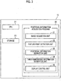
- the positional information acquisition device 15 is a computer and comprises a central processing unit (CPU) 21, a memory 22, and a storage 23 as the configuration of a standard computer.
- a positional information acquisition program is installed in the positional information acquisition device 15 according to this embodiment.
- the positional information acquisition program is stored in a storage device of a server computer connected to the network or a network storage such that it can be accessed from the outside, is downloaded to the positional information acquisition device 15 through the I/F unit 13 on demand, and is installed in the positional information acquisition device 15.
- the positional information acquisition program is recorded on a recording medium, such as a digital versatile disc (DVD) or a compact disc read only memory (CD-ROM), is distributed, and is installed in the positional information acquisition device 15 from the recording medium.
- DVD digital versatile disc
- CD-ROM compact disc read only memory
- the storage 23 is a storage device, such as a hard disk drive or a solid state drive (SSD), and stores various kinds of information including the positional information acquisition program.
- the radiographic image acquired by imaging is also stored in the storage 23.
- the positional information acquisition program defines, as processes performed by the CPU 21, an image acquisition process that acquires a radiographic image set including the first and second radiographic images G1 and G2 acquired by the radiography apparatus 1 at a predetermined time interval, a feature point detection process that detects at least one common feature point in the subject H from each of the first and second radiographic images G1 and G2 included in the radiographic image set, a positional information derivation process that derives three-dimensional positional information of at least one feature point in the subject H, using a positional relationship between the position of the feature point detected from the first and second radiographic images G1 and G2 on the detection surface 5A of the radiation detector 5 and the positions of the first and second radiation sources 6A and 6B, a three-dimensional information derivation process that derives three-dimensional information related to a target structure in the subject H, and a display control process that displays positional information on the user interface 16 as
- the CPU 21 performs these processes according to the positional information acquisition program such that the computer functions as the positional information acquisition device 15 comprising an image acquisition unit 31, a feature point detection unit 32, a positional information derivation unit 33, a three-dimensional information derivation unit 34, and a display control unit 35.
- the image acquisition unit 31 acquires a radiographic image set including the first and second radiographic images G1 and G2 of the subject H generated by the control of the imaging control unit 14 for the first and second radiation sources 6A and 6B and the radiation detector 5.
- a radiographic image set including the first and second radiographic images G1 and G2 of the subject H generated by the control of the imaging control unit 14 for the first and second radiation sources 6A and 6B and the radiation detector 5.
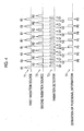
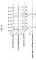
- Fig. 4 is a diagram illustrating the timing when the first and second radiation sources 6A and 6B emit the first and second radiations R1 and R2 and the timing when the radiation detector 5 detects the first and second radiations R1 and R2.
- Fig. 4 illustrates a timing T1 when the first radiation source 6A emits the first radiation R1, a timing T2 when the second radiation source 6B emits the second radiation R2, and a timing T3 when the radiation detector 5 detects the first and second radiations R1 and R2.
- T4 is a positional information derivation timing which will be described below.
- the radiation detector 5 detects the first radiation R1 transmitted through the subject H and generates the first radiographic image G1.
- the second radiation source 6B emits the second radiation R2 and the radiation detector 5 detects the second radiation R2 transmitted through the subject H and generates the second radiographic image G2.
- the first radiation source 6A emits the next first radiation R1 and the radiation detector 5 detects the next first radiation R1 transmitted through the subject H and generates the next first radiographic image G1. This is repeated to alternately and repeatedly acquire the first radiographic image G1 and the second radiographic image G2.
- the image acquisition unit 31 acquires the first and second radiographic images G1 and G2 that are temporally adjacent to each other as the radiographic image set.
- the time interval at which the radiation detector 5 generates the first and second radiographic images G1 and G2 is 25 to 60 fps, for example, 30 fps. In a case in which the time interval at which the first and second radiographic images G1 and G2 are generated is 30 fps, the timing when the first and second radiations R1 and R2 are emitted from the first and second radiation sources 6A and 6B, respectively, is 15 fps.
- FIG. 5 is a diagram illustrating a radioscopic image displayed on the user interface 16 in a case in which a catheter treatment is performed.
- a bifurcated stent 51 inserted into a guide wire 52 is inserted into the aorta 50 from the artery in one groin and one branch 51A of the stent 51 is expanded by the guide wire 52.
- an operation is performed which inserts another guide wire 53 into the aorta 50 from the artery in the other groin and passes the guide wire 53 through the other branch 51B of the stent 51 to expand the branch 51B of the stent 51.
- the first radiographic image G1 or the second radiographic image G2 of the abdominal aneurysm of the subject H is displayed as a radioscopic image of the moving image on the user interface 16.
- the user performs an operation of passing the guide wire 53 through the branch 51B of the stent 51 while viewing the radioscopic image displayed on the user interface 16.
- the diameter of the branch 51B of the stent 51 is small and the radioscopic image displayed on the user interface 16 is a two-dimensional image. Therefore, it is difficult to know a three-dimensional positional relationship between an end portion of the branch 51B of the stent 51 and a leading end 53A of the guide wire 53.
- the guide wire 53 seems to be inserted into the branch 51B of the stent 51.
- the guide wire 53 will not be inserted into the branch 51B.
- a radiographic image of the front of the subject H is captured, a screw insertion position is determined, a radioscopic image of the side of the subject H illustrated in Fig. 7 is displayed as a moving image, and a screw 55 is inserted into the lumbar spine 56 while a depth and an angle are checked.
- the radioscopic image is a two-dimensional image, it is difficult to know the insertion position and insertion angle of the screw 55 and erroneous insertion is likely to occur. This embodiment has been made in order to solve these problems.
- the feature point detection unit 32 detects at least one common feature point in the subject H from each of the first and second radiographic images G1 and G2 included in the radiographic image set. For example, in the case of the catheter treatment, the leading end 53A of the guide wire 53 included in each of the first and second radiographic images G1 and G2 is detected as the feature point. In the case of the lumbar spine fusion, a leading end 55A and a rear end 55B of the screw 55 included in each of the first and second radiographic images G1 and G2 are detected as the feature points. In this embodiment, the feature point detection unit 32 has a learned model which has been trained so as to detect the feature points in the first and second radiographic images G1 and G2.
- the feature point includes not only one pixel but also a region having a certain area formed by a plurality of pixels.
- the leading end 53A of the guide wire 53, the leading end 55A of the screw 55, and the rear end 55B of the screw 55 have a certain area and are included in the feature points in this embodiment.
- the learned model is a neural network that has been subjected to deep-learning so as to detect the feature points included in the first and second radiographic images G1 and G2.
- the learned model is generated by training a neural network using a large number of images, in which feature points have been known, as training data. Therefore, in a case in which the first and second radiographic images G1 and G2 are input, the feature point detection unit 32 detects a common feature point from the first and second radiographic images G1 and G2 and outputs the two-dimensional position coordinates of the detected feature point.
- the learned model may be, for example, a support vector machine (SVM), a convolutional neural network (CNN), and a recurrent neural network (RNN) in addition to the neural network subjected to deep learning.
- SVM support vector machine
- CNN convolutional neural network
- RNN recurrent neural network
- the feature point detection unit 32 detects the feature points using the learned model.
- the invention is not limited thereto.
- any method such as a method for detecting the feature points included in the first and second radiographic images G1 and G2 using template matching, may be used as a method for detecting the feature points.
- the positional information derivation unit 33 derives the three-dimensional positional information of the feature point in the subject H, using the positional relationship between the position of the feature point detected from the first and second radiographic images G1 and G2 on the detection surface 5A of the radiation detector 5 and the positions of the first and second radiation sources 6A and 6B.
- Fig. 8 is a diagram illustrating the derivation of the three-dimensional positional information of the feature point.
- the positional information derivation unit 33 acquires the information of a radiation source position S1 (sx1, sy1, sz1) of the first radiation source 6A, a radiation source position S2 (sx2, sy2, sz2) of the second radiation source 6B, a position D1 (dx1, dy1, dz1) of the feature point detected in the first radiographic image G1, and a position D2 (dx2, dy2, dz2) of the feature point detected in the second radiographic image G2 illustrated in Fig. 8 .
- the three-dimensional coordinates (sx1, sy1, sz1) of the radiation source position S1 and the three-dimensional coordinates (sx2, sy2, sz2) of the radiation source position S2 can be derived on the basis of the positional relationship between the origin and the first and second radiation sources 6A and 6B.
- a coordinate system having, as the origin, a point that bisects a line connecting the centers of the first and second emission portions 4A and 4B of the radiation emitting unit 4 can be set.
- the SID Since the SID is known, it is possible to derive the three-dimensional coordinates of the center position of the detection surface 5A of the radiation detector 5 with respect to the origin. In addition, it is possible to derive the three-dimensional coordinates of the positions D1 and D2 of the feature points from the two-dimensional position coordinates of the feature points in the first and second radiographic images G1 and G2 detected by the feature point detection unit 32, using the three-dimensional coordinates of the center position of the detection surface 5A of the radiation detector 5.
- the positional information derivation unit 33 sets a straight line L1 connecting the radiation source position S1 and the position D1 of the feature point and a straight line L2 connecting the radiation source position S2 and the position D2 of the feature point.
- Any point P1 on the straight line L1 and any point P2 on the straight line L2 are expressed by the following Expression (1) using the radiation source positions S1 and S2 and the positions D1 and D2 of the feature points.
- t and s are parameters.
- P 1 1 ⁇ t ⁇ S 1 + t ⁇ D 1
- P 2 1 ⁇ s ⁇ S 2 + s ⁇ D 2
- the positional information derivation unit 33 derives the three-dimensional coordinates of a point, at which the distance between the point P1 and the point P2 is the minimum, as three-dimensional positional information P0(x0, y0, z0) of the feature point detected in the first and second radiographic images G1 and G2, using the following Expression (2).
- P 0 min P 1 ⁇ P 2 2
- the positional information derivation unit 33 derives the positional information P0 using the first and second radiographic images G1 and G2 included in the acquired radiographic image set. Therefore, the timing when the positional information derivation unit 33 derives the positional information P0 is a timing T4 illustrated in Fig. 4 .
- the three-dimensional information derivation unit 34 captures the images of the subject H in two directions and derives three-dimensional information related to a target structure which is a target included in the subject H during a medical procedure. For example, in the case of a catheter treatment for the abdominal aneurysm, first, an operation is performed which expands the branch 51A after the stent 51 is inserted and inserts the guide wire 53 into the branch 51B. Therefore, the three-dimensional information derivation unit 34 derives the center position of the end portion of the branch 51B of the stent 51 as the three-dimensional information related to the target structure.
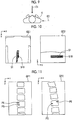
- Fig. 9 is a diagram illustrating the capture of the images of the subject H in two directions
- Fig. 10 is a diagram illustrating radiographic images acquired by the imaging in two directions.
- the C-arm 2 is moved in the state illustrated in Fig. 1 and the imaging control unit 14 irradiates the subject H with radiation in the direction of an arrow E1 illustrated in Fig. 9 to acquire a radiographic image GE1 illustrated in Fig. 10 in response to a command from the user.
- the radiation emitting unit 4 is moved to the right side of the subject H in Fig. 1 and the subject H is irradiated with radiation in the direction of an arrow E2 to acquire a radiographic image GE2 illustrated in Fig. 10 .
- the radiographic images GE1 and GE2 include the image of the stent 51.
- the coordinates of the center positions of the radiographic images GE1 and GE2 are known since they are matched with the coordinates of the center position of the detection surface 5A of the radiation detector 5. Therefore, the three-dimensional information derivation unit 34 derives the three-dimensional coordinates of the center position of the end portion of the branch 51B, into which the guide wire for the stent 51 is to be inserted, in the radiographic images GE1 and GE2 as the three-dimensional information of the target structure in the same coordinate system as that in a case in which the feature point is detected.
- the coordinate system is not limited to the same coordinate system as that in a case in which the feature point is detected.
- a coordinate system having the center position of the end portion of the branch 51B of the stent 51 as the origin may be set.
- the three-dimensional information derivation unit 34 may direct the radiography apparatus 1 to perform tomosynthesis imaging to generate a three-dimensional image of a target part of the subject H and may derive the three-dimensional information of a target structure from the three-dimensional image acquired by the tomosynthesis imaging.
- the three-dimensional information derivation unit 34 reconstructs the plurality of projection images using a back projection method, such as a simple back projection method or a filtered back projection method, to generate tomographic images in a plurality of tomographic planes of the subject H. Then, a three-dimensional image formed by the plurality of tomographic images is generated.
- a back projection method such as a simple back projection method or a filtered back projection method
- the three-dimensional information derivation unit 34 performs coordinate transform such that the coordinate system of the three-dimensional image is matched with the coordinate system of the feature point and derives the three-dimensional coordinates of the center position of the end portion of the branch 51B of the stent 51 as the three-dimensional information of the target structure.
- a coordinate system having the center position of the end portion of the branch 51B of the stent 51 as the origin may be set.
- the three-dimensional information derivation unit 34 may derive three-dimensional information from a three-dimensional image which has been acquired in advance by, for example a computed tomography (CT) apparatus or a magnetic resonance imaging (MRI) apparatus.
- CT computed tomography
- MRI magnetic resonance imaging
- the three-dimensional information derivation unit 34 may perform coordinate transform such that the coordinate system of the three-dimensional image which has been acquired in advance is matched with the coordinate system of the feature point and may derive the three-dimensional coordinates of the center position of the end portion of the branch 51B of the stent 51 as the three-dimensional information of the target structure.
- a coordinate system having the center position of the end portion of the branch 51B of the stent 51 as the origin may be set.
- the three-dimensional information derivation unit 34 derives, as the three-dimensional information of the target structure, the three-dimensional coordinates of an insertion position and an arrival position in the lumbar spine which has been specified in advance in the three-dimensional image of the subject H acquired by the CT apparatus or the MRI apparatus before a medical procedure.
- the three-dimensional information derivation unit 34 generates projection images GP1 and GP2 obtained by projecting the three-dimensional image in the direction of the arrow E1 and the direction of the arrow E2 illustrated in Fig. 9 , respectively.
- Fig. 11 is a diagram illustrating the projection images in two directions. As illustrated in Fig.
- the projection image GP1 is a front view of the lumbar spine of the subject H and the projection image GP2 is a side view of the lumbar spine of the subject H.
- the insertion position and the arrival position of the screw 55 are predetermined and set on the three-dimensional image by an examination before a medical procedure. Therefore, an insertion position PS and an arrival position PE are specified in the projection images GP1 and GP2.
- the three-dimensional information derivation unit 34 captures the images of the subject H in the two directions illustrated in Fig. 9 and acquires radiographic images GE11 and GE12 illustrated in Fig 12 . Then, the three-dimensional information derivation unit 34 matches the coordinate system of the radiographic images GE11 and GE12 with the coordinate system of the projection images GP1 and GP2 and specifies an insertion position PS1 and an arrival position PE1 in the radiographic images GE11 and GE12. In this case, it is preferable that the coordinate systems to be matched with each other have the insertion position PS in the projection images GP1 and GP2 as the origin. However, the invention is not limited thereto.
- the coordinate system of the radiographic images GE11 and GE12 may be matched with a coordinate system having any point on the projection images GP1 and GP2 as the origin or the coordinate system of the projection images GP1 and GP2 may be matched with the coordinate system of the radiographic images GE11 and GE12.
- Fig. 13 is a diagram illustrating a positional information screen in a case in which a catheter treatment is performed.
- a positional information screen 60 has a radioscopic image display region 61 and a display region 62 for the positional information P0.
- the first radiographic image G1 is sequentially displayed as a radioscopic image in the display region 61. Therefore, the radioscopic images are displayed as a moving image in the display region 61.
- the second radiographic image G2 may be sequentially displayed as the radioscopic image in the display region 61.
- the three-dimensional information derivation unit 34 derives the three-dimensional coordinates of the center position of the branch 51B of the stent 51 as the three-dimensional information of the target structure and the positional information derivation unit 33 derives the positional information P0 of the leading end 53A of the guide wire 53.
- the diameter of the branch 51B of the stent 51 is known. Therefore, the display control unit 35 generates a stent image GT0 schematically indicating the shape of the branch 51B of the stent 51 and displays the stent image GT0 in the positional information display region 62.
- the stent image GT0 is an image as the end portion of the branch 51B of the stent 51 is viewed from the direction of the central axis.
- the display control unit 35 displays a mark M0 indicating the position of the leading end 53A of the guide wire 53 in the display region 62.
- the display control unit 35 matches the positional relationship between the mark M0 and the stent image GT0 with the positional relationship between the leading end 53A of the guide wire 53 and the center position of the branch 51B of the stent 51 derived by the three-dimensional information derivation unit 34.
- the position of the leading end 53A of the guide wire 53 is acquired in three-dimensional coordinates. Therefore, the mark M0 indicates the position of the leading end 53A of the guide wire 53 in the image in which the branch 51B of the stent 51 is viewed from the direction of the central axis.
- the user performs an operation of inserting the guide wire 53 into the body of the subject H while viewing the positional information screen 60 such that the mark M0 is located in a circle indicating the end portion of the branch 51B in the stent image GT0.
- the positional relationship between the stent image GT0 and the mark M0 illustrated in Fig. 13 indicates that the leading end 53A of the guide wire 53 is separated from the end portion of the branch 51B of the stent 51.
- the user can adjust the position of the guide wire 53 inserted into the subject H such that the mark M0 is located in the stent image GT0. Therefore, it is possible to reduce errors in the insertion of the guide wire 53 into the stent 51 as illustrated in Fig. 6 .
- the display control unit 35 may notify that the guide wire 53 has reached the center position of the branch 51B of the stent 51 and has been inserted into the branch 51B through the user interface 16.
- the notification may be performed by text display or sound. Further, both display and sound may be used for the notification.
- the sound may be changed according to the distance between the leading end 53A of the guide wire 53 and the center position of the branch 51B.
- a beep sound may be intermittently output as the sound and the interval between the beep sounds may become shorter as the leading end 53A of the guide wire 53 becomes closer to the center position of the branch 51B.
- the sound may be changed in a case in which the leading end 53A of the guide wire 53 is inserted into the branch 51B.
- a warning indicating the fact may be issued through the user interface 16.
- Fig. 14 illustrates a positional information screen in a case in which lumbar spine fusion is performed.
- a positional information screen 70 has a radioscopic image display region 71 and a positional information display region 72.
- the first radiographic image G1 obtained by capturing the image of the lumbar spine from the side is sequentially displayed in the display region 71. Therefore, the radioscopic images are displayed as a moving image in the display region 71.
- the first radiographic image G1 includes an image of the screw 55.
- the second radiographic image G2 may be sequentially displayed as a radioscopic image in the display region 71.
- the three-dimensional information derivation unit 34 derives the three-dimensional coordinates of the insertion position PS and the arrival position PE of the screw 55 in the lumbar spine as the three-dimensional information of the target structure.
- the positional information derivation unit 33 derives the positional information P0 of the leading end 55A and the rear end 55B of the screw 55. Therefore, the display control unit 35 generates a tomographic image GD0 of the lumbar spine into which the screw 55 is inserted, using the three-dimensional image of the subject H which has been acquired in advance, and displays the generated tomographic image GD0 in the positional information display region 72.
- the tomographic image GD0 of the lumbar spine displayed in the display region 72 indicates an axial cross section.
- the display control unit 35 displays a mark M1 obtained by projecting the screw 55 derived by the positional information derivation unit 33 onto the tomographic plane of the tomographic image GD0 in the positional information display region 72.
- the display control unit 35 matches the positional relationship between the leading end and the rear end of the mark M1 and the insertion position PS and the arrival position PE on the tomographic image GD0 with the positional relationship between the leading end 55A and the rear end 55B of the screw 55 and the insertion position PS and the arrival position PE derived by the three-dimensional information derivation unit 34.
- the display control unit 35 displays the remaining distance from the leading end 55A of the screw 55 to the insertion position PS derived by the positional information derivation unit 33 in an information display region 74 until the screw 55 reaches the insertion position PS.
- the coordinate system having the insertion position PS as the origin is also set for the radiographic images G1 and G2, it is possible to derive the distance from the current position of the leading end 55A of the screw 55 from the origin as the remaining distance from the leading end 55A of the screw 55 to the insertion position PS.
- the display control unit 35 derives an angle (referred to as a first angle) of the axis of the screw 55 with respect to the axial cross section from the positions of the leading end 55A and the rear end 55B of the screw 55 derived by the positional information derivation unit 33.
- an angle (referred to as a second angle) at which the screw 55 is to be inserted is derived from the insertion position PS and the arrival position PE derived by the three-dimensional information derivation unit 34. Then, the difference of the first angle from the second angle is derived and the derived angle is displayed in the information display region 74. In Fig. 14 , a remaining distance of 10 mm and an angle of 0 degrees are displayed.
- the angle of 0 degrees indicates that the angle at which the screw 55 is inserted is matched with the angle formed by the insertion position PS and the arrival position PE. After the screw 55 is inserted into the lumbar spine from the insertion position PS, the remaining distance from the leading end 55A of the screw 55 to the arrival position PE may be displayed in the information display region 74.
- the display control unit 35 may issue a warning in a case in which the leading end 55A of the screw 55 is at a position that is separated from the insertion position PS by a predetermined threshold value or more. Further, in a case in which the angle of the screw 55 is greater than a predetermined threshold value (for example, 10 degrees), the display control unit 35 may issue a warning.
- a predetermined threshold value for example, 10 degrees
- the user can insert the screw 55 into the body of the subject H such that the screw 55 is inserted into the lumbar spine from the insertion position PS while viewing the display of the tomographic image GD0, the mark M1, and the information display region 74.
- the user can insert the screw 55 into the lumbar spine of the subject H such that the inserted screw 55 correctly reaches the arrival position PE.
- the display control unit 35 may notify that the leading end 55A of the screw 55 has reached the insertion position PS and the leading end 55A of the screw 55 has reached the arrival position PE through the user interface 16.
- the notification may be performed in a case in which the angle of the screw 55 is matched with the angle at which the screw 55 is to be inserted.
- the notification may be performed by text display or sound. Further, both display and sound may be used.
- the sound may be changed according to the distance between the leading end 55A of the screw 55 and the insertion position PS and the arrival position PE.
- a beep sound may be intermittently output as the sound and the interval between the beep sounds may become shorter as the leading end 55A of the screw 55 becomes closer to the insertion position PS and the arrival position PE.
- the sound may be changed in a case in which the leading end 55A of the screw 55 reaches the insertion position PS and the arrival position PE.
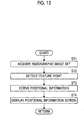
- FIG. 15 is a flowchart illustrating the process performed in this embodiment. It is assumed that the three-dimensional information of a target structure has been derived in advance by the three-dimensional information derivation unit 34 and then stored in the storage 23.
- the user inputs an imaging start command through the user interface 16 to start the process and the image acquisition unit 31 acquires a set of the first radiographic image G1 and the second radiographic image G2 (the acquisition of a radiographic image set; Step ST1).
- the feature point detection unit 32 detects at least one common feature point from the first and second radiographic images G1 and G2 (Step ST2).
- the positional information derivation unit 33 derives the three-dimensional positional information of at least one feature point in the subject H, using the positional relationship between the position of at least one feature point detected from each of the first and second radiographic images G1 and G2 on the detection surface 5A of the radiation detector 5 and the positions of the first and second radiation sources 6A and 6B (Step ST3).
- the display control unit 35 displays a positional information screen on the user interface 16 (Step ST4).
- the process returns to Step ST1.
- the process from Step ST1 to Step ST4 is repeatedly performed until a process end command is issued.
- At least one common feature point in the subject H is detected from each of the first and second radiographic images G1 and G2 and the three-dimensional positional information of at least one feature point in the subject H is derived using the positional relationship between the position of at least one feature point detected from each of the first and second radiographic images G1 and G2 on the detection surface 5A of the radiation detector 5 and the positions of the first and second radiation sources 6A and 6B. Therefore, it is possible to acquire the three-dimensional positional information of a feature point, using a smaller amount of calculation as that in a case in which a three-dimensional image is generated from a plurality of radiographic images. As a result, according to this embodiment, it is possible to understand the three-dimensional position of a feature point, such as a surgical instrument, in the subject H in real time.
- a feature point such as a surgical instrument
- the first radiographic image G1 and the second radiographic image G2 are alternately acquired.
- the invention is not limited thereto.
- one second radiographic image G2 may be acquired for every several frames of the first radiographic images G1.
- the second radiographic image G2 is acquired once while four frames of the first radiographic images G1 are acquired. In this case, the derivation of the positional information is performed once while four frames of the first radiographic images G1 are acquired.
- the three-dimensional information derivation unit 34 derives the center position of the branch 51B of the stent 51 as the three-dimensional information of the target structure.
- the feature point detection unit 32 may detect the center position of the branch 51B of the stent 51 as a feature point different from the leading end 53A of the guide wire 53 from the first and second radiographic images G1 and G2 and the positional information derivation unit 33 may derive the positional information of the center position of the branch 51B.
- radiation is not particularly limited and rays other than X-rays, such as ⁇ -rays or ⁇ -rays, may be applied.
- the positional information acquisition device and the radiography apparatus are applied.
- the invention is not limited thereto.
- the present disclosure may be applied to any medical procedure using a radioscopic image.
- the first and second radiation sources 6A and 6B are arranged in the y-axis direction illustrated in Fig. 1 in the radiation emitting unit 4.
- the first and second radiation sources 6A and 6B may be arranged in the x-axis direction.
- the radiation emitting unit 4 includes the two radiation sources 6A and 6B.
- the radiation emitting unit 4 may include three or more radiation sources.
- the positional information may be derived using a plurality of radiographic images acquired by irradiating the subject H with radiation emitted from three or more radiation sources.
- the positional information may be derived using a combination of two radiographic images generated by radiation emitted from two radiation sources among three or more radiation sources.
- the following various processors can be used as the hardware structure of processing units performing various processes, such as the image acquisition unit 31, the feature point detection unit 32, the positional information derivation unit 33, the three-dimensional information derivation unit 34, and the display control unit 35.
- the various processors include a CPU which is a general-purpose processor executing software (program) to function as various processing units, a programmable logic device (PLD), such as a field programmable gate array (FPGA), which is a processor whose circuit configuration can be changed after manufacture, and a dedicated electric circuit, such as an application specific integrated circuit (ASIC), which is a processor having a dedicated circuit configuration designed to perform a specific process.
- PLD programmable logic device
- FPGA field programmable gate array
- ASIC application specific integrated circuit
- One processing unit may be configured by one of the various processors or a combination of two or more processors of the same type or different types (for example, a combination of a plurality of FPGAs or a combination of a CPU and an FPGA).
- a plurality of processing units may be configured by one processor.
- a first example of the configuration in which a plurality of processing units are configured by one processor is an aspect in which one processor is configured by a combination of one or more CPUs and software and functions as a plurality of processing units.
- a representative example of this aspect is a client computer or a server computer.
- a second example of the configuration is an aspect in which a processor that implements the functions of the entire system including a plurality of processing units using one integrated circuit (IC) chip is used.
- IC integrated circuit
- a representative example of this aspect is a system-on-chip (SoC).
- SoC system-on-chip
- various processing units are configured by using one or more of the various processors as a hardware structure.
- an electric circuit obtained by combining circuit elements, such as semiconductor elements, can be used as the hardware structure of the various processors.
Landscapes
- Health & Medical Sciences (AREA)
- Life Sciences & Earth Sciences (AREA)
- Engineering & Computer Science (AREA)
- Medical Informatics (AREA)
- Physics & Mathematics (AREA)
- Nuclear Medicine, Radiotherapy & Molecular Imaging (AREA)
- General Health & Medical Sciences (AREA)
- Radiology & Medical Imaging (AREA)
- Biomedical Technology (AREA)
- Veterinary Medicine (AREA)
- Pathology (AREA)
- High Energy & Nuclear Physics (AREA)
- Biophysics (AREA)
- Heart & Thoracic Surgery (AREA)
- Molecular Biology (AREA)
- Surgery (AREA)
- Animal Behavior & Ethology (AREA)
- Optics & Photonics (AREA)
- Public Health (AREA)
- Computer Vision & Pattern Recognition (AREA)
- Theoretical Computer Science (AREA)
- General Physics & Mathematics (AREA)
- Pulmonology (AREA)
- Quality & Reliability (AREA)
- Human Computer Interaction (AREA)
- Apparatus For Radiation Diagnosis (AREA)
Abstract
Description
- The present disclosure relates to a positional information acquisition device, a positional information acquisition method, a positional information acquisition program, and a radiography apparatus that acquire three-dimensional positional information of a feature point in a subject.
- In surgical operations and catheter treatments, it is necessary to understand the positional relationship between surgical instruments and human body structure such as bones and blood vessels. However, in the related art, in many cases, the understanding of the positional relationship between a surgical instrument and a human body structure depends on the experience and intuition of a doctor and there are problems of an error in the insertion of the surgical instrument and excessive surgery time. For this reason, a process is performed which captures an image of a subject using a radioscopy apparatus during surgery and understands the positional relationship between a surgical instrument and a human body structure using a radioscopic image displayed on a display by imaging. However, while a three-dimensional positional relationship is established between the surgical instrument and the human body structure, the radioscopic image is a two-dimensional image. It is difficult for the user to understand the three-dimensional positional relationship between the surgical instrument and the human body structure even in a case in which the user views the two-dimensional radioscopic image.
- For this reason, a process is performed which understands a three-dimensional positional relationship between a surgical instrument and a human body structure, using radioscopic images in a plurality of directions acquired by capturing the images of a patient as a subject while changing an angle during a medical procedure or by using a plurality of imaging apparatuses at the same time. In addition, a method has been proposed in which a sensor is attached to a surgical instrument to understand the three-dimensional position of the surgical instrument.
- However, in a case in which an image of a subject is captured while the angle is changed, it is necessary to move the imaging apparatus during a medical procedure. In addition, in a case in which a plurality of imaging apparatuses are used at the same time, it is not necessary to move the imaging apparatuses, but a work space for the doctor during surgery is reduced, which may hinder the procedure. Further, in the method using a sensor, it is necessary to prepare a sensor.
- For this reason, a method has been proposed which acquires a plurality of radiographic images obtained by irradiating a subject with radiation emitted from a plurality of radiation sources arranged at intervals to capture the images of the subject at a plurality of positions and generates a three-dimensional radiographic image, in which the subject can be viewed stereoscopically, from the plurality of radiographic images (for example, see
JP2014-226174A JP2014-226174A - In surgical operations and catheter treatments, it is necessary to understand the positional relationship between a surgical instrument and a human body structure in real time. However, in the method described in
JP2014-226174A JP2014-226174A - The present disclosure has been made in view of the above-mentioned problems and an object of the present disclosure is to provide a technique that enables a user to understand a three-dimensional position of a feature point, such as a surgical instrument, in a subject in real time.
- According to the present disclosure, there is provided a positional information acquisition device comprising: an image acquisition unit that acquires a radiographic image set including a plurality of radiographic images, which have been generated by alternately irradiating a subject with radiation emitted from a plurality of radiation sources provided at different positions and alternately detecting the radiation transmitted through the subject using one detection unit, at a predetermined time interval; a feature point detection unit that detects at least one common feature point in the subject from each of the plurality of radiographic images included in the radiographic image set; and a positional information derivation unit that derives three-dimensional positional information of the at least one feature point in the subject using a positional relationship between a position of the at least one feature point detected from each of the plurality of radiographic images on a detection surface of the detection unit and positions of the plurality of radiation sources.
- The "predetermined time interval" means, for example, a time interval corresponding to the frame rate of a moving image. The predetermined time interval may be, for example, 25 to 60 fps. As a result, in the present disclosure, a combination of radiographic images, such as a moving image, is acquired. In addition, all of the plurality of radiographic images may be acquired at the same time interval or the plurality of radiographic images may be acquired at different time intervals.
- The positional information acquisition device according to the present disclosure may further comprise a display control unit that displays the positional information on a display unit.
- In the positional information acquisition device according to the present disclosure, the feature point detection unit may detect a point on a surgical instrument inserted into the subject as the feature point.
- According to the present disclosure, there is provided a radiography apparatus comprising: a plurality of radiation sources that are provided at a predetermined interval; a detection unit that is provided so as to face the plurality of radiation sources, detects radiation which has been emitted from each of the plurality of radiation sources and transmitted through a subject, and generates a radiographic image of the subject; an imaging control unit that generates a radiographic image set including a plurality of radiographic images at a predetermined time interval by controlling a timing when each of the plurality of radiation sources emits the radiation and a timing when the detection unit detects the radiation transmitted through the subject such that the plurality of radiation sources alternately irradiate the subject with the radiation and the detection unit alternately detects the radiation transmitted through the subject; and the positional information acquisition device according to the present disclosure.
- In the radiography apparatus according to the present disclosure, the number of radiation sources may be 2.
- In the radiography apparatus according to the present disclosure, the imaging control unit may direct one of the two radiation sources to sequentially emit radiation at a first time interval, direct the other radiation source to sequentially emit radiation at a second time interval equal to or longer than the first time interval, and control the detection unit so as to detect the radiation at all timings when the two radiation sources emit the radiation. The image acquisition unit may acquire, as the radiographic image set, two radiographic images generated by detecting two temporally adjacent radiations which have been emitted from the two radiation sources using the detection unit.
- The term "being equal to or longer than the first time interval" means being equal to the first time interval and being longer than the first time interval.
- According to the present disclosure, there is provided a positional information acquisition method comprising: acquiring a radiographic image set including a plurality of radiographic images, which have been generated by alternately irradiating a subject with radiation emitted from a plurality of radiation sources provided at different positions and alternately detecting the radiation transmitted through the subject using one detection unit, at a predetermined time interval; detecting at least one common feature point in the subject from each of the plurality of radiographic images included in the radiographic image set; and deriving three-dimensional positional information of the at least one feature point in the subject using a positional relationship between a position of the at least one feature point detected from each of the plurality of radiographic images on a detection surface of the detection unit and positions of the plurality of radiation sources.
- In addition, a program that causes a computer to perform the positional information acquisition method according to the present disclosure may be provided.
- According to the present disclosure, there is provided another positional information acquisition device comprising a memory that stores commands to be executed by a computer and a processor that is configured to execute the stored commands. The processor performs a process of acquiring a radiographic image set including a plurality of radiographic images, which have been generated by alternately irradiating a subject with radiation emitted from a plurality of radiation sources provided at different positions and alternately detecting the radiation transmitted through the subject using one detection unit, at a predetermined time interval, a process of detecting at least one common feature point in the subject from each of the plurality of radiographic images included in the radiographic image set, and a process of deriving three-dimensional positional information of the at least one feature point in the subject using a positional relationship between a position of the at least one feature point detected from each of the plurality of radiographic images on a detection surface of the detection unit and positions of the plurality of radiation sources.
- According to the present disclosure, it is possible to understand the position of feature points, such as a surgical instrument and a human body structure, in the subject in real time.
-
-
Fig. 1 is a diagram schematically illustrating the configuration of a radiography apparatus to which a positional information acquisition device according to an embodiment of the present disclosure is applied. -
Fig. 2 is a diagram schematically illustrating the configuration of a radiation emitting unit. -
Fig. 3 is a diagram schematically illustrating the configuration of the positional information acquisition device implemented by installing a positional information acquisition program in a computer in this embodiment. -
Fig. 4 is a diagram illustrating the timing when first and second radiation sources emit radiation and the timing when a radiation detector detects radiation. -
Fig. 5 is a diagram illustrating a radioscopic image displayed in a case in which a catheter treatment is performed. -
Fig. 6 is a diagram illustrating a state in which there is a difference between the positions of a stent and a guide wire. -
Fig. 7 is a diagram illustrating lumbar spine fusion. -
Fig. 8 is a diagram illustrating the derivation of three-dimensional positional information of a feature point. -
Fig. 9 is a diagram illustrating imaging in two directions. -
Fig. 10 is a diagram illustrating radiographic images acquired by imaging in two directions. -
Fig. 11 is a diagram illustrating projection images in two directions generated from a three-dimensional image. -
Fig. 12 is a diagram illustrating radiographic images acquired by imaging in two directions. -
Fig. 13 is a diagram illustrating a positional information screen in the case of a catheter treatment. -
Fig. 14 is a diagram illustrating a positional information screen in the case of lumbar spine fusion. -
Fig. 15 is a flowchart illustrating a process performed in this embodiment. -
Fig. 16 is a diagram illustrating the timing when the first and second radiation sources emit radiation and the timing when the radiation detector detects radiation. - Hereinafter, an embodiment of the present disclosure will be described with reference to the drawings.
Fig. 1 is a diagram schematically illustrating the configuration of a radiography apparatus to which a positional information acquisition device according to the embodiment of the present disclosure is applied. The radiography apparatus according to this embodiment acquires and displays a radioscopic image of a subject H as a moving image in a case in which, for example, a surgical operation and a catheter treatment are performed on the subject H. - In this embodiment, it is assumed that the x-axis is set as the left-right direction of
Fig. 1 , the y-axis is set as the depth direction ofFig. 1 , and the z-axis is set as a direction perpendicular to the plane on which the radiography apparatus 1 illustrated inFig. 1 is placed. - As illustrated in
Fig. 1 , the radiography apparatus 1 according to this embodiment comprises a C-arm 2. Animaging unit 3 is attached to one end portion of the C-arm 2 and aradiation emitting unit 4 is attached to the other end portion so as to face theimaging unit 3. - A
radiation detector 5, such as a flat panel detector, is provided in theimaging unit 3. Theradiation detector 5 corresponds to a detection unit according to the present disclosure. In addition, for example, a circuit substrate provided with a charge amplifier that converts a charge signal read from theradiation detector 5 into a voltage signal, a correlated double sampling circuit that samples the voltage signal output from the charge amplifier, an analog-to-digital (AD) conversion unit that converts the voltage signal into a digital signal, and the like is provided in theimaging unit 3. In this embodiment, theradiation detector 5 is used. However, the detector is not limited to theradiation detector 5 as long as it can detect radiation and convert the radiation into an image. For example, a detection device, such as an image intensifier, may be used. - The
radiation detector 5 can repeatedly perform the recording and reading of a radiographic image and may be a so-called direct-type radiation detector that directly converts radiation, such as X-rays, into charge or a so-called indirect-type radiation detector that converts radiation into visible light and then converts the visible light into a charge signal. In addition, it is preferable that a so-called TFT reading method which turns on and off a thin film transistor (TFT) switch to read a radiographic image signal or a so-called optical reading method which emits reading light to read a radiographic image signal is used as a radiographic image signal reading method. However, the invention is not limited thereto and other reading methods may be used. -
Fig. 2 is a diagram schematically illustrating the configuration of theradiation emitting unit 4. As illustrated inFig. 2 , afirst radiation source 6A and asecond radiation source 6B are provided in theradiation emitting unit 4. The first andsecond radiation sources Fig. 1 . First and second radiations R1 and R2 emitted from the first andsecond radiation sources imaging unit 3 through first andsecond emission portions - The first and
second radiation sources imaging control unit 14 which will be described below controls the timing when the first andsecond radiation sources radiation detector 5 detects the first and second radiations R1 and R2. In addition, for example, theimaging control unit 14 controls the radiation generation conditions of the first andsecond radiation sources - In the radiography apparatus 1 according to this embodiment, a so-called source image distance (SID) which is a distance between a
detection surface 5A of theradiation detector 5 and the first andsecond radiation sources radiation emitting unit 4 is a fixed value. - The C-
arm 2 according to this embodiment is held by a C-arm holding portion 7 such that the C-arm 2 can be moved in the direction of an arrow A illustrated inFig. 1 and the angle of theimaging unit 3 and theradiation emitting unit 4 with respect to the z direction (vertical direction) illustrated inFig. 1 can be integrally changed. Further, the C-arm holding portion 7 has a shaft portion 8 and the shaft portion 8 connects the C-arm 2 to a bearing 9 so as to be rotatable. Therefore, the C-arm 2 is rotatable on the shaft portion 8 as a rotation axis in the direction of an arrow B illustrated inFig. 1 . - In addition, as illustrated in
Fig. 1 , the radiography apparatus 1 according to this embodiment comprises amain body unit 10. Themain body unit 10 has a plurality ofwheels 11 attached to the bottom. Therefore, the radiography apparatus 1 according to this embodiment can be moved. Asupport shaft 12 that expands and contracts in the z-axis direction ofFig. 1 is provided in an upper part of a housing of themain body unit 10 inFig. 1 . The bearing 9 is held above thesupport shaft 12 so as to be movable in the direction of an arrow C. - Since the radiography apparatus 1 according to this embodiment has the above-mentioned configuration, the subject H who lies in a supine position on the imaging table 40 is irradiated with radiation from the lower side of the subject H and the
radiation detector 5 of theimaging unit 3 detects the radiation transmitted through the subject H to acquire a radiographic image of the subject H. Here, the C-arm 2 is movable in the direction of the arrow A, the direction of the arrow B, and the direction of the arrow C and the radiography apparatus 1 is movable by thewheels 11. Therefore, the radiography apparatus 1 according to this embodiment can capture an image of a desired part of the subject H who lies in a supine position on the imaging table 40 in a desired direction. - The
main body unit 10 is provided with an interface (I/F)unit 13, theimaging control unit 14, and a positionalinformation acquisition device 15 according to this embodiment. - The I/
F unit 13 has a function of performing wireless or wired communication with an external apparatus and a console that controls the overall operation related to the capture of a radiographic image by the radiography apparatus 1 (which are not illustrated). The radiography apparatus 1 according to this embodiment captures an image of the subject H on the basis of an imaging command received from the console through the I/F unit 13. - The
imaging control unit 14 directs the first andsecond radiation sources radiation emitting unit 4 to emit the first and second radiations R1 and R2 on the basis of the imaging conditions associated with an imaging command from the console, respectively. In addition, theimaging control unit 14 directs theradiation detector 5 of theimaging unit 3 to detect the first and second radiations R1 and R2 transmitted through the subject H according to the timing when the first and second radiations R1 and R2 are emitted from the first andsecond radiation sources main body unit 10. The timing when the first and second radiations R1 and R2 are emitted from the first andsecond radiation sources radiation detector 5 detects the first and second radiations R1 and R2 will be described below. - In addition, a
user interface 16 is provided above themain body unit 10. Theuser interface 16 has a function by which a user, such as a technician or a doctor who takes a radiographic image using the radiography apparatus 1, inputs a command related to the capture of a radiographic image, a function which displays a radiographic image acquired by imaging as a radioscopic image, and a function which provides information related to the capture of a radiographic image to the user. A touch panel display is given an example of theuser interface 16. - Next, the positional information acquisition device according to this embodiment will be described.
Fig. 3 is a diagram schematically illustrating the configuration of the positional information acquisition device according to this embodiment. As illustrated inFig. 3 , the positionalinformation acquisition device 15 is a computer and comprises a central processing unit (CPU) 21, amemory 22, and astorage 23 as the configuration of a standard computer. - A positional information acquisition program according to this embodiment is installed in the positional
information acquisition device 15 according to this embodiment. The positional information acquisition program is stored in a storage device of a server computer connected to the network or a network storage such that it can be accessed from the outside, is downloaded to the positionalinformation acquisition device 15 through the I/F unit 13 on demand, and is installed in the positionalinformation acquisition device 15. Alternatively, the positional information acquisition program is recorded on a recording medium, such as a digital versatile disc (DVD) or a compact disc read only memory (CD-ROM), is distributed, and is installed in the positionalinformation acquisition device 15 from the recording medium. - The
storage 23 is a storage device, such as a hard disk drive or a solid state drive (SSD), and stores various kinds of information including the positional information acquisition program. The radiographic image acquired by imaging is also stored in thestorage 23. - For example, the programs stored in the
storage 23 are temporarily stored in thememory 22 in order to cause theCPU 21 to perform various processes. The positional information acquisition program defines, as processes performed by theCPU 21, an image acquisition process that acquires a radiographic image set including the first and second radiographic images G1 and G2 acquired by the radiography apparatus 1 at a predetermined time interval, a feature point detection process that detects at least one common feature point in the subject H from each of the first and second radiographic images G1 and G2 included in the radiographic image set, a positional information derivation process that derives three-dimensional positional information of at least one feature point in the subject H, using a positional relationship between the position of the feature point detected from the first and second radiographic images G1 and G2 on thedetection surface 5A of theradiation detector 5 and the positions of the first andsecond radiation sources user interface 16 as described below. - Then, the
CPU 21 performs these processes according to the positional information acquisition program such that the computer functions as the positionalinformation acquisition device 15 comprising animage acquisition unit 31, a featurepoint detection unit 32, a positionalinformation derivation unit 33, a three-dimensionalinformation derivation unit 34, and adisplay control unit 35. - The
image acquisition unit 31 acquires a radiographic image set including the first and second radiographic images G1 and G2 of the subject H generated by the control of theimaging control unit 14 for the first andsecond radiation sources radiation detector 5. Next, the timing when the first andsecond radiation sources radiation detector 5 detects the first and second radiations R1 and R2 will be described.Fig. 4 is a diagram illustrating the timing when the first andsecond radiation sources radiation detector 5 detects the first and second radiations R1 and R2. -
Fig. 4 illustrates a timing T1 when thefirst radiation source 6A emits the first radiation R1, a timing T2 when thesecond radiation source 6B emits the second radiation R2, and a timing T3 when theradiation detector 5 detects the first and second radiations R1 and R2. In addition, T4 is a positional information derivation timing which will be described below. - As illustrated in
Fig. 4 , in a case in which the first radiation R1 is emitted from thefirst radiation source 6A, theradiation detector 5 detects the first radiation R1 transmitted through the subject H and generates the first radiographic image G1. In a case in which theradiation detector 5 generates the first radiographic image G1, thesecond radiation source 6B emits the second radiation R2 and theradiation detector 5 detects the second radiation R2 transmitted through the subject H and generates the second radiographic image G2. In a case in which theradiation detector 5 generates the second radiographic image G2, thefirst radiation source 6A emits the next first radiation R1 and theradiation detector 5 detects the next first radiation R1 transmitted through the subject H and generates the next first radiographic image G1. This is repeated to alternately and repeatedly acquire the first radiographic image G1 and the second radiographic image G2. Theimage acquisition unit 31 acquires the first and second radiographic images G1 and G2 that are temporally adjacent to each other as the radiographic image set. - The time interval at which the
radiation detector 5 generates the first and second radiographic images G1 and G2 is 25 to 60 fps, for example, 30 fps. In a case in which the time interval at which the first and second radiographic images G1 and G2 are generated is 30 fps, the timing when the first and second radiations R1 and R2 are emitted from the first andsecond radiation sources - Here, a medical procedure in a case in which a catheter treatment is performed for the abdominal aneurysm of the subject H using the radiography apparatus 1 according to this embodiment will be described.
Fig. 5 is a diagram illustrating a radioscopic image displayed on theuser interface 16 in a case in which a catheter treatment is performed. As illustrated inFig. 5 , in a case in which a catheter treatment for the abdominal aneurysm is performed, abifurcated stent 51 inserted into aguide wire 52 is inserted into theaorta 50 from the artery in one groin and onebranch 51A of thestent 51 is expanded by theguide wire 52. Then, an operation is performed which inserts anotherguide wire 53 into theaorta 50 from the artery in the other groin and passes theguide wire 53 through theother branch 51B of thestent 51 to expand thebranch 51B of thestent 51. In this case, in this embodiment, the first radiographic image G1 or the second radiographic image G2 of the abdominal aneurysm of the subject H is displayed as a radioscopic image of the moving image on theuser interface 16. The user performs an operation of passing theguide wire 53 through thebranch 51B of thestent 51 while viewing the radioscopic image displayed on theuser interface 16. - Here, the diameter of the
branch 51B of thestent 51 is small and the radioscopic image displayed on theuser interface 16 is a two-dimensional image. Therefore, it is difficult to know a three-dimensional positional relationship between an end portion of thebranch 51B of thestent 51 and aleading end 53A of theguide wire 53. For example, in the radioscopic image illustrated inFig. 5 , theguide wire 53 seems to be inserted into thebranch 51B of thestent 51. However, in practice, as illustrated inFig. 6 , there is a possibility that theguide wire 53 will not be inserted into thebranch 51B. - Further, in a case in which lumbar spine fusion is performed, a radiographic image of the front of the subject H is captured, a screw insertion position is determined, a radioscopic image of the side of the subject H illustrated in
Fig. 7 is displayed as a moving image, and ascrew 55 is inserted into thelumbar spine 56 while a depth and an angle are checked. However, since the radioscopic image is a two-dimensional image, it is difficult to know the insertion position and insertion angle of thescrew 55 and erroneous insertion is likely to occur. This embodiment has been made in order to solve these problems. - The feature
point detection unit 32 detects at least one common feature point in the subject H from each of the first and second radiographic images G1 and G2 included in the radiographic image set. For example, in the case of the catheter treatment, theleading end 53A of theguide wire 53 included in each of the first and second radiographic images G1 and G2 is detected as the feature point. In the case of the lumbar spine fusion, aleading end 55A and arear end 55B of thescrew 55 included in each of the first and second radiographic images G1 and G2 are detected as the feature points. In this embodiment, the featurepoint detection unit 32 has a learned model which has been trained so as to detect the feature points in the first and second radiographic images G1 and G2. - The feature point includes not only one pixel but also a region having a certain area formed by a plurality of pixels. For example, the
leading end 53A of theguide wire 53, theleading end 55A of thescrew 55, and therear end 55B of thescrew 55 have a certain area and are included in the feature points in this embodiment. - The learned model is a neural network that has been subjected to deep-learning so as to detect the feature points included in the first and second radiographic images G1 and G2. The learned model is generated by training a neural network using a large number of images, in which feature points have been known, as training data. Therefore, in a case in which the first and second radiographic images G1 and G2 are input, the feature
point detection unit 32 detects a common feature point from the first and second radiographic images G1 and G2 and outputs the two-dimensional position coordinates of the detected feature point. - The learned model may be, for example, a support vector machine (SVM), a convolutional neural network (CNN), and a recurrent neural network (RNN) in addition to the neural network subjected to deep learning.
- In this embodiment, the feature
point detection unit 32 detects the feature points using the learned model. However, the invention is not limited thereto. For example, any method, such as a method for detecting the feature points included in the first and second radiographic images G1 and G2 using template matching, may be used as a method for detecting the feature points. - The positional
information derivation unit 33 derives the three-dimensional positional information of the feature point in the subject H, using the positional relationship between the position of the feature point detected from the first and second radiographic images G1 and G2 on thedetection surface 5A of theradiation detector 5 and the positions of the first andsecond radiation sources Fig. 8 is a diagram illustrating the derivation of the three-dimensional positional information of the feature point. The positionalinformation derivation unit 33 acquires the information of a radiation source position S1 (sx1, sy1, sz1) of thefirst radiation source 6A, a radiation source position S2 (sx2, sy2, sz2) of thesecond radiation source 6B, a position D1 (dx1, dy1, dz1) of the feature point detected in the first radiographic image G1, and a position D2 (dx2, dy2, dz2) of the feature point detected in the second radiographic image G2 illustrated inFig. 8 . - In a case in which a coordinate system having, as the origin, any position on the C-
arm 2 of the radiography apparatus 1 is set, the three-dimensional coordinates (sx1, sy1, sz1) of the radiation source position S1 and the three-dimensional coordinates (sx2, sy2, sz2) of the radiation source position S2 can be derived on the basis of the positional relationship between the origin and the first andsecond radiation sources second emission portions radiation emitting unit 4 can be set. - Since the SID is known, it is possible to derive the three-dimensional coordinates of the center position of the
detection surface 5A of theradiation detector 5 with respect to the origin. In addition, it is possible to derive the three-dimensional coordinates of the positions D1 and D2 of the feature points from the two-dimensional position coordinates of the feature points in the first and second radiographic images G1 and G2 detected by the featurepoint detection unit 32, using the three-dimensional coordinates of the center position of thedetection surface 5A of theradiation detector 5. - The positional
information derivation unit 33 sets a straight line L1 connecting the radiation source position S1 and the position D1 of the feature point and a straight line L2 connecting the radiation source position S2 and the position D2 of the feature point. Any point P1 on the straight line L1 and any point P2 on the straight line L2 are expressed by the following Expression (1) using the radiation source positions S1 and S2 and the positions D1 and D2 of the feature points. In Expression (1), t and s are parameters.

- Ideally, the feature point in the subject H detected in the first and second radiographic images G1 and G2 is located at an intersection point between the point P1 on the straight line L1 and the point P2 on the straight line L2 in a three-dimensional space. Therefore, in this embodiment, the positional
information derivation unit 33 derives the three-dimensional coordinates of a point, at which the distance between the point P1 and the point P2 is the minimum, as three-dimensional positional information P0(x0, y0, z0) of the feature point detected in the first and second radiographic images G1 and G2, using the following Expression (2).
- In a case in which the
image acquisition unit 31 acquires a radiographic image set including the first and second radiographic images G1 and G2 at successive timings, the positionalinformation derivation unit 33 derives the positional information P0 using the first and second radiographic images G1 and G2 included in the acquired radiographic image set. Therefore, the timing when the positionalinformation derivation unit 33 derives the positional information P0 is a timing T4 illustrated inFig. 4 . - The three-dimensional
information derivation unit 34 captures the images of the subject H in two directions and derives three-dimensional information related to a target structure which is a target included in the subject H during a medical procedure. For example, in the case of a catheter treatment for the abdominal aneurysm, first, an operation is performed which expands thebranch 51A after thestent 51 is inserted and inserts theguide wire 53 into thebranch 51B. Therefore, the three-dimensionalinformation derivation unit 34 derives the center position of the end portion of thebranch 51B of thestent 51 as the three-dimensional information related to the target structure.Fig. 9 is a diagram illustrating the capture of the images of the subject H in two directions andFig. 10 is a diagram illustrating radiographic images acquired by the imaging in two directions. - The C-
arm 2 is moved in the state illustrated inFig. 1 and theimaging control unit 14 irradiates the subject H with radiation in the direction of an arrow E1 illustrated inFig. 9 to acquire a radiographic image GE1 illustrated inFig. 10 in response to a command from the user. In addition, theradiation emitting unit 4 is moved to the right side of the subject H inFig. 1 and the subject H is irradiated with radiation in the direction of an arrow E2 to acquire a radiographic image GE2 illustrated inFig. 10 . The radiographic images GE1 and GE2 include the image of thestent 51. The coordinates of the center positions of the radiographic images GE1 and GE2 are known since they are matched with the coordinates of the center position of thedetection surface 5A of theradiation detector 5. Therefore, the three-dimensionalinformation derivation unit 34 derives the three-dimensional coordinates of the center position of the end portion of thebranch 51B, into which the guide wire for thestent 51 is to be inserted, in the radiographic images GE1 and GE2 as the three-dimensional information of the target structure in the same coordinate system as that in a case in which the feature point is detected. - Here, the coordinate system is not limited to the same coordinate system as that in a case in which the feature point is detected. For example, a coordinate system having the center position of the end portion of the
branch 51B of thestent 51 as the origin may be set. - In addition, the three-dimensional
information derivation unit 34 may direct the radiography apparatus 1 to perform tomosynthesis imaging to generate a three-dimensional image of a target part of the subject H and may derive the three-dimensional information of a target structure from the three-dimensional image acquired by the tomosynthesis imaging. - In the tomosynthesis imaging, while the C-
arm 2 is being rotated in the direction of the arrow A, one (here, thefirst radiation source 6A) of the first andsecond radiation sources information derivation unit 34 reconstructs the plurality of projection images using a back projection method, such as a simple back projection method or a filtered back projection method, to generate tomographic images in a plurality of tomographic planes of the subject H. Then, a three-dimensional image formed by the plurality of tomographic images is generated. - The three-dimensional
information derivation unit 34 performs coordinate transform such that the coordinate system of the three-dimensional image is matched with the coordinate system of the feature point and derives the three-dimensional coordinates of the center position of the end portion of thebranch 51B of thestent 51 as the three-dimensional information of the target structure. In this case, a coordinate system having the center position of the end portion of thebranch 51B of thestent 51 as the origin may be set. - In addition, the three-dimensional
information derivation unit 34 may derive three-dimensional information from a three-dimensional image which has been acquired in advance by, for example a computed tomography (CT) apparatus or a magnetic resonance imaging (MRI) apparatus. In this case, similarly to the three-dimensional image acquired by the tomosynthesis imaging, the three-dimensionalinformation derivation unit 34 may perform coordinate transform such that the coordinate system of the three-dimensional image which has been acquired in advance is matched with the coordinate system of the feature point and may derive the three-dimensional coordinates of the center position of the end portion of thebranch 51B of thestent 51 as the three-dimensional information of the target structure. In this case, a coordinate system having the center position of the end portion of thebranch 51B of thestent 51 as the origin may be set. - In contrast, in a case in which lumbar spine fusion is performed, the three-dimensional
information derivation unit 34 derives, as the three-dimensional information of the target structure, the three-dimensional coordinates of an insertion position and an arrival position in the lumbar spine which has been specified in advance in the three-dimensional image of the subject H acquired by the CT apparatus or the MRI apparatus before a medical procedure. In this case, the three-dimensionalinformation derivation unit 34 generates projection images GP1 and GP2 obtained by projecting the three-dimensional image in the direction of the arrow E1 and the direction of the arrow E2 illustrated inFig. 9 , respectively.Fig. 11 is a diagram illustrating the projection images in two directions. As illustrated inFig. 11 , the projection image GP1 is a front view of the lumbar spine of the subject H and the projection image GP2 is a side view of the lumbar spine of the subject H. Here, the insertion position and the arrival position of thescrew 55 are predetermined and set on the three-dimensional image by an examination before a medical procedure. Therefore, an insertion position PS and an arrival position PE are specified in the projection images GP1 and GP2. - In addition, the three-dimensional
information derivation unit 34 captures the images of the subject H in the two directions illustrated inFig. 9 and acquires radiographic images GE11 and GE12 illustrated inFig 12 . Then, the three-dimensionalinformation derivation unit 34 matches the coordinate system of the radiographic images GE11 and GE12 with the coordinate system of the projection images GP1 and GP2 and specifies an insertion position PS1 and an arrival position PE1 in the radiographic images GE11 and GE12. In this case, it is preferable that the coordinate systems to be matched with each other have the insertion position PS in the projection images GP1 and GP2 as the origin. However, the invention is not limited thereto. The coordinate system of the radiographic images GE11 and GE12 may be matched with a coordinate system having any point on the projection images GP1 and GP2 as the origin or the coordinate system of the projection images GP1 and GP2 may be matched with the coordinate system of the radiographic images GE11 and GE12. - The
display control unit 35 displays the positional information P0 on theuser interface 16. In this case, thedisplay control unit 35 displays the positional information P0 using the three-dimensional information of the target structure derived by the three-dimensionalinformation derivation unit 34.Fig. 13 is a diagram illustrating a positional information screen in a case in which a catheter treatment is performed. As illustrated inFig. 13 , apositional information screen 60 has a radioscopicimage display region 61 and adisplay region 62 for the positional information P0. The first radiographic image G1 is sequentially displayed as a radioscopic image in thedisplay region 61. Therefore, the radioscopic images are displayed as a moving image in thedisplay region 61. In addition, the second radiographic image G2 may be sequentially displayed as the radioscopic image in thedisplay region 61. - Here, the three-dimensional
information derivation unit 34 derives the three-dimensional coordinates of the center position of thebranch 51B of thestent 51 as the three-dimensional information of the target structure and the positionalinformation derivation unit 33 derives the positional information P0 of theleading end 53A of theguide wire 53. In addition, the diameter of thebranch 51B of thestent 51 is known. Therefore, thedisplay control unit 35 generates a stent image GT0 schematically indicating the shape of thebranch 51B of thestent 51 and displays the stent image GT0 in the positionalinformation display region 62. The stent image GT0 is an image as the end portion of thebranch 51B of thestent 51 is viewed from the direction of the central axis. Further, thedisplay control unit 35 displays a mark M0 indicating the position of theleading end 53A of theguide wire 53 in thedisplay region 62. In this case, thedisplay control unit 35 matches the positional relationship between the mark M0 and the stent image GT0 with the positional relationship between theleading end 53A of theguide wire 53 and the center position of thebranch 51B of thestent 51 derived by the three-dimensionalinformation derivation unit 34. Here, the position of theleading end 53A of theguide wire 53 is acquired in three-dimensional coordinates. Therefore, the mark M0 indicates the position of theleading end 53A of theguide wire 53 in the image in which thebranch 51B of thestent 51 is viewed from the direction of the central axis. - The user performs an operation of inserting the
guide wire 53 into the body of the subject H while viewing thepositional information screen 60 such that the mark M0 is located in a circle indicating the end portion of thebranch 51B in the stent image GT0. Here, the positional relationship between the stent image GT0 and the mark M0 illustrated inFig. 13 indicates that theleading end 53A of theguide wire 53 is separated from the end portion of thebranch 51B of thestent 51. While viewing thepositional information screen 60, the user can adjust the position of theguide wire 53 inserted into the subject H such that the mark M0 is located in the stent image GT0. Therefore, it is possible to reduce errors in the insertion of theguide wire 53 into thestent 51 as illustrated inFig. 6 . - The
display control unit 35 may notify that theguide wire 53 has reached the center position of thebranch 51B of thestent 51 and has been inserted into thebranch 51B through theuser interface 16. The notification may be performed by text display or sound. Further, both display and sound may be used for the notification. - Further, the sound may be changed according to the distance between the
leading end 53A of theguide wire 53 and the center position of thebranch 51B. For example, a beep sound may be intermittently output as the sound and the interval between the beep sounds may become shorter as theleading end 53A of theguide wire 53 becomes closer to the center position of thebranch 51B. In addition, the sound may be changed in a case in which theleading end 53A of theguide wire 53 is inserted into thebranch 51B. - In a case in which the
leading end 53A of theguide wire 53 passes through the end portion of thebranch 51B without being inserted into thebranch 51B or theleading end 53A of theguide wire 53 is separated from the center of thebranch 51B by a predetermined threshold value or more, a warning indicating the fact may be issued through theuser interface 16. -
Fig. 14 illustrates a positional information screen in a case in which lumbar spine fusion is performed. As illustrated inFig. 14 , apositional information screen 70 has a radioscopic image display region 71 and a positionalinformation display region 72. The first radiographic image G1 obtained by capturing the image of the lumbar spine from the side is sequentially displayed in the display region 71. Therefore, the radioscopic images are displayed as a moving image in the display region 71. The first radiographic image G1 includes an image of thescrew 55. Further, the second radiographic image G2 may be sequentially displayed as a radioscopic image in the display region 71. - Here, the three-dimensional
information derivation unit 34 derives the three-dimensional coordinates of the insertion position PS and the arrival position PE of thescrew 55 in the lumbar spine as the three-dimensional information of the target structure. The positionalinformation derivation unit 33 derives the positional information P0 of theleading end 55A and therear end 55B of thescrew 55. Therefore, thedisplay control unit 35 generates a tomographic image GD0 of the lumbar spine into which thescrew 55 is inserted, using the three-dimensional image of the subject H which has been acquired in advance, and displays the generated tomographic image GD0 in the positionalinformation display region 72. The tomographic image GD0 of the lumbar spine displayed in thedisplay region 72 indicates an axial cross section. - The
display control unit 35 displays a mark M1 obtained by projecting thescrew 55 derived by the positionalinformation derivation unit 33 onto the tomographic plane of the tomographic image GD0 in the positionalinformation display region 72. In this case, thedisplay control unit 35 matches the positional relationship between the leading end and the rear end of the mark M1 and the insertion position PS and the arrival position PE on the tomographic image GD0 with the positional relationship between theleading end 55A and therear end 55B of thescrew 55 and the insertion position PS and the arrival position PE derived by the three-dimensionalinformation derivation unit 34. Further, thedisplay control unit 35 displays the remaining distance from theleading end 55A of thescrew 55 to the insertion position PS derived by the positionalinformation derivation unit 33 in aninformation display region 74 until thescrew 55 reaches the insertion position PS. In this embodiment, since the coordinate system having the insertion position PS as the origin is also set for the radiographic images G1 and G2, it is possible to derive the distance from the current position of theleading end 55A of thescrew 55 from the origin as the remaining distance from theleading end 55A of thescrew 55 to the insertion position PS. - Further, the
display control unit 35 derives an angle (referred to as a first angle) of the axis of thescrew 55 with respect to the axial cross section from the positions of theleading end 55A and therear end 55B of thescrew 55 derived by the positionalinformation derivation unit 33. In addition, an angle (referred to as a second angle) at which thescrew 55 is to be inserted is derived from the insertion position PS and the arrival position PE derived by the three-dimensionalinformation derivation unit 34. Then, the difference of the first angle from the second angle is derived and the derived angle is displayed in theinformation display region 74. InFig. 14 , a remaining distance of 10 mm and an angle of 0 degrees are displayed. The angle of 0 degrees indicates that the angle at which thescrew 55 is inserted is matched with the angle formed by the insertion position PS and the arrival position PE. After thescrew 55 is inserted into the lumbar spine from the insertion position PS, the remaining distance from theleading end 55A of thescrew 55 to the arrival position PE may be displayed in theinformation display region 74. - The
display control unit 35 may issue a warning in a case in which theleading end 55A of thescrew 55 is at a position that is separated from the insertion position PS by a predetermined threshold value or more. Further, in a case in which the angle of thescrew 55 is greater than a predetermined threshold value (for example, 10 degrees), thedisplay control unit 35 may issue a warning. - The user can insert the
screw 55 into the body of the subject H such that thescrew 55 is inserted into the lumbar spine from the insertion position PS while viewing the display of the tomographic image GD0, the mark M1, and theinformation display region 74. In addition, the user can insert thescrew 55 into the lumbar spine of the subject H such that the insertedscrew 55 correctly reaches the arrival position PE. - Even in the case of lumbar spine fusion, the
display control unit 35 may notify that theleading end 55A of thescrew 55 has reached the insertion position PS and theleading end 55A of thescrew 55 has reached the arrival position PE through theuser interface 16. In addition, the notification may be performed in a case in which the angle of thescrew 55 is matched with the angle at which thescrew 55 is to be inserted. The notification may be performed by text display or sound. Further, both display and sound may be used. - Further, the sound may be changed according to the distance between the
leading end 55A of thescrew 55 and the insertion position PS and the arrival position PE. For example, a beep sound may be intermittently output as the sound and the interval between the beep sounds may become shorter as theleading end 55A of thescrew 55 becomes closer to the insertion position PS and the arrival position PE. In addition, the sound may be changed in a case in which theleading end 55A of thescrew 55 reaches the insertion position PS and the arrival position PE. - Next, a process performed in this embodiment will be described.
Fig. 15 is a flowchart illustrating the process performed in this embodiment. It is assumed that the three-dimensional information of a target structure has been derived in advance by the three-dimensionalinformation derivation unit 34 and then stored in thestorage 23. - The user inputs an imaging start command through the
user interface 16 to start the process and theimage acquisition unit 31 acquires a set of the first radiographic image G1 and the second radiographic image G2 (the acquisition of a radiographic image set; Step ST1). In a case in which the set of the first radiographic image G1 and the second radiographic image G2 is acquired, the featurepoint detection unit 32 detects at least one common feature point from the first and second radiographic images G1 and G2 (Step ST2). Then, the positionalinformation derivation unit 33 derives the three-dimensional positional information of at least one feature point in the subject H, using the positional relationship between the position of at least one feature point detected from each of the first and second radiographic images G1 and G2 on thedetection surface 5A of theradiation detector 5 and the positions of the first andsecond radiation sources - The
display control unit 35 displays a positional information screen on the user interface 16 (Step ST4). The process returns to Step ST1. The process from Step ST1 to Step ST4 is repeatedly performed until a process end command is issued. - As such, in this embodiment, at least one common feature point in the subject H is detected from each of the first and second radiographic images G1 and G2 and the three-dimensional positional information of at least one feature point in the subject H is derived using the positional relationship between the position of at least one feature point detected from each of the first and second radiographic images G1 and G2 on the
detection surface 5A of theradiation detector 5 and the positions of the first andsecond radiation sources - In the above-described embodiment, the first radiographic image G1 and the second radiographic image G2 are alternately acquired. However, the invention is not limited thereto. As illustrated in
Fig. 16 , one second radiographic image G2 may be acquired for every several frames of the first radiographic images G1. InFig. 16 , the second radiographic image G2 is acquired once while four frames of the first radiographic images G1 are acquired. In this case, the derivation of the positional information is performed once while four frames of the first radiographic images G1 are acquired. - In the above-described embodiment, in a case in which a catheter treatment is performed, the three-dimensional
information derivation unit 34 derives the center position of thebranch 51B of thestent 51 as the three-dimensional information of the target structure. However, the invention is not limited thereto. The featurepoint detection unit 32 may detect the center position of thebranch 51B of thestent 51 as a feature point different from theleading end 53A of theguide wire 53 from the first and second radiographic images G1 and G2 and the positionalinformation derivation unit 33 may derive the positional information of the center position of thebranch 51B. - In the above-described embodiment, radiation is not particularly limited and rays other than X-rays, such as α-rays or γ-rays, may be applied.
- In the above-described embodiment, in a case in which a catheter treatment and lumbar spine fusion are performed, the positional information acquisition device and the radiography apparatus according to the present disclosure are applied. However, the invention is not limited thereto. The present disclosure may be applied to any medical procedure using a radioscopic image.
- In the above-described embodiment, the first and
second radiation sources Fig. 1 in theradiation emitting unit 4. However, the first andsecond radiation sources - In the above-described embodiment, the
radiation emitting unit 4 includes the tworadiation sources radiation emitting unit 4 may include three or more radiation sources. In this case, the positional information may be derived using a plurality of radiographic images acquired by irradiating the subject H with radiation emitted from three or more radiation sources. Specifically, the positional information may be derived using a combination of two radiographic images generated by radiation emitted from two radiation sources among three or more radiation sources. - In the above-described embodiment, for example, the following various processors can be used as the hardware structure of processing units performing various processes, such as the
image acquisition unit 31, the featurepoint detection unit 32, the positionalinformation derivation unit 33, the three-dimensionalinformation derivation unit 34, and thedisplay control unit 35. The various processors include a CPU which is a general-purpose processor executing software (program) to function as various processing units, a programmable logic device (PLD), such as a field programmable gate array (FPGA), which is a processor whose circuit configuration can be changed after manufacture, and a dedicated electric circuit, such as an application specific integrated circuit (ASIC), which is a processor having a dedicated circuit configuration designed to perform a specific process. - One processing unit may be configured by one of the various processors or a combination of two or more processors of the same type or different types (for example, a combination of a plurality of FPGAs or a combination of a CPU and an FPGA). In addition, a plurality of processing units may be configured by one processor.
- A first example of the configuration in which a plurality of processing units are configured by one processor is an aspect in which one processor is configured by a combination of one or more CPUs and software and functions as a plurality of processing units. A representative example of this aspect is a client computer or a server computer. A second example of the configuration is an aspect in which a processor that implements the functions of the entire system including a plurality of processing units using one integrated circuit (IC) chip is used. A representative example of this aspect is a system-on-chip (SoC). As such, various processing units are configured by using one or more of the various processors as a hardware structure.
- In addition, specifically, an electric circuit (circuitry) obtained by combining circuit elements, such as semiconductor elements, can be used as the hardware structure of the various processors.
-
- 1: radiography apparatus
- 2: C-arm
- 3: imaging unit
- 4: radiation emitting unit
- 4A, 4B: emission portion
- 5: radiation detector
- 5A: detection surface
- 6A: first radiation source
- 6B: second radiation source
- 7: C-arm holding portion
- 8: shaft portion
- 9: bearing
- 10: main body unit
- 11: wheel
- 12: support shaft
- 13: I/F unit
- 14: imaging control unit
- 15: positional information acquisition device
- 16: user interface
- 21: CPU
- 22: memory
- 23: storage
- 31: image acquisition unit
- 32: feature point detection unit
- 33: positional information derivation unit
- 34: three-dimensional information derivation unit
- 35: display control unit
- 40: imaging table
- 50: aorta
- 51: stent
- 52, 53: guide wire
- 53A: leading end of guide wire
- 55: screw
- 55A: leading end of screw
- 55B: rear end of screw
- 56: lumbar spine
- 60, 70: positional information screen
- 61, 71: radioscopic image display region
- 62, 72: positional information display region
- 74: information display region
- D1, D2: position of feature point in first and second radiographic images
- G1: first radiographic image
- G2: second radiographic image
- GD0: tomographic image
- GE1, GE2, GE11, GE12: radiographic image
- GP1, GP2: projection image
- GT0: stent image
- H: subject
- M0, M1: mark
- PS: insertion position
- PE: arrival position
- P0: position of feature point
- R1, R2: radiation
- S1, S2: position of radiation source
- T1 to T4: timing
Claims (8)
- A positional information acquisition device comprising:an image acquisition unit that acquires a radiographic image set including a plurality of radiographic images, which have been generated by alternately irradiating a subject with radiation emitted from a plurality of radiation sources provided at different positions and alternately detecting the radiation transmitted through the subject using one detection unit, at a predetermined time interval;a feature point detection unit that detects at least one common feature point in the subject from each of the plurality of radiographic images included in the radiographic image set; anda positional information derivation unit that derives three-dimensional positional information of the at least one feature point in the subject using a positional relationship between a position of the at least one feature point detected from each of the plurality of radiographic images on a detection surface of the detection unit and positions of the plurality of radiation sources.
- The positional information acquisition device according to claim 1, further comprising:
a display control unit that displays the positional information on a display unit. - The positional information acquisition device according to claim 1 or 2,
wherein the feature point detection unit detects a point on a surgical instrument inserted into the subject as the feature point. - A radiography apparatus comprising:a plurality of radiation sources that are provided at a predetermined interval;a detection unit that is provided so as to face the plurality of radiation sources, detects radiation which has been emitted from each of the plurality of radiation sources and transmitted through a subject, and generates a radiographic image of the subject;an imaging control unit that generates a radiographic image set including a plurality of radiographic images at a predetermined time interval by controlling a timing when each of the plurality of radiation sources emits the radiation and a timing when the detection unit detects the radiation transmitted through the subject such that the plurality of radiation sources alternately irradiate the subject with the radiation and the detection unit alternately detects the radiation transmitted through the subject; andthe positional information acquisition device according to any one of claims 1 to 3.
- The radiography apparatus according to claim 4,
wherein the number of radiation sources is 2. - The radiography apparatus according to claim 5,wherein the imaging control unit directs one of the two radiation sources to sequentially emit radiation at a first time interval, directs the other radiation source to sequentially emit radiation at a second time interval equal to or longer than the first time interval, and controls the detection unit so as to detect the radiation at all timings when the two radiation sources emit the radiation, andthe image acquisition unit acquires, as the radiographic image set, two radiographic images generated by detecting two temporally adjacent radiations which have been emitted from the two radiation sources using the detection unit.
- A positional information acquisition method comprising:acquiring a radiographic image set including a plurality of radiographic images, which have been generated by alternately irradiating a subject with radiation emitted from a plurality of radiation sources provided at different positions and alternately detecting the radiation transmitted through the subject using one detection unit, at a predetermined time interval;detecting at least one common feature point in the subject from each of the plurality of radiographic images included in the radiographic image set; andderiving three-dimensional positional information of the at least one feature point in the subject using a positional relationship between a position of the at least one feature point detected from each of the plurality of radiographic images on a detection surface of the detection unit and positions of the plurality of radiation sources.
- A computer-readable storage medium that stores a positional information acquisition program that causes a computer to perform:a step of acquiring a radiographic image set including a plurality of radiographic images, which have been generated by alternately irradiating a subject with radiation emitted from a plurality of radiation sources provided at different positions and alternately detecting the radiation transmitted through the subject using one detection unit, at a predetermined time interval;a step of detecting at least one common feature point in the subject from each of the plurality of radiographic images included in the radiographic image set; anda step of deriving three-dimensional positional information of the at least one feature point in the subject using a positional relationship between a position of the at least one feature point detected from each of the plurality of radiographic images on a detection surface of the detection unit and positions of the plurality of radiation sources.
Applications Claiming Priority (1)
| Application Number | Priority Date | Filing Date | Title |
|---|---|---|---|
| JP2019060368A JP2020156824A (en) | 2019-03-27 | 2019-03-27 | Position information acquisition device, method, and program, and radiography apparatus |
Publications (2)
| Publication Number | Publication Date |
|---|---|
| EP3714794A1 true EP3714794A1 (en) | 2020-09-30 |
| EP3714794B1 EP3714794B1 (en) | 2023-08-23 |
Family
ID=69770723
Family Applications (1)
| Application Number | Title | Priority Date | Filing Date |
|---|---|---|---|
| EP20161101.9A Active EP3714794B1 (en) | 2019-03-27 | 2020-03-05 | Positional information acquisition device, positional information acquisition method, positional information acquisition program, and radiography apparatus |
Country Status (3)
| Country | Link |
|---|---|
| US (1) | US11730438B2 (en) |
| EP (1) | EP3714794B1 (en) |
| JP (3) | JP2020156824A (en) |
Cited By (1)
| Publication number | Priority date | Publication date | Assignee | Title |
|---|---|---|---|---|
| CN112307562A (en) * | 2020-10-30 | 2021-02-02 | 泉州装备制造研究所 | Assembly method of complex parts on large aircraft with integrated thermal deformation and gravity deformation |
Families Citing this family (2)
| Publication number | Priority date | Publication date | Assignee | Title |
|---|---|---|---|---|
| JP7646286B2 (en) * | 2019-03-27 | 2025-03-17 | 富士フイルム株式会社 | Position information display device, method, program, and radiation image capture device |
| JP7699975B2 (en) * | 2021-06-28 | 2025-06-30 | キヤノン株式会社 | Radiography System |
Citations (4)
| Publication number | Priority date | Publication date | Assignee | Title |
|---|---|---|---|---|
| US20090257551A1 (en) * | 2008-04-10 | 2009-10-15 | Arineta Cardio Imaging Ltd. | Apparatus and method for tracking feature's position in human body |
| DE102009043422A1 (en) * | 2009-09-29 | 2011-06-01 | Siemens Aktiengesellschaft | Medical x-ray recording system i.e. biplane x-ray system, for recording image of e.g. catheter in patient body during percutaneous transluminal coronary angioplasty, has x-ray emitter arranged at holder at distance from another emitter |
| JP2014226174A (en) | 2013-05-20 | 2014-12-08 | 義久 石黒 | X-ray navigation apparatus |
| US20150085981A1 (en) * | 2013-09-24 | 2015-03-26 | Siemens Aktiengesellschaft | Method of image registration in a multi-source/single detector radiographic imaging system, and image acquisition apparatus |
Family Cites Families (11)
| Publication number | Priority date | Publication date | Assignee | Title |
|---|---|---|---|---|
| JPH09173328A (en) * | 1995-12-27 | 1997-07-08 | Toshiba Corp | X-ray diagnostic device |
| US6097788A (en) * | 1998-04-14 | 2000-08-01 | Siemens Aktiengesellschaft | Method and apparatus for multi-planar radiation emission for imaging |
| JP5319180B2 (en) * | 2007-07-10 | 2013-10-16 | 株式会社東芝 | X-ray imaging apparatus, image processing apparatus, and image processing program |
| CN102172330B (en) | 2007-07-10 | 2013-03-27 | 株式会社东芝 | X-ray imaging apparatus and image processing display apparatus |
| US8396533B2 (en) | 2007-08-21 | 2013-03-12 | Siemens Aktiengesellschaft | Method and system for catheter detection and tracking in a fluoroscopic image sequence |
| US9510771B1 (en) * | 2011-10-28 | 2016-12-06 | Nuvasive, Inc. | Systems and methods for performing spine surgery |
| JP2014102746A (en) * | 2012-11-21 | 2014-06-05 | Nippon Telegr & Teleph Corp <Ntt> | Subject recognition device and subject recognition program |
| JP2017185007A (en) * | 2016-04-05 | 2017-10-12 | 株式会社島津製作所 | Radiographic apparatus, radiation image object detection program, and object detection method in radiation image |
| EP3651678A4 (en) * | 2017-07-08 | 2021-04-14 | Vuze Medical Ltd. | Apparatus and methods for use with image-guided skeletal procedures |
| US10555779B2 (en) * | 2018-04-27 | 2020-02-11 | Medtronic Navigation, Inc. | System and method for a tracked procedure |
| US12051505B2 (en) * | 2019-03-18 | 2024-07-30 | Medtronic Navigation, Inc. | System and method for imaging |
-
2019
- 2019-03-27 JP JP2019060368A patent/JP2020156824A/en active Pending
-
2020
- 2020-03-04 US US16/808,374 patent/US11730438B2/en active Active
- 2020-03-05 EP EP20161101.9A patent/EP3714794B1/en active Active
-
2023
- 2023-09-06 JP JP2023144343A patent/JP2023162419A/en active Pending
-
2025
- 2025-04-28 JP JP2025074451A patent/JP2025107266A/en active Pending
Patent Citations (4)
| Publication number | Priority date | Publication date | Assignee | Title |
|---|---|---|---|---|
| US20090257551A1 (en) * | 2008-04-10 | 2009-10-15 | Arineta Cardio Imaging Ltd. | Apparatus and method for tracking feature's position in human body |
| DE102009043422A1 (en) * | 2009-09-29 | 2011-06-01 | Siemens Aktiengesellschaft | Medical x-ray recording system i.e. biplane x-ray system, for recording image of e.g. catheter in patient body during percutaneous transluminal coronary angioplasty, has x-ray emitter arranged at holder at distance from another emitter |
| JP2014226174A (en) | 2013-05-20 | 2014-12-08 | 義久 石黒 | X-ray navigation apparatus |
| US20150085981A1 (en) * | 2013-09-24 | 2015-03-26 | Siemens Aktiengesellschaft | Method of image registration in a multi-source/single detector radiographic imaging system, and image acquisition apparatus |
Cited By (2)
| Publication number | Priority date | Publication date | Assignee | Title |
|---|---|---|---|---|
| CN112307562A (en) * | 2020-10-30 | 2021-02-02 | 泉州装备制造研究所 | Assembly method of complex parts on large aircraft with integrated thermal deformation and gravity deformation |
| CN112307562B (en) * | 2020-10-30 | 2022-03-01 | 泉州装备制造研究所 | Method for assembling complex parts on large-scale airplane by combining thermal deformation and gravity deformation |
Also Published As
| Publication number | Publication date |
|---|---|
| JP2025107266A (en) | 2025-07-17 |
| US20200305826A1 (en) | 2020-10-01 |
| JP2023162419A (en) | 2023-11-08 |
| US11730438B2 (en) | 2023-08-22 |
| EP3714794B1 (en) | 2023-08-23 |
| JP2020156824A (en) | 2020-10-01 |
Similar Documents
| Publication | Publication Date | Title |
|---|---|---|
| US11369329B2 (en) | Imaging support apparatus, method, and program for detecting an abnormal site in a medical image | |
| US9833210B2 (en) | Medical image diagnostic apparatus | |
| US20150094516A1 (en) | Medical image processing device, treatment system and medical image processing method | |
| EP3629295B1 (en) | Tomographic image generation apparatus, method, and program | |
| US20070100225A1 (en) | Medical imaging modality | |
| JP2025107266A (en) | Position information acquisition device, method, and program, and radiation image capture device | |
| EP3662838B1 (en) | Tomosynthesis imaging support apparatus, method, and program | |
| US20220031273A1 (en) | Systems and methods for artifact detection for images | |
| US20110286653A1 (en) | Method for processing radiological images to determine a 3d position of a needle | |
| US11436697B2 (en) | Positional information display device, positional information display method, positional information display program, and radiography apparatus | |
| CN107297030A (en) | Information processor and radiation treatment systems | |
| JP2002191593A (en) | Computer tomography equipment | |
| US11801019B2 (en) | Positional information display device, positional information display method, positional information display program, and radiography apparatus | |
| JP4344567B2 (en) | Image display method, program, and computer-readable storage medium in medical navigation system | |
| CN103295246B (en) | Processing to interventional radiology image is analyzed by ECG | |
| KR102301422B1 (en) | Dental panoramic x-ray photographing apparatus and method | |
| US20230070561A1 (en) | Radioscopy apparatus, radioscopy method, radioscopy program, fluoroscopic image display device, fluoroscopic image display method, and fluoroscopic image display program | |
| US12376906B2 (en) | Method and apparatus for surgical procedure simulation based on virtual reality | |
| US20250095170A1 (en) | Information processing method, information processing device, and recording medium | |
| US20250290874A1 (en) | Imaging control device, imaging control method, and imaging control program | |
| US20260076635A1 (en) | Radiation image processing device, radiation image processing method, and radiation image processing program | |
| CN119587050A (en) | Calibration method and device for medical imaging equipment and medical imaging equipment | |
| KR20250034994A (en) | Medical image processing device, treatment system, medical image processing method, program, and storage medium | |
| JP2025110763A (en) | X-ray diagnostic device, medical image processing device, and program |
Legal Events
| Date | Code | Title | Description |
|---|---|---|---|
| PUAI | Public reference made under article 153(3) epc to a published international application that has entered the european phase |
Free format text: ORIGINAL CODE: 0009012 |
|
| STAA | Information on the status of an ep patent application or granted ep patent |
Free format text: STATUS: THE APPLICATION HAS BEEN PUBLISHED |
|
| AK | Designated contracting states |
Kind code of ref document: A1 Designated state(s): AL AT BE BG CH CY CZ DE DK EE ES FI FR GB GR HR HU IE IS IT LI LT LU LV MC MK MT NL NO PL PT RO RS SE SI SK SM TR |
|
| AX | Request for extension of the european patent |
Extension state: BA ME |
|
| STAA | Information on the status of an ep patent application or granted ep patent |
Free format text: STATUS: REQUEST FOR EXAMINATION WAS MADE |
|
| RAP3 | Party data changed (applicant data changed or rights of an application transferred) |
Owner name: FUJIFILM CORPORATION |
|
| 17P | Request for examination filed |
Effective date: 20210329 |
|
| RBV | Designated contracting states (corrected) |
Designated state(s): AL AT BE BG CH CY CZ DE DK EE ES FI FR GB GR HR HU IE IS IT LI LT LU LV MC MK MT NL NO PL PT RO RS SE SI SK SM TR |
|
| GRAP | Despatch of communication of intention to grant a patent |
Free format text: ORIGINAL CODE: EPIDOSNIGR1 |
|
| STAA | Information on the status of an ep patent application or granted ep patent |
Free format text: STATUS: GRANT OF PATENT IS INTENDED |
|
| INTG | Intention to grant announced |
Effective date: 20230420 |
|
| GRAS | Grant fee paid |
Free format text: ORIGINAL CODE: EPIDOSNIGR3 |
|
| GRAA | (expected) grant |
Free format text: ORIGINAL CODE: 0009210 |
|
| STAA | Information on the status of an ep patent application or granted ep patent |
Free format text: STATUS: THE PATENT HAS BEEN GRANTED |
|
| P01 | Opt-out of the competence of the unified patent court (upc) registered |
Effective date: 20230712 |
|
| AK | Designated contracting states |
Kind code of ref document: B1 Designated state(s): AL AT BE BG CH CY CZ DE DK EE ES FI FR GB GR HR HU IE IS IT LI LT LU LV MC MK MT NL NO PL PT RO RS SE SI SK SM TR |
|
| REG | Reference to a national code |
Ref country code: GB Ref legal event code: FG4D |
|
| REG | Reference to a national code |
Ref country code: CH Ref legal event code: EP |
|
| REG | Reference to a national code |
Ref country code: IE Ref legal event code: FG4D |
|
| REG | Reference to a national code |
Ref country code: DE Ref legal event code: R096 Ref document number: 602020016027 Country of ref document: DE |
|
| REG | Reference to a national code |
Ref country code: LT Ref legal event code: MG9D |
|
| REG | Reference to a national code |
Ref country code: NL Ref legal event code: MP Effective date: 20230823 |
|
| REG | Reference to a national code |
Ref country code: AT Ref legal event code: MK05 Ref document number: 1601622 Country of ref document: AT Kind code of ref document: T Effective date: 20230823 |
|
| PG25 | Lapsed in a contracting state [announced via postgrant information from national office to epo] |
Ref country code: GR Free format text: LAPSE BECAUSE OF FAILURE TO SUBMIT A TRANSLATION OF THE DESCRIPTION OR TO PAY THE FEE WITHIN THE PRESCRIBED TIME-LIMIT Effective date: 20231124 |
|
| PG25 | Lapsed in a contracting state [announced via postgrant information from national office to epo] |
Ref country code: IS Free format text: LAPSE BECAUSE OF FAILURE TO SUBMIT A TRANSLATION OF THE DESCRIPTION OR TO PAY THE FEE WITHIN THE PRESCRIBED TIME-LIMIT Effective date: 20231223 |
|
| PG25 | Lapsed in a contracting state [announced via postgrant information from national office to epo] |
Ref country code: SE Free format text: LAPSE BECAUSE OF FAILURE TO SUBMIT A TRANSLATION OF THE DESCRIPTION OR TO PAY THE FEE WITHIN THE PRESCRIBED TIME-LIMIT Effective date: 20230823 Ref country code: RS Free format text: LAPSE BECAUSE OF FAILURE TO SUBMIT A TRANSLATION OF THE DESCRIPTION OR TO PAY THE FEE WITHIN THE PRESCRIBED TIME-LIMIT Effective date: 20230823 Ref country code: PT Free format text: LAPSE BECAUSE OF FAILURE TO SUBMIT A TRANSLATION OF THE DESCRIPTION OR TO PAY THE FEE WITHIN THE PRESCRIBED TIME-LIMIT Effective date: 20231226 Ref country code: NO Free format text: LAPSE BECAUSE OF FAILURE TO SUBMIT A TRANSLATION OF THE DESCRIPTION OR TO PAY THE FEE WITHIN THE PRESCRIBED TIME-LIMIT Effective date: 20231123 Ref country code: NL Free format text: LAPSE BECAUSE OF FAILURE TO SUBMIT A TRANSLATION OF THE DESCRIPTION OR TO PAY THE FEE WITHIN THE PRESCRIBED TIME-LIMIT Effective date: 20230823 Ref country code: LV Free format text: LAPSE BECAUSE OF FAILURE TO SUBMIT A TRANSLATION OF THE DESCRIPTION OR TO PAY THE FEE WITHIN THE PRESCRIBED TIME-LIMIT Effective date: 20230823 Ref country code: LT Free format text: LAPSE BECAUSE OF FAILURE TO SUBMIT A TRANSLATION OF THE DESCRIPTION OR TO PAY THE FEE WITHIN THE PRESCRIBED TIME-LIMIT Effective date: 20230823 Ref country code: IS Free format text: LAPSE BECAUSE OF FAILURE TO SUBMIT A TRANSLATION OF THE DESCRIPTION OR TO PAY THE FEE WITHIN THE PRESCRIBED TIME-LIMIT Effective date: 20231223 Ref country code: HR Free format text: LAPSE BECAUSE OF FAILURE TO SUBMIT A TRANSLATION OF THE DESCRIPTION OR TO PAY THE FEE WITHIN THE PRESCRIBED TIME-LIMIT Effective date: 20230823 Ref country code: GR Free format text: LAPSE BECAUSE OF FAILURE TO SUBMIT A TRANSLATION OF THE DESCRIPTION OR TO PAY THE FEE WITHIN THE PRESCRIBED TIME-LIMIT Effective date: 20231124 Ref country code: FI Free format text: LAPSE BECAUSE OF FAILURE TO SUBMIT A TRANSLATION OF THE DESCRIPTION OR TO PAY THE FEE WITHIN THE PRESCRIBED TIME-LIMIT Effective date: 20230823 Ref country code: AT Free format text: LAPSE BECAUSE OF FAILURE TO SUBMIT A TRANSLATION OF THE DESCRIPTION OR TO PAY THE FEE WITHIN THE PRESCRIBED TIME-LIMIT Effective date: 20230823 |
|
| PG25 | Lapsed in a contracting state [announced via postgrant information from national office to epo] |
Ref country code: PL Free format text: LAPSE BECAUSE OF FAILURE TO SUBMIT A TRANSLATION OF THE DESCRIPTION OR TO PAY THE FEE WITHIN THE PRESCRIBED TIME-LIMIT Effective date: 20230823 |
|
| PG25 | Lapsed in a contracting state [announced via postgrant information from national office to epo] |
Ref country code: ES Free format text: LAPSE BECAUSE OF FAILURE TO SUBMIT A TRANSLATION OF THE DESCRIPTION OR TO PAY THE FEE WITHIN THE PRESCRIBED TIME-LIMIT Effective date: 20230823 |
|
| PG25 | Lapsed in a contracting state [announced via postgrant information from national office to epo] |
Ref country code: SM Free format text: LAPSE BECAUSE OF FAILURE TO SUBMIT A TRANSLATION OF THE DESCRIPTION OR TO PAY THE FEE WITHIN THE PRESCRIBED TIME-LIMIT Effective date: 20230823 Ref country code: RO Free format text: LAPSE BECAUSE OF FAILURE TO SUBMIT A TRANSLATION OF THE DESCRIPTION OR TO PAY THE FEE WITHIN THE PRESCRIBED TIME-LIMIT Effective date: 20230823 Ref country code: ES Free format text: LAPSE BECAUSE OF FAILURE TO SUBMIT A TRANSLATION OF THE DESCRIPTION OR TO PAY THE FEE WITHIN THE PRESCRIBED TIME-LIMIT Effective date: 20230823 Ref country code: EE Free format text: LAPSE BECAUSE OF FAILURE TO SUBMIT A TRANSLATION OF THE DESCRIPTION OR TO PAY THE FEE WITHIN THE PRESCRIBED TIME-LIMIT Effective date: 20230823 Ref country code: DK Free format text: LAPSE BECAUSE OF FAILURE TO SUBMIT A TRANSLATION OF THE DESCRIPTION OR TO PAY THE FEE WITHIN THE PRESCRIBED TIME-LIMIT Effective date: 20230823 Ref country code: CZ Free format text: LAPSE BECAUSE OF FAILURE TO SUBMIT A TRANSLATION OF THE DESCRIPTION OR TO PAY THE FEE WITHIN THE PRESCRIBED TIME-LIMIT Effective date: 20230823 Ref country code: SK Free format text: LAPSE BECAUSE OF FAILURE TO SUBMIT A TRANSLATION OF THE DESCRIPTION OR TO PAY THE FEE WITHIN THE PRESCRIBED TIME-LIMIT Effective date: 20230823 |
|
| REG | Reference to a national code |
Ref country code: DE Ref legal event code: R097 Ref document number: 602020016027 Country of ref document: DE |
|
| PG25 | Lapsed in a contracting state [announced via postgrant information from national office to epo] |
Ref country code: IT Free format text: LAPSE BECAUSE OF FAILURE TO SUBMIT A TRANSLATION OF THE DESCRIPTION OR TO PAY THE FEE WITHIN THE PRESCRIBED TIME-LIMIT Effective date: 20230823 |
|
| PLBE | No opposition filed within time limit |
Free format text: ORIGINAL CODE: 0009261 |
|
| STAA | Information on the status of an ep patent application or granted ep patent |
Free format text: STATUS: NO OPPOSITION FILED WITHIN TIME LIMIT |
|
| 26N | No opposition filed |
Effective date: 20240524 |
|
| PG25 | Lapsed in a contracting state [announced via postgrant information from national office to epo] |
Ref country code: SI Free format text: LAPSE BECAUSE OF FAILURE TO SUBMIT A TRANSLATION OF THE DESCRIPTION OR TO PAY THE FEE WITHIN THE PRESCRIBED TIME-LIMIT Effective date: 20230823 |
|
| REG | Reference to a national code |
Ref country code: CH Ref legal event code: PL |
|
| PG25 | Lapsed in a contracting state [announced via postgrant information from national office to epo] |
Ref country code: BG Free format text: LAPSE BECAUSE OF FAILURE TO SUBMIT A TRANSLATION OF THE DESCRIPTION OR TO PAY THE FEE WITHIN THE PRESCRIBED TIME-LIMIT Effective date: 20230823 |
|
| PG25 | Lapsed in a contracting state [announced via postgrant information from national office to epo] |
Ref country code: LU Free format text: LAPSE BECAUSE OF NON-PAYMENT OF DUE FEES Effective date: 20240305 |
|
| PG25 | Lapsed in a contracting state [announced via postgrant information from national office to epo] |
Ref country code: MC Free format text: LAPSE BECAUSE OF FAILURE TO SUBMIT A TRANSLATION OF THE DESCRIPTION OR TO PAY THE FEE WITHIN THE PRESCRIBED TIME-LIMIT Effective date: 20230823 |
|
| PG25 | Lapsed in a contracting state [announced via postgrant information from national office to epo] |
Ref country code: MC Free format text: LAPSE BECAUSE OF FAILURE TO SUBMIT A TRANSLATION OF THE DESCRIPTION OR TO PAY THE FEE WITHIN THE PRESCRIBED TIME-LIMIT Effective date: 20230823 Ref country code: LU Free format text: LAPSE BECAUSE OF NON-PAYMENT OF DUE FEES Effective date: 20240305 Ref country code: BG Free format text: LAPSE BECAUSE OF FAILURE TO SUBMIT A TRANSLATION OF THE DESCRIPTION OR TO PAY THE FEE WITHIN THE PRESCRIBED TIME-LIMIT Effective date: 20230823 |
|
| REG | Reference to a national code |
Ref country code: BE Ref legal event code: MM Effective date: 20240331 |
|
| PG25 | Lapsed in a contracting state [announced via postgrant information from national office to epo] |
Ref country code: BE Free format text: LAPSE BECAUSE OF NON-PAYMENT OF DUE FEES Effective date: 20240331 |
|
| PG25 | Lapsed in a contracting state [announced via postgrant information from national office to epo] |
Ref country code: IE Free format text: LAPSE BECAUSE OF NON-PAYMENT OF DUE FEES Effective date: 20240305 |
|
| PG25 | Lapsed in a contracting state [announced via postgrant information from national office to epo] |
Ref country code: IE Free format text: LAPSE BECAUSE OF NON-PAYMENT OF DUE FEES Effective date: 20240305 Ref country code: BE Free format text: LAPSE BECAUSE OF NON-PAYMENT OF DUE FEES Effective date: 20240331 Ref country code: CH Free format text: LAPSE BECAUSE OF NON-PAYMENT OF DUE FEES Effective date: 20240331 |
|
| PG25 | Lapsed in a contracting state [announced via postgrant information from national office to epo] |
Ref country code: CY Free format text: LAPSE BECAUSE OF FAILURE TO SUBMIT A TRANSLATION OF THE DESCRIPTION OR TO PAY THE FEE WITHIN THE PRESCRIBED TIME-LIMIT; INVALID AB INITIO Effective date: 20200305 |
|
| PG25 | Lapsed in a contracting state [announced via postgrant information from national office to epo] |
Ref country code: HU Free format text: LAPSE BECAUSE OF FAILURE TO SUBMIT A TRANSLATION OF THE DESCRIPTION OR TO PAY THE FEE WITHIN THE PRESCRIBED TIME-LIMIT; INVALID AB INITIO Effective date: 20200305 |
|
| PG25 | Lapsed in a contracting state [announced via postgrant information from national office to epo] |
Ref country code: TR Free format text: LAPSE BECAUSE OF FAILURE TO SUBMIT A TRANSLATION OF THE DESCRIPTION OR TO PAY THE FEE WITHIN THE PRESCRIBED TIME-LIMIT Effective date: 20230823 |
|
| PGFP | Annual fee paid to national office [announced via postgrant information from national office to epo] |
Ref country code: GB Payment date: 20260202 Year of fee payment: 7 |
|
| PGFP | Annual fee paid to national office [announced via postgrant information from national office to epo] |
Ref country code: DE Payment date: 20260128 Year of fee payment: 7 |
|
| PGFP | Annual fee paid to national office [announced via postgrant information from national office to epo] |
Ref country code: FR Payment date: 20260209 Year of fee payment: 7 |