EP3714675A1 - Method for operating a combine and self-propelled combine - Google Patents
Method for operating a combine and self-propelled combine Download PDFInfo
- Publication number
- EP3714675A1 EP3714675A1 EP19214364.2A EP19214364A EP3714675A1 EP 3714675 A1 EP3714675 A1 EP 3714675A1 EP 19214364 A EP19214364 A EP 19214364A EP 3714675 A1 EP3714675 A1 EP 3714675A1
- Authority
- EP
- European Patent Office
- Prior art keywords
- distribution
- residual material
- guide element
- material flow
- flow
- Prior art date
- Legal status (The legal status is an assumption and is not a legal conclusion. Google has not performed a legal analysis and makes no representation as to the accuracy of the status listed.)
- Pending
Links
Images


Classifications
-
- A—HUMAN NECESSITIES
- A01—AGRICULTURE; FORESTRY; ANIMAL HUSBANDRY; HUNTING; TRAPPING; FISHING
- A01D—HARVESTING; MOWING
- A01D41/00—Combines, i.e. harvesters or mowers combined with threshing devices
- A01D41/12—Details of combines
- A01D41/127—Control or measuring arrangements specially adapted for combines
-
- A—HUMAN NECESSITIES
- A01—AGRICULTURE; FORESTRY; ANIMAL HUSBANDRY; HUNTING; TRAPPING; FISHING
- A01F—PROCESSING OF HARVESTED PRODUCE; HAY OR STRAW PRESSES; DEVICES FOR STORING AGRICULTURAL OR HORTICULTURAL PRODUCE
- A01F7/00—Threshing apparatus
- A01F7/02—Threshing apparatus with rotating tools
- A01F7/06—Threshing apparatus with rotating tools with axles in line with the feeding direction ; Axial threshing machines
- A01F7/067—Threshing apparatus with rotating tools with axles in line with the feeding direction ; Axial threshing machines with material-flow influencing means
-
- A—HUMAN NECESSITIES
- A01—AGRICULTURE; FORESTRY; ANIMAL HUSBANDRY; HUNTING; TRAPPING; FISHING
- A01D—HARVESTING; MOWING
- A01D41/00—Combines, i.e. harvesters or mowers combined with threshing devices
- A01D41/12—Details of combines
- A01D41/1243—Devices for laying-out or distributing the straw
-
- A—HUMAN NECESSITIES
- A01—AGRICULTURE; FORESTRY; ANIMAL HUSBANDRY; HUNTING; TRAPPING; FISHING
- A01D—HARVESTING; MOWING
- A01D41/00—Combines, i.e. harvesters or mowers combined with threshing devices
- A01D41/12—Details of combines
- A01D41/127—Control or measuring arrangements specially adapted for combines
- A01D41/1271—Control or measuring arrangements specially adapted for combines for measuring crop flow
-
- A—HUMAN NECESSITIES
- A01—AGRICULTURE; FORESTRY; ANIMAL HUSBANDRY; HUNTING; TRAPPING; FISHING
- A01D—HARVESTING; MOWING
- A01D75/00—Accessories for harvesters or mowers
- A01D75/28—Control mechanisms for harvesters or mowers when moving on slopes; Devices preventing lateral pull
- A01D75/282—Control mechanisms for harvesters or mowers when moving on slopes; Devices preventing lateral pull acting on the grain cleaning and separating device
-
- A—HUMAN NECESSITIES
- A01—AGRICULTURE; FORESTRY; ANIMAL HUSBANDRY; HUNTING; TRAPPING; FISHING
- A01F—PROCESSING OF HARVESTED PRODUCE; HAY OR STRAW PRESSES; DEVICES FOR STORING AGRICULTURAL OR HORTICULTURAL PRODUCE
- A01F12/00—Parts or details of threshing apparatus
- A01F12/40—Arrangements of straw crushers or cutters
Definitions
- the present application relates to a method for operating a combine harvester according to the preamble of claim 1. Furthermore, the present application relates to a self-propelled combine harvester according to the preamble of claim 12.
- the combine harvester usually comprises a threshing organ, by means of which fruits can be detached from harvested plants, which are to be obtained separately from remaining plant residues of the plants.
- a mixture of detached fruits and plant residues is fed as a crop flow from the threshing organ to at least one downstream axial separator.
- This is typically designed in such a way that it comprises a housing which has a circular cross section and a rotationally driven axial rotor located therein.
- a longitudinal axis of the axial rotor extends parallel to a central axis of the housing.
- the crop flow is converted into a residual flow which is ejected at a rear end of the combine harvester.
- the residual material flow is at least essentially free of fruit.
- the residual material flow is transferred from the axial separator to a downstream working element of the combine, in particular a chopping element, the residual material flow being distributed over a width of the working element by means of at least one movable guide element.
- the working element When the working element is designed as a chopping element, the working element typically has an elongated output shaft with knives arranged on it. These serve to process the flow of residual material, in particular to shred or chop it. This is particularly important when the residual material thrown from the combine harvester is not to be used any further, in particular is not to be picked up from the field and used for a further purpose.
- the shredding of the residual material is advantageous in order to accelerate the biological decomposition and the associated return of nutrients into the soil.
- the combine harvester comprises at least two ejection devices to which the residual material flow is transferred downstream of the respective working element downstream of the axial separator.
- a first ejection device corresponds to a left side of the working element, the other ejector device to the right side.
- the ejection devices can in particular be radial fans, by means of which the flow of residual material is accelerated and then distributed as evenly as possible over the field.
- the present application is therefore based on the object of further improving the distribution of the flow of residual material in the field.
- the method according to the invention is characterized in that an actual distribution of the flow of residual material is recorded over at least two ejection devices. Subsequently, when a discrepancy between the recorded actual distribution and a specified target distribution is determined, the guide element of the axial separator is readjusted in such a way that the actual distribution is at least approximated to the target distribution.
- the actual distribution can preferably be recorded by means of at least one sensor device at at least one measuring point downstream of the axial separator, the sensor device recording data relating to the actual distribution.
- the data recorded in this way are then sent to a control unit and processed by the latter.
- the examination of the above-mentioned deviation between the actual and target distribution can be carried out particularly easily by means of such a control unit.
- a sensor device in a transfer area between a working organ designed as a chopping organ and the at least two ejection devices at at least one measuring point, can be used to record data which can be used to identify the ratio in which the two ejection devices come from the chopping device Remaining goods can be loaded. These data therefore describe the actual distribution mentioned.
- the specified target distribution can, in particular, provide a balanced distribution ratio, according to which the residual material is divided 50:50, so that both ejection devices are loaded with residual material in equal parts. By means of the sensor device, an actual distribution deviating from this target distribution would be recorded and sent to the control unit.
- control unit is suitable for generating control commands as a function of the established deviation of the actual distribution from the target distribution and for transmitting these to the control element.
- the guide element is readjusted in such a way that the actual distribution is at least approximated to the target distribution.
- the sensor device, the control unit and the guide element therefore form a control loop.
- a control frequency of the control loop formed in this way can be 10 Hz, for example. Other control frequencies, both higher and lower, are equally conceivable.
- the method according to the invention has many advantages.
- it helps to optimize the distribution of the flow of residual material so that the residual material is distributed as evenly as possible over the field as it is ejected from the combine.
- the readjustment of the guide element can have a direct or indirect influence on the actual distribution of the residual material flow, which is then reflected in the specified target distribution at least approximately, ideally, the target distribution is achieved. The consequence of this is that the flow of residual material is distributed particularly evenly across the field.
- a control unit can be used by means of which control commands are generated as a function of the deviation between the actual and target distribution and are passed directly or indirectly to the control element.
- the control commands can be passed to an actuator of the guide element, by means of which the guide element is driven.
- characteristic fields are stored on the crizeinterrorism (or a data memory of the same), by means of which data relating to the actual distribution of the residual material flow are related to a movement characteristic of the guide element, so that it is possible to deduce from such characteristic fields in what way the Movement characteristics of the guide element should be changed in order to change the actual distribution in the direction of the desired target distribution.
- a further advantageous embodiment provides that data relating to the actual distribution of the residual material flow are recorded by means of a plurality of sensor devices.
- the sensor devices are preferably arranged at different measuring points. In this way, changes in the actual distribution of the residual material flow can be better observed and corresponding control commands for the guide element can be given in a more targeted and timely manner.
- such an embodiment of the method according to the invention can be advantageous in which the control of the guide element takes place automatically.
- This can take place in particular as a function of a control algorithm stored on the control unit, which, as a function of the recorded data, automatically transmits control commands derived therefrom to the control element and in this way influences its movement.
- a movement speed of the guide element is changed, so that a distribution of the residual material flow transferred from the axial separator to a working element designed as a chopping element is changed.
- the change in the distribution of the residual material flow over the width of the chopping element has a predictable effect on the distribution of the residual material flow leaving the chopping element on the downstream ejection devices.
- the distribution of the residual material flow across the width of the chopping element becomes asymmetrical as a result of the force of gravity, so that, for example, the left side of the chopping element receives a larger proportion of the residual material flow than the right side.
- This uneven loading of the ejection devices can now be counteracted by changing the movement characteristics of the guide element.
- the latter can be moved, for example, in such a way that it increasingly directs the flow of residual material towards the right side of the chopping element so that the two halves of the chopping element (and consequently the two ejection devices) are charged with residual material as evenly as possible.
- the automatic regulation of the guide element makes intervention by a machine operator superfluous, it being possible, in particular, to continuously regulate the guide element.
- the control loop according to the invention can be operated at a high sampling rate, so that the actual distribution is continuously influenced with the aim of obtaining the specified target distribution.
- the data relating to the actual distribution of the residual material flow is continuously recorded, preferably at a frequency of at least 10 Hz. Accordingly, it can be particularly advantageous if control commands are continuously sent to the guide element, with a particular movement speed of the guide element being continuously changed . With such a procedure, the distribution of the residual material flow in the field is subject to permanent monitoring, which is a direct consequence of the detection of deviations between the actual distribution and the specified target distribution, so that the deviation is at least reduced.
- further data are recorded beyond the actual distribution of the residual material flow.
- These can in particular relate to a type of crop, prevailing harvesting conditions, machine data of the combine and / or a target swath width of the ejected residual crop flow.
- Data relating to the respective crop can, for example, be entered by a machine operator of the combine before the start of the harvest, this information generally not changing during a harvesting process.
- Harvest conditions such as weather conditions (wind, rain, etc.), environmental conditions (inclination of the field, soil conditions, etc.), operating conditions of the combine harvester (driving speed, desired residual grain percentage, etc.) can each be recorded individually, periodically or continuously.
- the machine data of the combine harvester are usually unchanged while the harvesting process is in progress.
- Data relating to the desired swath width can in particular be specified by the machine operator, whereupon they can be taken into account accordingly.
- Additional data of this kind can in particular by means of a control unit processed so that they can also be taken into account for the generation of control commands for the control element. This can further improve the distribution of the remaining material on the field.
- the regulating unit In addition to regulating the at least one guide element of the at least one axial separator, it can also be advantageous if the regulating unit generates control commands for at least one distributor plate of a distributor device downstream of the ejection devices and forwards them to the respective distributor plate.
- the latter is arranged to be movable relative to the rest of the distribution device, so that a movement of the guide element changes an ejection characteristic of the residual material flow.
- the distribution device comprises a plurality of distribution plates which are suitable for fanning out the stream of residual material discharged by the ejection devices. This is usually necessary in order to distribute the flow of residual material over a width which clearly exceeds a width of the rear end of the combine harvester.
- At least one measuring point is arranged on or in the distribution device, at which data relating to an actual distribution of the residual material flow are recorded by means of at least one sensor device. These can then be compared with a predetermined target distribution by means of a control unit, whereupon the control unit generates control commands for the at least one adjustable distribution plate and directs them directly or indirectly to the distribution plate.
- the distribution plate can be moved relative to the rest of the distribution device, so that the distribution of the flow of residual material at least approximates the target distribution.
- it can interact with an electrical or hydraulic actuator, for example.
- the combine harvester according to the invention comprises at least one sensor device, by means of which data relating to an actual distribution of the residual material flow to the at least two ejection devices can be detected. Furthermore, the combine harvester according to the invention comprises at least one control unit by means of which data captured by the sensor device can be processed. The sensor device and the control unit are connected to one another in a data-transmitting manner, for example by means of a physical line or wirelessly, so that data can be passed from the sensor device to the control unit.
- control unit and the control element are connected to one another in a data-transmitting manner, so that control commands from the control unit can be passed directly or indirectly to the control element.
- guide element can interact with an actuator which receives the control commands and accordingly moves the guide element.
- the method according to the invention is particularly easy to implement by means of the combine harvester according to the invention.
- the advantages resulting from this have already been set out above.
- the possibility is created of at least approximating an actual distribution of the residual material flow to a target distribution, so that a more uniform distribution of the residual material flow in the field can be achieved compared to the prior art.
- At least one sensor device is arranged at at least one measuring point in an area of incidence of a working organ designed as a chopping organ.
- the area of incidence of the chopping element describes that area in which the residual material from the axial separator falls into the chopping element.
- the arrangement of the sensor device at this measuring point creates the possibility of detecting the distribution of the residual material flow over a width of the chopping element.
- At least one sensor device can be arranged at at least one measuring point on or in a base plate of such a chopping element.
- a sensor device By arranging a sensor device at such a measuring point, it is possible to detect the distribution of the residual material flow within the chopping element.
- the combination of this measuring point with the above-described measuring point in the incidence area of the chopping organ is particularly advantageous in order to be able to dynamically track a distribution of the residual material flow over the width of the chopping organ.
- wandering of the residual material flow in the width direction of the chopping element caused by the operation of the chopping element can take place, which could not be taken into account if only data relating to the actual distribution of the residual material flow, for example, in the incidence area of the chopping element were recorded.
- At least one sensor device at at least one measuring point on a distribution device, which the Ejection devices is downstream.
- a sensor device can be arranged at this measuring point in addition to or as an alternative to the aforementioned measuring points.
- sensor devices are arranged at all three described measuring points.
- the measuring point arranged in the distribution device offers the particular advantage that the data recorded there enable a statement to be made about the actual distribution of the residual material flow immediately before leaving the combine harvester.
- a change in the movement characteristics of the guide element only has an indirect influence on the actual distribution of the residual material flow in the distribution device, but allows correlations to be discovered between changes in the movement characteristics of the guide element and the distribution of the residual material flow in the distribution device.
- the arrangement of at least one sensor device in the distribution device enables the regulation of at least one distribution plate of the distribution device, as described above.
- the acquisition of data at several measuring points enables, as it were, a tracking of the residual material starting from the axial separator until it leaves the combine harvester.
- the influence of a change in the movement characteristics of the guide element can be tracked particularly well in this way.
- Such a combine harvester is particularly advantageous in which at least one sensor device is designed in the form of a measuring strip.
- a measuring strip comprises a plurality of spaced apart sensor elements, which are preferably arranged equidistantly distributed along the measuring strip.
- a sensor device embodied as a measuring strip extends over a width of a respective monitored area, so that a transverse distribution of the residual material in the respective area can be detected.
- the sensor device designed as a measuring bar can extend over the width of the chopping element, with a plurality, for example five, sensor elements being arranged distributed over the length of the measuring bar.
- Data recorded in this way are particularly well suited to assessing the actual distribution of the residual material flow.
- the control unit can generate particularly targeted control commands for the control element and track changes in the actual distribution as a result of the control commands.
- An embodiment that is in the Figures 1 to 9 comprises a combine harvester 1 according to the invention , which is equipped with an axial separator 2 . This is connected downstream of a threshing element 3 , from which a crop flow is transferred to the axial separator 2 .
- Harvested plants are processed by means of the threshing organ 3 , so that fruits are detached from remaining plant residues.
- a large part of the fruit is diverted through a concave 25 directly in the direction of a conveying device 26 , by means of which the fruit can be conveyed into a grain tank 27 .
- the remaining plant remains are transferred to the axial separator 2 together with the remaining fruits that could not be separated off directly by the threshing device 3 .
- the axial separator 2 serves to separate the fruits contained in the harvested crop flow from the plant residues, so that the fruits are obtained as completely as possible.
- the flow of harvested material is converted into a flow of residual material by means of the axial separator 2 as a result of the separation of the material portion formed by fruits.
- the latter consists essentially of plant residues, but usually still contains some fruit.
- the fruits are separated off by means of an axial rotor 5 which can be driven to rotate about its longitudinal axis 23 and which is mounted within a housing 3 of the axial separator 2 .
- an axial rotor 5 which can be driven to rotate about its longitudinal axis 23 and which is mounted within a housing 3 of the axial separator 2 .
- the same At a rear end of the axial separator 2 facing away from the threshing element 3 , the same comprises a guide element 7, which is formed here by a guide plate which is curved in accordance with a curvature of the housing 3 .
- the guide element 7 is designed to be movable relative to the housing 3 and, for this purpose, interacts with an electrohydraulic actuator 31 , by means of which the guide element 7 can be driven.
- the guide element 7 is associated with this peripheral region, so that the guide element 7 can affect a flow of Restgutstroms .
- the guide element 7 protrudes into a flow area of the residual material flow, so that the residual material flow, when it leaves the axial separator 2, can hit the guide element 7 and can thereby be deflected.
- the influence of the guide element 7 on the type or intensity of the deflection of the flow of residual material can be changed.
- the residual material flow is transferred in different ways to a working element 6 connected downstream of the axial separator 2, depending on a position of the guide element 7 .
- the latter is designed here as a chopping organ.
- the working element 6 is arranged vertically below the axial separator 2 , so that the residual material discharged from the axial separator 2 falls, as it were, into the working element 6 .
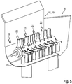
- the working member 6 has an elongated shaft 28, on the outer surface of which a plurality of fly blades 29 are arranged. These are hingedly attached to the shaft 28 , so that in the course of a rotation of the shaft 28 about a drive axis 30 of the working member 6, due to centrifugal forces acting, they are thrown radially outward.
- the kinetic energy acting in the course of the rotation of the shaft 28 is used to crush the residual material falling into the working element 6 by means of the fly knife 29 .
- the shaft 28 of the working member 6 extends over a width 8, which therefore represents the width 8 of the working member 6 .
- the guide element 7 By means of the guide element 7, it is now possible to distribute the Restgutstrom across the width 8 of the work organ 6, so that the working member 6 is charged across its width 8 away as uniformly as possible with Restgut.
- the result is that the chopped residual material is passed on to downstream ejection devices 9 in a distribution that takes place in equal parts, which in turn promotes uniform discharge of the residual material at the rear end of the combine harvester 1 .
- the combine harvester 1 comprises a total of two ejection devices 9, the are arranged side by side and the working element 6 are connected downstream.
- the position of the guide element 7 on the axial separator 2 has an indirect influence on the manner in which the residual material is distributed on the field in the course of its ejection from the combine harvester 1.
- a change in the position of the guide element 7 relative to the housing 4 of the axial separator 2 consequently leads to a change in the distribution of the residual material in the field.
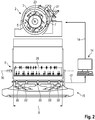
- the combine harvester 1 is equipped with a control circuit, which here comprises a sensor device 10 and a control unit 14 .
- the sensor device 10 is used to record data relating to an actual distribution of the residual material downstream of the axial separator 2 and to forward this data to the control unit 14 . This can take place in particular by means of a line 17 . However, wireless transmission of the data is equally possible.
- the recorded data can be processed by means of the control unit 14 , so that control commands for the guide element 7 can be generated.
- the latter is here connected to the control unit 14 by means of a line 18 , so that the control commands can be passed at least indirectly to the guide element 7 .
- the guide element 7 comprises an actuator 31 which is formed by an electrohydraulic cylinder.
- the actuator 31 can be controlled by means of the control unit 14 , so that the guide element 7 is moved. As a result of the feedback via the data recorded by means of the sensor device 10 , this movement can now be regulated in such a way that the distribution of the residual material discharged from the axial separator 2 changes over the width 8 of the downstream working element 6 .
- at least one predetermined target distribution is stored on the control unit 14 or a data memory thereof, which is comparable to an actual distribution detected by means of the sensor device 10 . In this way, a deviation of the actual distribution from the target distribution can be determined, as a result of which the control commands for the guide element 7 can be generated.
- the target distribution can in particular provide a balanced distribution ratio of the residual material flow to the two ejection devices 9 .
- the difference between the actual distribution and the target distribution is implemented by means of the control unit 14 to the effect that a control command is sent to the actuator 31 of the guide element 7 , as a result of which the guide element 7 is moved.
- This movement takes place in such a way that the deflection caused by the guide element 7 and the resulting distribution of the residual material flow on the working element 6 is changed in such a way that a larger proportion of the residual material flow is supplied to the right side of the working element 6 than before.
- the actual distribution of the residual material flow is approximated to the target distribution.
- the guide element 7 is continuously moved relative to the housing 3 of the axial separator 2 in order to continuously distribute the residual material flow over the width 8 of the working element 6 .
- the guide element 7 can perform a “pendulum” movement, in the course of which the guide element 7 is continuously moved between opposite extreme positions. This is particularly good based on the Figures 3 and 4th recognizable, in which the guide element 7 is shown in different positions, which in turn correspond to different distribution areas 24 over which the residual material flow exiting from the axial separator 2 is distributed.
- An oscillating movement of the guide element 7 is therefore particularly favorable to the working member 6 to feed continuously over its entire width 8 evenly with Restgut and thereby to achieve a corresponding equal-part feeding of the ejectors.
- control unit 14 it is possible in particular to control the actuator 31 of the guide element 7 in such a way that a movement characteristic of the guide element 7 is changed. This has the effect that from now on the flow of residual material is distributed in a different manner than was the case before the change in the movement characteristics.
- the intervention in the movement characteristics of the guide element 7 takes place in such a way that the deflection of the residual material flow by means of the guide element 7 leads to a distribution of the residual material flow to the working organ 6 that is at least closer to the target distribution than the actual distribution before the change in the Movement characteristics.
- the combine harvester 1 comprises a plurality of sensor devices 10 which are arranged at different measuring points 11, 12, 13 .
- a first sensor device 10 which is attached to a first Measuring point 11 is arranged in the incidence area 19 of the working organ 6.
- This sensor device 10, which is particularly good based on the Figures 5 and 6th results, is formed in the example shown as a measuring strip 21 which comprises a plurality of sensor elements 22 .
- These sensor elements 22 are arranged here distributed equidistantly over a length of the measuring bar 21 , the measuring bar 21 extending over the entire width 8 of the working member 6 .
- the plurality of sensor elements 22 the actual distribution of the residual material flow over the width 8 of the working organ 6 can be recorded particularly well.
- the combine harvester 1 comprises a further sensor device 10 at a second measuring point 12.
- the measuring point 12 is located on a floor panel 20 of the working element 6. This can be seen particularly well on the basis of FIG Figure 7 .
- the second sensor device 10 makes it particularly possible to collect data relating to the actual distribution of the residual material directly within the working organ 6 to capture. In this way, it is possible to take into account an influence of the working organ 6 on the actual distribution of the remaining material over the width 8 of the working organ 6 .
- the combine harvester 1 shown here has a third sensor device 10, which is likewise designed in the form of a measuring bar 21 . This is located at a measuring point 13 which is assigned to a distribution device 15 .
- the distribution device 15 is connected downstream of the two ejection devices 9 . It serves to distribute the residual material ejected by means of the ejection devices 9 over an ejection width which clearly exceeds a width of the rear end of the combine harvester 1 .
- the ejected stream of residual material is, so to speak, “fanned out” by means of the distribution device 15 , so that it is possible to distribute the residual material over an entire working width of the combine harvester 1 .
- the distribution device 15 which is particularly good based on the Figures 8 and 9 results, via a plurality of guide plates 16, by means of which the fanning of the residual material flow takes place.
- the sensor device 10 here comprises a total of five sensor elements 22, which are arranged equidistantly over a length of the measuring strip 21 .
- the sensor elements 22 it is possible to acquire data relating to the actual distribution of the residual material flow over a width of the distribution device 15 . In this way, data are recorded which characterize the actual distribution of the residual material flow immediately before it emerges from the combine harvester 1 .
- a plurality of guide plates 16 are in a particularly advantageous manner, each relative by means of an associated actuator, which is not shown in the figures adjustable to the rest of the distribution device 15 .
- the actuator is connected to the control unit 14 wirelessly, that is to say by means of a radio link.
- the combine harvester 1 according to the invention has a second control circuit, by means of which the actual distribution of the residual material in the area of the distribution device 15 is compared with a corresponding predetermined target distribution, control commands are generated and finally a position of the movable guide plates 16 is changed.
- any deviations in the actual distribution of the residual material from the target distribution in the distribution device 15 are compensated for by changing the ejection of the residual material by changing the position of the respective guide plates 16 , so that the deviations in the actual distribution be compensated for by the target distribution in the course of the ejection of the residual material flow and the residual material is ultimately deposited in the field in as homogeneous a distribution as possible.
- the combination of two control loops is particularly advantageous because in this way the actual distribution of the residual material can be regulated at several points, whereby the total flow of residual material on its way from the axial separator 2 to the ejection from the combine harvester 1 can be influenced in such a way that a homogeneous Distribution in the field can be achieved.
Abstract
Die vorliegende Anmeldung betrifft ein Verfahren zum Betrieb eines Mähdreschers (1), wobei ein Erntegutstrom mittels mindestens eines Axialabscheiders (2) bearbeitet und ein dadurch gebildeter Restgutstrom mittels mindestens zweier Auswurfeinrichtungen (9) aus dem Mähdrescher (1) ausgeworfen wird, wobei der Axialabscheider (2) ein bewegbares Leitelement (7) umfasst, mittels dessen der aus dem Axialabscheider (2) austretende Restgutstrom auf ein dem Axialabscheider (2) nachgeschaltetes Arbeitsorgan (6) verteilt wird.Um die Verteilung des Restgutstroms auf dem Feld weiter zu verbessern, wird erfindungsgemäß vorgeschlagen, dass eine Ist-Verteilung des Restgutstroms auf die zwei Auswurfeinrichtungen (9) erfasst wird, wobei bei Erfassung einer Abweichung der Ist-Verteilung von einer vorgegebenen Soll-Verteilung das Leitelement (7) derart nachgeregelt wird, dass die Ist-Verteilung der Soll-Verteilung zumindest angenähert wird.The present application relates to a method for operating a combine harvester (1), whereby a crop flow is processed by means of at least one axial separator (2) and a residual material flow thus formed is ejected from the combine harvester (1) by means of at least two ejection devices (9), the axial separator ( 2) comprises a movable guide element (7), by means of which the residual material flow emerging from the axial separator (2) is distributed to a working element (6) downstream of the axial separator (2). In order to further improve the distribution of the residual material flow in the field, the invention It is proposed that an actual distribution of the residual material flow to the two ejection devices (9) is recorded, with the guide element (7) being readjusted in such a way that the actual distribution of the target is readjusted when a deviation of the actual distribution from a predetermined target distribution is detected Distribution is at least approximated.
Description
Die vorliegende Anmeldung betrifft ein Verfahren zum Betrieb eines Mähdreschers gemäß dem Oberbegriff von Anspruch 1. Ferner betrifft die vorliegende Anmeldung einen selbstfahrenden Mähdrescher gemäß dem Oberbegriff von Anspruch 12.The present application relates to a method for operating a combine harvester according to the preamble of claim 1. Furthermore, the present application relates to a self-propelled combine harvester according to the preamble of claim 12.
Der Mähdrescher umfasst in aller Regel ein Dreschorgan, mittels dessen von geernteten Pflanzen Früchte ablösbar sind, die gesondert von verbleibenden Pflanzenresten der Pflanzen gewonnen werden sollen. Ein Gemisch von abgelösten Früchten und Pflanzenresten wird als Erntegutstrom ausgehend von dem Dreschorgan mindestens einem nachgeschalteten Axialabscheider zugeleitet. Dieser ist typischerweise derart ausgebildet, dass er ein Gehäuse umfasst, das einen kreisförmigen Querschnitt aufweist, sowie einen darin befindlichen, drehangetriebenen Axialrotor. Eine Längsachse des Axialrotors erstreckt sich parallel zu einer Mittelachse des Gehäuses. Mittels Betriebs des Axialrotors wird aus dem Erntegutstrom ein Gutanteil abgeschieden, der zumindest im Wesentlichen von den abgelösten Früchten gebildet ist. Der Erntegutstrom wird auf diese Weise in einen Restgutstrom überführt, der an einem rückwärtigen Ende des Mähdreschers ausgeworfen wird. Der Restgutstrom ist nach der Behandlung mittels des Axialabscheiders zumindest im Wesentlichen frei von Früchten. In bekannten Mähdreschern ist es üblich, dass mehrere Axialabscheider, insbesondere zwei Axialabscheider, parallel verwendet werden.The combine harvester usually comprises a threshing organ, by means of which fruits can be detached from harvested plants, which are to be obtained separately from remaining plant residues of the plants. A mixture of detached fruits and plant residues is fed as a crop flow from the threshing organ to at least one downstream axial separator. This is typically designed in such a way that it comprises a housing which has a circular cross section and a rotationally driven axial rotor located therein. A longitudinal axis of the axial rotor extends parallel to a central axis of the housing. By operating the axial rotor, a portion of the crop is separated from the crop flow, which is at least essentially formed by the detached fruits. In this way, the crop flow is converted into a residual flow which is ejected at a rear end of the combine harvester. After the treatment by means of the axial separator, the residual material flow is at least essentially free of fruit. In known combine harvesters, it is customary for several axial separators, in particular two axial separators, to be used in parallel.
Der Restgutstrom wird aus dem Axialabscheider an ein nachgeschaltetes Arbeitsorgan des Mähdreschers, insbesondere ein Häckselorgan, übergeben, wobei der Restgutstrom mittels mindestens eines bewegbaren Leitelements über eine Breite des Arbeitsorgans verteilt wird. Bei einer Ausgestaltung des Arbeitsorgans als Häckselorgan, weist das Arbeitsorgan typischerweise eine langgestreckte Abtriebswelle mit daran angeordneten Schlagmessern auf. Diese dienen dazu, den Restgutstrom zu bearbeiten, insbesondere zu zerkleinern bzw. zu häckseln. Dies ist insbesondere dann von Bedeutung, wenn das aus dem Mähdrescher abgeworfen Restgut nicht weiter verwertet werden soll, insbesondere nicht vom Feld aufgehoben und einem weiteren Verwendungszweck zugeführt werden soll. Die Zerkleinerung des Restguts ist vorteilhaft, um die biologische Zersetzung und die damit verbundene Rückführung von Nährstoffen in den Boden zu beschleunigen.The residual material flow is transferred from the axial separator to a downstream working element of the combine, in particular a chopping element, the residual material flow being distributed over a width of the working element by means of at least one movable guide element. When the working element is designed as a chopping element, the working element typically has an elongated output shaft with knives arranged on it. These serve to process the flow of residual material, in particular to shred or chop it. This is particularly important when the residual material thrown from the combine harvester is not to be used any further, in particular is not to be picked up from the field and used for a further purpose. The shredding of the residual material is advantageous in order to accelerate the biological decomposition and the associated return of nutrients into the soil.
Um grundsätzlich die Verteilung des Restgutstroms zu gewährleisten, umfasst der Mähdrescher mindestens zwei Auswurfeinrichtungen, an die der Restgutstrom stromabwärts des jeweilig dem Axialabscheider nachgeschalteten Arbeitsorgans übergeben wird. Typischerweise korrespondiert eine erste Auswurfeinrichtung mit einer linken Seite des Arbeitsorgans, die andere Auswurfeinrichtung mit der rechten Seite. Mittels der Auswurfeinrichtungen wird der Restgutstrom schließlich aus dem Mähdrescher ausgeworfen. Bei den Auswurfeinrichtungen kann es sich insbesondere um Radialgebläse handeln, mittels derer der Restgutstrom beschleunigt und sodann möglichst gleichmäßig auf dem Feld verteilt wird.In order to basically ensure the distribution of the residual material flow, the combine harvester comprises at least two ejection devices to which the residual material flow is transferred downstream of the respective working element downstream of the axial separator. Typically, a first ejection device corresponds to a left side of the working element, the other ejector device to the right side. Using the Ejection devices, the flow of residual material is finally ejected from the combine. The ejection devices can in particular be radial fans, by means of which the flow of residual material is accelerated and then distributed as evenly as possible over the field.
Ein Verfahren der vorstehend beschriebenen Art ist im Stand der Technik bereits bekannt. Hierzu wird beispielhaft auf die Europäische Patentschrift
Trotz derartiger Maßnahmen hat sich gezeigt, dass die Verteilung des Restgutstroms auf dem Feld weiter verbesserungswürdig ist. Dies betrifft insbesondere die Verteilung der in dem Restgutstrom vorhandenen restlichen Früchte, die nach Ablage auf dem Feld neu austreiben und ein Wurzelwerk ausbilden. Eine mangelnde Verteilung dieser restlichen Früchte führt dazu, dass streifenartige Bereiche auf dem Feld konzentriert mit restlichen Früchten beaufschlagt sind, wodurch der Boden in diesen Bereichen durch die sich ausbildenden Wurzeln befestigt wird. Die zu einem späteren Zeitpunkt stattfindende Bodenbearbeitung durch den Landwirt wird hierdurch erschwert. Es ist daher wünschenswert, den Restgutstrom mitsamt den darin enthaltenen Früchten möglichst homogen auf dem Feld zu verteilen, sodass lokale Befestigungen des Bodens möglichst schwach ausgeprägt sind.Despite such measures, it has been shown that the distribution of the flow of residual material in the field is in need of further improvement. This applies in particular to the distribution of the remaining fruits present in the flow of residual material, which sprout again after being deposited in the field and form a root system. Insufficient distribution of these remaining fruits leads to the fact that strip-like areas on the field are concentrated with remaining fruits, as a result of which the soil in these areas is secured by the roots that are forming. This makes it more difficult for the farmer to work the soil at a later point in time. It is therefore desirable to distribute the residual material flow, including the fruits contained therein, as homogeneously as possible over the field, so that local fortifications of the soil are as weak as possible.
Der vorliegenden Anmeldung liegt mithin die Aufgabe zugrunde, die Verteilung des Restgutstroms auf dem Feld weiter zu verbessern.The present application is therefore based on the object of further improving the distribution of the flow of residual material in the field.
Die zugrunde liegende Aufgabe wird erfindungsgemäß durch das Verfahren mit den Merkmalen des Anspruchs 1 gelöst. Vorteilhafte Ausgestaltungen ergeben sich aus den Unteransprüchen 2 bis 11.The underlying object is achieved according to the invention by the method having the features of claim 1. Advantageous refinements result from
Das erfindungsgemäße Verfahren ist dadurch gekennzeichnet, dass eine Ist-Verteilung des Restgutstroms auf mindestens zwei Auswurfeinrichtungen erfasst wird. Anschließend wird bei Feststellen einer Abweichung der erfassten Ist-Verteilung von einer vorgegebenen Soll-Verteilung das Leitelement des Axialabscheiders derart nachgeregelt, dass die Ist-Verteilung der Soll-Verteilung zumindest angenähert wird.The method according to the invention is characterized in that an actual distribution of the flow of residual material is recorded over at least two ejection devices. Subsequently, when a discrepancy between the recorded actual distribution and a specified target distribution is determined, the guide element of the axial separator is readjusted in such a way that the actual distribution is at least approximated to the target distribution.
Die Erfassung der Ist-Verteilung kann vorzugsweise mittels mindestens einer Sensoreinrichtung an mindestens einer Messstelle stromabwärts des Axialabscheiders erfolgen, wobei die Sensoreinrichtung Daten betreffend die Ist-Verteilung erfasst. Die auf diese Weise erfassten Daten werden sodann an eine Regeleinheit geleitet und mittels letzterer verarbeitet. Die Untersuchung auf die oben genannte Abweichung zwischen Ist- und Soll-Verteilung kann mittels einer solchen Regeleinheit besonders einfach bewerkstelligt werden.The actual distribution can preferably be recorded by means of at least one sensor device at at least one measuring point downstream of the axial separator, the sensor device recording data relating to the actual distribution. The data recorded in this way are then sent to a control unit and processed by the latter. The examination of the above-mentioned deviation between the actual and target distribution can be carried out particularly easily by means of such a control unit.
In einer beispielhaften Ausgestaltung ist es denkbar, dass in einem Übergabebereich zwischen einem als Häckselorgan ausgebildeten Arbeitsorgan und den mindestens zwei Auswurfeinrichtungen an mindestens einer Messstelle mittels einer Sensoreinrichtung Daten erfasst werden, anhand derer erkennbar ist, in welchem Verhältnis die beiden Auswurfeinrichtungen mit von dem Häckselorgan stammenden Restgut beschickt werden. Diese Daten beschreiben mithin die genannte Ist-Verteilung. Die vorgegebene Soll-Verteilung kann insbesondere ein ausgeglichenes Verteilverhältnis vorsehen, gemäß dessen das Restgut 50:50 aufgeteilt wird, sodass beide Auswurfeinrichtungen zu gleichen Teilen mit Restgut beschickt werden. Mittels der Sensoreinrichtung würde eine von dieser Soll-Verteilung abweichende Ist-Verteilung erfasst und an die Regeleinheit geleitet werden. Die Regeleinheit ist in diesem Beispiel dazu geeignet, in Abhängigkeit von der festgestellten Abweichung der Ist-Verteilung von der Soll-Verteilung Regelungsbefehle zu erzeugen und diese an das Leitelement zu übermitteln. Auf diese Weise wird das Leitelement derart nachgeregelt, dass die Ist-Verteilung der Soll-Verteilung zumindest angenähert wird. Mithin findet im Ergebnis eine Rückkopplung zwischen einer tatsächlichen Ist-Verteilung des Restgutstroms und der vorgegebenen Soll-Verteilung des Restgutstroms auf das Arbeitsorgan statt, die vorzugsweise fortwährend durchgeführt wird. Die Sensoreinrichtung, die Regeleinheit und das Leitelement bilden mithin einen Regelkreis. Eine Regelfrequenz des so gebildeten Regelkreises kann beispielsweise 10 Hz betragen. Andere Regelfrequenzen, sowohl höhere als auch niedrigere, sind gleichermaßen denkbar.In an exemplary embodiment, it is conceivable that in a transfer area between a working organ designed as a chopping organ and the at least two ejection devices at at least one measuring point, a sensor device can be used to record data which can be used to identify the ratio in which the two ejection devices come from the chopping device Remaining goods can be loaded. These data therefore describe the actual distribution mentioned. The specified target distribution can, in particular, provide a balanced distribution ratio, according to which the residual material is divided 50:50, so that both ejection devices are loaded with residual material in equal parts. By means of the sensor device, an actual distribution deviating from this target distribution would be recorded and sent to the control unit. In this example, the control unit is suitable for generating control commands as a function of the established deviation of the actual distribution from the target distribution and for transmitting these to the control element. In this way, the guide element is readjusted in such a way that the actual distribution is at least approximated to the target distribution. As a result, there is a feedback between an actual actual distribution of the flow of residual material and the predetermined target distribution of the flow of residual material to the working organ, which is preferably carried out continuously. The sensor device, the control unit and the guide element therefore form a control loop. A control frequency of the control loop formed in this way can be 10 Hz, for example. Other control frequencies, both higher and lower, are equally conceivable.
Das erfindungsgemäße Verfahren hat viele Vorteile. Insbesondere verhilft es dazu, die Verteilung des Restgutstroms zu optimieren, sodass das Restgut im Zuge des Auswurfs aus dem Mähdrescher möglichst gleichmäßig auf dem Feld verteilt wird. Insbesondere kann die Nachregelung des Leitelements einen unmittelbaren oder mittelbaren Einfluss auf die Ist-Verteilung des Restgutstroms nehmen, der sich sodann in der vorgegebenen Soll-Verteilung zumindest annähert, idealerweise die Soll-Verteilung erreicht. Dies hat zur Folge, dass die Verteilung des Restgutstroms auf dem Feld besonders gleichmäßig erfolgt.The method according to the invention has many advantages. In particular, it helps to optimize the distribution of the flow of residual material so that the residual material is distributed as evenly as possible over the field as it is ejected from the combine. In particular, the readjustment of the guide element can have a direct or indirect influence on the actual distribution of the residual material flow, which is then reflected in the specified target distribution at least approximately, ideally, the target distribution is achieved. The consequence of this is that the flow of residual material is distributed particularly evenly across the field.
In einer vorteilhaften Ausgestaltung des erfindungsgemäßen Verfahrens kann eine Regeleinheit verwendet werden, mittels der in Abhängigkeit von der Abweichung zwischen Ist- und Soll-Verteilung Regelungsbefehle erzeugt und mittelbar oder unmittelbar an das Leitelement geleitet werden. Insbesondere können die Regelungsbefehle an einen Aktor des Leitelements geleitet werden, mittels dessen das Leitelement angetrieben wird. In einer besonders vorteilhaften Ausgestaltung sind auf der Regeleinheiz (bzw. einem Datenspeicher derselben) Kennfelder hinterlegt, mittels derer Daten betreffend die Ist-Verteilung des Restgutstroms in Beziehung zu einer Bewegungscharakteristik des Leitelements gesetzt sind, sodass anhand solcher Kennfelder ableitbar ist, in welcher Weise die Bewegungscharakteristik des Leitelements verändert werden sollte, um die Ist-Verteilung in Richtung der angestrebten Soll-Verteilung zu verändern.In an advantageous embodiment of the method according to the invention, a control unit can be used by means of which control commands are generated as a function of the deviation between the actual and target distribution and are passed directly or indirectly to the control element. In particular, the control commands can be passed to an actuator of the guide element, by means of which the guide element is driven. In a particularly advantageous embodiment, characteristic fields are stored on the Regeleinheiz (or a data memory of the same), by means of which data relating to the actual distribution of the residual material flow are related to a movement characteristic of the guide element, so that it is possible to deduce from such characteristic fields in what way the Movement characteristics of the guide element should be changed in order to change the actual distribution in the direction of the desired target distribution.
Eine weiterhin vorteilhafte Ausgestaltung sieht vor, dass mittels einer Mehrzahl von Sensoreinrichtungen Daten betreffend die Ist-Verteilung des Restgutstroms erfasst werden. Vorzugsweise sind die Sensoreinrichtungen an verschiedenen Messstellen angeordnet. Auf diese Weise können Veränderungen der Ist-Verteilung des Restgutstroms besser beobachtet und entsprechende Regelungsbefehle für das Leitelement zielgerichteter sowie zeitnah erfolgen.A further advantageous embodiment provides that data relating to the actual distribution of the residual material flow are recorded by means of a plurality of sensor devices. The sensor devices are preferably arranged at different measuring points. In this way, changes in the actual distribution of the residual material flow can be better observed and corresponding control commands for the guide element can be given in a more targeted and timely manner.
Weiterhin kann eine solche Ausgestaltung des erfindungsgemäßen Verfahrens vorteilhaft sein, bei dem die Regelung des Leitelements automatisch erfolgt. Dies kann insbesondere in Abhängigkeit eines auf der Regeleinheit hinterlegten Regelungsalgorithmus geschehen, der in Abhängigkeit der erfassten Daten automatisch daraus abgeleitete Regelungsbefehle an das Leitelement übermittelt und auf diese Weise dessen Bewegung beeinflusst. Beispielsweise ist es denkbar, dass eine Bewegungsgeschwindigkeit des Leitelements verändert wird, sodass eine Verteilung des von dem Axialabscheider an ein als Häckselorgan ausgebildetes Arbeitsorgan übergebenen Restgutstroms verändert wird. Die Veränderung der Verteilung des Restgutstroms über die Breite des Häckselorgans hat dabei eine vorhersagbare Auswirkung auf die Verteilung des das Häckselorgan verlassenen Restgutstroms auf die nachgeschalteten Auswurfeinrichtungen. Beispielsweise ist es denkbar, dass bei einer Hanglage des zu bearbeitenden Feldes die Verteilung des Restgutstroms über die Breite des Häckselorgans infolge der wirkenden Schwerkraft asymmetrisch wird, sodass beispielsweise die linke Seite des Häckselorgans einen größeren Anteil des Restgutstroms erhält als die rechte Seite. Hierdurch würde sich eine ungleiche Beschickung der Auswurfeinrichtungen ergeben, was eine Abweichung von der Soll-Verteilung zur Folge hätte, die hier beispielhaft zu einem ausgeglichenen Verteilungsverhältnis zwischen den Auswurfeinrichtungen gewählt ist. Dieser ungleichen Beschickung der Auswurfeinrichtungen kann nunmehr mittels einer Veränderung der Bewegungscharakteristik des Leitelements entgegengesteuert werden. Letzteres kann beispielsweise derart bewegt werden, dass es den Restgutstrom vermehrt in Richtung der rechten Seite des Häckselorgans lenkt, sodass die beiden Hälften des Häckselorgans (und infolgedessen die beiden Auswurfeinrichtungen) möglichst gleichmäßig mit Restgut beschickt werden. Die automatische Regelung des Leitelements macht einen Eingriff eines Maschinenführers entbehrlich, wobei insbesondere eine fortwährende Regelung des Leitelements erfolgen kann. Der erfindungsgemäße Regelkreis kann auf diese Weise mit einer hohen Abtastrate betrieben werden, sodass die Ist-Verteilung fortwährend beeinflusst wird mit der Zielsetzung, die vorgegebene Soll-Verteilung zu erhalten.Furthermore, such an embodiment of the method according to the invention can be advantageous in which the control of the guide element takes place automatically. This can take place in particular as a function of a control algorithm stored on the control unit, which, as a function of the recorded data, automatically transmits control commands derived therefrom to the control element and in this way influences its movement. For example, it is conceivable that a movement speed of the guide element is changed, so that a distribution of the residual material flow transferred from the axial separator to a working element designed as a chopping element is changed. The change in the distribution of the residual material flow over the width of the chopping element has a predictable effect on the distribution of the residual material flow leaving the chopping element on the downstream ejection devices. For example, it is conceivable that if the field to be processed is on a slope, the distribution of the residual material flow across the width of the chopping element becomes asymmetrical as a result of the force of gravity, so that, for example, the left side of the chopping element receives a larger proportion of the residual material flow than the right side. This would result in an uneven loading of the ejection devices, which would result in a deviation from the target distribution would result, which is selected here as an example for a balanced distribution ratio between the ejection devices. This uneven loading of the ejection devices can now be counteracted by changing the movement characteristics of the guide element. The latter can be moved, for example, in such a way that it increasingly directs the flow of residual material towards the right side of the chopping element so that the two halves of the chopping element (and consequently the two ejection devices) are charged with residual material as evenly as possible. The automatic regulation of the guide element makes intervention by a machine operator superfluous, it being possible, in particular, to continuously regulate the guide element. In this way, the control loop according to the invention can be operated at a high sampling rate, so that the actual distribution is continuously influenced with the aim of obtaining the specified target distribution.
In besonders vorteilhafter Weise werden die Daten betreffend die Ist-Verteilung des Restgutstroms fortwährend erfasst, vorzugsweise mit einer Frequenz von mindestens 10 Hz. Entsprechend kann es besonders vorteilhaft sein, wenn dem Leitelement fortwährend Regelungsbefehle zugeleitet werden, wobei insbesondere eine Bewegungsgeschwindigkeit des Leitelements fortwährend verändert wird. Die Verteilung des Restgutstroms auf das Feld unterliegt bei einem solchen Vorgehen einer dauerhaften Überwachung, die bei Erfassung von Abweichungen zwischen der Ist-Verteilung und der vorgegebenen Soll-Verteilung unmittelbar in Konsequenzen erwächst, sodass die Abweichung zumindest reduziert wird.In a particularly advantageous manner, the data relating to the actual distribution of the residual material flow is continuously recorded, preferably at a frequency of at least 10 Hz. Accordingly, it can be particularly advantageous if control commands are continuously sent to the guide element, with a particular movement speed of the guide element being continuously changed . With such a procedure, the distribution of the residual material flow in the field is subject to permanent monitoring, which is a direct consequence of the detection of deviations between the actual distribution and the specified target distribution, so that the deviation is at least reduced.
In einer besonders vorteilhaften Ausgestaltung des erfindungsgemäßen Verfahrens werden über die Ist-Verteilung des Restgutstroms hinaus weitere Daten erfasst. Diese können insbesondere eine Art des jeweiligen Ernteguts, herrschende Erntebedingungen, Maschinendaten des Mähdreschers und/oder eine Soll-Schwadbreite des ausgeworfenen Restgutstroms betreffen. Daten betreffend das jeweilige Erntegut können beispielsweise vor Erntebeginn von einem Maschinenführer des Mähdreschers eingegeben werden, wobei sich diese Information während eines Erntevorgangs in der Regel nicht verändert. Erntebedingungen wie beispielsweise Witterungsbedingungen (Wind, Regen etc.), Umgebungsbedingungen (Neigung des Feldes, Bodenbeschaffenheit etc.), Betriebsbedingungen des Mähdreschers (Fahrgeschwindigkeit, angestrebter Restkornanteil etc.) können jeweils individuell einmalig, periodisch oder durchgehend erhoben werden. Die Maschinendaten des Mähdreschers sind in aller Regel während eines laufenden Erntevorgangs unverändert. Daten betreffend die Soll-Schwadbreite können insbesondere von dem Maschinenführer vorgegeben werden, worauf hin sie entsprechend berücksichtigt werden können. Derartige zusätzliche Daten können insbesondere mittels einer Regeleinheit verarbeitet werden, sodass sie für die Erzeugung von Regelungsbefehlen für das Leitelement zusätzlich berücksichtigt werden können. Hierdurch kann die Verteilung des Restguts auf dem Feld weiter verbessert werden.In a particularly advantageous embodiment of the method according to the invention, further data are recorded beyond the actual distribution of the residual material flow. These can in particular relate to a type of crop, prevailing harvesting conditions, machine data of the combine and / or a target swath width of the ejected residual crop flow. Data relating to the respective crop can, for example, be entered by a machine operator of the combine before the start of the harvest, this information generally not changing during a harvesting process. Harvest conditions such as weather conditions (wind, rain, etc.), environmental conditions (inclination of the field, soil conditions, etc.), operating conditions of the combine harvester (driving speed, desired residual grain percentage, etc.) can each be recorded individually, periodically or continuously. The machine data of the combine harvester are usually unchanged while the harvesting process is in progress. Data relating to the desired swath width can in particular be specified by the machine operator, whereupon they can be taken into account accordingly. Additional data of this kind can in particular by means of a control unit processed so that they can also be taken into account for the generation of control commands for the control element. This can further improve the distribution of the remaining material on the field.
Neben einer Regelung des mindestens einen Leitelements des mindestens einen Axialabscheiders kann es zudem vorteilhaft sein, wenn die Regeleinheit Regelungsbefehle für mindestens ein Verteilblech einer den Auswurfeinrichtungen nachgeschalteten Verteileinrichtung erzeugt und an das jeweilige Verteilblech leitet. Letzteres ist bewegbar relativ zu der restlichen Verteileinrichtung angeordnet, sodass sich mittels einer Bewegung des Leitelements eine Auswurfcharakteristik des Restgutstroms verändert. Die Verteileinrichtung umfasst eine Mehrzahl von Verteilblechen, die dazu geeignet sind, den von den Auswurfeinrichtungen abgegebenen Restgutstrom aufzufächern. Dies ist in aller Regel erforderlich, um den Restgutstrom über eine Breite zu verteilen, die eine Breite des rückwärtigen Endes des Mähdreschers deutlich übersteigt. Insbesondere ist es gewünscht, den Restgutstrom über die Breite eines Schneidwerks des Mähdreschers zu verteilen, da letzteres eine Arbeitsbreite des Mähdreschers definiert. Eine gleichmäßige Verteilung des Restgutstroms über die Arbeitsbreite des Mähdreschers würde mithin die Fläche des jeweiligen Feldes, auf dem der Restgutstrom abgelegt wird, vollständig ausschöpfen. Dies ist zu begrüßen, um die Dichte von in dem Restgutstrom verbliebenen Früchten pro Flächenanteil des Feldes zu minimieren.In addition to regulating the at least one guide element of the at least one axial separator, it can also be advantageous if the regulating unit generates control commands for at least one distributor plate of a distributor device downstream of the ejection devices and forwards them to the respective distributor plate. The latter is arranged to be movable relative to the rest of the distribution device, so that a movement of the guide element changes an ejection characteristic of the residual material flow. The distribution device comprises a plurality of distribution plates which are suitable for fanning out the stream of residual material discharged by the ejection devices. This is usually necessary in order to distribute the flow of residual material over a width which clearly exceeds a width of the rear end of the combine harvester. In particular, it is desirable to distribute the flow of residual material over the width of a cutting unit of the combine harvester, since the latter defines a working width of the combine harvester. A uniform distribution of the flow of residual material over the working width of the combine harvester would therefore completely utilize the area of the respective field on which the flow of residual material is deposited. This is to be welcomed in order to minimize the density of fruit remaining in the flow of residual material per area of the field.
Bei Vorhandensein einer vorstehend beschriebenen Verteileinrichtung ist es zudem vorteilhaft, wenn an bzw. in der Verteileinrichtung mindestens eine Messstelle angeordnet ist, an der mittels mindestens einer Sensoreinrichtung Daten betreffend eine Ist-Verteilung des Restgutstroms erfasst werden. Diese können sodann mittels einer Regeleinheit mit einer vorgegebenen Soll-Verteilung verglichen werden, woraufhin die Regeleinheit für das mindestens eine verstellbare Verteilblech Regelungsbefehle erzeugt und diese mittelbar oder unmittelbar an das Verteilblech leitet. Das Verteilblech kann hierdurch relativ zu der übrigen Verteileinrichtung bewegt werden, sodass sich die Verteilung des Restgutstroms in Richtung der Soll-Verteilung zumindest annähert. Zwecks Bewegung des Verteilblechs kann selbiges beispielsweise mit einem elektrischen oder hydraulischen Aktor zusammenwirken.In the presence of a distribution device described above, it is also advantageous if at least one measuring point is arranged on or in the distribution device, at which data relating to an actual distribution of the residual material flow are recorded by means of at least one sensor device. These can then be compared with a predetermined target distribution by means of a control unit, whereupon the control unit generates control commands for the at least one adjustable distribution plate and directs them directly or indirectly to the distribution plate. As a result, the distribution plate can be moved relative to the rest of the distribution device, so that the distribution of the flow of residual material at least approximates the target distribution. In order to move the distributor plate, it can interact with an electrical or hydraulic actuator, for example.
In vorrichtungstechnischer Hinsicht wird die zugrunde liegende Aufgabe mittels eines Mähdreschers mit den Merkmalen des Anspruchs 12 gelöst. Vorteilhafte Ausgestaltungen ergeben sich aus den Unteransprüchen 13 bis 16. Der erfindungsgemäße Mähdrescher umfasst mindestens eine Sensoreinrichtung, mittels der Daten betreffend eine Ist-Verteilung des Restgutstroms auf die mindestens zwei Auswurfeinrichtungen erfassbar sind. Ferner umfasst der erfindungsgemäße Mähdrescher mindestens eine Regeleinheit, mittels der von der Sensoreinrichtung erfasste Daten verarbeitbar sind. Die Sensoreinrichtung und die Regeleinheit sind in Daten übertragender Weise miteinander verbunden, beispielsweise mittels einer körperlichen Leitung oder kabellos, sodass Daten von der Sensoreinrichtung an die Regeleinheit leitbar sind. Ebenso sind die Regeleinheit und das Leitelement in Daten übertragender Weise miteinander verbunden, sodass Regelungsbefehle von der Regeleinheit mittelbar oder unmittelbar an das Leitelement leitbar sind. Insbesondere kann das Leitelement mit einem Aktor zusammenwirken, der die Regelungsbefehle erhält und entsprechend eine Bewegung des Leitelements vornimmt.In terms of device technology, the underlying object is achieved by means of a combine harvester with the features of claim 12. Advantageous refinements emerge from the
Das erfindungsgemäße Verfahren ist mittels des erfindungsgemäßen Mähdreschers besonders einfach umsetzbar. Die sich hierdurch ergebenden Vorteile sind vorstehend bereits dargelegt. Insbesondere wird die Möglichkeit geschaffen, eine Ist-Verteilung des Restgutstroms an eine Soll-Verteilung zumindest anzunähern, sodass eine gegenüber dem Stand der Technik gleichmäßigere Verteilung des Restgutstroms auf dem Feld erzielt werden kann.The method according to the invention is particularly easy to implement by means of the combine harvester according to the invention. The advantages resulting from this have already been set out above. In particular, the possibility is created of at least approximating an actual distribution of the residual material flow to a target distribution, so that a more uniform distribution of the residual material flow in the field can be achieved compared to the prior art.
Den erfindungsgemäßen Mähdrescher weiter ausgestaltend ist mindestens eine Sensoreinrichtung an mindestens einer Messstelle in einem Einfallbereich eines als Häckselorgan ausgebildeten Arbeitsorgans angeordnet. Der Einfallbereich des Häckselorgans beschreibt denjenigen Bereich, in den das von dem Axialabscheider stammende Restgut in das Häckselorgan einfällt. Mittels der Anordnung der Sensoreinrichtung an dieser Messstelle wird die Möglichkeit geschaffen, die Verteilung des Restgutstroms über eine Breite des Häckselorgans hinweg zu erfassen.In a further development of the combine harvester according to the invention, at least one sensor device is arranged at at least one measuring point in an area of incidence of a working organ designed as a chopping organ. The area of incidence of the chopping element describes that area in which the residual material from the axial separator falls into the chopping element. The arrangement of the sensor device at this measuring point creates the possibility of detecting the distribution of the residual material flow over a width of the chopping element.
Alternativ oder zusätzlich kann mindestens eine Sensoreinrichtung an mindestens einer Messstelle an bzw. in einem Bodenblech eines solchen Häckselorgans angeordnet sein. Mittels Anordnung einer Sensoreinrichtung an einer solchen Messstelle wird die Möglichkeit geschaffen, die Verteilung des Restgutstroms innerhalb des Häckselorgans zu erfassen. Die Kombination dieser Messstelle mit der vorstehend beschriebenen Messstelle in dem Einfallbereich des Häckselorgans ist besonders vorteilhaft, um eine Verteilung des Restgutstroms über die Breite des Häckselorgans dynamisch verfolgen zu können. Insbesondere können durch den Betrieb des Häckselorgans bedingte Wanderungen des Restgutstroms in Breitenrichtung des Häckselorgans stattfinden, die bei alleiniger Erfassung von Daten betreffend die Ist-Verteilung des Restgutstroms beispielsweise in dem Einfallbereich des Häckselorgans nicht berücksichtigt werden könnten.Alternatively or additionally, at least one sensor device can be arranged at at least one measuring point on or in a base plate of such a chopping element. By arranging a sensor device at such a measuring point, it is possible to detect the distribution of the residual material flow within the chopping element. The combination of this measuring point with the above-described measuring point in the incidence area of the chopping organ is particularly advantageous in order to be able to dynamically track a distribution of the residual material flow over the width of the chopping organ. In particular, wandering of the residual material flow in the width direction of the chopping element caused by the operation of the chopping element can take place, which could not be taken into account if only data relating to the actual distribution of the residual material flow, for example, in the incidence area of the chopping element were recorded.
Schließlich kann es weiterhin vorteilhaft sein, mindestens eine Sensoreinrichtung an mindestens einer Messstelle an einer Verteileinrichtung anzuordnen, die den Auswurfeinrichtungen nachgeschaltet ist. Die Anordnung einer Sensoreinrichtung an dieser Messstelle kann zusätzlich oder alternativ zu den vorgenannten Messstellen erfolgen. In besonders vorteilhafter Weise sind Sensoreinrichtungen an allen drei beschriebenen Messstellen angeordnet. Die in der Verteileinrichtung angeordnete Messstelle bietet den besonderen Vorteil, dass die dort erfassten Daten eine Aussage über die Ist-Verteilung des Restgutstroms unmittelbar vor dem Verlassen des Mähdreschers ermöglichen. Eine Veränderung der Bewegungscharakteristik des Leitelements hat auf die Ist-Verteilung des Restgutstroms in der Verteileinrichtung lediglich einen mittelbaren Einfluss, erlaubt jedoch das Aufdecken von Korrelationen zwischen Veränderungen der Bewegungscharakteristik des Leitelements und der Verteilung des Restgutstroms in der Verteileinrichtung. Zudem ermöglicht die Anordnung mindestens einer Sensoreinrichtung in der Verteileinrichtung die Regelung mindestens eines Verteilblechs der Verteileinrichtung, wie vorstehend beschrieben ist.Finally, it can furthermore be advantageous to arrange at least one sensor device at at least one measuring point on a distribution device, which the Ejection devices is downstream. A sensor device can be arranged at this measuring point in addition to or as an alternative to the aforementioned measuring points. In a particularly advantageous manner, sensor devices are arranged at all three described measuring points. The measuring point arranged in the distribution device offers the particular advantage that the data recorded there enable a statement to be made about the actual distribution of the residual material flow immediately before leaving the combine harvester. A change in the movement characteristics of the guide element only has an indirect influence on the actual distribution of the residual material flow in the distribution device, but allows correlations to be discovered between changes in the movement characteristics of the guide element and the distribution of the residual material flow in the distribution device. In addition, the arrangement of at least one sensor device in the distribution device enables the regulation of at least one distribution plate of the distribution device, as described above.
Die Erfassung von Daten an mehreren Messstellen ermöglicht gewissermaßen eine Nachverfolgung des Restguts ausgehend von dem Axialabscheider bis zum Verlassen des Mähdreschers. Der Einfluss einer Veränderung der Bewegungscharakteristik des Leitelements kann auf diese Weise besonders gut nachverfolgt werden.The acquisition of data at several measuring points enables, as it were, a tracking of the residual material starting from the axial separator until it leaves the combine harvester. The influence of a change in the movement characteristics of the guide element can be tracked particularly well in this way.
Schließlich ist ein solcher Mähdrescher besonders vorteilhaft, bei dem mindestens eine Sensoreinrichtung in Form einer Messleiste ausgebildet ist. Eine solche Messleiste umfasst eine Mehrzahl voneinander beabstandeter Sensorelemente, die vorzugsweise äquidistant entlang der Messleiste verteilt angeordnet sind. Insbesondere ist es denkbar, dass eine als Messleiste ausgebildete Sensoreinrichtung sich jeweils über eine Breite eines jeweilig überwachten Bereichs hinweg erstreckt, sodass eine Querverteilung des Restguts in dem jeweiligen Bereich erfassbar ist. Bei einer beispielsweise in dem Einfallbereich eines Häckselorgans angeordneten Sensoreinrichtung kann sich die als Messleiste ausgebildete Sensoreinrichtung über die Breite des Häckselorgans hinweg erstrecken, wobei eine Mehrzahl, beispielsweise fünf, Sensorelemente über die Länge der Messleiste hinweg verteilt angeordnet sind. Auf diese Weise erfasste Daten sind besonders gut geeignet, die Ist-Verteilung des Restgutstroms zu beurteilen. Bei Zurverfügungstellen derartiger Daten kann die Regeleinheit besonders zielgerichtete Regelungsbefehle für das Leitelement erzeugen sowie Veränderungen der Ist-Verteilung infolge der Regelungsbefehle nachverfolgen.Finally, such a combine harvester is particularly advantageous in which at least one sensor device is designed in the form of a measuring strip. Such a measuring strip comprises a plurality of spaced apart sensor elements, which are preferably arranged equidistantly distributed along the measuring strip. In particular, it is conceivable that a sensor device embodied as a measuring strip extends over a width of a respective monitored area, so that a transverse distribution of the residual material in the respective area can be detected. In the case of a sensor device arranged, for example, in the incidence area of a chopping element, the sensor device designed as a measuring bar can extend over the width of the chopping element, with a plurality, for example five, sensor elements being arranged distributed over the length of the measuring bar. Data recorded in this way are particularly well suited to assessing the actual distribution of the residual material flow. When such data is made available, the control unit can generate particularly targeted control commands for the control element and track changes in the actual distribution as a result of the control commands.
Die Erfindung ist nachstehend anhand eines Ausführungsbeispiels, das in den Figuren dargestellt ist, näher erläutert. Es zeigt:
- Fig. 1:
- Einen Querschnitt durch einen erfindungsgemäßen Mähdrescher,
- Fig. 2:
- Eine schematische Ansicht eines rückwärtigen Endes eines Axialabscheiders sowie eines als Häckselorgan ausgebildeten, nachgeschalteten Arbeitsorgans,
- Fig. 3:
- Eine schematische Ansicht einer Restgutverteilung ausgehend von dem Axialabscheider an das Häckselorgan bei Vorliegen eines Leitelements in einer ersten Stellung,
- Fig. 4:
- die schematische Ansicht gemäß
Figur 3 , wobei das Leitelement in einer zweiten Stellung vorliegt, - Fig. 5:
- Eine perspektivische Ansicht des Häckselorgans, wobei in einem Einfallbereich des Häckselorgans eine Sensoreinrichtung angeordnet ist,
- Fig. 6:
- Eine Rückansicht des Häckselorgans gemäß
Figur 5 , - Fig. 7:
- Eine perspektivische Ansicht eines Bodenbereichs des Häckselorgans, wobei in einem Bodenblech des Häckselorgans eine Sensoreinrichtung angeordnet ist,
- Fig. 8:
- Eine perspektivische Ansicht einer Verteileinrichtung, die mit einer Sensoreinrichtung ausgestattet ist und
- Fig. 9:
- eine weitere Ansicht der Verteileinrichtung gemäß
Figur 8
- Fig. 1:
- A cross section through a combine harvester according to the invention,
- Fig. 2:
- A schematic view of a rear end of an axial separator and a downstream working element designed as a chopping element,
- Fig. 3:
- A schematic view of a residual material distribution proceeding from the axial separator to the chopping element with a guide element in a first position,
- Fig. 4:
- the schematic view according to
Figure 3 , the guide element being in a second position, - Fig. 5:
- A perspective view of the chopping element, a sensor device being arranged in an incidence area of the chopping element,
- Fig. 6:
- A rear view of the chopper organ according to
Figure 5 , - Fig. 7:
- A perspective view of a bottom area of the chopping element, a sensor device being arranged in a bottom plate of the chopping element,
- Fig. 8:
- A perspective view of a distribution device, which is equipped with a sensor device and
- Fig. 9:
- a further view of the distribution device according to
Figure 8 .
Ein Ausführungsbeispiel, das in den
Die Abscheidung der Früchte erfolgt mittels eines um seine Längsachse 23 drehantreibbaren Axialrotors 5, der innerhalb eines Gehäuses 3 des Axialabscheiders 2 gelagert ist. An einem dem Dreschorgan 3 abgewandten rückwärtigen Ende des Axialabscheiders 2 umfasst selbiger ein Leitelement 7, das hier von einem Leitblech gebildet ist, das einer Krümmung des Gehäuses 3 entsprechend gekrümmt ausgebildet ist. Das Leitelement 7 ist bewegbar relativ zu dem Gehäuse 3 ausgebildet und wirkt zu diesem Zweck mit einem elektrohydraulischen Aktor 31 zusammen, mittels dessen das Leitelement 7 antreibbar ist. Der den Axialabscheider 2 verlassende Restgutstrom, der innerhalb des Gehäuses 3 spiralförmig bzw. wendelförmig geführt wird, verlässt den Axialabscheider 2 schwerpunktmäßig an einem begrenzten Umfangsbereich des Gehäuses 3. Das Leitelement 7 ist diesem Umfangsbereich zugeordnet, sodass das Leitelement 7 eine Strömung des Restgutstroms beeinflussen kann. Insbesondere ragt das Leitelement 7 in einen Strömungsbereich des Restgutstroms hinein, sodass der Restgutstrom beim Verlassen des Axialabscheiders 2 auf das Leitelement 7 treffen kann und hierdurch umlenkbar ist. Mittels Bewegung des Leitelements 7 relativ zu dem Gehäuse 3 kann der Einfluss des Leitelements 7 auf die Art bzw. die Intensität der Umlenkung des Restgutstroms verändert werden. Dies hat zur Folge, dass der Restgutstrom in Abhängigkeit von einer Stellung des Leitelements 7 in unterschiedlicher Art und Weise an ein dem Axialabscheider 2 nachgeschaltetes Arbeitsorgan 6 übergeben wird. Letzteres ist hier als Häckselorgan ausgebildet.The fruits are separated off by means of an
Das Arbeitsorgan 6 ist vertikal unterhalb des Axialabscheiders 2 angeordnet, sodass das aus dem Axialabscheider 2 abgegebene Restgut gewissermaßen in das Arbeitsorgan 6 fällt. Das Arbeitsorgan 6 verfügt über eine langgestreckte Welle 28, an deren äußerer Mantelfläche eine Vielzahl von Schlagmessern 29 angeordnet sind. Diese sind gelenkig an der Welle 28 befestigt, sodass sie im Zuge einer Rotation der Welle 28 um eine Antriebsachse 30 des Arbeitsorgans 6 aufgrund wirkender Fliehkräfte radial nach außen geschleudert werden. Die im Zuge der Rotation der Welle 28 wirkende kinetische Energie wird dazu verwendet, um mittels der Schlagmesser 29 das in das Arbeitsorgan 6 herabfallende Restgut zu zerkleinern. Die Welle 28 des Arbeitsorgans 6 erstreckt sich über eine Breite 8, die mithin die Breite 8 des Arbeitsorgans 6 darstellt. Mittels des Leitelements 7 ist es nunmehr möglich, den Restgutstrom über die Breite 8 des Arbeitsorgans 6 zu verteilen, sodass das Arbeitsorgan 6 über seine Breite 8 hinweg möglichst gleichmäßig mit Restgut beschickt wird. Hieraus ergibt sich, dass eine Weitergabe des gehäckselten Restguts an nachgeschaltete Auswurfeinrichtungen 9 gleichermaßen in einer zu gleichen Teilen stattfindenden Verteilung erfolgt, wodurch wiederum ein gleichmäßiger Abwurf des Restguts an dem rückwärtigen Ende des Mähdreschers 1 begünstigt wird. In dem vorliegenden Beispiel umfasst der Mähdrescher 1 insgesamt zwei Auswurfeinrichtungen 9, die nebeneinander angeordnet sind und dem Arbeitsorgan 6 nachgeschaltet sind. Im Ergebnis hat die Stellung des Leitelements 7 an dem Axialabscheider 2 einen mittelbaren Einfluss darauf, in welcher Weise das Restgut im Zuge seines Auswurfs aus dem Mähdrescher 1 auf dem Feld verteilt wird. Eine Veränderung der Stellung des Leitelements 7 relativ zu dem Gehäuse 4 des Axialabscheiders 2 führt folglich dazu, dass sich auch die Verteilung des Restguts auf dem Feld verändert.The working element 6 is arranged vertically below the
Der Mähdrescher 1 ist mit einem Regelkreis ausgestattet, der hier eine Sensoreinrichtung 10 sowie eine Regeleinheit 14 umfasst. Die Sensoreinrichtung 10 dient dazu, Daten betreffend eine Ist-Verteilung des Restguts stromabwärts des Axialabscheiders 2 zu erfassen und diese Daten an die Regeleinheit 14 weiterzuleiten. Dies kann insbesondere mittels einer Leitung 17 erfolgen. Eine kabellose Übertragung der Daten ist jedoch gleichermaßen möglich. Die erfassten Daten sind mittels der Regeleinheit 14 verarbeitbar, sodass Regelungsbefehle für das Leitelement 7 erzeugbar sind. Letzteres ist hier mittels einer Leitung 18 mit der Regeleinheit 14 verbunden, sodass die Regelungsbefehle zumindest mittelbar an das Leitelement 7 leitbar sind. Das Leitelement 7 umfasst einen Aktor 31, der hiervon einem elektrohydraulischen Zylinder gebildet ist. Der Aktor 31 ist mittels der Regeleinheit 14 ansteuerbar, sodass das Leitelement 7 bewegt wird. Diese Bewegung kann nunmehr infolge der Rückkopplung über die mittels der Sensoreinrichtung 10 erfassten Daten derart geregelt werden, dass sich die Verteilung des aus dem Axialabscheider 2 abgegebenen Restguts über die Breite 8 des nachgeschalteten Arbeitsorgans 6 verändert. Insbesondere ist auf der Regeleinheit 14 bzw. einem Datenspeicher derselben mindestens eine vorgegebene Soll-Verteilung gespeichert, die mit einer mittels der Sensoreinrichtung 10 erfassten Ist-Verteilung vergleichbar ist. Auf diese Weise ist eine Abweichung der Ist-Verteilung von der Soll-Verteilung ermittelbar, infolge der die Regelungsbefehle für das Leitelement 7 erzeugbar sind. Die Soll-Verteilung kann insbesondere ein ausgeglichenes Verteilverhältnis des Restgutstroms auf die beiden Auswurfeinrichtungen 9 vorsehen.The combine harvester 1 is equipped with a control circuit, which here comprises a
Somit ist es beispielsweise denkbar, dass mittels einer Sensoreinrichtung 10, die an einer Messstelle 11 in einem Einfallbereich 19 des Arbeitsorgans 6 angeordnet ist, festgestellt wird, dass die linke Seite des Arbeitsorgans 6 einen größeren Anteil des von dem Axialabscheider 2 übergebenen Restgutstroms erhält als die rechte Seite. Dies hat zur Folge, dass die Ist-Verteilung des Restgutstroms auch beim Austritt aus dem Arbeitsorgan 6 und mithin bei Übergabe an die Auswurfeinrichtungen 9 asymmetrisch ist. Die vorgegebene Soll-Verteilung sieht jedoch eine gleichmäßige Verteilung des Restgutstroms an beide Auswurfeinrichtungen 9 vor. Der Unterschied zwischen der Ist-Verteilung und der Soll-Verteilung wird mittels der Regeleinheit 14 dahingehend umgesetzt, dass ein Regelungsbefehl an den Aktor 31 des Leitelements 7 geleitet wird, infolgedessen das Leitelement 7 bewegt wird. Diese Bewegung erfolgt derart, dass die mittels des Leitelements 7 bewirkte Ablenkung und die sich daraus ergebende Verteilung des Restgutstroms auf das Arbeitsorgan 6 dahingehend verändert wird, dass der rechten Seite des Arbeitsorgans 6 ein größerer Anteil des Restgutstroms zugeleitet wird als zuvor. In mittelbarer Folge dieses Eingriffs wird die Ist-Verteilung des Restgutstroms an die Soll-Verteilung angenähert.Thus, it is for example conceivable that it is determined by means of a
In besonders vorteilhafter Weise wird das Leitelement 7 fortwährend relativ zu dem Gehäuse 3 des Axialabscheiders 2 bewegt, um den Restgutstrom kontinuierlich über die Breite 8 des Arbeitsorgans 6 zu verteilen. Insbesondere kann das Leitelement 7 eine "pendelnde" Bewegung ausführen, in deren Zuge das Leitelement 7 fortwährend zwischen einander gegenüberliegenden extremalen Stellungen bewegt wird. Dies ist besonders gut anhand der
Mittels der Regeleinheit 14 ist es insbesondere möglich, den Aktor 31 des Leitelements 7 derart anzusteuern, dass eine Bewegungscharakteristik des Leitelements 7 verändert wird. Hierdurch wird der Effekt erzielt, dass der Restgutstrom fortan auf andere Art und Weise verteilt wird, als dies vor der Veränderung der Bewegungscharakteristik der Fall war. Der Eingriff in die Bewegungscharakteristik des Leitelements 7 erfolgt dabei derart, dass die Ablenkung des Restgutstroms mittels des Leitelements 7 zu einer Verteilung des Restgutstroms auf das Arbeitsorgan 6 führt, die zumindest näher an der Soll-Verteilung ist als die Ist-Verteilung vor der Veränderung der Bewegungscharakteristik. Da Daten betreffend die Verteilung des Restgutstroms mittels der Sensoreinrichtung 10 fortwährend erfasst werden, kann entsprechend eine fortwährende Anpassung der Bewegungscharakteristik des Leitelements 7 stattfinden, deren Einfluss sodann unmittelbar wieder geprüft wird. Folglich bilden die Sensoreinrichtung 10, die Regeleinheit 14 und das Leitelement 7 einen Regelkreis.By means of the
In dem gezeigten Beispiel umfasst der Mähdrescher 1 eine Mehrzahl von Sensoreinrichtungen 10, die an verschiedenen Messstellen 11, 12, 13 angeordnet sind. Vorstehend bereits beschrieben ist eine erste Sensoreinrichtung 10, die an einer ersten Messstelle 11 im Einfallbereich 19 des Arbeitsorgans 6 angeordnet ist. Diese Sensoreinrichtung 10, die sich besonders gut anhand der
Weiterhin umfasst der Mähdrescher 1 an einer zweiten Messstelle 12 eine weitere Sensoreinrichtung 10. Die Messstelle 12 befindet sich dabei an einem Bodenblech 20 des Arbeitsorgans 6. Dies ergibt sich besonders gut anhand von
Schließlich verfügt der hier gezeigte Mähdrescher 1 über eine dritte Sensoreinrichtung 10, die gleichermaßen in Form einer Messleiste 21 ausgebildet ist. Diese befindet sich an einer Messstelle 13, die einer Verteileinrichtung 15 zugeordnet ist. Die Verteileinrichtung 15 ist den beiden Auswurfeinrichtungen 9 nachgeschaltet. Sie dient dazu, das mittels der Auswurfeinrichtungen 9 ausgeworfenen Restgut über eine Auswurfbreite zu verteilen, die eine Breite des rückwärtigen Endes des Mähdreschers 1 deutlich übersteigt. Mit anderen Worten wird der ausgeworfen Restgutstrom mittels der Verteileinrichtung 15 gewissermaßen "aufgefächert", sodass eine Verteilung des Restguts über eine gesamte Arbeitsbreite des Mähdreschers 1 möglich ist. Hierzu verfügt die Verteileinrichtung 15, die sich besonders gut anhand der
In dem gezeigten Beispiel sind in besonders vorteilhafter Weise mehrere Leitbleche 16 jeweils mittels eines zugeordneten Aktors, der in den Figuren nicht dargestellt ist, relativ zu der übrigen Verteileinrichtung 15 verstellbar. Der Aktor ist kabellos, das heißt mittels einer Funkverbindung, mit der Regeleinheit 14 verbunden. Hierdurch verfügt der erfindungsgemäße Mähdrescher 1 über einen zweiten Regelkreis, mittels dessen ein Abgleich der Ist-Verteilung des Restguts im Bereich der Verteileinrichtung 15 mit einer entsprechend vorgegebenen Soll-Verteilung durchgeführt, Regelungsbefehle erzeugt und schließlich eine Stellung der bewegbaren Leitblechen 16 verändert werden. Dies geschieht mit der Maßgabe, etwaige Abweichungen der Ist-Verteilung des Restguts von der Soll-Verteilung in der Verteileinrichtung 15 dadurch auszugleichen, dass der Auswurf des Restguts mittels einer Veränderung der Stellung der jeweiligen Leitbleche 16 verändert wird, sodass die Abweichungen der Ist-Verteilung von der Soll-Verteilung im Zuge des Auswurfs des Restgutstroms ausgeglichen werden und das Restgut letzten Endes in einer möglichst homogen Verteilung auf dem Feld abgelegt wird.In the example shown, a plurality of
Die Kombination zweier Regelkreise ist besonders vorteilhaft, da auf diese Weise die Ist-Verteilung des Restguts an mehreren Stellen regelbar ist, wodurch insgesamt der Restgutstrom auf seinem Weg ausgehend von dem Axialabscheider 2 bis zum Auswurf aus dem Mähdrescher 1 derart beeinflussbar ist, dass eine homogene Verteilung auf dem Feld erreicht werden kann.The combination of two control loops is particularly advantageous because in this way the actual distribution of the residual material can be regulated at several points, whereby the total flow of residual material on its way from the
- 11
- MähdrescherHarvester
- 22
- AxialabscheiderAxial separator
- 33
- DreschorganThreshing organ
- 44th
- Gehäusecasing
- 55
- AxialrotorAxial rotor
- 66
- ArbeitsorganWorking body
- 77th
- LeitelementGuiding element
- 88th
- Breitewidth
- 99
- AuswurfeinrichtungEjection device
- 1010
- SensoreinrichtungSensor device
- 1111
- MessstelleMeasuring point
- 1212th
- MessstelleMeasuring point
- 1313
- MessstelleMeasuring point
- 1414th
- RegeleinheitControl unit
- 1515th
- VerteileinrichtungDistribution device
- 1616
- VerteilblechDistribution plate
- 1717th
- Leitungmanagement
- 1818th
- Leitungmanagement
- 1919th
- EinfallbereichArea of incidence
- 2020th
- BodenblechFloor pan
- 2121st
- MessleisteMeasuring bar
- 2222nd
- SensorelementSensor element
- 2323
- LängsachseLongitudinal axis
- 2424
- VerteilbereichDistribution area
- 2525th
- DreschkorbConcave
- 2626th
- FördereinrichtungConveyor
- 2727
- KorntankGrain tank
- 2828
- Wellewave
- 2929
- SchlagmesserSash knife
- 3030th
- AntriebsachseDrive axle
- 3131
- AktorActuator
Claims (16)
wobei ein Erntegutstrom mittels mindestens eines Axialabscheiders (2) bearbeitet und ein dadurch gebildeter Restgutstrom mittels mindestens zweier Auswurfeinrichtungen (9) aus dem Mähdrescher (1) ausgeworfen wird, w
obei der Axialabscheider (2) ein bewegbares Leitelement (7) umfasst, mittels dessen der aus dem Axialabscheider (2) austretende Restgutstrom auf ein dem Axialabscheider (2) nachgeschaltetes Arbeitsorgan (6) verteilt wird,
dadurch gekennzeichnet, dass
eine Ist-Verteilung des Restgutstroms auf die zwei Auswurfeinrichtungen (9) erfasst wird,
wobei bei Erfassung einer Abweichung der Ist-Verteilung von einer vorgegebenen Soll-Verteilung das Leitelement (7) derart nachgeregelt wird, dass die Ist-Verteilung der Soll-Verteilung zumindest angenähert wird.Method for operating a combine harvester (1),
wherein a crop flow is processed by means of at least one axial separator (2) and a residual crop flow thus formed is ejected from the combine harvester (1) by means of at least two ejection devices (9), w
whether the axial separator (2) comprises a movable guide element (7), by means of which the flow of residual material emerging from the axial separator (2) is distributed to a working element (6) downstream of the axial separator (2),
characterized in that
an actual distribution of the residual material flow to the two ejection devices (9) is recorded,
wherein when a deviation of the actual distribution from a predetermined target distribution is detected, the guide element (7) is readjusted in such a way that the actual distribution is at least approximated to the target distribution.
obei der Axialabscheider (2) mindestens ein bewegbares Leitelement (7) umfasst, mittels dessen ein von dem Axialabscheider (2) austretender Restgutstrom auf ein dem Axialabscheider (2) nachgeschaltetes Arbeitsorgan (6) verteilbar ist,
gekennzeichnet durch
wobei die Regeleinheit (14) und das Leitelement (7) mittelbar oder unmittelbar miteinander verbunden sind, sodass Regelungsbefehle, die mittels der Regeleinheit (14) in Abhängigkeit der erfassten Daten erzeugbar sind, in Richtung des Leitelements (7) leitbar sind.
whether the axial separator (2) comprises at least one movable guide element (7), by means of which a residual material flow exiting from the axial separator (2) can be distributed to a working element (6) downstream of the axial separator (2),
marked by
wherein the control unit (14) and the guide element (7) are directly or indirectly connected to one another, so that control commands that can be generated by the control unit (14) depending on the recorded data can be directed towards the guide element (7).
Applications Claiming Priority (1)
| Application Number | Priority Date | Filing Date | Title |
|---|---|---|---|
| DE102019107840.7A DE102019107840A1 (en) | 2019-03-27 | 2019-03-27 | Method for operating a combine harvester and self-propelled combine harvester |
Publications (1)
| Publication Number | Publication Date |
|---|---|
| EP3714675A1 true EP3714675A1 (en) | 2020-09-30 |
Family
ID=68835090
Family Applications (1)
| Application Number | Title | Priority Date | Filing Date |
|---|---|---|---|
| EP19214364.2A Pending EP3714675A1 (en) | 2019-03-27 | 2019-12-09 | Method for operating a combine and self-propelled combine |
Country Status (3)
| Country | Link |
|---|---|
| US (1) | US11647694B2 (en) |
| EP (1) | EP3714675A1 (en) |
| DE (1) | DE102019107840A1 (en) |
Cited By (2)
| Publication number | Priority date | Publication date | Assignee | Title |
|---|---|---|---|---|
| US20210105945A1 (en) * | 2018-04-11 | 2021-04-15 | Cnh Industrial America Llc | Rotational Rotor Discharge Deflector |
| EP4088559A1 (en) * | 2021-05-10 | 2022-11-16 | AGCO International GmbH | Grain loss sensing |
Families Citing this family (4)
| Publication number | Priority date | Publication date | Assignee | Title |
|---|---|---|---|---|
| DE102019005880A1 (en) * | 2018-08-22 | 2020-02-27 | Wisconsin Alumni Research Foundation | residue monitoring |
| DE102020122842A1 (en) | 2020-09-01 | 2022-03-03 | Claas Selbstfahrende Erntemaschinen Gmbh | Combine harvester with residue spreader |
| DE102020132401A1 (en) | 2020-12-07 | 2022-06-09 | Claas Selbstfahrende Erntemaschinen Gmbh | Method of operating a combine harvester |
| EP4088558B1 (en) | 2021-05-12 | 2024-02-28 | CNH Industrial Belgium N.V. | Chopper arrangement for an agricultural harvester |
Citations (4)
| Publication number | Priority date | Publication date | Assignee | Title |
|---|---|---|---|---|
| EP1350424A1 (en) * | 2002-04-05 | 2003-10-08 | Deere & Company | Harvester combine with motorized straw guiding device |
| US7485035B1 (en) * | 2007-09-28 | 2009-02-03 | Cnh America Llc | Control system for an adjustable deflector |
| EP2364587B1 (en) | 2010-03-10 | 2013-12-11 | CLAAS Selbstfahrende Erntemaschinen GmbH | Axial separator for a combine harvester |
| US20140066148A1 (en) * | 2012-08-31 | 2014-03-06 | Cnh America Llc | System and Method for Controlling the Spreading of Crop Residue Expelled from an Agricultural Combine |
Family Cites Families (12)
| Publication number | Priority date | Publication date | Assignee | Title |
|---|---|---|---|---|
| DE1930318A1 (en) * | 1969-06-14 | 1970-12-17 | Ernst Weichel | Device for evenly distributing the conveyed material emerging from the blower pipes |
| US3792709A (en) * | 1972-08-21 | 1974-02-19 | Comdell Inc | Spread rate controller |
| DE10303503A1 (en) * | 2003-01-30 | 2004-08-12 | Deere & Company, Moline | Combine harvester with straw chopper |
| DE10342922A1 (en) * | 2003-09-15 | 2005-05-19 | Claas Selbstfahrende Erntemaschinen Gmbh | Chopping and distribution device |
| DE102006023381A1 (en) * | 2006-05-17 | 2007-11-29 | Claas Selbstfahrende Erntemaschinen Gmbh | Method and apparatus for operating a crop shredding and distribution device |
| SE531230C2 (en) * | 2007-06-20 | 2009-01-27 | Rekordverken Ab | Combine harvester with outlet fans |
| DE102011051215A1 (en) * | 2011-06-20 | 2012-12-20 | Claas Selbstfahrende Erntemaschinen Gmbh | Combine with an axial separator and method of operating a combine harvester |
| DE202014102621U1 (en) * | 2014-06-05 | 2015-06-11 | Heuling Maschinenbau Gmbh & Co. Kg | Distribution device for shredders on a combine harvester |
| DE202016102139U1 (en) * | 2016-04-22 | 2016-05-25 | Claas Selbstfahrende Erntemaschinen Gmbh | Good distribution device for a self-propelled harvester |
| US10426093B2 (en) * | 2017-02-17 | 2019-10-01 | Cnh Industrial America Llc | Conical rotor discharge housing with adjustable vanes |
| US11039574B2 (en) * | 2017-09-22 | 2021-06-22 | Deere & Company | System to reduce material accumulation on top of a power residue spreader on an agricultural combine |
| DE102019005880A1 (en) * | 2018-08-22 | 2020-02-27 | Wisconsin Alumni Research Foundation | residue monitoring |
-
2019
- 2019-03-27 DE DE102019107840.7A patent/DE102019107840A1/en active Pending
- 2019-12-09 EP EP19214364.2A patent/EP3714675A1/en active Pending
-
2020
- 2020-01-16 US US16/744,366 patent/US11647694B2/en active Active
Patent Citations (4)
| Publication number | Priority date | Publication date | Assignee | Title |
|---|---|---|---|---|
| EP1350424A1 (en) * | 2002-04-05 | 2003-10-08 | Deere & Company | Harvester combine with motorized straw guiding device |
| US7485035B1 (en) * | 2007-09-28 | 2009-02-03 | Cnh America Llc | Control system for an adjustable deflector |
| EP2364587B1 (en) | 2010-03-10 | 2013-12-11 | CLAAS Selbstfahrende Erntemaschinen GmbH | Axial separator for a combine harvester |
| US20140066148A1 (en) * | 2012-08-31 | 2014-03-06 | Cnh America Llc | System and Method for Controlling the Spreading of Crop Residue Expelled from an Agricultural Combine |
Cited By (3)
| Publication number | Priority date | Publication date | Assignee | Title |
|---|---|---|---|---|
| US20210105945A1 (en) * | 2018-04-11 | 2021-04-15 | Cnh Industrial America Llc | Rotational Rotor Discharge Deflector |
| US11832557B2 (en) * | 2018-04-11 | 2023-12-05 | Cnh Industrial America Llc | Rotational rotor discharge deflector |
| EP4088559A1 (en) * | 2021-05-10 | 2022-11-16 | AGCO International GmbH | Grain loss sensing |
Also Published As
| Publication number | Publication date |
|---|---|
| DE102019107840A1 (en) | 2020-10-01 |
| RU2020111889A (en) | 2021-09-24 |
| US20200305352A1 (en) | 2020-10-01 |
| US11647694B2 (en) | 2023-05-16 |
Similar Documents
| Publication | Publication Date | Title |
|---|---|---|
| EP3714675A1 (en) | Method for operating a combine and self-propelled combine | |
| EP3662741B1 (en) | Agricultural machine and method for operating an agricultural machine | |
| EP2764767A2 (en) | Agricultural harvester, in particular chaff cutter | |
| EP1752037A1 (en) | Method for overloading of agricultural produce | |
| EP2452550A1 (en) | Agricultural harvester | |
| EP3533315B1 (en) | Field hay chopper and method for operating same | |
| EP3704930B1 (en) | Agricultural harvester and method for operating an agricultural harvester | |
| EP1614342B1 (en) | Knock sensor assembly | |
| BE1025031B1 (en) | Arrangement for detecting the degree of wear of chopping blades of a chopper drum of a forage harvester | |
| DE102007004576A1 (en) | Agricultural working machine | |
| BE1022629B1 (en) | Method and control system for operating a forage harvester and forage harvester | |
| DE102010037358A1 (en) | cutter | |
| DE102015218726A1 (en) | Straw chopper for a combine harvester with counter knives and friction bar | |
| EP3714678B1 (en) | Axial separator for a combine harvester | |
| EP3000301B1 (en) | Self-propelled combine harvester | |
| EP4008171A1 (en) | Method for operating a combine harvester | |
| DE102012201334B4 (en) | Forage harvester with chopping arrangement | |
| EP1852011A1 (en) | Self-propelled chaff cutter | |
| EP1470749B1 (en) | Thresher-separator system | |
| DE102016207565A1 (en) | Device for detecting the sharpness of blades of a harvester for harvesting of a crop in the shape of a chunk | |
| DE102020126099A1 (en) | Grinding device for a forage harvester chopper drum provided with a number of knives | |
| EP3718391A1 (en) | Forage harvester | |
| DE202009001577U1 (en) | Apparatus for shredding plant parts | |
| EP3909416B1 (en) | Forage harvester with a conveying channel for conveying crop material and method for conveying the crop material | |
| DE102019112965A1 (en) | Driver assistance system of a forage harvester |
Legal Events
| Date | Code | Title | Description |
|---|---|---|---|
| PUAI | Public reference made under article 153(3) epc to a published international application that has entered the european phase |
Free format text: ORIGINAL CODE: 0009012 |
|
| STAA | Information on the status of an ep patent application or granted ep patent |
Free format text: STATUS: THE APPLICATION HAS BEEN PUBLISHED |
|
| AK | Designated contracting states |
Kind code of ref document: A1 Designated state(s): AL AT BE BG CH CY CZ DE DK EE ES FI FR GB GR HR HU IE IS IT LI LT LU LV MC MK MT NL NO PL PT RO RS SE SI SK SM TR |
|
| AX | Request for extension of the european patent |
Extension state: BA ME |
|
| STAA | Information on the status of an ep patent application or granted ep patent |
Free format text: STATUS: REQUEST FOR EXAMINATION WAS MADE |
|
| 17P | Request for examination filed |
Effective date: 20210330 |
|
| RBV | Designated contracting states (corrected) |
Designated state(s): AL AT BE BG CH CY CZ DE DK EE ES FI FR GB GR HR HU IE IS IT LI LT LU LV MC MK MT NL NO PL PT RO RS SE SI SK SM TR |
|
| STAA | Information on the status of an ep patent application or granted ep patent |
Free format text: STATUS: EXAMINATION IS IN PROGRESS |
|
| 17Q | First examination report despatched |
Effective date: 20220426 |
|
| P01 | Opt-out of the competence of the unified patent court (upc) registered |
Effective date: 20230516 |