EP3714541B1 - Determining an electrical current flowing in one of a plurality of electric motors - Google Patents
Determining an electrical current flowing in one of a plurality of electric motors Download PDFInfo
- Publication number
- EP3714541B1 EP3714541B1 EP18819257.9A EP18819257A EP3714541B1 EP 3714541 B1 EP3714541 B1 EP 3714541B1 EP 18819257 A EP18819257 A EP 18819257A EP 3714541 B1 EP3714541 B1 EP 3714541B1
- Authority
- EP
- European Patent Office
- Prior art keywords
- current
- power supply
- electric motors
- controller
- motors
- Prior art date
- Legal status (The legal status is an assumption and is not a legal conclusion. Google has not performed a legal analysis and makes no representation as to the accuracy of the status listed.)
- Active
Links
- 238000005259 measurement Methods 0.000 claims description 70
- 238000000034 method Methods 0.000 claims description 32
- 230000002441 reversible effect Effects 0.000 claims description 15
- 238000004590 computer program Methods 0.000 claims description 7
- 230000005669 field effect Effects 0.000 claims description 5
- 230000001965 increasing effect Effects 0.000 description 10
- 238000010586 diagram Methods 0.000 description 8
- 230000004913 activation Effects 0.000 description 4
- 239000003990 capacitor Substances 0.000 description 4
- 230000001939 inductive effect Effects 0.000 description 4
- 238000001816 cooling Methods 0.000 description 3
- 230000005355 Hall effect Effects 0.000 description 2
- 230000005540 biological transmission Effects 0.000 description 2
- 238000006243 chemical reaction Methods 0.000 description 1
- 230000003247 decreasing effect Effects 0.000 description 1
- 230000000694 effects Effects 0.000 description 1
- 230000001131 transforming effect Effects 0.000 description 1
- 238000010626 work up procedure Methods 0.000 description 1
Images


Classifications
-
- H—ELECTRICITY
- H02—GENERATION; CONVERSION OR DISTRIBUTION OF ELECTRIC POWER
- H02P—CONTROL OR REGULATION OF ELECTRIC MOTORS, ELECTRIC GENERATORS OR DYNAMO-ELECTRIC CONVERTERS; CONTROLLING TRANSFORMERS, REACTORS OR CHOKE COILS
- H02P7/00—Arrangements for regulating or controlling the speed or torque of electric DC motors
- H02P7/03—Arrangements for regulating or controlling the speed or torque of electric DC motors for controlling the direction of rotation of DC motors
- H02P7/04—Arrangements for regulating or controlling the speed or torque of electric DC motors for controlling the direction of rotation of DC motors by means of a H-bridge circuit
-
- H—ELECTRICITY
- H02—GENERATION; CONVERSION OR DISTRIBUTION OF ELECTRIC POWER
- H02P—CONTROL OR REGULATION OF ELECTRIC MOTORS, ELECTRIC GENERATORS OR DYNAMO-ELECTRIC CONVERTERS; CONTROLLING TRANSFORMERS, REACTORS OR CHOKE COILS
- H02P5/00—Arrangements specially adapted for regulating or controlling the speed or torque of two or more electric motors
-
- G—PHYSICS
- G01—MEASURING; TESTING
- G01R—MEASURING ELECTRIC VARIABLES; MEASURING MAGNETIC VARIABLES
- G01R1/00—Details of instruments or arrangements of the types included in groups G01R5/00 - G01R13/00 and G01R31/00
- G01R1/20—Modifications of basic electric elements for use in electric measuring instruments; Structural combinations of such elements with such instruments
- G01R1/203—Resistors used for electric measuring, e.g. decade resistors standards, resistors for comparators, series resistors, shunts
-
- G—PHYSICS
- G01—MEASURING; TESTING
- G01R—MEASURING ELECTRIC VARIABLES; MEASURING MAGNETIC VARIABLES
- G01R19/00—Arrangements for measuring currents or voltages or for indicating presence or sign thereof
- G01R19/165—Indicating that current or voltage is either above or below a predetermined value or within or outside a predetermined range of values
- G01R19/16528—Indicating that current or voltage is either above or below a predetermined value or within or outside a predetermined range of values using digital techniques or performing arithmetic operations
-
- H—ELECTRICITY
- H02—GENERATION; CONVERSION OR DISTRIBUTION OF ELECTRIC POWER
- H02H—EMERGENCY PROTECTIVE CIRCUIT ARRANGEMENTS
- H02H7/00—Emergency protective circuit arrangements specially adapted for specific types of electric machines or apparatus or for sectionalised protection of cable or line systems, and effecting automatic switching in the event of an undesired change from normal working conditions
- H02H7/08—Emergency protective circuit arrangements specially adapted for specific types of electric machines or apparatus or for sectionalised protection of cable or line systems, and effecting automatic switching in the event of an undesired change from normal working conditions for dynamo-electric motors
- H02H7/0833—Emergency protective circuit arrangements specially adapted for specific types of electric machines or apparatus or for sectionalised protection of cable or line systems, and effecting automatic switching in the event of an undesired change from normal working conditions for dynamo-electric motors for electric motors with control arrangements
- H02H7/0838—Emergency protective circuit arrangements specially adapted for specific types of electric machines or apparatus or for sectionalised protection of cable or line systems, and effecting automatic switching in the event of an undesired change from normal working conditions for dynamo-electric motors for electric motors with control arrangements with H-bridge circuit
-
- H—ELECTRICITY
- H02—GENERATION; CONVERSION OR DISTRIBUTION OF ELECTRIC POWER
- H02P—CONTROL OR REGULATION OF ELECTRIC MOTORS, ELECTRIC GENERATORS OR DYNAMO-ELECTRIC CONVERTERS; CONTROLLING TRANSFORMERS, REACTORS OR CHOKE COILS
- H02P23/00—Arrangements or methods for the control of AC motors characterised by a control method other than vector control
- H02P23/14—Estimation or adaptation of motor parameters, e.g. rotor time constant, flux, speed, current or voltage
-
- H—ELECTRICITY
- H02—GENERATION; CONVERSION OR DISTRIBUTION OF ELECTRIC POWER
- H02P—CONTROL OR REGULATION OF ELECTRIC MOTORS, ELECTRIC GENERATORS OR DYNAMO-ELECTRIC CONVERTERS; CONTROLLING TRANSFORMERS, REACTORS OR CHOKE COILS
- H02P29/00—Arrangements for regulating or controlling electric motors, appropriate for both AC and DC motors
- H02P29/02—Providing protection against overload without automatic interruption of supply
- H02P29/024—Detecting a fault condition, e.g. short circuit, locked rotor, open circuit or loss of load
- H02P29/027—Detecting a fault condition, e.g. short circuit, locked rotor, open circuit or loss of load the fault being an over-current
-
- H—ELECTRICITY
- H02—GENERATION; CONVERSION OR DISTRIBUTION OF ELECTRIC POWER
- H02P—CONTROL OR REGULATION OF ELECTRIC MOTORS, ELECTRIC GENERATORS OR DYNAMO-ELECTRIC CONVERTERS; CONTROLLING TRANSFORMERS, REACTORS OR CHOKE COILS
- H02P29/00—Arrangements for regulating or controlling electric motors, appropriate for both AC and DC motors
- H02P29/02—Providing protection against overload without automatic interruption of supply
- H02P29/032—Preventing damage to the motor, e.g. setting individual current limits for different drive conditions
-
- H—ELECTRICITY
- H02—GENERATION; CONVERSION OR DISTRIBUTION OF ELECTRIC POWER
- H02P—CONTROL OR REGULATION OF ELECTRIC MOTORS, ELECTRIC GENERATORS OR DYNAMO-ELECTRIC CONVERTERS; CONTROLLING TRANSFORMERS, REACTORS OR CHOKE COILS
- H02P5/00—Arrangements specially adapted for regulating or controlling the speed or torque of two or more electric motors
- H02P5/46—Arrangements specially adapted for regulating or controlling the speed or torque of two or more electric motors for speed regulation of two or more dynamo-electric motors in relation to one another
-
- H—ELECTRICITY
- H02—GENERATION; CONVERSION OR DISTRIBUTION OF ELECTRIC POWER
- H02P—CONTROL OR REGULATION OF ELECTRIC MOTORS, ELECTRIC GENERATORS OR DYNAMO-ELECTRIC CONVERTERS; CONTROLLING TRANSFORMERS, REACTORS OR CHOKE COILS
- H02P6/00—Arrangements for controlling synchronous motors or other dynamo-electric motors using electronic commutation dependent on the rotor position; Electronic commutators therefor
- H02P6/28—Arrangements for controlling current
-
- H—ELECTRICITY
- H02—GENERATION; CONVERSION OR DISTRIBUTION OF ELECTRIC POWER
- H02P—CONTROL OR REGULATION OF ELECTRIC MOTORS, ELECTRIC GENERATORS OR DYNAMO-ELECTRIC CONVERTERS; CONTROLLING TRANSFORMERS, REACTORS OR CHOKE COILS
- H02P7/00—Arrangements for regulating or controlling the speed or torque of electric DC motors
- H02P7/06—Arrangements for regulating or controlling the speed or torque of electric DC motors for regulating or controlling an individual dc dynamo-electric motor by varying field or armature current
- H02P7/18—Arrangements for regulating or controlling the speed or torque of electric DC motors for regulating or controlling an individual dc dynamo-electric motor by varying field or armature current by master control with auxiliary power
- H02P7/24—Arrangements for regulating or controlling the speed or torque of electric DC motors for regulating or controlling an individual dc dynamo-electric motor by varying field or armature current by master control with auxiliary power using discharge tubes or semiconductor devices
- H02P7/28—Arrangements for regulating or controlling the speed or torque of electric DC motors for regulating or controlling an individual dc dynamo-electric motor by varying field or armature current by master control with auxiliary power using discharge tubes or semiconductor devices using semiconductor devices
- H02P7/285—Arrangements for regulating or controlling the speed or torque of electric DC motors for regulating or controlling an individual dc dynamo-electric motor by varying field or armature current by master control with auxiliary power using discharge tubes or semiconductor devices using semiconductor devices controlling armature supply only
- H02P7/29—Arrangements for regulating or controlling the speed or torque of electric DC motors for regulating or controlling an individual dc dynamo-electric motor by varying field or armature current by master control with auxiliary power using discharge tubes or semiconductor devices using semiconductor devices controlling armature supply only using pulse modulation
-
- H—ELECTRICITY
- H02—GENERATION; CONVERSION OR DISTRIBUTION OF ELECTRIC POWER
- H02P—CONTROL OR REGULATION OF ELECTRIC MOTORS, ELECTRIC GENERATORS OR DYNAMO-ELECTRIC CONVERTERS; CONTROLLING TRANSFORMERS, REACTORS OR CHOKE COILS
- H02P2205/00—Indexing scheme relating to controlling arrangements characterised by the control loops
- H02P2205/01—Current loop, i.e. comparison of the motor current with a current reference
Definitions
- the invention relates to a method of determining an electrical current flowing in a selected one of a plurality of electric motors connected to and supplied from a power supply and to a system comprising a power supply and a plurality of electric motors connected to and supplied from said power supply.
- the invention also relates to a computer program and a computer readable medium.
- Electric motors are used in many different applications. As examples, linear actuators, other types of actuators, cooling fans, disk drives, automatic door openers, lifts and traction motors and/or other motors in vehicles (including movable beds and medical carts) can be mentioned. Electric motors can be powered by direct current (DC) sources, such as batteries or rectifiers, or by alternating current (AC) sources, such as the power grid. Typically, the running speed of an electric motor is controlled by a motor controller.
- An example of a linear actuator with an electric motor is known from WO 2008/080400 .
- Document EP3200340 discloses a power conversion device for controlling a plurality of electric motors comprising phase current detectors for detecting the respective phase currents output from the inverter.
- the running speed of the motor is proportional to the motor supply voltage, while the delivered mechanical torque or force is proportional to the current drawn from the supply. This means that if the mechanical load of the motor increases, a higher current is drawn from the supply. This higher current provides the additional torque to balance the increased load.
- the current drawn from the supply may increase to a level that is damaging for the motor. Such damage can be prevented by detecting or measuring the current drawn by the motor and interrupting the supply to the motor if the current exceeds a predetermined maximum value.
- the supply voltage to the motor can be adjusted by the motor controller in dependence of the measured current.
- the current drawn by the motor can be measured by a current measuring device arranged in the connection between the motor and the power supply.
- the current measuring device can be e.g. an ammeter, a current measuring shunt resistor, a current measuring transformer, a Hall Effect current sensor transducer or a magnetoresistive field current sensor.
- a plurality of electric motors are connected to and supplied from a common power supply.
- a current measuring device can be arranged in the connection between the power supply and the motors so that the current drawn by the motors can be supervised.
- the predetermined maximum value needs to be the sum of the individual maximum values, so that the supply voltage to one or more of the motors is interrupted only if the measured current exceeds the sum of the maximum values.
- another one of the motors could actually draw a current considerably higher than its own predetermined maximum value without the total maximum current value being exceeded. This means that this solution is not sufficient for protecting the individual motors against overload.
- a solution could be to arrange a separate current measuring device in the connection to each motor so that their current consumption can be measured individually.
- the use of several current measuring devices means that an increased number of components is needed, which results in an additional cost as well as an increased space requirement in the controller.
- a separate input terminal on the controller is required for each current measuring device, which is not always available.
- the object is achieved in a method of determining an electrical current flowing in a selected one of a plurality of electric motors connected to and supplied from a power supply, wherein a current measuring device is arranged in a connection between the power supply and the plurality of electric motors.
- the object is achieved when the method comprises the steps of controlling non-selected electric motors to be temporarily disconnected from the power supply; performing a current measurement by said current measuring device while the non-selected electric motors are temporarily disconnected from the power supply, said current measurement being indicative of the electrical current flowing in the selected electric motor; and controlling the non-selected electric motors to be reconnected to the power supply when the current measurement has been performed.
- the current measured may be a current flowing in the electric motor of a selected one of a plurality of linear actuators, wherein each linear actuator comprises a reversible electric DC motor; a spindle driven by said reversible DC motor; and a spindle nut mounted on the spindle and secured against rotation, said spindle nut being arranged to be moved between two end positions.
- the method comprises the step of driving each of said electric motors by switching at least one electronic switch arranged in series with that electric motor on and off.
- the method may comprise the step of temporarily disconnecting non-selected electric motors from the power supply by switching at least one of the at least one electronic switch in series with non-selected electric motors off.
- the method comprises the step of driving the electric motors with a pulse width modulated voltage having a variable duty cycle, which is an expedient way of controlling electric motors, especially where several motors are powered from the same power supply.
- the method may comprise the step of performing said current measurement in the middle of a pulse of the pulse width modulated voltage driving the selected electric motor. In the middle of the pulse, the current equals the average current of the motor.
- the method comprises the step of adjusting the duty cycle of the pulse width modulated voltage driving the selected electric motor in dependence of the measured current indicative of the electrical current flowing in the selected electric motor.
- the method comprises the step of switching off the selected electric motor if the measured current indicative of the electrical current flowing in the selected electric motor exceeds a predetermined maximum value.
- the invention also relates to a system comprising a power supply; a plurality of electric motors connected to and supplied from said power supply; a controller; and at least one driver circuit being configured to drive the electric motors under control of the controller.
- the system further comprises a current measuring device arranged in a connection between the power supply and the plurality of electric motors, and the controller is configured to measure an electrical current flowing in a selected one of the electric motors by controlling non-selected electric motors to be temporarily disconnected from the power supply; performing a current measurement by said current measuring device while the non-selected electric motors are temporarily disconnected from the power supply, said current measurement being indicative of the electrical current flowing in the selected electric motor; and controlling the non-selected electric motors to be reconnected to the power supply when the current measurement has been performed.
- the controller When the controller is configured to temporarily disconnect all electric motors except one from the power supply while a current measurement is performed by the common current measuring device arranged between the power supply and the electric motors, it is achieved that the measured total current equals the current drawn by the motor that is not disconnected. In this way, the current drawn by individual motors can be determined with the use of only one current measuring device, so that additional costs and increased space requirements in the controller for several current measuring devices can be avoided. With the knowledge of the current consumption of individual motors, it is now possible to switch off a motor if its individual maximum current is exceeded due to overload, or the individual motors can be controlled in dependence of their current consumption.
- the system may be an actuator system comprising a plurality of linear actuators, each linear actuator comprising a reversible electric DC motor; a spindle driven by said reversible DC motor; and a spindle nut mounted on the spindle and secured against rotation, said spindle nut being arranged to be moved between two end positions.
- the actuator system may further comprise a control box comprising at least the power supply, the controller and the at least one driver circuit; and a plurality of cables, each cable connecting one of the linear actuators to a corresponding driver circuit in the control box.
- the system may comprise one or more linear actuators in combination with one or more other electric motors connected to and supplied from the same power supply.
- the at least one driver circuit comprises a plurality of electronic switches, wherein each of said electric motors is arranged in series with at least one of said plurality of electronic switches; and the at least one driver circuit is configured to drive each electric motor by switching the at least one electronic switch in series with that electric motor on and off under control of the controller.
- the plurality of electronic switches may be field effect transistors.
- the controller may be configured to temporarily disconnect non-selected electric motors from the power supply by switching at least one of the at least one electronic switch in series with non-selected electric motors off.
- the controller is configured to drive the electric motors with a pulse width modulated voltage having a variable duty cycle, which is an expedient way of controlling electric motors, especially where several motors are powered from the same power supply.
- the controller may be configured to perform said current measurement in the middle of a pulse of the pulse width modulated voltage driving the selected electric motor. In the middle of the pulse, the current equals the average current of the motor.
- the controller is configured to adjust the duty cycle of the pulse width modulated voltage driving the selected electric motor in dependence of the measured current indicative of the electrical current flowing in the selected electric motor.
- the controller is configured to switch off the selected electric motor if the measured current indicative of the electrical current flowing in the selected electric motor exceeds a predetermined maximum value.
- the system may comprise a plurality of driver circuits, each driver circuit being configured to drive one of the electric motors under control of the controller, and each driver circuit being implemented as an H bridge driver circuit comprising four electronic switches.
- the system may comprise at least one driver circuit comprising six electronic switches arranged in three half bridges, said driver circuit being configured to drive two electric motors under control of the controller.
- said current measuring device may be a current measuring shunt resistor, and the controller may be configured to perform said current measurement by measuring a voltage over said current measuring shunt resistor. This is a simple and cost effective way of measuring the current.
- the invention also relates to a computer program comprising program code means for performing the steps of the method described above when said computer program is run on a computer, and to a computer readable medium having stored thereon program code means for performing the method described above when said program code means is run on a computer.
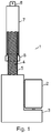
- FIG. 1 schematically shows an example of a linear actuator 1.
- the linear actuator 1 comprises a reversible electric motor 2, a transmission or reduction gear 3, typically with several stages, a spindle 4 having a thread 5, a spindle nut 6 engaging the thread 5 and a tube-shaped activation element 7.
- a mounting bracket 8 for mounting the linear actuator 1 to e.g. a carrying element is arranged.
- the spindle nut 6 is secured against rotation.
- the spindle nut is connected directly to e.g. a carrying element without the use of an activation element.
- the spindle nut 6 moves along the spindle 4, thus transforming the rotation to a linear movement of the spindle nut 6 and/or the activation element 7 between two end positions.
- the reversible electric motor 2 can drive the spindle 4 directly, so that the transmission 3 can be avoided.
- the reversible electric motor 2 is typically a reversible electric DC motor.
- a linear actuator is used in an actuator system controlled by a control box.
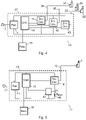
- An example of such an actuator system 11 is illustrated in Figure 2 .
- the linear actuator 1 Via a cable 12, the linear actuator 1 is connected to a control box 13 that comprises at least a power supply 14, a controller 15 and a driver circuit 16 for the linear actuator 1.
- the cable 12 between the driver circuit 16 and the linear actuator 1 may have a length of up to two meters or more.
- the driver circuit 16, and thus also the electric motor 2 of the actuator 1, is controlled by control signals from the controller 15.
- the controller 15 comprises a microcomputer.
- the control box 13 is normally placed on the equipment on which the linear actuator 1 is used.
- This equipment can represent any one of several different applications, such as trucks, agricultural machinery, industrial automation equipment, hospital and care beds, leisure beds and chairs, tables or other articles of furniture with adjustable height and several other similar applications.
- the power supply 14 is typically connected to a mains AC supply net with a power cable 17, but a battery may also be used, either alone or in combination with a supply connected to a mains net.
- the control box 13 is connected to a remote control 18 allowing the operation of the linear actuator 1 to be controlled by a person in the vicinity of the actuator.
- the connection between the remote control 18 and the control box 13 may be a wired connection as shown in Figure 2 , but a wireless communications system, such as a radio link or an infrared link, may also be used.
- the speed of the electric motors of the linear actuator 1 can be controlled by adjusting the DC voltage level supplied to the motor, or it can be controlled by using pulse width modulation (PWM), where the motor speed is instead controlled by adjusting the duty cycle of the pulse width modulation.
- PWM pulse width modulation
- the driver circuit 16 can be implemented in different ways.
- Figure 3 shows a typical example of the driver circuit 16 implemented as an H bridge driver circuit comprising four electronic switches 22, 23, 24 and 25.
- the driver circuit 16 allows each motor terminal of the motor 2 in the linear actuator 1 to be connected either to a positive supply voltage or to a ground terminal (or negative supply voltage), so that the motor 2 rotates in one direction when electronic switches 22 and 25 are closed, and in the other direction when electronic switches 23 and 24 are closed.
- the switches 22, 23, 24 and 25 may be any type of electronically controlled switches, such as field effect transistors (FETs), insulated-gate bipolar transistors (IGBTs) or bipolar transistors, and they are switched on and off by the controller 15.
- FETs field effect transistors
- IGBTs insulated-gate bipolar transistors
- bipolar transistors bipolar transistors
- a control box may also be configured to control an actuator system having a plurality of linear actuators.
- the linear actuators 31, 32 and 33 are connected to a control box 37 that comprises the power supply 14, the controller 15 (as in Figure 2 ) and a driver circuit for each linear actuator, i.e. driver circuits 41, 42 and 43.
- Each driver circuit, and thus also the electric motors of the actuators 31, 32 and 33, are controlled individually by control signals from the controller 15, which means that some or all of the actuator motors may be running simultaneously.
- the controller 15 can use the measured current value as a feedback signal in the control of the actuator 1.
- a maximum current limit can be defined for the actuator 1. If the measured current value exceeds this limit, it is an indication that the motor of the actuator is being overloaded, and the controller 15 can therefore be configured to switch off the motor if the limit is exceeded.
- the maximum current limit depends on the motor type, but a typical value could be in the range of 5 amperes.
- the controller 15 can adjust the level of the voltage supplied to the motor in dependence of the measured current value.
- a current measuring shunt resistor for measuring the current consumption of the linear actuators can also be utilized in the actuator system 30 of Figure 4 , where a plurality of actuators are connected to the control box. This is illustrated in Figure 6 , where a current measuring shunt resistor 46 having a low and well-defined resistance is inserted in series with the actuators 31, 32 and 33 and their driver circuits 41, 42 and 43. Also here, a voltage measuring device 47 connected across the shunt resistor 46 provides information about the current consumption to the controller 15.
- the current I sum through the current measuring shunt 46 is equal to the sum of the currents I 1 , I 2 and I 3 .
- the current measured by the shunt resistor 46 and the voltage measuring device 47 is the total current I sum consumed by the three driver circuits and their corresponding linear actuators.
- the controller 15 can be set to indicate (e.g. by giving an alarm or disconnecting the power to the actuators) when and if the measured current I sum exceeds 12 amperes.
- the actuators may well use less than their allowed maximum current, and in that case another actuator could exceed its own maximum current considerably before the total limit of 12 amperes is exceeded.
- actuators 31 and 32 only consume one ampere each, e.g. due to a low load
- actuator 33 could consume up to 10 amperes before the total limit of 12 amperes is exceeded. This would be more than three times its allowed maximum current, and the motor would probably be damaged although no overload indication has been provided by the current measurement.
- the controller 15 can be set to indicate when and if the measured current I sum exceeds nine amperes, which is the maximum current for the two actuators. However, if one of the actuators draws less than its allowed maximum current, the other actuator could actually draw more than its allowed maximum current before the limit of nine amperes is exceeded.
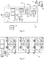
- FIG. 7 shows a more detailed diagram of a part of the control box 37 of the actuator system 30 of Figure 6 .
- Each driver circuit 41, 42 and 43 is implemented as an H bridge driver circuit comprising four electronic switches in the form of FETs, as it was shown in relation to Figure 3 .
- driver circuit 41 comprises FETs 54, 55, 56 and 57
- driver circuit 42 comprises FETs 58, 59, 60 and 61
- driver circuit 43 comprises FETs 62, 63, 64 and 65.
- the motors 51, 52 and 53 of the linear actuators 31, 32 and 33 are here shown as being a part of the driver circuits for reasons of simplicity, although as mentioned above, they may be arranged externally and connected to the driver circuits via cables. Similarly, for reasons of clarity the connections from the controller 15 to the FETs are not shown.
- the motors are driven by a DC voltage level.
- driver circuit 41 the voltage is supplied to the motor 51 via FETs 54 and 57 resulting in a motor current I 1 running in the motor.
- the voltage is supplied to the motor 52 in driver circuit 42 via FETs 58 and 61 resulting in a motor current I 2 running in the motor, and in driver circuit 43 the voltage is supplied to the motor 53 via FETs 64 and 63 resulting in a motor current I 3 running in the motor.
- the three motors are identical, they will rotate with approximately the same speed, since the same voltage level is supplied to the motors. However, since their load may differ from each other, also the currents I 1 , I 2 and I 3 may be different.
- the controller 15 can be configured to control the two other driver circuits and motors to draw no current from the power supply while a current measurement is performed by the shunt resistor 46 and the voltage measuring device 47. This can be done as illustrated in Figure 9 .
- FET 58 is switched off and instead FET 59 is switched on. Since FETs 58 and 60 are now both off, motor 52 is disconnected from the power supply and no current is drawn from the power supply by this driver circuit. Due to the inductive character of the motor 52, the current will continue to run in the motor, but this current will now circulate through FETs 59 and 61, so that the current I 2 drawn by driver circuit 42 and motor 52 will be zero.
- FET 64 is switched off and instead FET 65 is switched on, and the motor current will circulate through FETs 63 and 65, so that also the current I 3 drawn by driver circuit 43 and motor 53 will be zero.
- FETs 61 and 63 could be switched off and FETs 60 and 62 switched on, so that the motor currents of motors 52 and 53 would circulate through FETs 58 and 60 and FETs 62 and 64, respectively.
- the current I 2 drawn by the motor 52 and the driver circuit 42 can be measured in the same way by disconnecting the motors 51 and 53 from the power supply for a short period of time around t 2 . This is done by switching FETs 54 and 64 off and FETs 55 and 65 on, so that currents I 1 and I 3 will be zero and the total current I sum will equal the current I 2 drawn by the motor 52 and the driver circuit 42. Similarly, the current I 3 drawn by the motor 53 and the driver circuit 43 can be measured by disconnecting the motors 51 and 52 from the power supply for a short period of time around t 3 .
- the time between the current measurements i.e. the time between t 1 and t 2 and between t 2 and t 3
- the time between the current measurements can be selected according to the needs of the specific actuator system and the specific implementation of the controller 15.
- a time of 1 millisecond between the measurements could be an appropriate choice.
- the measurements can of course be repeated, so that for the system described above, current I 1 can again be measured 1 millisecond after the measurement of I 3 , and so on. This means that the current of each motor is measured with 3 milliseconds between each measurement.
- the measured values of I 1 , I 2 and I 3 that are provided to the controller 15 during the measurements described above can be compared to corresponding maximum current limits that have been predetermined for each of the motors 51, 52 and 53. If the measured current value for one of the motors (i.e. I 1 , I 2 or I 3 ) exceeds the corresponding limit, it is an indication that this motor is being overloaded, and the controller 15 can therefore be configured to switch off the motor if the limit is exceeded.
- motor 52 can be switched off if I 2 exceeds the corresponding limit. This can be done by switching FET 58 off and switching FET 59 on. In this way, an overload of this motor can be avoided.
- the described method can also be used when the motors of the linear actuators are driven by an AC voltage instead of a DC voltage as described above. However, in that case it will be expedient to synchronize the measurements with the frequency of the AC voltage, so that for a frequency of 50 Hz, the measurements can be performed with e.g. 20 milliseconds between the measurements to ensure that all measurements are comparable. It is also noted that for AC motors, the driver circuits will be different from the H bridge driver circuits described above.
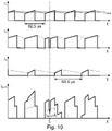
- Figure 10 illustrates how the current consumption of one of the three linear actuators in Figures 6, 7 and 9 can be measured by means of the single and common current measuring shunt resistor 46 in the situation where the motors are controlled with a pulse width modulated voltage. Similar to Figure 8 , Figure 10 shows the currents I 1 , I 2 and I 3 drawn from the power supply by the motors 51, 52 and 53 and the total current I sum . It is noted that at the time of the current measurement, the motors of the linear actuators may be controlled with different duty cycles and may even have different modulation frequencies.
- the modulation frequency of motors 51 and 52 is chosen to 16 kHz, corresponding to a period of 62.5 ⁇ s, while the modulation frequency of motor 53 is chosen to 12 kHz, corresponding to a period of 83.3 ⁇ s.
- the duty cycle of the three motors are shown as 50%, 62.5% and 25%, respectively.
- a motor draws an increasing current from the power supply.
- the current during the pulse can be considered as increasing linearly.
- the current continues to run in the motor due to its inductive character, and as it was shown in Figure 9 for e.g. driver circuit 42, this current circulates through FETs 59 and 61 and is not drawn from the power supply. This current can be considered as decreasing linearly, and it is indicated with a dashed line in Figure 10 .
- the average current I 1,avg in the motor is indicated in Figure 10 .
- the controller 15 can be configured to determine the current drawn by one of the motors by controlling the two other driver circuits and motors to draw no current from the power supply while a current measurement is performed by the shunt resistor 46 and the voltage measuring device 47. This can be done as it was described in relation to Figure 9 . This situation is shown at time t 1 in Figure 10 . Shortly before t 1 , motors 52 and 53 are controlled to be disconnected from the power supply as it was described above. In this case, one or both of the two other motors may be in a pulse pause around t 1 and thus already disconnected from the power supply. The controller 15 thus just ensures that they stay disconnected until the current measurement has been performed. This is illustrated for motor 53 in Figure 10 , where current I 3 is already zero around t 1 due to its pulse pause.
- the current I 1 of one of the three linear actuators has been measured by means of the one single and common current measuring shunt resistor 46. It is noted that the time t 1 , where the measurement of current I 1 is performed, need to be arranged during a PWM pulse for motor 51. If the measurement was performed during a pulse pause, the current would be zero.
- the measurement time t 1 for current I 1 can be arranged at the middle of a PWM pulse for motor 51, as it is illustrated in Figure 10 , because at this time the measured value of I 1 equals its average value I 1,avg , so that the measurement indicates the average current in the motor.
- the current I 2 drawn by the motor 52 and the driver circuit 42 can be measured in the same way by disconnecting the motors 51 and 53 from the power supply for a short period of time around t 2 , so that currents I 1 and I 3 will be zero and the total current I sum will equal the current I 2 drawn by the motor 52 and the driver circuit 42.
- the current I 3 drawn by the motor 53 and the driver circuit 43 can be measured by disconnecting the motors 51 and 52 from the power supply for a short period of time around a time t 3 .
- the time between the current measurements i.e. the time between t 1 and t 2 and between t 2 and t 3
- the time between the current measurements can be selected according to the needs of the specific actuator system and the specific implementation of the controller 15.
- a time of 1 millisecond between the measurements could be an appropriate choice.
- the measurements can of course be repeated, so that for the system described above, current I 1 can again be measured 1 millisecond after the measurement of I 3 , and so on. This means that the current of each motor is measured with 3 milliseconds between each measurement.
- the measured values of I 1 , I 2 and I 3 that are provided to the controller 15 during the measurements described above can be used as feedback signals in the control of the motors 51, 52 and 53.
- the duty cycle of the pulse width modulated voltage controlling each motor can be adjusted in dependence of the corresponding measured current value according to a control program stored in the controller 15.
- the measured values of I 1 , I 2 and I 3 can also be compared to corresponding maximum current limits that have been predetermined for each of the motors 51, 52 and 53. If the measured current value for one of the motors (i.e.
- I 1 , I 2 or I 3 exceeds the corresponding limit, it is an indication that this motor is being overloaded, and the controller 15 can therefore be configured to reduce the duty cycle or switch off the motor if the limit is exceeded.
- motor 52 can be switched off if I 2 exceeds the corresponding limit. In this way, an overload of this motor can be avoided.
- the controller 15 of the control box 37 is configured to control the motors of three linear actuators 31, 32 and 33 via three driver circuits 41, 42 and 43.
- these numbers are only used as examples. More generally, the described method makes it possible to measure the current consumption of individual motors of a plurality of motors supplied from the same power supply with the use of only one single current measuring shunt resistor and corresponding voltage measuring device. Thus, there could also be only two motors, or there could be four or more motors controlled by the controller.
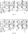
- Figures 11 and 12 show an example where four motors are controlled via two driver circuits.
- two motors 71 and 72 are controlled via a driver circuit 68 and two motors 73 and 74 are controlled via a driver circuit 69.
- Each driver circuit comprises six FETs arranged in three half bridges.
- the six FETs 75, 76, 77, 78, 79 and 80 are arranged to drive motors 71 and 72.
- two FETs can be saved compared to the driver circuits of Figure 7 , where eight FETs would be needed to drive two motors. Of course, this means that there are some restrictions on the direction of rotation of the motors. If e.g.
- motor 71 is driven through FETs 75 and 78, as shown in Figure 11 , FET 77 needs to be off to avoid a short circuit and thus motor 72 can only be driven through FETs 79 and 78. However, in many applications, this is fully acceptable, such as hospital beds or tables with adjustable height where both ends of the bed or the table will normally be either raised or lowered at the same time.
- Figure 11 illustrates the currents I 1 and I 2 through motors 71 and 72, respectively.
- driver circuit 69 the six FETs 81, 82, 83, 84, 85 and 86 are arranged to drive motors 73 and 74.
- Figure 11 also illustrates the currents I 3 and I 4 through motors 73 and 74 driven by FETs 83, 82 and 86.
- the controller 15 can, as in the examples above, be configured to control the other motors to draw no current from the power supply while a current measurement is performed by the shunt resistor 46 and the voltage measuring device 47. This can be done as illustrated in Figure 12 .
- FET 79 is switched off and instead FET 80 is switched on.
- Motor 72 is now disconnected from the power supply and no current is drawn from the power supply by this motor. Due to the inductive character of the motor 72, the current will continue to run in the motor, but this current will now circulate through FETs 78 and 80, so that the current I 2 drawn by motor 72 will be zero.
- FET 83 is switched off and instead FET 84 is switched on, so that the motor current in motor 73 will circulate through FETs 82 and 84 and the motor current in motor 74 will circulate through FETs 86 and 84.
- the currents I 3 and I 4 drawn by motors 73 and 74, respectively, will be zero.
- driver circuit 69 as an alternative FETs 82 and 86 could be switched off and FETs 81 and 85 switched on, so that the motor currents of motors 72 and 73 would circulate through FETs 81 and 83 and FETs 85 and 83, respectively.
- the controller 15 restores the situation of Figure 11 by switching FETs 79 and 83 on and FETs 80 and 84 off again. In this way, the current I 1 of one of the four linear actuators has been measured by means of the one single and common current measuring shunt resistor 46.
- the disconnection of the motors 72, 73 and 74 from the power supply for a short period of time around t 1 is of course a disturbance of these motors, but since this period of time may be as short as a few microseconds (depending of the implementation of the controller 15), this disturbance is fully acceptable.
- the electric motors are used in linear actuator systems, where reversible motors are needed.
- the motors can rotate in one direction, which allows the use of simpler driving circuits.
- An example of such a system 87 is illustrated in Figures 13 and 14 .
- the method of measuring the current in a selected one of a plurality of electric motors described above can also be used in such systems.
- the controller 15 is arranged to control the three electric motors 91, 92 and 93 via FETs 94, 95 and 96.
- the currents I 1 , I 2 and I 3 through the motors are shown for the situation where all three motors are running. Free-running diodes 97, 98 and 99 ensure that the motor currents can continue to circulate e.g. in pulse pauses of a pulse width modulated system.
- the current I sum through the shunt resistor 46 will be equal to the sum of the three currents I 1 , I 2 and I 3 .
- the controller 15 can, as in the examples above, be configured to control the other motors to draw no current from the power supply while a current measurement is performed by the shunt resistor 46 and the voltage measuring device 47. This can be done as illustrated in Figure 14 , where FETs 95 and 96 are switched off, so that motors 92 and 93 are disconnected from the power supply and no current is drawn from the power supply by these motors. Due to the inductive character of the motors 92 and 93, the current will continue to run in the motors, but this current will now circulate through the free-running diodes 98 and 99, so that the currents I 2 and I 3 drawn from the power supply will be zero.
- the voltage measuring device 47 which is connected across the shunt resistor 46 and provides information to the controller 15 about the current flowing through the shunt resistor 46, can be implemented in different ways.
- a traditional implementation is shown in Figure 15 , where the voltage across the shunt resistor 46 is sampled by a field effect transistor 101 and provided to a capacitor 102 through a resistor 103.
- the voltage on the capacitor 102 is then amplified by an amplifier 104 and provided to an input terminal of the microcomputer 105 of the controller 15.
- the received signal is then converted from an analog signal to a digital signal in an analog-to-digital converter (not shown) so that it can be processed by the microcomputer 105 and used in the control of the motors as described above.
- the resistance of the shunt resistor 46 is chosen appropriately, the voltage across it can be provided directly to the input terminal of the microcomputer 105 as shown in Figure 16 .
- This solution has the advantage that the signal path from the shunt resistor 46 to the input terminal of the microcomputer 105 has a higher bandwidth, which is relevant in order to reduce the short period of time around e.g. t 1 , where the other motors are disconnected from the power supply, as it was illustrated in e.g. Figure 10 . As mentioned above, this period of time may be as short as a few microseconds.
- the resistance of the shunt resistor 46 can be chosen to 40 m ⁇ .
- the bandwidth of the signal path from the shunt resistor 46 to the input terminal of the microcomputer 105 can be further improved. This is due to the fact that there will always be a certain small inductance in series with the shunt resistor 46, which can therefore be considered as an RL circuit composed of a resistor and an inductor. Above the 3dB bandwidth of the RL circuit the impedance will increase, which will thus also be the case for the voltage measured over the shunt resistor 46 for a given current value.
- the current I sum is measured by means of a current measuring shunt resistor 46 inserted in series with the electric motors.
- a current measuring shunt resistor 46 inserted in series with the electric motors.
- an ammeter can be used, provided it has an output that can provide a signal, which is representative of the measured current, to the controller 15.
- a current measuring transformer can be used.
- Hall Effect current sensor transducers can be used. These sensors can sense DC currents and they typically work up to frequencies around 150 kHz.
- a further sensor type that is well suited for the measurement of electric currents is magnetoresistive field current sensors. Some of these sensor types are available on the market as integrated circuits.
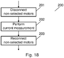
- FIG 18 shows a flow chart 200 illustrating a method of determining an electrical current flowing in a selected one of a plurality of electric motors connected to and supplied from a common power supply as described above.
- step 201 non-selected electric motors are controlled to be temporarily disconnected from the power supply 14 as it was described in relation to e.g. Figures 9 , 12 and 14 .
- step 202 a current measurement is performed by the current measuring device 46. Since the non-selected electric motors are now temporarily disconnected from the power supply 14, this current measurement is indicative of the electrical current flowing in the selected electric motor, as illustrated in e.g. Figures 9 and 10 .
- the non-selected electric motors are again controlled to be reconnected to the power supply 14 when the current measurement has been performed.
- a method of determining an electrical current flowing in a selected one of a plurality of electric motors connected to and supplied from a power supply wherein a current measuring device is arranged in a connection between the power supply and the plurality of electric motors.
- the method comprises the steps of controlling non-selected electric motors to be temporarily disconnected from the power supply; performing a current measurement by said current measuring device while the non-selected electric motors are temporarily disconnected from the power supply, said current measurement being indicative of the electrical current flowing in the selected electric motor; and controlling the non-selected electric motors to be reconnected to the power supply when the current measurement has been performed.
- the current measured may be a current flowing in the electric motor of a selected one of a plurality of linear actuators, wherein each linear actuator comprises a reversible electric DC motor; a spindle driven by said reversible DC motor; and a spindle nut mounted on the spindle and secured against rotation, said spindle nut being arranged to be moved between two end positions.
- the method comprises the step of driving each of said electric motors by switching at least one electronic switch arranged in series with that electric motor on and off.
- the method may comprise the step of temporarily disconnecting non-selected electric motors from the power supply by switching at least one of the at least one electronic switch in series with non-selected electric motors off.
- the method comprises the step of driving the electric motors with a pulse width modulated voltage having a variable duty cycle, which is an expedient way of controlling electric motors, especially where several motors are powered from the same power supply.
- the method may comprise the step of performing said current measurement in the middle of a pulse of the pulse width modulated voltage driving the selected electric motor. In the middle of the pulse, the current equals the average current of the motor.
- the method comprises the step of adjusting the duty cycle of the pulse width modulated voltage driving the selected electric motor in dependence of the measured current indicative of the electrical current flowing in the selected electric motor.
- the method comprises the step of switching off the selected electric motor if the measured current indicative of the electrical current flowing in the selected electric motor exceeds a predetermined maximum value.
- the invention also relates to a system comprising a power supply; a plurality of electric motors connected to and supplied from said power supply; a controller; and at least one driver circuit being configured to drive the electric motors under control of the controller.
- the system further comprises a current measuring device arranged in a connection between the power supply and the plurality of electric motors, and the controller is configured to measure an electrical current flowing in a selected one of the electric motors by controlling non-selected electric motors to be temporarily disconnected from the power supply; performing a current measurement by said current measuring device while the non-selected electric motors are temporarily disconnected from the power supply, said current measurement being indicative of the electrical current flowing in the selected electric motor; and controlling the non-selected electric motors to be reconnected to the power supply when the current measurement has been performed.
- the controller When the controller is configured to temporarily disconnect all electric motors except one from the power supply while a current measurement is performed by the common current measuring device arranged between the power supply and the electric motors, it is achieved that the measured total current equals the current drawn by the motor that is not disconnected. In this way, the current drawn by individual motors can be determined with the use of only one current measuring device, so that additional costs and increased space requirements in the controller for several current measuring devices can be avoided. With the knowledge of the current consumption of individual motors, it is now possible to switch off a motor if its individual maximum current is exceeded due to overload, or the individual motors can be controlled in dependence of their current consumption.
- the system may be an actuator system comprising a plurality of linear actuators, each linear actuator comprising a reversible electric DC motor; a spindle driven by said reversible DC motor; and a spindle nut mounted on the spindle and secured against rotation, said spindle nut being arranged to be moved between two end positions.
- the actuator system may further comprise a control box comprising at least the power supply, the controller and the at least one driver circuit; and a plurality of cables, each cable connecting one of the linear actuators to a corresponding driver circuit in the control box.
- the system may comprise one or more linear actuators in combination with one or more other electric motors connected to and supplied from the same power supply.
- the at least one driver circuit comprises a plurality of electronic switches, wherein each of said electric motors is arranged in series with at least one of said plurality of electronic switches; and the at least one driver circuit is configured to drive each electric motor by switching the at least one electronic switch in series with that electric motor on and off under control of the controller.
- the plurality of electronic switches may be field effect transistors.
- the controller may be configured to temporarily disconnect non-selected electric motors from the power supply by switching at least one of the at least one electronic switch in series with non-selected electric motors off.
- the controller is configured to drive the electric motors with a pulse width modulated voltage having a variable duty cycle, which is an expedient way of controlling electric motors, especially where several motors are powered from the same power supply.
- the controller may be configured to perform said current measurement in the middle of a pulse of the pulse width modulated voltage driving the selected electric motor. In the middle of the pulse, the current equals the average current of the motor.
- the controller is configured to adjust the duty cycle of the pulse width modulated voltage driving the selected electric motor in dependence of the measured current indicative of the electrical current flowing in the selected electric motor.
- the controller is configured to switch off the selected electric motor if the measured current indicative of the electrical current flowing in the selected electric motor exceeds a predetermined maximum value.
- the system may comprise a plurality of driver circuits, each driver circuit being configured to drive one of the electric motors under control of the controller, and each driver circuit being implemented as an H bridge driver circuit comprising four electronic switches.
- the system may comprise at least one driver circuit comprising six electronic switches arranged in three half bridges, said driver circuit being configured to drive two electric motors under control of the controller.
- said current measuring device may be a current measuring shunt resistor, and the controller may be configured to perform said current measurement by measuring a voltage over said current measuring shunt resistor. This is a simple and cost effective way of measuring the current.
- Also disclosed is a computer program comprising program code means for performing the steps of the method described above when said computer program is run on a computer, and a computer readable medium having stored thereon program code means for performing the method described above when said program code means is run on a computer.
Description
- The invention relates to a method of determining an electrical current flowing in a selected one of a plurality of electric motors connected to and supplied from a power supply and to a system comprising a power supply and a plurality of electric motors connected to and supplied from said power supply. The invention also relates to a computer program and a computer readable medium.
- Electric motors are used in many different applications. As examples, linear actuators, other types of actuators, cooling fans, disk drives, automatic door openers, lifts and traction motors and/or other motors in vehicles (including movable beds and medical carts) can be mentioned. Electric motors can be powered by direct current (DC) sources, such as batteries or rectifiers, or by alternating current (AC) sources, such as the power grid. Typically, the running speed of an electric motor is controlled by a motor controller. An example of a linear actuator with an electric motor is known from
WO 2008/080400 . DocumentEP3200340 discloses a power conversion device for controlling a plurality of electric motors comprising phase current detectors for detecting the respective phase currents output from the inverter. - For many types of electric motors (including DC motors and universal motors) and under normal use conditions, the running speed of the motor is proportional to the motor supply voltage, while the delivered mechanical torque or force is proportional to the current drawn from the supply. This means that if the mechanical load of the motor increases, a higher current is drawn from the supply. This higher current provides the additional torque to balance the increased load.
- If the motor is overloaded, e.g. because a too heavy load is placed on a hospital bed or a table with adjustable height driven by a linear actuator, or simply because the device driven by the motor is being blocked, the current drawn from the supply may increase to a level that is damaging for the motor. Such damage can be prevented by detecting or measuring the current drawn by the motor and interrupting the supply to the motor if the current exceeds a predetermined maximum value. Alternatively, the supply voltage to the motor can be adjusted by the motor controller in dependence of the measured current.
- The current drawn by the motor can be measured by a current measuring device arranged in the connection between the motor and the power supply. The current measuring device can be e.g. an ammeter, a current measuring shunt resistor, a current measuring transformer, a Hall Effect current sensor transducer or a magnetoresistive field current sensor.
- In many applications, a plurality of electric motors are connected to and supplied from a common power supply. Also in this situation, a current measuring device can be arranged in the connection between the power supply and the motors so that the current drawn by the motors can be supervised. However in this case, since all motors should be allowed to draw their maximum current simultaneously, the predetermined maximum value needs to be the sum of the individual maximum values, so that the supply voltage to one or more of the motors is interrupted only if the measured current exceeds the sum of the maximum values. However, since some of the motors at a given time may draw little or even no current, another one of the motors could actually draw a current considerably higher than its own predetermined maximum value without the total maximum current value being exceeded. This means that this solution is not sufficient for protecting the individual motors against overload.
- A solution could be to arrange a separate current measuring device in the connection to each motor so that their current consumption can be measured individually. However, the use of several current measuring devices means that an increased number of components is needed, which results in an additional cost as well as an increased space requirement in the controller. Further, a separate input terminal on the controller is required for each current measuring device, which is not always available.
- Therefore, it is an object of embodiments of the invention to provide a simple and cost effective method of determining an electrical current drawn by an individual one of a plurality of electric motors connected to and supplied from a common power supply without the need for the use of a separate current measuring device for each individual motor.
- According to embodiments of the invention, the object is achieved in a method of determining an electrical current flowing in a selected one of a plurality of electric motors connected to and supplied from a power supply, wherein a current measuring device is arranged in a connection between the power supply and the plurality of electric motors. The object is achieved when the method comprises the steps of controlling non-selected electric motors to be temporarily disconnected from the power supply; performing a current measurement by said current measuring device while the non-selected electric motors are temporarily disconnected from the power supply, said current measurement being indicative of the electrical current flowing in the selected electric motor; and controlling the non-selected electric motors to be reconnected to the power supply when the current measurement has been performed.
- By temporarily disconnecting all electric motors except one from the power supply while a current measurement is performed by the common current measuring device arranged between the power supply and the electric motors, it is achieved that the measured total current equals the current drawn by the motor that is not disconnected. In this way, the current drawn by individual motors can be determined with the use of only one current measuring device, so that additional costs and increased space requirements in the controller for several current measuring devices can be avoided. With the knowledge of the current consumption of individual motors, it is now possible to switch off a motor if its individual maximum current is exceeded due to overload, or the individual motors can be controlled in dependence of their current consumption. The current measured may be a current flowing in the electric motor of a selected one of a plurality of linear actuators, wherein each linear actuator comprises a reversible electric DC motor; a spindle driven by said reversible DC motor; and a spindle nut mounted on the spindle and secured against rotation, said spindle nut being arranged to be moved between two end positions.
- In some embodiments, the method comprises the step of driving each of said electric motors by switching at least one electronic switch arranged in series with that electric motor on and off.
- The method may comprise the step of temporarily disconnecting non-selected electric motors from the power supply by switching at least one of the at least one electronic switch in series with non-selected electric motors off. By using the electronic switches that are already arranged for driving the electric motors to temporarily disconnect non-selected electric motors from the power supply, there is no need for additional components for this purpose.
- In some embodiments, the method comprises the step of driving the electric motors with a pulse width modulated voltage having a variable duty cycle, which is an expedient way of controlling electric motors, especially where several motors are powered from the same power supply. In this case, the method may comprise the step of performing said current measurement in the middle of a pulse of the pulse width modulated voltage driving the selected electric motor. In the middle of the pulse, the current equals the average current of the motor. In some embodiments, the method comprises the step of adjusting the duty cycle of the pulse width modulated voltage driving the selected electric motor in dependence of the measured current indicative of the electrical current flowing in the selected electric motor.
- In some embodiments, the method comprises the step of switching off the selected electric motor if the measured current indicative of the electrical current flowing in the selected electric motor exceeds a predetermined maximum value.
- As mentioned, the invention also relates to a system comprising a power supply; a plurality of electric motors connected to and supplied from said power supply; a controller; and at least one driver circuit being configured to drive the electric motors under control of the controller. The system further comprises a current measuring device arranged in a connection between the power supply and the plurality of electric motors, and the controller is configured to measure an electrical current flowing in a selected one of the electric motors by controlling non-selected electric motors to be temporarily disconnected from the power supply; performing a current measurement by said current measuring device while the non-selected electric motors are temporarily disconnected from the power supply, said current measurement being indicative of the electrical current flowing in the selected electric motor; and controlling the non-selected electric motors to be reconnected to the power supply when the current measurement has been performed.
- When the controller is configured to temporarily disconnect all electric motors except one from the power supply while a current measurement is performed by the common current measuring device arranged between the power supply and the electric motors, it is achieved that the measured total current equals the current drawn by the motor that is not disconnected. In this way, the current drawn by individual motors can be determined with the use of only one current measuring device, so that additional costs and increased space requirements in the controller for several current measuring devices can be avoided. With the knowledge of the current consumption of individual motors, it is now possible to switch off a motor if its individual maximum current is exceeded due to overload, or the individual motors can be controlled in dependence of their current consumption.
- The system may be an actuator system comprising a plurality of linear actuators, each linear actuator comprising a reversible electric DC motor; a spindle driven by said reversible DC motor; and a spindle nut mounted on the spindle and secured against rotation, said spindle nut being arranged to be moved between two end positions. The actuator system may further comprise a control box comprising at least the power supply, the controller and the at least one driver circuit; and a plurality of cables, each cable connecting one of the linear actuators to a corresponding driver circuit in the control box. Alternatively, the system may comprise one or more linear actuators in combination with one or more other electric motors connected to and supplied from the same power supply.
- In some embodiments, the at least one driver circuit comprises a plurality of electronic switches, wherein each of said electric motors is arranged in series with at least one of said plurality of electronic switches; and the at least one driver circuit is configured to drive each electric motor by switching the at least one electronic switch in series with that electric motor on and off under control of the controller. The plurality of electronic switches may be field effect transistors.
- The controller may be configured to temporarily disconnect non-selected electric motors from the power supply by switching at least one of the at least one electronic switch in series with non-selected electric motors off. By using the electronic switches that are already arranged for driving the electric motors to temporarily disconnect non-selected electric motors from the power supply, there is no need for additional components for this purpose.
- In some embodiments, the controller is configured to drive the electric motors with a pulse width modulated voltage having a variable duty cycle, which is an expedient way of controlling electric motors, especially where several motors are powered from the same power supply. In this case, the controller may be configured to perform said current measurement in the middle of a pulse of the pulse width modulated voltage driving the selected electric motor. In the middle of the pulse, the current equals the average current of the motor. In some embodiments, the controller is configured to adjust the duty cycle of the pulse width modulated voltage driving the selected electric motor in dependence of the measured current indicative of the electrical current flowing in the selected electric motor.
- In some embodiments, the controller is configured to switch off the selected electric motor if the measured current indicative of the electrical current flowing in the selected electric motor exceeds a predetermined maximum value.
- The system may comprise a plurality of driver circuits, each driver circuit being configured to drive one of the electric motors under control of the controller, and each driver circuit being implemented as an H bridge driver circuit comprising four electronic switches.
- Alternatively, the system may comprise at least one driver circuit comprising six electronic switches arranged in three half bridges, said driver circuit being configured to drive two electric motors under control of the controller.
- In some embodiments, said current measuring device may be a current measuring shunt resistor, and the controller may be configured to perform said current measurement by measuring a voltage over said current measuring shunt resistor. This is a simple and cost effective way of measuring the current.
- The invention also relates to a computer program comprising program code means for performing the steps of the method described above when said computer program is run on a computer, and to a computer readable medium having stored thereon program code means for performing the method described above when said program code means is run on a computer.
- Embodiments of the invention will now be described more fully below with reference to the drawings, in which
-
Figure 1 schematically shows an example of a linear actuator, -
Figure 2 shows an example of an actuator system, where a linear actuator is controlled by a control box, -
Figure 3 shows an electric diagram of a linear actuator connected via a cable to a driver circuit, -
Figure 4 shows an example of an actuator system, where three linear actuators are controlled by a control box, -
Figure 5 shows a current measuring shunt resistor inserted in series with the actuator of the actuator system ofFigure 2 , -
Figure 6 shows a current measuring shunt resistor inserted in series with the three actuators of the actuator system ofFigure 4 , -
Figure 7 shows a more detailed diagram of a part of the control box of the actuator system ofFigure 6 with H bridge driver circuits and with indication of currents when all three motors are active, -
Figure 8 shows the waveforms of the currents in the three motors and the total current in the shunt resistor ofFigure 7 , when the motors are driven with a DC voltage and two motors are temporarily disconnected from the power supply, -
Figure 9 shows the diagram ofFigure 7 with indication of currents when two motors are temporarily disconnected from the power supply, -
Figure 10 shows the waveforms of the currents in the three motors and the total current in the shunt resistor ofFigure 7 , when the motors are driven with a pulse width modulated voltage and two motors are temporarily disconnected from the power supply, -
Figure 11 shows a detailed diagram of a part of a control box of an alternative actuator system where four motors are controlled via two driver circuits and with indication of currents when all four motors are active, -
Figure 12 shows the diagram ofFigure 11 with indication of currents when three motors are temporarily disconnected from the power supply, -
Figure 13 shows a detailed diagram of a motor system with three electric motors and with indication of currents when all three motors are active, -
Figure 14 shows the diagram ofFigure 13 with indication of currents when two motors are temporarily disconnected from the power supply, -
Figure 15 shows an example of an implementation of a voltage measuring device connected across a current measuring shunt resistor, -
Figure 16 shows an example where a current measuring shunt resistor is connected directly to a microcomputer in a controller, -
Figure 17 shows an example where a current measuring shunt resistor is connected to a microcomputer in a controller via an RC circuit, and -
Figure 18 shows a flow chart illustrating a method of determining an electrical current flowing in a selected one of a plurality of electric motors connected to and supplied from a common power supply. -
Figure 1 schematically shows an example of alinear actuator 1. Thelinear actuator 1 comprises a reversibleelectric motor 2, a transmission orreduction gear 3, typically with several stages, aspindle 4 having athread 5, aspindle nut 6 engaging thethread 5 and a tube-shapedactivation element 7. At the end of theactivation element 7, a mountingbracket 8 for mounting thelinear actuator 1 to e.g. a carrying element is arranged. Thespindle nut 6 is secured against rotation. In some linear actuators, the spindle nut is connected directly to e.g. a carrying element without the use of an activation element. When thespindle 4 is rotated by themotor 2, thespindle nut 6 moves along thespindle 4, thus transforming the rotation to a linear movement of thespindle nut 6 and/or theactivation element 7 between two end positions. It is noted that with some motor types, the reversibleelectric motor 2 can drive thespindle 4 directly, so that thetransmission 3 can be avoided. Although other types of electric motors may be used, the reversibleelectric motor 2 is typically a reversible electric DC motor. - Typically, a linear actuator is used in an actuator system controlled by a control box. An example of such an
actuator system 11 is illustrated inFigure 2 . Via acable 12, thelinear actuator 1 is connected to acontrol box 13 that comprises at least apower supply 14, acontroller 15 and adriver circuit 16 for thelinear actuator 1. Thecable 12 between thedriver circuit 16 and thelinear actuator 1 may have a length of up to two meters or more. Thedriver circuit 16, and thus also theelectric motor 2 of theactuator 1, is controlled by control signals from thecontroller 15. Typically, thecontroller 15 comprises a microcomputer. Thecontrol box 13 is normally placed on the equipment on which thelinear actuator 1 is used. This equipment can represent any one of several different applications, such as trucks, agricultural machinery, industrial automation equipment, hospital and care beds, leisure beds and chairs, tables or other articles of furniture with adjustable height and several other similar applications. Thepower supply 14 is typically connected to a mains AC supply net with apower cable 17, but a battery may also be used, either alone or in combination with a supply connected to a mains net. Finally, thecontrol box 13 is connected to aremote control 18 allowing the operation of thelinear actuator 1 to be controlled by a person in the vicinity of the actuator. The connection between theremote control 18 and thecontrol box 13 may be a wired connection as shown inFigure 2 , but a wireless communications system, such as a radio link or an infrared link, may also be used. - The speed of the electric motors of the
linear actuator 1 can be controlled by adjusting the DC voltage level supplied to the motor, or it can be controlled by using pulse width modulation (PWM), where the motor speed is instead controlled by adjusting the duty cycle of the pulse width modulation. - The
driver circuit 16 can be implemented in different ways.Figure 3 shows a typical example of thedriver circuit 16 implemented as an H bridge driver circuit comprising fourelectronic switches driver circuit 16 allows each motor terminal of themotor 2 in thelinear actuator 1 to be connected either to a positive supply voltage or to a ground terminal (or negative supply voltage), so that themotor 2 rotates in one direction whenelectronic switches electronic switches switches controller 15. InFigure 3 , the electronic switches are shown as FETs. - A control box may also be configured to control an actuator system having a plurality of linear actuators. An example of an
actuator system 30, where threelinear actuators Figure 4 . Viacables linear actuators control box 37 that comprises thepower supply 14, the controller 15 (as inFigure 2 ) and a driver circuit for each linear actuator, i.e.driver circuits actuators controller 15, which means that some or all of the actuator motors may be running simultaneously. - In many situations, it is relevant to know the current consumption of linear actuators, or at least to know if this current consumption exceeds a certain limit. As shown in
Figure 5 , knowledge of the current consumption of thelinear actuator 1 in theactuator system 11 ofFigure 2 can be obtained by inserting a currentmeasuring shunt resistor 46 having a low and well-defined resistance in series with theactuator 1 and itsdriver circuit 16. The voltage drop across theshunt 46 is proportional to the current I1 flowing through it and as its resistance is known, the voltage across theshunt 46 directly indicates the value of current I1. Thus, avoltage measuring device 47 connected across theshunt resistor 46 can provide information about the current consumption of thelinear actuator 1 to thecontroller 15. Thecontroller 15 can use the measured current value as a feedback signal in the control of theactuator 1. As an example, a maximum current limit can be defined for theactuator 1. If the measured current value exceeds this limit, it is an indication that the motor of the actuator is being overloaded, and thecontroller 15 can therefore be configured to switch off the motor if the limit is exceeded. The maximum current limit depends on the motor type, but a typical value could be in the range of 5 amperes. Alternatively, thecontroller 15 can adjust the level of the voltage supplied to the motor in dependence of the measured current value. - The use of a current measuring shunt resistor for measuring the current consumption of the linear actuators can also be utilized in the
actuator system 30 ofFigure 4 , where a plurality of actuators are connected to the control box. This is illustrated inFigure 6 , where a currentmeasuring shunt resistor 46 having a low and well-defined resistance is inserted in series with theactuators driver circuits voltage measuring device 47 connected across theshunt resistor 46 provides information about the current consumption to thecontroller 15. If the currents delivered by the power supply 19 to each of thedriver circuits linear actuators shunt 46 is equal to the sum of the currents I1, I2 and I3. Thus, the current measured by theshunt resistor 46 and thevoltage measuring device 47 is the total current Isum consumed by the three driver circuits and their corresponding linear actuators. - However, in some cases, knowledge about the total current consumption is not sufficient. If, as an example, it is assumed that the maximum currents for the
linear actuators controller 15 can be set to indicate (e.g. by giving an alarm or disconnecting the power to the actuators) when and if the measured current Isum exceeds 12 amperes. However, one or more of the actuators may well use less than their allowed maximum current, and in that case another actuator could exceed its own maximum current considerably before the total limit of 12 amperes is exceeded. Thus, ifactuators actuator 33 could consume up to 10 amperes before the total limit of 12 amperes is exceeded. This would be more than three times its allowed maximum current, and the motor would probably be damaged although no overload indication has been provided by the current measurement. - In a situation where only two actuators,
e.g. actuators actuator 14 is inactive, thecontroller 15 can be set to indicate when and if the measured current Isum exceeds nine amperes, which is the maximum current for the two actuators. However, if one of the actuators draws less than its allowed maximum current, the other actuator could actually draw more than its allowed maximum current before the limit of nine amperes is exceeded. - This problem could of course be solved by arranging a separate current measuring shunt resistor and corresponding voltage measuring device for each actuator so that their current consumption can be measured individually. However, this means that several additional components are needed and requires the use of additional inputs to the controller, which makes this solution less attractive.
- Below, a solution is described that makes it possible to measure the current consumption of the actuators individually with the use of only one single current measuring shunt resistor and corresponding voltage measuring device.
Figure 7 shows a more detailed diagram of a part of thecontrol box 37 of theactuator system 30 ofFigure 6 . Eachdriver circuit Figure 3 . Thus,driver circuit 41 comprisesFETs driver circuit 42 comprisesFETs driver circuit 43 comprisesFETs motors linear actuators controller 15 to the FETs are not shown. - In this example, the motors are driven by a DC voltage level. In
driver circuit 41, the voltage is supplied to themotor 51 viaFETs motor 52 indriver circuit 42 viaFETs driver circuit 43 the voltage is supplied to themotor 53 viaFETs Figure 8 , which shows the currents I1, I2, I3 and the total current Isum as a function of time. As it can be seen, the total current Isum equals I1 + I2 + I3, and thus as mentioned above, the current Isum measured by theshunt resistor 46 and thevoltage measuring device 47 is the total current drawn by all three driver circuits and the corresponding motors in the linear actuators. - In order to determine the current drawn by one of the motors, the
controller 15 can be configured to control the two other driver circuits and motors to draw no current from the power supply while a current measurement is performed by theshunt resistor 46 and thevoltage measuring device 47. This can be done as illustrated inFigure 9 . In thedriver circuit 42,FET 58 is switched off and insteadFET 59 is switched on. SinceFETs motor 52 is disconnected from the power supply and no current is drawn from the power supply by this driver circuit. Due to the inductive character of themotor 52, the current will continue to run in the motor, but this current will now circulate throughFETs driver circuit 42 andmotor 52 will be zero. Similarly, indriver circuit 43FET 64 is switched off and insteadFET 65 is switched on, and the motor current will circulate throughFETs driver circuit 43 andmotor 53 will be zero. - It is noted that alternatively,
FETs FETs motors FETs FETs - This situation is shown at time t1 in
Figure 8 . Shortly before t1,motors Figure 9 and described above, and since currents I2 and I3 are now zero, the total current Isum will equal the current I1 drawn by themotor 51 and thedriver circuit 41. At time t1, a current measurement is then performed by theshunt resistor 46 and thevoltage measuring device 47, and the measured value of Isum = I1 is provided to thecontroller 15. When the measurement has been performed, thecontroller 15 restores the situation ofFigure 7 by switchingFETs FETs measuring shunt resistor 46. - The disconnection of the
motors - At time t2, the current I2 drawn by the
motor 52 and thedriver circuit 42 can be measured in the same way by disconnecting themotors FETs FETs motor 52 and thedriver circuit 42. Similarly, the current I3 drawn by themotor 53 and thedriver circuit 43 can be measured by disconnecting themotors - The time between the current measurements, i.e. the time between t1 and t2 and between t2 and t3, can be selected according to the needs of the specific actuator system and the specific implementation of the
controller 15. For a typical actuator system, a time of 1 millisecond between the measurements could be an appropriate choice. The measurements can of course be repeated, so that for the system described above, current I1 can again be measured 1 millisecond after the measurement of I3, and so on. This means that the current of each motor is measured with 3 milliseconds between each measurement. - In the
controller 15, the measured values of I1, I2 and I3 that are provided to thecontroller 15 during the measurements described above can be compared to corresponding maximum current limits that have been predetermined for each of themotors controller 15 can therefore be configured to switch off the motor if the limit is exceeded. Thus, as an example,motor 52 can be switched off if I2 exceeds the corresponding limit. This can be done by switchingFET 58 off and switchingFET 59 on. In this way, an overload of this motor can be avoided. - The described method can also be used when the motors of the linear actuators are driven by an AC voltage instead of a DC voltage as described above. However, in that case it will be expedient to synchronize the measurements with the frequency of the AC voltage, so that for a frequency of 50 Hz, the measurements can be performed with e.g. 20 milliseconds between the measurements to ensure that all measurements are comparable. It is also noted that for AC motors, the driver circuits will be different from the H bridge driver circuits described above.
-
Figure 10 illustrates how the current consumption of one of the three linear actuators inFigures 6, 7 and9 can be measured by means of the single and common currentmeasuring shunt resistor 46 in the situation where the motors are controlled with a pulse width modulated voltage. Similar toFigure 8 ,Figure 10 shows the currents I1, I2 and I3 drawn from the power supply by themotors Figure 10 , the modulation frequency ofmotors motor 53 is chosen to 12 kHz, corresponding to a period of 83.3 µs. The duty cycle of the three motors are shown as 50%, 62.5% and 25%, respectively. During each pulse, a motor draws an increasing current from the power supply. In this context, the current during the pulse can be considered as increasing linearly. During the pauses between the pulses, the current continues to run in the motor due to its inductive character, and as it was shown inFigure 9 fore.g. driver circuit 42, this current circulates throughFETs Figure 10 . Formotor 51, the average current I1,avg in the motor is indicated inFigure 10 . - Also here, the
controller 15 can be configured to determine the current drawn by one of the motors by controlling the two other driver circuits and motors to draw no current from the power supply while a current measurement is performed by theshunt resistor 46 and thevoltage measuring device 47. This can be done as it was described in relation toFigure 9 . This situation is shown at time t1 inFigure 10 . Shortly before t1,motors controller 15 thus just ensures that they stay disconnected until the current measurement has been performed. This is illustrated formotor 53 inFigure 10 , where current I3 is already zero around t1 due to its pulse pause. - Since currents I2 and I3 are now zero, the total current Isum will equal the current I1 drawn by the
motor 51 and thedriver circuit 41. At time t1, a current measurement is then performed by theshunt resistor 46 and thevoltage measuring device 47, and the measured value of Isum = I1 is provided to thecontroller 15. When the measurement has been performed, thecontroller 15 restores the situation by allowingmotors Figure 10 , the pulse formotor 52 that was interrupted is now continued at a slightly lower level, while the pulse pause formotor 53 is continued until the start of the next pulse. In this way, the current I1 of one of the three linear actuators has been measured by means of the one single and common currentmeasuring shunt resistor 46. It is noted that the time t1, where the measurement of current I1 is performed, need to be arranged during a PWM pulse formotor 51. If the measurement was performed during a pulse pause, the current would be zero. - Expediently, the measurement time t1 for current I1 can be arranged at the middle of a PWM pulse for
motor 51, as it is illustrated inFigure 10 , because at this time the measured value of I1 equals its average value I1,avg, so that the measurement indicates the average current in the motor. - The disconnection of the
motors - At a time t2, which is not shown in
Figure 10 , the current I2 drawn by themotor 52 and thedriver circuit 42 can be measured in the same way by disconnecting themotors motor 52 and thedriver circuit 42. Similarly, the current I3 drawn by themotor 53 and thedriver circuit 43 can be measured by disconnecting themotors - Also in a pulse modulated system, the time between the current measurements, i.e. the time between t1 and t2 and between t2 and t3, can be selected according to the needs of the specific actuator system and the specific implementation of the
controller 15. For a typical actuator system, a time of 1 millisecond between the measurements could be an appropriate choice. The measurements can of course be repeated, so that for the system described above, current I1 can again be measured 1 millisecond after the measurement of I3, and so on. This means that the current of each motor is measured with 3 milliseconds between each measurement. - In the
controller 15, the measured values of I1, I2 and I3 that are provided to thecontroller 15 during the measurements described above can be used as feedback signals in the control of themotors controller 15. The measured values of I1, I2 and I3 can also be compared to corresponding maximum current limits that have been predetermined for each of themotors controller 15 can therefore be configured to reduce the duty cycle or switch off the motor if the limit is exceeded. Thus, as an example,motor 52 can be switched off if I2 exceeds the corresponding limit. In this way, an overload of this motor can be avoided. - In the examples described above, the
controller 15 of thecontrol box 37 is configured to control the motors of threelinear actuators driver circuits Figures 11 and 12 show an example where four motors are controlled via two driver circuits. - In
Figure 11 , twomotors driver circuit 68 and twomotors driver circuit 69. Each driver circuit comprises six FETs arranged in three half bridges. Thus, indriver circuit 68, the sixFETs motors Figure 7 , where eight FETs would be needed to drive two motors. Of course, this means that there are some restrictions on the direction of rotation of the motors. Ife.g. motor 71 is driven throughFETs Figure 11 ,FET 77 needs to be off to avoid a short circuit and thus motor 72 can only be driven throughFETs Figure 11 illustrates the currents I1 and I2 throughmotors driver circuit 69, the sixFETs motors Figure 11 also illustrates the currents I3 and I4 throughmotors FETs - In order to determine the current drawn by one of the motors, the
controller 15 can, as in the examples above, be configured to control the other motors to draw no current from the power supply while a current measurement is performed by theshunt resistor 46 and thevoltage measuring device 47. This can be done as illustrated inFigure 12 . In thedriver circuit 68,FET 79 is switched off and insteadFET 80 is switched on.Motor 72 is now disconnected from the power supply and no current is drawn from the power supply by this motor. Due to the inductive character of themotor 72, the current will continue to run in the motor, but this current will now circulate throughFETs motor 72 will be zero. Similarly, indriver circuit 69FET 83 is switched off and insteadFET 84 is switched on, so that the motor current inmotor 73 will circulate throughFETs motor 74 will circulate throughFETs motors - It is noted that in
driver circuit 69, as analternative FETs FETs motors FETs FETs - This situation corresponds to the situation that was shown at time t1 in
Figures 8 and10 , except that there is now also a fourth current I4. Shortly before t1,motors Figure 12 and described above, and since currents I2, I3 and I4 are now zero, the total current Isum will equal the current I1 drawn by themotor 71 in thedriver circuit 68. At time t1, a current measurement is then performed by theshunt resistor 46 and thevoltage measuring device 47, and the measured value of Isum = I1 is provided to thecontroller 15. When the measurement has been performed, thecontroller 15 restores the situation ofFigure 11 by switchingFETs FETs measuring shunt resistor 46. - Also here, the disconnection of the
motors - In the examples described above, the electric motors are used in linear actuator systems, where reversible motors are needed. However, in several other systems using electric motors, such as cooling fan systems, it is sufficient that the motors can rotate in one direction, which allows the use of simpler driving circuits. An example of such a
system 87 is illustrated inFigures 13 and 14 . The method of measuring the current in a selected one of a plurality of electric motors described above can also be used in such systems. - In
Figure 13 , thecontroller 15 is arranged to control the threeelectric motors FETs diodes Figure 13 the current Isum through theshunt resistor 46 will be equal to the sum of the three currents I1, I2 and I3. - In order to determine the current drawn by one of the motors in this system, the
controller 15 can, as in the examples above, be configured to control the other motors to draw no current from the power supply while a current measurement is performed by theshunt resistor 46 and thevoltage measuring device 47. This can be done as illustrated inFigure 14 , whereFETs motors motors diodes - This situation corresponds to the situation that was shown at time t1 in
Figures 8 and10 . Shortly before t1,motors Figure 14 and described above, and since currents I2 and I3 are now zero, the total current Isum will equal the current I1 drawn by the motor 91. At time t1, a current measurement is then performed by theshunt resistor 46 and thevoltage measuring device 47, and the measured value of Isum = I1 is provided to thecontroller 15. When the measurement has been performed, thecontroller 15 restores the situation ofFigure 13 by switchingFETs measuring shunt resistor 46. - The
voltage measuring device 47, which is connected across theshunt resistor 46 and provides information to thecontroller 15 about the current flowing through theshunt resistor 46, can be implemented in different ways. A traditional implementation is shown inFigure 15 , where the voltage across theshunt resistor 46 is sampled by afield effect transistor 101 and provided to acapacitor 102 through aresistor 103. The voltage on thecapacitor 102 is then amplified by anamplifier 104 and provided to an input terminal of themicrocomputer 105 of thecontroller 15. In themicrocomputer 105, the received signal is then converted from an analog signal to a digital signal in an analog-to-digital converter (not shown) so that it can be processed by themicrocomputer 105 and used in the control of the motors as described above. - However, if the resistance of the
shunt resistor 46 is chosen appropriately, the voltage across it can be provided directly to the input terminal of themicrocomputer 105 as shown inFigure 16 . This solution has the advantage that the signal path from theshunt resistor 46 to the input terminal of themicrocomputer 105 has a higher bandwidth, which is relevant in order to reduce the short period of time around e.g. t1, where the other motors are disconnected from the power supply, as it was illustrated in e.g.Figure 10 . As mentioned above, this period of time may be as short as a few microseconds. As an example, the resistance of theshunt resistor 46 can be chosen to 40 mΩ. - The analog-to-digital converter at the input terminal of the
microcomputer 105 can typically have an overall voltage measurement range (full scale) of 3.3 Volts corresponding to a maximum current in theshunt resistor 46 of 3.3 V / 40 mΩ = 82.5 A, which will be considered as sufficient in this situation. If the analog-to-digital converter has a resolution of 10 bits corresponding to 1024 levels, the voltage resolution will be 3.2 mV corresponding to 80 mA in theshunt resistor 46, and if the analog-to-digital converter has a resolution of 12 bits corresponding to 4096 levels, the voltage resolution will be 0.8 mV corresponding to 20 mA in theshunt resistor 46. This resolution is also considered as being sufficient for the described application. - The bandwidth of the signal path from the
shunt resistor 46 to the input terminal of themicrocomputer 105 can be further improved. This is due to the fact that there will always be a certain small inductance in series with theshunt resistor 46, which can therefore be considered as an RL circuit composed of a resistor and an inductor. Above the 3dB bandwidth of the RL circuit the impedance will increase, which will thus also be the case for the voltage measured over theshunt resistor 46 for a given current value. It is noted that the 3dB bandwidth is determined by the time constant τ of the RL circuit (f3dB = 1 / 2πτ), which is defined as τ = L / Rshunt, where L is the small inductance in series with theshunt resistor 46. - This can be compensated by adding an RC circuit comprising a
capacitor 106 and aresistor 107 as shown inFigure 17 . The time constant τ of the RC circuit is defined as τ = R C, where R is the resistance ofresistor 107 and C is the capacitance ofcapacitor 106. If the RC circuit is designed to have the same time constant τ as the RL circuit of theshunt resistor 46, i.e. R C = L / Rshunt, the effect of the inductance in series with theshunt resistor 46 will be compensated, and the bandwidth will be considerably increased. - As an example, the small inductance in series with a shunt resistor of 40 mΩ can be estimated to approximately 40 nH resulting in a time constant τ = 1 µs for the RL circuit. A corresponding time constant τ for the RC circuit can be achieved with e.g. R = 100 Ω and C = 10 nF or R = 1 kΩ and C = 1 nF.
- In the examples described above, the current Isum is measured by means of a current
measuring shunt resistor 46 inserted in series with the electric motors. However, it is noted that other techniques of measuring the current can be used as well. A few such techniques are mentioned in the following. As an example, an ammeter can be used, provided it has an output that can provide a signal, which is representative of the measured current, to thecontroller 15. In some situations, depending on the character of the current to be measured, a current measuring transformer can be used. Also, Hall Effect current sensor transducers can be used. These sensors can sense DC currents and they typically work up to frequencies around 150 kHz. A further sensor type that is well suited for the measurement of electric currents is magnetoresistive field current sensors. Some of these sensor types are available on the market as integrated circuits. -
Figure 18 shows aflow chart 200 illustrating a method of determining an electrical current flowing in a selected one of a plurality of electric motors connected to and supplied from a common power supply as described above. Instep 201, non-selected electric motors are controlled to be temporarily disconnected from thepower supply 14 as it was described in relation to e.g.Figures 9 ,12 and14 . Instep 202, a current measurement is performed by thecurrent measuring device 46. Since the non-selected electric motors are now temporarily disconnected from thepower supply 14, this current measurement is indicative of the electrical current flowing in the selected electric motor, as illustrated in e.g.Figures 9 and10 . Finally, instep 203, the non-selected electric motors are again controlled to be reconnected to thepower supply 14 when the current measurement has been performed. - In other words, there is disclosed a method of determining an electrical current flowing in a selected one of a plurality of electric motors connected to and supplied from a power supply, wherein a current measuring device is arranged in a connection between the power supply and the plurality of electric motors. The method comprises the steps of controlling non-selected electric motors to be temporarily disconnected from the power supply; performing a current measurement by said current measuring device while the non-selected electric motors are temporarily disconnected from the power supply, said current measurement being indicative of the electrical current flowing in the selected electric motor; and controlling the non-selected electric motors to be reconnected to the power supply when the current measurement has been performed.
- By temporarily disconnecting all electric motors except one from the power supply while a current measurement is performed by the common current measuring device arranged between the power supply and the electric motors, it is achieved that the measured total current equals the current drawn by the motor that is not disconnected. In this way, the current drawn by individual motors can be determined with the use of only one current measuring device, so that additional costs and increased space requirements in the controller for several current measuring devices can be avoided. With the knowledge of the current consumption of individual motors, it is now possible to switch off a motor if its individual maximum current is exceeded due to overload, or the individual motors can be controlled in dependence of their current consumption.
- The current measured may be a current flowing in the electric motor of a selected one of a plurality of linear actuators, wherein each linear actuator comprises a reversible electric DC motor; a spindle driven by said reversible DC motor; and a spindle nut mounted on the spindle and secured against rotation, said spindle nut being arranged to be moved between two end positions.
- In some embodiments, the method comprises the step of driving each of said electric motors by switching at least one electronic switch arranged in series with that electric motor on and off.
- The method may comprise the step of temporarily disconnecting non-selected electric motors from the power supply by switching at least one of the at least one electronic switch in series with non-selected electric motors off. By using the electronic switches that are already arranged for driving the electric motors to temporarily disconnect non-selected electric motors from the power supply, there is no need for additional components for this purpose.
- In some embodiments, the method comprises the step of driving the electric motors with a pulse width modulated voltage having a variable duty cycle, which is an expedient way of controlling electric motors, especially where several motors are powered from the same power supply. In this case, the method may comprise the step of performing said current measurement in the middle of a pulse of the pulse width modulated voltage driving the selected electric motor. In the middle of the pulse, the current equals the average current of the motor. In some embodiments, the method comprises the step of adjusting the duty cycle of the pulse width modulated voltage driving the selected electric motor in dependence of the measured current indicative of the electrical current flowing in the selected electric motor.
- In some embodiments, the method comprises the step of switching off the selected electric motor if the measured current indicative of the electrical current flowing in the selected electric motor exceeds a predetermined maximum value.
- The invention also relates to a system comprising a power supply; a plurality of electric motors connected to and supplied from said power supply; a controller; and at least one driver circuit being configured to drive the electric motors under control of the controller. The system further comprises a current measuring device arranged in a connection between the power supply and the plurality of electric motors, and the controller is configured to measure an electrical current flowing in a selected one of the electric motors by controlling non-selected electric motors to be temporarily disconnected from the power supply; performing a current measurement by said current measuring device while the non-selected electric motors are temporarily disconnected from the power supply, said current measurement being indicative of the electrical current flowing in the selected electric motor; and controlling the non-selected electric motors to be reconnected to the power supply when the current measurement has been performed.
- When the controller is configured to temporarily disconnect all electric motors except one from the power supply while a current measurement is performed by the common current measuring device arranged between the power supply and the electric motors, it is achieved that the measured total current equals the current drawn by the motor that is not disconnected. In this way, the current drawn by individual motors can be determined with the use of only one current measuring device, so that additional costs and increased space requirements in the controller for several current measuring devices can be avoided. With the knowledge of the current consumption of individual motors, it is now possible to switch off a motor if its individual maximum current is exceeded due to overload, or the individual motors can be controlled in dependence of their current consumption.
- The system may be an actuator system comprising a plurality of linear actuators, each linear actuator comprising a reversible electric DC motor; a spindle driven by said reversible DC motor; and a spindle nut mounted on the spindle and secured against rotation, said spindle nut being arranged to be moved between two end positions. The actuator system may further comprise a control box comprising at least the power supply, the controller and the at least one driver circuit; and a plurality of cables, each cable connecting one of the linear actuators to a corresponding driver circuit in the control box. Alternatively, the system may comprise one or more linear actuators in combination with one or more other electric motors connected to and supplied from the same power supply.
- In some embodiments, the at least one driver circuit comprises a plurality of electronic switches, wherein each of said electric motors is arranged in series with at least one of said plurality of electronic switches; and the at least one driver circuit is configured to drive each electric motor by switching the at least one electronic switch in series with that electric motor on and off under control of the controller. The plurality of electronic switches may be field effect transistors.
- The controller may be configured to temporarily disconnect non-selected electric motors from the power supply by switching at least one of the at least one electronic switch in series with non-selected electric motors off. By using the electronic switches that are already arranged for driving the electric motors to temporarily disconnect non-selected electric motors from the power supply, there is no need for additional components for this purpose.
- In some embodiments, the controller is configured to drive the electric motors with a pulse width modulated voltage having a variable duty cycle, which is an expedient way of controlling electric motors, especially where several motors are powered from the same power supply. In this case, the controller may be configured to perform said current measurement in the middle of a pulse of the pulse width modulated voltage driving the selected electric motor. In the middle of the pulse, the current equals the average current of the motor. In some embodiments, the controller is configured to adjust the duty cycle of the pulse width modulated voltage driving the selected electric motor in dependence of the measured current indicative of the electrical current flowing in the selected electric motor.
- In some embodiments, the controller is configured to switch off the selected electric motor if the measured current indicative of the electrical current flowing in the selected electric motor exceeds a predetermined maximum value.
- The system may comprise a plurality of driver circuits, each driver circuit being configured to drive one of the electric motors under control of the controller, and each driver circuit being implemented as an H bridge driver circuit comprising four electronic switches.
- Alternatively, the system may comprise at least one driver circuit comprising six electronic switches arranged in three half bridges, said driver circuit being configured to drive two electric motors under control of the controller.
- In some embodiments, said current measuring device may be a current measuring shunt resistor, and the controller may be configured to perform said current measurement by measuring a voltage over said current measuring shunt resistor. This is a simple and cost effective way of measuring the current.
- Also disclosed is a computer program comprising program code means for performing the steps of the method described above when said computer program is run on a computer, and a computer readable medium having stored thereon program code means for performing the method described above when said program code means is run on a computer.
- Although various embodiments of the present invention have been described and shown, the invention is not restricted thereto, but may also be embodied in other ways within the scope of the subject-matter defined in the following claims.
Claims (16)
- A method of determining an electrical current flowing in a selected one of a plurality of electric motors (51, 52, 53; 71, 72, 73, 74; 91, 92, 93) connected to and supplied from a power supply (14), wherein a current measuring device (46) is arranged in a connection between the power supply (14) and the plurality of electric motors (51, 52, 53; 71, 72, 73, 74; 91, 92, 93),
characterized in that the method comprises the steps of:• controlling non-selected electric motors to be temporarily disconnected from the power supply (14);• performing a current measurement by said current measuring device (46) while the non-selected electric motors are temporarily disconnected from the power supply (14), said current measurement being indicative of the electrical current flowing in the selected electric motor; and• controlling the non-selected electric motors to be reconnected to the power supply (14) when the current measurement has been performed. - A system (30; 87) comprising:• a power supply (14);• a plurality of electric motors (51, 52, 53; 71, 72, 73, 74; 91, 92, 93) connected to and supplied from said power supply (14);• a controller (15); and• at least one driver circuit (41, 42, 43; 68, 69; 94, 95, 96) being configured to drive the electric motors (51, 52, 53; 71, 72, 73, 74; 91, 92, 93) under control of the controller (15),characterized in that the system further comprises a current measuring device (46) arranged in a connection between the power supply (14) and the plurality of electric motors (51, 52, 53; 71, 72, 73, 74; 91, 92, 93), and that
the controller (15) is configured to measure an electrical current flowing in a selected one of the electric motors (51, 52, 53; 71, 72, 73, 74; 91, 92, 93) by:• controlling non-selected electric motors to be temporarily disconnected from the power supply (14);• performing a current measurement by said current measuring device (46) while the non-selected electric motors are temporarily disconnected from the power supply (14), said current measurement being indicative of the electrical current flowing in the selected electric motor; and• controlling the non-selected electric motors to be reconnected to the power supply (14) when the current measurement has been performed. - A system according to claim 2, characterized in that the system is an actuator system (30) comprising a plurality of linear actuators (31, 32, 33), each linear actuator comprising:• a reversible electric DC motor (2);• a spindle (4) driven by said reversible DC motor (2); and• a spindle nut (6) mounted on the spindle (4) and secured against rotation, said spindle nut (6) being arranged to be moved between two end positions.
- A system according to claim 3, characterized in that the actuator system (30) further comprises:• a control box (37; 67) comprising at least the power supply (14), the controller (15) and the at least one driver circuit (41, 42, 43; 68, 69); and• a plurality of cables (34, 35, 36), each cable connecting one of the linear actuators (31, 32, 33) to a corresponding driver circuit in the control box (37; 67).
- A system according to any one of claims 2 to 4, characterized in that the at least one driver circuit (41, 42, 43; 68, 69; 94, 95, 96) comprises a plurality of electronic switches, wherein• each of said electric motors (51, 52, 53; 71, 72, 73, 74; 91, 92, 93) is arranged in series with at least one of said plurality of electronic switches;• and the at least one driver circuit (41, 42, 43; 68, 69; 94, 95, 96) is configured to drive each electric motor (51, 52, 53; 71, 72, 73, 74; 91, 92, 93) by switching the at least one electronic switch in series with that electric motor on and off under control of the controller (15).
- A system according to claim 5, characterized in that said plurality of electronic switches are field effect transistors.
- A system according to claim 5 or 6, characterized in that the controller (15) is configured to temporarily disconnect non-selected electric motors from the power supply (14) by switching at least one of the at least one electronic switch in series with non-selected electric motors off.
- A system according to any one of claims 2 to 7, characterized in that the controller (15) is configured to drive the electric motors (51, 52, 53; 71, 72, 73, 74; 91, 92, 93) with a pulse width modulated voltage having a variable duty cycle.
- A system according to claim 8, characterized in that the controller (15) is configured to perform said current measurement in the middle of a pulse of the pulse width modulated voltage driving the selected electric motor.
- A system according to claim 8 or 9, characterized in that the controller (15) is configured to adjust the duty cycle of the pulse width modulated voltage driving the selected electric motor in dependence of the measured current indicative of the electrical current flowing in the selected electric motor.
- A system according to any one of claims 2 to 10, characterized in that the controller (15) is configured to switch off the selected electric motor if the measured current indicative of the electrical current flowing in the selected electric motor exceeds a predetermined maximum value.
- A system according to any one of claims 2 to 11, characterized in that the system comprises a plurality of driver circuits (41, 42, 43), each driver circuit being configured to drive one of the electric motors (51, 52, 53) under control of the controller(15), and each driver circuit being implemented as an H bridge driver circuit comprising four electronic switches.
- A system according to any one of claims 2 to 11, characterized in that the system comprises at least one driver circuit (68; 69) comprising six electronic switches arranged in three half bridges, said driver circuit being configured to drive two electric motors (71, 72; 73, 74) under control of the controller (15).
- A system according to any one of claims 2 to 13, characterized in that said current measuring device is a current measuring shunt resistor (46), and that the controller (15) is configured to perform said current measurement by measuring a voltage over said current measuring shunt resistor (46).
- A computer program comprising program code means for performing the steps of claim 1 when said computer program is run on a computer.
- A computer readable medium having stored thereon program code means for performing the method of claim 1 when said program code means is run on a computer.
Applications Claiming Priority (2)
| Application Number | Priority Date | Filing Date | Title |
|---|---|---|---|
| DKPA201700657 | 2017-11-20 | ||
| PCT/DK2018/000178 WO2019096359A1 (en) | 2017-11-20 | 2018-11-20 | Determining an electrical current flowing in one of a plurality of electric motors |
Publications (2)
| Publication Number | Publication Date |
|---|---|
| EP3714541A1 EP3714541A1 (en) | 2020-09-30 |
| EP3714541B1 true EP3714541B1 (en) | 2022-07-27 |
Family
ID=64664838
Family Applications (1)
| Application Number | Title | Priority Date | Filing Date |
|---|---|---|---|
| EP18819257.9A Active EP3714541B1 (en) | 2017-11-20 | 2018-11-20 | Determining an electrical current flowing in one of a plurality of electric motors |
Country Status (6)
| Country | Link |
|---|---|
| US (1) | US20200366224A1 (en) |
| EP (1) | EP3714541B1 (en) |
| JP (1) | JP7237963B2 (en) |
| CN (1) | CN111373651A (en) |
| DK (1) | DK3714541T3 (en) |
| WO (1) | WO2019096359A1 (en) |
Families Citing this family (2)
| Publication number | Priority date | Publication date | Assignee | Title |
|---|---|---|---|---|
| JP7348032B2 (en) | 2019-11-05 | 2023-09-20 | ローム株式会社 | Current measurement circuit, current measurement method |
| CN115306248B (en) * | 2022-08-18 | 2024-01-05 | 宁波欧尼克科技有限公司 | Automatic reset flat-open door machine and control circuit thereof |
Family Cites Families (28)
| Publication number | Priority date | Publication date | Assignee | Title |
|---|---|---|---|---|
| JPH09184860A (en) * | 1995-08-16 | 1997-07-15 | Texas Instr Inc <Ti> | Apparatus for measuring average motor current and method therefor |
| US6545439B2 (en) * | 1998-10-27 | 2003-04-08 | Daimlerchrysler Ag | Method and circuit arrangement for detecting motion, direction and position of a part driven by an electric motor |
| US6841953B2 (en) * | 2000-07-05 | 2005-01-11 | Linak A/S | Control for two or more dc motors, in particular actuators for adjustment of furniture |
| US7038421B2 (en) * | 2003-06-17 | 2006-05-02 | International Business Machines Corporation | Method and system for multiple servo motor control |
| KR100670735B1 (en) * | 2005-07-13 | 2007-01-19 | 씨멘스브이디오한라 주식회사 | Over current detection apparatus of dual motor for car |
| EP2051367B1 (en) * | 2006-08-10 | 2019-10-02 | Toyota Jidosha Kabushiki Kaisha | Motor driving system and method for controlling the same |
| JP2008104266A (en) * | 2006-10-18 | 2008-05-01 | Matsushita Electric Ind Co Ltd | Motor driving unit, and motor driving unit for washing dryer |
| DE102006052467A1 (en) * | 2006-11-07 | 2008-05-08 | Robert Bosch Gmbh | Method and device for current measurement in a particular multi-phase power grid |
| CN101573546B (en) * | 2006-12-31 | 2013-11-13 | 利纳克有限公司 | Actuator system |
| US7923944B2 (en) * | 2007-06-06 | 2011-04-12 | GM Global Technology Operations LLC | Single processor dual motor control |
| DK2197406T3 (en) * | 2007-09-13 | 2014-08-25 | Linak As | Lift column for patient beds, hospital and nursing beds |
| CN101483407A (en) * | 2009-01-23 | 2009-07-15 | 上海日用-友捷汽车电气有限公司 | Novel motor load sampling circuit and application thereof |
| DE102009015690A1 (en) * | 2009-03-31 | 2010-10-07 | Logicdata Electronic & Software Entwicklungs Gmbh | Linear drive and table with linear drive |
| JP5655367B2 (en) * | 2010-05-07 | 2015-01-21 | パナソニックIpマネジメント株式会社 | Motor drive device |
| US8816614B2 (en) * | 2011-09-29 | 2014-08-26 | Infineon Technologies Ag | Diagnosis of over-current conditions in bipolar motor controllers |
| CN104283473B (en) * | 2013-07-02 | 2017-02-15 | 广东美的制冷设备有限公司 | Motor control device and method and air conditioner system |
| DE112014002742T5 (en) * | 2013-07-23 | 2016-03-31 | Aisin Aw Co., Ltd. | driving device |
| DE102013225603B4 (en) * | 2013-12-11 | 2015-07-16 | Siemens Aktiengesellschaft | Power conversion device for a single or multi-axis arrangement and operating method |
| JP6159659B2 (en) * | 2013-12-20 | 2017-07-05 | 東海旅客鉄道株式会社 | Power converter control device and electric vehicle |
| JP5855685B2 (en) * | 2014-01-30 | 2016-02-09 | ファナック株式会社 | Servo motor control device and production system provided with the control device |
| CN104977494B (en) * | 2014-04-01 | 2018-01-09 | 青岛海信日立空调系统有限公司 | A kind of method and electric equipment for detecting electrical leakage |
| US9416777B2 (en) | 2014-09-26 | 2016-08-16 | Becton, Dickinson And Company | Control circuits for electrochemical pump with E-valves |
| US10128739B2 (en) * | 2015-02-16 | 2018-11-13 | Mitsubishi Electric Corporation | Power conversion device |
| DE102015220854A1 (en) | 2015-10-26 | 2017-04-27 | Brose Fahrzeugteile Gmbh & Co. Kommanditgesellschaft, Bamberg | Electrical arrangement and method for driving at least two electric motors |
| WO2017084668A1 (en) | 2015-11-16 | 2017-05-26 | Linak A/S | A linear actuator with a brushless dc motor |
| CN105450095A (en) * | 2015-12-16 | 2016-03-30 | 四川长虹电器股份有限公司 | Single-resistor current sampling method and air conditioning device |
| JP6483039B2 (en) * | 2016-01-26 | 2019-03-13 | 株式会社日立製作所 | Power converter |
| US11086281B2 (en) * | 2017-11-14 | 2021-08-10 | Rockwell Automation Technologies, Inc. | Method and apparatus for online simulation of complex motion systems |
-
2018
- 2018-11-20 CN CN201880075256.5A patent/CN111373651A/en active Pending
- 2018-11-20 DK DK18819257.9T patent/DK3714541T3/en active
- 2018-11-20 US US16/762,761 patent/US20200366224A1/en not_active Abandoned
- 2018-11-20 JP JP2020526350A patent/JP7237963B2/en active Active
- 2018-11-20 EP EP18819257.9A patent/EP3714541B1/en active Active
- 2018-11-20 WO PCT/DK2018/000178 patent/WO2019096359A1/en unknown
Also Published As
| Publication number | Publication date |
|---|---|
| JP2021503867A (en) | 2021-02-12 |
| US20200366224A1 (en) | 2020-11-19 |
| DK3714541T3 (en) | 2022-10-31 |
| CN111373651A (en) | 2020-07-03 |
| WO2019096359A1 (en) | 2019-05-23 |
| EP3714541A1 (en) | 2020-09-30 |
| JP7237963B2 (en) | 2023-03-13 |
Similar Documents
| Publication | Publication Date | Title |
|---|---|---|
| CA2773102C (en) | Variable coil configuration system, apparatus and method | |
| EP1914557A2 (en) | Insulation-resistance degradation detecting device for motors | |
| EP3714541B1 (en) | Determining an electrical current flowing in one of a plurality of electric motors | |
| CN100553131C (en) | Overcurrent detecting device | |
| KR20040073741A (en) | Power supply apparatus for motor | |
| KR20040098836A (en) | Power supply device for motor | |
| CN104412501A (en) | Multi-level inverter apparatus and methods using variable overcurrent response | |
| US7545163B2 (en) | Three phase motor diagnostics and phase voltage feedback utilizing a single A/D input | |
| US11384588B2 (en) | Drive arrangement for door operator | |
| US20130069564A1 (en) | Power controller | |
| KR20080066701A (en) | Power inverter for two direct current sources and a method for the operation thereof | |
| KR100512720B1 (en) | power supply apparatus for motor and controlling method thereof | |
| EP3224941B1 (en) | Motor braking system and method for power tools | |
| CN100347622C (en) | Flow-dividing type antomatic controlled output circuit with accumulated voltage or counter electromotive force load | |
| JP2019034139A (en) | Battery-operated housework device and operation method for device | |
| US10826394B2 (en) | Integrated circuit and motor device | |
| US10749455B2 (en) | Method for current control and corresponding system and apparatus | |
| US9893659B2 (en) | Configuration, frequency registers generating power from motor in supply-loss event | |
| JP3445649B2 (en) | Inverter device | |
| CN101369799B (en) | Motor controller | |
| CN215984964U (en) | Detection circuit and detection equipment | |
| JP4798915B2 (en) | Power converter | |
| KR100440223B1 (en) | A power inverter driver circuit | |
| CN117155179A (en) | DC brushless motor power control method and system | |
| JP5233300B2 (en) | Discharge device |
Legal Events
| Date | Code | Title | Description |
|---|---|---|---|
| STAA | Information on the status of an ep patent application or granted ep patent |
Free format text: STATUS: UNKNOWN |
|
| STAA | Information on the status of an ep patent application or granted ep patent |
Free format text: STATUS: THE INTERNATIONAL PUBLICATION HAS BEEN MADE |
|
| PUAI | Public reference made under article 153(3) epc to a published international application that has entered the european phase |
Free format text: ORIGINAL CODE: 0009012 |
|
| STAA | Information on the status of an ep patent application or granted ep patent |
Free format text: STATUS: REQUEST FOR EXAMINATION WAS MADE |
|
| 17P | Request for examination filed |
Effective date: 20200619 |
|
| AK | Designated contracting states |
Kind code of ref document: A1 Designated state(s): AL AT BE BG CH CY CZ DE DK EE ES FI FR GB GR HR HU IE IS IT LI LT LU LV MC MK MT NL NO PL PT RO RS SE SI SK SM TR |
|
| AX | Request for extension of the european patent |
Extension state: BA ME |
|
| DAV | Request for validation of the european patent (deleted) | ||
| DAX | Request for extension of the european patent (deleted) | ||
| GRAP | Despatch of communication of intention to grant a patent |
Free format text: ORIGINAL CODE: EPIDOSNIGR1 |
|
| STAA | Information on the status of an ep patent application or granted ep patent |
Free format text: STATUS: GRANT OF PATENT IS INTENDED |
|
| INTG | Intention to grant announced |
Effective date: 20220217 |
|
| GRAS | Grant fee paid |
Free format text: ORIGINAL CODE: EPIDOSNIGR3 |
|
| GRAA | (expected) grant |
Free format text: ORIGINAL CODE: 0009210 |
|
| STAA | Information on the status of an ep patent application or granted ep patent |
Free format text: STATUS: THE PATENT HAS BEEN GRANTED |
|
| AK | Designated contracting states |
Kind code of ref document: B1 Designated state(s): AL AT BE BG CH CY CZ DE DK EE ES FI FR GB GR HR HU IE IS IT LI LT LU LV MC MK MT NL NO PL PT RO RS SE SI SK SM TR |
|
| REG | Reference to a national code |
Ref country code: CH Ref legal event code: EP |
|
| REG | Reference to a national code |
Ref country code: AT Ref legal event code: REF Ref document number: 1507754 Country of ref document: AT Kind code of ref document: T Effective date: 20220815 |
|
| REG | Reference to a national code |
Ref country code: DE Ref legal event code: R096 Ref document number: 602018038539 Country of ref document: DE |
|
| REG | Reference to a national code |
Ref country code: IE Ref legal event code: FG4D |
|
| REG | Reference to a national code |
Ref country code: DE Ref legal event code: R081 Ref document number: 602018038539 Country of ref document: DE Owner name: LINAK A/S, DK Free format text: FORMER OWNER: LINAK A/S, NORDBORG, DK |
|
| RAP4 | Party data changed (patent owner data changed or rights of a patent transferred) |
Owner name: LINAK A/S |
|
| REG | Reference to a national code |
Ref country code: DK Ref legal event code: T3 Effective date: 20221027 |
|
| REG | Reference to a national code |
Ref country code: SE Ref legal event code: TRGR |
|
| REG | Reference to a national code |
Ref country code: LT Ref legal event code: MG9D |
|
| REG | Reference to a national code |
Ref country code: NL Ref legal event code: MP Effective date: 20220727 |
|
| PG25 | Lapsed in a contracting state [announced via postgrant information from national office to epo] |
Ref country code: RS Free format text: LAPSE BECAUSE OF FAILURE TO SUBMIT A TRANSLATION OF THE DESCRIPTION OR TO PAY THE FEE WITHIN THE PRESCRIBED TIME-LIMIT Effective date: 20220727 Ref country code: PT Free format text: LAPSE BECAUSE OF FAILURE TO SUBMIT A TRANSLATION OF THE DESCRIPTION OR TO PAY THE FEE WITHIN THE PRESCRIBED TIME-LIMIT Effective date: 20221128 Ref country code: NO Free format text: LAPSE BECAUSE OF FAILURE TO SUBMIT A TRANSLATION OF THE DESCRIPTION OR TO PAY THE FEE WITHIN THE PRESCRIBED TIME-LIMIT Effective date: 20221027 Ref country code: NL Free format text: LAPSE BECAUSE OF FAILURE TO SUBMIT A TRANSLATION OF THE DESCRIPTION OR TO PAY THE FEE WITHIN THE PRESCRIBED TIME-LIMIT Effective date: 20220727 Ref country code: LV Free format text: LAPSE BECAUSE OF FAILURE TO SUBMIT A TRANSLATION OF THE DESCRIPTION OR TO PAY THE FEE WITHIN THE PRESCRIBED TIME-LIMIT Effective date: 20220727 Ref country code: LT Free format text: LAPSE BECAUSE OF FAILURE TO SUBMIT A TRANSLATION OF THE DESCRIPTION OR TO PAY THE FEE WITHIN THE PRESCRIBED TIME-LIMIT Effective date: 20220727 Ref country code: FI Free format text: LAPSE BECAUSE OF FAILURE TO SUBMIT A TRANSLATION OF THE DESCRIPTION OR TO PAY THE FEE WITHIN THE PRESCRIBED TIME-LIMIT Effective date: 20220727 Ref country code: ES Free format text: LAPSE BECAUSE OF FAILURE TO SUBMIT A TRANSLATION OF THE DESCRIPTION OR TO PAY THE FEE WITHIN THE PRESCRIBED TIME-LIMIT Effective date: 20220727 |
|
| REG | Reference to a national code |
Ref country code: AT Ref legal event code: MK05 Ref document number: 1507754 Country of ref document: AT Kind code of ref document: T Effective date: 20220727 |
|
| PG25 | Lapsed in a contracting state [announced via postgrant information from national office to epo] |
Ref country code: PL Free format text: LAPSE BECAUSE OF FAILURE TO SUBMIT A TRANSLATION OF THE DESCRIPTION OR TO PAY THE FEE WITHIN THE PRESCRIBED TIME-LIMIT Effective date: 20220727 Ref country code: IS Free format text: LAPSE BECAUSE OF FAILURE TO SUBMIT A TRANSLATION OF THE DESCRIPTION OR TO PAY THE FEE WITHIN THE PRESCRIBED TIME-LIMIT Effective date: 20221127 Ref country code: HR Free format text: LAPSE BECAUSE OF FAILURE TO SUBMIT A TRANSLATION OF THE DESCRIPTION OR TO PAY THE FEE WITHIN THE PRESCRIBED TIME-LIMIT Effective date: 20220727 Ref country code: GR Free format text: LAPSE BECAUSE OF FAILURE TO SUBMIT A TRANSLATION OF THE DESCRIPTION OR TO PAY THE FEE WITHIN THE PRESCRIBED TIME-LIMIT Effective date: 20221028 |
|
| PG25 | Lapsed in a contracting state [announced via postgrant information from national office to epo] |
Ref country code: SM Free format text: LAPSE BECAUSE OF FAILURE TO SUBMIT A TRANSLATION OF THE DESCRIPTION OR TO PAY THE FEE WITHIN THE PRESCRIBED TIME-LIMIT Effective date: 20220727 Ref country code: RO Free format text: LAPSE BECAUSE OF FAILURE TO SUBMIT A TRANSLATION OF THE DESCRIPTION OR TO PAY THE FEE WITHIN THE PRESCRIBED TIME-LIMIT Effective date: 20220727 Ref country code: CZ Free format text: LAPSE BECAUSE OF FAILURE TO SUBMIT A TRANSLATION OF THE DESCRIPTION OR TO PAY THE FEE WITHIN THE PRESCRIBED TIME-LIMIT Effective date: 20220727 Ref country code: AT Free format text: LAPSE BECAUSE OF FAILURE TO SUBMIT A TRANSLATION OF THE DESCRIPTION OR TO PAY THE FEE WITHIN THE PRESCRIBED TIME-LIMIT Effective date: 20220727 |
|
| REG | Reference to a national code |
Ref country code: DE Ref legal event code: R097 Ref document number: 602018038539 Country of ref document: DE |
|
| PG25 | Lapsed in a contracting state [announced via postgrant information from national office to epo] |
Ref country code: SK Free format text: LAPSE BECAUSE OF FAILURE TO SUBMIT A TRANSLATION OF THE DESCRIPTION OR TO PAY THE FEE WITHIN THE PRESCRIBED TIME-LIMIT Effective date: 20220727 Ref country code: EE Free format text: LAPSE BECAUSE OF FAILURE TO SUBMIT A TRANSLATION OF THE DESCRIPTION OR TO PAY THE FEE WITHIN THE PRESCRIBED TIME-LIMIT Effective date: 20220727 |
|
| PLBE | No opposition filed within time limit |
Free format text: ORIGINAL CODE: 0009261 |
|
| STAA | Information on the status of an ep patent application or granted ep patent |
Free format text: STATUS: NO OPPOSITION FILED WITHIN TIME LIMIT |
|
| P01 | Opt-out of the competence of the unified patent court (upc) registered |
Effective date: 20230524 |
|
| PG25 | Lapsed in a contracting state [announced via postgrant information from national office to epo] |
Ref country code: MC Free format text: LAPSE BECAUSE OF FAILURE TO SUBMIT A TRANSLATION OF THE DESCRIPTION OR TO PAY THE FEE WITHIN THE PRESCRIBED TIME-LIMIT Effective date: 20220727 Ref country code: AL Free format text: LAPSE BECAUSE OF FAILURE TO SUBMIT A TRANSLATION OF THE DESCRIPTION OR TO PAY THE FEE WITHIN THE PRESCRIBED TIME-LIMIT Effective date: 20220727 |
|
| REG | Reference to a national code |
Ref country code: CH Ref legal event code: PL |
|
| 26N | No opposition filed |
Effective date: 20230502 |
|
| REG | Reference to a national code |
Ref country code: BE Ref legal event code: MM Effective date: 20221130 |
|
| PG25 | Lapsed in a contracting state [announced via postgrant information from national office to epo] |
Ref country code: LI Free format text: LAPSE BECAUSE OF NON-PAYMENT OF DUE FEES Effective date: 20221130 Ref country code: CH Free format text: LAPSE BECAUSE OF NON-PAYMENT OF DUE FEES Effective date: 20221130 |
|
| PG25 | Lapsed in a contracting state [announced via postgrant information from national office to epo] |
Ref country code: SI Free format text: LAPSE BECAUSE OF FAILURE TO SUBMIT A TRANSLATION OF THE DESCRIPTION OR TO PAY THE FEE WITHIN THE PRESCRIBED TIME-LIMIT Effective date: 20220727 Ref country code: LU Free format text: LAPSE BECAUSE OF NON-PAYMENT OF DUE FEES Effective date: 20221120 |
|
| PG25 | Lapsed in a contracting state [announced via postgrant information from national office to epo] |
Ref country code: IE Free format text: LAPSE BECAUSE OF NON-PAYMENT OF DUE FEES Effective date: 20221120 |
|
| PG25 | Lapsed in a contracting state [announced via postgrant information from national office to epo] |
Ref country code: BE Free format text: LAPSE BECAUSE OF NON-PAYMENT OF DUE FEES Effective date: 20221130 |
|
| PGFP | Annual fee paid to national office [announced via postgrant information from national office to epo] |
Ref country code: GB Payment date: 20231123 Year of fee payment: 6 |
|
| PGFP | Annual fee paid to national office [announced via postgrant information from national office to epo] |
Ref country code: TR Payment date: 20231117 Year of fee payment: 6 Ref country code: SE Payment date: 20231120 Year of fee payment: 6 Ref country code: IT Payment date: 20231121 Year of fee payment: 6 Ref country code: FR Payment date: 20231120 Year of fee payment: 6 Ref country code: DK Payment date: 20231124 Year of fee payment: 6 Ref country code: DE Payment date: 20231121 Year of fee payment: 6 |