EP3713840B1 - Submarine vehicle comprising a propulsion chain, and associated method - Google Patents
Submarine vehicle comprising a propulsion chain, and associated method Download PDFInfo
- Publication number
- EP3713840B1 EP3713840B1 EP18800978.1A EP18800978A EP3713840B1 EP 3713840 B1 EP3713840 B1 EP 3713840B1 EP 18800978 A EP18800978 A EP 18800978A EP 3713840 B1 EP3713840 B1 EP 3713840B1
- Authority
- EP
- European Patent Office
- Prior art keywords
- drive shaft
- hull
- bearing
- supporting structure
- sealed
- Prior art date
- Legal status (The legal status is an assumption and is not a legal conclusion. Google has not performed a legal analysis and makes no representation as to the accuracy of the status listed.)
- Active
Links
- 238000000034 method Methods 0.000 title claims description 10
- 238000007789 sealing Methods 0.000 claims description 22
- 238000005096 rolling process Methods 0.000 claims description 11
- 238000005192 partition Methods 0.000 claims description 8
- 239000012530 fluid Substances 0.000 claims description 5
- 239000013535 sea water Substances 0.000 description 8
- 239000002184 metal Substances 0.000 description 6
- 238000007654 immersion Methods 0.000 description 5
- 238000006073 displacement reaction Methods 0.000 description 3
- 230000014509 gene expression Effects 0.000 description 3
- 230000004888 barrier function Effects 0.000 description 2
- 230000001747 exhibiting effect Effects 0.000 description 2
- 238000012423 maintenance Methods 0.000 description 2
- 230000032683 aging Effects 0.000 description 1
- 150000001875 compounds Chemical class 0.000 description 1
- 230000006835 compression Effects 0.000 description 1
- 238000007906 compression Methods 0.000 description 1
- 230000008602 contraction Effects 0.000 description 1
- 230000008878 coupling Effects 0.000 description 1
- 238000010168 coupling process Methods 0.000 description 1
- 238000005859 coupling reaction Methods 0.000 description 1
- 230000002950 deficient Effects 0.000 description 1
- 230000001141 propulsive effect Effects 0.000 description 1
- 239000000725 suspension Substances 0.000 description 1
- XLYOFNOQVPJJNP-UHFFFAOYSA-N water Substances O XLYOFNOQVPJJNP-UHFFFAOYSA-N 0.000 description 1
Images

Classifications
-
- B—PERFORMING OPERATIONS; TRANSPORTING
- B63—SHIPS OR OTHER WATERBORNE VESSELS; RELATED EQUIPMENT
- B63G—OFFENSIVE OR DEFENSIVE ARRANGEMENTS ON VESSELS; MINE-LAYING; MINE-SWEEPING; SUBMARINES; AIRCRAFT CARRIERS
- B63G8/00—Underwater vessels, e.g. submarines; Equipment specially adapted therefor
- B63G8/08—Propulsion
-
- B—PERFORMING OPERATIONS; TRANSPORTING
- B63—SHIPS OR OTHER WATERBORNE VESSELS; RELATED EQUIPMENT
- B63B—SHIPS OR OTHER WATERBORNE VESSELS; EQUIPMENT FOR SHIPPING
- B63B85/00—Dismantling or scrapping vessels
-
- B—PERFORMING OPERATIONS; TRANSPORTING
- B63—SHIPS OR OTHER WATERBORNE VESSELS; RELATED EQUIPMENT
- B63H—MARINE PROPULSION OR STEERING
- B63H23/00—Transmitting power from propulsion power plant to propulsive elements
- B63H23/32—Other parts
- B63H23/321—Bearings or seals specially adapted for propeller shafts
- B63H2023/322—Intermediate propeller shaft bearings, e.g. with provisions for shaft alignment
-
- B—PERFORMING OPERATIONS; TRANSPORTING
- B63—SHIPS OR OTHER WATERBORNE VESSELS; RELATED EQUIPMENT
- B63H—MARINE PROPULSION OR STEERING
- B63H23/00—Transmitting power from propulsion power plant to propulsive elements
- B63H23/32—Other parts
- B63H23/321—Bearings or seals specially adapted for propeller shafts
- B63H2023/325—Thrust bearings, i.e. axial bearings for propeller shafts
-
- B—PERFORMING OPERATIONS; TRANSPORTING
- B63—SHIPS OR OTHER WATERBORNE VESSELS; RELATED EQUIPMENT
- B63H—MARINE PROPULSION OR STEERING
- B63H23/00—Transmitting power from propulsion power plant to propulsive elements
- B63H23/32—Other parts
- B63H23/34—Propeller shafts; Paddle-wheel shafts; Attachment of propellers on shafts
- B63H2023/342—Propeller shafts; Paddle-wheel shafts; Attachment of propellers on shafts comprising couplings, e.g. resilient couplings; Couplings therefor
Definitions
- the present invention relates to a kinematic chain of an underwater vehicle.
- the invention also relates to an underwater vehicle and a method for dismantling such a kinematic chain.
- the invention relates to the field of underwater vehicles and more particularly to the field of underwater propulsion.
- the document CN 101 549 748 A describes an underwater propulsion device.
- Underwater vehicles comprising an outer hull and a sealed hull surrounded by the outer hull are known.
- the watertight hull comprises a rear partition forming a barrier between an immersed environment, accessible to a fluid coming from outside the underwater vehicle, and an interior environment of the watertight hull, not accessible to the fluid.
- Such submarines comprise kinematic propulsion chains comprising a propeller connected to a rotating drive shaft which is driven by a motor disposed inside the watertight hull.
- the drive shaft is in rotational contact with one submerged bearing supported by the outer hull, with another submerged bearing supported by the aft bulkhead, and a carrier bearing disposed within the watertight hull.
- the propulsive forces between the drive shaft and the watertight hull come from the propeller and are transferred by the carrier bearing which includes a main thrust bearing.
- the carrier bearing, the main thrust bearing and the motor are fixed to the casings of the watertight hull, which are welded to a lower part of a propulsion compartment in the watertight hull.
- the waterproof hull is deformed.
- the elements of the propulsion chain then move relative to one another.
- the carrier bearing, the main thrust bearing and the motor move vertically during compression of the sealed shell. Consequently, the propulsion chain becomes off-center relative to an axis of rotation of the propeller because of these deformations.
- Certain elements, in particular those of the propulsion chain receive overloads. Overloads lead to rapid aging of these elements.
- the off-centering of the propulsion chain results in a high noise emission from the chain and causes seawater to leak into the interior of the watertight hull.
- the underwater vehicle is according to any one of claims 2 to 8.
- the present description also relates to a dismantling method according to claim 9.
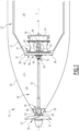
- a part of an underwater vehicle 10 is represented on the figure 1 .
- the underwater vehicle 10 is intended to be in an underwater environment, for example sea water.
- the underwater vehicle 10 is simply referred to as submarine 10.
- the submarine 10 includes an outer hull 20, a watertight hull 22 and a propulsion chain 26.
- a longitudinal direction L is defined for the submarine 10.
- the longitudinal direction L is the direction in which a propulsion force of the propulsion chain 26 is intended to be produced.
- the outer hull 20 forms an outer structure of the submarine 10 delimiting an inner space 27.
- the outer hull 20 is intended to be in direct contact with the underwater environment.
- the interior space 27 comprises an immersed space 28 and a sealed space 29.
- the immersed space 28 is delimited by an inner surface of the outer hull 20 and an outer surface of the sealed hull 22.
- the sea water circulates in the submerged space 28.
- the outer shell 20 includes a rear frame 30, corresponding to the rear end of the outer shell 20.
- the rear frame 30 includes axisymmetric structures.
- the watertight hull 22 is located in the interior space 27.
- the watertight hull 22 is an axisymmetric structure delimiting a watertight space 29 of the submarine 10.
- the crew and navigation instruments of the submarine 10 are located in the sealed space 29.
- the sealed space 29 is impermeable with respect to the exterior of the submarine 10.
- the watertight hull 22 comprises a rear bulkhead 31 and a supporting structure 32.
- the rear partition 31 is a wall at the rear of the watertight shell 22 delimiting a hole 33.
- the load-bearing structure 32 is a structure comprising a rear surface 42.
- the load-bearing structure 32 is rigidly fixed to the rear bulkhead 31.
- the load-bearing structure 32 is bolted to the rear bulkhead 31.
- the load-bearing structure 32 is the rear end of the waterproof shell 22.
- the support structure 32 defines an opening 36.
- the opening 36 is configured to receive part of the propulsion chain 26.
- the supporting structure 32 comprises a coaming 40.
- the coaming 40 is a structure projecting from the rear surface 42 of the supporting structure 32 in the longitudinal direction L.
- the support structure 32 is rigidly fixed to the sealed shell 22.
- the support structure 32 is fixed by screws 38 to the sealed shell 22 as visible on the figure 1 .
- Any gap between the sealed shell 22 and the supporting structure 32 is, for example, sealed off by a sealing compound, not shown.
- the load-bearing structure 32 is capable of transmitting forces between the sealed hull 22 and the propulsion chain 26.
- the propulsion chain 26 is configured to generate a force for propelling the submarine 10.
- the propulsion chain 26 includes a propeller 50, a drive shaft 52, a drive motor 54, a junction 56, a rear bearing 58 and a front bearing 59.
- the propeller 50 comprises a circular crown 60 and a plurality of blades 61 fixed on the crown 60.
- the propeller 50 is configured to rotate around an axis of rotation R and to generate a propulsion force in the longitudinal direction L.
- the axis of rotation R is parallel to the longitudinal direction L.
- the axis of rotation R is defined as the axis around which the drive shaft 52 is intended to rotate relative to the watertight hull 22 of the submarine. 10.
- the drive shaft 52 is a propeller shaft connected to the propeller 50.
- the drive shaft 52 is, for example, a cylindrical shaft with a circular base extending along the direction of the cylinder.
- the circular base has, for example, a radius between 30 millimeters (mm) and 200 mm, preferably between 80 mm and 120 mm.
- the drive shaft 52 extends between a rear end 62 and a front end 63 in the longitudinal direction L.
- the rear end 62 of the drive shaft 52 is rigidly fixed to the propeller 50.
- the front end 63 of drive shaft 52 is attached to junction 56.
- the drive shaft 52 passes through the support structure 32, through the opening 36.
- Motor 54 is, for example, an electric motor.
- the motor 54 comprises a stator and a rotor configured to rotate around the axis of rotation R.
- the rotor is fixed to a motor shaft 64.
- the motor 54 is rigidly fixed to the supporting structure 32.
- the stator of the motor 54 is rigidly fixed to a fixing 65.
- the fixing 65 is fixed to the supporting structure 32.
- the motor 54 is centered on the axis of rotation R.
- Junction 56 is a resilient coupling between drive shaft 52 and motor shaft 64.
- junction 56 comprises, for example, a ball joint received by two mechanical blocks respectively fixed to the drive shaft 52 and to the motor shaft 64.
- the ball joint is lubricated.
- Junction 56 is configured to tolerate rotations of drive shaft 52 and motor shaft 64 around the ball joint. Further, junction 56 is configured to accommodate movement of drive shaft 52 relative to motor shaft 64.
- junction 56 is, for example, elastically deformable in the longitudinal direction L and/or transversely.
- the junction 56 comprises a double ball joint.
- a double ball joint comprises two ball joints forming a cardan suspension.
- the aft bearing 58 is a bearing immersed in seawater.
- the aft bearing 58 is configured to be cooled by seawater.
- the rear bearing 58 is fixed to a metal structure 66.
- the metal structure 66 is a bearing bracket fixed by screws to the outer shell 20.
- the metal structure 66 is fixed to the rear frame 30 of the outer shell 20.
- the metal structure 66 is bolted to the rear frame 30.
- the metal structure 66 is removable.
- the rear bearing 58 is intended to be in rolling contact with the drive shaft 52.
- rolling contact is meant a lubricated connection between two elements configured to rotate relative to each other.
- Aft bearing 58 is configured to transmit forces between drive shaft 52 and outer shell 20.
- aft bearing 58 is configured to transmit propulsion forces.
- the front bearing 59 is a sealed bearing.
- the front bearing 59 is fixed to the support structure 32.
- the front bearing 59 is intended to be in rolling contact with the drive shaft 52.
- the front bearing 59 is centered on the support structure 32, with respect to the axis of rotation R.
- the front bearing 59 is intended to transmit forces between the bearing structure 32 and the drive shaft 52.
- the front bearing 59 is configured to transmit longitudinal forces and transverse forces.
- the front bearing 59 is configured to transmit thrust forces in the longitudinal direction L.
- the front bearing 59 is, moreover, a carrier bearing intended to support the weight of the drive shaft 52.
- the front bearing 59 forms a main abutment configured to transmit the majority of the longitudinal forces.
- the front bearing 59 is configured to transmit all of the longitudinal forces.
- the front bearing 59 includes a housing 70, a sealing device and a plurality of bearings.
- the housing 70 is a metal casing housing the sealing device and the plurality of bearings.
- the casing 70 is centered and bolted to the supporting structure 32.
- the sealing device is a lip seal.
- the sealing device comprises a first mechanical seal attached to the drive shaft 52 and a second seal attached to the front bearing housing 59.
- the first seal is supported on the second seal by springs fixed to the drive shaft 52 and arranged in the submerged space 28.
- the sealing device further comprises a sewer box, configured to recover any leakage of sea water passing between the first seal and second seal.
- the sewer box is located in the sealed space 29, inside the sealed shell 22.
- the first lining and the second lining are in sliding contact with each other.
- sliding contact it is understood that the linings are in physical contact with one another and that the first lining is capable of rotating relative to the second lining.
- the sealing device forms a fluidic barrier between the interior space 27 and the sealed space 29.
- the sealing device is configured to prevent circulation of a fluid between the interior space 27 and the exterior of the watertight hull 22.
- the sealing device is configured to be cooled by direct heat exchange with the seawater circulating in the submerged space 28 between the sealed hull 22 and the outer hull 20.
- Each bearing of the plurality of bearings is greased and configured to operate in a sealed environment.
- Each bearing is centered with respect to the axis of rotation R.
- Each bearing includes rings and rollers.
- Each roller is configured to rotate around an axis of rotation.
- the axis of rotation of a roll of the bearing is inclined with respect to the axis of rotation of another roll of the bearing.
- Two rollers are respectively arranged conically.
- the sealing device is arranged very close to the bearings in the longitudinal direction L.
- the sealing device and the plurality of bearings are spaced apart from each other by a distance of less than 200 millimeters in the longitudinal direction L , preferably less than 100 millimeters.
- the operation of the submarine 10 is now described.
- the propulsion of the submarine 10 by the propulsion chain 26 is described.
- Motor 54 rotates rotor and motor shaft 64 around axis of rotation R. Through junction 56, drive shaft 52 and propeller 50 are driven.
- transverse forces A1 are applied during propulsion.
- the rear bearing 58 only transmits transverse forces between the propulsion chain 26 and the outer shell 20.
- the rear bearing 58 does not transmit longitudinal forces.
- transverse forces A1, A2 are perpendicular to the longitudinal forces B.
- the rotation of the propeller 50 generates a thrust in the longitudinal direction L which causes a displacement of the submarine 10.
- the longitudinal forces B are in particular thrust forces.
- the front bearing 59 transmits transverse forces and longitudinal forces between the propulsion chain 26 and the watertight hull 22. In the example shown in the picture 2 , all of the longitudinal forces between the sealed shell 22 and the drive shaft 52 are transmitted by the front bearing 59.
- the rear bearing 58 forms a rear support and the front bearing 59 forms a front support for the propulsion chain 26.
- the front support and the rear support are the only supports between the propulsion chain 26 d on the one hand and the outer shell 20 and the sealed shell 22 on the other hand.
- the propulsion chain 26 thus forms an isostatic system.
- the submarine 10 as described has a number of advantages.
- the propulsion chain 26 is particularly compact.
- the length of the propulsion chain 26 in the longitudinal direction L is reduced. As a result, more space is available in the watertight shell 22.
- the engine 54 of the figure 1 is carried by the load-bearing structure 32.
- the sealed hull 22 and the outer hull 20 deform transversely.
- the motor 54 remains, during a deformation of the sealed shell 22 in immersion, centered on the axis of rotation R and centered with respect to the front bearing 59.
- the propulsion chain 26 remains centered with respect to a central axis of the watertight hull 22 at any depth.
- the front bearing 59 remains centered with respect to the axis of rotation R, the mechanical load on the front bearing 59 is reduced. As a result, the submarine 10 has improved acoustic discretion. In addition, the front bearing 59 has an increased service life.
- a transverse displacement of a support does not lead to an off-centering of the front bearing 59 or of the rear bearing 58.
- the sealing device is arranged very close to the bearings, when the sealed shell 22 is deformed while submerged, the first lining moves very little with respect to the second lining of the sealing device. Consequently, the sealing device is less fatigued and has a longer service life.
- the sealing device and the plurality of bearings are spaced apart by a distance less than 200 millimeters in the longitudinal direction L, preferably less than 100 millimeters.
- the propulsion chain 26 is simplified, in particular because the front bearing 59 includes the sealing device and bearings forming a thrust bearing and a bearing.
- the cumbersome casings supporting the engine in the state of the art are eliminated, which saves space in the sealed shell 22.
- the casing supporting the main abutment is eliminated, this casing being in practice difficult to rigidify.
- the assembly and disassembly of the propulsion chain 26 is made simpler.
- the submarine 10 allows assembly or disassembly of the propulsion chain 26 from the rear of the submarine 10. Consequently, maintenance in particular is simplified.
- the propulsion chain 26 is disassembled from a stern, the aft end of the submarine 10, to the rear.
- the propeller 50 is unscrewed and slid backwards.
- the propeller is slid along the longitudinal direction L towards the outside of the underwater vehicle 10.
- the rear bearing 58 is slid towards the rear, towards the outside of the underwater vehicle 10.
- drive shaft 52, forward bearing 59, and junction 56 are slid rearward, outboard of underwater vehicle 10.
- the support structure 32 is unscrewed from the sealed shell 22 and the support structure 32, the attachment 65 and the motor 54 are disassembled towards the rear.
- the entire propulsion chain 26 is disassembled towards the rear of the submarine 10.
- motor 54 and attachment 65 are introduced into watertight space 29 through the stern.
- the support structure 32 is fixed to the attachment 65 and the support structure 32 is screwed to the waterproof shell 22.
- the junction 56, the drive shaft 52 and the front bearing 59 are introduced through the stern.
- the front bearing 59 is fixed to the carrier structure 32 and the junction 56 is connected to the motor shaft 64.
- the rear bearing 58 is mounted on the drive shaft 52.
- the propeller 50 is screwed to the drive shaft 52.
- propulsion chain 26 can be assembled outside the submarine 10, this makes it possible to pre-assemble or test the propulsion chain 26 in the workshop, independently of an assembly of the submarine 10.
- the assembly and disassembly process makes it possible to easily replace the propulsion chain 26 in order to adapt, for example, the operational needs of the submarine 10 or to replace a defective propulsion chain 26 .
- the accessibility for maintenance of the propulsion chain 26 is improved.
Description
La présente invention concerne une chaîne cinématique d'un véhicule sous-marin. L'invention concerne également un véhicule sous-marin et un procédé de démontage d'une telle chaîne cinématique.The present invention relates to a kinematic chain of an underwater vehicle. The invention also relates to an underwater vehicle and a method for dismantling such a kinematic chain.
L'invention concerne le domaine des véhicules sous-marins et plus particulièrement le domaine de la propulsion sous-marine.The invention relates to the field of underwater vehicles and more particularly to the field of underwater propulsion.
Le document
Il est connu des véhicules sous-marins comprenant une coque extérieure et une coque étanche entourée par la coque extérieure. La coque étanche comprend une cloison arrière formant une barrière entre un milieu immergé, accessible pour un fluide provenant d'un extérieur du véhicule sous-marin, et un milieu intérieur de la coque étanche, non accessible au fluide.Underwater vehicles comprising an outer hull and a sealed hull surrounded by the outer hull are known. The watertight hull comprises a rear partition forming a barrier between an immersed environment, accessible to a fluid coming from outside the underwater vehicle, and an interior environment of the watertight hull, not accessible to the fluid.
De tels sous-marins comprennent des chaînes cinématiques de propulsion comprenant une hélice connectée à un arbre d'entraînement tournant qui est entraîné par un moteur disposé à l'intérieur de la coque étanche. L'arbre d'entraînement est en contact rotatif avec un palier immergé supporté par la coque extérieure, avec un autre palier immergé supporté par la cloison arrière et un palier porteur disposé à l'intérieur de la coque étanche. Les forces de propulsion entre l'arbre d'entraînement et la coque étanche proviennent de l'hélice et sont transférées par le palier porteur qui comprend une butée principale. Le palier porteur, la butée principale et le moteur sont fixés sur des carlingages de la coque étanche, qui sont soudés dans une partie basse d'un compartiment de propulsion dans la coque étanche.Such submarines comprise kinematic propulsion chains comprising a propeller connected to a rotating drive shaft which is driven by a motor disposed inside the watertight hull. The drive shaft is in rotational contact with one submerged bearing supported by the outer hull, with another submerged bearing supported by the aft bulkhead, and a carrier bearing disposed within the watertight hull. The propulsive forces between the drive shaft and the watertight hull come from the propeller and are transferred by the carrier bearing which includes a main thrust bearing. The carrier bearing, the main thrust bearing and the motor are fixed to the casings of the watertight hull, which are welded to a lower part of a propulsion compartment in the watertight hull.
Cependant, lors de l'immersion du véhicule sous-marin, la coque étanche se déforme. Les éléments de la chaîne de propulsion se déplacent alors relativement l'un par rapport à l'autre. Par exemple, le palier porteur, la butée principale et le moteur se déplacent verticalement lors d'une compression de la coque étanche. En conséquence, la chaîne de propulsion se décentre par rapport à un axe de rotation de l'hélice à cause de ces déformations. Certains éléments, notamment ceux de la chaîne de propulsion, reçoivent des surcharges. Les surcharges entraînent un vieillissement rapide de ces éléments. En outre, le décentrement de la chaîne de propulsion entraîne une émission sonore élevée de la chaîne et entraîne une fuite d'eau de mer vers l'intérieur de la coque étanche.However, during the immersion of the underwater vehicle, the waterproof hull is deformed. The elements of the propulsion chain then move relative to one another. For example, the carrier bearing, the main thrust bearing and the motor move vertically during compression of the sealed shell. Consequently, the propulsion chain becomes off-center relative to an axis of rotation of the propeller because of these deformations. Certain elements, in particular those of the propulsion chain, receive overloads. Overloads lead to rapid aging of these elements. In addition, the off-centering of the propulsion chain results in a high noise emission from the chain and causes seawater to leak into the interior of the watertight hull.
Il existe donc un besoin pour un véhicule sous-marin présentant un comportement amélioré lors de l'immersion et présentant une meilleure discrétion acoustique.There is therefore a need for an underwater vehicle exhibiting improved behavior during immersion and exhibiting better acoustic discretion.
Pour cela, la présente description porte sur un véhicule sous-marin selon la revendication 1.For this, the present description relates to an underwater vehicle according to claim 1.
Suivant des modes de réalisation particuliers, le véhicule sous-marin est selon l'une quelconque des revendications 2 à 8.According to particular embodiments, the underwater vehicle is according to any one of claims 2 to 8.
La présente description se rapporte également à un procédé de démontage selon la revendication 9.The present description also relates to a dismantling method according to claim 9.
D'autres caractéristiques et avantages de l'invention apparaîtront à la lecture de la description qui suit de modes de réalisation de l'invention, donnés à titre d'exemple uniquement et en référence aux dessins qui sont :
-
figure 1 , une vue schématique d'une partie d'un sous-marin comprenant une chaîne de propulsion, et -
figure 2 , une vue schématique d'une partie du sous-marin montrant des efforts présents lors d'une propulsion du véhicule sous-marin.
-
figure 1 , a schematic view of part of a submarine including a propulsion chain, and -
figure 2 , a schematic view of part of the submarine showing the forces present during propulsion of the underwater vehicle.
Une partie d'un véhicule sous-marin 10 est représentée sur la
Le sous-marin 10 comprend une coque extérieure 20, une coque étanche 22 et une chaîne de propulsion 26.The
Il est défini une direction longitudinale L pour le sous-marin 10. La direction longitudinale L est la direction selon laquelle une force de propulsion de la chaîne de propulsion 26 est destinée à être produite.A longitudinal direction L is defined for the
Dans la suite de la description, les expressions « transversalement » et « transversal » désignent toute direction perpendiculaire à la direction longitudinale L.In the rest of the description, the expressions "transversely" and "transverse" designate any direction perpendicular to the longitudinal direction L.
La coque extérieure 20 forme une structure extérieure du sous-marin 10 délimitant un espace intérieur 27. La coque extérieure 20 est destinée à être en contact direct avec l'environnement sous-marin.The
L'espace intérieur 27 comprend un espace immergé 28 et un espace étanche 29. L'espace immergé 28 est délimité par une surface intérieure de la coque extérieure 20 et une surface extérieure de la coque étanche 22. L'eau de mer circule dans l'espace immergé 28.The
La coque extérieure 20 comprend une charpente arrière 30, correspondant à l'extrémité arrière de la coque extérieure 20. La charpente arrière 30 comprend des structures axisymétriques.The
La coque étanche 22 est située dans l'espace intérieur 27. La coque étanche 22 est une structure axisymétrique délimitant un espace étanche 29 du sous-marin 10. Par exemple, l'équipage et des instruments de navigation du sous-marin 10 sont situés dans l'espace étanche 29. L'espace étanche 29 est imperméable par rapport à l'extérieur du sous-marin 10.The
La coque étanche 22 comprend une cloison arrière 31 et une structure porteuse 32.The
La cloison arrière 31 est un mur à l'arrière de la coque étanche 22 délimitant un trou 33.The
La structure porteuse 32 est une structure comprenant une surface arrière 42. La structure porteuse 32 est rigidement fixée à la cloison arrière 31. Par exemple, la structure porteuse 32 est boulonnée sur la cloison arrière 31.The load-bearing
La structure porteuse 32 est l'extrémité arrière de la coque étanche 22.The load-bearing
La structure porteuse 32 définit une ouverture 36. L'ouverture 36 est configurée pour recevoir une partie de la chaîne de propulsion 26.The
La structure porteuse 32 comprend un surbau 40. Le surbau 40 est une structure faisant saillie de la surface arrière 42 de la structure porteuse 32 selon la direction longitudinale L.The supporting
La structure porteuse 32 est rigidement fixée à la coque étanche 22. Par exemple, la structure porteuse 32 est fixée par des vis 38 à la coque étanche 22 comme visible sur la
La structure porteuse 32 est apte à transmettre des forces entre la coque étanche 22 et la chaîne de propulsion 26.The load-bearing
La chaîne de propulsion 26 est configurée pour générer une force de propulsion du sous-marin 10.The
La chaîne de propulsion 26 comprend une hélice 50, un arbre d'entraînement 52, un moteur d'entraînement 54, une jonction 56, un palier arrière 58 et un palier avant 59.The
L'hélice 50 comprend une couronne circulaire 60 et une pluralité de pales 61 fixées sur la couronne 60. L'hélice 50 est configurée pour tourner autour d'un axe de rotation R et de générer une force de propulsion selon la direction longitudinale L.The
L'axe de rotation R est parallèle à la direction longitudinale L. L'axe de rotation R est défini comme l'axe autour duquel l'arbre d'entraînement 52 est destiné à tourner par rapport à la coque étanche 22 du sous-marin 10.The axis of rotation R is parallel to the longitudinal direction L. The axis of rotation R is defined as the axis around which the
L'arbre d'entraînement 52 est un arbre porte-hélice connecté à l'hélice 50. L'arbre d'entraînement 52 est, par exemple, un arbre cylindrique à base circulaire s'étendant selon la direction du cylindre. La base circulaire présente, par exemple, un rayon compris entre 30 millimètres (mm) et 200 mm, de préférence compris entre 80 mm et 120 mm. L'arbre d'entraînement 52 s'étend entre une extrémité arrière 62 et une extrémité avant 63 selon la direction longitudinale L. L'extrémité arrière 62 de l'arbre d'entraînement 52 est rigidement fixée à l'hélice 50. L'extrémité avant 63 de l'arbre d'entraînement 52 est fixée à la jonction 56.The
L'arbre d'entraînement 52 traverse la structure porteuse 32, par l'ouverture 36.The
Le moteur 54 est, par exemple, un moteur électrique. Le moteur 54 comprend un stator et un rotor configuré pour tourner autour de l'axe de rotation R. Le rotor est fixé à un arbre moteur 64.
Le moteur 54 est rigidement fixé à la structure porteuse 32. Le stator du moteur 54 est rigidement fixé à une fixation 65. La fixation 65 est fixée à la structure porteuse 32. Le moteur 54 est centré sur l'axe de rotation R.The
La jonction 56 est un accouplement élastique entre l'arbre d'entraînement 52 et l'arbre moteur 64.
La jonction 56 comprend, par exemple, une rotule reçue par deux blocs mécaniques respectivement fixés à l'arbre d'entraînement 52 et à l'arbre moteur 64. La rotule est lubrifiée. La jonction 56 est configurée pour tolérer des rotations de l'arbre d'entraînement 52 et de l'arbre moteur 64 autour de la rotule. En outre, la jonction 56 est configurée pour tolérer un déplacement de l'arbre d'entraînement 52 par rapport à l'arbre moteur 64.The
La distance entre la rotule et chaque bloc mécanique est variable. La jonction 56 est, par exemple, déformable élastiquement selon la direction longitudinale L et/ou transversalement.The distance between the ball joint and each mechanical block is variable.
En variante, la jonction 56 comprend une double rotule. Une telle double rotule comprend deux rotules formant une suspension cardan.As a variant, the
Le palier arrière 58 est un palier immergé dans l'eau de mer. Le palier arrière 58 est configuré pour être refroidi par l'eau de mer.The
Le palier arrière 58 est fixé à une structure métallique 66. La structure métallique 66 est une chaise de palier fixée par des vis à la coque extérieure 20. La structure métallique 66 est fixée à la charpente arrière 30 de la coque extérieure 20. Par exemple, la structure métallique 66 est boulonnée sur la charpente arrière 30. La structure métallique 66 est amovible.The
Le palier arrière 58 est destiné à être en contact de roulement avec l'arbre d'entraînement 52.The
Par l'expression « contact de roulement », il est entendu une connexion lubrifiée entre deux éléments configurés pour tourner l'un par rapport à l'autre.By the term "rolling contact" is meant a lubricated connection between two elements configured to rotate relative to each other.
Le palier arrière 58 est configuré pour transmettre des forces entre l'arbre d'entraînement 52 et la coque extérieure 20. Par exemple, le palier arrière 58 est configuré pour transmettre des forces de propulsion.
Le palier avant 59 est un palier étanche. Le palier avant 59 est fixé à la structure porteuse 32. Le palier avant 59 est destiné à être en contact de roulement avec l'arbre d'entraînement 52. Le palier avant 59 est centré sur la structure porteuse 32, par rapport à l'axe de rotation R.The
Le palier avant 59 est destiné à transmettre des forces entre la structure porteuse 32 et l'arbre d'entraînement 52.The
Le palier avant 59 est configuré pour transmettre des efforts longitudinaux et des efforts transversaux.The
Par exemple, le palier avant 59 est configuré pour transmettre des efforts de poussée selon la direction longitudinale L. Le palier avant 59 est, en outre, un palier porteur destiné à supporter le poids de l'arbre d'entraînement 52.For example, the
De préférence, le palier avant 59 forme une butée principale configurée pour transmettre la majorité des efforts longitudinaux.Preferably, the front bearing 59 forms a main abutment configured to transmit the majority of the longitudinal forces.
Par l'expression « majorité des efforts », il est entendu plus de 50 % des forces correspondantes, et de préférence au moins 75 % des forces correspondantes.By the expression “majority of the efforts”, it is understood more than 50% of the corresponding forces, and preferably at least 75% of the corresponding forces.
Avantageusement, le palier avant 59 est configuré pour transmettre l'ensemble des efforts longitudinaux.Advantageously, the
Le palier avant 59 comprend un carter 70, un dispositif d'étanchéité et une pluralité de roulements.The
Le carter 70 est un boîtier métallique logeant le dispositif d'étanchéité et la pluralité de roulements. Le carter 70 est centré et boulonné sur la structure porteuse 32.The
Le dispositif d'étanchéité est un joint à lèvres. Le dispositif d'étanchéité comprend une première garniture mécanique fixée à l'arbre d'entraînement 52 et une deuxième garniture est fixée au carter du palier avant 59.The sealing device is a lip seal. The sealing device comprises a first mechanical seal attached to the
La première garniture est appuyée sur la deuxième garniture par des ressorts fixés sur l'arbre d'entraînement 52 et disposés à dans l'espace immergé 28.The first seal is supported on the second seal by springs fixed to the
Le dispositif d'étanchéité comprend, en outre, une caisse à égoutture, configurée pour récupérer une fuite éventuelle de l'eau de mer passant entre la première garniture et deuxième garniture. La caisse à égoutture est située dans l'espace étanche 29, à l'intérieur de la coque étanche 22.The sealing device further comprises a sewer box, configured to recover any leakage of sea water passing between the first seal and second seal. The sewer box is located in the sealed
La première garniture et deuxième garniture sont en contact glissant l'une avec l'autre.The first lining and the second lining are in sliding contact with each other.
Par l'expression « contact glissant », il est entendu que les garnitures sont en contact physique entre elles et que la première garniture est apte à tourner par rapport à la deuxième garniture.By the expression “sliding contact”, it is understood that the linings are in physical contact with one another and that the first lining is capable of rotating relative to the second lining.
Le dispositif d'étanchéité forme une barrière fluidique entre l'espace intérieur 27 et l'espace étanche 29. En d'autres termes, le dispositif d'étanchéité est configuré pour empêcher une circulation d'un fluide entre l'espace intérieur 27 et l'extérieur de la coque étanche 22.The sealing device forms a fluidic barrier between the
Le dispositif d'étanchéité est configuré pour être refroidi par échange thermique direct avec l'eau de mer circulant dans l'espace immergé 28 entre la coque étanche 22 et la coque extérieure 20.The sealing device is configured to be cooled by direct heat exchange with the seawater circulating in the submerged
Chaque roulement de la pluralité des roulements est graissé et configuré pour travailler dans un milieu étanche. Chaque roulement est centré par rapport à l'axe de rotation R.Each bearing of the plurality of bearings is greased and configured to operate in a sealed environment. Each bearing is centered with respect to the axis of rotation R.
Chaque roulement comprend des bagues et des rouleaux. Chaque rouleau est configuré pour tourner autour d'un axe de rotation. L'axe de rotation d'un rouleau du roulement est incliné par rapport à l'axe de rotation d'un autre rouleau du roulement. Deux rouleaux sont respectivement agencés de manière conique.Each bearing includes rings and rollers. Each roller is configured to rotate around an axis of rotation. The axis of rotation of a roll of the bearing is inclined with respect to the axis of rotation of another roll of the bearing. Two rollers are respectively arranged conically.
De préférence, le dispositif d'étanchéité est disposé très proche des roulements selon la direction longitudinale L. Par exemple, le dispositif d'étanchéité et la pluralité de roulements sont espacés entre eux d'une distance inférieure à 200 millimètres selon la direction longitudinale L, de préférence inférieure à 100 millimètres.Preferably, the sealing device is arranged very close to the bearings in the longitudinal direction L. For example, the sealing device and the plurality of bearings are spaced apart from each other by a distance of less than 200 millimeters in the longitudinal direction L , preferably less than 100 millimeters.
Le fonctionnement du sous-marin 10 est maintenant décrit. Notamment, la propulsion du sous-marin 10 par la chaîne de propulsion 26 est décrite.The operation of the
Le moteur 54 tourne le rotor et l'arbre moteur 64 autour de l'axe de rotation R. Par la jonction 56, l'arbre d'entraînement 52 et l'hélice 50 sont actionnés.
Sur la
Sur le palier arrière 58, des efforts transversaux A1 sont appliqués lors de la propulsion. Le palier arrière 58 transmet uniquement des forces transversales entre la chaîne de propulsion 26 et la coque extérieure 20. Le palier arrière 58 ne transmet pas des forces longitudinales.On the
Sur le palier avant 59, des efforts transversaux A2 et des efforts longitudinaux B sont appliqués.On the
Les efforts transversaux A1, A2 sont perpendiculaires aux efforts longitudinaux B.The transverse forces A1, A2 are perpendicular to the longitudinal forces B.
La rotation de l'hélice 50 génère une poussée selon la direction longitudinale L qui entraîne un déplacement du sous-marin 10. Les efforts longitudinaux B sont notamment des efforts de poussée.The rotation of the
Le palier avant 59 transmet des forces transversales et des forces longitudinales entre la chaîne de propulsion 26 et la coque étanche 22. Dans l'exemple représenté sur la
Le palier arrière 58 forme un appui arrière et le palier avant 59 forme un appui avant de la chaîne de propulsion 26. Dans l'exemple représenté, l'appui avant et l'appui arrière sont les uniques appuis entre la chaîne de propulsion 26 d'une part et la coque extérieure 20 et la coque étanche 22 d'autre part.The
La chaîne de propulsion 26 forme ainsi un système isostatique.The
Du fait de ce caractère isostatique le sous-marin 10 tel que décrit présente une pluralité d'avantages.Due to this isostatic character, the
Comme le dispositif d'étanchéité et les roulements sont disposés dans le carter 70, la chaîne de propulsion 26 est particulièrement compacte. En outre, la longueur de la chaîne de propulsion 26 selon la direction longitudinale L est réduite. En conséquence, plus d'espace est disponible dans la coque étanche 22.As the sealing device and the bearings are arranged in the
Contrairement à l'état de la technique, dans lequel le moteur est porté par des carlingages dans la coque étanche, le moteur 54 de la
Dans le sous-marin 10, la chaîne de propulsion 26 reste centrée par rapport à un axe central la coque étanche 22 à toute profondeur.In the
Comme le palier avant 59 reste centré par rapport à l'axe de rotation R, la charge mécanique sur le palier avant 59 est diminuée. En conséquence, le sous-marin 10 présente une discrétion acoustique améliorée. En outre, le palier avant 59 présente une durée de vie augmentée.As the
Le fait que les efforts longitudinaux et transversaux sont principalement transférés par le palier avant 59 permet ainsi d'éviter un décentrement de l'arbre d'entraînement 52 lors d'une déformation de la coque étanche 22 ou de la coque extérieure 20 en immersion du sous-marin 10.The fact that the longitudinal and transverse forces are mainly transferred by the
Un déplacement transversal d'un appui n'entraîne pas un décentrement du palier avant 59 ou du palier arrière 58.A transverse displacement of a support does not lead to an off-centering of the
Comme le moteur 54 est fixé à la structure porteuse 32, le déplacement relatif entre moteur 54 et palier avant 59, également fixé à la structure porteuse 32, est réduit. En conséquence, la chaîne de propulsion 26 est moins sensible aux contractions de la coque étanche 22.As the
En outre, comme le dispositif d'étanchéité est disposé très proche des roulements, lors d'une déformation de la coque étanche 22 en immersion, la première garniture se déplace très peu par rapport à la deuxième garniture du dispositif d'étanchéité. En conséquence, le dispositif d'étanchéité est moins fatigué et présente une durée de vie plus importante.Furthermore, as the sealing device is arranged very close to the bearings, when the sealed
Par exemple, le dispositif d'étanchéité et la pluralité de roulements sont espacés entre eux d'une distance inférieure à 200 millimètres selon la direction longitudinale L, de préférence inférieure à 100 millimètres.For example, the sealing device and the plurality of bearings are spaced apart by a distance less than 200 millimeters in the longitudinal direction L, preferably less than 100 millimeters.
Comme le dispositif de d'étanchéité est refroidi par échange thermique direct avec l'eau de mer, aucune pompe d'eau n'est nécessaire pour refroidir le dispositif de d'étanchéité.As the sealing device is cooled by direct heat exchange with sea water, no water pump is needed to cool the sealing device.
En outre, la chaîne de propulsion 26 est simplifiée, en particulier parce que le palier avant 59 comprend le dispositif de d'étanchéité et des roulements formant une butée et un palier. De plus, les carlingages encombrants supportant le moteur dans l'état de la technique sont supprimés, ce qui permet de gagner de l'espace dans la coque étanche 22. En outre, le carlingage supportant la butée principale est supprimé, ce carlingage étant en pratique difficile à rigidifier.In addition, the
Le montage et démontage de la chaîne de propulsion 26 est rendu plus simple. En particulier, le sous-marin 10 permet un montage ou démontage de la chaîne de propulsion 26 par l'arrière du sous-marin 10. En conséquence, notamment la maintenance est simplifiée.The assembly and disassembly of the
Pour illustrer une telle simplicité, un procédé de démontage de la chaîne de propulsion 26 est maintenant décrit.To illustrate such simplicity, a method of dismantling the
Lors du procédé de démontage, la chaîne de propulsion 26 est démontée d'une poupe, l'extrémité arrière du sous-marin 10, vers l'arrière.During the disassembly process, the
Lors d'une première étape, l'hélice 50 est dévissée et glissée vers l'arrière. L'hélice est glissée selon la direction longitudinale L vers l'extérieur du véhicule sous-marin 10. Lors d'une deuxième étape, le palier arrière 58 est glissé vers l'arrière, vers l'extérieur du véhicule sous-marin 10. Lors d'une troisième étape, l'arbre d'entraînement 52, le palier avant 59 et la jonction 56 sont glissés vers l'arrière, vers l'extérieur du véhicule sous-marin 10.During a first step, the
Puis, la structure porteuse 32 est dévissée de la coque étanche 22 et la structure porteuse 32, la fixation 65 et le moteur 54 sont démontés vers l'arrière.Then, the
A la fin du procédé de démontage, l'ensemble de la chaîne de propulsion 26 est démonté vers l'arrière du sous-marin 10.At the end of the disassembly process, the
Un procédé de montage de la chaîne de propulsion 26 est maintenant décrit.A method of mounting the
D'abord, le moteur 54 et la fixation 65 sont introduits dans l'espace étanche 29 par la poupe. La structure porteuse 32 est fixée à la fixation 65 et la structure porteuse 32 est vissée à la coque étanche 22.First,
Puis, la jonction 56, l'arbre d'entraînement 52 et le palier avant 59 sont introduits par la poupe. Le palier avant 59 est fixé à la structure porteuse 32 et la jonction 56 est connecté à l'arbre moteur 64. Lors de l'étape suivante de montage, le palier arrière 58 est monté sur l'arbre d'entraînement 52. Lors de l'étape suivante de montage, l'hélice 50 est vissée à l'arbre d'entraînement 52.Then, the
Comme la chaîne de propulsion 26 est assemblable à l'extérieur du sous-marin 10, cela permet de pré-monter ou tester la chaîne de propulsion 26 en atelier, indépendamment d'un montage du sous-marin 10.As the
En outre, le procédé de montage et de démontage permet de remplacer facilement la chaîne de propulsion 26 afin d'adapter par exemple des besoins opérationnels du sous-marin 10 ou de substituer une chaîne de chaîne de propulsion 26 défaillante. En outre, l'accessibilité pour une maintenance de la chaîne de propulsion 26 est améliorée.In addition, the assembly and disassembly process makes it possible to easily replace the
Claims (9)
- A submarine vehicle (10) comprising an outer hull (20) and a sealed hull (22) surrounded by the outer hull (20), the sealed hull (22) delimiting a sealed space (29) of the submarine vehicle (10), the sealed hull (22) including a supporting structure (32) delimiting an opening (36),the submarine vehicle (10) further comprising a propulsion chain (26) comprising:- a drive motor (54),- a drive shaft (52) driven by the drive motor (54), the drive shaft (52) extending in a longitudinal direction (L) and passing through the opening (36),- a propeller (50) rigidly fastened to the drive shaft (52),the propulsion chain (26) comprising at least one front bearing (59) in rolling contact with the drive shaft (52), the front bearing (59) being rigidly fastened to the supporting structure (32), the front bearing (59) being configured to transmit longitudinal forces between the drive shaft (52) and the supporting structure (32),the motor (54) being rigidly fastened to the supporting structure (32),the sealed hull (22) comprising a rear partition (31), the rear partition (31) being a wall at the back of the sealed hull (22) delimiting a hole (33), the supporting structure (32) being a structure comprising a rear surface (42), the supporting structure (32) being rigidly fastened to the rear partition (31).
- The submarine vehicle according to claim 1, wherein the front bearing (59) comprises a sealing device configured to prevent a circulation of a fluid between the sealed space (29) and a submerged space (28) outside the sealed hull (22).
- The submarine vehicle according to claim 1 or 2, wherein a motor shaft (64) is connected to the drive shaft (52) by means of a junction (56), the junction (56) being resiliently deformable at least in the longitudinal direction (L).
- The submarine vehicle according to any one of claims 1 to 3, wherein the front bearing (59) comprises a plurality of rolling bearings, each rolling bearing comprising rollers, each roller being configured to rotate about an axis of rotation, the rotation of a roller of the rolling bearing being inclined relative to the axis of rotation of another roller of the rolling bearing.
- The submarine vehicle according to claim 4, wherein the front bearing (59) comprises a sealing device configured to prevent a circulation of a fluid between the sealed space (29) and a submerged space (28) outside the sealed hull (22), and wherein the sealing device and the plurality of rolling bearings are spaced apart from one another by a distance of less than 200 millimeters in the longitudinal direction (L), preferably less than 100 millimeters.
- The submarine vehicle according to any one of claims 1 to 5, wherein the front bearing (59) is further configured to transmit transverse forces, the transverse forces being perpendicular to the longitudinal forces.
- The submarine vehicle according to any one of claims 1 to 6, wherein the submarine vehicle (10) comprises a rear bearing (58) fastened to the outer hull (20), the rear bearing (58) being in rolling contact with the drive shaft (52).
- The submarine vehicle according to any one of claims 1 to 7, wherein the supporting structure (32) comprises a coaming (40) protruding from a rear surface (42) of the supporting structure (32).
- A method for disassembling the propulsion chain (26) of a submarine vehicle (10) comprising an outer hull (20) and a sealed hull (22) surrounded by the outer hull (20), the sealed hull (22) delimiting a sealed space (29) of the submarine vehicle (10), the sealed hull (22) including a supporting structure (32) delimiting an opening (36),
the submarine vehicle (10) further comprising a propulsion chain (26) comprising:- a drive motor (54) rigidly fastened to the supporting structure (32),- a drive shaft (52) driven by the drive motor (54), the drive shaft (52) extending in a longitudinal direction (L) and passing through the opening (36),- a propeller (50) rigidly fastened to the drive shaft (52), and- at least one front bearing (59) in rolling contact with the drive shaft (52), the front bearing (59) being rigidly fastened to the supporting structure (32), the front bearing (59) being configured to transmit longitudinal forces between the drive shaft (52) and the supporting structure (32), the sealed hull (22) comprising a rear partition (31), the rear partition (31) being a wall at the back of the sealed hull (22) delimiting a hole (33), the supporting structure (32) being a structure comprising a rear surface (42), the supporting structure (32) being rigidly fastened to the rear partition (31), the method comprising:- sliding the propeller (50) in the longitudinal direction (L) toward the outside of the submarine vehicle (10),- sliding the rear bearing (58) toward the outside of the submarine vehicle (10),- sliding at least the drive shaft (52) and the front bearing (59) toward the outside.
Applications Claiming Priority (2)
| Application Number | Priority Date | Filing Date | Title |
|---|---|---|---|
| FR1701198A FR3073816B1 (en) | 2017-11-20 | 2017-11-20 | SUBMARINE VEHICLE COMPRISING A PROPULSION CHAIN AND METHOD THEREOF |
| PCT/EP2018/081809 WO2019097061A1 (en) | 2017-11-20 | 2018-11-19 | Submarine vehicle comprising a propulsion chain, and associated method |
Publications (2)
| Publication Number | Publication Date |
|---|---|
| EP3713840A1 EP3713840A1 (en) | 2020-09-30 |
| EP3713840B1 true EP3713840B1 (en) | 2023-05-31 |
Family
ID=61801990
Family Applications (1)
| Application Number | Title | Priority Date | Filing Date |
|---|---|---|---|
| EP18800978.1A Active EP3713840B1 (en) | 2017-11-20 | 2018-11-19 | Submarine vehicle comprising a propulsion chain, and associated method |
Country Status (5)
| Country | Link |
|---|---|
| EP (1) | EP3713840B1 (en) |
| AU (1) | AU2018368622A1 (en) |
| FR (1) | FR3073816B1 (en) |
| IL (1) | IL274497A (en) |
| WO (1) | WO2019097061A1 (en) |
Families Citing this family (1)
| Publication number | Priority date | Publication date | Assignee | Title |
|---|---|---|---|---|
| DE102021208362A1 (en) * | 2021-08-02 | 2023-02-02 | Thyssenkrupp Ag | Submarine with a thrust bearing for coupling the propulsion forces from the drive shaft into the pressure hull |
Family Cites Families (7)
| Publication number | Priority date | Publication date | Assignee | Title |
|---|---|---|---|---|
| FR1330724A (en) * | 1961-06-27 | 1963-06-28 | Ile D Etudes Et De Rech S Sous | Submerged gear, in particular personal diving gear, powered by the pressure of the immersion |
| JPH01226489A (en) * | 1988-03-07 | 1989-09-11 | Ishikawajima Harima Heavy Ind Co Ltd | Propulsion unit of submarine boat |
| RU2197408C2 (en) * | 2001-01-19 | 2003-01-27 | Григорчук Владимир Степанович | Submersible vehicle with single engine for surface and underwater running |
| CN101549748A (en) * | 2008-04-02 | 2009-10-07 | 尚德敏 | Submarine propulsion device free from dependence on air |
| DE102008018420A1 (en) * | 2008-04-10 | 2009-10-15 | Siemens Aktiengesellschaft | Drive device with two drive motors for a ship |
| DE102010004124A1 (en) * | 2010-01-07 | 2011-07-14 | Howaldtswerke-Deutsche Werft GmbH, 24143 | submarine |
| CN202130563U (en) * | 2011-05-16 | 2012-02-01 | 哈尔滨工程大学 | Pneumatic micro sightseeing submarine propulsion device |
-
2017
- 2017-11-20 FR FR1701198A patent/FR3073816B1/en active Active
-
2018
- 2018-11-19 WO PCT/EP2018/081809 patent/WO2019097061A1/en unknown
- 2018-11-19 AU AU2018368622A patent/AU2018368622A1/en active Pending
- 2018-11-19 EP EP18800978.1A patent/EP3713840B1/en active Active
-
2020
- 2020-05-06 IL IL274497A patent/IL274497A/en unknown
Also Published As
| Publication number | Publication date |
|---|---|
| FR3073816B1 (en) | 2019-11-29 |
| WO2019097061A1 (en) | 2019-05-23 |
| EP3713840A1 (en) | 2020-09-30 |
| IL274497A (en) | 2020-06-30 |
| AU2018368622A1 (en) | 2020-05-28 |
| FR3073816A1 (en) | 2019-05-24 |
Similar Documents
| Publication | Publication Date | Title |
|---|---|---|
| JP5266543B2 (en) | Counter-rotating propeller marine propulsion device | |
| KR101313585B1 (en) | Propulsion apparatus for ship, and ship having the same | |
| EP3713840B1 (en) | Submarine vehicle comprising a propulsion chain, and associated method | |
| FR2524414A1 (en) | MARINE PROPULSION DEVICE WITH SOLUBLE ANODE ASSOCIATED WITH THE STOP PAD | |
| US7841290B1 (en) | Marine shaftless external propulsor | |
| EP0009449B1 (en) | Bearing for ambivalent centrifugal pump | |
| KR101380650B1 (en) | Propulsion apparatus for ship, and ship having the same | |
| KR20100123409A (en) | Ship's propeller shaft | |
| KR20160116224A (en) | Propulsion apparatus for ship | |
| EP3237244A1 (en) | Hydraulic torque motor | |
| EP3244034B1 (en) | Internal combustion engine comprising a coolant pump | |
| KR101380662B1 (en) | Propulsion apparatus for ship and ship having the same | |
| KR101617028B1 (en) | Propulsion apparatus for ship, and ship having the same | |
| JP5037374B2 (en) | Lubrication structure of counter rotating seal device | |
| KR101523378B1 (en) | Pod-type propulsion unit for a ship | |
| WO2019110685A1 (en) | Device for propelling a navigational seacraft, and navigational seacraft provided with such a device | |
| KR101608190B1 (en) | Propulsion apparatus for ship, and ship having the same | |
| KR101661939B1 (en) | Propulsion apparatus for ship, and ship having the same | |
| US6250979B1 (en) | Boat drive with variable-pitch propeller | |
| KR101571423B1 (en) | Propulsion apparatus for ship, and ship having the same | |
| EP1028263A1 (en) | Coupling for pump and pump motor | |
| CN116280146A (en) | Magnetic transmission-based stern integrated propulsion device | |
| KR101652223B1 (en) | Propulsion apparatus for ship, and ship having the same | |
| FR2697598A1 (en) | Protective seal for rotor shaft of immersed water pump e.g. for central heating - comprises elastic ring with lip preventing ingress of solid particles past rotor shaft surface | |
| CN116424537A (en) | Still water balance type thrust bearing, ship propulsion system and underwater vehicle |
Legal Events
| Date | Code | Title | Description |
|---|---|---|---|
| STAA | Information on the status of an ep patent application or granted ep patent |
Free format text: STATUS: UNKNOWN |
|
| STAA | Information on the status of an ep patent application or granted ep patent |
Free format text: STATUS: THE INTERNATIONAL PUBLICATION HAS BEEN MADE |
|
| PUAI | Public reference made under article 153(3) epc to a published international application that has entered the european phase |
Free format text: ORIGINAL CODE: 0009012 |
|
| STAA | Information on the status of an ep patent application or granted ep patent |
Free format text: STATUS: REQUEST FOR EXAMINATION WAS MADE |
|
| 17P | Request for examination filed |
Effective date: 20200515 |
|
| AK | Designated contracting states |
Kind code of ref document: A1 Designated state(s): AL AT BE BG CH CY CZ DE DK EE ES FI FR GB GR HR HU IE IS IT LI LT LU LV MC MK MT NL NO PL PT RO RS SE SI SK SM TR |
|
| AX | Request for extension of the european patent |
Extension state: BA ME |
|
| DAV | Request for validation of the european patent (deleted) | ||
| DAX | Request for extension of the european patent (deleted) | ||
| STAA | Information on the status of an ep patent application or granted ep patent |
Free format text: STATUS: EXAMINATION IS IN PROGRESS |
|
| 17Q | First examination report despatched |
Effective date: 20220111 |
|
| GRAP | Despatch of communication of intention to grant a patent |
Free format text: ORIGINAL CODE: EPIDOSNIGR1 |
|
| STAA | Information on the status of an ep patent application or granted ep patent |
Free format text: STATUS: GRANT OF PATENT IS INTENDED |
|
| INTG | Intention to grant announced |
Effective date: 20221219 |
|
| GRAS | Grant fee paid |
Free format text: ORIGINAL CODE: EPIDOSNIGR3 |
|
| GRAA | (expected) grant |
Free format text: ORIGINAL CODE: 0009210 |
|
| STAA | Information on the status of an ep patent application or granted ep patent |
Free format text: STATUS: THE PATENT HAS BEEN GRANTED |
|
| AK | Designated contracting states |
Kind code of ref document: B1 Designated state(s): AL AT BE BG CH CY CZ DE DK EE ES FI FR GB GR HR HU IE IS IT LI LT LU LV MC MK MT NL NO PL PT RO RS SE SI SK SM TR |
|
| REG | Reference to a national code |
Ref country code: GB Ref legal event code: FG4D Free format text: NOT ENGLISH Ref country code: CH Ref legal event code: EP |
|
| REG | Reference to a national code |
Ref country code: AT Ref legal event code: REF Ref document number: 1570784 Country of ref document: AT Kind code of ref document: T Effective date: 20230615 Ref country code: DE Ref legal event code: R096 Ref document number: 602018050507 Country of ref document: DE |
|
| REG | Reference to a national code |
Ref country code: IE Ref legal event code: FG4D Free format text: LANGUAGE OF EP DOCUMENT: FRENCH |
|
| REG | Reference to a national code |
Ref country code: LT Ref legal event code: MG9D |
|
| REG | Reference to a national code |
Ref country code: NL Ref legal event code: MP Effective date: 20230531 |
|
| REG | Reference to a national code |
Ref country code: AT Ref legal event code: MK05 Ref document number: 1570784 Country of ref document: AT Kind code of ref document: T Effective date: 20230531 |
|
| PG25 | Lapsed in a contracting state [announced via postgrant information from national office to epo] |
Ref country code: SE Free format text: LAPSE BECAUSE OF FAILURE TO SUBMIT A TRANSLATION OF THE DESCRIPTION OR TO PAY THE FEE WITHIN THE PRESCRIBED TIME-LIMIT Effective date: 20230531 Ref country code: NO Free format text: LAPSE BECAUSE OF FAILURE TO SUBMIT A TRANSLATION OF THE DESCRIPTION OR TO PAY THE FEE WITHIN THE PRESCRIBED TIME-LIMIT Effective date: 20230831 Ref country code: ES Free format text: LAPSE BECAUSE OF FAILURE TO SUBMIT A TRANSLATION OF THE DESCRIPTION OR TO PAY THE FEE WITHIN THE PRESCRIBED TIME-LIMIT Effective date: 20230531 Ref country code: AT Free format text: LAPSE BECAUSE OF FAILURE TO SUBMIT A TRANSLATION OF THE DESCRIPTION OR TO PAY THE FEE WITHIN THE PRESCRIBED TIME-LIMIT Effective date: 20230531 |
|
| PG25 | Lapsed in a contracting state [announced via postgrant information from national office to epo] |
Ref country code: RS Free format text: LAPSE BECAUSE OF FAILURE TO SUBMIT A TRANSLATION OF THE DESCRIPTION OR TO PAY THE FEE WITHIN THE PRESCRIBED TIME-LIMIT Effective date: 20230531 Ref country code: PL Free format text: LAPSE BECAUSE OF FAILURE TO SUBMIT A TRANSLATION OF THE DESCRIPTION OR TO PAY THE FEE WITHIN THE PRESCRIBED TIME-LIMIT Effective date: 20230531 Ref country code: NL Free format text: LAPSE BECAUSE OF FAILURE TO SUBMIT A TRANSLATION OF THE DESCRIPTION OR TO PAY THE FEE WITHIN THE PRESCRIBED TIME-LIMIT Effective date: 20230531 Ref country code: LV Free format text: LAPSE BECAUSE OF FAILURE TO SUBMIT A TRANSLATION OF THE DESCRIPTION OR TO PAY THE FEE WITHIN THE PRESCRIBED TIME-LIMIT Effective date: 20230531 Ref country code: LT Free format text: LAPSE BECAUSE OF FAILURE TO SUBMIT A TRANSLATION OF THE DESCRIPTION OR TO PAY THE FEE WITHIN THE PRESCRIBED TIME-LIMIT Effective date: 20230531 Ref country code: IS Free format text: LAPSE BECAUSE OF FAILURE TO SUBMIT A TRANSLATION OF THE DESCRIPTION OR TO PAY THE FEE WITHIN THE PRESCRIBED TIME-LIMIT Effective date: 20230930 Ref country code: HR Free format text: LAPSE BECAUSE OF FAILURE TO SUBMIT A TRANSLATION OF THE DESCRIPTION OR TO PAY THE FEE WITHIN THE PRESCRIBED TIME-LIMIT Effective date: 20230531 Ref country code: GR Free format text: LAPSE BECAUSE OF FAILURE TO SUBMIT A TRANSLATION OF THE DESCRIPTION OR TO PAY THE FEE WITHIN THE PRESCRIBED TIME-LIMIT Effective date: 20230901 |
|
| PG25 | Lapsed in a contracting state [announced via postgrant information from national office to epo] |
Ref country code: FI Free format text: LAPSE BECAUSE OF FAILURE TO SUBMIT A TRANSLATION OF THE DESCRIPTION OR TO PAY THE FEE WITHIN THE PRESCRIBED TIME-LIMIT Effective date: 20230531 |
|
| PG25 | Lapsed in a contracting state [announced via postgrant information from national office to epo] |
Ref country code: SK Free format text: LAPSE BECAUSE OF FAILURE TO SUBMIT A TRANSLATION OF THE DESCRIPTION OR TO PAY THE FEE WITHIN THE PRESCRIBED TIME-LIMIT Effective date: 20230531 |
|
| PGFP | Annual fee paid to national office [announced via postgrant information from national office to epo] |
Ref country code: GB Payment date: 20231120 Year of fee payment: 6 |
|
| PG25 | Lapsed in a contracting state [announced via postgrant information from national office to epo] |
Ref country code: SM Free format text: LAPSE BECAUSE OF FAILURE TO SUBMIT A TRANSLATION OF THE DESCRIPTION OR TO PAY THE FEE WITHIN THE PRESCRIBED TIME-LIMIT Effective date: 20230531 Ref country code: SK Free format text: LAPSE BECAUSE OF FAILURE TO SUBMIT A TRANSLATION OF THE DESCRIPTION OR TO PAY THE FEE WITHIN THE PRESCRIBED TIME-LIMIT Effective date: 20230531 Ref country code: RO Free format text: LAPSE BECAUSE OF FAILURE TO SUBMIT A TRANSLATION OF THE DESCRIPTION OR TO PAY THE FEE WITHIN THE PRESCRIBED TIME-LIMIT Effective date: 20230531 Ref country code: PT Free format text: LAPSE BECAUSE OF FAILURE TO SUBMIT A TRANSLATION OF THE DESCRIPTION OR TO PAY THE FEE WITHIN THE PRESCRIBED TIME-LIMIT Effective date: 20231002 Ref country code: EE Free format text: LAPSE BECAUSE OF FAILURE TO SUBMIT A TRANSLATION OF THE DESCRIPTION OR TO PAY THE FEE WITHIN THE PRESCRIBED TIME-LIMIT Effective date: 20230531 Ref country code: DK Free format text: LAPSE BECAUSE OF FAILURE TO SUBMIT A TRANSLATION OF THE DESCRIPTION OR TO PAY THE FEE WITHIN THE PRESCRIBED TIME-LIMIT Effective date: 20230531 Ref country code: CZ Free format text: LAPSE BECAUSE OF FAILURE TO SUBMIT A TRANSLATION OF THE DESCRIPTION OR TO PAY THE FEE WITHIN THE PRESCRIBED TIME-LIMIT Effective date: 20230531 |
|
| PGFP | Annual fee paid to national office [announced via postgrant information from national office to epo] |
Ref country code: TR Payment date: 20231106 Year of fee payment: 6 Ref country code: IT Payment date: 20231109 Year of fee payment: 6 Ref country code: FR Payment date: 20231012 Year of fee payment: 6 Ref country code: DE Payment date: 20231107 Year of fee payment: 6 |
|
| REG | Reference to a national code |
Ref country code: DE Ref legal event code: R097 Ref document number: 602018050507 Country of ref document: DE |
|
| PLBE | No opposition filed within time limit |
Free format text: ORIGINAL CODE: 0009261 |
|
| STAA | Information on the status of an ep patent application or granted ep patent |
Free format text: STATUS: NO OPPOSITION FILED WITHIN TIME LIMIT |