EP3713835B1 - Jalousienwandanordnung für eine fahrgastbrücke - Google Patents
Jalousienwandanordnung für eine fahrgastbrücke Download PDFInfo
- Publication number
- EP3713835B1 EP3713835B1 EP18879225.3A EP18879225A EP3713835B1 EP 3713835 B1 EP3713835 B1 EP 3713835B1 EP 18879225 A EP18879225 A EP 18879225A EP 3713835 B1 EP3713835 B1 EP 3713835B1
- Authority
- EP
- European Patent Office
- Prior art keywords
- jalousi
- wire
- bridge
- wall
- roll
- Prior art date
- Legal status (The legal status is an assumption and is not a legal conclusion. Google has not performed a legal analysis and makes no representation as to the accuracy of the status listed.)
- Active
Links
Images

Classifications
-
- B—PERFORMING OPERATIONS; TRANSPORTING
- B64—AIRCRAFT; AVIATION; COSMONAUTICS
- B64F—GROUND OR AIRCRAFT-CARRIER-DECK INSTALLATIONS SPECIALLY ADAPTED FOR USE IN CONNECTION WITH AIRCRAFT; DESIGNING, MANUFACTURING, ASSEMBLING, CLEANING, MAINTAINING OR REPAIRING AIRCRAFT, NOT OTHERWISE PROVIDED FOR; HANDLING, TRANSPORTING, TESTING OR INSPECTING AIRCRAFT COMPONENTS, NOT OTHERWISE PROVIDED FOR
- B64F1/00—Ground or aircraft-carrier-deck installations
- B64F1/30—Ground or aircraft-carrier-deck installations for embarking or disembarking passengers
- B64F1/305—Bridges extending between terminal building and aircraft, e.g. telescopic, vertically adjustable
- B64F1/3055—Bridges extending between terminal building and aircraft, e.g. telescopic, vertically adjustable with hinged head interface between aircraft and passenger bridge
-
- E—FIXED CONSTRUCTIONS
- E01—CONSTRUCTION OF ROADS, RAILWAYS, OR BRIDGES
- E01D—CONSTRUCTION OF BRIDGES, ELEVATED ROADWAYS OR VIADUCTS; ASSEMBLY OF BRIDGES
- E01D15/00—Movable or portable bridges; Floating bridges
- E01D15/24—Bridges or similar structures, based on land or on a fixed structure and designed to give access to ships or other floating structures
-
- B—PERFORMING OPERATIONS; TRANSPORTING
- B63—SHIPS OR OTHER WATERBORNE VESSELS; RELATED EQUIPMENT
- B63B—SHIPS OR OTHER WATERBORNE VESSELS; EQUIPMENT FOR SHIPPING
- B63B27/00—Arrangement of ship-based loading or unloading equipment for cargo or passengers
- B63B27/14—Arrangement of ship-based loading or unloading equipment for cargo or passengers of ramps, gangways or outboard ladders ; Pilot lifts
- B63B2027/141—Arrangement of ship-based loading or unloading equipment for cargo or passengers of ramps, gangways or outboard ladders ; Pilot lifts telescopically extendable
-
- B—PERFORMING OPERATIONS; TRANSPORTING
- B63—SHIPS OR OTHER WATERBORNE VESSELS; RELATED EQUIPMENT
- B63B—SHIPS OR OTHER WATERBORNE VESSELS; EQUIPMENT FOR SHIPPING
- B63B27/00—Arrangement of ship-based loading or unloading equipment for cargo or passengers
- B63B27/14—Arrangement of ship-based loading or unloading equipment for cargo or passengers of ramps, gangways or outboard ladders ; Pilot lifts
Definitions
- the present invention relates to a passenger bridge, such as for a ship.
- the invention relates to a passenger bridge comprising a bridge head in turn comprising a cabin with a passenger entry/exit opening, and to a jalousi wall assembly of the bridge head.
- the invention further relates to such a jalousi wall assembly as such.
- a bridge head is a structure arranged at a distal end of a passenger bridge segment, comprising a cabin which rotatingly engages with a main body of the bridge head, typically by being displaced along an outer periphery of the said main body, such as in a horizontal plane, which periphery may be semi-circular. Via the cabin, passengers can pass between the passenger bridge and a door opening in a ship or the like.
- Such bridge heads are known from, inter alia, SE 1351035-9 .
- the horizontal turnability of the cabin accomplishes that the cabin can be horizontally pivoted in relation to said distal end of the passenger bridge, to allow various angles between the passenger bridge and the said door opening.
- bridge heads are equipped with folding jalousi walls, covering the sides of the bridge head which is not occupied by the cabin.
- the jalousi wall on one side of the cabin unfolds to become wider and the jalousi wall on the other side of the cabin folds to become narrower, so that the bridge head sides are covered by either jalousi wall or cabin at all times.
- jalousi wall is intended to denote a construction similar to that of a jalousi sliding door of a conventional jalousi cabinet. Hence, such a jalousi wall is intended for being slided, such as sideways, following a curved wall contour.
- a jalousi wall may comprise a number of elongated, rigid pieces, such as vertically arranged, that are joined together so that they are always parallel to each other but so that they can pivot in relation to each other in a way so that the jalousi wall can follow said wall contour as the jalousi wall is slided along said contour, such as horizontally.
- such jalousi wall folding mechanism is automatic, following the cabin movements.
- This is preferably the case also for a jalousi wall assembly according to the invention.
- the jalousi wall on either side of the cabin has a first respective end which is wound up on a respective vertically arranged roll with a vertical axis, while a respective opposite, second end of each jalousi wall is permanently fastened to the bridge head.
- the rolls are conventionally spring-loaded, so that the respective jalousi wall is wound up in the absence of a horizontal pulling force applied to an end part of the jalousi wall in question.
- This spring loading conventionally uses a torsion spring arranged inside the roll in question.
- the present invention uses a different approach to achieve such automatic operation of the jalousi wall.
- the conventional construction provides good performance in terms of folding and unfolding of the jalousi walls.
- it is complicated and time-consuming to access the torsion spring, such as for replacement of the torsion spring.
- US 3,402,412 A discloses a vestibule curtain reelings system for conveyance loaders.
- Ajalousi wall assembly comprises a wire tension system using a tensioning spring.
- the present invention solves the above described problems.
- the invention relates to a jalousi wall assembly according to claim 1.
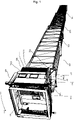
- Figure 1 illustrates a passenger bridge 100 according to the present invention.
- the passenger bridge 100 is preferably intended and arranged for taking walking passengers to and from a door opening in the hull of a ship, but may also be used for other purposes, such as taking passengers to and from an airplane.
- the passenger bridge 100 comprises at least one passenger bridge segment 110, 120, 130. In the Figures, three such segments 110, 120, 130 are shown. Preferably, the passenger bridge comprises at least two such segments. Preferably, the segments 110, 120, 130 are telescopically arranged in relation to each other, with a largest cross section segment 110 arranged at a first end of the passenger bridge 100 and a smallest cross section segment 130, also denoted "bridge end segment", arranged at a second, distal end of the passenger bridge 100. During use, passengers may move through the segments 110, 120, 130 in order, on their way to and from a bridge head 150 which is also comprised in the passenger bridge 100 and via which passengers can move into and out from the bridge 100, from or to a ship or the like.
- a bridge head 150 which is also comprised in the passenger bridge 100 and via which passengers can move into and out from the bridge 100, from or to a ship or the like.
- the bridge head 150 is arranged at, and connected to, a distal end 131 of the bridge end segment 130.
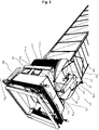
- the bridge head 150 in turn comprises a cabin 160 with an entry/exit door 161 for passengers.
- the cabin 160 is arranged to move about an outer periphery 152 of the bridge head 150, and comprises an entry/exit door 161 for passengers.
- the cabin 160 and its door 161 can move along said outer periphery 152 of the bridge head 150, allowing the passenger bridge 100 to cater for passenger transfer in selectable horizontal directions, by turning the cabin 160.
- the passenger bridge 100 comprises a cabin suspension 140, arranged to allow the cabin 160 to rotate in relation to the bridge head 150 about a vertical axis A1, in a horizontal swing plane P1. Such rotation is preferably possible across an angular interval of at least 45°, preferably at least 90°, and furthermore of at the most 270°, preferably at the most 180°.
- the cabin 160 is arranged to "rotate" in relation to the bridge head 150 does not imply full 360° rotations, but a rotary motion across a more limited angular interval.
- the suspension 140 is arranged to drive the cabin 160 in such rotary movement.
- This drive is controlled by a control device (not shown in the Figures), allowing an operator to manually or automatically direct the cabin 160 door 161 in a desired horizontal direction depending on operating conditions.
- the control device can preferably control this horizontal angle over a continuous spectrum of angles, as opposed to a limited number of discreet angular positions.
- the bridge head 150 comprises a jalousi wall assembly 170.
- the jalousi wall assembly 170 according to the invention is arranged for use as a wall assembly in a passenger bridge 100 according to the invention, and specifically in a bridge head 150 according to the invention. In other words, it is specifically adapted for such use.
- Such adaptations may, for instance, comprise adaptations in terms of dimensions, fastening points, strength and robustness.
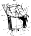
- the jalousi wall assembly 170 comprises a first jalousi wall 171, in turn having a first end 171a and a second end 171b.
- the first end 171a is arranged to be wound up on, and off from, a first roll 172.
- the first roll having a first vertical roll rotation axis A2, is arranged to wind the first jalousi wall 171 up, such as on a central metal cylinder to which the first end 171a is fastened, so that the jalousi wall 171 as a result forms a roll about the vertical axis A2.
- the roll 172 itself does not comprise a spring means, and would allow the jalousi wall 171 to be wound up onto or off from the roll 172 freely in the hypothetical case in which the jalousi wall 171 is not spring-loaded in any way.
- the second end 171b of the first jalousi wall 171 is arranged to be fastened, and is preferably in fact fastened, to the passenger bridge 100, preferably to the bridge head 150, preferably at a side end 155a of an opening 155 between the distal end segment 130 and the bridge head 150.
- the first roll 172 is arranged to be fastened, and is preferably in fact fastened, to a frame 154a of a movable opening 154 of the passenger bridge 100, preferably of the bridge head 150 and preferably providing an open passage for passenger transit between the bridge head 150 and the cabin 160. Because it is fastened to the said frame 154a, the first roll 172 is arranged to rigidly follow horizontal movements of the said frame 154a.
- the first roll 172 When the first roll 172 follows such horizontal movements, it does so by the first jalousi wall 171 being wound up on, or off from, the first roll 172, whereby a horizontal length of the first jalousi wall 171, between the first end 171a and the second end 171b, is adjusted in response to a horizontal movement of the frame 154a. Hence, when the frame 154a moves in a horizontal direction away from the second end 171b, the jalousi wall 171 becomes horizontally longer, and vice versa.
- frame 154a should be construed broadly, encompassing every structure which is fixedly related to the opening 154 and in some way defining or forming a boundary for the opening 154.
- a “frame” can be a side panel arranged beside the opening 154, or in that the roll 172 as such forms a side of the opening 154.
- the jalousi wall assembly 170 further comprises a wire 175 having a first 175a and a second 175b end.
- the first end 175a of the wire 175 is wound about the first vertical roll rotation axis A2 such that the first jalousi wall 171 is wound up on the first roll 172 when the wire 175 is pulled at its second end 175b, hence applying a pulling force along the wire 175 forcing the first end 175a, by a tensile tension, towards the pulling force application point.
- the jalousi wall assembly 170 comprises a wire tension means 176, comprising at least one gas spring 176a arranged to maintain a tension in the wire 175 while the frame 154a moves in either horizontal direction.
- the wire tension means 176 may act in any suitable way, such as the preferred one described below, as long as it maintains a longitudinal tension (i.e. a tensile stress) in the wire 175, and in particular as the frame 154a moves horizontally so as to force the first jalousi wall 171 to become horizontally longer or shorter, and forcing the first jalousi wall 171 to be wound up onto or off from the first roll 172 in a manner corresponding to the said length change. It is important that the wire tension means 176 is arranged to maintain a certain predetermined minimum tensile stress in and along the wire 175, such as at least 100 N for all allowed horizontal positions of the frame 154a.
- the jalousi wall assembly 170 also comprises a second jalousi wall 173, arranged to form a vertical wall on an opposite side of the frame 154a as compared to the first jalousi wall 171.
- the first 171 and second 173 jalousi walls are horizontally lengthened or shortened in a substantially symmetrical opposite fashion as the frame 154a moves - as the first jalousi wall 171 becomes longer due to the frame 154a moving away from the second end 171b, the second jalousi wall 173 becomes shorter in the corresponding way, as a result of the second jalousi wall 173 being wound up onto a second roll 174, which is fastened to a horizontally opposite side of the frame 154a as compared to the first roll 172.
- the second jalousi wall 173 has a third end 173a and a fourth end 173b.
- the third end 173a is arranged to be wound up on, and off from, the second roll 174 about a second vertical roll rotation axis A3.
- the fourth end 173b is arranged to be fastened, and is preferably in fact fastened, to the passenger bridge 100, preferably to the bridge head 150, preferably at a side end 155b (an opposite end as compared to the fastening point of the first end 171a of the first jalousi wall 171) of said opening 155 between the distal end segment 130 and the bridge head 150.
- the second roll 174 is arranged to be fastened to the frame 154a in the said way, and to follow horizontal movements of the frame 154a by the second jalousi wall 173 being wound up on, or off from, the second roll 174, whereby a horizontal length of the second jalousi wall 173, between the third end 173a and the fourth end 173b, is adjusted in response to a horizontal movement of said frame 154a.
- first 171 and second 173 jalousi walls are similar. However, they may be mirrored, so that the first 172 and second 174 rolls are arranged to wind up the respective jalousi wall 171, 173 in opposite rotary directions.
- the second end 175b of said wire 175 is wound about said second vertical roll rotation axis A3, such that the second jalousi wall 173 is wound up on the second roll 174 when the wire 175 is pulled at its first end 175a.
- the wire 175 ends 175a, 175b are fastened to, and therefore engage with, the respective rolls 172, 174 in a rotary engagement with respect to said rolls 172, 174.
- first 172 and second 174 rolls are interconnected by the wire 175, which, via said tensile force, both pulls them towards each other in the horizontal direction and pulls them both into a wound-up rotary direction, in effect providing a certain resistance from being unwound.
- Such a construction solves the above described problems.
- it allows for arranging the wire tension means 176 completely externally to the rolls 172, 174, which is preferred, which in turns makes it possible to perform installation, maintenance and replacement of the wire tension means 176 without having to demount the rolls 172, 174 or even the jalousi walls 171, 173.
- This advantage is equally applicable in the case in which only one jalousi wall 171 is used.
- the preferred case in which the wire 175 is fastened to a respective bottom part of each roll 172, 174, at a level below a cabin 160 floor, also provides for easy replacement and maintenance of the wire 175 itself.
- one, or a few, gas springs can easily be dimensioned so as to provide a required tensile force in the wire 175.
- a total horizontal length of the first 171 and second 172 jalousi walls remains constant as the frame 154a moves horizontally, as a result of the rolls 172, 174 moving an equal horizontal distance.
- each gas spring 176a is arranged to apply a pulling force perpendicularly to a local wire 175 direction.
- the gas spring 176a in question preferably applies said tensile tension by pulling the wire 175 sideways, at a force application point between the wire 175 ends 175a, 175b.
- each gas spring 176a accomplishes a pulling force of between 100 N and 10 000 N.
- the wire tension means 176 comprises at least two gas springs 176a, arranged to apply a wire tension force at two different locations along the wire 175 between its engagement with the first roll 172 and its engagement with the second roll 174.
- the wire tension means 176 comprises a pulley system 176c-176e, allowing the wire 175 to move freely along its length direction by rolling over the pulleys 176c-176d.
- the pulleys 176c-176e are preferably fixed in relation to the cabin 160.
- each gas spring 176a is arranged to apply its wire tensile stress-resulting pulling force to the wire 175 via a respective spring loaded pulley 176d which is in rolling engagement with the wire 175.
- the wire tension means 176 further comprises two respective additional pulleys 176c, 176e, arranged on either side of each spring loaded pulley 176d in question. These two additional pulleys 176c, 176e are then in rolling engagement with the wire 175 and arranged to apply a counterforce to the spring loaded pulley 176din question.
- the two additional pulleys 176c, 176e are preferably fixedly mounted and not spring-loaded. Hence, the three pulleys 176c, 176d, 176e form a triangle, pulling the wire 175 passing between them in two opposite lateral directions.
- the two additional respective pulleys 176c, 176e are fixedly connected to the cabin 160. Hence, the said triangle will move with the frame 154a and with the respective roll 172, 174 in question.
- each gas spring 176a is connected at a first end to the cabin 160, and at a second, opposite, end to the respective spring loaded pulley 176d. This provides for very simple maintenance and replacement of the gas spring 176a in question.
- the wire 175 does not engage with the bridge head 150 at all, apart from at its first and second ends 175a, 175b engaging with the said first and second rolls 172, 174.
- neither the first 172 nor the second 174 roll is spring-loaded in itself, apart from the tension provided by the wire 175. This means, among other things, that there is preferably no torsion spring inside and along the roll 172, 174 in question.
- the invention also relates to a bridge head 150 of the above-described type, for a passenger bridge 100, which bridge head 150 comprises or is connected to a cabin 160. Then, the bridge head 150 comprises a first opening to the passenger bridge end segment 130 and a second opening to the cabin 160.
- the bridge head 150 then further comprises a jalousi wall assembly 170 of the above described type, arranged to cover both a first and a second vertical side wall of the bridge head 150, running between the said first and second openings on one respective side of the bridge head 150 each, with the first 171a and third 173a ends of the jalousi walls 171, 173 fixedly fastened to opposite sides of the first opening and the first and second rolls 172, 174 of the jalousi walls 171, 173 fixedly fastened to either side of the second opening.
- a jalousi wall assembly 170 of the above described type arranged to cover both a first and a second vertical side wall of the bridge head 150, running between the said first and second openings on one respective side of the bridge head 150 each, with the first 171a and third 173a ends of the jalousi walls 171, 173 fixedly fastened to opposite sides of the first opening and the first and second rolls 172, 174 of the jalousi walls 171, 173 fixedly fastened to either side of
- the invention also relates to a passenger bridge 100 comprising a passenger bridge end segment 130 of the above described type.
- the passenger bridge 100 comprises a bridge head 150 according to the above, arranged with the jalousi wall assembly 170 according to the invention and as described above, which bridge head 150 is arranged at a distal end 131 of said bridge end segment 130.
- the jalousi wall assembly 170 does not comprise any type of motor or other driving means to move the rolls 172, 174, apart from being pulled or pushed by the frame 154a moving.
- the passenger bridge 100 may comprise more or fewer sections 110, 120, 130 than the ones shown in the Figures.
- the bridge head 150 and the cabin 160 may be designed in other ways than what is illustrated in the Figures, as long as the above described principles are respected.
- the cabin 160 may be arranged with an entry/exit opening which is narrower, wider, taller or lower than illustrated. It may also be arranged with one or several foldable passenger gangways, an external roof, and so forth.
- the cabin 160 is movable along a bridge head 150 periphery 152 along a path which is semi-circular.
- the periphery 152 defining the travel path of the frame 154a may be another form than a semi-circular one, for instance one that has a more complex shape, such as stepwise circular or even elliptical or other curved shapes.
- the bridge head 150 may be supported on the ground using a support leg, which may be telescopic so as to allow vertical adjustment of the cabin 160 door 161.
Landscapes
- Engineering & Computer Science (AREA)
- Architecture (AREA)
- Civil Engineering (AREA)
- Structural Engineering (AREA)
- Mechanical Engineering (AREA)
- Aviation & Aerospace Engineering (AREA)
- Chemical & Material Sciences (AREA)
- Combustion & Propulsion (AREA)
- Ocean & Marine Engineering (AREA)
- Closing And Opening Devices For Wings, And Checks For Wings (AREA)
- Body Structure For Vehicles (AREA)
- Tents Or Canopies (AREA)
- Cage And Drive Apparatuses For Elevators (AREA)
Claims (11)
- Jalousiewandanordnung (170) für eine Passagierbrücke (100), wobei die Jalousiewandanordnung (170) umfassteine erste Jalousiewand (171), die wiederum ein erstes Ende (171a) und ein zweites Ende (171b) aufweist, wobei das erste Ende (171a) so eingerichtet ist, dass es auf eine erste Rolle (171) mit einer ersten vertikalen Drehachse (A2) aufgewickelt und von dieser abgewickelt werden kann, und wobei das zweite Ende (171b) so eingerichtet ist, dass es an der Passagierbrücke (100) befestigt werden kann; undeine zweite Jalousiewand (173), die ihrerseits ein drittes Ende (173a) und ein viertes Ende aufweist, wobei das dritte Ende (173a) so eingerichtet ist, dass es auf eine zweite Rolle (174) mit einer zweiten vertikalen Drehachse (A3) aufgewickelt und von dieser abgewickelt werden kann, und wobei das vierte Ende (173b) so eingerichtet ist, dass es an der Passagierbrücke (100) befestigt werden kann,wobei die erste Rolle (171) so eingerichtet ist, dass sie an einem Rahmen (154a) einer beweglichen Öffnung (154) der Fluggastbrücke (100) befestigt werden kann und horizontalen Bewegungen des Rahmens (154a) folgt, indem die erste Jalousiewand (171) auf die erste Rolle (171) aufgewickelt oder von ihr abgewickelt wird, wobei eine horizontale Länge der ersten Jalousiewand (171) zwischen dem ersten Ende (171a) und dem zweiten Ende (171b) als Reaktion auf eine horizontale Bewegung des Rahmens (154a) eingestellt wird,wobei die zweite Rolle (174) ebenfalls so eingerichtet ist, dass sie an dem Rahmen (154a) befestigt werden kann und horizontalen Bewegungen des Rahmens (154a) folgt, indem die zweite Jalousiewand (173) auf die zweite Rolle (174) aufgewickelt oder von ihr abgewickelt wird, wobei eine horizontale Länge der zweiten Jalousiewand (173) zwischen dem dritten Ende (173a) und dem vierten Ende (173b) ebenfalls als Reaktion auf eine horizontale Bewegung des Rahmens (154a) eingestellt wird,wobei die Jalousiewandanordnung (170) ferner einen Draht (175) mit einem ersten (175a) und einem zweiten (175b) Ende umfasst, wobei das erste Ende (175a) um die erste vertikale Drehachse (A2) gewickelt ist, so dass die erste Jalousiewand (171) auf die erste Rolle (171) aufgewickelt wird, wenn der Draht (175) an seinem zweiten Ende (175b) gezogen wird, wobei das zweite Ende (175b) des Drahtes (175) um die zweite vertikale Drehachse (A3) gewickelt wird, so dass die zweite Jalousiewand (173) auf die zweite Rolle (174) aufgewickelt wird, wenn der Draht (175) an seinem ersten Ende (175a) gezogen wird, undwobei die Jalousiewandanordnung (170) ferner ein Drahtspannmittel (176) umfasst, das so eingerichtet ist, dass es eine Spannung im Draht (175) aufrechterhält, während sich der Rahmen (154a) bewegt,dadurch gekennzeichnet, dass das Drahtspannmittel (176) eine Gasfeder (176a) umfasst,dass die Gasfeder (176a) so eingerichtet ist, dass sie eine Zugkraft auf den Draht (175) über eine federbelastete Rolle (176d) ausübt, die in rollendem Eingriff mit dem Draht (175) steht, unddass das Drahtspannmittel (176) ferner zwei jeweilige zusätzliche Rollen (176c, 176e) umfasst, die auf beiden Seiten der federbelasteten Rolle (176d) eingerichtet sind, wobei die beiden zusätzlichen Rollen (176c, 176e) in rollendem Eingriff mit dem Draht (175) stehen und so eingerichtet sind, dass sie eine Gegenkraft auf die federbelastete Rolle (176d) ausüben.
- Jalousiewandanordnung (170) nach Anspruch 1, dadurch gekennzeichnet, dass eine horizontale Gesamtlänge der ersten (171) und zweiten (173) Jalousiewand konstant bleibt, wenn sich der Rahmen (154a) horizontal bewegt.
- Jalousiewandanordnung (170) nach Anspruch 1 oder 2, dadurch gekennzeichnet, dass die Gasfeder (176a) so eingerichtet ist, dass sie eine Zugkraft senkrecht zur Richtung eines lokalen Drahtes (175) ausübt.
- Jalousiewandanordnung (170) nach einem der vorhergehenden Ansprüche, dadurch gekennzeichnet, dass das Drahtspannmittel (176) zwei Gasfedern (176a) umfasst, die eine Drahtspannkraft an zwei verschiedenen Stellen entlang des Drahts (175) zwischen seinem Eingriff mit der ersten Rolle (171) und seinem Eingriff mit der zweiten Rolle (173) ausüben.
- Jalousiewandanordnung (170) nach einem der vorhergehenden Ansprüche, dadurch gekennzeichnet, dass das Drahtspannmittel (176) ein Rollensystem (176c, 176d, 176e) umfasst, das es dem Draht (175) ermöglicht, sich frei entlang seiner Längsrichtung zu bewegen.
- Jalousiewandanordnung (170) nach einem der vorhergehenden Ansprüche, dadurch gekennzeichnet, dass die jeweiligen beiden zusätzlichen Rollen (176c, 176e) so eingerichtet sind, dass sie mit einer Kabine (160) eines Brückenkopfes (150) der Passagierbrücke (100) verbunden sind.
- Jalousiewandanordnung (170) nach einem der vorhergehenden Ansprüche, dadurch gekennzeichnet, dass jede Gasfeder (176a) so eingerichtet ist, dass sie an einem ersten Ende mit einer Kabine (160) eines Brückenkopfes (150) der Passagierbrücke (100) verbunden ist, und an einem zweiten, gegenüberliegenden Ende mit der jeweiligen federbelasteten Rolle (176d) verbunden ist.
- Jalousiewandanordnung (170) nach einem der vorhergehenden Ansprüche, dadurch gekennzeichnet, dass der Draht (175) so eingerichtet ist, dass er nicht in Eingriff mit dem Brückenkopf (150) der Passagierbrücke (100) steht, abgesehen von seinem ersten (175a) und zweiten (175b) Ende, die mit der ersten (170) und der zweite (173) Rolle in Eingriff stehen.
- Jalousiewandanordnung (170) nach einem der vorhergehenden Ansprüche, dadurch gekennzeichnet, dass weder die erste (171) noch die zweite (173) Rolle in sich selbst in einer Drehrichtung federbelastet ist, abgesehen von der durch den Draht (175) erzeugten Spannung.
- Brückenkopf (150) für eine Passagierbrücke (100) mit einer Kabine (160), dadurch gekennzeichnet, dass der Brückenkopf (150) eine erste Öffnung (155) zu einem Endsegment (130) der Passagierbrücke (100) und eine zweite Öffnung (154) zu der Kabine (160) aufweist,
und dass der Brückenkopf (150) eine Jalousiewandanordnung (170) nach einem der vorhergehenden Ansprüche umfasst, die so eingerichtet ist, dass sie sowohl einen ersten als auch einen zweiten vertikalen Seitenteil des Brückenkopfes (150) abdeckt, die zwischen der ersten (155) und der zweiten (154) Öffnung auf jeweils einer Seite des Brückenkopfes (150) verlaufen, wobei das erste (171a) und das dritte (173a) Ende der Jalousiewände (171, 173) fest an gegenüberliegenden Seiten (155a, 155b) der ersten Öffnung befestigt sind (155) und die erste und zweite Rolle (172, 174) der Jalousiewände (171, 173) fest auf beiden Seiten der zweiten Öffnung (154) befestigt sind. - Passagierbrücke (100) umfassend ein Passagierbrückenendsegment (130), dadurch gekennzeichnet, dass die Passagierbrücke (100) einen Brückenkopf (150) nach Anspruch 10 umfasst, der an einem distalen Ende (131) des Brückenendsegments (130) angeordnet ist.
Applications Claiming Priority (2)
| Application Number | Priority Date | Filing Date | Title |
|---|---|---|---|
| SE1751426A SE541761C2 (en) | 2017-11-20 | 2017-11-20 | Jalousi wall assembly for a passenger bridge |
| PCT/SE2018/051195 WO2019098939A1 (en) | 2017-11-20 | 2018-11-19 | Jalousi wall assembly for a passenger bridge |
Publications (3)
| Publication Number | Publication Date |
|---|---|
| EP3713835A1 EP3713835A1 (de) | 2020-09-30 |
| EP3713835A4 EP3713835A4 (de) | 2020-12-23 |
| EP3713835B1 true EP3713835B1 (de) | 2022-10-19 |
Family
ID=66538743
Family Applications (1)
| Application Number | Title | Priority Date | Filing Date |
|---|---|---|---|
| EP18879225.3A Active EP3713835B1 (de) | 2017-11-20 | 2018-11-19 | Jalousienwandanordnung für eine fahrgastbrücke |
Country Status (6)
| Country | Link |
|---|---|
| US (1) | US11267582B2 (de) |
| EP (1) | EP3713835B1 (de) |
| DK (1) | DK3713835T3 (de) |
| ES (1) | ES2935897T3 (de) |
| SE (1) | SE541761C2 (de) |
| WO (1) | WO2019098939A1 (de) |
Families Citing this family (1)
| Publication number | Priority date | Publication date | Assignee | Title |
|---|---|---|---|---|
| CN117002743A (zh) * | 2023-06-28 | 2023-11-07 | 华德宝机械(昆山)有限公司 | 一种登机桥侧壁卷帘自适应张紧装置 |
Family Cites Families (13)
| Publication number | Priority date | Publication date | Assignee | Title |
|---|---|---|---|---|
| US3060471A (en) * | 1960-07-27 | 1962-10-30 | Lockheed Aircraft Corp | Aero-gangplank |
| US3315291A (en) * | 1963-11-29 | 1967-04-25 | Wollard Aircraft Service Equip | Conveyance loading apparatus |
| US3412412A (en) * | 1966-01-27 | 1968-11-26 | Stanray Corp | Aircraft loading and unloading ramp with pivotable outer passageway |
| US3402412A (en) | 1967-07-27 | 1968-09-24 | Wollard Aircraft Equipment Inc | Conveyance loader |
| US4318198A (en) * | 1979-11-21 | 1982-03-09 | Wollard Aircraft Equipment, Inc. | Conveyance loader wheel position indicator |
| US4333194A (en) * | 1980-11-12 | 1982-06-08 | Wollard Aircraft Equipment, Inc. | Aircraft loader with revolving cab |
| US4852197A (en) * | 1988-03-11 | 1989-08-01 | Thomas Jr Joseph R | Apparatus for trafficking people through airports or like transit terminals |
| CN2290549Y (zh) * | 1996-05-14 | 1998-09-09 | 许大俊 | 防张联动压辊组 |
| US5791003A (en) * | 1996-06-19 | 1998-08-11 | Trinity Industries, Inc. | Method and apparatus for variably elevating a passenger boarding bridge platform |
| CN2338271Y (zh) * | 1998-06-30 | 1999-09-15 | 深圳中集天达空港设备有限公司 | 轻型旅客登机桥 |
| CN2853604Y (zh) * | 2005-10-14 | 2007-01-03 | 中国国际海运集装箱(集团)股份有限公司 | 接机口卷帘防风装置 |
| CN202208360U (zh) | 2011-07-14 | 2012-05-02 | 蒂森克虏伯机场系统(中山)有限公司 | 一种智能型随动式旅客登船桥 |
| SE1351035A1 (sv) | 2013-09-09 | 2015-03-10 | Fmt Int Trade Ab | Passagerarbrygga för anslutning till en dörr i en fartygssida |
-
2017
- 2017-11-20 SE SE1751426A patent/SE541761C2/en not_active IP Right Cessation
-
2018
- 2018-11-19 ES ES18879225T patent/ES2935897T3/es active Active
- 2018-11-19 WO PCT/SE2018/051195 patent/WO2019098939A1/en not_active Ceased
- 2018-11-19 EP EP18879225.3A patent/EP3713835B1/de active Active
- 2018-11-19 US US16/765,342 patent/US11267582B2/en active Active
- 2018-11-19 DK DK18879225.3T patent/DK3713835T3/da active
Also Published As
| Publication number | Publication date |
|---|---|
| US11267582B2 (en) | 2022-03-08 |
| US20200354082A1 (en) | 2020-11-12 |
| WO2019098939A1 (en) | 2019-05-23 |
| EP3713835A1 (de) | 2020-09-30 |
| SE1751426A1 (en) | 2019-05-21 |
| EP3713835A4 (de) | 2020-12-23 |
| SE541761C2 (en) | 2019-12-10 |
| DK3713835T3 (da) | 2023-01-23 |
| ES2935897T3 (es) | 2023-03-13 |
Similar Documents
| Publication | Publication Date | Title |
|---|---|---|
| US5456303A (en) | Open-and-close screen door | |
| US5287908A (en) | Window covering assembly | |
| US5048588A (en) | Roll-up door construction | |
| EP0776808B1 (de) | Tür und Rampe umfassende Evakuierungseinheit für Fahrzeuge zur Personenbeförderung | |
| US7984745B2 (en) | Cordless window blind structure | |
| US20060174429A1 (en) | Aircraft boarding stairs or boarding bridge | |
| US4836263A (en) | Window shade or screen apparatus, particularly for vehicle windows | |
| EP0311304A2 (de) | Vertikale Sonnenschutzvorrichtung | |
| US7950342B2 (en) | Automated bimini top device | |
| US6095221A (en) | Awning extension and retraction mechanism | |
| FI76183C (fi) | Rullport. | |
| US7665505B2 (en) | Controlling a position of a flexible covering | |
| US7234502B2 (en) | Overhead door apparatus with enclosed counterbalance mechanism | |
| JPH05195677A (ja) | カーテン用布を引き入れかつ引き出すための開閉装置及び付属のカーテン | |
| JPH03151488A (ja) | 垂直にもち上がるカーテンドアを補強する補強装置 | |
| US5513469A (en) | Retractable sliding door | |
| EP3713835B1 (de) | Jalousienwandanordnung für eine fahrgastbrücke | |
| US3744544A (en) | Outside venetian blind construction | |
| KR20200018337A (ko) | 엘리베이터 카 에이프런 | |
| KR20130037642A (ko) | 차량용 루프 조립체 | |
| US4552196A (en) | Venetian blind assembly including tension means for imparting tension into slat supporting means | |
| US20050139331A1 (en) | Overhead door apparatus with enclosed counterbalance mechanism | |
| CA2092795A1 (en) | Balancing device for a raisable-curtain goods-handling door | |
| US3194298A (en) | Curtain installation | |
| US2345106A (en) | Automotive vehicle glare shield |
Legal Events
| Date | Code | Title | Description |
|---|---|---|---|
| STAA | Information on the status of an ep patent application or granted ep patent |
Free format text: STATUS: THE INTERNATIONAL PUBLICATION HAS BEEN MADE |
|
| PUAI | Public reference made under article 153(3) epc to a published international application that has entered the european phase |
Free format text: ORIGINAL CODE: 0009012 |
|
| STAA | Information on the status of an ep patent application or granted ep patent |
Free format text: STATUS: REQUEST FOR EXAMINATION WAS MADE |
|
| 17P | Request for examination filed |
Effective date: 20200529 |
|
| AK | Designated contracting states |
Kind code of ref document: A1 Designated state(s): AL AT BE BG CH CY CZ DE DK EE ES FI FR GB GR HR HU IE IS IT LI LT LU LV MC MK MT NL NO PL PT RO RS SE SI SK SM TR |
|
| AX | Request for extension of the european patent |
Extension state: BA ME |
|
| A4 | Supplementary search report drawn up and despatched |
Effective date: 20201123 |
|
| RIC1 | Information provided on ipc code assigned before grant |
Ipc: B63B 27/14 20060101AFI20201117BHEP Ipc: E01D 15/24 20060101ALI20201117BHEP Ipc: B64F 1/305 20060101ALI20201117BHEP |
|
| DAV | Request for validation of the european patent (deleted) | ||
| DAX | Request for extension of the european patent (deleted) | ||
| REG | Reference to a national code |
Ref country code: DE Ref legal event code: R079 Ref document number: 602018042095 Country of ref document: DE Free format text: PREVIOUS MAIN CLASS: B63B0027140000 Ipc: B64F0001305000 |
|
| GRAP | Despatch of communication of intention to grant a patent |
Free format text: ORIGINAL CODE: EPIDOSNIGR1 |
|
| STAA | Information on the status of an ep patent application or granted ep patent |
Free format text: STATUS: GRANT OF PATENT IS INTENDED |
|
| RIC1 | Information provided on ipc code assigned before grant |
Ipc: B63B 27/14 20060101ALN20220421BHEP Ipc: E01D 15/24 20060101ALI20220421BHEP Ipc: B64F 1/305 20060101AFI20220421BHEP |
|
| INTG | Intention to grant announced |
Effective date: 20220511 |
|
| GRAS | Grant fee paid |
Free format text: ORIGINAL CODE: EPIDOSNIGR3 |
|
| GRAA | (expected) grant |
Free format text: ORIGINAL CODE: 0009210 |
|
| STAA | Information on the status of an ep patent application or granted ep patent |
Free format text: STATUS: THE PATENT HAS BEEN GRANTED |
|
| AK | Designated contracting states |
Kind code of ref document: B1 Designated state(s): AL AT BE BG CH CY CZ DE DK EE ES FI FR GB GR HR HU IE IS IT LI LT LU LV MC MK MT NL NO PL PT RO RS SE SI SK SM TR |
|
| REG | Reference to a national code |
Ref country code: GB Ref legal event code: FG4D |
|
| REG | Reference to a national code |
Ref country code: CH Ref legal event code: EP |
|
| REG | Reference to a national code |
Ref country code: IE Ref legal event code: FG4D |
|
| REG | Reference to a national code |
Ref country code: DE Ref legal event code: R096 Ref document number: 602018042095 Country of ref document: DE |
|
| REG | Reference to a national code |
Ref country code: AT Ref legal event code: REF Ref document number: 1525418 Country of ref document: AT Kind code of ref document: T Effective date: 20221115 |
|
| REG | Reference to a national code |
Ref country code: NL Ref legal event code: FP |
|
| REG | Reference to a national code |
Ref country code: DK Ref legal event code: T3 Effective date: 20230120 |
|
| PGFP | Annual fee paid to national office [announced via postgrant information from national office to epo] |
Ref country code: NL Payment date: 20221227 Year of fee payment: 5 Ref country code: GB Payment date: 20221229 Year of fee payment: 5 |
|
| REG | Reference to a national code |
Ref country code: LT Ref legal event code: MG9D |
|
| REG | Reference to a national code |
Ref country code: NO Ref legal event code: T2 Effective date: 20221019 |
|
| REG | Reference to a national code |
Ref country code: ES Ref legal event code: FG2A Ref document number: 2935897 Country of ref document: ES Kind code of ref document: T3 Effective date: 20230313 |
|
| REG | Reference to a national code |
Ref country code: AT Ref legal event code: MK05 Ref document number: 1525418 Country of ref document: AT Kind code of ref document: T Effective date: 20221019 |
|
| PG25 | Lapsed in a contracting state [announced via postgrant information from national office to epo] |
Ref country code: SE Free format text: LAPSE BECAUSE OF FAILURE TO SUBMIT A TRANSLATION OF THE DESCRIPTION OR TO PAY THE FEE WITHIN THE PRESCRIBED TIME-LIMIT Effective date: 20221019 Ref country code: PT Free format text: LAPSE BECAUSE OF FAILURE TO SUBMIT A TRANSLATION OF THE DESCRIPTION OR TO PAY THE FEE WITHIN THE PRESCRIBED TIME-LIMIT Effective date: 20230220 Ref country code: LT Free format text: LAPSE BECAUSE OF FAILURE TO SUBMIT A TRANSLATION OF THE DESCRIPTION OR TO PAY THE FEE WITHIN THE PRESCRIBED TIME-LIMIT Effective date: 20221019 Ref country code: FI Free format text: LAPSE BECAUSE OF FAILURE TO SUBMIT A TRANSLATION OF THE DESCRIPTION OR TO PAY THE FEE WITHIN THE PRESCRIBED TIME-LIMIT Effective date: 20221019 Ref country code: AT Free format text: LAPSE BECAUSE OF FAILURE TO SUBMIT A TRANSLATION OF THE DESCRIPTION OR TO PAY THE FEE WITHIN THE PRESCRIBED TIME-LIMIT Effective date: 20221019 |
|
| PG25 | Lapsed in a contracting state [announced via postgrant information from national office to epo] |
Ref country code: RS Free format text: LAPSE BECAUSE OF FAILURE TO SUBMIT A TRANSLATION OF THE DESCRIPTION OR TO PAY THE FEE WITHIN THE PRESCRIBED TIME-LIMIT Effective date: 20221019 Ref country code: PL Free format text: LAPSE BECAUSE OF FAILURE TO SUBMIT A TRANSLATION OF THE DESCRIPTION OR TO PAY THE FEE WITHIN THE PRESCRIBED TIME-LIMIT Effective date: 20221019 Ref country code: LV Free format text: LAPSE BECAUSE OF FAILURE TO SUBMIT A TRANSLATION OF THE DESCRIPTION OR TO PAY THE FEE WITHIN THE PRESCRIBED TIME-LIMIT Effective date: 20221019 Ref country code: IS Free format text: LAPSE BECAUSE OF FAILURE TO SUBMIT A TRANSLATION OF THE DESCRIPTION OR TO PAY THE FEE WITHIN THE PRESCRIBED TIME-LIMIT Effective date: 20230219 Ref country code: HR Free format text: LAPSE BECAUSE OF FAILURE TO SUBMIT A TRANSLATION OF THE DESCRIPTION OR TO PAY THE FEE WITHIN THE PRESCRIBED TIME-LIMIT Effective date: 20221019 Ref country code: GR Free format text: LAPSE BECAUSE OF FAILURE TO SUBMIT A TRANSLATION OF THE DESCRIPTION OR TO PAY THE FEE WITHIN THE PRESCRIBED TIME-LIMIT Effective date: 20230120 |
|
| PGFP | Annual fee paid to national office [announced via postgrant information from national office to epo] |
Ref country code: TR Payment date: 20230113 Year of fee payment: 5 Ref country code: DE Payment date: 20230123 Year of fee payment: 5 |
|
| REG | Reference to a national code |
Ref country code: CH Ref legal event code: PL |
|
| REG | Reference to a national code |
Ref country code: DE Ref legal event code: R097 Ref document number: 602018042095 Country of ref document: DE |
|
| REG | Reference to a national code |
Ref country code: BE Ref legal event code: MM Effective date: 20221130 |
|
| PG25 | Lapsed in a contracting state [announced via postgrant information from national office to epo] |
Ref country code: SM Free format text: LAPSE BECAUSE OF FAILURE TO SUBMIT A TRANSLATION OF THE DESCRIPTION OR TO PAY THE FEE WITHIN THE PRESCRIBED TIME-LIMIT Effective date: 20221019 Ref country code: RO Free format text: LAPSE BECAUSE OF FAILURE TO SUBMIT A TRANSLATION OF THE DESCRIPTION OR TO PAY THE FEE WITHIN THE PRESCRIBED TIME-LIMIT Effective date: 20221019 Ref country code: MC Free format text: LAPSE BECAUSE OF FAILURE TO SUBMIT A TRANSLATION OF THE DESCRIPTION OR TO PAY THE FEE WITHIN THE PRESCRIBED TIME-LIMIT Effective date: 20221019 Ref country code: LI Free format text: LAPSE BECAUSE OF NON-PAYMENT OF DUE FEES Effective date: 20221130 Ref country code: EE Free format text: LAPSE BECAUSE OF FAILURE TO SUBMIT A TRANSLATION OF THE DESCRIPTION OR TO PAY THE FEE WITHIN THE PRESCRIBED TIME-LIMIT Effective date: 20221019 Ref country code: CZ Free format text: LAPSE BECAUSE OF FAILURE TO SUBMIT A TRANSLATION OF THE DESCRIPTION OR TO PAY THE FEE WITHIN THE PRESCRIBED TIME-LIMIT Effective date: 20221019 Ref country code: CH Free format text: LAPSE BECAUSE OF NON-PAYMENT OF DUE FEES Effective date: 20221130 |
|
| P01 | Opt-out of the competence of the unified patent court (upc) registered |
Effective date: 20230628 |
|
| PLBE | No opposition filed within time limit |
Free format text: ORIGINAL CODE: 0009261 |
|
| STAA | Information on the status of an ep patent application or granted ep patent |
Free format text: STATUS: NO OPPOSITION FILED WITHIN TIME LIMIT |
|
| PG25 | Lapsed in a contracting state [announced via postgrant information from national office to epo] |
Ref country code: SK Free format text: LAPSE BECAUSE OF FAILURE TO SUBMIT A TRANSLATION OF THE DESCRIPTION OR TO PAY THE FEE WITHIN THE PRESCRIBED TIME-LIMIT Effective date: 20221019 Ref country code: LU Free format text: LAPSE BECAUSE OF NON-PAYMENT OF DUE FEES Effective date: 20221119 Ref country code: AL Free format text: LAPSE BECAUSE OF FAILURE TO SUBMIT A TRANSLATION OF THE DESCRIPTION OR TO PAY THE FEE WITHIN THE PRESCRIBED TIME-LIMIT Effective date: 20221019 |
|
| 26N | No opposition filed |
Effective date: 20230720 |
|
| PG25 | Lapsed in a contracting state [announced via postgrant information from national office to epo] |
Ref country code: IE Free format text: LAPSE BECAUSE OF NON-PAYMENT OF DUE FEES Effective date: 20221119 |
|
| PG25 | Lapsed in a contracting state [announced via postgrant information from national office to epo] |
Ref country code: SI Free format text: LAPSE BECAUSE OF FAILURE TO SUBMIT A TRANSLATION OF THE DESCRIPTION OR TO PAY THE FEE WITHIN THE PRESCRIBED TIME-LIMIT Effective date: 20221019 Ref country code: FR Free format text: LAPSE BECAUSE OF NON-PAYMENT OF DUE FEES Effective date: 20221219 Ref country code: BE Free format text: LAPSE BECAUSE OF NON-PAYMENT OF DUE FEES Effective date: 20221130 |
|
| PG25 | Lapsed in a contracting state [announced via postgrant information from national office to epo] |
Ref country code: CY Free format text: LAPSE BECAUSE OF FAILURE TO SUBMIT A TRANSLATION OF THE DESCRIPTION OR TO PAY THE FEE WITHIN THE PRESCRIBED TIME-LIMIT Effective date: 20221019 |
|
| PG25 | Lapsed in a contracting state [announced via postgrant information from national office to epo] |
Ref country code: MK Free format text: LAPSE BECAUSE OF FAILURE TO SUBMIT A TRANSLATION OF THE DESCRIPTION OR TO PAY THE FEE WITHIN THE PRESCRIBED TIME-LIMIT Effective date: 20221019 Ref country code: IT Free format text: LAPSE BECAUSE OF FAILURE TO SUBMIT A TRANSLATION OF THE DESCRIPTION OR TO PAY THE FEE WITHIN THE PRESCRIBED TIME-LIMIT Effective date: 20221019 Ref country code: HU Free format text: LAPSE BECAUSE OF FAILURE TO SUBMIT A TRANSLATION OF THE DESCRIPTION OR TO PAY THE FEE WITHIN THE PRESCRIBED TIME-LIMIT; INVALID AB INITIO Effective date: 20181119 |
|
| REG | Reference to a national code |
Ref country code: DE Ref legal event code: R119 Ref document number: 602018042095 Country of ref document: DE |
|
| REG | Reference to a national code |
Ref country code: NL Ref legal event code: MM Effective date: 20231201 |
|
| GBPC | Gb: european patent ceased through non-payment of renewal fee |
Effective date: 20231119 |
|
| PG25 | Lapsed in a contracting state [announced via postgrant information from national office to epo] |
Ref country code: BG Free format text: LAPSE BECAUSE OF FAILURE TO SUBMIT A TRANSLATION OF THE DESCRIPTION OR TO PAY THE FEE WITHIN THE PRESCRIBED TIME-LIMIT Effective date: 20221019 |
|
| PG25 | Lapsed in a contracting state [announced via postgrant information from national office to epo] |
Ref country code: NL Free format text: LAPSE BECAUSE OF NON-PAYMENT OF DUE FEES Effective date: 20231201 |
|
| PG25 | Lapsed in a contracting state [announced via postgrant information from national office to epo] |
Ref country code: NL Free format text: LAPSE BECAUSE OF NON-PAYMENT OF DUE FEES Effective date: 20231201 Ref country code: MT Free format text: LAPSE BECAUSE OF FAILURE TO SUBMIT A TRANSLATION OF THE DESCRIPTION OR TO PAY THE FEE WITHIN THE PRESCRIBED TIME-LIMIT Effective date: 20221019 |
|
| PG25 | Lapsed in a contracting state [announced via postgrant information from national office to epo] |
Ref country code: DE Free format text: LAPSE BECAUSE OF NON-PAYMENT OF DUE FEES Effective date: 20240601 |
|
| PG25 | Lapsed in a contracting state [announced via postgrant information from national office to epo] |
Ref country code: GB Free format text: LAPSE BECAUSE OF NON-PAYMENT OF DUE FEES Effective date: 20231119 |
|
| PG25 | Lapsed in a contracting state [announced via postgrant information from national office to epo] |
Ref country code: GB Free format text: LAPSE BECAUSE OF NON-PAYMENT OF DUE FEES Effective date: 20231119 Ref country code: DE Free format text: LAPSE BECAUSE OF NON-PAYMENT OF DUE FEES Effective date: 20240601 |
|
| REG | Reference to a national code |
Ref country code: DE Ref legal event code: R073 Ref document number: 602018042095 Country of ref document: DE |
|
| REG | Reference to a national code |
Ref country code: NL Ref legal event code: NE Effective date: 20250530 |
|
| PGFP | Annual fee paid to national office [announced via postgrant information from national office to epo] |
Ref country code: NO Payment date: 20251201 Year of fee payment: 8 |
|
| PGFP | Annual fee paid to national office [announced via postgrant information from national office to epo] |
Ref country code: DK Payment date: 20251127 Year of fee payment: 8 |
|
| PGFP | Annual fee paid to national office [announced via postgrant information from national office to epo] |
Ref country code: ES Payment date: 20251216 Year of fee payment: 8 |