EP3713508B1 - Systeme und verfahren zur master/werkzeug-registrierung und zur steuerung für intuitive bewegung - Google Patents
Systeme und verfahren zur master/werkzeug-registrierung und zur steuerung für intuitive bewegung Download PDFInfo
- Publication number
- EP3713508B1 EP3713508B1 EP18881976.7A EP18881976A EP3713508B1 EP 3713508 B1 EP3713508 B1 EP 3713508B1 EP 18881976 A EP18881976 A EP 18881976A EP 3713508 B1 EP3713508 B1 EP 3713508B1
- Authority
- EP
- European Patent Office
- Prior art keywords
- operator
- tool
- base
- alignment
- display
- Prior art date
- Legal status (The legal status is an assumption and is not a legal conclusion. Google has not performed a legal analysis and makes no representation as to the accuracy of the status listed.)
- Active
Links
Images


Classifications
-
- A—HUMAN NECESSITIES
- A61—MEDICAL OR VETERINARY SCIENCE; HYGIENE
- A61B—DIAGNOSIS; SURGERY; IDENTIFICATION
- A61B34/00—Computer-aided surgery; Manipulators or robots specially adapted for use in surgery
- A61B34/30—Surgical robots
- A61B34/37—Leader-follower robots
-
- A—HUMAN NECESSITIES
- A61—MEDICAL OR VETERINARY SCIENCE; HYGIENE
- A61B—DIAGNOSIS; SURGERY; IDENTIFICATION
- A61B34/00—Computer-aided surgery; Manipulators or robots specially adapted for use in surgery
- A61B34/30—Surgical robots
- A61B34/35—Surgical robots for telesurgery
-
- A—HUMAN NECESSITIES
- A61—MEDICAL OR VETERINARY SCIENCE; HYGIENE
- A61B—DIAGNOSIS; SURGERY; IDENTIFICATION
- A61B34/00—Computer-aided surgery; Manipulators or robots specially adapted for use in surgery
- A61B34/70—Manipulators specially adapted for use in surgery
-
- A—HUMAN NECESSITIES
- A61—MEDICAL OR VETERINARY SCIENCE; HYGIENE
- A61B—DIAGNOSIS; SURGERY; IDENTIFICATION
- A61B34/00—Computer-aided surgery; Manipulators or robots specially adapted for use in surgery
- A61B34/70—Manipulators specially adapted for use in surgery
- A61B34/74—Manipulators with manual electric input means
-
- A—HUMAN NECESSITIES
- A61—MEDICAL OR VETERINARY SCIENCE; HYGIENE
- A61B—DIAGNOSIS; SURGERY; IDENTIFICATION
- A61B90/00—Instruments, implements or accessories specially adapted for surgery or diagnosis and not covered by any of the groups A61B1/00 - A61B50/00, e.g. for luxation treatment or for protecting wound edges
- A61B90/36—Image-producing devices or illumination devices not otherwise provided for
- A61B90/361—Image-producing devices, e.g. surgical cameras
-
- A—HUMAN NECESSITIES
- A61—MEDICAL OR VETERINARY SCIENCE; HYGIENE
- A61B—DIAGNOSIS; SURGERY; IDENTIFICATION
- A61B90/00—Instruments, implements or accessories specially adapted for surgery or diagnosis and not covered by any of the groups A61B1/00 - A61B50/00, e.g. for luxation treatment or for protecting wound edges
- A61B90/36—Image-producing devices or illumination devices not otherwise provided for
- A61B90/37—Surgical systems with images on a monitor during operation
-
- A—HUMAN NECESSITIES
- A61—MEDICAL OR VETERINARY SCIENCE; HYGIENE
- A61B—DIAGNOSIS; SURGERY; IDENTIFICATION
- A61B90/00—Instruments, implements or accessories specially adapted for surgery or diagnosis and not covered by any of the groups A61B1/00 - A61B50/00, e.g. for luxation treatment or for protecting wound edges
- A61B90/39—Markers, e.g. radio-opaque or breast lesions markers
-
- A—HUMAN NECESSITIES
- A61—MEDICAL OR VETERINARY SCIENCE; HYGIENE
- A61B—DIAGNOSIS; SURGERY; IDENTIFICATION
- A61B34/00—Computer-aided surgery; Manipulators or robots specially adapted for use in surgery
- A61B34/20—Surgical navigation systems; Devices for tracking or guiding surgical instruments, e.g. for frameless stereotaxis
- A61B2034/2046—Tracking techniques
- A61B2034/2059—Mechanical position encoders
-
- A—HUMAN NECESSITIES
- A61—MEDICAL OR VETERINARY SCIENCE; HYGIENE
- A61B—DIAGNOSIS; SURGERY; IDENTIFICATION
- A61B34/00—Computer-aided surgery; Manipulators or robots specially adapted for use in surgery
- A61B34/30—Surgical robots
- A61B2034/301—Surgical robots for introducing or steering flexible instruments inserted into the body, e.g. catheters or endoscopes
-
- A—HUMAN NECESSITIES
- A61—MEDICAL OR VETERINARY SCIENCE; HYGIENE
- A61B—DIAGNOSIS; SURGERY; IDENTIFICATION
- A61B90/00—Instruments, implements or accessories specially adapted for surgery or diagnosis and not covered by any of the groups A61B1/00 - A61B50/00, e.g. for luxation treatment or for protecting wound edges
- A61B90/36—Image-producing devices or illumination devices not otherwise provided for
- A61B2090/364—Correlation of different images or relation of image positions in respect to the body
-
- A—HUMAN NECESSITIES
- A61—MEDICAL OR VETERINARY SCIENCE; HYGIENE
- A61B—DIAGNOSIS; SURGERY; IDENTIFICATION
- A61B90/00—Instruments, implements or accessories specially adapted for surgery or diagnosis and not covered by any of the groups A61B1/00 - A61B50/00, e.g. for luxation treatment or for protecting wound edges
- A61B90/36—Image-producing devices or illumination devices not otherwise provided for
- A61B90/37—Surgical systems with images on a monitor during operation
- A61B2090/371—Surgical systems with images on a monitor during operation with simultaneous use of two cameras
-
- A—HUMAN NECESSITIES
- A61—MEDICAL OR VETERINARY SCIENCE; HYGIENE
- A61B—DIAGNOSIS; SURGERY; IDENTIFICATION
- A61B90/00—Instruments, implements or accessories specially adapted for surgery or diagnosis and not covered by any of the groups A61B1/00 - A61B50/00, e.g. for luxation treatment or for protecting wound edges
- A61B90/36—Image-producing devices or illumination devices not otherwise provided for
- A61B90/37—Surgical systems with images on a monitor during operation
- A61B2090/376—Surgical systems with images on a monitor during operation using X-rays, e.g. fluoroscopy
-
- A—HUMAN NECESSITIES
- A61—MEDICAL OR VETERINARY SCIENCE; HYGIENE
- A61B—DIAGNOSIS; SURGERY; IDENTIFICATION
- A61B90/00—Instruments, implements or accessories specially adapted for surgery or diagnosis and not covered by any of the groups A61B1/00 - A61B50/00, e.g. for luxation treatment or for protecting wound edges
- A61B90/36—Image-producing devices or illumination devices not otherwise provided for
- A61B90/37—Surgical systems with images on a monitor during operation
- A61B2090/378—Surgical systems with images on a monitor during operation using ultrasound
-
- A—HUMAN NECESSITIES
- A61—MEDICAL OR VETERINARY SCIENCE; HYGIENE
- A61B—DIAGNOSIS; SURGERY; IDENTIFICATION
- A61B34/00—Computer-aided surgery; Manipulators or robots specially adapted for use in surgery
- A61B34/25—User interfaces for surgical systems
Definitions
- the present disclosure is directed to systems and methods for performing a robotic procedure, and more particularly to systems and methods for determining a master-to-tool transformation used in controlling the movement of a tool.
- Robotic manipulator assemblies include robotic manipulators that can be operated to control the motion of tools in a workspace.
- robotic manipulators can be used to perform non-medical and medical procedures.
- teleoperated surgical manipulators can be used to perform minimally invasive medical techniques.
- minimally invasive techniques may be performed through natural orifices in a patient anatomy or through one or more incisions. Through these natural orifices or incisions, clinicians may insert medical tools to reach a target tissue location.
- Minimally invasive medical tools include tools such as therapeutic tools, diagnostic tools, and surgical tools.
- Minimally invasive medical tools may also include imaging tools such as endoscopic tools that provide a user with a field of view within the patient anatomy.
- Robotic manipulators may be teleoperated or otherwise computer-assisted.
- a procedure site e.g., a surgical site within a patient
- two or more slave manipulators may be used for holding and manipulating tools, including for example surgical instrument tools and imaging tools.
- an operator's control console often includes master control devices which may be selectively associated with the tools and the slave manipulators holding the tools to manipulate them.
- the control of a tool in response to operator manipulation of a master control device may have a number of definable reference frames and corresponding frame transformations to map points in one frame to corresponding points in another frame.
- US 2017/000574 discloses a system and method of recentering imaging devices and input controls includes a medical device having one or more end effectors, an imaging device, one or more input controls for teleoperating the one or more end effectors, and a control unit including one or more processors coupled to the end effectors, the imaging device, and the input controls.
- the control unit suspends teleoperated control of the end effectors by the input controls in response to a recentering request, determines a view recentering move for the imaging device so that the end effectors are contained within a view space of the imaging device, determines one or more input control recentering moves to provide positional and orientational harmony between each of the input controls and a corresponding one of the end effectors, executes the view and input control recentering moves, and reinstates teleoperated control of the end effectors by the input controls.
- WO2019/099346 discloses a teleoperated system comprises a display, a master input device, and a control system.
- the control system is configured to determine an orientation of an end effector reference frame relative to a field of view reference frame, determine an orientation of a master input device reference frame relative to a display reference frame, establish an alignment relationship between the master input device reference frame and the display reference frame, and command, based on the alignment relationship, a change in a pose of the end effector in response to a change in a pose of the master input device.
- the alignment relationship is independent of a position relationship between the master input device reference frame and the display reference frame.
- the teleoperated system is a telemedical system such as a telesurgical system.
- US2012/290134 discloses a robotic system includes a camera having an image frame whose position and orientation relative to a fixed frame is determinable through one or more image frame transforms, a tool disposed within a field of view of the camera and having a tool frame whose position and orientation relative to the fixed frame is determinable through one or more tool frame transforms, and at least one processor programmed to identify pose indicating points of the tool from one or more camera captured images, determine an estimated transform for an unknown one of the image and tool frame transforms using the identified pose indicating points and known ones of the image and tool frame transforms, update a master-to-tool transform using the estimated and known ones of the image and tool frame transforms, and command movement of the tool in response to movement of a master using the updated master-to-tool transform.
- WO2016/149345 discloses a teleoperational assembly which includes an operator control system and a plurality of manipulators configured to control the movement of medical instruments in a surgical environment.
- the manipulators are teleoperationally controlled by the operator control system.
- the system further includes a processing unit configured to display an image of a field of view of the surgical environment, determine association information about the manipulators and the operator control system, and display badges near the medical instruments in the image of the field of view of the surgical environment.
- the badges display the association information for the medical instrument they appear associated with.
- a robotic system comprises a display that is viewable by an operator.
- An operator reference frame is defined relative to the display or the operator viewing the display.
- the robotic system further comprises an input device movable by the operator and processing unit including one or more processors.
- the processing unit is configured to present, in the display, a first image of a first tool captured by an imaging device and a marker controlled by the input device.
- the processing unit is also configured to receive, from the operator, a first indication that the marker is aligned with an alignment target, the alignment target presented in the display and associated with the first image.
- the processing unit is also configured to in response to the first indication, determine a first alignment relationship based on a second alignment relationship, the first alignment relationship being between the imaging device and the first tool, and the second alignment relationship being between the operator reference frame and the input device.
- a method comprises presenting, in a display that is viewable by an operator, a first image of a first tool captured by an imaging device and a marker controlled by an input device movable by the operator.
- a first indication that the marker is aligned with an alignment target, the alignment target presented in the display and associated with the first image is received from the operator.
- a first alignment relationship is determined based on a second alignment relationship, the first alignment relationship being between the imaging device and the first tool, and the second alignment relationship being between an operator reference frame and the input device.
- the operator reference frame is defined relative to the display or the operator viewing the display.
- a non-transitory machine-readable medium comprises a plurality of machine-readable instructions which, when executed by one or more processors, are adapted to cause the one or more processors to perform a method.
- the method includes presenting, in a display that is viewable by an operator, a first image of a first tool captured by an imaging device and a marker controlled by the input device movable by the operator.
- a first indication the marker is aligned with an alignment target, the alignment target presented in the display and associated with the first image is received from the operator.
- a first alignment relationship is determined based on a second alignment relationship, the first alignment relationship being between the imaging device and the first tool, and the second alignment relationship being between an operator reference frame and the input device.
- the operator reference frame is defined relative to the display or the operator viewing the display.
- the techniques disclosed also apply to non-medical procedures and non-medical tools.
- the tools, systems, and methods described herein may be used for non-medical purposes including industrial uses, general robotic uses, and sensing or manipulation of non-tissue work pieces.
- Other example applications involve surgical or nonsurgical cosmetic improvements, imaging of or gathering data from human or animal anatomy, training medical or non-medical personnel, performing procedures on tissue removed from human or animal anatomies (without return to a human or animal anatomy), and performing procedures on human or animal cadavers.
- the term "position” refers to the location of an object or a portion of an object in a three-dimensional space (e.g., three degrees of translational freedom that can be described using changes in Cartesian X, Y, Z coordinates, such as along Cartesian X, Y, Z axes).
- orientation refers to the rotational placement of an object or a portion of an object (three degrees of rotational freedom - e.g., which can be described using roll, pitch, and yaw).
- pose refers to the position of an object or a portion of an object in at least one degree of translational freedom, and to the orientation of that object or that portion of that object in at least one degree of rotational freedom.
- a full pose can be described with six parameters in six total degrees of freedom.
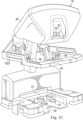
- FIG. 1A an example robotic system is shown.
- a computer-aided, robotic medical system that may be teleoperated and used in, for example, medical procedures including diagnostic, therapeutic, or surgical procedures, is generally indicated by the reference numeral 10.
- the teleoperational systems of this disclosure are under the teleoperational control of an operator.
- manipulators or other parts of a robotic system may be controlled directly through manual interaction with the manipulators (or the other parts) themselves.
- "teleoperated manipulators” as used in this application include manipulators that can be controlled only through teleoperation, and manipulators that can be controlled through teleoperation and through direct manual control.
- a non-teleoperational or robotic medical system may be under the partial control of a computer programmed to perform the procedure or sub-procedure.
- a fully automated medical system under the full control of a computer programmed to perform the procedure or sub-procedure, may be used to perform procedures or sub-procedures.
- the robotic medical system 10 generally includes a manipulator assembly 12 mounted to or near an operating table O on which a patient P is positioned.
- the manipulator assemblies described herein often include one or more robotic manipulators and tools mounted thereon, although the term "manipulator assembly" also encompasses the manipulator without the tool mounted thereon.
- the manipulator assembly 12 may be referred to as a patient side cart in this example, since it comprises a cart and is designed to be used next to a patient.
- a medical tool 14 also referred to as a tool 14
- a medical tool 15 are operably coupled to the manipulator assembly 12.
- the medical tool 15 includes an imaging device, and may also be referred to as the imaging tool 15.
- the imaging tool 15 may comprise an endoscopic imaging system using optical imaging technology, or comprise another type of imaging system using other technology (e.g. ultrasonic, fluoroscopic, etc.).
- An operator input system 16 allows an operator such as a surgeon or other type of clinician S to view images of or representing the procedure site and to control the operation of the medical tool 14 and/or the imaging tool 15.
- the operator input system 16 for the robotic medical system 10 may be "mechanically grounded” by being connected to a base with linkages such as to an operator's console, or it may be “mechanically ungrounded” and not be thus connected. As shown in FIG. 1A , the operator input system 16 is connected to an operator's console 38 that is usually located in the same room as operating table O during a surgical procedure. It should be understood, however, that the operator S can be located in a different room or a completely different building from the patient P.
- the operator input system 16 generally includes one or more control device(s) for controlling the medical tool 14.
- the operator input system 16 is also referred to herein as "master manipulators,” “master control devices,” “master input devices,” and “input devices.”
- the control device(s) may include one or more of any number of a variety of input devices, such as hand grips, joysticks, trackballs, data gloves, trigger-guns, foot pedals, hand-operated controllers, voice recognition devices, touch screens, body motion or presence sensors, and the like.
- the control device(s) will be provided with the same degrees of freedom as the medical tools of the robotic assembly to provide the operator with telepresence; that is, the operator is provided with the perception that the control device(s) are integral with the tools so that the operator has a sense of directly controlling tools as if present at the procedure site.
- Other motorized drive systems may move the distal end of the medical instrument in multiple degrees of freedom, which may include three degrees of linear motion (e.g., linear motion along the X, Y, Z Cartesian axes) and in three degrees of rotational motion (e.g., rotation about the X, Y, Z Cartesian axes). Additionally, the motors can be used to actuate an articulable end effector of the tool for grasping tissue in the jaws of a biopsy device or the like.
- the medical tools 14 may include end effectors having a single working member such as a scalpel, a blunt blade, a needle, an imaging sensor, an optical fiber, an electrode, etc.
- Other end effectors may include multiple working members, and examples include forceps, graspers, scissors, clip appliers, staplers, bipolar electrocautery instruments, etc.
- the medical tool 28 and the surgical tools 30a-c can be positioned and manipulated through incisions in, or natural orifices of, the patient so that a kinematic remote center is maintained at the incisions or natural orifices.
- Images of the work site can include images of the distal ends of the surgical tools 30a-c when they are positioned within the field-of-view of the imaging device of the medical tool 28.
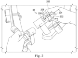
- input control devices 36 may include one or more of any number of a variety of input devices such as grip inputs 206 and trigger switches 208.
- a master reference frame 202 associated with the input control device 36 denoted as m1 is provided.
- the Z-axis of the master reference frame 202 is parallel to an axis of symmetry 204 of the input control device 36.
- the X and Y axes of the master reference frame 202 extend perpendicularly from the axis of symmetry 204.
- the operator reference frame 302 may correspond with any appropriate portion of the operating environment, or with the operating environment itself.
- the origin, the orientation, or both origin and orientation of the operator reference frame 302 may correspond with a part of the operator S, or a part of the robotic system.
- the operator reference frame 302 may have an origin based on the position of, and an orientation based on the orientation of, part or all of, the operator S (including, for example, the head, the torso, the entire body, or another body part of the operator).
- the operator reference frame 302 may be based on a position of something held or otherwise attached to the operator, such as a head-mounted display, one or more hand-held input device, tracking markers or sensors attached to the operator S, etc.
- the operator reference frame 302 may coincide with a display screen used to display images of the work space, a sensor system used to detect the operator S (or items attached to the operator S). Such a sensor system may be placed near the operator S or the display screen, such as on top of, below, or next to the operator or display screen.
- the operator reference frame 302 corresponds to a location and orientation of a viewer of the system through which the operator looks through to the work site.
- the operator reference frame 302 is defined with both origin and orientation corresponding with the usual or expected position and orientation the operator S's eyes, when the operator S is viewing the surgical site on a display 308 of an operator's console 38. As such, this operator reference frame 302 is sometimes referred to as an eye reference frame.
- the Z-axis of the operator reference frame 302 extends along a line of sight 306 of the operator S, when viewing the surgical site through the display 308.
- the X and Y axes of the operator reference frame 302 extend perpendicularly from the Z-axis at an origin 304 of the operator reference frame 302.
- a robotic system e.g., a robotic medical system 10 of FIG. 1A
- the manipulator assembly 402 includes a base 406, a structure support 408, and a manipulator 410.
- an imaging tool 15 is mounted on the manipulator 410 and thus the manipulator assembly 402 can be considered to further include the mounted imaging tool 15.
- the imaging tool 15 includes a shaft 412 and an imaging device 414.
- the imaging device 414 may include for example an optical imager, an ultrasonic imager, an electromagnetic imager such as a fluoroscopic imager, a thermal imager, a thermoacoustic imager, and any other suitable imagers.
- the imaging device 414 has a field of view 416.
- the base 406 has a reference frame 418, which is also referred to as a camera base reference frame 418 and denoted as b1.
- the imaging device 414 has a reference frame 420, which is also referred to as a camera reference frame 420 and denoted as c.
- a transformation from the base reference frame 418 to the camera reference frame 420 is denoted as b 1 R c , which may be determined based on the forward kinematics of the manipulator assembly 402.
- the relative positions and orientations of the bases 406 and 422 are unknown. As such, the transformation b 1 R b 2 from the camera base reference frame 418 b1 to the tool base reference frame 434 b2 is unknown.
- the bases 406 and 422 are coplanar or on parallel planes, such as located on a horizontal and even surface (herein called plane 438).
- Such an unknown alignment relationship between the bases 406 and 422 may make intuitive control of a slave tool/end effector by a master control device difficult.
- a master control device and its slave tool/end effector also referred to as a master-tool alignment
- a spatial alignment between the master control device and the tool/end effector is needed.
- Such a spatial alignment provides a reasonably accurate relationship between the operator's perceived motion of the master control device (e.g., a proprioceptive sense) and the operator's perceived resulting motion of the tool including the shaft and the end effector (e.g., a visual sense).
- the operator moves a hand grasping a master control device to the left, the operator expects to perceive the associated slave tool/end effector to move to the left also. If the perceived spatial motions match, then the operator can easily control the slave's movement by moving the master control device. But if the perceived spatial motions do not match (e.g., a master control device movement to the left results in a slave movement up and to the right), then it is difficult for the operator to control the slave's movement by moving the master control device.
- the kinematic relationship between the camera base reference frame 418 and camera reference frame 420 may be determined using known kinematic calculations.
- relative orientations of the camera base reference frame 418 and the tool base reference frame 434 without knowledge of relative positions of these reference frames may be sufficient to enable intuitively correct tool operations controlled by an operator using a master control device. That is, even without information about the relative positions of the camera base reference frame 418 and the tool base reference frame 434, translations and rotations at the master control device may result in corresponding translations and rotations that feel intuitively correct at the tool 14 because the relative orientations are consistent with a first alignment relationship (e.g., e 1 R m 1 ) between the eye reference frame 302 and master reference frame 202 and a second alignment relationship (e.g., c R ena effector ) between the camera reference frame 420 and an end effector reference frame associated with the end effector 432.
- the operator-guided registration process may determine a transformation b 1 R b 2 involving only rotational parameters ⁇ , ⁇ , and ⁇ (without any translational parameters) for master-tool control with intuitively correct tool
- sin( ⁇ ) and cos( ⁇ ) are computed using any two of the three equations (7), (8), and (9) (e.g., equations (7) and (8), equations (8) and (9), or equations (7) and (9)).
- the bearing angle ⁇ may be determined using an inverse tangent function based on sin( ⁇ ) and cos( ⁇ ).
- the denominators of those equations may not be zero. In other words, in some embodiments where denominators of equations (10) and (11) are equal to zero, the bearing angle ⁇ may not be computed.
- sin( ⁇ ) and cos( ⁇ ) may be computed using three equations (7), (8), and (9).
- an alignment is considered to be achieved when an amount of misalignment is within a tolerance determined based on the needed motion accuracy.
- an operator may perform an alignment step to move the master control device, and provide an indication to the control system after the operator determines that the master control device is aligned with the alignment target of the manipulator assembly 404 shown in a display of the operator's control console. As shown in FIGS.
- the operator-guided registration process may map a single rotational parameter for a base transformation between the camera base reference frame and the tool base reference frame.
- the alignment target is a shaft 428 of the tool 14.
- the operator-guided registration process may map multiple parameters (translational and/or rotational parameters) for a base transformation between the camera base reference frame and the tool base reference frame.
- the alignment target includes the shaft 428, the wrist 430, and the end effector 432 of the tool 14. It is noted that while in FIGS. 5 through 16 specific examples are used to describe the alignment target, the alignment target may include any portion of the manipulator assembly 404.
- Such presentation properties of the maker may be used to indicate a direction (e.g., front or back) and an orientation (a roll angle representing a rotation around the X-axis).
- the marker e.g., a cylinder
- the marker may not indicate a direction or an orientation.
- the marker may use various presentation properties, e.g., a particular shape (e.g., a cone), a color change, a pattern, a symbol, a text, and/or a combination thereof to indicate a direction and/or an orientation associated with the marker.
- the operator-guided registration process is configured to map a single rotational parameter (e.g., a bearing angle ⁇ around Z-axis) for a base transformation (e.g., b 1 Rb 2 ) between the camera base reference frame and the tool base reference frame.
- a single-parameter marker associated with that single rotational parameter may be used to assist the operator S in the alignment step.
- the single-parameter marker may have a shape (e.g., a line, a cone, a cylinder) with an axis (e.g., an axis of symmetry) associated with that single parameter to be mapped.
- the operator S may align the single-parameter marker with an alignment target of the manipulator assembly 404 by moving the master control device, such that the axis of the single-parameter marker is aligned with the corresponding axis of the alignment target.
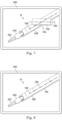
- a display 500 (e.g., a display 308 of FIG. 3B ) before the operator performs an alignment step of the operator-guided registration process.
- the display 500 shows a portion of the tool 14 that is in the field of view 416 of the imaging device 414.
- the portion of the tool 14 includes a portion of the shaft 428, the wrist 430, and the end effector 432.
- the display 500 also includes a cone marker 502 having a first position 508.
- the marker 502 has an axis 504 corresponding to the Z-axis of the master reference frame 202 of the master control device.
- the operator S may be instructed to move the master control device to change the position and/or orientation of the marker 502 in the display 500, such that the marker 502 is aligned with an alignment target (e.g., the shaft 428) in the display 500.
- the marker 502 is aligned with the shaft 428 in the display 500 after the axis 504 of the marker 502 is parallel to an axis 506 of symmetry of the shaft 428 in the display 500.
- the instruction may be provided to the operator S using a text message on the display 500 or an audio message provided through a speaker or a headphone worn by the operator S, such that the operator S may receive the instruction while viewing the display 500.
- the instruction may include an identification of the alignment target (e.g., a shaft 428, an end effector 432, an axis of symmetry of the shaft 428, an axis of symmetry of the end effector 432) to the operator S.
- the alignment target e.g., a shaft 428, an end effector 432, an axis of symmetry of the shaft 428, an axis of symmetry of the end effector 432
- an instruction is provided to the operator S identifying the shaft 428 as the alignment target.
- the position of the marker 502 is moved so that its axis 504 is collinear with an axis 506 of symmetry of the shaft 428.
- the marker 502 of FIG. 6 may remain at the same position as that of FIG. 5 but has a different orientation such that its axis 504 is parallel to the axis 506 of symmetry of the shaft 428.
- alignment along the Z-axes of the master reference frame 202 and the shaft reference frame 436 is achieved.
- the operator S determines that the marker 502 is aligned with the shaft 428 in the display 500 of FIG. 6 , the operator S provides an indication using the master control device (e.g., using a hand grip, a button, a slider, a foot pedal, a voice recognition device, and the like) to the control system, indicating that the alignment step of the operator-guided registration process is completed.
- the control system may perform a registration step to compute the parameter to be mapped (e.g. bearing angle ⁇ around Z-axis) according to equations (10) and (11) or (12).
- the control system may then compute the base transformations b 1 R b 2 using the bearing angle ⁇ according to equation (6) as discussed above.
- a marker may be presented on the display based on the alignment target, such that the operator may provide a more accurate alignment between the master control device and the alignment target.
- the marker may have a shape, color, size, translucency, any other presentation property, and/or a combination thereof that are determined based on the alignment target.
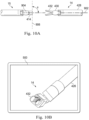
- a display 500 includes a portion of the tool 14 in the field of view 416 of the imaging device 414 before an operator performs an alignment step.
- the portion of the tool 14 includes a shaft 428, a wrist 430 coupled to the distal end of the shaft 428, and an end effector 432 coupled to the wrist 430.
- the shaft 428 has an axis 708 corresponding to the Z-axis of the shaft reference frame 436.
- the display 500 also includes a marker 702 at a position 704.
- the marker 702 has an axis 706 corresponding to the Z-axis of the master reference frame 202.
- the operator may achieve better alignment accuracy.
- the operator-guided registration process may include two steps, an alignment step and a registration step.
- Each of the alignment step and registration step has its own best and worst cases regarding the positions and orientations of the tool 14 and/or the imaging device 414.
- FIGS. 9A through 12 illustrate the best and worst cases in alignment error sensitivity in the alignment step.
- FIGS. 13 and 14 illustrate the best and worst cases in the registration step.
- the manipulator assemblies 402 and/or 404 may be configured (e.g., manually by an operator or controlled using a master control device) such that they do not have configurations corresponding to the worst cases.
- the control system may disable its operator-guided registration mode for performing the operator-guided registration process after it determines that the manipulator assemblies 402 and 404 have worst case configurations for the alignment and/or registration step, and enable the operator-guided registration mode after the manipulator assemblies 402 and 404 are moved out of the worst case configurations.
- the alignment target is the shaft 428 of the tool 14.
- the alignment target may be any portion of the manipulator assembly 404 controlling the tool 14.
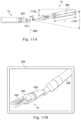
- FIG. 9A illustrates the relative positions and orientations of the shaft 428 and the imaging device 414.
- the shaft 428 of the tool 14 has an alignment target axis 902.
- the imaging tool 15 includes an imaging device 414 having an optical axis 904. The tool 14 and the imaging tool 15 are positioned such that the optical axis 904 is perpendicular to the alignment target axis 902.
- the shaft 428 of the tool 14 lies entirely in a plane that is perpendicular to the optical axis 904 of the imaging device 414 and parallel to an optical plane 906 of the imaging device 414.
- the entire length L of the shaft 428 is projected on the optical plane 906.
- FIG. 9B illustrates a display 500 including an image of the tool 14 captured by the imaging tool 15 of FIG. 9A .
- FIG. 9B because the entire length L of the shaft 428 is projected on the optical plane 906, it is the easiest to orient a marker and align the marker to the alignment target axis 902 shown in the display 500.
- such a configuration of relative positions of the tool 14 and the imaging tool 15 as shown in FIG. 9A is associated with the best alignment error sensitivity.
- the shaft 428 of the tool 14 has an alignment target axis 902.
- the imaging tool 15 includes an imaging device 414 having an optical axis 904.
- the tool 14 and the imaging tool 15 are positioned such that the optical axis 904 is parallel to the alignment target axis 902. In other words, the axis of the shaft 428 of the tool 14 lies entirely in a plane parallel to the optical axis 904 of the imaging device 414.
- a threshold out-of-plane angle ⁇ 1 (e.g., 75 degrees) is provided indicating that at the threshold out-of-plane angle ⁇ 1, it becomes difficult for the operator S to align a marker with the shaft 428.
- An error region 1104 may be identified.
- a swivel angle cone may be identified as an error region 1104 where the out-of-plane angle ⁇ is between the out-of-plane angle ⁇ 1 and 90 degrees.
- Such an error region may identify the bounds of the position/orientation of the shaft 428, where it is difficult for the operator S to align a marker with the shaft 428, or for the system to achieve sufficiently accurate registration given a particular operator-specified alignment.
- the imaging device 414 and the shaft 428 may be configured (e.g., manually by an operator or controlled using a master control device) such that the shaft 428 is not located in the error region.
- a control system may disable its operator-guided registration mode for performing the operator-guided registration mode after determining that the shaft 428 is in the error region.
- the control system may provide an error region message to the operator notifying the operator of such worst case configuration.
- the control system may enable its operator-guided registration mode after determining that the shaft 428 is out of the error region.
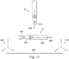
- FIGS. 13 and 14 illustrated therein are the best and worst case configurations for the registration step of the operator-guided registration process, where the registration step uses alignment information provided by the alignment step of the operator-guided registration process.
- FIG. 13 illustrates the best case configuration for the registration step of the operator-guided registration process, which provides the most alignment information for registration.
- FIG. 14 illustrates the worst case configuration for the registration step of the operator-guided registration process, which provides the least alignment information for registration.
- an angle mismatch between the marker and the alignment target axis 902 (e.g., an angle between the Z-axes of the master control device frame and the shaft frame) is identical to the relative bearing angle ⁇ between camera base reference frame 418 and the tool base reference frame 434.
- the Z-axes of the camera base reference frame 418 and the tool base reference frame 434 are vertical.
- the imaging device 414 of the imaging tool 15 has a position/orientation such that its optical axis 904 is perpendicular to the Z-axes of the camera base reference frame 418 and the tool base reference frame 434.
- Such a configuration provides no alignment information content for registration (e.g., relative bearing angle ⁇ between the bases 406 and 422 of FIG. 4 ).
- even the best alignment of the marker and the shaft 428 during the alignment step may not provide any relevant information regarding the content for registration (e.g., relative bearing angle ⁇ between the bases 406 and 422).
- changing the position of the shaft 428 may not improve the relevant information content for registration.
- the imaging device 414 is moved to a position/orientation where its optical axis is not perpendicular to any of the associated X, Y, and Z-axes.
- the marker 1502 When the marker 1502 is in a virtual representation of a tool, the marker 1502 is also referred to as a virtual tool 1502 herein.
- the virtual tool 1502 and its position, orientation, and size as shown in the display 500 may be determined by the pose of the master control device and the alignment relationship between the master control device and the display 500.
- the virtual tool 1502 is manipulatable at each joint (e.g., at the virtual wrist 1506) by the master control device, so that the pose of the tool 14 may be mimicked by the virtual tool 1502 by the operator S using the master control device in the alignment step.
- the size of the virtual tool 1502 is smaller than the actual tool 14.
- the virtual tool 1502 may be represented in a number of different ways.
- the virtual tool 1502 is a semi-transparent or translucent image of the tool 14.
- the virtual tool 1502 is a wire diagram image of the tool 14.
- the virtual tool 1502 is an image that appears solid (i.e., not transparent/translucent), but such a solid virtual tool 1502 may make viewing of the actual tool 14 in the display 500 difficult.
- the operator S determines that the virtual tool 1502 is aligned with (e.g., completely overlaying) the alignment target (e.g., the tool 14) in the display 500 of FIG. 16 .
- the operator S provides an indication to the control system indicating that the alignment step of the operator-guided registration process is completed.
- the control system may compute one or more parameters (e.g., one or more of the six parameters in six total degrees of freedom in a three-dimensional space) according to equation (5).
- the transformation b 2 R target in the equation (5) is a transformation between the tool base reference frame 434 to an end effector reference frame of the end effector 432.
- a marker 1502 that is a virtual representation of the tool 14 is used for multiple-parameter (e.g., three orientation parameters and the three translation parameters between the two base reference frames) mapping
- the marker 1502 may use various visual indicators (e.g., markings, textures, colors, shapes, text) for such multiple-parameter mapping.
- the marker 1502 may include virsual indicators corresponding to particular features (e.g., flanges, indentations, protrusions) of the tool 14.
- an operator S may align the marker 1502 and the tool 14 in both positions and orientations by matching the marker 1502 with the image of the tool 14 in the display. As such, multiple-parameter mapping may be achieved.
- FIG. 17 illustrates a method 1700 for performing an operator-guided registration process.
- the method 1700 is illustrated in FIG. 17 as a set of operations or processes 1702 through 1718. Not all of the illustrated processes 1702 through 1718 may be performed in all embodiments of method 1700. Additionally, one or more processes that are not expressly illustrated in FIG. 17 may be included before, after, in between, or as part of the processes 1702 through 1718. In some embodiments, one or more of the processes may be implemented, at least in part, in the form of executable code stored on non-transitory, tangible, machine-readable media that, when run by one or more processors (e.g., the processors of a control system such as control system 20), causes the one or more processors to perform one or more of the processes.
- processors e.g., the processors of a control system such as control system 20
- the operator-guided registration process may take much less time than registration processes using computationally expensive image processing, and may be performed during a surgical operation. Furthermore, the operator-guided registration process may be performed without using additional sensors or other hardware in addition to the joint encoders in the manipulators, and may not suffer from sensor related restrictions such as line of sight, magnetic interference, etc.
- the method 1700 begins at process 1702, where a control system of a robotic medical system is switched to an operator-guided registration mode.
- the control system may determine whether there is a control loop between a master control device and a tool, and interrupt that control loop if any.
- the tool is not controlled by the master control device.
- the control system may keep the tool and/or an imaging device stationary.
- control system may disable the operator-guided registration mode and/or provide a warning message to an operator after determining that an imaging device and a tool of the robotic medical system have configurations that correspond to the worst case configurations in alignment step and/or registration step as discussed above with reference to FIGS. 9A through 14 .
- the method 1700 may proceed to process 1704, where an image of a tool captured by an imaging device of the robotic medical system is provided to an operator through a display of an operator's console.
- an image of a tool 14 is captured by an imaging device 414 of a robotic medical system.
- an image including the field of view of the imaging device 414 is provided to an operator S through a display 500 of an operator's console.
- the displayed image may include portions of the tool 14 including, for example, shaft 428, wrist 430, and end effector 432.
- the method 1700 may then proceed to process 1706, where an operator S is instructed to align the master control device with an alignment target of the tool 14 provided in the display without the assistance of a marker in the display.
- the method 1700 may proceed to process 1710, where a marker is provided to the operator S through the display 500 to assist the operator S to perform an alignment step.
- a control system may determine the type (e.g., single-parameter marker, multiple-parameter marker) of the marker based on the parameters to be determined by the operator-guided registration process.
- the single-parameter marker may have a shape (e.g., a line, a cone, a cylinder) with an axis (e.g., axis 504 of FIG. 5 , axis 706 of FIG. 7 ) associated with the single parameter to be determined.
- the operator S may align the single-parameter marker with an alignment target of the tool by moving the master control device, such that the axis of the single-parameter marker is aligned with the corresponding alignment axis of the alignment target.
- the operator-guided registration process is configured to determine multiple parameters including rotational parameters (e.g., describing rotation about the X, Y, and Z-axes) and/or translational parameters (e.g., describing displacement along the X, Y, and Z-axes) associated with the base transformation b 1 R b 2 .
- a multi-parameter marker e.g., virtual tool 1502 of FIG. 15
- the multi-parameter marker may have a shape (e.g. a virtual representation of the tool 14) associated with those multiple parameters to be determined.
- the operator S may align the multi-parameter marker with the tool such that the multi-parameter marker and the tool completely overlay in the display by moving the master control device.
- a marker of that determined marker type is shown in the display.
- the initial position and orientation of the marker on the display may be determined based on the alignment relationship between the master control device and the display and the pose of the master control device.
- the method 1700 may then proceed to process 1712, where an operator S is instructed to align the marker with an alignment target of the tool provided in the display.
- the operator S may be instructed to align the marker with an alignment target of the tool along a single axis.
- the operator S may be instructed to control the position and orientation of the marker 502 using the master control device, such that the marker 502 is aligned with the shaft 428 of the tool 14 along axes 504 and 506.
- the operator S may be instructed to control the position and orientation of marker 702 using the master control device, such that the marker 702 overlays the shaft 428 in the display 500.
- the operator S may be instructed to control the position and orientation of the virtual tool 1502 using the master control device, such that the virtual tool 1502 and the tool 14 overlay in the display 500.
- the method 1700 may then proceed to process 1714, where the control system receives, from the operator S, an alignment completion indication indicating that the master control device is aligned with the alignment target.
- the alignment completion indication may be provided by the operator S using the master control device (e.g., using a hand grip, a foot pedal, a voice recognition device, and the like).
- an operator S may provide such an alignment completion indication when the axis 504 of the marker 502 is parallel to or collinear with the shaft 428 of the tool 14 in the display 500.
- the marker 702 has a shape (e.g., a cylinder) that is the same as that of the shaft 428.
- an operator S may provide such an alignment completion indication after the marker 702 overlays with the shaft 428 of the tool 14.
- an operator S may provide such an alignment completion indication after the virtual tool 1502 (including its virtual shaft 1504, virtual wrist 1506, and virtual end effector 1508) overlays with the tool 14 (including its shaft 428, wrist 430, and end effector 432).
- the method 1700 may then proceed to process 1716, where the control system determines the base transformation b 1 R b 2 of the robotic medical system.
- a single parameter e.g., bearing angle ⁇
- the base transformation b 1 R b 2 may then be determined according to equation (6) using that single parameter.
- multiple parameters e.g., rotational parameters and translational parameters
- the base transformation b 1 R b 2 may then be determined according to equation (4) using those multiple parameters.
- the method 1700 may then proceed to process 1718, where the control system switches to a tool control mode, and reconnects the control loop between the master control device and the tool.
- the control system may control the movement of the tool relative to the camera frame in response to movement of a master control device associated with the tool.
- the control system determines an alignment relationship between the camera reference frame and the end effector reference frame using the base transformation (e.g., b 1 R b 2 determined at process 1716).
- c R b 1 and b 2 R end effector are transformations that may be determined based on the forward and inverse kinematics of the manipulator assemblies 402 and 404 respectively, and b 1 R b 2 is already determined previously at process 1718 by the operator-guided registration process.
- the control system may derive a master-tool transform in response to state variable signals provided by the imaging system, so that an image of the tool in a display appears substantially connected to the master control device.
- state variables generally indicate the Cartesian position of the field of view of the imaging device, as supplied by the manipulator supporting the imaging device.
- the control system may derive the master-tool transform using the base transformation b 1 R b 2 determined by the operator-guided registration process, such that the control system may properly control movement of the tool 14 relative to the camera frame in response to the movement of the master control device.
- the operator-guided registration process may be performed before or during an operation (e.g., a medical operation).
- the operator-guided registration process may be performed before the medical operation (e.g. during set-up) outside of the patient or inside the patient.
- the operator-guided registration process may be performed during the medical operation.
- the operator-guided registration process may be performed as a back-up and/or calibration-check registration method where another registration process (e.g., a registration process using sensors on the bases or a registration process using image processing) is the primary registration process.
- the operator-guided registration process may be used in a robotic system having manipulators on the same base to check and confirm registration of those manipulators with their respective tools.
- One or more elements in embodiments of the invention may be implemented in software to execute on a processor of a computer system such as control processing system.
- the elements of the embodiments of the invention are essentially the code segments to perform the necessary tasks.
- the program or code segments can be stored in a processor-readable storage medium or device that may have been downloaded by way of a computer data signal embodied in a carrier wave over a transmission medium or a communication link.
- the processor readable storage device may include any medium that can store information including an optical medium, semiconductor medium, and magnetic medium.
- Processor readable storage device examples include an electronic circuit; a semiconductor device, a semiconductor memory device, a read-only memory (ROM), a flash memory, an erasable programmable read-only memory (EPROM); a floppy diskette, a CD-ROM, an optical disk, a hard disk, or other storage device,
- the code segments may be downloaded via computer networks such as the Internet, Intranet, etc.
Landscapes
- Health & Medical Sciences (AREA)
- Life Sciences & Earth Sciences (AREA)
- Surgery (AREA)
- Engineering & Computer Science (AREA)
- Nuclear Medicine, Radiotherapy & Molecular Imaging (AREA)
- Heart & Thoracic Surgery (AREA)
- General Health & Medical Sciences (AREA)
- Biomedical Technology (AREA)
- Veterinary Medicine (AREA)
- Medical Informatics (AREA)
- Molecular Biology (AREA)
- Animal Behavior & Ethology (AREA)
- Public Health (AREA)
- Robotics (AREA)
- Pathology (AREA)
- Oral & Maxillofacial Surgery (AREA)
- Gynecology & Obstetrics (AREA)
- Radiology & Medical Imaging (AREA)
- Manipulator (AREA)
Claims (15)
- Ein Robotersystem (10), das Folgendes umfasst:ein Display (308), das von einem Bediener eingesehen werden kann, wobei ein Bedienerbezugsrahmen (302) relativ zu dem Display (308) oder dem Bediener, der das Display (308) einsieht, definiert ist;ein Eingabegerät (36), das von dem Bediener bewegt werden kann;eine Verarbeitungseinheit (20), die einen oder mehrere Prozessoren einschließt, wobei die Verarbeitungseinheit zu Folgendem ausgelegt ist:Darstellen, in dem Display (308), eines ersten Bilds eines ersten Werkzeugs (14, 15), das durch ein Bildgebungsgerät (15, 414) erfasst wird;Darstellen, in dem Display, eines Markers (502), der durch das Eingabegerät (36) gesteuert wird;Erhalten, von dem Bediener, einer ersten Anzeige, dass der Marker (502) mit einem Ausrichtungsziel (428, 432) ausgerichtet ist, wobei das Ausrichtungsziel (428, 432) in dem Display dargestellt wird und mit dem ersten Bild assoziiert ist; undals Reaktion auf die erste Anzeige, Bestimmen einer ersten Ausrichtungsbeziehung auf der Grundlage einer zweiten Ausrichtungsbeziehung, wobei die erste Ausrichtungsbeziehung zwischen dem Bildgebungsgerät (15, 414) und einem ersten Werkzeug (14, 15) besteht und die zweite Ausrichtungsbeziehung zwischen dem Bedienerbezugsrahmen (302) und dem Eingabegerät (36) besteht.
- Robotersystem (10) nach Anspruch 1, wobei
der Marker (502) eine synthetische Darstellung des ersten Werkzeugs (14, 15) einschließt, damit der Bediener den Marker (502) mit einem Schaft und einem Endeffektor des ersten Werkzeugs (14, 15) in dem ersten Bild überlagert. - Robotersystem (10) nach Anspruch 1, wobei
der Marker (502) eine längliche Gestalt aufweist, damit der Bediener den Marker (502) mit einem Schaft des ersten Werkzeugs (14, 15) in dem ersten Bild abstimmt. - Robotersystem (10) nach Anspruch 1, 2 oder 3, das ferner Folgendes umfasst:eine erste Basis (406) mit einem ersten Manipulator (54, 402, 404, 410, 426) zum Koppeln mit dem Bildgebungsgerät (15, 414); undeine zweite Basis (422), die physisch von der ersten Basis (406) getrennt ist, mit einem zweiten Manipulator (54, 402, 404, 410, 426) zum Koppeln mit dem ersten Werkzeug (14, 15);wobei, um die erste Ausrichtungsbeziehung zu bestimmen, die Verarbeitungseinheit zu Folgendem ausgelegt ist:Bestimmen einer Basis-Ausrichtungsbeziehung zwischen der ersten Basis (406) und der zweiten Basis (422) unter Verwendung der zweiten Ausrichtungsbeziehung zwischen dem Bedienerbezugsrahmen (302) und dem Eingabegerät (36); undBestimmen der ersten Ausrichtungsbeziehung unter Verwendung der Basis-Ausrichtungsbeziehung.
- Robotersystem (10) nach Anspruch 4, wobei die Basis-Ausrichtungsbeziehung mit einem ersten Rotationsparameter bestimmt wird.
- Robotersystem (10) nach Anspruch 4 oder 5, wobei die Basis-Ausrichtungsbeziehung mit einem ersten Translationsparameter bestimmt wird.
- Robotersystem (10) nach einem der Ansprüche 4 bis 6, wobei die Verarbeitungseinheit, um die erste Ausrichtungsbeziehung zu bestimmen, zu Folgendem ausgelegt ist:Bestimmen einer Bildgebungsrahmentransformation von einem Bildgebungsgerät-Bezugsrahmen (42) des Bildgebungsgeräts (15, 414) zu einem ersten Basisrahmen (418), der mit der ersten Basis (406) assoziiert ist;Bestimmen einer Werkzeugrahmentransformation von einem zweiten Basisrahmen (434), der mit der zweiten Basis (422) assoziiert ist, zu einem Werkzeug-Bezugsrahmen (436), der mit dem ersten Werkzeug (14, 15) assoziiert ist; undBestimmen der ersten Ausrichtungsbeziehung unter Verwendung der Bildgebungsrahmentransformation, der Basis-Ausrichtungsbeziehung und der Werkzeugrahmentransformation.
- Robotersystem (10) nach Anspruch 7, wobeidie Bildgebungsrahmentransformation unter Verwendung von einem oder mehreren Sensoren bestimmt wird, die entlang einer ersten kinematischen Kette positioniert sind, die sich von der ersten Basis (406) zu dem Bildgebungsgerät (15, 414) erstreckt, oder wobeidie Werkzeugrahmentransformation unter Verwendung von einem oder mehreren Sensoren bestimmt wird, die entlang einer zweiten kinematischen Kette positioniert sind, die sich von der zweiten Basis (422) zu dem ersten Werkzeug (14, 15) erstreckt.
- Robotersystem (10) nach einem der Ansprüche 1 bis 8, das ferner Folgendes umfasst:eine erste Basis (58) mit einem ersten und einem zweiten Manipulator (54, 402, 404, 410, 426),wobei der erste Manipulator (54, 402, 404, 410, 426) dazu ausgelegt ist, mit dem Bildgebungsgerät (15) gekoppelt zu werden, undwobei der zweite Manipulator (54, 402, 404, 410, 426) dazu ausgelegt ist, mit dem ersten Werkzeug (14, 15) gekoppelt zu werden.
- Ein Verfahren, das Folgendes umfasst:Darstellen, in einem Display (308), das von einem Bediener eingesehen werden kann, eines ersten Bilds eines ersten Werkzeugs (14, 15), das durch ein Bildgebungsgerät (15, 414) erfasst wird;Darstellen, in dem Display (308), eines Markers (502), der von einem Eingabegerät (36) gesteuert wird, das von dem Bediener bewegt werden kann;Erhalten, von dem Bediener, einer ersten Anzeige, dass der Marker (502) mit einem Ausrichtungsziel (428, 432) ausgerichtet ist, wobei das Ausrichtungsziel (428, 432) in dem Display (308) dargestellt wird und mit dem ersten Bild assoziiert ist; undals Reaktion auf die erste Anzeige, Bestimmen einer ersten Ausrichtungsbeziehung auf der Grundlage einer zweiten Ausrichtungsbeziehung, wobei die erste Ausrichtungsbeziehung zwischen dem Bildgebungsgerät (15, 414) und dem ersten Werkzeug (14, 15) besteht und die zweite Ausrichtungsbeziehung zwischen einem Bedienerbezugsrahmen (302) und dem Eingabegerät (36) besteht,
wobei der Bedienerbezugsrahmen (302) relativ zu dem Display (308) oder dem Bediener, der das Display (308) einsieht, definiert ist. - Verfahren nach Anspruch 10, wobei:der Marker (502) eine synthetische Darstellung des ersten Werkzeugs (14, 15) einschließt, damit der Bediener den Marker (502) mit einem Schaft und einem Endeffektor des ersten Werkzeugs (14, 15) in dem ersten Bild überlagert, oder wobeider Marker (502) eine längliche Gestalt aufweist, damit der Bediener den Marker (502) mit einem Schaft des ersten Werkzeugs (14, 15) in dem ersten Bild abstimmt.
- Verfahren nach Anspruch 10 oder 11, wobei das Bestimmen der ersten Ausrichtungsbeziehung Folgendes umfasst:Bestimmen einer Basis-Ausrichtungsbeziehung zwischen einer ersten Basis und einer zweiten Basis (422) unter Verwendung der zweiten Ausrichtungsbeziehung zwischen dem Bedienerbezugsrahmen (302) und dem Eingabegerät (36),wobei die erste Basis (406) einen ersten Manipulator (54, 402, 404, 410, 426) zum Koppeln mit dem Bildgebungsgerät (15, 414) aufweist,wobei die zweite Basis (422) physisch von der ersten Basis getrennt ist und einen zweiten Manipulator (54, 410, 426) zum Koppeln mit dem ersten Werkzeug (14, 15) aufweist undwobei die Basis-Ausrichtungsbeziehung mit einem ersten Rotationsparameter bestimmt wird.
- Verfahren nach Anspruch 10 oder 11, wobei das Bestimmen der ersten Ausrichtungsbeziehung Folgendes umfasst:Bestimmen einer Basis-Ausrichtungsbeziehung zwischen einer ersten Basis und einer zweiten Basis (406, 422) unter Verwendung der zweiten Ausrichtungsbeziehung zwischen dem Bedienerbezugsrahmen und dem Eingabegerät (36),wobei die erste Basis einen ersten Manipulator (54, 402, 404, 410, 426) zum Koppeln mit dem Bildgebungsgerät aufweist,wobei die zweite Basis physisch von der ersten Basis getrennt ist und einen zweiten Manipulator (54, 402, 404, 410, 426) zum Koppeln mit dem ersten Werkzeug aufweist, undwobei die Basis-Ausrichtungsbeziehung mit einem ersten Translationsparameter bestimmt wird.
- Verfahren nach einem der Ansprüche 10 bis 13, wobei das Bestimmen der ersten Ausrichtungsbeziehung Folgendes einschließt:Bestimmen einer Bildgebungsrahmentransformation von einem Bildgebungsgerät-Bezugsrahmen (420) des Bildgebungsgeräts (15, 414) zu einem ersten Basisrahmen (418), der mit der ersten Basis (406) assoziiert ist;Bestimmen einer Werkzeugrahmentransformation von einem zweiten Basisrahmen (434), der mit der zweiten Basis (422) assoziiert ist, zu einem Werkzeug-Bezugsrahmen (436), der mit dem ersten Werkzeug (14, 15) assoziiert ist; undBestimmen der ersten Ausrichtungsbeziehung unter Verwendung der Bildgebungsrahmentransformation, der Basis-Ausrichtungsbeziehung und der Werkzeugrahmentransformation.
- Ein nichtflüchtiges maschinenlesbares Medium, das eine Vielzahl von maschinenlesbaren Anweisungen umfasst, die, wenn sie von dem einen oder den mehreren Prozessoren ausgeführt werden, dazu angepasst sind, zu bewirken, dass der eine oder die mehreren Prozessoren ein Verfahren durchführen, das Folgendes umfasst:Darstellen, in einem Display (308), das von einem Bediener eingesehen werden kann, eines ersten Bilds eines ersten Werkzeugs (14, 15), das durch ein Bildgebungsgerät (15, 414) erfasst wird;Darstellen, in dem Display (308), eines Markers (502), der durch das Eingabegerät gesteuert wird, das von dem Bediener bewegt werden kann;Erhalten, von dem Bediener, einer ersten Anzeige, dass der Marker (502) mit einem Ausrichtungsziel (428, 432) ausgerichtet ist, wobei das Ausrichtungsziel (428, 432) in dem Display (308) dargestellt wird und mit dem ersten Bild assoziiert ist; undals Reaktion auf die erste Anzeige, Bestimmen einer ersten Ausrichtungsbeziehung auf der Grundlage einer zweiten Ausrichtungsbeziehung, wobei die erste Ausrichtungsbeziehung zwischen dem Bildgebungsgerät (15, 414) und dem ersten Werkzeug (14, 15) besteht und die zweite Ausrichtungsbeziehung zwischen einem Bedienerbezugsrahmen (302) und dem Eingabegerät (36) besteht,
wobei der Bedienerbezugsrahmen (302) relativ zu dem Display (308) oder dem Bediener, der das Display (308) einsieht, definiert ist.
Priority Applications (1)
| Application Number | Priority Date | Filing Date | Title |
|---|---|---|---|
| EP25150564.0A EP4512355A3 (de) | 2017-11-21 | 2018-11-19 | Systeme und verfahren zur master-/werkzeugregistrierung und steuerung für intuitive bewegung |
Applications Claiming Priority (2)
| Application Number | Priority Date | Filing Date | Title |
|---|---|---|---|
| US201762588964P | 2017-11-21 | 2017-11-21 | |
| PCT/US2018/061729 WO2019103954A1 (en) | 2017-11-21 | 2018-11-19 | Systems and methods for master/tool registration and control for intuitive motion |
Related Child Applications (1)
| Application Number | Title | Priority Date | Filing Date |
|---|---|---|---|
| EP25150564.0A Division EP4512355A3 (de) | 2017-11-21 | 2018-11-19 | Systeme und verfahren zur master-/werkzeugregistrierung und steuerung für intuitive bewegung |
Publications (3)
| Publication Number | Publication Date |
|---|---|
| EP3713508A1 EP3713508A1 (de) | 2020-09-30 |
| EP3713508A4 EP3713508A4 (de) | 2021-01-20 |
| EP3713508B1 true EP3713508B1 (de) | 2025-01-22 |
Family
ID=66631730
Family Applications (2)
| Application Number | Title | Priority Date | Filing Date |
|---|---|---|---|
| EP25150564.0A Pending EP4512355A3 (de) | 2017-11-21 | 2018-11-19 | Systeme und verfahren zur master-/werkzeugregistrierung und steuerung für intuitive bewegung |
| EP18881976.7A Active EP3713508B1 (de) | 2017-11-21 | 2018-11-19 | Systeme und verfahren zur master/werkzeug-registrierung und zur steuerung für intuitive bewegung |
Family Applications Before (1)
| Application Number | Title | Priority Date | Filing Date |
|---|---|---|---|
| EP25150564.0A Pending EP4512355A3 (de) | 2017-11-21 | 2018-11-19 | Systeme und verfahren zur master-/werkzeugregistrierung und steuerung für intuitive bewegung |
Country Status (5)
| Country | Link |
|---|---|
| US (3) | US11877816B2 (de) |
| EP (2) | EP4512355A3 (de) |
| KR (1) | KR102577474B1 (de) |
| CN (1) | CN110709024A (de) |
| WO (1) | WO2019103954A1 (de) |
Families Citing this family (29)
| Publication number | Priority date | Publication date | Assignee | Title |
|---|---|---|---|---|
| ITUB20155057A1 (it) | 2015-10-16 | 2017-04-16 | Medical Microinstruments S R L | Assieme robotico di chirurgia |
| US11534252B2 (en) | 2017-11-16 | 2022-12-27 | Intuitive Surgical Operations, Inc. | Master/slave registration and control for teleoperation |
| EP4512355A3 (de) | 2017-11-21 | 2025-06-11 | Intuitive Surgical Operations, Inc. | Systeme und verfahren zur master-/werkzeugregistrierung und steuerung für intuitive bewegung |
| US11094221B2 (en) | 2018-06-21 | 2021-08-17 | University Of Utah Research Foundation | Visual guidance system and method for posing a physical object in three dimensional space |
| CN118438439A (zh) | 2018-10-22 | 2024-08-06 | 直观外科手术操作公司 | 用于主机/工具配准和控制以进行直观运动的系统和方法 |
| WO2020185218A1 (en) * | 2019-03-12 | 2020-09-17 | Intuitive Surgical Operations, Inc. | Layered functionality for a user input mechanism in a computer-assisted surgical system |
| CN114929146A (zh) * | 2019-12-16 | 2022-08-19 | 直观外科手术操作公司 | 促进手术空间中的非机器人装置的受指导远程操作的系统 |
| US20230139402A1 (en) * | 2020-02-24 | 2023-05-04 | Intuitive Surgical Operations, Inc. | Systems and methods for registration feature integrity checking |
| CN111281649B (zh) * | 2020-03-03 | 2021-08-13 | 西安交通大学 | 一种眼科手术机器人系统及其控制方法 |
| WO2021195158A1 (en) * | 2020-03-24 | 2021-09-30 | Intuitive Surgical Operations, Inc. | Systems and methods for determining registration of robotic manipulators or associated tools and control |
| US12605211B2 (en) | 2020-03-30 | 2026-04-21 | Intuitive Surgical Operations, Inc. | Method and system for facilitating remote presentation or interaction |
| CN111449757B (zh) * | 2020-04-10 | 2022-01-11 | 京东方科技集团股份有限公司 | 远程医疗机器人、控制方法及其充电方法 |
| CN111956329B (zh) * | 2020-08-12 | 2022-04-26 | 中国科学院深圳先进技术研究院 | 一种双臂机器人标定方法、系统、终端以及存储介质 |
| US20230270511A1 (en) * | 2020-08-26 | 2023-08-31 | Mazor Robotics Ltd. | Registration of multiple robotic arms using single reference frame |
| IT202100003479A1 (it) * | 2021-02-16 | 2022-08-16 | Medical Microinstruments Inc | Metodo per avviare una teleoperazione svolta mediante un sistema robotico per teleoperazione medica o chirurgica, avente un dispositivo master meccanicamente non vincolato e movimentabile da un operatore, con controllo di sistemi di coordinate di riferimento locali |
| IT202100003419A1 (it) * | 2021-02-16 | 2022-08-16 | Medical Microinstruments Inc | Metodo per avviare una teleoperazione svolta mediante un sistema robotico per teleoperazione medica o chirurgica, avente un dispositivo master meccanicamente non vincolato e movimentabile da un operatore |
| IT202100003476A1 (it) * | 2021-02-16 | 2022-08-16 | Medical Microinstruments Inc | Metodo per rilevare, sulla base di misura o rilevazione di velocità, anomalie operative di un dispositivo master non vincolato di un sistema robotico di tipo master-slave per teleoperazione medica o chirurgica |
| WO2022181688A1 (ja) * | 2021-02-26 | 2022-09-01 | ファナック株式会社 | ロボットの設置位置測定装置、設置位置測定方法、ロボット制御装置、教示システムおよびシミュレーション装置 |
| CN113143170A (zh) * | 2021-05-28 | 2021-07-23 | 北京天星博迈迪医疗器械有限公司 | 一种内窥镜定位的方法、装置、电子设备和可读存储介质 |
| IT202100016154A1 (it) | 2021-06-21 | 2022-12-21 | Medical Microinstruments Inc | Strumento chirurgico per chirurgia robotica |
| CN113349939B (zh) * | 2021-07-12 | 2023-03-21 | 哈尔滨思哲睿智能医疗设备股份有限公司 | 被动主手式主从控制手术机器人的性能测试方法及系统 |
| JP7748263B2 (ja) * | 2021-11-30 | 2025-10-02 | 川崎重工業株式会社 | 手術支援システム |
| CN118401351A (zh) * | 2021-12-07 | 2024-07-26 | 川崎重工业株式会社 | 示教系统、机器人系统、机器人的示教方法以及机器人的示教程序 |
| CN118369191A (zh) * | 2021-12-07 | 2024-07-19 | 川崎重工业株式会社 | 示教系统、机器人系统、机器人的示教方法以及机器人的示教程序 |
| WO2023185699A1 (zh) * | 2022-03-26 | 2023-10-05 | 深圳市精锋医疗科技股份有限公司 | 一种手术机器人和控制方法 |
| IT202200011789A1 (it) * | 2022-06-03 | 2023-12-03 | Medical Microinstruments Inc | Metodo di controllo di un sistema robotico per teleoperazione medica o chirurgica e relativo sistema robotico |
| US20240323323A1 (en) * | 2023-03-21 | 2024-09-26 | Disney Enterprises, Inc. | Telepresence system |
| CN121463927A (zh) * | 2023-07-20 | 2026-02-03 | 史密夫和内修有限公司 | 用于配准内部坐标系和外部坐标系以进行手术指导的方法和系统 |
| US20250032206A1 (en) * | 2023-07-28 | 2025-01-30 | Intuitive Surgical Operations, Inc. | Grounded virtual portal for robotic medical system |
Family Cites Families (27)
| Publication number | Priority date | Publication date | Assignee | Title |
|---|---|---|---|---|
| US6044308A (en) | 1997-06-13 | 2000-03-28 | Huissoon; Jan Paul | Method and device for robot tool frame calibration |
| US6659939B2 (en) | 1998-11-20 | 2003-12-09 | Intuitive Surgical, Inc. | Cooperative minimally invasive telesurgical system |
| US6424885B1 (en) | 1999-04-07 | 2002-07-23 | Intuitive Surgical, Inc. | Camera referenced control in a minimally invasive surgical apparatus |
| US7010390B2 (en) | 2003-07-17 | 2006-03-07 | Kuka Roboter Gmbh | Method and system for controlling robots |
| JP3733364B2 (ja) | 2003-11-18 | 2006-01-11 | ファナック株式会社 | 教示位置修正方法 |
| US8108072B2 (en) | 2007-09-30 | 2012-01-31 | Intuitive Surgical Operations, Inc. | Methods and systems for robotic instrument tool tracking with adaptive fusion of kinematics information and image information |
| US10555775B2 (en) | 2005-05-16 | 2020-02-11 | Intuitive Surgical Operations, Inc. | Methods and system for performing 3-D tool tracking by fusion of sensor and/or camera derived data during minimally invasive robotic surgery |
| US9867669B2 (en) | 2008-12-31 | 2018-01-16 | Intuitive Surgical Operations, Inc. | Configuration marker design and detection for instrument tracking |
| US20090192523A1 (en) | 2006-06-29 | 2009-07-30 | Intuitive Surgical, Inc. | Synthetic representation of a surgical instrument |
| CN102294695A (zh) | 2010-06-25 | 2011-12-28 | 鸿富锦精密工业(深圳)有限公司 | 机器人标定方法及标定系统 |
| US9259289B2 (en) * | 2011-05-13 | 2016-02-16 | Intuitive Surgical Operations, Inc. | Estimation of a position and orientation of a frame used in controlling movement of a tool |
| EP2729850A4 (de) | 2011-08-11 | 2015-07-08 | Siemens Healthcare Diagnostics | Verfahren und vorrichtung zum kalibrieren einer ausrichtung eines robotergreifers und einer kamera |
| EP2903786A2 (de) | 2012-10-05 | 2015-08-12 | Beckman Coulter, Inc. | System und verfahren für ein kamerabasierte automatische ausrichtung |
| JP6363165B2 (ja) | 2013-03-15 | 2018-07-25 | インテュイティブ サージカル オペレーションズ, インコーポレイテッド | 介入器具を追跡するための形状センサーシステム及びこのシステムの使用方法 |
| JP6010776B2 (ja) | 2013-03-19 | 2016-10-19 | パナソニックIpマネジメント株式会社 | ロボットシステムの制御方法およびロボットシステム |
| KR101527176B1 (ko) * | 2013-12-09 | 2015-06-09 | (주)미래컴퍼니 | 수술 로봇 장치 및 수술 로봇 장치의 제어 방법 |
| KR102446091B1 (ko) * | 2014-03-17 | 2022-09-22 | 인튜어티브 서지컬 오퍼레이션즈 인코포레이티드 | 촬상 장치 및 입력 컨트롤 중심복귀 시스템 및 방법 |
| DE102014214935A1 (de) | 2014-07-30 | 2016-02-04 | Siemens Aktiengesellschaft | Verfahren zum Betreiben eines medizinisch-robotischen Geräts |
| CN107072864B (zh) | 2014-10-27 | 2019-06-14 | 直观外科手术操作公司 | 用于配准到手术台的系统及方法 |
| EP4190268B1 (de) | 2015-03-17 | 2025-04-30 | Intuitive Surgical Operations, Inc. | Systeme zur onscreen-identifizierung von instrumenten in einem teleoperativen medizinischen system |
| GB201509341D0 (en) | 2015-05-29 | 2015-07-15 | Cambridge Medical Robotics Ltd | Characterising robot environments |
| WO2016201207A1 (en) | 2015-06-10 | 2016-12-15 | Intuitive Surgical Operations, Inc. | Master-to-slave orientation mapping when misaligned |
| US10758313B2 (en) * | 2015-10-07 | 2020-09-01 | Intuitive Surgical Operations, Inc. | Controlling roll for a device in a computer-assisted medical system |
| CN111566214B (zh) * | 2017-07-06 | 2024-03-08 | 日东纺绩株式会社 | 抗人IgG4单克隆抗体及利用该抗体的人IgG4测定试剂 |
| US11534252B2 (en) | 2017-11-16 | 2022-12-27 | Intuitive Surgical Operations, Inc. | Master/slave registration and control for teleoperation |
| EP4512355A3 (de) | 2017-11-21 | 2025-06-11 | Intuitive Surgical Operations, Inc. | Systeme und verfahren zur master-/werkzeugregistrierung und steuerung für intuitive bewegung |
| WO2019139949A1 (en) | 2018-01-10 | 2019-07-18 | Covidien Lp | Determining positions and conditions of tools of a robotic surgical system utilizing computer vision |
-
2018
- 2018-11-19 EP EP25150564.0A patent/EP4512355A3/de active Pending
- 2018-11-19 EP EP18881976.7A patent/EP3713508B1/de active Active
- 2018-11-19 US US16/763,552 patent/US11877816B2/en active Active
- 2018-11-19 WO PCT/US2018/061729 patent/WO2019103954A1/en not_active Ceased
- 2018-11-19 CN CN201880035658.2A patent/CN110709024A/zh active Pending
- 2018-11-19 KR KR1020197031285A patent/KR102577474B1/ko active Active
-
2023
- 2023-12-07 US US18/531,965 patent/US12232837B2/en active Active
-
2025
- 2025-01-16 US US19/026,071 patent/US20250152283A1/en active Pending
Also Published As
| Publication number | Publication date |
|---|---|
| EP3713508A1 (de) | 2020-09-30 |
| CN110709024A (zh) | 2020-01-17 |
| US20240108426A1 (en) | 2024-04-04 |
| US20250152283A1 (en) | 2025-05-15 |
| EP4512355A2 (de) | 2025-02-26 |
| US11877816B2 (en) | 2024-01-23 |
| US12232837B2 (en) | 2025-02-25 |
| US20210369365A1 (en) | 2021-12-02 |
| EP4512355A3 (de) | 2025-06-11 |
| KR102577474B1 (ko) | 2023-09-12 |
| EP3713508A4 (de) | 2021-01-20 |
| WO2019103954A1 (en) | 2019-05-31 |
| KR20200078422A (ko) | 2020-07-01 |
Similar Documents
| Publication | Publication Date | Title |
|---|---|---|
| US12232837B2 (en) | Systems and methods for master/tool registration and control for intuitive motion | |
| US12162143B2 (en) | Systems and methods for master/tool registration and control for intuitive motion | |
| US10905506B2 (en) | Systems and methods for rendering onscreen identification of instruments in a teleoperational medical system | |
| US20260076761A1 (en) | Systems and methods for switching control between multiple instrument arms | |
| EP3700457B1 (de) | Systeme und verfahren zur darstellung von erweiterter realität in einer anzeige eines teleoperationssystems | |
| EP4190268B1 (de) | Systeme zur onscreen-identifizierung von instrumenten in einem teleoperativen medizinischen system | |
| EP3592276B1 (de) | Systeme zur steuerung eines werkzeugs mit artikulierbarem distalem teil | |
| US20250367830A1 (en) | Systems and methods for determining registration of robotic manipulators or associated tools and control | |
| US12011236B2 (en) | Systems and methods for rendering alerts in a display of a teleoperational system | |
| US20240070875A1 (en) | Systems and methods for tracking objects crossing body wallfor operations associated with a computer-assisted system | |
| US12310670B2 (en) | System and method related to registration for a medical procedure | |
| EP3793468B1 (de) | Vorrichtung zur manipulation von gewebe |
Legal Events
| Date | Code | Title | Description |
|---|---|---|---|
| STAA | Information on the status of an ep patent application or granted ep patent |
Free format text: STATUS: THE INTERNATIONAL PUBLICATION HAS BEEN MADE |
|
| PUAI | Public reference made under article 153(3) epc to a published international application that has entered the european phase |
Free format text: ORIGINAL CODE: 0009012 |
|
| STAA | Information on the status of an ep patent application or granted ep patent |
Free format text: STATUS: REQUEST FOR EXAMINATION WAS MADE |
|
| 17P | Request for examination filed |
Effective date: 20200521 |
|
| AK | Designated contracting states |
Kind code of ref document: A1 Designated state(s): AL AT BE BG CH CY CZ DE DK EE ES FI FR GB GR HR HU IE IS IT LI LT LU LV MC MK MT NL NO PL PT RO RS SE SI SK SM TR |
|
| AX | Request for extension of the european patent |
Extension state: BA ME |
|
| A4 | Supplementary search report drawn up and despatched |
Effective date: 20201221 |
|
| RIC1 | Information provided on ipc code assigned before grant |
Ipc: A61B 90/00 20160101ALI20201215BHEP Ipc: A61B 34/20 20160101ALI20201215BHEP Ipc: A61B 34/00 20160101ALI20201215BHEP Ipc: A61B 34/35 20160101AFI20201215BHEP Ipc: A61B 34/37 20160101ALI20201215BHEP |
|
| DAV | Request for validation of the european patent (deleted) | ||
| DAX | Request for extension of the european patent (deleted) | ||
| P01 | Opt-out of the competence of the unified patent court (upc) registered |
Effective date: 20230510 |
|
| GRAP | Despatch of communication of intention to grant a patent |
Free format text: ORIGINAL CODE: EPIDOSNIGR1 |
|
| STAA | Information on the status of an ep patent application or granted ep patent |
Free format text: STATUS: GRANT OF PATENT IS INTENDED |
|
| INTG | Intention to grant announced |
Effective date: 20240821 |
|
| GRAS | Grant fee paid |
Free format text: ORIGINAL CODE: EPIDOSNIGR3 |
|
| GRAA | (expected) grant |
Free format text: ORIGINAL CODE: 0009210 |
|
| STAA | Information on the status of an ep patent application or granted ep patent |
Free format text: STATUS: THE PATENT HAS BEEN GRANTED |
|
| AK | Designated contracting states |
Kind code of ref document: B1 Designated state(s): AL AT BE BG CH CY CZ DE DK EE ES FI FR GB GR HR HU IE IS IT LI LT LU LV MC MK MT NL NO PL PT RO RS SE SI SK SM TR |
|
| REG | Reference to a national code |
Ref country code: GB Ref legal event code: FG4D |
|
| REG | Reference to a national code |
Ref country code: CH Ref legal event code: EP |
|
| REG | Reference to a national code |
Ref country code: IE Ref legal event code: FG4D |
|
| REG | Reference to a national code |
Ref country code: DE Ref legal event code: R096 Ref document number: 602018078755 Country of ref document: DE |
|
| REG | Reference to a national code |
Ref country code: NL Ref legal event code: MP Effective date: 20250122 |
|
| PG25 | Lapsed in a contracting state [announced via postgrant information from national office to epo] |
Ref country code: NL Free format text: LAPSE BECAUSE OF FAILURE TO SUBMIT A TRANSLATION OF THE DESCRIPTION OR TO PAY THE FEE WITHIN THE PRESCRIBED TIME-LIMIT Effective date: 20250122 |
|
| PG25 | Lapsed in a contracting state [announced via postgrant information from national office to epo] |
Ref country code: RS Free format text: LAPSE BECAUSE OF FAILURE TO SUBMIT A TRANSLATION OF THE DESCRIPTION OR TO PAY THE FEE WITHIN THE PRESCRIBED TIME-LIMIT Effective date: 20250422 |
|
| PG25 | Lapsed in a contracting state [announced via postgrant information from national office to epo] |
Ref country code: FI Free format text: LAPSE BECAUSE OF FAILURE TO SUBMIT A TRANSLATION OF THE DESCRIPTION OR TO PAY THE FEE WITHIN THE PRESCRIBED TIME-LIMIT Effective date: 20250122 |
|
| PG25 | Lapsed in a contracting state [announced via postgrant information from national office to epo] |
Ref country code: PL Free format text: LAPSE BECAUSE OF FAILURE TO SUBMIT A TRANSLATION OF THE DESCRIPTION OR TO PAY THE FEE WITHIN THE PRESCRIBED TIME-LIMIT Effective date: 20250122 |
|
| PG25 | Lapsed in a contracting state [announced via postgrant information from national office to epo] |
Ref country code: ES Free format text: LAPSE BECAUSE OF FAILURE TO SUBMIT A TRANSLATION OF THE DESCRIPTION OR TO PAY THE FEE WITHIN THE PRESCRIBED TIME-LIMIT Effective date: 20250122 |
|
| REG | Reference to a national code |
Ref country code: LT Ref legal event code: MG9D |
|
| PG25 | Lapsed in a contracting state [announced via postgrant information from national office to epo] |
Ref country code: IS Free format text: LAPSE BECAUSE OF FAILURE TO SUBMIT A TRANSLATION OF THE DESCRIPTION OR TO PAY THE FEE WITHIN THE PRESCRIBED TIME-LIMIT Effective date: 20250522 Ref country code: NO Free format text: LAPSE BECAUSE OF FAILURE TO SUBMIT A TRANSLATION OF THE DESCRIPTION OR TO PAY THE FEE WITHIN THE PRESCRIBED TIME-LIMIT Effective date: 20250422 |
|
| REG | Reference to a national code |
Ref country code: AT Ref legal event code: MK05 Ref document number: 1760885 Country of ref document: AT Kind code of ref document: T Effective date: 20250122 |
|
| PG25 | Lapsed in a contracting state [announced via postgrant information from national office to epo] |
Ref country code: HR Free format text: LAPSE BECAUSE OF FAILURE TO SUBMIT A TRANSLATION OF THE DESCRIPTION OR TO PAY THE FEE WITHIN THE PRESCRIBED TIME-LIMIT Effective date: 20250122 |
|
| PG25 | Lapsed in a contracting state [announced via postgrant information from national office to epo] |
Ref country code: LV Free format text: LAPSE BECAUSE OF FAILURE TO SUBMIT A TRANSLATION OF THE DESCRIPTION OR TO PAY THE FEE WITHIN THE PRESCRIBED TIME-LIMIT Effective date: 20250122 Ref country code: PT Free format text: LAPSE BECAUSE OF FAILURE TO SUBMIT A TRANSLATION OF THE DESCRIPTION OR TO PAY THE FEE WITHIN THE PRESCRIBED TIME-LIMIT Effective date: 20250522 |
|
| PG25 | Lapsed in a contracting state [announced via postgrant information from national office to epo] |
Ref country code: BG Free format text: LAPSE BECAUSE OF FAILURE TO SUBMIT A TRANSLATION OF THE DESCRIPTION OR TO PAY THE FEE WITHIN THE PRESCRIBED TIME-LIMIT Effective date: 20250122 Ref country code: GR Free format text: LAPSE BECAUSE OF FAILURE TO SUBMIT A TRANSLATION OF THE DESCRIPTION OR TO PAY THE FEE WITHIN THE PRESCRIBED TIME-LIMIT Effective date: 20250423 |
|
| PG25 | Lapsed in a contracting state [announced via postgrant information from national office to epo] |
Ref country code: AT Free format text: LAPSE BECAUSE OF FAILURE TO SUBMIT A TRANSLATION OF THE DESCRIPTION OR TO PAY THE FEE WITHIN THE PRESCRIBED TIME-LIMIT Effective date: 20250122 |
|
| PG25 | Lapsed in a contracting state [announced via postgrant information from national office to epo] |
Ref country code: SE Free format text: LAPSE BECAUSE OF FAILURE TO SUBMIT A TRANSLATION OF THE DESCRIPTION OR TO PAY THE FEE WITHIN THE PRESCRIBED TIME-LIMIT Effective date: 20250122 |
|
| PG25 | Lapsed in a contracting state [announced via postgrant information from national office to epo] |
Ref country code: SM Free format text: LAPSE BECAUSE OF FAILURE TO SUBMIT A TRANSLATION OF THE DESCRIPTION OR TO PAY THE FEE WITHIN THE PRESCRIBED TIME-LIMIT Effective date: 20250122 |
|
| PG25 | Lapsed in a contracting state [announced via postgrant information from national office to epo] |
Ref country code: DK Free format text: LAPSE BECAUSE OF FAILURE TO SUBMIT A TRANSLATION OF THE DESCRIPTION OR TO PAY THE FEE WITHIN THE PRESCRIBED TIME-LIMIT Effective date: 20250122 |
|
| PG25 | Lapsed in a contracting state [announced via postgrant information from national office to epo] |
Ref country code: IT Free format text: LAPSE BECAUSE OF FAILURE TO SUBMIT A TRANSLATION OF THE DESCRIPTION OR TO PAY THE FEE WITHIN THE PRESCRIBED TIME-LIMIT Effective date: 20250122 |
|
| PG25 | Lapsed in a contracting state [announced via postgrant information from national office to epo] |
Ref country code: EE Free format text: LAPSE BECAUSE OF FAILURE TO SUBMIT A TRANSLATION OF THE DESCRIPTION OR TO PAY THE FEE WITHIN THE PRESCRIBED TIME-LIMIT Effective date: 20250122 Ref country code: CZ Free format text: LAPSE BECAUSE OF FAILURE TO SUBMIT A TRANSLATION OF THE DESCRIPTION OR TO PAY THE FEE WITHIN THE PRESCRIBED TIME-LIMIT Effective date: 20250122 |
|
| REG | Reference to a national code |
Ref country code: DE Ref legal event code: R097 Ref document number: 602018078755 Country of ref document: DE |
|
| PG25 | Lapsed in a contracting state [announced via postgrant information from national office to epo] |
Ref country code: RO Free format text: LAPSE BECAUSE OF FAILURE TO SUBMIT A TRANSLATION OF THE DESCRIPTION OR TO PAY THE FEE WITHIN THE PRESCRIBED TIME-LIMIT Effective date: 20250122 |
|
| PG25 | Lapsed in a contracting state [announced via postgrant information from national office to epo] |
Ref country code: SK Free format text: LAPSE BECAUSE OF FAILURE TO SUBMIT A TRANSLATION OF THE DESCRIPTION OR TO PAY THE FEE WITHIN THE PRESCRIBED TIME-LIMIT Effective date: 20250122 |
|
| PLBE | No opposition filed within time limit |
Free format text: ORIGINAL CODE: 0009261 |
|
| STAA | Information on the status of an ep patent application or granted ep patent |
Free format text: STATUS: NO OPPOSITION FILED WITHIN TIME LIMIT |
|
| 26N | No opposition filed |
Effective date: 20251023 |
|
| PGFP | Annual fee paid to national office [announced via postgrant information from national office to epo] |
Ref country code: DE Payment date: 20251126 Year of fee payment: 8 |
|
| PGFP | Annual fee paid to national office [announced via postgrant information from national office to epo] |
Ref country code: GB Payment date: 20251125 Year of fee payment: 8 |
|
| PGFP | Annual fee paid to national office [announced via postgrant information from national office to epo] |
Ref country code: FR Payment date: 20251125 Year of fee payment: 8 |