EP3713488B1 - Implantable glucose monitor - Google Patents
Implantable glucose monitor Download PDFInfo
- Publication number
- EP3713488B1 EP3713488B1 EP18800650.6A EP18800650A EP3713488B1 EP 3713488 B1 EP3713488 B1 EP 3713488B1 EP 18800650 A EP18800650 A EP 18800650A EP 3713488 B1 EP3713488 B1 EP 3713488B1
- Authority
- EP
- European Patent Office
- Prior art keywords
- light
- implantable device
- housing
- electrical signal
- optical sensor
- Prior art date
- Legal status (The legal status is an assumption and is not a legal conclusion. Google has not performed a legal analysis and makes no representation as to the accuracy of the status listed.)
- Active
Links
Images

Classifications
-
- A—HUMAN NECESSITIES
- A61—MEDICAL OR VETERINARY SCIENCE; HYGIENE
- A61B—DIAGNOSIS; SURGERY; IDENTIFICATION
- A61B5/00—Measuring for diagnostic purposes; Identification of persons
- A61B5/07—Endoradiosondes
- A61B5/076—Permanent implantation
-
- A—HUMAN NECESSITIES
- A61—MEDICAL OR VETERINARY SCIENCE; HYGIENE
- A61B—DIAGNOSIS; SURGERY; IDENTIFICATION
- A61B5/00—Measuring for diagnostic purposes; Identification of persons
- A61B5/145—Measuring characteristics of blood in vivo, e.g. gas concentration or pH-value ; Measuring characteristics of body fluids or tissues, e.g. interstitial fluid or cerebral tissue
- A61B5/14532—Measuring characteristics of blood in vivo, e.g. gas concentration or pH-value ; Measuring characteristics of body fluids or tissues, e.g. interstitial fluid or cerebral tissue for measuring glucose, e.g. by tissue impedance measurement
-
- A—HUMAN NECESSITIES
- A61—MEDICAL OR VETERINARY SCIENCE; HYGIENE
- A61B—DIAGNOSIS; SURGERY; IDENTIFICATION
- A61B5/00—Measuring for diagnostic purposes; Identification of persons
- A61B5/145—Measuring characteristics of blood in vivo, e.g. gas concentration or pH-value ; Measuring characteristics of body fluids or tissues, e.g. interstitial fluid or cerebral tissue
- A61B5/1455—Measuring characteristics of blood in vivo, e.g. gas concentration or pH-value ; Measuring characteristics of body fluids or tissues, e.g. interstitial fluid or cerebral tissue using optical sensors, e.g. spectral photometrical oximeters
- A61B5/14558—Measuring characteristics of blood in vivo, e.g. gas concentration or pH-value ; Measuring characteristics of body fluids or tissues, e.g. interstitial fluid or cerebral tissue using optical sensors, e.g. spectral photometrical oximeters by polarisation
-
- A—HUMAN NECESSITIES
- A61—MEDICAL OR VETERINARY SCIENCE; HYGIENE
- A61B—DIAGNOSIS; SURGERY; IDENTIFICATION
- A61B5/00—Measuring for diagnostic purposes; Identification of persons
- A61B5/145—Measuring characteristics of blood in vivo, e.g. gas concentration or pH-value ; Measuring characteristics of body fluids or tissues, e.g. interstitial fluid or cerebral tissue
- A61B5/1455—Measuring characteristics of blood in vivo, e.g. gas concentration or pH-value ; Measuring characteristics of body fluids or tissues, e.g. interstitial fluid or cerebral tissue using optical sensors, e.g. spectral photometrical oximeters
- A61B5/1459—Measuring characteristics of blood in vivo, e.g. gas concentration or pH-value ; Measuring characteristics of body fluids or tissues, e.g. interstitial fluid or cerebral tissue using optical sensors, e.g. spectral photometrical oximeters invasive, e.g. introduced into the body by a catheter
-
- A—HUMAN NECESSITIES
- A61—MEDICAL OR VETERINARY SCIENCE; HYGIENE
- A61B—DIAGNOSIS; SURGERY; IDENTIFICATION
- A61B5/00—Measuring for diagnostic purposes; Identification of persons
- A61B5/68—Arrangements of detecting, measuring or recording means, e.g. sensors, in relation to patient
- A61B5/6846—Arrangements of detecting, measuring or recording means, e.g. sensors, in relation to patient specially adapted to be brought in contact with an internal body part, i.e. invasive
- A61B5/6847—Arrangements of detecting, measuring or recording means, e.g. sensors, in relation to patient specially adapted to be brought in contact with an internal body part, i.e. invasive mounted on an invasive device
- A61B5/6861—Capsules, e.g. for swallowing or implanting
-
- G—PHYSICS
- G01—MEASURING; TESTING
- G01N—INVESTIGATING OR ANALYSING MATERIALS BY DETERMINING THEIR CHEMICAL OR PHYSICAL PROPERTIES
- G01N33/00—Investigating or analysing materials by specific methods not covered by groups G01N1/00 - G01N31/00
- G01N33/48—Biological material, e.g. blood, urine; Haemocytometers
- G01N33/483—Physical analysis of biological material
- G01N33/487—Physical analysis of biological material of liquid biological material
- G01N33/49—Blood
-
- A—HUMAN NECESSITIES
- A61—MEDICAL OR VETERINARY SCIENCE; HYGIENE
- A61B—DIAGNOSIS; SURGERY; IDENTIFICATION
- A61B2560/00—Constructional details of operational features of apparatus; Accessories for medical measuring apparatus
- A61B2560/02—Operational features
- A61B2560/0204—Operational features of power management
- A61B2560/0214—Operational features of power management of power generation or supply
- A61B2560/0219—Operational features of power management of power generation or supply of externally powered implanted units
-
- A—HUMAN NECESSITIES
- A61—MEDICAL OR VETERINARY SCIENCE; HYGIENE
- A61B—DIAGNOSIS; SURGERY; IDENTIFICATION
- A61B2560/00—Constructional details of operational features of apparatus; Accessories for medical measuring apparatus
- A61B2560/02—Operational features
- A61B2560/0242—Operational features adapted to measure environmental factors, e.g. temperature, pollution
- A61B2560/0247—Operational features adapted to measure environmental factors, e.g. temperature, pollution for compensation or correction of the measured physiological value
- A61B2560/0252—Operational features adapted to measure environmental factors, e.g. temperature, pollution for compensation or correction of the measured physiological value using ambient temperature
Definitions
- the present disclosure relates to an implantable device for measuring the glucose concentration of a body fluid when implanted, a system comprising an implantable device, and a method for measuring glucose concentration.
- Insulin therapy often generally requires repeated blood glucose measurements to be taken from a diabetic patient.
- Diabetics with Type I diabetes may measure blood glucose 5-9 times a day, while those with gestational diabetes may take measurements up to 11 times per day.
- Known blood glucose testing methods involve collecting a blood sample from a patient using a lancet. Blood collection using a lancet may be painful and unpleasant for a diabetic, particularly if a high testing frequency is required. Repeated blood collection from a skin site may lead to the formation of scars or calluses, or increased nerve density, which in turn can make it difficult to collect blood.
- US 2010/0160749 A1 discloses an apparatus including a support configured to be implanted within a body of a subject, wherein the apparatus comprises a light source and a sensor configured to measure a parameter of fluid from the subject.
- US 6,122,536 discloses an implantable sensor for sensing in vivo the level of at least one blood constituent in mammalian vascular tissue.
- an implantable device for measuring the glucose concentration of a body fluid when implanted, the implantable device comprising: a glucose measurement unit comprising a first light source configured to emit light towards a light transmissive part of a housing of the device and a first optical sensor configured to detect light returned through the light transmissive part from the first light source, and output a first electrical signal based on the detected light; and a wireless communication module configured to wirelessly communicate with an external wireless communication device.
- An outer surface of the housing may comprise a recess, wherein the recess comprises at least part of the light transmissive part. This is advantageous in that may facilitate movement of body fluid such as blood or interstitial fluid around the implantable device, ensuring that the body fluid around the device is not stagnant, and hence providing a more accurate glucose reading.
- the outer surface of the housing may comprise one or more projections, again to facilitate movement of body fluid around the implantable device.
- the recess may be formed from one or more protrusions of the housing.
- the implantable device may further comprise at least one lens arranged to focus the light emitted from the first light source towards a point outside the housing. This allows for accurate measurement of glucose concentration within the body fluid surrounding the housing, while reducing interference from external light sources such as ambient light.
- the light emitted from the first light source is linearly polarised and emitted through the light transmissive part to a first region outside the housing.
- the first optical sensor is configured to detect linearly polarised light returned through the transmissive part from the first region outside the housing that has been optically rotated.
- the first optical sensor is further configured to output the first electrical signal based on the detected optically rotated light. This provides a simple arrangement for determining the glucose concentration in a body fluid.
- the implantable device further comprises a first linear polarizer arranged to linearly polarize the light emitted from the first light source in a first plane, a second linear polarizer arranged to linearly polarize light from the first region outside the housing in a second plane substantially orthogonal to the first plane, and a third linear polarizer arranged to linearly polarize light from the first region outside the housing in a third plane, wherein the third plane is parallel to the first plane.
- the glucose measurement unit further comprises a second optical sensor configured to detect light returned through the light transmissive part, and output a second electrical signal based on the detected light.
- the second linear polarizer is arranged such that a first part of the linearly polarized light emitted from the first light source to the first region outside the housing is incident on the second linear polarizer.
- the third linear polarizer is arranged such that a second part of the linearly polarized light emitted from the first light source to the first region outside the housing is incident on the third linear polarizer.
- the first optical sensor is arranged to detect the first part of the linearly polarized light passing from the first region outside the housing through the second linear polarizer, and the second optical sensor is arranged to detect the second part of the linearly polarized light passing from the first region outside the housing through the third linear polarizer.
- the implantable device is configured to process the first electrical signal and the second electrical signal based on a ratio of the first electrical signal and the second electrical signal to reduce or remove the effects of interference.
- the wireless communication module is configured to wirelessly transmit a signal based on the processed first and second electrical signals to the external wireless communication device. This arrangement provides a simple means for determining the glucose concentration in a body fluid, with improved interference suppression.
- the glucose measurement unit may further comprises a second light source configured to emit light through the light transmissive part to a second region outside the housing, and a second optical sensor configured to detect light returned through the transmissive part, and output a second electrical signal based on the detected light.
- the second linear polarizer may be arranged such that at least part of the linearly polarized light emitted from the first light source to the first region outside the housing is incident on the second linear polarizer.
- the fourth linear polarizer may be arranged such that at least part of the linearly polarized light emitted from the second light source to the second region outside the housing is incident on the fourth linear polarizer.
- the first optical sensor may be configured to be able to detect the at least part of the linearly polarized light emitted from the first light source, via the second linear polarizer.
- the second optical sensor may be configured to be able to detect the at least part of the linearly polarized light emitted from the second light source, via the fourth linear polarizer.
- the implantable device further comprises a temperature sensor, wherein the wireless communication module is configured to wirelessly transmit a signal based on a temperature measured by the temperature sensor to the external wireless communication device.
- a system comprising an aforementioned implantable device and an external wireless communication device, wherein the wireless communication module of the implantable device is configured to wirelessly transmit the signal based on the processed first and second electrical signals to the external wireless communication device.
- the system allows for simple and unobtrusive measurements of glucose concentration in a body fluid.
- the external wireless communication device may be a smartphone. This is a particularly simple means for wirelessly communicating with the implantable device.
- a method comprising emitting light, by a first light source of an implantable device for measuring the glucose concentration of a body fluid when implanted, towards a light transmissive part of a housing of the implantable device; detecting, by a first optical sensor of the implantable device, light returned through the transmissive part from the first light source; outputting, by the first optical sensor, a first electrical signal based on the detected light; and wirelessly transmitting, by a wireless communication module of the implantable device, a signal based on the first electrical signal to an external wireless communication device.
- An implantable device for measuring the glucose concentration of a body fluid when implanted is provided.
- a system comprising the implantable device and an external wireless communication device, and a method of measuring the glucose concentration of a body fluid using the implantable device and external wireless communication device are also provided.
- the aforementioned body fluid is a fluid within a human or animal that contains glucose, wherein the glucose concentration can be measured for insulin therapy.
- the body fluid is preferably blood, but may alternatively or additionally be interstitial fluid. It is preferable to measure the glucose concentration in the blood of a human or animal rather than the interstitial fluid because blood is generally more responsive to changes in glucose concentration than interstitial fluid.
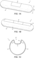
- FIG. 1 shows an implantable device 1 in accordance with some aspects of the present disclosure.
- the implantable device 1 has a housing 10, wherein other components of the implantable device 1 are located inside the housing 10.
- the housing 10 has a light transmissive part 12 which allows light of one or more wavelengths to pass through from one side of the light transmissive part 12 to another side. Light is therefore able to pass from outside the housing 10 to the inside of the housing 10 via the light transmissive part 12, and vice versa.
- a discrete region or window of the housing 10 may comprise the light transmissive part 12, as shown in Figure 1A .
- the entire housing 10 may be light transmissive.
- the light transmissive part 12 comprises a plurality of discrete regions of the housing 10, the discrete regions being separated by optically opaque parts of the housing 10.
- the housing 10 is preferably made of a biocompatible material such as glass so that the implantable device 1 may be safely implanted into a human or animal.
- a biocompatible material such as glass
- the use of glass for the housing 10 is advantageous in that glass is light transmissive, and hence the housing 10 and light transmissive part 12 may be formed from the same material, in a single process.
- the implantable device 1 is to be subcutaneously implanted within a human or animal body.
- the implantable device 1 can be implanted within a blood vessel of the human or animal, allowing for measurement of the glucose concentration in the blood of said human or animal.
- the particular body fluid being measured will be blood.
- the implantable device 1 is dimensioned to be implantable into a human blood vessel, such as an artery or vein.
- the device may have a maximum width w along one axis of around less than 5mm, preferably around less than 3mm, and more preferably around 1.35 mm to 2 mm.
- the implantable device 1 configured is to be implanted into tissue well perfused by a body fluid, such as blood.
- a body fluid such as blood
- the implantable device 1 may be implanted within the interstitial fluid of a human or animal, for example just under the skin.
- the particular body fluid being measured is the interstitial fluid.
- the implantable device 1 Once the implantable device 1 has been implanted, body fluid will come into contact with the light transmissive part 12 of the housing 10. When the implantable device 1 has been implanted in a blood vessel, blood will contact the light transmissive part 12. When the implantable device 1 has been implanted in interstitial fluid, interstitial fluid will be contacting the light transmissive part 12.
- Figure 1B shows an implantable device 1 similar to the implantable device 1 of Figure 1A , however an outer surface 11 of the housing 10 comprises a recess 14.
- Figure 1C shows a side-view of the implantable device of Figure 1B , showing a side-view of the recess 14.
- the recess 14 may comprise a first side wall 15, a second side wall 16, and a bottom surface 17.
- the recess 14 may be a groove in the outer surface 11 of the housing 10.
- the recess 14 may be a conduit through which body fluid may flow from one side of the implantable device 1 to another side of the implantable device 1.
- the conduit may extend from one side of the housing 10 to an opposing side of the housing 10.
- the recess 14 is filled with body fluid when the implantable device 1 is implanted.
- Providing a recess 14 in the housing 10 can facilitate the movement of body fluid around the implantable device 1 when the device is implanted. This may be particularly advantageous if the implantable device 1 is implanted into a blood vessel, since the recess may allow blood to flow more easily around or through the implantable device 1. As such, blood flow through the blood vessel is less obstructed by the implanted device 1.
- the housing 10 may comprise one or more protrusions (not shown) arranged on the outer surface 11.
- the one or more protrusions may be configured to hold the implantable device 1 in a fixed location within a human or animal body once implanted into said body. If the implantable device 1 is implanted into a blood vessel, the one or more protrusions may be configured to hold the implantable device 1 in a fixed location within the blood vessel by exerting pressure on the inner walls of the blood vessel.
- the light transmissive part 12 shown in Figures 1B and 1C is comprised in a discrete region of the housing 10, in this case entirely within recess 14.
- the light transmissive part 12 is not limited to this arrangement and may be located in another part of the housing 10, or may comprise the entirety of housing 10.
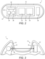
- Figure 2 is a schematic cross-section of an implantable device 1 according to embodiments of the present disclosure.
- the implantable device 1 comprises a wireless communication module 20, a glucose measurement unit 30, and a housing 10 having light transmissive part 12.
- the wireless communication module 20 is configured to wirelessly communicate with an external wireless communication device 2 (as shown in Figure 8 ), preferably using near field communication (NFC), but other forms of wireless communication may be used.
- NFC near field communication
- the wireless communication module 20 is preferably configured to wirelessly receive power from the external wireless communication 2 device by electromagnetic induction.
- the wireless communication module 20 comprises an antenna 22, an energy storage unit 24 such as a capacitor or rechargeable battery, and a control unit 26 such as an integrated circuit.
- the antenna 22 is configured to transmit and receive wireless signals, wherein transmission of wireless signals by the antenna is controlled by the control unit 26.
- the energy storage unit 24 stores electrical energy received from the external wireless communication device 2 via the antenna 22.
- the control unit 26 may comprise a memory unit (not shown) for storing instructions to be carried out by the control unit 26, and/or data related to measurements made by the glucose measurement unit 30.
- the control unit 26 may control one or more operations of the glucose measurement unit 30 described herein, and may carry out any of the method steps described herein with respect to the implantable device 1.
- the glucose measurement unit 30 comprises a light source 32 and an optical sensor 34.
- the light source 32 may comprise one or more light emitting diodes (LEDs), and is configured to emit light towards the light transmissive part 12 of the housing 10, that is, from the inside of the housing 10 towards the outside of the housing 10.
- the light source 32 is preferably powered by the energy storage unit 24 and controlled by the control unit 26.
- the optical sensor 34 also known as a light sensor, detects light by converting received light into an electrical signal. The optical sensor 34 thus outputs an electrical signal based on the detected light.
- the optical sensor 34 may comprise one or more photodetectors such as photodiodes.
- the optical sensor 34 may detect light having a specific wavelength, or a range of wavelengths.
- the optical sensor 34 may be variable. That is, the specific wavelength or range of wavelengths detected by the optical sensor 34 may be variable.
- the wavelength(s) detected by such an optical sensor 34 may be selected by changing a voltage applied to the optical sensor 34.
- the optical sensor 34 is configured to detect light returned through the light transmissive part 12 of the housing 10, and output an electrical signal based on the detected light.
- the optical sensor 34 is configured to detect light that has been emitted by the light source 32 from inside the housing 10 into the light transmissive part 12 of the housing 10 and that has returned to the inside of the housing 10 via the light transmissive part 12.
- the returned light may have travelled from the light source 32 through the light transmissive part 12 to a region outside the housing 10, before returning back through the light transmissive part 12 to the inside of the housing 10 where it is detected by the optical sensor 34.
- the returned light has travelled from the light source 32 through the light transmissive part 12, before being internally reflected at a surface of the light transmissive part 12 and returning back through the light transmissive part 12 to the inside of the housing 10, where it is detected by the optical sensor 34.
- the surface of the light transmissive part 12 at which the light is internally reflected forms part of the outer surface 11 of the housing 10, and is in contact with body fluid when the implantable device 1 is implanted.
- the output is provided using the light source 32 configured to emit light towards the light transmissive part 12 of housing 10 of the implantable device 1, and the optical sensor 34 configured to detect light returned through the transmissive part 12 from the light source 32, wherein the output is an electrical signal based on the detected light, in particular the intensity of the detected light or the amount of refraction of the detected light.
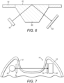
- the third linear polarizer 43 is arranged to linearly polarize light from the second region outside the housing 10 in a fourth plane, wherein the fourth plane is parallel to the third plane (i.e. rotated 0° about the optical axis).
- the fourth plane may be parallel to the first plane.
- fragment refers to a polypeptide derived from an antibody polypeptide molecule (e.g., an antibody heavy and/or light chain polypeptide) that does not comprise a full-length antibody polypeptide, but that still comprises at least a portion of a full-length antibody polypeptide that is capable of binding to an antigen.
- Antibody fragments can comprise a cleaved portion of a full length antibody polypeptide, although the term is not limited to such cleaved fragments.
- CDR complementarity-determining region
- framework region refers to amino acid sequences within the variable region of both heavy and light chain polypeptides that are not CDR sequences, and are primarily responsible for maintaining correct positioning of the CDR sequences to permit antigen binding.
- framework regions themselves typically do not directly participate in antigen binding, as is known in the art, certain residues within the framework regions of certain antibodies can directly participate in antigen binding or can affect the ability of one or more amino acids in CDRs to interact with antigen. Examples of antibodies are anti PCSK-9 mAb (e.g., Alirocumab), anti IL-6 mAb (e.g., Sarilumab), and anti IL-4 mAb (e.g., Dupilumab).
Landscapes
- Health & Medical Sciences (AREA)
- Life Sciences & Earth Sciences (AREA)
- Physics & Mathematics (AREA)
- Engineering & Computer Science (AREA)
- Biomedical Technology (AREA)
- General Health & Medical Sciences (AREA)
- Pathology (AREA)
- Biophysics (AREA)
- Molecular Biology (AREA)
- Surgery (AREA)
- Heart & Thoracic Surgery (AREA)
- Veterinary Medicine (AREA)
- Public Health (AREA)
- Animal Behavior & Ethology (AREA)
- Medical Informatics (AREA)
- Optics & Photonics (AREA)
- Spectroscopy & Molecular Physics (AREA)
- Chemical & Material Sciences (AREA)
- Hematology (AREA)
- Emergency Medicine (AREA)
- Analytical Chemistry (AREA)
- Ecology (AREA)
- Biochemistry (AREA)
- Immunology (AREA)
- Medicinal Chemistry (AREA)
- Urology & Nephrology (AREA)
- Food Science & Technology (AREA)
- General Physics & Mathematics (AREA)
- Measurement Of The Respiration, Hearing Ability, Form, And Blood Characteristics Of Living Organisms (AREA)
- Measuring And Recording Apparatus For Diagnosis (AREA)
Priority Applications (1)
| Application Number | Priority Date | Filing Date | Title |
|---|---|---|---|
| EP25157670.8A EP4545007A1 (en) | 2017-11-21 | 2018-11-15 | Implantable glucose monitor |
Applications Claiming Priority (2)
| Application Number | Priority Date | Filing Date | Title |
|---|---|---|---|
| EP17306606 | 2017-11-21 | ||
| PCT/EP2018/081303 WO2019101611A1 (en) | 2017-11-21 | 2018-11-15 | Implantable glucose monitor |
Related Child Applications (1)
| Application Number | Title | Priority Date | Filing Date |
|---|---|---|---|
| EP25157670.8A Division EP4545007A1 (en) | 2017-11-21 | 2018-11-15 | Implantable glucose monitor |
Publications (3)
| Publication Number | Publication Date |
|---|---|
| EP3713488A1 EP3713488A1 (en) | 2020-09-30 |
| EP3713488C0 EP3713488C0 (en) | 2025-03-12 |
| EP3713488B1 true EP3713488B1 (en) | 2025-03-12 |
Family
ID=60569841
Family Applications (2)
| Application Number | Title | Priority Date | Filing Date |
|---|---|---|---|
| EP18800650.6A Active EP3713488B1 (en) | 2017-11-21 | 2018-11-15 | Implantable glucose monitor |
| EP25157670.8A Pending EP4545007A1 (en) | 2017-11-21 | 2018-11-15 | Implantable glucose monitor |
Family Applications After (1)
| Application Number | Title | Priority Date | Filing Date |
|---|---|---|---|
| EP25157670.8A Pending EP4545007A1 (en) | 2017-11-21 | 2018-11-15 | Implantable glucose monitor |
Country Status (4)
| Country | Link |
|---|---|
| US (2) | US11730404B2 (enExample) |
| EP (2) | EP3713488B1 (enExample) |
| JP (3) | JP7599333B2 (enExample) |
| WO (1) | WO2019101611A1 (enExample) |
Families Citing this family (1)
| Publication number | Priority date | Publication date | Assignee | Title |
|---|---|---|---|---|
| CN120957652A (zh) * | 2023-01-31 | 2025-11-14 | 格鲁可玛特有限公司 | 高度集成的葡萄糖传感器设备 |
Family Cites Families (13)
| Publication number | Priority date | Publication date | Assignee | Title |
|---|---|---|---|---|
| US4704029A (en) | 1985-12-26 | 1987-11-03 | Research Corporation | Blood glucose monitor |
| US5995860A (en) * | 1995-07-06 | 1999-11-30 | Thomas Jefferson University | Implantable sensor and system for measurement and control of blood constituent levels |
| US6862465B2 (en) | 1997-03-04 | 2005-03-01 | Dexcom, Inc. | Device and method for determining analyte levels |
| US20020016535A1 (en) | 2000-01-28 | 2002-02-07 | Martin W. Blake | Subcutaneous glucose measurement device |
| US20070004974A1 (en) * | 2003-12-29 | 2007-01-04 | Glucon, Inc. | Glucometer comprising an implantable light source |
| US20100160749A1 (en) | 2008-12-24 | 2010-06-24 | Glusense Ltd. | Implantable optical glucose sensing |
| CN101548892B (zh) * | 2009-04-29 | 2010-12-29 | 天津市先石光学技术有限公司 | 植入式在体连续血糖监测装置 |
| US8467843B2 (en) * | 2009-11-04 | 2013-06-18 | Glumetrics, Inc. | Optical sensor configuration for ratiometric correction of blood glucose measurement |
| JP5990905B2 (ja) * | 2011-12-19 | 2016-09-14 | ソニー株式会社 | 測定装置、測定方法、プログラム及び記録媒体 |
| US9693714B2 (en) * | 2012-02-10 | 2017-07-04 | Senseonics, Incorporated | Digital ASIC sensor platform |
| US9119529B2 (en) * | 2012-10-30 | 2015-09-01 | Dexcom, Inc. | Systems and methods for dynamically and intelligently monitoring a host's glycemic condition after an alert is triggered |
| US9867540B2 (en) * | 2013-08-09 | 2018-01-16 | Senseonics, Incorporated | Co-planar, near field communication telemetry link for an analyte sensor |
| US20160310048A1 (en) * | 2013-12-05 | 2016-10-27 | Biomicro Pte. Ltd. | Implantable Biosensor |
-
2018
- 2018-11-15 EP EP18800650.6A patent/EP3713488B1/en active Active
- 2018-11-15 US US16/765,231 patent/US11730404B2/en active Active
- 2018-11-15 EP EP25157670.8A patent/EP4545007A1/en active Pending
- 2018-11-15 JP JP2020527947A patent/JP7599333B2/ja active Active
- 2018-11-15 WO PCT/EP2018/081303 patent/WO2019101611A1/en not_active Ceased
-
2023
- 2023-06-29 US US18/344,089 patent/US20230337950A1/en active Pending
- 2023-08-18 JP JP2023133217A patent/JP7731944B2/ja active Active
-
2025
- 2025-04-24 JP JP2025071983A patent/JP2025108723A/ja active Pending
Also Published As
| Publication number | Publication date |
|---|---|
| JP7599333B2 (ja) | 2024-12-13 |
| JP2023159272A (ja) | 2023-10-31 |
| US20230337950A1 (en) | 2023-10-26 |
| US20200275866A1 (en) | 2020-09-03 |
| EP3713488C0 (en) | 2025-03-12 |
| JP2025108723A (ja) | 2025-07-23 |
| EP3713488A1 (en) | 2020-09-30 |
| US11730404B2 (en) | 2023-08-22 |
| JP2021503985A (ja) | 2021-02-15 |
| JP7731944B2 (ja) | 2025-09-01 |
| EP4545007A1 (en) | 2025-04-30 |
| WO2019101611A1 (en) | 2019-05-31 |
Similar Documents
| Publication | Publication Date | Title |
|---|---|---|
| US12419548B2 (en) | Implantable glucose monitor | |
| US11504480B2 (en) | Data collection from a medicament delivery device | |
| US20200324055A1 (en) | Apparatus for detecting activation of a drug delivery device | |
| US12343512B2 (en) | Electronics for dosage sensing | |
| JP2025108723A (ja) | 埋込可能なグルコースモニタ | |
| US11400230B2 (en) | Reading device, drug delivery device and drug delivery device in combination with a reading device | |
| EP3938012A1 (en) | Apparatus for measuring medicament level | |
| EP3618894B1 (en) | Cartridge for dosage sensing | |
| EP3727515A1 (en) | Transmission of data associated with an injection device usage using passive rf modulation | |
| US20230241322A1 (en) | Improvements of an optical sensing system of a drug delivery device | |
| US20250108177A1 (en) | Electronic system, user interface member, drug delivery device and method for detecting whether a drug delivery device is, or was, exposed to fluid | |
| US20200282142A1 (en) | Bolus Calculator and Method for Calculating a Bolus | |
| HK40015310A (en) | Cartridge for dosage sensing | |
| HK40015310B (en) | Cartridge for dosage sensing |
Legal Events
| Date | Code | Title | Description |
|---|---|---|---|
| STAA | Information on the status of an ep patent application or granted ep patent |
Free format text: STATUS: UNKNOWN |
|
| STAA | Information on the status of an ep patent application or granted ep patent |
Free format text: STATUS: THE INTERNATIONAL PUBLICATION HAS BEEN MADE |
|
| PUAI | Public reference made under article 153(3) epc to a published international application that has entered the european phase |
Free format text: ORIGINAL CODE: 0009012 |
|
| STAA | Information on the status of an ep patent application or granted ep patent |
Free format text: STATUS: REQUEST FOR EXAMINATION WAS MADE |
|
| 17P | Request for examination filed |
Effective date: 20200622 |
|
| AK | Designated contracting states |
Kind code of ref document: A1 Designated state(s): AL AT BE BG CH CY CZ DE DK EE ES FI FR GB GR HR HU IE IS IT LI LT LU LV MC MK MT NL NO PL PT RO RS SE SI SK SM TR |
|
| AX | Request for extension of the european patent |
Extension state: BA ME |
|
| DAV | Request for validation of the european patent (deleted) | ||
| DAX | Request for extension of the european patent (deleted) | ||
| STAA | Information on the status of an ep patent application or granted ep patent |
Free format text: STATUS: EXAMINATION IS IN PROGRESS |
|
| 17Q | First examination report despatched |
Effective date: 20210721 |
|
| GRAP | Despatch of communication of intention to grant a patent |
Free format text: ORIGINAL CODE: EPIDOSNIGR1 |
|
| STAA | Information on the status of an ep patent application or granted ep patent |
Free format text: STATUS: GRANT OF PATENT IS INTENDED |
|
| INTG | Intention to grant announced |
Effective date: 20240903 |
|
| RAP3 | Party data changed (applicant data changed or rights of an application transferred) |
Owner name: SANOFI |
|
| GRAJ | Information related to disapproval of communication of intention to grant by the applicant or resumption of examination proceedings by the epo deleted |
Free format text: ORIGINAL CODE: EPIDOSDIGR1 |
|
| STAA | Information on the status of an ep patent application or granted ep patent |
Free format text: STATUS: EXAMINATION IS IN PROGRESS |
|
| GRAP | Despatch of communication of intention to grant a patent |
Free format text: ORIGINAL CODE: EPIDOSNIGR1 |
|
| STAA | Information on the status of an ep patent application or granted ep patent |
Free format text: STATUS: GRANT OF PATENT IS INTENDED |
|
| GRAS | Grant fee paid |
Free format text: ORIGINAL CODE: EPIDOSNIGR3 |
|
| GRAL | Information related to payment of fee for publishing/printing deleted |
Free format text: ORIGINAL CODE: EPIDOSDIGR3 |
|
| GRAS | Grant fee paid |
Free format text: ORIGINAL CODE: EPIDOSNIGR3 |
|
| GRAA | (expected) grant |
Free format text: ORIGINAL CODE: 0009210 |
|
| STAA | Information on the status of an ep patent application or granted ep patent |
Free format text: STATUS: THE PATENT HAS BEEN GRANTED |
|
| INTG | Intention to grant announced |
Effective date: 20250114 |
|
| AK | Designated contracting states |
Kind code of ref document: B1 Designated state(s): AL AT BE BG CH CY CZ DE DK EE ES FI FR GB GR HR HU IE IS IT LI LT LU LV MC MK MT NL NO PL PT RO RS SE SI SK SM TR |
|
| REG | Reference to a national code |
Ref country code: GB Ref legal event code: FG4D |
|
| REG | Reference to a national code |
Ref country code: CH Ref legal event code: EP |
|
| REG | Reference to a national code |
Ref country code: DE Ref legal event code: R096 Ref document number: 602018080073 Country of ref document: DE |
|
| REG | Reference to a national code |
Ref country code: IE Ref legal event code: FG4D |
|
| U01 | Request for unitary effect filed |
Effective date: 20250401 |
|
| U07 | Unitary effect registered |
Designated state(s): AT BE BG DE DK EE FI FR IT LT LU LV MT NL PT RO SE SI Effective date: 20250407 |
|
| PG25 | Lapsed in a contracting state [announced via postgrant information from national office to epo] |
Ref country code: RS Free format text: LAPSE BECAUSE OF FAILURE TO SUBMIT A TRANSLATION OF THE DESCRIPTION OR TO PAY THE FEE WITHIN THE PRESCRIBED TIME-LIMIT Effective date: 20250612 |
|
| PG25 | Lapsed in a contracting state [announced via postgrant information from national office to epo] |
Ref country code: ES Free format text: LAPSE BECAUSE OF FAILURE TO SUBMIT A TRANSLATION OF THE DESCRIPTION OR TO PAY THE FEE WITHIN THE PRESCRIBED TIME-LIMIT Effective date: 20250312 |
|
| PG25 | Lapsed in a contracting state [announced via postgrant information from national office to epo] |
Ref country code: NO Free format text: LAPSE BECAUSE OF FAILURE TO SUBMIT A TRANSLATION OF THE DESCRIPTION OR TO PAY THE FEE WITHIN THE PRESCRIBED TIME-LIMIT Effective date: 20250612 |
|
| PG25 | Lapsed in a contracting state [announced via postgrant information from national office to epo] |
Ref country code: HR Free format text: LAPSE BECAUSE OF FAILURE TO SUBMIT A TRANSLATION OF THE DESCRIPTION OR TO PAY THE FEE WITHIN THE PRESCRIBED TIME-LIMIT Effective date: 20250312 |
|
| PG25 | Lapsed in a contracting state [announced via postgrant information from national office to epo] |
Ref country code: GR Free format text: LAPSE BECAUSE OF FAILURE TO SUBMIT A TRANSLATION OF THE DESCRIPTION OR TO PAY THE FEE WITHIN THE PRESCRIBED TIME-LIMIT Effective date: 20250613 |
|
| PG25 | Lapsed in a contracting state [announced via postgrant information from national office to epo] |
Ref country code: SM Free format text: LAPSE BECAUSE OF FAILURE TO SUBMIT A TRANSLATION OF THE DESCRIPTION OR TO PAY THE FEE WITHIN THE PRESCRIBED TIME-LIMIT Effective date: 20250312 |
|
| PG25 | Lapsed in a contracting state [announced via postgrant information from national office to epo] |
Ref country code: PL Free format text: LAPSE BECAUSE OF FAILURE TO SUBMIT A TRANSLATION OF THE DESCRIPTION OR TO PAY THE FEE WITHIN THE PRESCRIBED TIME-LIMIT Effective date: 20250312 |
|
| PGFP | Annual fee paid to national office [announced via postgrant information from national office to epo] |
Ref country code: GB Payment date: 20250925 Year of fee payment: 8 |
|
| PG25 | Lapsed in a contracting state [announced via postgrant information from national office to epo] |
Ref country code: CZ Free format text: LAPSE BECAUSE OF FAILURE TO SUBMIT A TRANSLATION OF THE DESCRIPTION OR TO PAY THE FEE WITHIN THE PRESCRIBED TIME-LIMIT Effective date: 20250312 |
|
| PG25 | Lapsed in a contracting state [announced via postgrant information from national office to epo] |
Ref country code: SK Free format text: LAPSE BECAUSE OF FAILURE TO SUBMIT A TRANSLATION OF THE DESCRIPTION OR TO PAY THE FEE WITHIN THE PRESCRIBED TIME-LIMIT Effective date: 20250312 |
|
| PG25 | Lapsed in a contracting state [announced via postgrant information from national office to epo] |
Ref country code: IS Free format text: LAPSE BECAUSE OF FAILURE TO SUBMIT A TRANSLATION OF THE DESCRIPTION OR TO PAY THE FEE WITHIN THE PRESCRIBED TIME-LIMIT Effective date: 20250712 |
|
| U20 | Renewal fee for the european patent with unitary effect paid |
Year of fee payment: 8 Effective date: 20251008 |
|
| REG | Reference to a national code |
Ref country code: CH Ref legal event code: U11 Free format text: ST27 STATUS EVENT CODE: U-0-0-U10-U11 (AS PROVIDED BY THE NATIONAL OFFICE) Effective date: 20251201 |