EP3713054A1 - Motor for vehicle - Google Patents
Motor for vehicle Download PDFInfo
- Publication number
- EP3713054A1 EP3713054A1 EP19190065.3A EP19190065A EP3713054A1 EP 3713054 A1 EP3713054 A1 EP 3713054A1 EP 19190065 A EP19190065 A EP 19190065A EP 3713054 A1 EP3713054 A1 EP 3713054A1
- Authority
- EP
- European Patent Office
- Prior art keywords
- external diameter
- stator
- diameter portion
- motor
- vehicle
- Prior art date
- Legal status (The legal status is an assumption and is not a legal conclusion. Google has not performed a legal analysis and makes no representation as to the accuracy of the status listed.)
- Withdrawn
Links
Images


Classifications
-
- H—ELECTRICITY
- H02—GENERATION; CONVERSION OR DISTRIBUTION OF ELECTRIC POWER
- H02K—DYNAMO-ELECTRIC MACHINES
- H02K1/00—Details of the magnetic circuit
- H02K1/06—Details of the magnetic circuit characterised by the shape, form or construction
- H02K1/12—Stationary parts of the magnetic circuit
- H02K1/16—Stator cores with slots for windings
-
- B—PERFORMING OPERATIONS; TRANSPORTING
- B60—VEHICLES IN GENERAL
- B60K—ARRANGEMENT OR MOUNTING OF PROPULSION UNITS OR OF TRANSMISSIONS IN VEHICLES; ARRANGEMENT OR MOUNTING OF PLURAL DIVERSE PRIME-MOVERS IN VEHICLES; AUXILIARY DRIVES FOR VEHICLES; INSTRUMENTATION OR DASHBOARDS FOR VEHICLES; ARRANGEMENTS IN CONNECTION WITH COOLING, AIR INTAKE, GAS EXHAUST OR FUEL SUPPLY OF PROPULSION UNITS IN VEHICLES
- B60K6/00—Arrangement or mounting of plural diverse prime-movers for mutual or common propulsion, e.g. hybrid propulsion systems comprising electric motors and internal combustion engines
- B60K6/20—Arrangement or mounting of plural diverse prime-movers for mutual or common propulsion, e.g. hybrid propulsion systems comprising electric motors and internal combustion engines the prime-movers consisting of electric motors and internal combustion engines, e.g. HEVs
- B60K6/42—Arrangement or mounting of plural diverse prime-movers for mutual or common propulsion, e.g. hybrid propulsion systems comprising electric motors and internal combustion engines the prime-movers consisting of electric motors and internal combustion engines, e.g. HEVs characterised by the architecture of the hybrid electric vehicle
- B60K6/48—Parallel type
- B60K6/485—Motor-assist type
-
- H—ELECTRICITY
- H02—GENERATION; CONVERSION OR DISTRIBUTION OF ELECTRIC POWER
- H02K—DYNAMO-ELECTRIC MACHINES
- H02K21/00—Synchronous motors having permanent magnets; Synchronous generators having permanent magnets
- H02K21/12—Synchronous motors having permanent magnets; Synchronous generators having permanent magnets with stationary armatures and rotating magnets
- H02K21/14—Synchronous motors having permanent magnets; Synchronous generators having permanent magnets with stationary armatures and rotating magnets with magnets rotating within the armatures
-
- B—PERFORMING OPERATIONS; TRANSPORTING
- B60—VEHICLES IN GENERAL
- B60K—ARRANGEMENT OR MOUNTING OF PROPULSION UNITS OR OF TRANSMISSIONS IN VEHICLES; ARRANGEMENT OR MOUNTING OF PLURAL DIVERSE PRIME-MOVERS IN VEHICLES; AUXILIARY DRIVES FOR VEHICLES; INSTRUMENTATION OR DASHBOARDS FOR VEHICLES; ARRANGEMENTS IN CONNECTION WITH COOLING, AIR INTAKE, GAS EXHAUST OR FUEL SUPPLY OF PROPULSION UNITS IN VEHICLES
- B60K6/00—Arrangement or mounting of plural diverse prime-movers for mutual or common propulsion, e.g. hybrid propulsion systems comprising electric motors and internal combustion engines
- B60K6/20—Arrangement or mounting of plural diverse prime-movers for mutual or common propulsion, e.g. hybrid propulsion systems comprising electric motors and internal combustion engines the prime-movers consisting of electric motors and internal combustion engines, e.g. HEVs
- B60K6/22—Arrangement or mounting of plural diverse prime-movers for mutual or common propulsion, e.g. hybrid propulsion systems comprising electric motors and internal combustion engines the prime-movers consisting of electric motors and internal combustion engines, e.g. HEVs characterised by apparatus, components or means specially adapted for HEVs
- B60K6/26—Arrangement or mounting of plural diverse prime-movers for mutual or common propulsion, e.g. hybrid propulsion systems comprising electric motors and internal combustion engines the prime-movers consisting of electric motors and internal combustion engines, e.g. HEVs characterised by apparatus, components or means specially adapted for HEVs characterised by the motors or the generators
-
- B—PERFORMING OPERATIONS; TRANSPORTING
- B60—VEHICLES IN GENERAL
- B60K—ARRANGEMENT OR MOUNTING OF PROPULSION UNITS OR OF TRANSMISSIONS IN VEHICLES; ARRANGEMENT OR MOUNTING OF PLURAL DIVERSE PRIME-MOVERS IN VEHICLES; AUXILIARY DRIVES FOR VEHICLES; INSTRUMENTATION OR DASHBOARDS FOR VEHICLES; ARRANGEMENTS IN CONNECTION WITH COOLING, AIR INTAKE, GAS EXHAUST OR FUEL SUPPLY OF PROPULSION UNITS IN VEHICLES
- B60K6/00—Arrangement or mounting of plural diverse prime-movers for mutual or common propulsion, e.g. hybrid propulsion systems comprising electric motors and internal combustion engines
- B60K6/20—Arrangement or mounting of plural diverse prime-movers for mutual or common propulsion, e.g. hybrid propulsion systems comprising electric motors and internal combustion engines the prime-movers consisting of electric motors and internal combustion engines, e.g. HEVs
- B60K6/22—Arrangement or mounting of plural diverse prime-movers for mutual or common propulsion, e.g. hybrid propulsion systems comprising electric motors and internal combustion engines the prime-movers consisting of electric motors and internal combustion engines, e.g. HEVs characterised by apparatus, components or means specially adapted for HEVs
- B60K6/38—Arrangement or mounting of plural diverse prime-movers for mutual or common propulsion, e.g. hybrid propulsion systems comprising electric motors and internal combustion engines the prime-movers consisting of electric motors and internal combustion engines, e.g. HEVs characterised by apparatus, components or means specially adapted for HEVs characterised by the driveline clutches
-
- H—ELECTRICITY
- H02—GENERATION; CONVERSION OR DISTRIBUTION OF ELECTRIC POWER
- H02K—DYNAMO-ELECTRIC MACHINES
- H02K1/00—Details of the magnetic circuit
- H02K1/06—Details of the magnetic circuit characterised by the shape, form or construction
- H02K1/12—Stationary parts of the magnetic circuit
- H02K1/18—Means for mounting or fastening magnetic stationary parts on to, or to, the stator structures
- H02K1/185—Means for mounting or fastening magnetic stationary parts on to, or to, the stator structures to outer stators
-
- H—ELECTRICITY
- H02—GENERATION; CONVERSION OR DISTRIBUTION OF ELECTRIC POWER
- H02K—DYNAMO-ELECTRIC MACHINES
- H02K5/00—Casings; Enclosures; Supports
- H02K5/04—Casings or enclosures characterised by the shape, form or construction thereof
- H02K5/20—Casings or enclosures characterised by the shape, form or construction thereof with channels or ducts for flow of cooling medium
- H02K5/203—Casings or enclosures characterised by the shape, form or construction thereof with channels or ducts for flow of cooling medium specially adapted for liquids, e.g. cooling jackets
-
- H—ELECTRICITY
- H02—GENERATION; CONVERSION OR DISTRIBUTION OF ELECTRIC POWER
- H02K—DYNAMO-ELECTRIC MACHINES
- H02K7/00—Arrangements for handling mechanical energy structurally associated with dynamo-electric machines, e.g. structural association with mechanical driving motors or auxiliary dynamo-electric machines
- H02K7/006—Structural association of a motor or generator with the drive train of a motor vehicle
-
- H—ELECTRICITY
- H02—GENERATION; CONVERSION OR DISTRIBUTION OF ELECTRIC POWER
- H02K—DYNAMO-ELECTRIC MACHINES
- H02K7/00—Arrangements for handling mechanical energy structurally associated with dynamo-electric machines, e.g. structural association with mechanical driving motors or auxiliary dynamo-electric machines
- H02K7/06—Means for converting reciprocating motion into rotary motion or vice versa
- H02K7/075—Means for converting reciprocating motion into rotary motion or vice versa using crankshafts or eccentrics
-
- H—ELECTRICITY
- H02—GENERATION; CONVERSION OR DISTRIBUTION OF ELECTRIC POWER
- H02K—DYNAMO-ELECTRIC MACHINES
- H02K9/00—Arrangements for cooling or ventilating
- H02K9/19—Arrangements for cooling or ventilating for machines with closed casing and closed-circuit cooling using a liquid cooling medium, e.g. oil
-
- B—PERFORMING OPERATIONS; TRANSPORTING
- B60—VEHICLES IN GENERAL
- B60Y—INDEXING SCHEME RELATING TO ASPECTS CROSS-CUTTING VEHICLE TECHNOLOGY
- B60Y2200/00—Type of vehicle
- B60Y2200/90—Vehicles comprising electric prime movers
- B60Y2200/92—Hybrid vehicles
-
- B—PERFORMING OPERATIONS; TRANSPORTING
- B60—VEHICLES IN GENERAL
- B60Y—INDEXING SCHEME RELATING TO ASPECTS CROSS-CUTTING VEHICLE TECHNOLOGY
- B60Y2306/00—Other features of vehicle sub-units
- B60Y2306/05—Cooling
-
- B—PERFORMING OPERATIONS; TRANSPORTING
- B60—VEHICLES IN GENERAL
- B60Y—INDEXING SCHEME RELATING TO ASPECTS CROSS-CUTTING VEHICLE TECHNOLOGY
- B60Y2400/00—Special features of vehicle units
- B60Y2400/60—Electric Machines, e.g. motors or generators
-
- H—ELECTRICITY
- H02—GENERATION; CONVERSION OR DISTRIBUTION OF ELECTRIC POWER
- H02K—DYNAMO-ELECTRIC MACHINES
- H02K2201/00—Specific aspects not provided for in the other groups of this subclass relating to the magnetic circuits
- H02K2201/03—Machines characterised by aspects of the air-gap between rotor and stator
-
- Y—GENERAL TAGGING OF NEW TECHNOLOGICAL DEVELOPMENTS; GENERAL TAGGING OF CROSS-SECTIONAL TECHNOLOGIES SPANNING OVER SEVERAL SECTIONS OF THE IPC; TECHNICAL SUBJECTS COVERED BY FORMER USPC CROSS-REFERENCE ART COLLECTIONS [XRACs] AND DIGESTS
- Y02—TECHNOLOGIES OR APPLICATIONS FOR MITIGATION OR ADAPTATION AGAINST CLIMATE CHANGE
- Y02T—CLIMATE CHANGE MITIGATION TECHNOLOGIES RELATED TO TRANSPORTATION
- Y02T10/00—Road transport of goods or passengers
- Y02T10/60—Other road transportation technologies with climate change mitigation effect
- Y02T10/62—Hybrid vehicles
Definitions
- the present invention relates to a motor for a vehicle, and more particularly, to technology of a motor configuring a hybrid power train with an engine as an internal combustion.
- a hybrid power train of a vehicle enhances fuel efficiency of the vehicle by appropriately combining the characteristics of an engine as an internal combustion and the characteristics of a motor as an electric device.
- a conventional method of additionally disposing a motor in a power train of a vehicle for transferring power of an engine to a driving wheel is broadly classified into a transmission mounted electric device (TMED) method and a flywheel mounted electric device (FMED) method.
- TMED transmission mounted electric device
- FMED flywheel mounted electric device
- the FMED method is a method of directly coupling a motor as an electric device to a flywheel of an engine and is different from the TMED method of coupling a motor to a transmission side to connect the motor to the engine through an engine clutch.
- FF front engine front drive
- an assembly configured by coupling an engine and a transmission is mostly mounted in a lateral direction of the vehicle, and in the instant case, the whole length of the engine transmission assembly needs to be accommodated within the width of a vehicular engine compartment in the lateral direction and, thus, one of very important objects in power train design is to reduce the whole length of the engine transmission assembly.
- a hybrid power train is configured by additionally mounting a motor to the aforementioned engine transmission assembly, the whole length of the engine transmission assembly is increased due to the width of the additionally mounted motor and, thus, a more serious problem arises with vehicle installation.
- a driveshaft extends toward opposite drive wheels from a trans axle which is the transmission included in the engine transmission assembly and, in this regard, presence of the driveshaft that extends toward the engine in the driveshaft is a main design factor for limiting an external diameter of the motor mounted between the trans axle and the engine as described above and, thus, there is a limit in ensuring torque of the motor by enlarging the external diameter.
- Various aspects of the present invention are directed to providing a motor configured for a vehicle, which provides sufficient output torque required by the motor while minimizing increase in the whole length of the engine transmission assembly by the motor mounted between an engine and a transmission and, thus, vehicle installation of the engine transmission assembly may be enhanced while sufficiently ensuring power performance required by the power train.
- a motor configured for a vehicle may include a rotor, and a stator mounted outside the rotor to form an air gap between the rotor and the stator, wherein the stator may include at least two external diameter portions with different external diameters.
- the stator may include a first external diameter portion, and a second external diameter portion having an external diameter larger than an external diameter of the first external diameter portion, and a step difference is formed between the first external diameter portion and the second external diameter portion.
- the stator may include a stator core and a winding, the stator core may be configured such that a plurality of first core plates forming the first external diameter portion and a plurality of second core plates forming the second external diameter portion are formed to overlap with each other, and the winding may be formed within only a range of the first core plates.
- the motor may further include a motor housing mounted outside the stator to surround the stator, and a coolant path formed in the motor housing to circulate a coolant along a circumference of the stator.
- the stator may include a first external diameter portion with a relatively small external diameter and a second external diameter portion with a larger external diameter than the first external diameter portion, the first external diameter portion having an external diameter gradually increased toward the second external diameter portion to form an oblique cross-section on the first external diameter portion.
- the stator may include a stator core and a winding, the stator core includes a plurality of first core plates of which an external diameter is gradually increased to form the oblique cross-section of the first external diameter portion and a plurality of second core plates having a constant external diameter forming the second external diameter portion overlap each other, and the winding may be formed within only a smallest range of the first core plates.
- a hybrid power train for a vehicle wherein the rotor of the motor as described above is coupled to a crankshaft of an engine to be coaxial with the crankshaft.
- the stator may be configured such that the first external diameter portion is mounted to surface a side in which interference with a driveshaft may occur.
- the stator may be configured such that the first external diameter portion is mounted toward the engine.
- all embodiments of the present invention may commonly include a rotor 1 and a stator 3 which is mounted while forming an air gap outside the rotor 1 and, here, the stator 3 may include at least two external diameter portions with different external diameters.
- the motor according to an exemplary embodiment of the present invention may be configured by combining portions having different external diameters of the stator 3, which are not constant.
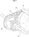
- the external diameter of the stator 3 may be configured by combining different external diameters rather than configuring constant external diameters like a conventional general motor and, thus, a relatively small external diameter may prevent interference with other components such as a driveshaft 27 as described with reference to FIG. 4 , and a relatively large external diameter may sufficiently form a magnetic field of a stator if possible to sufficiently ensure desired output torque by a motor.
- the stator 3 may include a first external diameter portion 5 with a relatively small external diameter, and a second external diameter portion 7 with a larger external diameter than the first external diameter portion 5, and a step difference may be formed between the first external diameter portion 5 and the second external diameter portion 7.
- the stator 3 may include a stator core 9 and a winding 11, the stator core 9 may be configured such that a plurality of first core plates 13 forming the first external diameter portion 5 and a plurality of second core plates 15 forming the second external diameter portion 7 may be formed to overlap with each other, and the winding 11 may be formed within only a range of the first core plates 13, which is for ensuring ease and structural stability of the winding 11.
- the expression of "the winding 11 may be formed within only a range of the first core plates 13" means that the winding 11 may be formed within only a commonly overlapped portion of the first core plates 13 and the second core plates 15.
- the stator 3 may include the first external diameter portion 5 with a relatively small external diameter and the second external diameter portion 7 with a larger external diameter than the first external diameter portion 5, the first external diameter portion 5 having an external diameter gradually increased toward the second external diameter portion 7 to form an oblique cross-section 17.
- the stator 3 may include the stator core 9 and the winding 11, the stator core 9 may be configured such that the plurality of first core plates 13 of which an external diameter is gradually increased to form the oblique cross-section 17 of the first external diameter portion 5 and the plurality of second core plates 15 having a constant external diameter forming the second external diameter portion 7 overlap each other, and the winding 11 may be formed within only a smallest range of the first core plates 13.
- a motor housing 19 that surrounds the stator 3 may be configured outside the stator 3, and a coolant path 21 may be configured in the motor housing 19 to circulate a coolant along a circumference of the stator 3.
- a coolant may forcibly flow through the coolant path 21, effectively cooling heat generated from the motor.
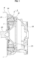
- FIG. 1 illustrates the configuration in which a clutch housing 33 connected to a transmission is coupled to an engine E while surrounding a portion of the motor housing 19.
- internal diameter portions of the stators 3 may be formed with a constant size in a direction of a rotation axis of the rotor 1 to form a section in parallel to the rotation axis of the rotor 1, and a section of the rotor 1 may also be formed in parallel to a rotation axis to correspond the internal diameter and external diameter of the rotor 1 to the internal diameter portion of the stator 3 and, thus, thrust force in an axial direction may not be advantageously generated when rotation force is generated.
- the rotor 1 of the motor may be coupled to a crankshaft 23 of the engine E to be coaxial with the crankshaft 23, as shown in FIG. 1 .
- the rotor 1 may be coupled to the crankshaft 23 through a rotor body 25 which is coupled to the crankshaft 23 through the internal diameter portion of the rotor 1 and, thus, may also provide rotational inertial force to the crankshaft 23 with the rotor body 25 like a flywheel of a conventional engine.
- the stator 3 may be configured such that the first external diameter portion 5 is mounted toward an engine because the first external diameter portion 5 is mounted to face a side in which interference with a driveshaft 27 may occur.
- the driveshaft 27 facing a driving wheel from a trans axle 29 extends along a lower lateral side of an engine block 31
- the driveshaft 27 may interfere with the motor housing 19 and, thus, when a structure of the stator of the motor according to an exemplary embodiment of the present invention is used, the first external diameter portion 5 of the stator 3 may be positioned to surface a side in which the possibility of interference with the driveshaft 27 is high if possible, preventing interference with the driveshaft 27.
- a motor located between an engine and a transmission may be configured to provide sufficient output torque while the whole length of the engine transmission assembly is not increased.
- the present invention may provide a flexible structure for ensuring large output torque of the motor if possible within the present limit.
- a motor mounted between an engine and a transmission may provide sufficient output torque required by the motor while minimizing increase in the whole length of the engine transmission assembly and, thus, vehicle installation of the engine transmission assembly may be enhanced while sufficiently ensuring power performance required by the power train.
Landscapes
- Engineering & Computer Science (AREA)
- Power Engineering (AREA)
- Chemical & Material Sciences (AREA)
- Combustion & Propulsion (AREA)
- Transportation (AREA)
- Mechanical Engineering (AREA)
- Electric Propulsion And Braking For Vehicles (AREA)
- Hybrid Electric Vehicles (AREA)
Abstract
Description
- The present invention relates to a motor for a vehicle, and more particularly, to technology of a motor configuring a hybrid power train with an engine as an internal combustion.
- A hybrid power train of a vehicle enhances fuel efficiency of the vehicle by appropriately combining the characteristics of an engine as an internal combustion and the characteristics of a motor as an electric device.
- A conventional method of additionally disposing a motor in a power train of a vehicle for transferring power of an engine to a driving wheel is broadly classified into a transmission mounted electric device (TMED) method and a flywheel mounted electric device (FMED) method.
- The FMED method is a method of directly coupling a motor as an electric device to a flywheel of an engine and is different from the TMED method of coupling a motor to a transmission side to connect the motor to the engine through an engine clutch.
- In a front engine front drive (FF) vehicle, an assembly configured by coupling an engine and a transmission is mostly mounted in a lateral direction of the vehicle, and in the instant case, the whole length of the engine transmission assembly needs to be accommodated within the width of a vehicular engine compartment in the lateral direction and, thus, one of very important objects in power train design is to reduce the whole length of the engine transmission assembly.
- When a hybrid power train is configured by additionally mounting a motor to the aforementioned engine transmission assembly, the whole length of the engine transmission assembly is increased due to the width of the additionally mounted motor and, thus, a more serious problem arises with vehicle installation.
- A driveshaft extends toward opposite drive wheels from a trans axle which is the transmission included in the engine transmission assembly and, in this regard, presence of the driveshaft that extends toward the engine in the driveshaft is a main design factor for limiting an external diameter of the motor mounted between the trans axle and the engine as described above and, thus, there is a limit in ensuring torque of the motor by enlarging the external diameter.
- The information disclosed in this Background of the Invention section is only for enhancement of understanding of the general background of the invention and may not be taken as an acknowledgement or any form of suggestion that this information forms the prior art already known to a person skilled in the art.
- Various aspects of the present invention are directed to providing a motor configured for a vehicle, which provides sufficient output torque required by the motor while minimizing increase in the whole length of the engine transmission assembly by the motor mounted between an engine and a transmission and, thus, vehicle installation of the engine transmission assembly may be enhanced while sufficiently ensuring power performance required by the power train.
- According to an exemplary embodiment of the present invention, a motor configured for a vehicle may include a rotor, and a stator mounted outside the rotor to form an air gap between the rotor and the stator, wherein the stator may include at least two external diameter portions with different external diameters.
- The stator may include a first external diameter portion, and a second external diameter portion having an external diameter larger than an external diameter of the first external diameter portion, and a step difference is formed between the first external diameter portion and the second external diameter portion.
- The stator may include a stator core and a winding, the stator core may be configured such that a plurality of first core plates forming the first external diameter portion and a plurality of second core plates forming the second external diameter portion are formed to overlap with each other, and the winding may be formed within only a range of the first core plates.
- The motor may further include a motor housing mounted outside the stator to surround the stator, and a coolant path formed in the motor housing to circulate a coolant along a circumference of the stator.
- The stator may include a first external diameter portion with a relatively small external diameter and a second external diameter portion with a larger external diameter than the first external diameter portion, the first external diameter portion having an external diameter gradually increased toward the second external diameter portion to form an oblique cross-section on the first external diameter portion.
- The stator may include a stator core and a winding, the stator core includes a plurality of first core plates of which an external diameter is gradually increased to form the oblique cross-section of the first external diameter portion and a plurality of second core plates having a constant external diameter forming the second external diameter portion overlap each other, and the winding may be formed within only a smallest range of the first core plates.
- According to various exemplary embodiments of the present invention, there is provided a hybrid power train for a vehicle, wherein the rotor of the motor as described above is coupled to a crankshaft of an engine to be coaxial with the crankshaft.
- The stator may be configured such that the first external diameter portion is mounted to surface a side in which interference with a driveshaft may occur.
- The stator may be configured such that the first external diameter portion is mounted toward the engine.
- The methods and apparatuses of the present invention have other features and advantages which will be apparent from or are set forth in more detail in the accompanying drawings, which are incorporated herein, and the following Detailed Description, which together serve to explain certain principles of the present invention.
-
-
FIG. 1 is a cross-sectional view for explanation of a structure of a motor configured for a vehicle according to an exemplary embodiment of the present invention. -
FIG. 2 is a diagram for explanation of a configuration of a stator of the motor ofFIG. 1 . -
FIG. 3 is a diagram for explanation of a configuration of a stator according to various exemplary embodiments of the present invention. -
FIG. 4 is a diagram for explanation of the case in which interference with a driveshaft may occur when an external diameter of a motor is enlarged in a front engine front drive (FF)-type hybrid power train. - It may be understood that the appended drawings are not necessarily to scale, presenting a somewhat simplified representation of various features illustrative of the basic principles of the present invention. The specific design features of the present invention as included herein, including, for example, specific dimensions, orientations, locations, and shapes will be determined in part by the particularly intended application and use environment.
- In the figures, reference numbers refer to the same or equivalent portions of the present invention throughout the several figures of the drawing.
- Reference will now be made in detail to various embodiments of the present invention(s), examples of which are illustrated in the accompanying drawings and described below. While the present invention(s) will be described in conjunction with exemplary embodiments of the present invention, it will be understood that the present description is not intended to limit the present invention(s) to those exemplary embodiments. On the other hand, the present invention(s) is/are intended to cover not only the exemplary embodiments of the present invention, but also various alternatives, modifications, equivalents and other embodiments, which may be included within the spirit and scope of the present invention as defined by the appended claims.
- Referring to
FIG. 1 ,FIG. 2 , andFIG. 3 , all embodiments of the present invention may commonly include arotor 1 and astator 3 which is mounted while forming an air gap outside therotor 1 and, here, thestator 3 may include at least two external diameter portions with different external diameters. - That is, the motor according to an exemplary embodiment of the present invention may be configured by combining portions having different external diameters of the
stator 3, which are not constant. - Accordingly, the external diameter of the
stator 3 may be configured by combining different external diameters rather than configuring constant external diameters like a conventional general motor and, thus, a relatively small external diameter may prevent interference with other components such as adriveshaft 27 as described with reference toFIG. 4 , and a relatively large external diameter may sufficiently form a magnetic field of a stator if possible to sufficiently ensure desired output torque by a motor. - According to an exemplary embodiment of
FIG. 1 andFIG. 2 , thestator 3 may include a firstexternal diameter portion 5 with a relatively small external diameter, and a secondexternal diameter portion 7 with a larger external diameter than the firstexternal diameter portion 5, and a step difference may be formed between the firstexternal diameter portion 5 and the secondexternal diameter portion 7. - In the instant case, the
stator 3 may include astator core 9 and a winding 11, thestator core 9 may be configured such that a plurality offirst core plates 13 forming the firstexternal diameter portion 5 and a plurality ofsecond core plates 15 forming the secondexternal diameter portion 7 may be formed to overlap with each other, and the winding 11 may be formed within only a range of thefirst core plates 13, which is for ensuring ease and structural stability of thewinding 11. - In other words, the expression of "the winding 11 may be formed within only a range of the
first core plates 13" means that the winding 11 may be formed within only a commonly overlapped portion of thefirst core plates 13 and thesecond core plates 15. - According to the exemplary embodiment of
FIG. 3 , thestator 3 may include the firstexternal diameter portion 5 with a relatively small external diameter and the secondexternal diameter portion 7 with a larger external diameter than the firstexternal diameter portion 5, the firstexternal diameter portion 5 having an external diameter gradually increased toward the secondexternal diameter portion 7 to form anoblique cross-section 17. - In the instant case, the
stator 3 may include thestator core 9 and the winding 11, thestator core 9 may be configured such that the plurality offirst core plates 13 of which an external diameter is gradually increased to form theoblique cross-section 17 of the firstexternal diameter portion 5 and the plurality ofsecond core plates 15 having a constant external diameter forming the secondexternal diameter portion 7 overlap each other, and thewinding 11 may be formed within only a smallest range of thefirst core plates 13. - According to both the two embodiments, a
motor housing 19 that surrounds thestator 3 may be configured outside thestator 3, and acoolant path 21 may be configured in themotor housing 19 to circulate a coolant along a circumference of thestator 3. - Accordingly, a coolant may forcibly flow through the
coolant path 21, effectively cooling heat generated from the motor. - For reference,
FIG. 1 illustrates the configuration in which aclutch housing 33 connected to a transmission is coupled to an engine E while surrounding a portion of themotor housing 19. - According to the aforementioned two embodiments, internal diameter portions of the
stators 3 may be formed with a constant size in a direction of a rotation axis of therotor 1 to form a section in parallel to the rotation axis of therotor 1, and a section of therotor 1 may also be formed in parallel to a rotation axis to correspond the internal diameter and external diameter of therotor 1 to the internal diameter portion of thestator 3 and, thus, thrust force in an axial direction may not be advantageously generated when rotation force is generated. - In the above configured vehicle power train using the motor, the
rotor 1 of the motor may be coupled to acrankshaft 23 of the engine E to be coaxial with thecrankshaft 23, as shown inFIG. 1 . - In
FIG. 1 , therotor 1 may be coupled to thecrankshaft 23 through arotor body 25 which is coupled to thecrankshaft 23 through the internal diameter portion of therotor 1 and, thus, may also provide rotational inertial force to thecrankshaft 23 with therotor body 25 like a flywheel of a conventional engine. - According to the exemplary embodiment of the present invention, the
stator 3 may be configured such that the firstexternal diameter portion 5 is mounted toward an engine because the firstexternal diameter portion 5 is mounted to face a side in which interference with adriveshaft 27 may occur. - As described above, as seen from
FIG. 4 , as thedriveshaft 27 facing a driving wheel from atrans axle 29 extends along a lower lateral side of anengine block 31, thedriveshaft 27 may interfere with themotor housing 19 and, thus, when a structure of the stator of the motor according to an exemplary embodiment of the present invention is used, the firstexternal diameter portion 5 of thestator 3 may be positioned to surface a side in which the possibility of interference with thedriveshaft 27 is high if possible, preventing interference with thedriveshaft 27. - As described above, according to an exemplary embodiment of the present invention, a motor located between an engine and a transmission may be configured to provide sufficient output torque while the whole length of the engine transmission assembly is not increased.
- That is, with regard to increase in an external diameter of a motor as a method selected to increase output of the motor in a state in which the whole length of the engine transmission assembly is limited, interference with other components such as a driveshaft limits increase in the external diameter of the motor and, in this regard, the present invention may provide a flexible structure for ensuring large output torque of the motor if possible within the present limit.
- According to an exemplary embodiment of the present invention, a motor mounted between an engine and a transmission may provide sufficient output torque required by the motor while minimizing increase in the whole length of the engine transmission assembly and, thus, vehicle installation of the engine transmission assembly may be enhanced while sufficiently ensuring power performance required by the power train.
- For convenience in explanation and accurate definition in the appended claims, the terms "upper", "lower", "inner", "outer", "up", "down", "upwards", "downwards", "front", "rear", "back", "inside", "outside", "inwardly", "outwardly", "internal", "external", "inner", "outer", "forwards", and "backwards" are used to describe features of the exemplary embodiments with reference to the positions of such features as displayed in the figures. It will be further understood that the term "connect" or its derivatives refer both to direct and indirect connection.
- The foregoing descriptions of specific exemplary embodiments of the present invention have been presented for purposes of illustration and description. They are not intended to be exhaustive or to limit the present invention to the precise forms disclosed, and obviously many modifications and variations are possible in light of the above teachings. The exemplary embodiments were chosen and described to explain certain principles of the present invention and their practical application, to enable others skilled in the art to make and utilize various exemplary embodiments of the present invention, as well as various alternatives and modifications thereof. It is intended that the scope of the present invention be defined by the Claims appended hereto and their equivalents.
Claims (12)
- A motor for a vehicle, the motor comprising:a rotor; anda stator mounted outside the rotor to form an air gap between the rotor and the stator,wherein the stator includes at least two external diameter portions with different external diameters.
- The motor for the vehicle of claim 1,
wherein the at least two external diameter portions of the stator includes a first external diameter portion, and a second external diameter portion having an external diameter larger than an external diameter of the first external diameter portion, and
wherein a step difference is formed between the first external diameter portion and the second external diameter portion. - The motor for the vehicle of claim 1 or 2,
wherein the stator includes a stator core and a winding;
wherein the stator core includes a plurality of first core plates forming the first external diameter portion and a plurality of second core plates forming the second external diameter portion, the plurality of first core plates formed to overlap with the plurality of second core plates; and
wherein the winding is formed at a portion commonly overlapped with the plurality of first core plates and the plurality of second core plates. - The motor for the vehicle of one of claims 1-3, further including:a motor housing mounted outside the stator to surround the stator; anda coolant path formed in the motor housing to circulate a coolant along a circumference of the stator.
- The motor for the vehicle of one of claims 1-4,
wherein the at least two external diameter portions of the stator includes a first external diameter portion, and a second external diameter portion having an external diameter larger than an external diameter of the first external diameter portion, and
wherein the first external diameter portion has an external diameter formed to be increased toward the second external diameter portion to form an oblique cross-section on the first external diameter portion. - The motor for the vehicle of claim 5,
wherein the stator includes a stator core and a winding;
wherein the stator core includes a plurality of first core plates of which an external diameter is increased to form the oblique cross-section of the first external diameter portion and a plurality of second core plates having a constant external diameter forming the second external diameter portion, the plurality of first core plates formed to overlap with the plurality of second core plates; and
wherein the winding is formed within a smallest range of the first core plates. - A hybrid power train for the vehicle of claim 2 or of one of claims 1, 3-6 in combination with claim 2,
wherein the rotor of the motor is coupled to a crankshaft of an engine to be coaxial with the crankshaft. - The hybrid power train for the vehicle of claim 7,
wherein the first external diameter portion of the stator is mounted to face a side in which interference with a driveshaft occurs. - The hybrid power train for the vehicle of claim 7 or 8,
wherein the first external diameter portion of the stator is mounted toward the engine. - A hybrid power train for the vehicle of one of claims 1-9,
wherein the rotor of the motor is coupled to a crankshaft of an engine to be coaxial with the crankshaft. - The hybrid power train for the vehicle of claim 10,
wherein the first external diameter portion of the stator is mounted to face a side in which interference with a driveshaft occurs. - The hybrid power train for the vehicle of claim 10 or 11,
wherein the first external diameter portion of the stator is mounted to face the engine.
Applications Claiming Priority (1)
| Application Number | Priority Date | Filing Date | Title |
|---|---|---|---|
| KR1020190030775A KR20200111328A (en) | 2019-03-18 | 2019-03-18 | Motor for vehicle |
Publications (1)
| Publication Number | Publication Date |
|---|---|
| EP3713054A1 true EP3713054A1 (en) | 2020-09-23 |
Family
ID=67551073
Family Applications (1)
| Application Number | Title | Priority Date | Filing Date |
|---|---|---|---|
| EP19190065.3A Withdrawn EP3713054A1 (en) | 2019-03-18 | 2019-08-05 | Motor for vehicle |
Country Status (3)
| Country | Link |
|---|---|
| US (1) | US20200303972A1 (en) |
| EP (1) | EP3713054A1 (en) |
| KR (1) | KR20200111328A (en) |
Citations (4)
| Publication number | Priority date | Publication date | Assignee | Title |
|---|---|---|---|---|
| US5482512A (en) * | 1994-04-12 | 1996-01-09 | General Motors Corporation | Electro-mechanical hybrid powertrain with self-engaging brakes for starting the engine |
| US20070175726A1 (en) * | 2004-06-03 | 2007-08-02 | Peugeot Citroen Automobiles Sa | Hydraulic clutch transmission element for a hybrid traction chain of a motor vechicle, and motor vehicle comprising one such element |
| US7737599B2 (en) * | 2006-02-23 | 2010-06-15 | Toyota Jidosha Kabushiki Kaisha | Securing structure for stator and electric vehicle |
| DE102009030135A1 (en) * | 2009-06-24 | 2010-12-30 | Dr. Ing. H.C. F. Porsche Aktiengesellschaft | Hybrid powertrain |
Family Cites Families (1)
| Publication number | Priority date | Publication date | Assignee | Title |
|---|---|---|---|---|
| CN105335065A (en) | 2015-10-10 | 2016-02-17 | 腾讯科技(深圳)有限公司 | Information processing method and terminal, and computer storage medium |
-
2019
- 2019-03-18 KR KR1020190030775A patent/KR20200111328A/en not_active Ceased
- 2019-08-05 EP EP19190065.3A patent/EP3713054A1/en not_active Withdrawn
- 2019-08-05 US US16/531,389 patent/US20200303972A1/en not_active Abandoned
Patent Citations (4)
| Publication number | Priority date | Publication date | Assignee | Title |
|---|---|---|---|---|
| US5482512A (en) * | 1994-04-12 | 1996-01-09 | General Motors Corporation | Electro-mechanical hybrid powertrain with self-engaging brakes for starting the engine |
| US20070175726A1 (en) * | 2004-06-03 | 2007-08-02 | Peugeot Citroen Automobiles Sa | Hydraulic clutch transmission element for a hybrid traction chain of a motor vechicle, and motor vehicle comprising one such element |
| US7737599B2 (en) * | 2006-02-23 | 2010-06-15 | Toyota Jidosha Kabushiki Kaisha | Securing structure for stator and electric vehicle |
| DE102009030135A1 (en) * | 2009-06-24 | 2010-12-30 | Dr. Ing. H.C. F. Porsche Aktiengesellschaft | Hybrid powertrain |
Also Published As
| Publication number | Publication date |
|---|---|
| KR20200111328A (en) | 2020-09-29 |
| US20200303972A1 (en) | 2020-09-24 |
Similar Documents
| Publication | Publication Date | Title |
|---|---|---|
| US7975571B2 (en) | Hybrid drive device | |
| EP3778280B1 (en) | Engine and electric motor assembly, and vehicle driving device | |
| EP3461669B1 (en) | Hybrid vehicle | |
| US11781635B2 (en) | Motor unit | |
| EP1093958A2 (en) | Vehicle drive unit | |
| CN101176249A (en) | Engine-mounted generator/motor | |
| EP3795820B1 (en) | Engine-and-electric-machine assembly | |
| EP3796524B1 (en) | Engine-and-electric-machine assembly | |
| JP4747880B2 (en) | Stator fixing structure and electric vehicle | |
| US20190376589A1 (en) | Parallel Strong Hybrid Electric Vehicle (Hev) Powertrain Assembly With Torque Converter | |
| CN112714994A (en) | Rotating electrical machine | |
| KR20230081804A (en) | In-Wheel Motor Assembly Having Rotor Bracket Having Cooling Aid Protrusion | |
| US20200303972A1 (en) | Motor for vehicle | |
| CN211063482U (en) | An engine and motor assembly | |
| CN107972470B (en) | drive train device | |
| CN107975422B (en) | Drive train | |
| US20200158205A1 (en) | Damper for engine mounted with motor | |
| US20120049675A1 (en) | Electric power generating differential | |
| CN221113494U (en) | Power assembly and electric vehicle | |
| CN221328698U (en) | Electric drive system | |
| US20240380272A1 (en) | Electric machine | |
| JP2010064610A (en) | Power output device, hybrid vehicle and drive unit | |
| KR102696383B1 (en) | Gear assembly | |
| US10259306B1 (en) | Oblique motor |
Legal Events
| Date | Code | Title | Description |
|---|---|---|---|
| PUAI | Public reference made under article 153(3) epc to a published international application that has entered the european phase |
Free format text: ORIGINAL CODE: 0009012 |
|
| STAA | Information on the status of an ep patent application or granted ep patent |
Free format text: STATUS: THE APPLICATION HAS BEEN PUBLISHED |
|
| AK | Designated contracting states |
Kind code of ref document: A1 Designated state(s): AL AT BE BG CH CY CZ DE DK EE ES FI FR GB GR HR HU IE IS IT LI LT LU LV MC MK MT NL NO PL PT RO RS SE SI SK SM TR |
|
| AX | Request for extension of the european patent |
Extension state: BA ME |
|
| STAA | Information on the status of an ep patent application or granted ep patent |
Free format text: STATUS: REQUEST FOR EXAMINATION WAS MADE |
|
| 17P | Request for examination filed |
Effective date: 20210126 |
|
| RBV | Designated contracting states (corrected) |
Designated state(s): AL AT BE BG CH CY CZ DE DK EE ES FI FR GB GR HR HU IE IS IT LI LT LU LV MC MK MT NL NO PL PT RO RS SE SI SK SM TR |
|
| RAP3 | Party data changed (applicant data changed or rights of an application transferred) |
Owner name: HYUNDAI MOTOR COMPANY Owner name: KIA CORPORATION |
|
| STAA | Information on the status of an ep patent application or granted ep patent |
Free format text: STATUS: EXAMINATION IS IN PROGRESS |
|
| 17Q | First examination report despatched |
Effective date: 20211206 |
|
| P01 | Opt-out of the competence of the unified patent court (upc) registered |
Effective date: 20230505 |
|
| REG | Reference to a national code |
Ref country code: DE Ref legal event code: R079 Free format text: PREVIOUS MAIN CLASS: H02K0005200000 Ipc: H02K0007000000 |
|
| GRAP | Despatch of communication of intention to grant a patent |
Free format text: ORIGINAL CODE: EPIDOSNIGR1 |
|
| STAA | Information on the status of an ep patent application or granted ep patent |
Free format text: STATUS: GRANT OF PATENT IS INTENDED |
|
| RIC1 | Information provided on ipc code assigned before grant |
Ipc: H02K 5/20 20060101ALI20231111BHEP Ipc: B60K 6/485 20071001ALI20231111BHEP Ipc: B60K 6/26 20071001ALI20231111BHEP Ipc: H02K 7/00 20060101AFI20231111BHEP |
|
| INTG | Intention to grant announced |
Effective date: 20231212 |
|
| STAA | Information on the status of an ep patent application or granted ep patent |
Free format text: STATUS: THE APPLICATION IS DEEMED TO BE WITHDRAWN |
|
| 18D | Application deemed to be withdrawn |
Effective date: 20240413 |