EP3713038B1 - Charging station and charging system, method and apparatus - Google Patents
Charging station and charging system, method and apparatus Download PDFInfo
- Publication number
- EP3713038B1 EP3713038B1 EP18880023.9A EP18880023A EP3713038B1 EP 3713038 B1 EP3713038 B1 EP 3713038B1 EP 18880023 A EP18880023 A EP 18880023A EP 3713038 B1 EP3713038 B1 EP 3713038B1
- Authority
- EP
- European Patent Office
- Prior art keywords
- switch
- power supply
- charging
- access switch
- battery
- Prior art date
- Legal status (The legal status is an assumption and is not a legal conclusion. Google has not performed a legal analysis and makes no representation as to the accuracy of the status listed.)
- Active
Links
Images


Classifications
-
- B—PERFORMING OPERATIONS; TRANSPORTING
- B60—VEHICLES IN GENERAL
- B60L—PROPULSION OF ELECTRICALLY-PROPELLED VEHICLES; SUPPLYING ELECTRIC POWER FOR AUXILIARY EQUIPMENT OF ELECTRICALLY-PROPELLED VEHICLES; ELECTRODYNAMIC BRAKE SYSTEMS FOR VEHICLES IN GENERAL; MAGNETIC SUSPENSION OR LEVITATION FOR VEHICLES; MONITORING OPERATING VARIABLES OF ELECTRICALLY-PROPELLED VEHICLES; ELECTRIC SAFETY DEVICES FOR ELECTRICALLY-PROPELLED VEHICLES
- B60L53/00—Methods of charging batteries, specially adapted for electric vehicles; Charging stations or on-board charging equipment therefor; Exchange of energy storage elements in electric vehicles
- B60L53/30—Constructional details of charging stations
-
- B—PERFORMING OPERATIONS; TRANSPORTING
- B60—VEHICLES IN GENERAL
- B60L—PROPULSION OF ELECTRICALLY-PROPELLED VEHICLES; SUPPLYING ELECTRIC POWER FOR AUXILIARY EQUIPMENT OF ELECTRICALLY-PROPELLED VEHICLES; ELECTRODYNAMIC BRAKE SYSTEMS FOR VEHICLES IN GENERAL; MAGNETIC SUSPENSION OR LEVITATION FOR VEHICLES; MONITORING OPERATING VARIABLES OF ELECTRICALLY-PROPELLED VEHICLES; ELECTRIC SAFETY DEVICES FOR ELECTRICALLY-PROPELLED VEHICLES
- B60L3/00—Electric devices on electrically-propelled vehicles for safety purposes; Monitoring operating variables, e.g. speed, deceleration or energy consumption
- B60L3/0023—Detecting, eliminating, remedying or compensating for drive train abnormalities, e.g. failures within the drive train
- B60L3/0069—Detecting, eliminating, remedying or compensating for drive train abnormalities, e.g. failures within the drive train relating to the isolation, e.g. ground fault or leak current
-
- H—ELECTRICITY
- H02—GENERATION; CONVERSION OR DISTRIBUTION OF ELECTRIC POWER
- H02J—ELECTRIC POWER NETWORKS; CIRCUIT ARRANGEMENTS OR SYSTEMS FOR SUPPLYING OR DISTRIBUTING ELECTRIC POWER; SYSTEMS FOR STORING ELECTRIC ENERGY
- H02J7/00—Circuit arrangements for charging or discharging batteries or for supplying loads from batteries
- H02J7/50—Circuit arrangements for charging or discharging batteries or for supplying loads from batteries acting upon multiple batteries simultaneously or sequentially
-
- H—ELECTRICITY
- H02—GENERATION; CONVERSION OR DISTRIBUTION OF ELECTRIC POWER
- H02J—ELECTRIC POWER NETWORKS; CIRCUIT ARRANGEMENTS OR SYSTEMS FOR SUPPLYING OR DISTRIBUTING ELECTRIC POWER; SYSTEMS FOR STORING ELECTRIC ENERGY
- H02J2105/00—Networks for supplying or distributing electric power characterised by their spatial reach or by the load
- H02J2105/30—Networks for supplying or distributing electric power characterised by their spatial reach or by the load the load networks being external to vehicles, i.e. exchanging power with vehicles
- H02J2105/33—Networks for supplying or distributing electric power characterised by their spatial reach or by the load the load networks being external to vehicles, i.e. exchanging power with vehicles exchanging power with road vehicles
- H02J2105/37—Networks for supplying or distributing electric power characterised by their spatial reach or by the load the load networks being external to vehicles, i.e. exchanging power with vehicles exchanging power with road vehicles exchanging power with electric vehicles [EV] or with hybrid electric vehicles [HEV]
-
- H—ELECTRICITY
- H02—GENERATION; CONVERSION OR DISTRIBUTION OF ELECTRIC POWER
- H02J—ELECTRIC POWER NETWORKS; CIRCUIT ARRANGEMENTS OR SYSTEMS FOR SUPPLYING OR DISTRIBUTING ELECTRIC POWER; SYSTEMS FOR STORING ELECTRIC ENERGY
- H02J7/00—Circuit arrangements for charging or discharging batteries or for supplying loads from batteries
- H02J7/80—Circuit arrangements for charging or discharging batteries or for supplying loads from batteries including monitoring or indicating arrangements
-
- Y—GENERAL TAGGING OF NEW TECHNOLOGICAL DEVELOPMENTS; GENERAL TAGGING OF CROSS-SECTIONAL TECHNOLOGIES SPANNING OVER SEVERAL SECTIONS OF THE IPC; TECHNICAL SUBJECTS COVERED BY FORMER USPC CROSS-REFERENCE ART COLLECTIONS [XRACs] AND DIGESTS
- Y02—TECHNOLOGIES OR APPLICATIONS FOR MITIGATION OR ADAPTATION AGAINST CLIMATE CHANGE
- Y02T—CLIMATE CHANGE MITIGATION TECHNOLOGIES RELATED TO TRANSPORTATION
- Y02T10/00—Road transport of goods or passengers
- Y02T10/60—Other road transportation technologies with climate change mitigation effect
- Y02T10/70—Energy storage systems for electromobility, e.g. batteries
-
- Y—GENERAL TAGGING OF NEW TECHNOLOGICAL DEVELOPMENTS; GENERAL TAGGING OF CROSS-SECTIONAL TECHNOLOGIES SPANNING OVER SEVERAL SECTIONS OF THE IPC; TECHNICAL SUBJECTS COVERED BY FORMER USPC CROSS-REFERENCE ART COLLECTIONS [XRACs] AND DIGESTS
- Y02—TECHNOLOGIES OR APPLICATIONS FOR MITIGATION OR ADAPTATION AGAINST CLIMATE CHANGE
- Y02T—CLIMATE CHANGE MITIGATION TECHNOLOGIES RELATED TO TRANSPORTATION
- Y02T10/00—Road transport of goods or passengers
- Y02T10/60—Other road transportation technologies with climate change mitigation effect
- Y02T10/7072—Electromobility specific charging systems or methods for batteries, ultracapacitors, supercapacitors or double-layer capacitors
-
- Y—GENERAL TAGGING OF NEW TECHNOLOGICAL DEVELOPMENTS; GENERAL TAGGING OF CROSS-SECTIONAL TECHNOLOGIES SPANNING OVER SEVERAL SECTIONS OF THE IPC; TECHNICAL SUBJECTS COVERED BY FORMER USPC CROSS-REFERENCE ART COLLECTIONS [XRACs] AND DIGESTS
- Y02—TECHNOLOGIES OR APPLICATIONS FOR MITIGATION OR ADAPTATION AGAINST CLIMATE CHANGE
- Y02T—CLIMATE CHANGE MITIGATION TECHNOLOGIES RELATED TO TRANSPORTATION
- Y02T90/00—Enabling technologies or technologies with a potential or indirect contribution to GHG emissions mitigation
- Y02T90/10—Technologies relating to charging of electric vehicles
- Y02T90/12—Electric charging stations
Definitions
- the invention relates to the technical field of battery charging and swapping for electric vehicles, and in particular to a charging station, a charging system and method, and apparatuses.
- a high-voltage relay in the traction battery is controlled to be closed to form a power supply circuit. Based on the method described above, it can be ensured that the traction battery has been connected to the load when supplying power to the outside, so that when an electric vehicle is shut down or stopped, the traction battery is disconnected from an electric device in the electric vehicle.
- the standby loss of the traction battery can be reduced.
- bypass resistor When a traction battery is charged based on the power supply method described above, it is often necessary to connect a bypass resistor in parallel across the traction battery, so that the battery management system controls, when a bypass current is detected, a high-voltage relay to be closed, so as to form a charging circuit.
- the bypass resistor being connected in parallel across the traction battery can not only increase power losses and manufacturing costs, but also cause certain safety concerns when the bypass resistor breaks down.
- JP 2003 169401 A relates to a power supply device having a leakage detection circuit for accurately detecting a leakage.
- CN 104 600 815 A relates to an electric vehicle charging system and a charging control method.
- CN 101 073 990 A relates to an electric vehicle power supply system with a high-voltage safety protection device, and a control method for safety protection of an electric vehicle power supply system.
- the invention provides a charging station, a charging system and method, and an apparatus.
- a first aspect of the invention is directed to a charging system, whose scope is defined by claim 1.
- said charging system comprises a power interface, a battery interface, power supply access switches, battery access switches, a pre-charging switch, an insulation monitoring module, and a controller,
- the power supply access switches are separately connected to positive and negative electrodes of the power interface
- the battery access switches are separately connected to positive and negative electrodes of the battery interface
- the pre-charging switch is connected in parallel with one of the battery access switches
- the insulation monitoring module is provided on a direct current bus bar between the power interface and a power supply access switch
- the controller is configured to control, when starting charging, the insulation monitoring module, power supply access switches, the pre-charging switch, a battery, and one of the battery access switches to form a current path, so as to close the other of the battery access switches after current is detected in the current path; and the controller is further configured to control, during a charging process, the insulation monitoring module to monitor an insulation resistance to ground of the direct current bus
- the insulation monitoring module comprises a positive switch, a negative switch, a positive resistor, and a negative resistor; one end of the positive switch is grounded, and the other end thereof is connected to the positive direct current bus bar in the direct current bus bar through the positive resistor; and one end of the negative switch is grounded, and the other end thereof is connected to the negative direct current bus bar in the direct current bus bar through the negative resistor.
- the power supply conversion module is an AC/DC module or a DC/DC module.
- a second aspect of the invention is directed to a charging station, whose scope is defined by claim 9.
- Said charging station comprises a traction battery charging position and a charging system being an embodiment of the first aspect;
- a third aspect of the invention is directed to a charging method, whose scope is defined by claim 10. Said charging is used in a charging system, the charging system being an embodiment of the first aspect, wherein the method is used to control the charging system to charge a battery, which is specifically as follows:
- a fourth aspect of the invention is directed to a storage apparatus, whose scope is defined by claim 12.
- Said storage apparatus has a plurality of programs stored therein, wherein the programs are adapted to be loaded and executed by a processor to implement a charging method as described in the third aspect above.
- a fifth aspect of the invention is directed to a processing apparatus, whose scope is defined by claim 13.
- Said processing apparatus comprises comprises a processor and a storage device.
- the processor is adapted to execute various programs; and the storage device is adapted to store a plurality of programs.
- the programs are adapted to be loaded and executed by the processor to implement a charging method as described in the third aspect above.
- the charging system in the invention may control, by means of a controller when starting charging, an insulation monitoring module, power supply access switches, a pre-charging switch, a battery, and a battery access switch to form a current path, so as to close the other battery access switch after current is detected in the current path, i.e., controlling conventional devices in the charging circuit to form a current path without the need to provide a bypass resistor, so that not only manufacturing costs of the charging system are reduced, but also safety concerns and power losses that are caused by the bypass resistor are avoided, and the electrical safety of the charging system is improved.
- a signal relay can be added to disconnect, after a battery relay is closed, the traction battery from the bypass resistor by opening the signal relay.
- a charging system which can control, in a safe and reliable manner, a battery relay to be closed without adding any components.
- FIG. 1 exemplarily shows the structure of a charging system in this embodiment.
- the charging system in this embodiment may comprise a power interface 11, a battery interface 12, two power supply access switches 13, two battery access switches 14, a pre-charging switch 15, an insulation monitoring module 16, and a controller 17.
- the two power supply access switches 14 are separately connected to positive and negative electrodes of the power interface 11
- the two battery access switches 14 are separately connected to positive and negative electrodes of the battery interface 12
- the pre-charging switch 15 is connected in parallel with one battery access switch 14 (as shown in FIG. 1 , the pre-charging switch 15 is connected in parallel with the battery access switch 14 provided on a positive direct current bus bar 18)
- the insulation monitoring module 16 is provided on a direct current bus bar between the power interface 11 and a power supply access switch 13 (as shown in FIG. 1 , two ends of the insulation monitoring module 16 are separately connected to the positive direct current bus bar 18 and a negative direct current bus bar 19).
- the power supply access switch 13 may be a relay or a controllable semiconductor switch
- the battery access switch 14 may also be a relay or a controllable semiconductor switch
- the pre-charging switch 15 may also be a relay or a controllable semiconductor switch.
- the controller 17 may be configured to control, when starting charging, the insulation monitoring module 16, the power supply access switch 13, the pre-charging switch 15, the battery, and one of the battery access switches 14 (as shown in FIG. 1 , the battery access switch is a battery access switch provided on the negative direct current bus bar 19) to form a current path, so as to close the other of the battery access switches 14 (as shown in FIG. 1 , the battery access switch is a battery access switch provided on the positive direct current bus bar 18) after current is detected in the current path.
- there is no need to provide a bypass resistor across the battery By controlling the insulation monitoring module 16 and the battery to form a current path, both the battery access switches can be automatically controlled to be closed after current is detected in the current path, so as to complete a starting process of battery charging.
- the controller 17 may be further configured to control, when entering a charging process after the starting of charging is completed, the insulation monitoring module 16 to monitor an insulation resistance to ground of the direct current bus bar.
- the insulation monitoring module 16 may be a conventional direct current insulation monitoring module.
- FIG. 3 shows the structure of an insulation monitoring module in this embodiment.
- the insulation monitoring module of the invention must comprise a positive switch Relayl and a negative switch Relay2, at least a positive resistor (e.g. R 1 and R 2 ), and at least a negative resistor (R 3 and R 4 ).
- One end of the positive switch Relayl is grounded, and the other end thereof is connected to a positive electrode of a direct current power supply V pv through the at least one positive resistor R 2 and R 1 in sequence.
- One end of the negative switch Relay2 is grounded, and the other end thereof is connected to a negative electrode of the direct current power supply V pv through the at least one negative resistor R 4 and R 3 in sequence.
- the positive switch Relay1 when the insulation monitoring module shown in FIG. 3 is provided on the direct current bus bar between the power interface 11 and the power supply access switch 13 shown in FIG. 1 , one end of the positive switch Relay1 is grounded, and the other end thereof is connected to the positive direct current bus bar 18 through the positive resistors R 2 and R 1 in sequence.
- One end of the negative switch Relay2 is grounded, and the other end thereof is connected to the negative direct current bus bar 19 through the negative resistors R 4 and R 3 in sequence.
- the positive switch Relay1 may be a relay or a controllable semiconductor switch
- the negative switch Relay2 may also be a relay or a controllable semiconductor switch.
- the insulation monitoring module can monitor insulation resistances R x and R y to ground of positive and negative electrodes in the direct current power supply V pv according to steps which are specifically as follows:
- controller 17 in the charging system shown in FIG. 1 in this embodiment may comprise a first control module and a second control module.
- the first control module in this embodiment may be configured to perform the following operations:
- the insulation monitoring module 16 may be the insulation monitoring module shown in FIG. 3 .
- the preset first control instruction in this embodiment may be an instruction for controlling the positive switch Relayl and the negative switch Relay2 to be closed at the same time.
- the preset second control instruction is an instruction for controlling the positive switch Relayl and the negative switch Relay2 to be opened at the same time.
- the second control module in this embodiment may be configured to perform the following operations:
- the insulation resistances to ground of the positive and negative direct current bus bars can be calculated by means of the method shown in formula (1).
- the charging system shown in FIG. 1 in this embodiment may further comprise a power supply conversion module, wherein an input side of the power supply conversion module is connected to the power interface 11, and an output side thereof is connected to the power supply access switch 13.
- a power supply conversion module may be configured to convert an alternating/direct current charging power supply connected to the power interface 11 into a direct current charging power supply available for a battery.
- the power supply conversion module may be an AC/DC module or a DC/DC module.
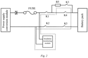
- FIG. 2 exemplarily shows the structure of another charging system in this embodiment.
- the charging system in this embodiment may comprise a power supply conversion module, a power supply access switch K1, a power supply access switch K2, a pre-charging switch K3, a pre-charging resistor R5, a battery access switch K4, a battery access switch K5, and an insulation monitoring module.
- an input side of the power supply conversion module is connected to a power interface (as shown in FIG. 1 ), and positive and negative electrodes at an output side of the power supply conversion module are separately connected to the power supply access switch K1 and the power supply access switch K2.
- One end of the battery access switch K4 is connected to the power supply access switch K1, and the other end thereof is connected to a positive electrode of a battery interface (as shown in FIG. 1 ).
- One end of the battery access switch K5 is connected to the battery access switch K2, and the other end thereof is connected to a negative electrode of the battery interface (as shown in FIG. 1 ), wherein the battery interface is connected to a battery pack.
- the pre-charging switch K3 and the pre-charging resistor R5 are connected in parallel across the battery access switch K4.
- FIG. 4 exemplarily shows the structure of a charging system using the insulation monitoring module shown in FIG. 3 in this embodiment.
- a positive resistor R 1 of the insulation monitoring module is connected to a positive direct current bus bar
- a negative resistor R 3 thereof is connected to a negative direct current bus bar.
- the charging system further comprises a controller, which has the same function as the controller 17 (as shown in FIG. 1 ) in the above-mentioned embodiment of the charging system.
- a first control module in the controller may be configured to perform the following operations:
- the insulation resistances to ground of the positive and negative direct current bus bars can be calculated by means of the method shown in formula (1).
- the charging system further comprises some other well-known structures, such as a processor, a memory, etc.
- the memory includes, but is not limited to, a random access memory, a flash memory, a read-only memory, a programmable read-only memory, and a volatile memory, a non-volatile memory, a serial memory, a parallel memory or a register, etc.
- the processor includes, but is not limited to, a CPLD/FPGA, a DSP, an ARM processor, an MIPS processor, etc. In order to not unnecessarily obscure embodiments of the disclosure, these well-known structures are not shown in FIGs. 1 , 2 , and 4 .
- FIGs. 1 , 2 and 4 are only schematic. According to actual needs, there may be any number of each type of devices.
- the invention further provides a charging station, which may comprise a traction battery charging position, and a charging system as described in the system embodiment above.
- the traction battery charging position is provided with a power supply interface, and a power interface in the charging system (as shown in FIG. 1 ) may be connected to the power supply interface.
- the charging station in this embodiment refers to a charging station, a battery swap station, a battery charging and swap station, or an energy storage power station that comprises the traction battery charging position, i.e., the technical solutions in which the charging system is provided in the charging station, the battery swap station, the battery charging and swap station, and the energy storage power station to charge a traction battery in a safe and reliable manner will all fall within the scope of protection of the invention if they comprise all features of the charging system defined by claim 1.
- the invention further provides a charging method, which can be used to control a charging system as described in the system embodiment above to charge a battery.
- the charging method in this embodiment may be used to control a charging system to charge a battery according to steps which are specifically as follows:
- the method in this embodiment may be further used to control, during a charging process, the insulation monitoring module (as shown in FIG. 4 ) to monitor an insulation resistance to ground of the direct current bus bar, which is specifically as follows:
- the invention further provides a storage apparatus which can store a plurality of programs, wherein these programs may be loaded and executed by a processor to implement a charging method described in the method embodiment above.
- the invention further provides a processing apparatus, which comprises a processor and a storage device.
- the processor may be adapted to execute various programs
- the storage device may be adapted to store a plurality of programs. These programs may be loaded and executed by the processor to implement a charging method as described in the method embodiment above.
Landscapes
- Engineering & Computer Science (AREA)
- Power Engineering (AREA)
- Transportation (AREA)
- Mechanical Engineering (AREA)
- Life Sciences & Earth Sciences (AREA)
- Sustainable Development (AREA)
- Sustainable Energy (AREA)
- Charge And Discharge Circuits For Batteries Or The Like (AREA)
- Secondary Cells (AREA)
Description
- The invention relates to the technical field of battery charging and swapping for electric vehicles, and in particular to a charging station, a charging system and method, and apparatuses.
- Currently, when controlling a traction battery to supply power to a load, it is first necessary to determine, by means of a battery management system, whether the load is connected. After it is determined that the load is connected, a high-voltage relay in the traction battery is controlled to be closed to form a power supply circuit. Based on the method described above, it can be ensured that the traction battery has been connected to the load when supplying power to the outside, so that when an electric vehicle is shut down or stopped, the traction battery is disconnected from an electric device in the electric vehicle. In addition, when a power supply system to which the traction battery belongs is in a standby state, the standby loss of the traction battery can be reduced.
- When a traction battery is charged based on the power supply method described above, it is often necessary to connect a bypass resistor in parallel across the traction battery, so that the battery management system controls, when a bypass current is detected, a high-voltage relay to be closed, so as to form a charging circuit. However, the bypass resistor being connected in parallel across the traction battery can not only increase power losses and manufacturing costs, but also cause certain safety concerns when the bypass resistor breaks down.
-
JP 2003 169401 A CN 104 600 815 A relates to an electric vehicle charging system and a charging control method.CN 101 073 990 A relates to an electric vehicle power supply system with a high-voltage safety protection device, and a control method for safety protection of an electric vehicle power supply system. - The invention is defined by the independent claims. Further embodiments of the invention are defined by the dependent claims.
- In order to solve the above-mentioned problems in the prior art, i.e., solving the technical problem of how to control a high-voltage relay in a traction battery to be closed so as to form a charging circuit, without adding a bypass resistor, the invention provides a charging station, a charging system and method, and an apparatus.
- A first aspect of the invention is directed to a charging system, whose scope is defined by claim 1. In a non-limiting manner, said charging system comprises a power interface, a battery interface, power supply access switches, battery access switches, a pre-charging switch, an insulation monitoring module, and a controller,
- wherein the power supply access switches are separately connected to positive and negative electrodes of the power interface, the battery access switches are separately connected to positive and negative electrodes of the battery interface, the pre-charging switch is connected in parallel with one of the battery access switches, and the insulation monitoring module is provided on a direct current bus bar between the power interface and a power supply access switch;
- the controller is configured to control, when starting charging, the insulation monitoring module, power supply access switches, the pre-charging switch, a battery, and one of the battery access switches to form a current path, so as to close the other of the battery access switches after current is detected in the current path; and the controller is further configured to control, during a charging process, the insulation monitoring module to monitor an insulation resistance to ground of the direct current bus
- The insulation monitoring module comprises a positive switch, a negative switch, a positive resistor, and a negative resistor; one end of the positive switch is grounded, and the other end thereof is connected to the positive direct current bus bar in the direct current bus bar through the positive resistor; and one end of the negative switch is grounded, and the other end thereof is connected to the negative direct current bus bar in the direct current bus bar through the negative resistor.
- Further, one preferred technical solution provided in the invention is as follows:
- the controller comprises a first control module; and the first control module is configured to perform the following operations:
- controlling, when starting charging, the power supply access switch, the pre-charging switch and one of the battery access switches to be closed;
- sending a preset first control instruction to the insulation monitoring module to form the current path when the power supply access switch is closed, wherein the preset first control instruction is an instruction capable of conducting positive and negative direct current bus bars in the direct current bus bar; and
- controlling the other of the battery access switches to be closed, and sending a preset second control instruction to the insulation monitoring module to cut off the current path, wherein the preset second control instruction is an instruction capable of disconnecting the conducted positive and negative direct current bus bars.
- Further, one preferred technical solution provided in the invention is as follows:
- the controller further comprises a second control module; and the second control module is configured to perform the following operations:
- controlling the positive switch to be closed and the negative switch to be opened, so as to detect an insulation resistance to ground of the positive direct current bus bar in the direct current bus bar; and
- controlling the negative switch to be closed and the positive switch to be opened, so as to detect an insulation resistance to ground of the negative direct current bus bar in the direct current bus bar.
- Further, one preferred technical solution provided in the invention is as follows:
- the preset first control instruction is to control the positive switch and the negative switch to be closed at the same time; and
- the preset second control instruction is to control the positive switch and the negative switch to be opened at the same time.
- Further, one preferred technical solution provided in the invention is as follows:
- the power supply access switch is a relay or a controllable semiconductor switch;
- the battery access switch is a relay or a controllable semiconductor switch; and
- the pre-charging switch is a relay or a controllable semiconductor switch.
- Further, one preferred technical solution provided in the invention is as follows:
- the positive switch is a relay or a controllable semiconductor switch; and
- the negative switch is a relay or a controllable semiconductor switch.
- Further, one preferred technical solution provided in the invention is as follows:
- the system further comprises a power supply conversion module, wherein an input side of the power supply conversion module is connected to the power interface, and an output side thereof is connected to the power supply access switch; and
- the power supply conversion module is configured to convert an alternating/direct current charging power supply connected to the power interface into a direct current charging power supply available for a battery.
- Further, one preferred technical solution provided in the invention is as follows:
the power supply conversion module is an AC/DC module or a DC/DC module. - A second aspect of the invention is directed to a charging station, whose scope is defined by claim 9. Said charging station comprises a traction battery charging position and a charging system being an embodiment of the first aspect;
- the traction battery charging position is provided with a power supply interface; and
- a power interface in the charging system is connected to the power supply interface.
- A third aspect of the invention is directed to a charging method, whose scope is defined by claim 10. Said charging is used in a charging system, the charging system being an embodiment of the first aspect, wherein the method is used to control the charging system to charge a battery, which is specifically as follows:
- controlling the power supply access switches, the pre-charging switch and one of the battery access switches in the charging system to be closed;
- detecting whether the power supply access switch is closed, and if yes, sending a preset first control instruction to an insulation monitoring module in the charging system to form the current path, wherein the preset first control instruction is an instruction capable of conducting positive and negative direct current bus bars in the direct current bus bar; and
- controlling the other of the battery access switches in the charging system to be closed, and sending a preset second control instruction to the insulation monitoring module to cut off the current path, wherein the preset second control instruction is an instruction capable of disconnecting the conducted positive and negative direct current bus bars.
- Further, one preferred technical solution provided in the invention is as follows:
- the method is further used to control, during a charging process, the insulation monitoring module to monitor an insulation resistance to ground of the direct current bus bar, which is specifically as follows:
- controlling a positive switch in the insulation monitoring module to be closed and a negative switch to be opened, so as to detect an insulation resistance to ground of the positive direct current bus bar in the direct current bus bar; and
- controlling the negative switch in the insulation monitoring module to be closed and the positive switch to be opened, so as to detect an insulation resistance to ground of the negative direct current bus bar in the direct current bus bar.
- A fourth aspect of the invention is directed to a storage apparatus, whose scope is defined by claim 12. Said storage apparatus has a plurality of programs stored therein, wherein the programs are adapted to be loaded and executed by a processor to implement a charging method as described in the third aspect above.
- A fifth aspect of the invention is directed to a processing apparatus, whose scope is defined by claim 13. Said processing apparatus comprises comprises a processor and a storage device. The processor is adapted to execute various programs; and the storage device is adapted to store a plurality of programs. The programs are adapted to be loaded and executed by the processor to implement a charging method as described in the third aspect above.
- Compared with the closest prior art, the technical solutions described above have at least the following beneficial effects:
the charging system in the invention may control, by means of a controller when starting charging, an insulation monitoring module, power supply access switches, a pre-charging switch, a battery, and a battery access switch to form a current path, so as to close the other battery access switch after current is detected in the current path, i.e., controlling conventional devices in the charging circuit to form a current path without the need to provide a bypass resistor, so that not only manufacturing costs of the charging system are reduced, but also safety concerns and power losses that are caused by the bypass resistor are avoided, and the electrical safety of the charging system is improved. -
-
FIG. 1 is a schematic structural diagram of a charging system in an embodiment of the invention; -
FIG. 2 is a schematic structural diagram of another charging system in an embodiment of the invention; -
FIG. 3 is a schematic structural diagram of an insulation monitoring module; and -
FIG. 4 is a schematic structural diagram of a charging system which is based on the insulation monitoring module shown inFIG. 3 . - Preferred embodiments of the invention will be described below with reference to the accompanying drawings. It should be understood by those skilled in the art that these embodiments are only for explaining the technical principles of the invention, and are not intended to limit the scope of protection of the invention.
- Currently, in order to reduce power losses and safety concerns that are caused by a bypass resistor of a traction battery, a signal relay can be added to disconnect, after a battery relay is closed, the traction battery from the bypass resistor by opening the signal relay. Although such a method reduces the safety concerns caused by the bypass resistor, it makes charging strategies of the traction battery more complicated, and provision of the signal relay also increases manufacturing costs. On this basis, the invention provides a charging system, which can control, in a safe and reliable manner, a battery relay to be closed without adding any components.
- The charging system in this embodiment will be described below with reference to the drawings.
- Referring to
FIG. 1, FIG. 1 exemplarily shows the structure of a charging system in this embodiment. As shown inFIG. 1 , the charging system in this embodiment may comprise apower interface 11, a battery interface 12, two power supply access switches 13, two battery access switches 14, apre-charging switch 15, an insulation monitoring module 16, and acontroller 17. - Specifically, in this embodiment, the two power supply access switches 14 are separately connected to positive and negative electrodes of the
power interface 11, the two battery access switches 14 are separately connected to positive and negative electrodes of the battery interface 12, thepre-charging switch 15 is connected in parallel with one battery access switch 14 (as shown inFIG. 1 , thepre-charging switch 15 is connected in parallel with the battery access switch 14 provided on a positive direct current bus bar 18), and the insulation monitoring module 16 is provided on a direct current bus bar between thepower interface 11 and a power supply access switch 13 (as shown inFIG. 1 , two ends of the insulation monitoring module 16 are separately connected to the positive directcurrent bus bar 18 and a negative direct current bus bar 19). In a preferred implementation of this embodiment, the power supply access switch 13 may be a relay or a controllable semiconductor switch, the battery access switch 14 may also be a relay or a controllable semiconductor switch, and thepre-charging switch 15 may also be a relay or a controllable semiconductor switch. - In this embodiment, the
controller 17 may be configured to control, when starting charging, the insulation monitoring module 16, the power supply access switch 13, thepre-charging switch 15, the battery, and one of the battery access switches 14 (as shown inFIG. 1 , the battery access switch is a battery access switch provided on the negative direct current bus bar 19) to form a current path, so as to close the other of the battery access switches 14 (as shown inFIG. 1 , the battery access switch is a battery access switch provided on the positive direct current bus bar 18) after current is detected in the current path. In this embodiment, there is no need to provide a bypass resistor across the battery. By controlling the insulation monitoring module 16 and the battery to form a current path, both the battery access switches can be automatically controlled to be closed after current is detected in the current path, so as to complete a starting process of battery charging. - In addition, in this embodiment, the
controller 17 may be further configured to control, when entering a charging process after the starting of charging is completed, the insulation monitoring module 16 to monitor an insulation resistance to ground of the direct current bus bar. In this embodiment, the insulation monitoring module 16 may be a conventional direct current insulation monitoring module. - Referring to
FIG. 3, FIG. 3 shows the structure of an insulation monitoring module in this embodiment. As shown inFIG. 3 , the insulation monitoring module of the invention must comprise a positive switch Relayl and a negative switch Relay2, at least a positive resistor (e.g. R1 and R2), and at least a negative resistor (R3 and R4). One end of the positive switch Relayl is grounded, and the other end thereof is connected to a positive electrode of a direct current power supply Vpv through the at least one positive resistor R 2 and R 1 in sequence. One end of the negative switch Relay2 is grounded, and the other end thereof is connected to a negative electrode of the direct current power supply Vpv through the at least one negative resistor R 4 and R 3 in sequence. Further, when the insulation monitoring module shown inFIG. 3 is provided on the direct current bus bar between thepower interface 11 and the power supply access switch 13 shown inFIG. 1 , one end of the positive switch Relay1 is grounded, and the other end thereof is connected to the positive directcurrent bus bar 18 through the positive resistors R 2 and R 1 in sequence. One end of the negative switch Relay2 is grounded, and the other end thereof is connected to the negative directcurrent bus bar 19 through the negative resistors R 4 and R 3 in sequence. In a preferred implementation of this embodiment, the positive switch Relay1 may be a relay or a controllable semiconductor switch, and the negative switch Relay2 may also be a relay or a controllable semiconductor switch. - In this embodiment, the insulation monitoring module can monitor insulation resistances Rx and Ry to ground of positive and negative electrodes in the direct current power supply Vpv according to steps which are specifically as follows:
- step S101: first controlling the positive switch Relay1 to be closed and the negative switch Relay2 to remain in an open state, and then collecting a voltage V AG1 across the positive resistors R 1 and R 2.
- Step S102: first controlling the negative switch Relay2 to be closed and the positive switch Relay1 to remain in an open state, and then collecting a voltage V AC2 across the negative resistors R 3 and R 4.
- Step S103: calculating the insulation resistances Rx and Ry according to the following formula (1) based on the voltages V AG1 and V AG2 collected in steps S101 and S102:

- Further, the
controller 17 in the charging system shown inFIG. 1 in this embodiment may comprise a first control module and a second control module. - Specifically, the first control module in this embodiment may be configured to perform the following operations:
- step S201: controlling, when starting charging, the two power supply access switches 13, the
pre-charging switch 15, and the battery access switch 14 provided on the negative directcurrent bus bar 19 shown inFIG. 1 to be closed. - Step S202: detecting whether the two power supply access switches 13 are closed, and sending a preset first control instruction to the insulation monitoring module 16 to form the current path when the two power supply access switches 13 are both closed. The preset first control instruction is an instruction capable of conducting the positive direct
current bus bar 18 and the negative directcurrent bus bar 19 in the direct current bus bar. - Step S203: controlling the battery access switch 14 provided on the positive direct
current bus bar 18 to be closed, and sending a preset second control instruction to the insulation monitoring module 16 to cut off the current path. The preset second control instruction is an instruction capable of disconnecting the conducted positive directcurrent bus bar 18 and negative directcurrent bus bar 19. - In a preferred implementation of this embodiment, the insulation monitoring module 16 may be the insulation monitoring module shown in
FIG. 3 . In this case, the preset first control instruction in this embodiment may be an instruction for controlling the positive switch Relayl and the negative switch Relay2 to be closed at the same time. The preset second control instruction is an instruction for controlling the positive switch Relayl and the negative switch Relay2 to be opened at the same time. In addition, the second control module in this embodiment may be configured to perform the following operations: - step S301: controlling the positive switch Relayl in the insulation monitoring module to be closed and the negative switch Relay2 to be opened, so as to detect an insulation resistance to ground of the positive direct current bus bar in the direct current bus bar.
- Step S302: controlling the negative switch Relay2 in the insulation monitoring module to be closed and the positive switch Relayl to be opened, so as to detect an insulation resistance to ground of the negative direct current bus bar in the direct current bus bar.
- In this embodiment, the insulation resistances to ground of the positive and negative direct current bus bars can be calculated by means of the method shown in formula (1).
- Further, the charging system shown in
FIG. 1 in this embodiment may further comprise a power supply conversion module, wherein an input side of the power supply conversion module is connected to thepower interface 11, and an output side thereof is connected to the power supply access switch 13. Specifically, positive and negative electrodes at the input side of the power supply conversion module are separately connected to the positive and negative electrodes of thepower interface 11, and positive and negative electrodes at the output side of the power supply conversion module are separately connected to the two power supply access switches 13. The power supply conversion module may be configured to convert an alternating/direct current charging power supply connected to thepower interface 11 into a direct current charging power supply available for a battery. In a preferred implementation of this embodiment, the power supply conversion module may be an AC/DC module or a DC/DC module. - Referring to
FIG. 2, FIG. 2 exemplarily shows the structure of another charging system in this embodiment. As shown inFIG. 2 , the charging system in this embodiment may comprise a power supply conversion module, a power supply access switch K1, a power supply access switch K2, a pre-charging switch K3, a pre-charging resistor R5, a battery access switch K4, a battery access switch K5, and an insulation monitoring module. - Specifically, an input side of the power supply conversion module is connected to a power interface (as shown in
FIG. 1 ), and positive and negative electrodes at an output side of the power supply conversion module are separately connected to the power supply access switch K1 and the power supply access switch K2. One end of the battery access switch K4 is connected to the power supply access switch K1, and the other end thereof is connected to a positive electrode of a battery interface (as shown inFIG. 1 ). One end of the battery access switch K5 is connected to the battery access switch K2, and the other end thereof is connected to a negative electrode of the battery interface (as shown inFIG. 1 ), wherein the battery interface is connected to a battery pack. After connected in series, the pre-charging switch K3 and the pre-charging resistor R5 are connected in parallel across the battery access switch K4. - With continued reference to
FIG. 4, FIG. 4 exemplarily shows the structure of a charging system using the insulation monitoring module shown inFIG. 3 in this embodiment. As shown inFIG. 4 , in this embodiment, a positive resistor R 1 of the insulation monitoring module is connected to a positive direct current bus bar, and a negative resistor R 3 thereof is connected to a negative direct current bus bar. - In this embodiment, the charging system further comprises a controller, which has the same function as the controller 17 (as shown in
FIG. 1 ) in the above-mentioned embodiment of the charging system. Specifically, a first control module in the controller may be configured to perform the following operations: - step S401: controlling, when starting charging, power supply access switches K1 and K2, and a pre-charging switch K3 and a battery access switch K5 to be closed.
- Step S402: detecting whether the two power supply access switches K1 and K2 are closed, and controlling, when the two power supply access switches K1 and K2 are both closed, a positive switch Relay1 and a negative switch Relay2 in the insulation monitoring module to be closed, so as to conduct the positive and negative direct current bus bars.
- Step S403: controlling, when the battery access switch K4 is controlled to be closed, the positive switch Relay1 and the negative switch Relay2 in the insulation monitoring module to be opened, so as to disconnect the positive and negative direct current bus bars.
- A second control module in the controller in this embodiment may be configured to perform the following operations:
- step S501: controlling the positive switch Relay1 in the insulation monitoring module to be closed and the negative switch Relay2 to be opened, so as to detect an insulation resistance to ground of the positive direct current bus bar in the direct current bus bar.
- Step S502: controlling the negative switch Relay2 in the insulation monitoring module to be closed and the positive switch Relay1 to be opened, so as to detect an insulation resistance to ground of the negative direct current bus bar in the direct current bus bar.
- In this embodiment, the insulation resistances to ground of the positive and negative direct current bus bars can be calculated by means of the method shown in formula (1).
- Those skilled in the art may understand that the charging system further comprises some other well-known structures, such as a processor, a memory, etc. The memory includes, but is not limited to, a random access memory, a flash memory, a read-only memory, a programmable read-only memory, and a volatile memory, a non-volatile memory, a serial memory, a parallel memory or a register, etc. The processor includes, but is not limited to, a CPLD/FPGA, a DSP, an ARM processor, an MIPS processor, etc. In order to not unnecessarily obscure embodiments of the disclosure, these well-known structures are not shown in
FIGs. 1 ,2 , and4 . - It should be understood that the number of each type of devices in
FIGs. 1 ,2 and4 is only schematic. According to actual needs, there may be any number of each type of devices. - Based on the embodiment of the charging system described above, the invention further provides a charging station, which may comprise a traction battery charging position, and a charging system as described in the system embodiment above. The traction battery charging position is provided with a power supply interface, and a power interface in the charging system (as shown in
FIG. 1 ) may be connected to the power supply interface. - It should be noted that the charging station in this embodiment refers to a charging station, a battery swap station, a battery charging and swap station, or an energy storage power station that comprises the traction battery charging position, i.e., the technical solutions in which the charging system is provided in the charging station, the battery swap station, the battery charging and swap station, and the energy storage power station to charge a traction battery in a safe and reliable manner will all fall within the scope of protection of the invention if they comprise all features of the charging system defined by claim 1.
- Based on the embodiment of the charging system described above, the invention further provides a charging method, which can be used to control a charging system as described in the system embodiment above to charge a battery. Specifically, the charging method in this embodiment may be used to control a charging system to charge a battery according to steps which are specifically as follows:
- step S601: controlling a power supply access switch 13, a
pre-charging switch 15, and a battery access switch 14 provided on a negative directcurrent bus bar 19 in the charging system (as shown inFIG. 1 ) to be closed. - Step S602: detecting whether the power supply access switch 13 is closed, and if yes, sending a preset first control instruction to an insulation monitoring module 16 in the charging system (as shown in
FIG. 1 ) to form a current path. The preset first control instruction is an instruction capable of conducting the positive directcurrent bus bar 18 and the negative directcurrent bus bar 19 in the direct current bus bar. - Step S603: controlling a battery access switch 14 provided on the positive direct current bus bar in the charging system (as shown in
FIG. 1 ) to be closed, and sending a preset second control instruction to the insulation monitoring module to cut off the current path. The preset second control instruction is an instruction capable of disconnecting the conducted positive directcurrent bus bar 18 and negative directcurrent bus bar 19. - Further, the method in this embodiment may be further used to control, during a charging process, the insulation monitoring module (as shown in
FIG. 4 ) to monitor an insulation resistance to ground of the direct current bus bar, which is specifically as follows: - step S701: controlling a positive switch Relay1 in the insulation monitoring module to be closed and a negative switch Relay2 to be opened, so as to detect an insulation resistance to ground of the positive direct current bus bar in the direct current bus bar.
- Step S702: controlling the negative switch Relay2 in the insulation monitoring module to be closed and the positive switch Relay1 to be opened, so as to detect an insulation resistance to ground of the negative direct current bus bar in the direct current bus bar.
- Although the steps are described in the foregoing order in this embodiment, those skilled in the art can understand that in order to achieve the effects of this embodiment, different steps are not necessarily performed in this order, but can be performed simultaneously (in parallel) or in reverse order, and these simple variations are within the scope of protection of the invention, if it does not contradict the method defined in claim 10.
- Based on the embodiment of the charging method described above, the invention further provides a storage apparatus which can store a plurality of programs, wherein these programs may be loaded and executed by a processor to implement a charging method described in the method embodiment above.
- Further, based on the embodiment of the charging method described above, the invention further provides a processing apparatus, which comprises a processor and a storage device. The processor may be adapted to execute various programs, and the storage device may be adapted to store a plurality of programs. These programs may be loaded and executed by the processor to implement a charging method as described in the method embodiment above.
- It should be noted that the description of the invention made in the above-mentioned embodiments is not to limit the invention, and those skilled in the art may design alternative embodiments without departing from the scope of the appended claims. In the claims, any reference signs placed between parentheses should not be construed as limitations on the claims. The word "contain" does not exclude the presence of elements or steps not listed in the claims. The word "a" or "an" in front of an element does not exclude the presence of a plurality of such elements. The invention may be implemented by means of hardware comprising several different elements and by means of a suitably programmed PC.
- Furthermore, those skilled in the art should understand that although some embodiments described herein comprise certain features comprised in other embodiments, instead of other features, the combinations of the features of different embodiments mean being within the scope of the invention and forming different embodiments if they comprise all features of at least one of the appended independent claims.
- Heretofore, the technical solutions of the invention have been described with reference to the preferred embodiments shown in the accompanying drawings; however, it would have been readily understood by those skilled in the art that the scope of protection of the invention is obviously not limited to these particular embodiments. Those skilled in the art may make equivalent changes or substitutions to related technical features without departing from the principle of the invention, and all the technical solutions after these changes or substitutions will fall within the scope of protection of the invention if they comprise all features of at least one of the appended independent claims.
Claims (13)
- A charging system comprising a power interface (11), a battery interface (12), a positive direct current bus bar (18), a negative direct current bus bar (19), a first power supply access switch (13a), a second power access switch (13b), a first battery access switch (14a), a second battery access switch (14b), a pre-charging switch (15), an insulation monitoring module (16) and a controller (17),wherein the first power supply access switch (13a) and the first battery access switch (14a) are connected in series between a positive electrode of the power interface (11) and a positive electrode of the battery interface (12) via the positive direct current bus bar (18), wherein a first end of the first power supply access switch (13a) is connected to the positive electrode of the power interface (11), a second end of the first power supply access switch (13a) is connected to a first end of the first battery access switch (14a), a second end of the first battery access switch (14a) is connected to positive electrode of the battery interface (12),wherein the second power supply access switch (13b) and the second battery access switch (14b) are connected in series between a negative electrode of the power interface (11) and a negative electrode of the battery interface (12) via the negative direct current bus bar (19), wherein a first end of the second power supply access switch (13b) is connected to the negative electrode of the power interface (11), a second end of the second power supply access switch (13b) is connected to a first end of the second battery access switch (14b), a second end of the second battery access switch (14b) is connected to negative electrode of the battery interface (12);wherein the pre-charging switch (15) is connected in parallel with one of the first battery access switch (14a) and the second battery access switch (14b);wherein a first end of the insulation monitoring module (16) is connected to the first end of the first power supply access switch (13a) and a second end of the insulation monitoring module (16) is connected to the first end of the second power supply access switch (13b)wherein the controller (17) is configured to control, during a starting process, the insulation monitoring module (16), the first power supply access switch (13a), the second power supply access switch (13b), the pre-charging switch (15) and the other of the first battery access switch (14a) and the second battery access switch (14b) which is not connected in parallel with the pre-charging switch (15) to form a current path together with a battery when said battery is connected to the positive and negative electrodes of the battery interface (12), so as to close the one of the first battery access switch (14a) and the second battery access switch (14b) which is connected in parallel with the pre-charging switch (15) after current is detected in the current path; and the controller (17) is further configured to control, during a charging process, the insulation monitoring module (16) to monitor an insulation resistance to ground of the direct current bus bar (18, 19),wherein the insulation monitoring module (16) comprises a positive switch (Relay1), a negative switch (Relay2), a positive resistor (R1, R2), and a negative resistor (R3, R4);one end of the positive switch (Relay1) is grounded (G), and the other end thereof is connected to the first end of the first power supply access switch (13a) through the positive resistor (R1, R2); andone end of the negative switch (Relay2) is grounded (G), and the other end thereof is connected to the first end of the second power supply access switch (13b) through the negative resistor (R3, R4).
- The charging system according to claim 1, wherein the controller (17) comprises a first control module; and the first control module is configured to perform the following operations:controlling, during the starting process, the first power supply access switch (13a), the second power supply access switch (13b), the pre-charging switch (15) and the other of the first battery access switch (14a) and the second battery access switch (14b) which is not connected in parallel with the pre-charging switch (15) to be closed;sending a preset first control instruction to the insulation monitoring module (16) to form the current path when the first power supply access switch (13a) and the second power supply access switch (13b) are closed, wherein the preset first control instruction is an instruction configured to allow connection of current between the positive electrode of the power interface (11) and the negative electrode of the power interface (11) across the insulation monitoring module (16); andcontrolling, on condition of detection of current in the current path, the one of the first battery access switch (14a) and the second battery access switch (14b) which is connected in parallel with the pre-charging switch (15) to be closed, and sending a preset second control instruction to the insulation monitoring module (16) to cut off the current path, wherein the preset second control instruction is an instruction configured to disable the connection of current between the positive electrode of the power interface (11) and the negative electrode of the power interface (11) across the insulation monitoring module (16).
- The charging system according to claim 1, wherein the controller (17) further comprises a second control module; and the second control module is configured to perform the following operations:controlling the positive switch to be closed and the negative switch to be opened, so as to detect an insulation resistance to ground of the positive direct current bus bar (18); andcontrolling the negative switch to be closed and the positive switch to be opened, so as to detect an insulation resistance to ground of the negative direct current bus bar (19).
- The charging system according to claim 1, whereinthe preset first control instruction is to control the positive switch and the negative switch to be closed at the same time; andthe preset second control instruction is to control the positive switch and the negative switch to be opened at the same time.
- The charging system according to any of claims 1 to 4, whereinthe first power supply access switch (13a) and the second power supply access switch (13b)are a relay or a controllable semiconductor switch, respectively;the first battery access switch (14a) and the second battery access switch (14b) are a relay or a controllable semiconductor switch, respectively; andthe pre-charging switch (15) is a relay or a controllable semiconductor switch.
- The charging system according to claim 1, 3, or 4, whereinthe positive switch is a relay or a controllable semiconductor switch; andthe negative switch is a relay or a controllable semiconductor switch.
- The charging system according to any of claims 1 to 4, further comprising a power supply conversion module, wherein a positive electrode and a negative electrode at an input side of the power supply conversion module are connected to the positive electrode and the negative electrode of the power interface (11), respectively, and a positive electrode and a negative electrode at an output side thereof are connected to the first power supply access switch (13a) and the second power supply access switch (13b), respectively; and
the power supply conversion module is configured to convert an alternating/direct current charging power supply connected to the power interface (11) into a direct current charging power supply available for a battery. - The charging system according to claim 7, wherein
the power supply conversion module is an AC/DC module or a DC/DC module. - A charging station, comprising a traction battery charging position,wherein the charging station further comprises a charging system according to any of claims 1 to 8;the traction battery charging position is provided with a power supply interface; anda power interface in the charging system is connected to the power supply interface.
- A charging method for a charging system, wherein the charging system is a charging system according to any of claims 1 to 8, and the method is used to control the charging system to charge a battery, which is specifically as follows:Controlling (S601), during the starting process, the first power supply access switch(13a), the second power supply access switch (13b), the pre-charging switch (15) and the other of the first battery access switch (14a) and the second battery access switch (14b) which is not connected in parallel with the pre-charging switch (15) in the charging system to be closed;detecting (S602) whether the first power supply access switch (13a) and the second power supply access switch (13b) are closed, and if yes, sending a preset first control instruction to an insulation monitoring module (16) in the charging system to form the current path, wherein the preset first control instruction is an instruction configured to allow connection of current between the positive electrode of the power interface (11) and the negative electrode of the power interface (11) across the insulation monitoring module (16); andcontrolling (S603), on condition of detection of current in the current path, the one of the first battery access switch (14a) and the second battery access switch (14b) which is connected in parallel with the pre-charging switch (15) in the charging system to be closed, and sending a preset second control instruction to the insulation monitoring module (16) to cut off the current path, wherein the preset second control instruction is an instruction configured to disable the connection of current between the positive electrode of the power interface (11) and the negative electrode of the power interface (11) across the insulation monitoring module (16).
- The method according to claim 10, wherein the method is further used to control, during a charging process, the insulation monitoring module to monitor an insulation resistance to ground of the direct current bus bar, which is specifically as follows:controlling (S701) a positive switch in the insulation monitoring module to be closed and a negative switch to be opened, so as to detect an insulation resistance to ground of the positive direct current bus bar; andcontrolling (S702) the negative switch in the insulation monitoring module to be closed and the positive switch to be opened, so as to detect an insulation resistance to ground of the negative direct current bus bar.
- A storage apparatus in which a plurality of programs are stored, wherein the programs are adapted to be loaded and executed by a processor to implement a charging method according to claim 10 or 11.
- A processing apparatus, comprising:a processor adapted to execute various programs; anda storage device adapted to store a plurality of programs, wherein the programs are adapted to be loaded and executed by the processor to implement:a charging method according to claim 10 or 11.
Applications Claiming Priority (2)
| Application Number | Priority Date | Filing Date | Title |
|---|---|---|---|
| CN201711142284.8A CN108039743B (en) | 2017-11-17 | 2017-11-17 | Charging station and charging system, method and device |
| PCT/CN2018/115031 WO2019096091A1 (en) | 2017-11-17 | 2018-11-12 | Charging station and charging system, method and apparatus |
Publications (3)
| Publication Number | Publication Date |
|---|---|
| EP3713038A1 EP3713038A1 (en) | 2020-09-23 |
| EP3713038A4 EP3713038A4 (en) | 2021-12-22 |
| EP3713038B1 true EP3713038B1 (en) | 2023-03-15 |
Family
ID=62092801
Family Applications (1)
| Application Number | Title | Priority Date | Filing Date |
|---|---|---|---|
| EP18880023.9A Active EP3713038B1 (en) | 2017-11-17 | 2018-11-12 | Charging station and charging system, method and apparatus |
Country Status (4)
| Country | Link |
|---|---|
| EP (1) | EP3713038B1 (en) |
| CN (1) | CN108039743B (en) |
| TW (1) | TW201937827A (en) |
| WO (1) | WO2019096091A1 (en) |
Families Citing this family (14)
| Publication number | Priority date | Publication date | Assignee | Title |
|---|---|---|---|---|
| CN108039743B (en) * | 2017-11-17 | 2021-07-23 | 蔚来(安徽)控股有限公司 | Charging station and charging system, method and device |
| CN110277924A (en) * | 2019-07-03 | 2019-09-24 | 上海鼎充新能源技术有限公司 | A kind of economical isolated high-voltage DC switching circuit |
| CN110445241B (en) * | 2019-08-28 | 2024-08-23 | 广东富信科技股份有限公司 | Power supply control system and method for breast milk refrigerating device |
| CN114454773B (en) * | 2020-11-06 | 2023-11-24 | 上海汽车集团股份有限公司 | Charging and discharging cabinet, charging and discharging control method, electronic equipment and storage medium |
| CN113047370B (en) * | 2021-04-30 | 2023-02-03 | 三一重机有限公司 | Electric control system, method and device for working machine and working machine |
| CN113386968B (en) * | 2021-06-28 | 2023-02-10 | 广州极飞科技股份有限公司 | Docking station, unmanned aerial vehicle, and communication system and method for the docking station and unmanned aerial vehicle |
| CN113406459B (en) * | 2021-07-21 | 2022-06-14 | 国网智慧能源交通技术创新中心(苏州)有限公司 | Insulation detection system and detection method for large-capacity charging system of electric ship |
| CN113715647A (en) * | 2021-10-14 | 2021-11-30 | 蔚来汽车科技(安徽)有限公司 | Vehicle charging system and vehicle |
| CN113715648A (en) * | 2021-10-14 | 2021-11-30 | 蔚来汽车科技(安徽)有限公司 | Vehicle charging system and vehicle |
| CN115061024A (en) * | 2022-07-21 | 2022-09-16 | 度普(苏州)新能源科技有限公司 | Insulation resistance detection circuit and method and charging pile |
| CN115347806B (en) * | 2022-08-23 | 2026-03-10 | 深圳市正浩创新科技股份有限公司 | Control method of power supply circuit, power supply circuit and energy storage device |
| CN115352300B (en) * | 2022-09-14 | 2025-02-18 | 湖南行必达网联科技有限公司 | Power receiving system and operating machinery |
| CN116106662B (en) * | 2022-12-29 | 2025-09-09 | 武汉理工大学 | DC charging simulation test platform for electric ship |
| CN117002304B (en) * | 2023-07-03 | 2024-07-05 | 国广顺能(上海)能源科技有限公司 | Charging process monitoring method, electronic equipment and storage medium |
Family Cites Families (8)
| Publication number | Priority date | Publication date | Assignee | Title |
|---|---|---|---|---|
| JP3679750B2 (en) * | 2001-11-30 | 2005-08-03 | 三洋電機株式会社 | Power supply device for electric vehicle provided with leakage detection circuit |
| CN101073990B (en) * | 2007-06-22 | 2011-06-01 | 深圳先进技术研究院 | Power-supply system with safety protector for electric automobile and its control method |
| CN103280869A (en) * | 2013-06-14 | 2013-09-04 | 上海申传电气股份有限公司 | Mining explosive-proof and intrinsically safe battery charger |
| DE102014203476A1 (en) * | 2014-02-26 | 2015-08-27 | Robert Bosch Gmbh | Battery system and method of operating such |
| CN104600815B (en) * | 2015-02-16 | 2017-01-11 | 安徽江淮汽车股份有限公司 | Electromobile charging system and charging control method |
| CN206349750U (en) * | 2016-12-26 | 2017-07-21 | 浙江万马新能源有限公司 | A kind of circuit for eliminating electric automobile DC charging motor inrush current |
| CN106646170A (en) * | 2017-01-13 | 2017-05-10 | 厦门金龙旅行车有限公司 | Novel pure electric bus insulation state monitoring system and control method thereof |
| CN108039743B (en) * | 2017-11-17 | 2021-07-23 | 蔚来(安徽)控股有限公司 | Charging station and charging system, method and device |
-
2017
- 2017-11-17 CN CN201711142284.8A patent/CN108039743B/en active Active
-
2018
- 2018-11-12 WO PCT/CN2018/115031 patent/WO2019096091A1/en not_active Ceased
- 2018-11-12 EP EP18880023.9A patent/EP3713038B1/en active Active
- 2018-11-14 TW TW107140394A patent/TW201937827A/en unknown
Also Published As
| Publication number | Publication date |
|---|---|
| CN108039743A (en) | 2018-05-15 |
| CN108039743B (en) | 2021-07-23 |
| EP3713038A1 (en) | 2020-09-23 |
| WO2019096091A1 (en) | 2019-05-23 |
| TW201937827A (en) | 2019-09-16 |
| EP3713038A4 (en) | 2021-12-22 |
Similar Documents
| Publication | Publication Date | Title |
|---|---|---|
| EP3713038B1 (en) | Charging station and charging system, method and apparatus | |
| US9829529B2 (en) | Power supply apparatus | |
| EP2509186B1 (en) | Power supply apparatus and method of controlling the same | |
| EP3264550B1 (en) | Access control method for parallel direct current power supplies and device thereof | |
| EP2994989B1 (en) | Pre-charging and voltage supply system for a dc-ac inverter | |
| US20160301232A1 (en) | Battery unit, overcurrent control method, and computer program for the same | |
| EP3988372B1 (en) | Electric leakage detection apparatus, electric leakage detection method, and electric vehicle | |
| EP3006946B1 (en) | Storage battery monitoring device | |
| CN104333215A (en) | Method and device for suppressing frequent starting and stopping of inverter | |
| CN109342941A (en) | Relay detection device and detection method thereof | |
| US9350168B2 (en) | Voltage equalization apparatus for connecting power storage unit racks and power storage system including the same | |
| CN102646960A (en) | Battery pack primary loop interface protection circuit and protection method | |
| CN117081127A (en) | Energy storage container and control method thereof | |
| CN108377655B (en) | Vehicle-mounted power supply device | |
| CN105034841A (en) | Strong electricity charging and discharging control method of hybrid electric vehicle and apparatus thereof | |
| KR102734066B1 (en) | Electric leakage detecting apparatus, electric leakage detecting method, and electric vehicle | |
| CN104655973A (en) | Method and device for detecting battery module short circuit in UPS system | |
| EP3247021B1 (en) | Power device | |
| CN117318214A (en) | Battery pack high voltage system and its control method | |
| CN117200145A (en) | A method for detecting faults of battery-powered devices, vehicles and relays | |
| CN109884525B (en) | Adhesion detection device and method for battery pack contactor | |
| KR102030823B1 (en) | Battery management system and operating method thereof | |
| CN117595442A (en) | Measurement and control module for intelligent charging and discharging and charging and discharging system using the module | |
| CN104198944A (en) | Detection method of pitch-varying battery pack and matched management method | |
| CN115902406A (en) | A kind of insulation resistance detection circuit and detection method |
Legal Events
| Date | Code | Title | Description |
|---|---|---|---|
| STAA | Information on the status of an ep patent application or granted ep patent |
Free format text: STATUS: THE INTERNATIONAL PUBLICATION HAS BEEN MADE |
|
| PUAI | Public reference made under article 153(3) epc to a published international application that has entered the european phase |
Free format text: ORIGINAL CODE: 0009012 |
|
| STAA | Information on the status of an ep patent application or granted ep patent |
Free format text: STATUS: REQUEST FOR EXAMINATION WAS MADE |
|
| 17P | Request for examination filed |
Effective date: 20200617 |
|
| AK | Designated contracting states |
Kind code of ref document: A1 Designated state(s): AL AT BE BG CH CY CZ DE DK EE ES FI FR GB GR HR HU IE IS IT LI LT LU LV MC MK MT NL NO PL PT RO RS SE SI SK SM TR |
|
| AX | Request for extension of the european patent |
Extension state: BA ME |
|
| RAP1 | Party data changed (applicant data changed or rights of an application transferred) |
Owner name: NIO (ANHUI) HOLDING CO., LTD. |
|
| RIN1 | Information on inventor provided before grant (corrected) |
Inventor name: CHEN, XIAOYU Inventor name: GAN, YINHUA Inventor name: RONG, WUJUN Inventor name: ZHU, YUE |
|
| RIN1 | Information on inventor provided before grant (corrected) |
Inventor name: GAN, YINHUA Inventor name: RONG, WUJUN Inventor name: CHEN, XIAOYU Inventor name: ZHU, YUE |
|
| DAV | Request for validation of the european patent (deleted) | ||
| DAX | Request for extension of the european patent (deleted) | ||
| A4 | Supplementary search report drawn up and despatched |
Effective date: 20211118 |
|
| RIC1 | Information provided on ipc code assigned before grant |
Ipc: B60L 3/00 20190101ALI20211112BHEP Ipc: B60L 58/10 20190101ALI20211112BHEP Ipc: H02J 7/00 20060101AFI20211112BHEP |
|
| GRAP | Despatch of communication of intention to grant a patent |
Free format text: ORIGINAL CODE: EPIDOSNIGR1 |
|
| STAA | Information on the status of an ep patent application or granted ep patent |
Free format text: STATUS: GRANT OF PATENT IS INTENDED |
|
| INTG | Intention to grant announced |
Effective date: 20220923 |
|
| GRAS | Grant fee paid |
Free format text: ORIGINAL CODE: EPIDOSNIGR3 |
|
| GRAA | (expected) grant |
Free format text: ORIGINAL CODE: 0009210 |
|
| STAA | Information on the status of an ep patent application or granted ep patent |
Free format text: STATUS: THE PATENT HAS BEEN GRANTED |
|
| AK | Designated contracting states |
Kind code of ref document: B1 Designated state(s): AL AT BE BG CH CY CZ DE DK EE ES FI FR GB GR HR HU IE IS IT LI LT LU LV MC MK MT NL NO PL PT RO RS SE SI SK SM TR |
|
| REG | Reference to a national code |
Ref country code: CH Ref legal event code: EP Ref country code: GB Ref legal event code: FG4D |
|
| REG | Reference to a national code |
Ref country code: DE Ref legal event code: R096 Ref document number: 602018047346 Country of ref document: DE |
|
| REG | Reference to a national code |
Ref country code: IE Ref legal event code: FG4D |
|
| REG | Reference to a national code |
Ref country code: AT Ref legal event code: REF Ref document number: 1554552 Country of ref document: AT Kind code of ref document: T Effective date: 20230415 |
|
| P01 | Opt-out of the competence of the unified patent court (upc) registered |
Effective date: 20230515 |
|
| REG | Reference to a national code |
Ref country code: LT Ref legal event code: MG9D |
|
| REG | Reference to a national code |
Ref country code: NL Ref legal event code: MP Effective date: 20230315 |
|
| PG25 | Lapsed in a contracting state [announced via postgrant information from national office to epo] |
Ref country code: RS Free format text: LAPSE BECAUSE OF FAILURE TO SUBMIT A TRANSLATION OF THE DESCRIPTION OR TO PAY THE FEE WITHIN THE PRESCRIBED TIME-LIMIT Effective date: 20230315 Ref country code: NO Free format text: LAPSE BECAUSE OF FAILURE TO SUBMIT A TRANSLATION OF THE DESCRIPTION OR TO PAY THE FEE WITHIN THE PRESCRIBED TIME-LIMIT Effective date: 20230615 Ref country code: LV Free format text: LAPSE BECAUSE OF FAILURE TO SUBMIT A TRANSLATION OF THE DESCRIPTION OR TO PAY THE FEE WITHIN THE PRESCRIBED TIME-LIMIT Effective date: 20230315 Ref country code: LT Free format text: LAPSE BECAUSE OF FAILURE TO SUBMIT A TRANSLATION OF THE DESCRIPTION OR TO PAY THE FEE WITHIN THE PRESCRIBED TIME-LIMIT Effective date: 20230315 Ref country code: HR Free format text: LAPSE BECAUSE OF FAILURE TO SUBMIT A TRANSLATION OF THE DESCRIPTION OR TO PAY THE FEE WITHIN THE PRESCRIBED TIME-LIMIT Effective date: 20230315 |
|
| REG | Reference to a national code |
Ref country code: AT Ref legal event code: MK05 Ref document number: 1554552 Country of ref document: AT Kind code of ref document: T Effective date: 20230315 |
|
| PG25 | Lapsed in a contracting state [announced via postgrant information from national office to epo] |
Ref country code: SE Free format text: LAPSE BECAUSE OF FAILURE TO SUBMIT A TRANSLATION OF THE DESCRIPTION OR TO PAY THE FEE WITHIN THE PRESCRIBED TIME-LIMIT Effective date: 20230315 Ref country code: NL Free format text: LAPSE BECAUSE OF FAILURE TO SUBMIT A TRANSLATION OF THE DESCRIPTION OR TO PAY THE FEE WITHIN THE PRESCRIBED TIME-LIMIT Effective date: 20230315 Ref country code: GR Free format text: LAPSE BECAUSE OF FAILURE TO SUBMIT A TRANSLATION OF THE DESCRIPTION OR TO PAY THE FEE WITHIN THE PRESCRIBED TIME-LIMIT Effective date: 20230616 Ref country code: FI Free format text: LAPSE BECAUSE OF FAILURE TO SUBMIT A TRANSLATION OF THE DESCRIPTION OR TO PAY THE FEE WITHIN THE PRESCRIBED TIME-LIMIT Effective date: 20230315 |
|
| PG25 | Lapsed in a contracting state [announced via postgrant information from national office to epo] |
Ref country code: SM Free format text: LAPSE BECAUSE OF FAILURE TO SUBMIT A TRANSLATION OF THE DESCRIPTION OR TO PAY THE FEE WITHIN THE PRESCRIBED TIME-LIMIT Effective date: 20230315 Ref country code: RO Free format text: LAPSE BECAUSE OF FAILURE TO SUBMIT A TRANSLATION OF THE DESCRIPTION OR TO PAY THE FEE WITHIN THE PRESCRIBED TIME-LIMIT Effective date: 20230315 Ref country code: PT Free format text: LAPSE BECAUSE OF FAILURE TO SUBMIT A TRANSLATION OF THE DESCRIPTION OR TO PAY THE FEE WITHIN THE PRESCRIBED TIME-LIMIT Effective date: 20230717 Ref country code: ES Free format text: LAPSE BECAUSE OF FAILURE TO SUBMIT A TRANSLATION OF THE DESCRIPTION OR TO PAY THE FEE WITHIN THE PRESCRIBED TIME-LIMIT Effective date: 20230315 Ref country code: EE Free format text: LAPSE BECAUSE OF FAILURE TO SUBMIT A TRANSLATION OF THE DESCRIPTION OR TO PAY THE FEE WITHIN THE PRESCRIBED TIME-LIMIT Effective date: 20230315 Ref country code: CZ Free format text: LAPSE BECAUSE OF FAILURE TO SUBMIT A TRANSLATION OF THE DESCRIPTION OR TO PAY THE FEE WITHIN THE PRESCRIBED TIME-LIMIT Effective date: 20230315 Ref country code: AT Free format text: LAPSE BECAUSE OF FAILURE TO SUBMIT A TRANSLATION OF THE DESCRIPTION OR TO PAY THE FEE WITHIN THE PRESCRIBED TIME-LIMIT Effective date: 20230315 |
|
| PG25 | Lapsed in a contracting state [announced via postgrant information from national office to epo] |
Ref country code: SK Free format text: LAPSE BECAUSE OF FAILURE TO SUBMIT A TRANSLATION OF THE DESCRIPTION OR TO PAY THE FEE WITHIN THE PRESCRIBED TIME-LIMIT Effective date: 20230315 Ref country code: PL Free format text: LAPSE BECAUSE OF FAILURE TO SUBMIT A TRANSLATION OF THE DESCRIPTION OR TO PAY THE FEE WITHIN THE PRESCRIBED TIME-LIMIT Effective date: 20230315 Ref country code: IS Free format text: LAPSE BECAUSE OF FAILURE TO SUBMIT A TRANSLATION OF THE DESCRIPTION OR TO PAY THE FEE WITHIN THE PRESCRIBED TIME-LIMIT Effective date: 20230715 |
|
| REG | Reference to a national code |
Ref country code: DE Ref legal event code: R097 Ref document number: 602018047346 Country of ref document: DE |
|
| PGFP | Annual fee paid to national office [announced via postgrant information from national office to epo] |
Ref country code: GB Payment date: 20231123 Year of fee payment: 6 |
|
| PLBE | No opposition filed within time limit |
Free format text: ORIGINAL CODE: 0009261 |
|
| STAA | Information on the status of an ep patent application or granted ep patent |
Free format text: STATUS: NO OPPOSITION FILED WITHIN TIME LIMIT |
|
| PG25 | Lapsed in a contracting state [announced via postgrant information from national office to epo] |
Ref country code: SI Free format text: LAPSE BECAUSE OF FAILURE TO SUBMIT A TRANSLATION OF THE DESCRIPTION OR TO PAY THE FEE WITHIN THE PRESCRIBED TIME-LIMIT Effective date: 20230315 Ref country code: DK Free format text: LAPSE BECAUSE OF FAILURE TO SUBMIT A TRANSLATION OF THE DESCRIPTION OR TO PAY THE FEE WITHIN THE PRESCRIBED TIME-LIMIT Effective date: 20230315 |
|
| PGFP | Annual fee paid to national office [announced via postgrant information from national office to epo] |
Ref country code: FR Payment date: 20231120 Year of fee payment: 6 Ref country code: DE Payment date: 20231121 Year of fee payment: 6 |
|
| 26N | No opposition filed |
Effective date: 20231218 |
|
| PG25 | Lapsed in a contracting state [announced via postgrant information from national office to epo] |
Ref country code: IT Free format text: LAPSE BECAUSE OF FAILURE TO SUBMIT A TRANSLATION OF THE DESCRIPTION OR TO PAY THE FEE WITHIN THE PRESCRIBED TIME-LIMIT Effective date: 20230315 |
|
| REG | Reference to a national code |
Ref country code: CH Ref legal event code: PL |
|
| PG25 | Lapsed in a contracting state [announced via postgrant information from national office to epo] |
Ref country code: MC Free format text: LAPSE BECAUSE OF FAILURE TO SUBMIT A TRANSLATION OF THE DESCRIPTION OR TO PAY THE FEE WITHIN THE PRESCRIBED TIME-LIMIT Effective date: 20230315 |
|
| PG25 | Lapsed in a contracting state [announced via postgrant information from national office to epo] |
Ref country code: LU Free format text: LAPSE BECAUSE OF NON-PAYMENT OF DUE FEES Effective date: 20231112 |
|
| PG25 | Lapsed in a contracting state [announced via postgrant information from national office to epo] |
Ref country code: CH Free format text: LAPSE BECAUSE OF NON-PAYMENT OF DUE FEES Effective date: 20231130 |
|
| PG25 | Lapsed in a contracting state [announced via postgrant information from national office to epo] |
Ref country code: MC Free format text: LAPSE BECAUSE OF FAILURE TO SUBMIT A TRANSLATION OF THE DESCRIPTION OR TO PAY THE FEE WITHIN THE PRESCRIBED TIME-LIMIT Effective date: 20230315 Ref country code: LU Free format text: LAPSE BECAUSE OF NON-PAYMENT OF DUE FEES Effective date: 20231112 Ref country code: CH Free format text: LAPSE BECAUSE OF NON-PAYMENT OF DUE FEES Effective date: 20231130 |
|
| REG | Reference to a national code |
Ref country code: BE Ref legal event code: MM Effective date: 20231130 |
|
| REG | Reference to a national code |
Ref country code: IE Ref legal event code: MM4A |
|
| PG25 | Lapsed in a contracting state [announced via postgrant information from national office to epo] |
Ref country code: IE Free format text: LAPSE BECAUSE OF NON-PAYMENT OF DUE FEES Effective date: 20231112 |
|
| PG25 | Lapsed in a contracting state [announced via postgrant information from national office to epo] |
Ref country code: BE Free format text: LAPSE BECAUSE OF NON-PAYMENT OF DUE FEES Effective date: 20231130 |
|
| PG25 | Lapsed in a contracting state [announced via postgrant information from national office to epo] |
Ref country code: IE Free format text: LAPSE BECAUSE OF NON-PAYMENT OF DUE FEES Effective date: 20231112 Ref country code: BE Free format text: LAPSE BECAUSE OF NON-PAYMENT OF DUE FEES Effective date: 20231130 |
|
| PG25 | Lapsed in a contracting state [announced via postgrant information from national office to epo] |
Ref country code: BG Free format text: LAPSE BECAUSE OF FAILURE TO SUBMIT A TRANSLATION OF THE DESCRIPTION OR TO PAY THE FEE WITHIN THE PRESCRIBED TIME-LIMIT Effective date: 20230315 |
|
| PG25 | Lapsed in a contracting state [announced via postgrant information from national office to epo] |
Ref country code: BG Free format text: LAPSE BECAUSE OF FAILURE TO SUBMIT A TRANSLATION OF THE DESCRIPTION OR TO PAY THE FEE WITHIN THE PRESCRIBED TIME-LIMIT Effective date: 20230315 |
|
| REG | Reference to a national code |
Ref country code: DE Ref legal event code: R119 Ref document number: 602018047346 Country of ref document: DE |
|
| GBPC | Gb: european patent ceased through non-payment of renewal fee |
Effective date: 20241112 |
|
| PG25 | Lapsed in a contracting state [announced via postgrant information from national office to epo] |
Ref country code: CY Free format text: LAPSE BECAUSE OF FAILURE TO SUBMIT A TRANSLATION OF THE DESCRIPTION OR TO PAY THE FEE WITHIN THE PRESCRIBED TIME-LIMIT; INVALID AB INITIO Effective date: 20181112 |
|
| PG25 | Lapsed in a contracting state [announced via postgrant information from national office to epo] |
Ref country code: HU Free format text: LAPSE BECAUSE OF FAILURE TO SUBMIT A TRANSLATION OF THE DESCRIPTION OR TO PAY THE FEE WITHIN THE PRESCRIBED TIME-LIMIT; INVALID AB INITIO Effective date: 20181112 |
|
| PG25 | Lapsed in a contracting state [announced via postgrant information from national office to epo] |
Ref country code: DE Free format text: LAPSE BECAUSE OF NON-PAYMENT OF DUE FEES Effective date: 20250603 |
|
| PG25 | Lapsed in a contracting state [announced via postgrant information from national office to epo] |
Ref country code: GB Free format text: LAPSE BECAUSE OF NON-PAYMENT OF DUE FEES Effective date: 20241112 |
|
| PG25 | Lapsed in a contracting state [announced via postgrant information from national office to epo] |
Ref country code: FR Free format text: LAPSE BECAUSE OF NON-PAYMENT OF DUE FEES Effective date: 20241130 |
|
| PG25 | Lapsed in a contracting state [announced via postgrant information from national office to epo] |
Ref country code: TR Free format text: LAPSE BECAUSE OF FAILURE TO SUBMIT A TRANSLATION OF THE DESCRIPTION OR TO PAY THE FEE WITHIN THE PRESCRIBED TIME-LIMIT Effective date: 20230315 |