EP3712603A1 - Moisture detection element, exhaled gas detector, exhalation test system, and manufacturing method of exhalation detection element - Google Patents
Moisture detection element, exhaled gas detector, exhalation test system, and manufacturing method of exhalation detection element Download PDFInfo
- Publication number
- EP3712603A1 EP3712603A1 EP20162753.6A EP20162753A EP3712603A1 EP 3712603 A1 EP3712603 A1 EP 3712603A1 EP 20162753 A EP20162753 A EP 20162753A EP 3712603 A1 EP3712603 A1 EP 3712603A1
- Authority
- EP
- European Patent Office
- Prior art keywords
- exhalation
- detection element
- insulating substrate
- moisture detection
- moisture
- Prior art date
- Legal status (The legal status is an assumption and is not a legal conclusion. Google has not performed a legal analysis and makes no representation as to the accuracy of the status listed.)
- Granted
Links
Images









Classifications
-
- G—PHYSICS
- G01—MEASURING; TESTING
- G01N—INVESTIGATING OR ANALYSING MATERIALS BY DETERMINING THEIR CHEMICAL OR PHYSICAL PROPERTIES
- G01N27/00—Investigating or analysing materials by the use of electric, electrochemical, or magnetic means
- G01N27/02—Investigating or analysing materials by the use of electric, electrochemical, or magnetic means by investigating impedance
- G01N27/22—Investigating or analysing materials by the use of electric, electrochemical, or magnetic means by investigating impedance by investigating capacitance
- G01N27/223—Investigating or analysing materials by the use of electric, electrochemical, or magnetic means by investigating impedance by investigating capacitance for determining moisture content, e.g. humidity
-
- G—PHYSICS
- G01—MEASURING; TESTING
- G01N—INVESTIGATING OR ANALYSING MATERIALS BY DETERMINING THEIR CHEMICAL OR PHYSICAL PROPERTIES
- G01N27/00—Investigating or analysing materials by the use of electric, electrochemical, or magnetic means
- G01N27/02—Investigating or analysing materials by the use of electric, electrochemical, or magnetic means by investigating impedance
- G01N27/04—Investigating or analysing materials by the use of electric, electrochemical, or magnetic means by investigating impedance by investigating resistance
- G01N27/12—Investigating or analysing materials by the use of electric, electrochemical, or magnetic means by investigating impedance by investigating resistance of a solid body in dependence upon absorption of a fluid; of a solid body in dependence upon reaction with a fluid, for detecting components in the fluid
- G01N27/121—Investigating or analysing materials by the use of electric, electrochemical, or magnetic means by investigating impedance by investigating resistance of a solid body in dependence upon absorption of a fluid; of a solid body in dependence upon reaction with a fluid, for detecting components in the fluid for determining moisture content, e.g. humidity, of the fluid
-
- G—PHYSICS
- G01—MEASURING; TESTING
- G01N—INVESTIGATING OR ANALYSING MATERIALS BY DETERMINING THEIR CHEMICAL OR PHYSICAL PROPERTIES
- G01N27/00—Investigating or analysing materials by the use of electric, electrochemical, or magnetic means
- G01N27/02—Investigating or analysing materials by the use of electric, electrochemical, or magnetic means by investigating impedance
- G01N27/04—Investigating or analysing materials by the use of electric, electrochemical, or magnetic means by investigating impedance by investigating resistance
- G01N27/12—Investigating or analysing materials by the use of electric, electrochemical, or magnetic means by investigating impedance by investigating resistance of a solid body in dependence upon absorption of a fluid; of a solid body in dependence upon reaction with a fluid, for detecting components in the fluid
- G01N27/122—Circuits particularly adapted therefor, e.g. linearising circuits
- G01N27/123—Circuits particularly adapted therefor, e.g. linearising circuits for controlling the temperature
-
- G—PHYSICS
- G01—MEASURING; TESTING
- G01N—INVESTIGATING OR ANALYSING MATERIALS BY DETERMINING THEIR CHEMICAL OR PHYSICAL PROPERTIES
- G01N33/00—Investigating or analysing materials by specific methods not covered by groups G01N1/00 - G01N31/00
- G01N33/48—Biological material, e.g. blood, urine; Haemocytometers
- G01N33/483—Physical analysis of biological material
- G01N33/497—Physical analysis of biological material of gaseous biological material, e.g. breath
- G01N33/4972—Determining alcohol content
Definitions
- the present invention relates to a technique of a moisture detection element, an exhaled gas detector, and an exhalation test system used for measuring exhalation, and a manufacturing method of the exhalation detection element.
- Conventional alcohol detectors measure the concentration of alcohol contained in the exhalation by introducing the exhalation of the subject. This alcohol detector does not have a function of recognizing human exhalation, and thus, in exhalation, there is a possibility that unauthorized use or the like may occur by blowing outside air or the like instead of own exhalation.
- a conventional alcohol detector in order to determine whether or not the introduced air is a human exhalation, the flow rate of the introduced outside air is measured, or oxygen gas is detected.
- JP 2011-53049 A an alcohol detector described in JP 2011-53049 A is disclosed.
- JP 2011-53049 A "in the an alcohol detector 101 composed of a composite gas sensor, the fan 6 is arranged on the upstream side of the device main body 7, and the temperature sensor 9, the humidity sensor 11, the alcohol detection sensor 12, and the oxygen sensor 13 is arranged in this order on the downstream side of the fan 6, so that the influence of heat generated by the alcohol detection sensor 12 and the oxygen sensor 13 does not affect the temperature sensor 9 and the humidity sensor 11" (see summary).
- the humidity sensor provided in the alcohol detector described in JP 2011-53049 A is installed for the purpose of constantly monitoring the change in the amount of moisture in the air, which is considered to affect the alcohol sensor.
- a capacitance change type humidity sensor (which is configured to measure the conductivity and capacitance change of the sensor element) is used. Therefore, the alcohol detector described in JP 2011-53049 A is not installed for the purpose of determining whether or not human exhalation has been introduced by detecting saturated water vapor.
- the alcohol detector described in JP 2011-53049 A includes a fan, and thus, the alcohol detector cannot be reduced in size and is not suitable for mobile use. In addition, the alcohol detector described in JP 2011-53049 A does not detect saturated water vapor, and thus, it is insufficient to detect whether or not the introduced outside air is human exhalation.
- the alcohol detector When the alcohol detector is to be made portable by reducing the size and the power consumption, a fine pattern electrode is used, and thus a sensor error occurs due to dust in the atmosphere.
- the present invention has been made in view of such a background, and an object of the present invention is to improve a robustness of a moisture detection element that realizes an exhalation recognition function.
- the present invention includes: an insulating substrate of an insulating material; an application part which is formed on the insulating substrate and to which a voltage is applied; and an output part which is formed on the insulating substrate and configured to output a voltage signal in response to a current flowing through an electric path via water molecules adhering to a surface of the insulating substrate under the voltage applied to the application part.
- An insulation of an insulating material is provided on the application part and the output part.
- the robustness of the moisture detection element which realizes the exhalation recognition function can be improved.
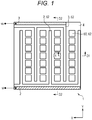
- Fig. 1 is a view illustrating a structure of a moisture detection element 1 according to this embodiment.
- Figs. 2A and 2B are views for explaining a principle that the moisture detection element 1 according to this embodiment detects moisture.
- Fig. 2A is a schematic cross-sectional view illustrating the principle of the moisture detection element 1 before moisture adhesion
- Fig. 2B is a schematic sectional view illustrating the principle of the moisture detection element 1 after moisture adhesion.
- Fig. 2C is a schematic cross-sectional view illustrating the state of the moisture detection element 1 to which dust 12 adheres.
- Figs. 2A to 2C are schematic cross-sectional views taken along line D1-D1 of Fig. 1 .
- Fig. 2D is a schematic cross-sectional view taken along line D2-D2 of Fig. 1 .
- the moisture detection element (moisture detection part) 1 is connected to a power supply 5 (see Figs. 2A and 2B ) and includes an application electrode (application part) 2, a detection electrode (output part) 3, an auxiliary electrode 60, and an insulating substrate 4.
- the application electrode 2 is an electrode to which an AC voltage vi is applied by the power supply 5.
- the detection electrode 3 is an electrode that detects an (alternating current) output voltage (voltage signal) vo when moisture is detected.
- the insulating substrate 4 is configured by a hydrophilic insulating substrate. Specifically, at least the surface is configured by an oxide such as an insulating metal oxide. Incidentally, the shape of the insulating substrate 4 may not be a substrate shape.
- the application electrode 2 and the detection electrode 3 have a comb shape.
- the application electrode 2 and the detection electrode 3 are installed separately on the insulating substrate 4 so as to be opposed to each other so that their comb teeth are engaged with each other. In this way, the area of a moisture adhesion part (reaction portion) can be enlarged, and a sensitivity can be improved.
- the auxiliary electrode 60 is installed between the application electrode 2 and the detection electrode 3.
- the auxiliary electrode 60 is installed on the insulating substrate 4 and is configured by a conductive film 61 which is a conductive film and an insulating film (insulation) 62 which is arranged on the conductive film 61 and is an insulating film.
- the insulating film 62 is formed only on the upper surface of the conductive film 61 and is not formed on the side surface of the conductive film 61.
- the conductive film 61 is not electrically connected to the application electrode 2 or the detection electrode 3. That is, the conductive film 61 is electrically insulated (independent) from the application electrode 2 and the detection electrode 3. Further, as illustrated in Figs. 1 , 2A, and 2D , the insulating film 62 is also arranged on part of the application electrode 2 and the detection electrode 3. Here, as illustrated in Figs. 2A and 2D , the insulating film 62 is formed only on the upper surfaces of the application electrode 2 and the detection electrode 3 and is not formed on side surfaces of the application electrode 2 and the detection electrode 3.
- the place where the insulating film 62 is arranged is a place where a short circuit may occur due to the adhesion of the dust 12. In this way, the amount of the insulating film 62 can be reduced, and the cost can be reduced.
- the insulating film 62 is configured by a metal oxide film, polyimide, resin, or the like.
- the capacitance humidity sensor described in JP 2011-53049 A is intended to measure humidity in the air.
- the moisture detection element 1 according to this embodiment is intended for detection of exhalation at a high humidity (substantially saturated state). Therefore, the moisture detection element 1 of this embodiment is not intended to measure the amount of moisture in the air, but only needs to be able to detect high humidity air (exhalation).
- the detection electrode 3 and the application electrode 2 are energized with the water molecules 11 and the conductive film 61 as a path. Then, the AC voltage vi applied from the detection electrode 3 to the application electrode 2 is detected (output).
- the moisture detection element 1 detects moisture on the basis of the detected (output) voltage (output voltage vo).
- the output voltage vo is an AC voltage.
- the moisture detection element 1 only needs to have the insulating substrate 4 that is wide enough to allow the water molecules 11 to adhere thereto, and can be reduced in size.
- the output voltage vo is almost 0 before moisture (water molecule 11) adheres to the insulating substrate 4, whereas the output voltage vo is almost the same as the AC voltage vi (theoretically) after the adhesion of moisture (water molecule 11). Accordingly, an excellent signal/noise (S/N) ratio can be realized.
- the surface of the insulating substrate 4 has an uneven structure as illustrated in Figs. 2A and 2B .
- the surface of the insulating substrate 4 has unevenness, and thus the surface area of the insulating substrate 4 can be increased. That is, since the surface of the insulating substrate 4 has unevenness, more water molecules 11 can be attached. Accordingly, the output voltage vo can be increased, and high sensitivity can be achieved.
- the highly hydrophilic oxide is an insulating metal oxide. That is, an oxygen atom is arranged on the surface.
- the moisture detection element 1 according to this embodiment uses the AC voltage vi as an applied voltage as illustrated in Fig. 2A and the like.
- the moisture detection element 1 according to this embodiment can be speeded up. That is, when a DC voltage is used as the applied voltage, the rise of the voltage is delayed due to the capacitor component in the equivalent circuit in the moisture detection element 1 and moisture. Further, this causes a detection delay.
- the AC voltage vi is used as the applied voltage, the influence of the capacitor component in the equivalent circuit is reduced, so that the detection delay is reduced.
- the detection can be speeded up by using a radio frequency (several MHz scale) as the frequency of the AC voltage vi as the applied voltage.
- Fig. 2C is a view illustrating an aspect in which the dust 12 adheres to the moisture detection element 1.
- Figs. 3A to 3C are views illustrating an example of the width of the insulating film 62 in the auxiliary electrode 60.
- Fig. 3A it is satisfied that the width of the conductive film 61 > the width of the insulating film 62.
- W2 ⁇ 2 may be about 10% or less of W1.
- Fig. 3B illustrates an example in which the width of the conductive film 61 is equal to the width of the insulating film 62.
- Fig. 3C illustrates an example in which it is satisfied that the width of the conductive film 61 ⁇ the width of the insulating film 62.
- FIGs. 3A to 3C illustrate the relationship between the width of the conductive film 61 and the width of the insulating film 62.
- the relationship between the width of the application electrode 2 and the width of the insulating film 62, and the relationship between the detection electrode 3 and the width of the insulating film 62 is the same.
- a conductive film 61 which is insulated from the application electrode 2 and the detection electrode 3 is arranged between the application electrode 2 and the detection electrode 3.
- the area of the portion to which moisture adheres is reduced, and the application electrode 2 and the detection electrode 3 are electrically connected even with a small amount of moisture.
- the insulating film 62 is provided, and thus the application electrode 2 and the detection electrode 3 are not conducted even if the dust 12 is deposited on the auxiliary electrode 60.
- Fig. 4 is an enlarged view of a part of the moisture detection element 1 illustrated in Fig. 1 .
- a illustrated in Fig. 4 denotes a distance between the application electrode 2 and the detection electrode 3 (this distance is referred to as an interelectrode distance), and it is desirable that a ⁇ 20 ⁇ m. Incidentally, most of the dust 12 in the atmosphere is 20 ⁇ m or less.
- distances b between the auxiliary electrode 60 (conductive film 61) and the application electrode 2 and between the auxiliary electrode 60 and the detection electrode 3 may be any distance.
- Fig. 5 is a table showing the relationship between the interelectrode distance and the output voltage vo.
- the interelectrode distance is the interelectrode distance a in Fig. 4 .
- This table shows the results of the following processing. First, the application electrode 2 and the detection electrode 3 were electrically connected to the moisture detection element without the auxiliary electrode 60 (conductive film 61) and the moisture detection element 1 with the auxiliary electrode 60, with saturated water vapor. Then, the AC voltage vi having a peak voltage of 3 V is applied to the application electrode 2. The table shows the output voltage vo detected by the detection electrode 3 as a result. It is shown that the higher the value of the output voltage vo, the better the sensitivity.
- the moisture detection element 1 according to this embodiment, it is possible to maintain excellent detection sensitivity while suppressing the occurrence of errors due to the dust 12. That is, the robustness of the moisture detection element 1 is improved.
- the moisture detection element 1 illustrated in Fig. 1 can be reduced in size, and it is not necessary to apply a large voltage. Thus, it is possible to realize low power consumption.
- the insulating film 62 is provided on the conductive film 61, the application electrode 2, and the detection electrode 3. In this way, for example, even if the dust 12 of 20 ⁇ m or more adheres to the application electrode 2 and the detection electrode 3 as illustrated in Fig. 2C , the occurrence of errors due to the dust 12 can be reduced.
- Fig. 6 is a view illustrating an example of a moisture detection element 1a provided with a heater 8.
- the heater 8 is provided between an insulating substrate 4a (4) and an insulating substrate 4b (4).
- the insulating substrates 4a and 4b may be made of the same material or different materials as long as they have insulating properties.
- the heater 8 is sandwiched between the insulating substrate 4a and the insulating substrate 4b.
- the invention is not limited thereto, and the heater 8 may be installed on the lower surface of the insulating substrate 4.
- Fig. 7A is a graph showing a relationship between the number of divisions of the auxiliary electrodes 60 and an error occurrence frequency.
- a horizontal axis indicates the number of divisions of the auxiliary electrodes 60
- a vertical axis indicates the error occurrence frequency.
- the number of divisions is the number of divisions in the Y direction in Fig. 1 .
- the number of divisions is "7".
- the graph L2 indicates the error occurrence frequency in the moisture detection element 1 including the insulating film 62.
- the error occurrence frequency can be reduced significantly compared to the moisture detection element not including the insulating film 62.
- the application electrode 2, the conductive film 61, and the detection electrode 3 may be short-circuited.
- the insulating film 62 is provided, as illustrated in Fig. 2C , it is possible to prevent the application electrode 2, the conductive film 61, and the detection electrode 3 from being short-circuited.
- the error occurrence frequency decreases as the number of divisions of the auxiliary electrode 60 increases.
- the application electrode 2 and the auxiliary electrode 60 may be short-circuited by one dust 12
- the detection electrode 3 and the auxiliary electrode 60 are short-circuited by another dust 12
- the application electrode 2 and the detection electrode 3 may be short-circuited.
- Fig. 7A shows the result obtained when forty moisture detection elements 1 having each division number of auxiliary electrodes 60 are used. The same applies to Figs. 7B and 7C described below. Further, in Fig. 7A , error detection is performed for one year for the moisture detection element 1 having each division number of the auxiliary electrodes 60, and the error occurrence frequency for each moisture detection element 1 is calculated.
- Fig. 7B is a graph showing a relationship between a condensation removal time after the heater 8 is turned on and the number of divisions of the auxiliary electrode 60.
- a horizontal axis indicates the number of divisions of the auxiliary electrode 60
- a vertical axis indicates the condensation removal time after the heater 8 is turned on.
- the heater 8 is set to be 40°C.
- the condensation removal time is shortened as the number of divisions of the auxiliary electrode 60 increases. This is because the surface area of each auxiliary electrode 60 is small. In addition, as the number of divisions of the auxiliary electrode 60 is increased, moisture is uniformly evaporated from the surface of the auxiliary electrode 60.
- Fig. 7C is a graph showing a relationship between a temperature recovery time after the heater 8 is turned off and the number of divisions of the auxiliary electrode 60.
- the temperature recovery time is a time until the surface of the insulating substrate 4 heated by the heater 8 is sufficiently cooled. Specifically, the time is a time until the insulating substrate 4 is cooled to room temperature (25°C) after the insulating substrate 4 is sufficiently heated by the heater 8 set to 40°C.
- a horizontal axis indicates the number of divisions of the auxiliary electrode 60
- a vertical axis indicates the temperature recovery time after the heater 8 is turned off.
- the temperature recovery time is shortened as the number of divisions of the auxiliary electrode 60 increases. This is because, as in Fig. 7B , the surface area of one auxiliary electrode 60 is small.
- the error occurrence frequency due to the adhesion of dust 12 can be reduced.
- Figs. 7B and 7C by dividing the auxiliary electrode 60, the heat capacity in one auxiliary electrode 60 is reduced, and the time for heat absorption and radiation is shortened. Accordingly, the re-measurement waiting time can be shortened, and the measurement efficiency can be improved.
- Figs. 8A to 8E are views illustrating a method for manufacturing the moisture detection element 1a according to this embodiment.
- Figs. 8A to 8E illustrate the method of manufacturing the moisture detection element 1a.
- the moisture detection element 1 illustrated in Figs. 1 and 2A also can be manufactured by the same method.
- Figs. 8A to 8E illustrate the portion comparable to the D2-D2 cross section of Fig. 1 .
- the application electrode 2, the detection electrode 3, and the conductive film 61 are formed on the insulating substrate 4a so as to have a shape as illustrated in Fig. 1 ( Fig. 8A ).
- the insulating substrates 4a and 4b include a transparent insulating material such as quartz glass, polyimide, transparent plastic, or transparent metal oxide.
- the heater 8 also includes a transparent member such as a transparent film heater (transparent conductive film).
- the application electrode 2, the detection electrode 3, and the conductive film 61 are formed on the insulating substrate 4a so as to have a shape as illustrated in Fig. 1 , which is referred to as a moisture detection element preparation F1.
- the application electrode 2, the detection electrode 3, and the conductive film 61 include an opaque metal member.
- a positive-type insulating photosensitive material P is applied in which portion exposed on the surface of the application electrode 2, the detection electrode 3, and the conductive film 61 of the moisture detection element preparation F1 is solubilized ( Fig. 8B ).
- Examples of the positive-type insulating photosensitive material P in which the exposed portion is solubilized include photosensitive polyimide.
- the back side of the moisture detection element preparation F1 is the side on which the application electrode 2, the detection electrode 3, and the conductive film 61 are not formed.
- the insulating substrates 4a and 4b and the heater 8 are transparent, and the application electrode 2, the detection electrode 3 and the conductive film 61 are opaque, the application electrode 2, the detection electrode 3 and the conductive film 61 serve as a mask. As a result, as illustrated in Fig. 8D , the portion of the insulating photosensitive material P that is not applied on the application electrode 2, the detection electrode 3, and the conductive film 61 becomes soluble (portion M).
- a photomask is formed in a portion other than the wiring connection portion (not illustrated) of the application electrode 2 and the detection electrode 3.
- the surface side is the side on which the application electrode 2, the detection electrode 3, and the conductive film 61 are formed.
- the wiring connection portion is a portion where the wiring is connected in the application electrode 2 and the detection electrode 3.
- the insulating film 62 cannot be formed on the places where the wiring is connected in the application electrode 2 and the detection electrode 3. In other words, the place where the wiring is connected in the application electrode 2 and the detection electrode 3 is exposed, and the wiring can be connected to the application electrode 2 and the detection electrode 3.
- the insulating photosensitive material P (reference numeral M1 in Fig. 8D ). Then, by washing away the soluble insulating photosensitive material P, the insulating photosensitive material P (that is, insulating film 62) is formed on the application electrode 2, the detection electrode 3, and the conductive film 61 as illustrated in Fig. 8E .
- the moisture detection element 1a having the insulating film 62 can be manufactured with high accuracy by a simple method.
- the manufacturing method is not limited to the manufacturing method illustrated in Figs. 8A to 8E , and the insulating film 62 may be formed by general photolithography. That is, the moisture detection elements 1 and 1a may be manufactured by resist formation ⁇ surface exposure using a photomask ⁇ development ⁇ etching (or processing). In this case, the heater 8 and the insulating substrate 4 need not be transparent members.
- the insulating film 62 includes a metal oxide film, the insulating film 62 is formed by such general photolithography.
- Fig. 9 is a view illustrating a basic configuration example of the exhalation sensor 100 having a planar arrangement structure.
- the moisture detection element 1 is arranged on a circuit board having a planar structure. Furthermore, in the exhalation sensor 100a, a plurality of types of small gas sensors (gas detection part) 101 are arranged around the moisture detection element 1.
- the moisture detection element 1 is illustrated in any of Figs. 1 and 6 and Figs. 24A to 28B described later.
- the gas sensor 101 arranged around the moisture detection element 1 is a gas sensor 101c for alcohol, a gas sensor 101d for acetaldehyde, a gas sensor 101f for hydrogen, and the like.
- a gas sensor 101c for alcohol a gas sensor 101c for alcohol
- a gas sensor 101d for acetaldehyde a gas sensor 101f for hydrogen
- hydrogen a gas sensor 101f for hydrogen
- the gas sensor 101c for alcohol detects whether the subject is drunk (presence/absence of alcohol in exhalation) and the like.
- the gas sensor 101d for acetaldehyde detects drunkenness by detecting a metabolite of alcohol
- the gas sensor 101f for hydrogen detects the presence or absence of activation of the digestive system.
- predetermined amount or more of a component is included in the exhalation.
- the moisture detection element 1 and the gas sensors 101c, 101d, and 101f do not have to be arranged as illustrated in Fig. 9 .
- the moisture detection element 1 is arranged as close to the center of the exhalation sensor 100a as possible.
- Fig. 10 is a view illustrating a configuration example of the exhalation sensor 100 for healthcare having a planar arrangement structure.
- the same components as those in Fig. 9 are denoted by the same reference numerals, and the description is omitted.
- the moisture detection element 1 is arranged at the center of the circuit board having a planar structure. Furthermore, in the exhalation sensor 100b, a plurality of types of small gas sensors (gas detection parts) 101 are arranged around the moisture detection element 1.
- the moisture detection element 1 is illustrated in any of Figs. 1 and 6 and Figs. 24A to 28B described later.
- the gas sensor 101 arranged around the moisture detection element 1 includes a gas sensor 101a for carbon monoxide, a gas sensor 101b for nitric oxide, a gas sensor 101c for alcohol, a gas sensor 101d for acetaldehyde, a gas sensor 101e for acetone, and a gas sensor 101f for hydrogen, a gas sensor 101g for hydrogen sulfide, a gas sensor 101h for ammonia, and the like.
- a gas sensor 101a for carbon monoxide a gas sensor 101b for nitric oxide
- a gas sensor 101c for alcohol
- a gas sensor 101d for acetaldehyde
- a gas sensor 101e for acetone
- a gas sensor 101f for hydrogen
- a gas sensor 101g for hydrogen sulfide for ammonia
- the moisture detection element 1 and the gas sensors 101a to 101h need not be arranged as illustrated in Fig. 10 . However, it is preferable that the moisture detection element 1 be arranged as close to the center of the exhalation sensor 100b as possible.
- the gas sensor 101a for carbon monoxide can detect the presence or absence of smoking
- the gas sensor 101b for nitric oxide can detect the presence or absence of inflammation in the respiratory system such as pneumonia
- the gas sensor 101e for acetone can detect the presence or absence of diabetes
- the gas sensor 101g for hydrogen sulfide can detect the presence or absence of bad breath
- the gas sensor 101h for ammonia can detect the presence or absence of Helicobacter pylori or liver disease.
- preence or absence refers to whether or not a predetermined amount or more of a component is included in the exhalation.
- the configuration includes eight types of gas sensors 101 but does not have to include all of them.
- a configuration including one type or several types of gas sensors 101 may be used depending on the purpose.
- the used gas sensor 101 may be switched according to the purpose.
- the invention is not limited to the gas sensor 101 used in the example illustrated in Fig. 10 .
- a gas sensor 101 for carbon dioxide may be arranged.
- gas detection can be performed while determining whether or not the exhalation introduced by the moisture detection element 1 is human exhalation as will be described later.
- Fig. 11A is a schematic cross-sectional view of an exhalation sensor package (hereinafter referred to as a package 200a) using wire bonding.
- the package 200a has a box-shaped main body 201 and a lid 202.
- the exhalation sensor 100 is installed inside the ceramic main body 201.
- the main body 201 includes an outer application electrode 211 and an outer detection electrode 212 on the outside.
- the main body 201 has an inner application electrode 221 and an inner detection electrode 222 on the inside.
- the outer application electrode 211 and the inner application electrode 221 are connected by a main body wiring 231 built in the main body 201.
- the outer detection electrode 212 and the inner detection electrode 222 are connected by the main body wiring 231 built in the main body 201.
- the inner application electrode 221 is connected to the application electrode 2 (see Figs. 1 to 2B and the like) of the moisture detection element 1 by wire bonding using the conductive wire 232 and wiring on the circuit board of the exhalation sensor 100.
- the inner detection electrode 222 is connected to the detection electrode 3 (see Figs. 1 to 2B and the like) of the moisture detection element 1 by wire bonding using the conductive wire 232 and wiring on the circuit board of the exhalation sensor 100.
- the lid 202 is provided with a mesh and prevents the dust 12 and the like existing outside the package 200a from adhering to the moisture detection element 1.
- a mesh is provided in the lid 202 as above, the dust 12 can be prevented from adhering to the moisture detection element 1, and the occurrence of errors due to the dust 12 is further reduced.
- Fig. 11B is a schematic cross-sectional view of an exhalation sensor package (hereinafter referred to as a package 200b) using a flip chip.
- the package 200b includes a box-shaped main body 201b and a lid 202.
- the main body 201b further includes a side wall 203 and a bottom 204. Both the side wall 203 and the bottom 204 are made of ceramic. Incidentally, as illustrated in Fig. 11B , the side wall 203 also serves as a leg.
- the exhalation sensor 100 is installed so as to be placed on the bottom 204.
- the side wall 203 includes the outer application electrode 211 and the outer detection electrode 212 on the outside.
- the side wall 203 includes the inner application electrode 221 and the inner detection electrode 222 on the inside.
- the outer application electrode 211 and the inner application electrode 221 are connected by the main body wiring 231 built in the side wall 203.
- the outer detection electrode 212 and the inner detection electrode 222 are connected by the main body wiring 231 built in the side wall 203.
- the inner application electrode 221 is connected to an application terminal (not illustrated) on the circuit board of the exhalation sensor 100 in a flip-chip format. This application terminal is connected to the application electrode 2 (see Fig. 1 and 2A and the like) of the moisture detection element 1 via wiring on the circuit board of the exhalation sensor 100.
- the inner detection electrode 222 is connected to a detection terminal (not illustrated) on the circuit board of the exhalation sensor 100 in a flip chip format. This detection terminal is connected to the detection electrode 3 (see Fig. 1 and 2A and the like) of the moisture detection element 1 via the wiring on the circuit board of the exhalation sensor 100.
- the lid 202 is provided with a mesh. Since this mesh has the same configuration and effect as in Fig. 11A , the description thereof is omitted here.
- the lid 202 can be omitted in the packages 200a and 200b.
- Fig. 12 is a view illustrating an example of functional blocks of an exhalation test system Z according to this embodiment.
- the exhalation test system Z includes an exhalation detector 300, an analysis device (analysis part) 500, a transmission device 601, and a storage device 602.
- the exhalation detector 300 includes an exhalation sensor 100 and a measurement control device 400.
- the exhalation sensor 100 includes the moisture detection element 1 and the gas sensor 101. However, since the description has been given in Figs. 9 and 10 , the description thereof is omitted here.
- the measurement control device 400 converts the frequency of the AC power supply 410 (see Fig. 13 ) and outputs it.
- the exhalation detector 300 converts the acquired analog signal into a digital signal by A/D (Analog/Digital) converters 301a and 301b and outputs the digital signal to the analysis device 500.
- the acquired analog signal is a voltage signal of the output voltage vo acquired from the moisture detection element 1 or a detection signal acquired from the gas sensor 101.
- the analysis device 500 acquires a voltage signal of the output voltage vo from the moisture detection element 1 in the exhalation sensor 100 and acquires a detection signal from the gas sensor 101. Then, the analysis device 500 analyzes the gas content rate in the exhalation on the basis of the output voltage vo acquired from the moisture detection element 1, the detection signal acquired from the gas sensor 101, and the like. Incidentally, in this embodiment, the analysis device 500 acquires the output voltage vo and the detection signal from the exhalation sensor 100. However, the invention is not limited thereto.
- the measurement control device 400 may acquire the output voltage vo and the detection signal from the exhalation sensor 100 and transfer the acquired output voltage vo and the detection signal to the analysis device 500.
- the storage device 602 is a database server or the like.
- the storage device 602 holds the output voltage vo acquired by the analysis device 500 from the moisture detection element 1 and the detection signal acquired from the gas sensor 101 together with the test time or holds the analysis result by the analysis device 500.
- the transmission device 601 notifies the analysis result (such as information about the driver state) by the analysis device 500 to a central information center (not illustrated) or the like.
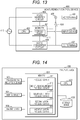
- Fig. 13 is a functional block view illustrating a configuration example of the measurement control device 400 used in this embodiment.
- the measurement control device 400 includes a memory 401, a central processing unit (CPU) 402, an input device 403, and an AC/AC inverter circuit 404. Further, the measurement control device 400 includes an AC terminal 405, an AC/DC converter circuit 406, and a DC terminal 407.
- CPU central processing unit
- AC/AC inverter circuit 404 Further, the measurement control device 400 includes an AC terminal 405, an AC/DC converter circuit 406, and a DC terminal 407.
- a control part 411 is embodied by executing a program by the CPU 402.
- the control part 411 sends an instruction to the AC/AC inverter circuit 404 and the AC/DC converter circuit 406 on the basis of the information input via the input device 403.
- the AC/AC inverter circuit 404 converts the frequency and voltage of the AC voltage input from the AC power supply 410 on the basis of the instruction sent from the control part 411 and outputs the converted voltage to the AC terminal 405.
- the moisture detection element 1 is connected to the AC terminal 405.
- the AC/DC converter circuit 406 converts the voltage of the AC voltage input from the AC power supply 410 on the basis of the instruction sent from the control part 411 and further converts the alternating current into a direct current to output the direct current to the DC terminal 407.
- the gas sensor 101 (see Fig. 12 ) is connected to the DC terminal 407.
- the output of the AC/DC converter circuit 406 is connected via a switch 408 to an adder 409 provided on the output side of the AC/AC inverter circuit 404.
- the opening and closing of the switch 408 is controlled by the control part 411. Prior to the introduction of exhalation, the switch 408 is in an ON state. At this time, when the potential difference between the DC voltage Vi applied to the moisture detection element 1 and the output voltage Vo is equal to or less than a predetermined value (S202 in Fig. 17 ⁇ Yes), the voltage in which the DC voltage is biased to the AC voltage with the switch 408 turned ON is applied to the application electrode 2 for a predetermined time.
- a predetermined value is a case where condensation occurs (details will be described later).
- the switch 408 is in an OFF state.
- the output voltage of the DC terminal 407 may be directly applied to the moisture detection element 1.
- the configuration of the measurement control device 400 illustrated in Fig. 13 is an example and is not limited to the configuration illustrated in Fig. 13 .
- an AC signal (AC voltage vi) may be generated using a crystal oscillator.
- the measurement control device 400 illustrated in Fig. 13 corresponds to the power supply 5 in Figs. 2A and 2B .
- Fig. 14 is a functional block view illustrating a configuration example of the analysis device 500 used in this embodiment.
- the analysis device 500 is, for example, a personal computer (PC), and includes a memory 501, a CPU 502, a transmission/reception device 503, and a display device (display part) 504. Furthermore, the analysis device 500 includes a storage device 505 such as a hard disk drive (HDD), an imaging device (imaging part) 506, and the like. Incidentally, the imaging device 506 can be omitted when the spoofing prevention processing described later is not performed.
- a storage device 505 such as a hard disk drive (HDD), an imaging device (imaging part) 506, and the like.
- the imaging device 506 can be omitted when the spoofing prevention processing described later is not performed.
- a program stored in the storage device 505 is loaded into the memory 501. Then, the loaded program is executed by the CPU 502, thereby realizing a processing part 511 and parts 512 to 515 configuring the processing part 511.
- a moisture measurement processing part 512 performs processing related to the measurement of moisture contained in exhalation on the basis of the detection signal sent from the moisture detection element 1 (see Fig. 12 ).
- a gas measurement processing part 513 performs processing related to measurement of various gases contained in exhalation on the basis of the detection signal sent from the gas sensor 101 (see Fig. 12 ).
- a determination processing part 514 determines, for example, whether or not the subject is drunk.
- An authentication processing part 515 performs spoofing prevention processing described later.
- the gas measurement processing part 513 can be omitted.
- the exhalation detector 300, the analysis device 500, the transmission device 601, and the storage device 602 are separate devices, but the invention is not limited to this.
- at least two of the exhalation detector 300, the analysis device 500, the transmission device 601, and the storage device 602 may be one device.
- the exhalation detector 300, the analysis device 500, the transmission device 601, and the storage device 602 may all be provided in one device.
- the analysis device 500, the transmission device 601, and the storage device 602 may be provided in one device.
- Fig. 15 is a flowchart showing the procedure of the exhalation detection processing performed in this embodiment.
- the exhalation test system Z performs a condensation removal processing (S102).
- the condensation removal processing will be described later.
- the moisture measurement processing part 512 displays a screen (exhalation introduction request screen) for prompting the user to introduce exhalation on the display device 504 (S103).
- exhalation introduction is started (S105).
- the moisture measurement processing part 512 starts measuring the output voltage vo from the moisture detection element 1, whereby the moisture measurement is started (S106). At this time, the moisture measurement processing part 512 calculates the difference in voltage value from time 0 to the current time as the output voltage vo.
- the moisture measurement processing part 512 determines whether or not the output voltage vo from the moisture detection element 1 is equal to or higher than the first threshold value vth1 (S111).
- step S111 when the output voltage vo from the moisture detection element 1 is less than the first threshold value vth1 (S111 ⁇ No), it is assumed that the exhalation intensity is insufficient, and the introduction of exhalation is continued in the subject (S112). Then, the moisture measurement processing part 512 returns the process to step S111.
- step S111 when the output voltage vo is equal to or higher than the first threshold value vth1 (S111 ⁇ Yes), the moisture measurement processing part 512 determines whether or not the output voltage vo from the moisture detection element 1 is equal to or higher than the second threshold value vth2 (S113). Incidentally, it is satisfied that first threshold value vth1 ⁇ second threshold value vth2. Further, the output voltage vo is actually an AC voltage, and thus the determination in step S112 is performed when the moisture measurement processing part 512 determines whether or not the number of times that the voltage peak of the output voltage vo is equal to or greater than the second threshold value vth2 exceeds a predetermined number of times. This will be described later.
- step S113 when the output voltage vo is less than the second threshold value vth2 (S113 ⁇ No), it is assumed that the exhalation intensity is insufficient, and the moisture measurement processing part 512 continues the introduction of exhalation to the subject (S114). Then, the moisture measurement processing part 512 returns the process to step S113.
- step S113 when the output voltage vo is equal to or higher than the second threshold value vth2 (S113 ⁇ Yes), the moisture measurement processing part 512 determines that the exhalation intensity is sufficient (S121). Thereafter, the subject ends the introduction of exhalation (S122). At this time, the exhalation detector 300 notifies the subject that the introduction of exhalation is to be terminated by a buzzer, sound, screen display, or the like.
- Fig. 16 is a graph illustrating the time change of the output voltage vo of the moisture detection element 1.
- a horizontal axis represents time (sec)
- a vertical axis represents output voltage vo (arbitrary unit).
- the output voltage vo starts to increase, and at time t11, the output voltage vo exceeds the first threshold value vth1 (step S111 in Fig. 15 ; Yes). Thereafter, the output voltage vo continues to increase, and the voltage peak exceeds the second threshold value vth2 fifteen times at time t12 (step S113 in Fig. 15 ; Yes).
- the number of times can be arbitrarily determined. The number of times depends on the frequency, but the number of peaks is approximately equivalent to one to three seconds after the output voltage vo exceeds the first threshold value vth1.
- the second threshold value vth2 is an output voltage vo sufficient to confirm that moisture is contained in the introduced air (exhalation).
- Fig. 17 is a flowchart illustrating the procedure of condensation removal processing (S102 in Fig. 15 ) performed in this embodiment.
- the DC voltage Vi is applied to the application electrode 2 (S201), and the moisture measurement processing part 512 is configured to measure the output voltage (DC) Vo at the detection electrode 3.
- the DC voltage Vi applied in step S201 is a voltage output from the AC terminal 405 of the measurement control device 400.
- the voltage actually applied in step S201 is obtained by biasing a DC voltage to an AC voltage as described above.
- the moisture measurement processing part 512 determines whether or not Vi-Vo is less than the third threshold value Vth3 (S202). In addition, Vi and Vo indicate bias voltage values.
- step S202 when Vi-Vo is greater than or equal to the third threshold value Vth3 (S202 ⁇ No), the moisture measurement processing part 512 determines that no condensation has occurred or that condensation is removed, and the procedure returns to the processing in Fig. 15 .
- step S202 when Vi-Vo is less than the third threshold value Vth3 (S202 ⁇ Yes), the moisture measurement processing part 512 determines that condensation occurs.
- the moisture measurement processing part 512 determines whether or not the number of times of application n is greater than the predetermined number N (S203).
- step S203 when the number n of times of application is larger than the predetermined number N (S203 ⁇ Yes), the moisture measurement processing part 512 gives an error notification (S204).
- the error notification information indicating that an error is detected may be displayed on the display device 504, or the error notification may be issued from an alarm device (not illustrated). After the error notification, the exhalation test system Z ends the processing.
- step S203 when the number n of application is equal to or less than the predetermined number N (S203 ⁇ No), the moisture measurement processing part 512 applies a direct current to the moisture detection element 1 for a certain period of time (S205).
- step S205 an alternating current biased with a direct current is actually applied.
- the moisture measurement processing part 512 adds 1 to n (n ⁇ n + 1) (S206), and the procedure returns to step S201.
- the direct current corresponding to the bias flows through the water molecules 11 and the conductive film 6, and the water molecules 11 are evaporated by Joule heat generated at that time. In this way, the condensation can be removed.
- the path of the water molecule 11 is regarded as a current path, and by passing a direct current through this path, the water molecule 11 is evaporated by Joule heat derived from the resistance of the water molecule 11.
- Figs. 18A and 18B are flowcharts illustrating a procedure of the gas detection processing performed in this embodiment.
- the processing illustrated in Figs. 18A and 18B the processing illustrated in Fig. 15 is used.
- Figs. 18A and 18B illustrate a case where the gas to be detected is alcohol, but gases other than alcohol can also be detected by the same procedure.
- acetaldehyde which is a metabolite, and hydrogen, with a high concentration of about 10 ppm in the exhalation, are subject to gas measurement. Then, the alcohol gas concentration is calculated on the basis of the gas concentrations of alcohol, acetaldehyde, and hydrogen.
- the gas sensor 101c for alcohol the gas sensor 101d for acetaldehyde, and the gas sensor 101f for hydrogen are used as the gas sensor 101.
- each gas sensor 101 of the gas sensor 101c for alcohol, the gas sensor 101d for acetaldehyde, and the gas sensor 101f for hydrogen is referred to as gas sensors 101c, 101d, and 101f, respectively.
- the same step numbers are assigned to the same processing as those in Fig. 15 .
- steps S101 to S112 in Fig. 18A are the same as the processing of steps S101 to S112 in Fig. 15 , and thus the description thereof is omitted here.
- step S111 when the output voltage vo is equal to or higher than the first threshold value vth1 (S111 ⁇ Yes), the gas measurement processing part 513 starts output measurement (gas measurement) from the gas sensors 101c, 101d, and 101f (S301).
- step S113 the moisture measurement processing part 512 performs the processing of step S113.
- the processing in steps S113 to S122 is the same as the processing in steps S113 to S122 in Fig. 15 , and thus description thereof is omitted here.
- step S122 the exhalation introduction is completed, and the gas measurement processing part 513 ends the output measurement (gas measurement) from the gas sensors 101c, 101d, and 101f (S311).
- the gas measurement processing part 513 calculates the gas saturation signal values of the gas sensors 101c, 101d, and 101f from the output curves from the output start to the output end from the gas sensors 101c, 101d, and 101f (S321). The processing of step S321 will be described later.
- the gas measurement processing part 513 calculates each gas concentration (saturated gas concentration) in a saturated state by the differential evolution method on the basis of the calculated gas saturation signal value (S322 in Fig. 18B ).
- Each gas is alcohol, acetaldehyde, hydrogen or the like. In this way, when the saturated gas concentration of a certain gas is calculated using the differential evolution method on the basis of a plurality of saturated gas concentrations, a highly accurate saturated gas concentration can be calculated.
- the determination processing part 514 determines whether or not the saturated gas concentration of alcohol (alcohol concentration) among the saturated gas concentrations calculated in step S322 is equal to or higher than a reference value (S323).
- step S323 when the alcohol concentration is less than the reference value (S323 ⁇ No), the determination processing part 514 determines that the subject is not drunk (S324).
- step S323 when the alcohol concentration is equal to or higher than the reference value (S323 ⁇ Yes), the determination processing part 514 determines that the subject is drunk (S325).
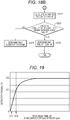
- Fig. 19 is a graph illustrating a time change of a detection signal output from the gas sensor 101.
- a vertical axis represents the detection signal (V)
- a horizontal axis represents the response time (sec) of the gas sensor 101.
- Time t11 in Fig. 19 is time t11 in Fig. 16 . That is, Fig. 19 illustrates that the output voltage vo from the moisture detection element 1 exceeds vth1 at time t11. Then, the gas measurement processing part 513 starts gas measurement at time t11 when the output voltage vo from the moisture detection element 1 exceeds vth1 (step S301 in Fig. 18A ). Incidentally, since the gas sensor 101 starts to react before the detection of the introduction of exhalation, time t11 is slightly on the + side from the origin.
- Time t12 in Fig. 19 is time t12 in Fig. 16 . That is, Fig. 19 illustrates that the detection signal reaches the value E1 at time t12, and the output voltage vo from the moisture detection element 1 exceeds vth2. Then, the gas measurement processing part 513 ends the gas measurement at time t12 (S311 in Fig. 18A ). Then, the gas measurement processing part 513 estimates a gas saturation signal value E2 on the basis of the value E1 of the detection signal from the gas sensor 101 at time t12. Incidentally, since the gas detection signal rises in a predetermined trend, a gas saturation signal value E2 can be estimated from time t11, time t12, and the detection signal value E1. The time from the start of exhalation introduction to the calculation of the gas saturation signal value E2 is about 3 seconds.
- a cover (not illustrated) is often provided around the sensor portion of the gas sensor 101.
- the space in the cover has the same concentration as the introduced gas even if the amount of gas introduced is small. That is, as the size of the space in the cover in the gas sensor 101 becomes smaller, the time until saturation becomes shorter. Therefore, when the size of the space in the cover in the gas sensor 101 is small, as illustrated in Fig. 19 , the gas saturation signal value E2 does not have to be estimated from the detection signal value E1. That is, the gas measurement processing part 513 may directly acquire the gas saturation signal value E2.
- the gas measurement processing part 513 waits for three to five seconds after the exhalation is introduced. Further, when the detection signal of the gas sensor 101c for alcohol to be measured reaches the peak value, the gas measurement processing part 513 acquires the detection signals of the gas sensor 101d for acetaldehyde and the gas sensor 101f for hydrogen. Then, the gas measurement processing part 513 performs concentration calculation based on the differential evolution method on the basis of the gas saturation signal values acquired directly from the respective gas sensors 101c, 101d, and 101f. Then, the gas measurement processing part 513 calculates an accurate gas saturation concentration of alcohol, acetaldehyde, and hydrogen.
- the time from time t11 to time t12 is about one to two seconds.
- the gas measurement can be performed with a measurement of about one to two seconds, and time can be greatly reduced.
- the exhalation test system Z using the moisture detection element 1 of this embodiment it is possible to test a gas (for example, alcohol) in a considerably short time. In particular, it is possible to determine whether or not the introduced exhalation is actually exhalation and to determine whether or not the subject is drunk in a short measurement time.
- a gas for example, alcohol
- Fig. 20 is a view illustrating an example (first example) of a mobile type exhalation test device 700a (700) .
- the exhalation test device (portable terminal) 700a illustrated in Fig. 20 has, for example, a business card size.
- the exhalation test device 700a includes an exhalation introduction port (exhalation introduction part) 701 and a display screen 702.
- An exhalation detector 300, an analysis device 500, a transmission device 601, and a storage device 602 illustrated in Fig. 12 are mounted inside the exhalation test device 700a.
- the display screen 702 corresponds to the display device 504 in Fig. 14 .
- the exhalation and gas are detected by the internal exhalation sensor 100. Then, a test result by the exhalation test device 700a is displayed on the display screen 702.
- the exhalation sensor 100 mounted in the exhalation test device 700a may be the exhalation sensor 100a illustrated in Fig. 9 or the exhalation sensor 100b illustrated in Fig. 10 .
- Fig. 21 is a view illustrating an example (second example) of a mobile type exhalation test device 700b.
- the exhalation test device (portable terminal) 700b (700) illustrated in Fig. 21 is of a type in which an exhalation introduction device 710 is attached to a smartphone 720.
- the exhalation introduction device 710 is connected to the smartphone 720 by, for example, a universal serial bus (USB) or the like.
- USB universal serial bus
- the exhalation detector 300 illustrated in Fig. 12 is mounted in the exhalation introduction device 710.
- the analysis device 500, the transmission device 601, and the storage device 602 are mounted on the smartphone 720 in the form of an application.
- the exhalation introduction device 710 is provided with an exhalation introduction port (exhalation introduction part) 711.
- the exhalation and gas are detected by the internal exhalation sensor 100 (see Fig. 12 ). Then, the result of the exhalation test performed on the smartphone 720 is displayed on the display screen 722 of the smartphone 720.
- the display screen 722 corresponds to the display device 504 in Fig. 14 .
- the exhalation introduction device 710 is provided with an opening 712 so as not to block a camera (imaging part) 721 of the smartphone 720 when attached to the smartphone 720.
- the camera 721 of the smartphone 720 can be used, and the spoofing prevention processing described later can be performed.
- the camera 721 corresponds to the imaging device 506 in Fig. 14 .
- the exhalation test device 700 such as the exhalation test device 700a illustrated in Fig. 20 and the exhalation test device 700b illustrated in Fig. 21 can be downsized.
- the exhalation test device 700a is downsized in this way, the exhalation test device can be used for home use or be attached to a bicycle, thereby providing a healthcare product that can be used easily.
- Fig. 22 is a view illustrating an example of an exhalation test device 700c which is provided in an automobile 801.
- the exhalation introduction device 730 is provided in the automobile 801.
- the exhalation detector 300 in Fig. 12 is mounted on the exhalation introduction device 730.
- the analysis device 500, the transmission device 601, and the storage device 602 are mounted on an engine control unit (ECU) (not illustrated).
- ECU engine control unit
- the exhalation introduction device 730 includes an exhalation introduction port (not illustrated).
- the exhalation and gas are detected by the internal exhalation sensor 100 (see Fig. 12 ) or the ECU. Further, when alcohol is detected, the ECU performs an interlock function to prevent starting an engine (not illustrated) or depressing the accelerator pedal, for example.
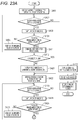
- Fig. 23A and Fig. 23B are flowcharts showing a procedure of spoofing prevention processing performed in this embodiment.
- Fig. 23A and Fig. 23B are the processing performed in the exhalation test system Z that can use the camera 721 as illustrated in Fig. 21 , for example.
- Fig. 23A and Fig. 23B are the processing performed before driving the automobile 801 (see Fig. 22 ).
- Fig. 14 is referred to as appropriate.
- the authentication processing part 515 of the analysis device 500 displays information (authentication button operation request screen) that prompts the user to operate the authentication button on the display device 504 (S401).
- the authentication processing part 515 determines whether or not the authentication button is operated (S402).
- the authentication button is a button displayed on the display screen 722 of the smartphone 720, and is operated by the user.
- the authentication button is a button displayed on a car navigation screen (not illustrated).
- the smartphone 720 and the analysis device 500 provided in the vehicle can communicate with each other by proximity communication or the like. Then, a detection signal of the moisture detection element 1, the gas sensor 101, and the like, a face image captured by the camera 721 as necessary, and the like are transmitted from the smartphone 720 to the analysis device 500 provided in the vehicle.
- step S402 when the authentication button is not operated (S402 ⁇ No), the authentication processing part 515 returns the process to step S401.
- step S402 when the authentication button is operated (S402 ⁇ Yes), the imaging device 506 captures a face image (S403).
- the face image captured at this time is referred to as a face image A.
- the authentication processing part 515 determines whether or not the captured face image A is a face image which can be authenticated (S404).
- the face image which can be authenticated is a face image that can be used for determining whether or not the subject is the same person as compared to a face image B that is captured later. Specifically, eyes, nose, mouth, outline, and the like are reflected.
- step S404 when the face image is not the face image which can be authenticated (S404 ⁇ No), the authentication processing part 515 displays information (re-imaging request screen) prompting re-imaging on the display device 504 (S405) and returns the process to step S402.
- step S404 when the face image is the face image which can be authenticated (S404 ⁇ Yes), the exhalation test system Z performs drinking determination processing by performing the processing starting from step S102 in Fig. 18A (S411).
- the authentication processing part 515 determines whether or not the subject is drunk using the result of the drinking determination processing in step S411 (S412).
- step S412 when the subject is drunk (S412 ⁇ Yes), the authentication processing part 515 displays information (driving-not-allowed screen) indicating that driving is not allowed on the display device 504 (S413).
- the exhalation test system Z when the exhalation test system Z is a system as illustrated in Fig. 22 , the exhalation test system Z may perform an interlock when the determination of "Yes" is made in step S412.
- the authentication processing part 515 stores the face image A (S414) and stores the result of step S411 (drinking determination result) in the storage device 505 (S415).
- step S412 when the subject is not drunk (S412 ⁇ No), the authentication processing part 515 displays the face image A and the result of drinking determination processing (drinking determination result) on the display device 504 (S421).
- the authentication processing part 515 displays information (authentication button operation request screen) that prompts the user to operate an authentication button (not illustrated) on the display device 504 (S422).
- the authentication button is the same as that displayed in step S402.
- the authentication processing part 515 determines whether or not the authentication button is operated (S423).
- step S423 when the authentication button is not operated (S423 ⁇ No), the authentication processing part 515 returns the process to step S422.
- step S423 when the authentication button is operated (S423 ⁇ Yes), the imaging device 506 captures a face image (S424).
- the face image captured at this time is referred to as a face image B.
- the authentication processing part 515 determines whether or not the captured face image B is the face image which can be authenticated (S425).
- the face image which can be authenticated is the same as that in step S404, and thus, the description thereof is omitted here.
- step S425 when the face image is not the face image which can be authenticated (S425 ⁇ No), the authentication processing part 515 displays information (re-imaging request screen) prompting re-imaging on the display device 504 (S426). Thereafter, the authentication processing part 515 returns the process to step S423.
- step S425 when the face image is the face image which can be authenticated (S425 ⁇ Yes), the authentication processing part 515 compares the face image A with the face image B. Accordingly, the authentication processing part 515 determines whether or not the face image A and the face image B are face images of the same person (S431 in Fig. 23B ).
- step S431 when face image A and face image B are face images of the same person (S431 ⁇ Yes), the authentication processing part 515 stores the face image A and the face image B in the storage device 505 (S432). Thereafter, the authentication processing part 515 stores the result (drinking determination result) of the drinking determination processing in step S411 in association with the face images A and B in the storage device 505 (S433) and ends the processing.
- step S431 when the face image A and face image B are not the face image of the same person (S431 ⁇ No), the exhalation test system Z performs the drinking determination processing again by performing the processing starting from step S102 of Fig. 18A (S441).
- the authentication processing part 515 determines whether or not the subject is drunk using the result of the drinking determination processing in step S441 (S442).
- step S442 when the subject is not drunk (S442 ⁇ No), the authentication processing part 515 stores the face image B in the storage device 505 (S432).
- authentication processing part 515 stores the result (drinking determination result) of drinking determination processing in step S422 in association with the face image B in storage device 505 (S433) and ends the processing.
- step S442 when the subject is drunk (S442 ⁇ Yes), the authentication processing part 515 displays information indicating that driving is not allowed (driving-not-allowed screen) on the display device 504 (S443).
- the exhalation test system Z when the exhalation test system Z is a system as illustrated in Fig. 22 , the exhalation test system Z may perform an interlock when the determination of "Yes" is made in step S442.
- the authentication processing part 515 stores the face image B (S444) and stores the result of step S441 (drinking determination result) in association with the face image B in the storage device 505 (S445).
- the authentication button depression in step S402 may be performed immediately before leaving the office or the like, and the authentication button depression in step S423 may be performed immediately before the accelerator pedal is depressed.
- the authentication processing part 515 may store the face image and the drinking determination result in association with the tachometer information. Even in the case of a general driver, the face image and the drinking determination result may be stored as evidence of the drinking test.
- the face image A before the exhalation introduction and the face image B after the exhalation introduction are compared to prevent drunk driving using spoofing.
- the face image A is a face image captured before boarding
- the face image B is a face image captured after boarding.
- Figs. 24A to 24C are views illustrating an example of a moisture detection element 1W having a low-temperature type and a high-temperature type.
- Fig. 24A illustrates a top view of the moisture detection element 1W.
- Fig. 24B is a schematic cross-sectional view taken along line B-B in Fig. 24A
- Fig. 24C is a schematic cross-sectional view taken along line C-C in Fig. 24A .
- the unevenness structure of the insulating substrate 4 can be distinguished into a low-temperature type used in a low-temperature environment (under an environment below a predetermined temperature) illustrated in Fig. 24B and a high-temperature type used in a high-temperature environment (under an environment above a predetermined temperature) illustrated in Fig. 24C .
- the low-temperature type moisture detection element 1f has a smaller unevenness on the insulating substrate 4f (4) than the high-temperature type moisture detection element 1g illustrated in Fig. 24C .
- the unevenness of the insulating substrate 4g (4) is made larger than in the low-temperature type illustrated in Fig. 24B .
- the low-temperature type moisture detection element 1f and the high-temperature type moisture detection element 1g are the same as the moisture detection element 1 illustrated in Figs. 1 to 2B except for the shape of the insulating substrate 4.
- the elements other than the insulating substrate 4 are denoted by the same reference numerals, and the description is omitted.
- the exhalation humidity decreases. For this reason, in the high-temperature type, as illustrated in Fig. 24C , the unevenness of the insulating substrate 4g is increased so that moisture (water molecules 11 (see Fig. 2A )) is easily attached. In this way, it is possible to provide the moisture detection element 1g that operates properly even in a high-temperature environment where the exhalation humidity is low.
- the AC voltage vi is applied from the power supply 5 to the low-temperature type moisture detection element 1f and the high-temperature type moisture detection element 1g.
- the moisture detection element 1W that can be used in either a low-temperature environment or a high temperature environment.
- the size of the unevenness of the insulating substrate 4 is two types of a low-temperature type and a high-temperature type, but may be three or more types. That is, the moisture detection element 1W having the insulating substrate 4 suitable for the intermediate temperature between the low-temperature type and the high-temperature type may be provided by increasing the unevenness as the low-temperature type changes to the high-temperature type.
- the low-temperature type moisture detection element 1f and the high-temperature type moisture detection element 1g may be switched in accordance with the ambient temperature.
- the unevenness of the insulating substrate 4 may have a mountain shape as illustrated in Figs. 24B and 24C .
- the invention is not limited thereto, and the unevenness may have, for example, a protrusion shape.
- the unevenness of the insulating substrate 4 may be formed in a shape such as a random shape other than a mountain shape or a protrusion shape.
- the size of the unevenness of the insulating substrate 4 is the difference between the height and depth of the unevenness and the size of the undulations.
- the height of the unevenness of the insulating substrate 4 is nano level, for example, about 1 nm to 100 nm.
- the conductive film 61 is assumed to be a metal, the conductive film 61 is not limited to a metal as long as it has conductivity.
- graphite or the like may be used as the conductive film 61.
- Figs. 25 to 28B illustrate a modification of the moisture detection element 1 according to this embodiment.
- the same components as those in Figs. 1 and 2A are denoted by the same reference numerals as those in Figs. 1 and 2A .
- Fig. 25 is a view illustrating a first modification of the moisture detection element 1 according to this embodiment.
- a moisture detection element 1b illustrated in Fig. 25 includes an auxiliary electrode 60b divided between the application electrode 2 and the detection electrode 3 in a strip shape in the vertical direction (Y direction).
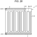
- Fig. 26 is a view illustrating a second modification of the moisture detection element 1 according to this embodiment.
- a moisture detection element 1c illustrated in Fig. 26 includes one auxiliary electrode 60c between the application electrode 2 and the detection electrode 3.
- Fig. 27 is a view illustrating a third modification of the moisture detection element 1 according to this embodiment.
- the shape of the auxiliary electrode 60d does not have the same shape between the application electrode 2 and the detection electrode 3.
- Figs. 28A and 28B are views illustrating a fourth modification of the moisture detection element 1 in this embodiment.
- the auxiliary electrode 60 of the moisture detection element 1 in Fig. 1 is omitted.
- the auxiliary electrode 60 is omitted, if the insulating film 62 is formed on the application electrode 2 and the detection electrode 3, the occurrence of errors due to the dust 12 can be reduced.
- the present invention is not limited to the above-described embodiments, and various modifications are included.
- the above-described embodiments have been described in detail for easy understanding of the invention and are not necessarily limited to those having all the described configurations.
- a part of the configuration of a certain embodiment can be replaced with the configuration of another embodiment, and the configuration of another embodiment can be added to the configuration of a certain embodiment.
- Each of the above-described configurations, functions, parts 411 and 511 to 515, storage devices 505 and 602, or the like may be realized by hardware by designing a part or all of them, for example, with an integrated circuit. Further, as illustrated in Fig. 14 , the above-described configurations, functions, and the like may be realized by software by a processor such as the CPU 502 interpreting and executing a program that realizes each function. Information such as programs, tables, and files that realize each function can be stored in a recording devices such as a hard disk (HD), the memory 501, and a solid state drive (SSD) or a recording medium such as an integrated circuit (IC) card, a secure digital (SD) card, or a digital versatile disc (DVD).
- HD hard disk
- SSD solid state drive
- IC integrated circuit
- SD secure digital
- DVD digital versatile disc
- control lines and information lines are those that are considered necessary for explanation, and not all control lines and information lines are necessarily shown on the product. In practice, it may be considered that almost all configurations are connected to each other.
Landscapes
- Life Sciences & Earth Sciences (AREA)
- Health & Medical Sciences (AREA)
- Chemical & Material Sciences (AREA)
- Physics & Mathematics (AREA)
- Engineering & Computer Science (AREA)
- Immunology (AREA)
- Biochemistry (AREA)
- General Health & Medical Sciences (AREA)
- General Physics & Mathematics (AREA)
- Analytical Chemistry (AREA)
- Pathology (AREA)
- Biomedical Technology (AREA)
- Molecular Biology (AREA)
- Electrochemistry (AREA)
- Chemical Kinetics & Catalysis (AREA)
- Biophysics (AREA)
- Hematology (AREA)
- Urology & Nephrology (AREA)
- Food Science & Technology (AREA)
- Medicinal Chemistry (AREA)
- Investigating Or Analyzing Materials By The Use Of Electric Means (AREA)
- Investigating Or Analyzing Materials By The Use Of Fluid Adsorption Or Reactions (AREA)
Abstract
Description
- The present invention relates to a technique of a moisture detection element, an exhaled gas detector, and an exhalation test system used for measuring exhalation, and a manufacturing method of the exhalation detection element.
- In the future automatic driving of automobiles, when switching between automatic driving and manual driving, it is necessary to detect whether a driver is drunk and detect human conditions or the like.
- Conventional alcohol detectors measure the concentration of alcohol contained in the exhalation by introducing the exhalation of the subject. This alcohol detector does not have a function of recognizing human exhalation, and thus, in exhalation, there is a possibility that unauthorized use or the like may occur by blowing outside air or the like instead of own exhalation.
- In order to prevent such unauthorized use, it is necessary to test whether the air introduced into the alcohol detector is exhalation. Since human exhalation is saturated with water vapor unlike outside air, the amount of water vapor in the air introduced into the alcohol detector is measured. That is, by measuring the moisture, it can be determined whether or not the introduced air is human exhalation, and unauthorized use can be prevented.
- In addition, in the practical application of such a technique, it is important to ensure robustness with respect to the environment of the device, and measures such as a reduction in failure rate are required.
- In a conventional alcohol detector, in order to determine whether or not the introduced air is a human exhalation, the flow rate of the introduced outside air is measured, or oxygen gas is detected.
- For example, an alcohol detector described in
JP 2011-53049 A JP 2011-53049 A alcohol detector 101 composed of a composite gas sensor, the fan 6 is arranged on the upstream side of the device main body 7, and the temperature sensor 9, thehumidity sensor 11, thealcohol detection sensor 12, and the oxygen sensor 13 is arranged in this order on the downstream side of the fan 6, so that the influence of heat generated by thealcohol detection sensor 12 and the oxygen sensor 13 does not affect the temperature sensor 9 and thehumidity sensor 11" (see summary). - Here, the humidity sensor provided in the alcohol detector described in
JP 2011-53049 A JP 2011-53049 A JP 2011-53049 A - The alcohol detector described in
JP 2011-53049 A JP 2011-53049 A - When the alcohol detector is to be made portable by reducing the size and the power consumption, a fine pattern electrode is used, and thus a sensor error occurs due to dust in the atmosphere.
- The present invention has been made in view of such a background, and an object of the present invention is to improve a robustness of a moisture detection element that realizes an exhalation recognition function.
- In order to solve the above-described problems, the present invention includes: an insulating substrate of an insulating material; an application part which is formed on the insulating substrate and to which a voltage is applied; and an output part which is formed on the insulating substrate and configured to output a voltage signal in response to a current flowing through an electric path via water molecules adhering to a surface of the insulating substrate under the voltage applied to the application part. An insulation of an insulating material is provided on the application part and the output part.
- Other solutions will be described as appropriate in the embodiments.
- According to the present invention, the robustness of the moisture detection element which realizes the exhalation recognition function can be improved.
-
-
Fig. 1 is a view illustrating a structure of a moisture detection element according to this embodiment; -
Fig. 2A is a view for explaining a principle (before moisture adhesion) that the moisture detection element according to this embodiment detects moisture; -
Fig. 2B is a view for explaining a principle (after moisture adhesion) that the moisture detection element according to this embodiment detects moisture; -
Fig. 2C is a schematic cross-sectional view illustrating the state of the moisture detection element to which dust adheres; -
Fig. 2D is a schematic cross-sectional view taken along line D2-D2 ofFig. 1 ; -
Fig. 3A is a view (part 1) illustrating an example of a width of an insulating film in an auxiliary electrode; -
Fig. 3B is a view (part 2) illustrating the example of the width of the insulating film in the auxiliary electrode; -
Fig. 3C is a view (part 3) illustrating the example of the width of the insulating film in the auxiliary electrode; -
Fig. 4 is an enlarged view of a part of the moisture detection element; -
Fig. 5 is a table showing the relationship between the interelectrode distance and the output voltage vo; -
Fig. 6 is a view illustrating an example of a moisture detection element provided with a heater; -
Fig. 7A is a graph showing a relationship between the number of divisions of auxiliary electrodes and an error occurrence frequency; -
Fig. 7B is a graph showing a relationship between a condensation removal time after the heater is turned on and the number of divisions of the auxiliary electrode; -
Fig. 7C is a graph showing a relationship between a temperature recovery time after the heater is turned off and the number of divisions of the auxiliary electrode; -
Fig. 8A is a view (part 1) illustrating a method of manufacturing the moisture detection element according to this embodiment; -
Fig. 8B is a view (part 2) illustrating the method of manufacturing the moisture detection element according to this embodiment; -
Fig. 8C is a view (part 3) illustrating the method of manufacturing the moisture detection element according to this embodiment; -
Fig. 8D is a view (part 4) illustrating the method of manufacturing the moisture detection element according to this embodiment; -
Fig. 8E is a view (part 5) illustrating the method of manufacturing the moisture detection element according to this embodiment; -
Fig. 9 is a view illustrating a basic configuration example of anexhalation sensor 100 having a planar arrangement structure; -
Fig. 10 is a view illustrating a configuration example of theexhalation sensor 100 for healthcare having a planar arrangement structure; -
Fig. 11A is a schematic cross-sectional view of apackage 200a using wire bonding; -
Fig. 11B is a schematic cross-sectional view of apackage 200b using a flip chip; -
Fig. 12 is a view illustrating an example of functional blocks of an exhalation test system Z according to this embodiment; -
Fig. 13 is a functional block view illustrating a configuration example of ameasurement control device 400 used in this embodiment; -
Fig. 14 is a functional block view illustrating a configuration example of ananalysis device 500 used in this embodiment; -
Fig. 15 is a flowchart illustrating a procedure of exhalation detection processing performed in this embodiment; -
Fig. 16 is a graph illustrating the time change of the output voltage vo; -
Fig. 17 is a flowchart illustrating a procedure of condensation removal processing performed in this embodiment; -
Fig. 18A is a flowchart (part 1) illustrating a procedure of gas detection processing performed in this embodiment; -
Fig. 18B is a flowchart (part 2) illustrating the procedure of the gas detection processing performed in this embodiment; -
Fig. 19 is a graph illustrating a time change of a detection signal output from agas sensor 101; -
Fig. 20 is a view illustrating an example (Example 1) of a mobile typeexhalation test device 700a; -
Fig. 21 is a view illustrating an example (Example 2) of a mobile typeexhalation test device 700b; -
Fig. 22 is a view illustrating an example of anexhalation test device 700c which is provided in anautomobile 801; -
Fig. 23A is a flowchart (part 1) illustrating a procedure of spoofing prevention processing performed in this embodiment; -
Fig. 23B is a flowchart (part 2) illustrating the procedure of the spoofing prevention processing performed in this embodiment; -
Fig. 24A is a view illustrating an example of a top view of amoisture detection element 1W having a low-temperature type and a high-temperature type; -
Fig. 24B is a schematic cross-sectional view of a low-temperature typemoisture detection element 1f; -
Fig. 24C is a schematic cross-sectional view of a high-temperature typemoisture detection element 1g; -
Fig. 25 is a view illustrating a first modification of the moisture detection element according to this embodiment; -
Fig. 26 is a view illustrating a second modification of the moisture detection element according to this embodiment; -
Fig. 27 is a view illustrating a third modification of the moisture detection element according to this embodiment; -
Fig. 28A is a view (part 1) illustrating a fourth modification of the moisture detection element in this embodiment; and -
Fig. 28B is a view (part 2) illustrating the fourth modification of the moisture detection element according to this embodiment. - Next, modes for carrying out the present invention (referred to as "embodiments") will be described in detail with reference to the drawings as appropriate. Incidentally, in each drawing, exaggeration, deformation, and the like are made, and the dimensions of each part do not necessarily match among the drawings.
-
Fig. 1 is a view illustrating a structure of amoisture detection element 1 according to this embodiment.Figs. 2A and 2B are views for explaining a principle that themoisture detection element 1 according to this embodiment detects moisture.Fig. 2A is a schematic cross-sectional view illustrating the principle of themoisture detection element 1 before moisture adhesion, andFig. 2B is a schematic sectional view illustrating the principle of themoisture detection element 1 after moisture adhesion. In addition,Fig. 2C is a schematic cross-sectional view illustrating the state of themoisture detection element 1 to whichdust 12 adheres. Incidentally,Figs. 2A to 2C are schematic cross-sectional views taken along line D1-D1 ofFig. 1 .Fig. 2D is a schematic cross-sectional view taken along line D2-D2 ofFig. 1 . - As illustrated in
Fig. 1 , the moisture detection element (moisture detection part) 1 is connected to a power supply 5 (seeFigs. 2A and 2B ) and includes an application electrode (application part) 2, a detection electrode (output part) 3, anauxiliary electrode 60, and an insulatingsubstrate 4. - The
application electrode 2 is an electrode to which an AC voltage vi is applied by thepower supply 5. - The
detection electrode 3 is an electrode that detects an (alternating current) output voltage (voltage signal) vo when moisture is detected. - The insulating
substrate 4 is configured by a hydrophilic insulating substrate. Specifically, at least the surface is configured by an oxide such as an insulating metal oxide. Incidentally, the shape of the insulatingsubstrate 4 may not be a substrate shape. - Incidentally, as illustrated in
Fig. 1 , theapplication electrode 2 and thedetection electrode 3 have a comb shape. Theapplication electrode 2 and thedetection electrode 3 are installed separately on the insulatingsubstrate 4 so as to be opposed to each other so that their comb teeth are engaged with each other. In this way, the area of a moisture adhesion part (reaction portion) can be enlarged, and a sensitivity can be improved. - As illustrated in
Figs. 1 and2A , theauxiliary electrode 60 is installed between theapplication electrode 2 and thedetection electrode 3. InFigs. 2A and 2D , theauxiliary electrode 60 is installed on the insulatingsubstrate 4 and is configured by aconductive film 61 which is a conductive film and an insulating film (insulation) 62 which is arranged on theconductive film 61 and is an insulating film. As illustrated inFigs. 2A and 2D , the insulatingfilm 62 is formed only on the upper surface of theconductive film 61 and is not formed on the side surface of theconductive film 61. - Here, the
conductive film 61 is not electrically connected to theapplication electrode 2 or thedetection electrode 3. That is, theconductive film 61 is electrically insulated (independent) from theapplication electrode 2 and thedetection electrode 3. Further, as illustrated inFigs. 1 ,2A, and 2D , the insulatingfilm 62 is also arranged on part of theapplication electrode 2 and thedetection electrode 3. Here, as illustrated inFigs. 2A and 2D , the insulatingfilm 62 is formed only on the upper surfaces of theapplication electrode 2 and thedetection electrode 3 and is not formed on side surfaces of theapplication electrode 2 and thedetection electrode 3. - In the
application electrode 2 and thedetection electrode 3, the place where the insulatingfilm 62 is arranged is a place where a short circuit may occur due to the adhesion of thedust 12. In this way, the amount of the insulatingfilm 62 can be reduced, and the cost can be reduced. - Incidentally, the insulating
film 62 is configured by a metal oxide film, polyimide, resin, or the like. - For example, the capacitance humidity sensor described in
JP 2011-53049 A - On the other hand, the
moisture detection element 1 according to this embodiment is intended for detection of exhalation at a high humidity (substantially saturated state). Therefore, themoisture detection element 1 of this embodiment is not intended to measure the amount of moisture in the air, but only needs to be able to detect high humidity air (exhalation). - Next, the principle of moisture detection of the
moisture detection element 1 in this embodiment will be described with reference toFigs. 2A and 2B . - As illustrated in
Fig. 2A , no electric current is applied between thedetection electrode 3 and theapplication electrode 2 before moisture adhesion. Therefore, although the AC voltage vi is applied to theapplication electrode 2, no voltage is detected from the detection electrode 3 (vo = 0). - Then, as illustrated in
Fig. 2B , whenwater molecules 11 sufficiently adheres to the insulatingsubstrate 4 of themoisture detection element 1, thedetection electrode 3 and theapplication electrode 2 are energized with thewater molecules 11 and theconductive film 61 as a path. Then, the AC voltage vi applied from thedetection electrode 3 to theapplication electrode 2 is detected (output). Themoisture detection element 1 detects moisture on the basis of the detected (output) voltage (output voltage vo). The output voltage vo is an AC voltage. - As described above, when the
water molecules 11 included in the exhalation adhere to the insulatingsubstrate 4, energization is performed using thewater molecules 11 and theconductive film 61 as a path. Accordingly, the output voltage vo is detected by thedetection electrode 3. Therefore, themoisture detection element 1 according to this embodiment only needs to have the insulatingsubstrate 4 that is wide enough to allow thewater molecules 11 to adhere thereto, and can be reduced in size. - The output voltage vo is almost 0 before moisture (water molecule 11) adheres to the insulating
substrate 4, whereas the output voltage vo is almost the same as the AC voltage vi (theoretically) after the adhesion of moisture (water molecule 11). Accordingly, an excellent signal/noise (S/N) ratio can be realized. - Incidentally, the surface of the insulating
substrate 4 has an uneven structure as illustrated inFigs. 2A and 2B . As described above, the surface of the insulatingsubstrate 4 has unevenness, and thus the surface area of the insulatingsubstrate 4 can be increased. That is, since the surface of the insulatingsubstrate 4 has unevenness,more water molecules 11 can be attached. Accordingly, the output voltage vo can be increased, and high sensitivity can be achieved. - Furthermore, when at least the surface of the insulating
substrate 4 includes a highly hydrophilic oxide, moisture can be attached easily. Incidentally, the highly hydrophilic oxide is an insulating metal oxide. That is, an oxygen atom is arranged on the surface. - Incidentally, the
moisture detection element 1 according to this embodiment uses the AC voltage vi as an applied voltage as illustrated inFig. 2A and the like. In this way, themoisture detection element 1 according to this embodiment can be speeded up. That is, when a DC voltage is used as the applied voltage, the rise of the voltage is delayed due to the capacitor component in the equivalent circuit in themoisture detection element 1 and moisture. Further, this causes a detection delay. On the other hand, when the AC voltage vi is used as the applied voltage, the influence of the capacitor component in the equivalent circuit is reduced, so that the detection delay is reduced. In particular, the detection can be speeded up by using a radio frequency (several MHz scale) as the frequency of the AC voltage vi as the applied voltage. -
Fig. 2C is a view illustrating an aspect in which thedust 12 adheres to themoisture detection element 1. - As illustrated in
Fig. 2C , even if thedust 12 adheres to themoisture detection element 1, thedust 12 adheres to the insulatingfilm 62, and thus a short circuit between theapplication electrode 2 and thedetection electrode 3 due to thedust 12 can be prevented. -
Figs. 3A to 3C are views illustrating an example of the width of the insulatingfilm 62 in theauxiliary electrode 60. - In
Fig. 3A , it is satisfied that the width of theconductive film 61 > the width of the insulatingfilm 62. InFig. 3A , W2 × 2 may be about 10% or less of W1. -
Fig. 3B illustrates an example in which the width of theconductive film 61 is equal to the width of the insulatingfilm 62. -
Fig. 3C illustrates an example in which it is satisfied that the width of theconductive film 61 < the width of the insulatingfilm 62. - Incidentally,
Figs. 3A to 3C illustrate the relationship between the width of theconductive film 61 and the width of the insulatingfilm 62. However, the relationship between the width of theapplication electrode 2 and the width of the insulatingfilm 62, and the relationship between thedetection electrode 3 and the width of the insulatingfilm 62 is the same. - In this embodiment, as illustrated in
Fig. 1 , aconductive film 61 which is insulated from theapplication electrode 2 and thedetection electrode 3 is arranged between theapplication electrode 2 and thedetection electrode 3. - When such a
conductive film 61 is arranged, the area of the portion to which moisture adheres is reduced, and theapplication electrode 2 and thedetection electrode 3 are electrically connected even with a small amount of moisture. In addition, as described above, the insulatingfilm 62 is provided, and thus theapplication electrode 2 and thedetection electrode 3 are not conducted even if thedust 12 is deposited on theauxiliary electrode 60. - That is, according to the
moisture detection element 1 illustrated inFig. 1 , it is possible to maintain excellent sensitivity while suppressing the occurrence of errors due to the adhesion of thedust 12. -
Fig. 4 is an enlarged view of a part of themoisture detection element 1 illustrated inFig. 1 . - "a" illustrated in
Fig. 4 denotes a distance between theapplication electrode 2 and the detection electrode 3 (this distance is referred to as an interelectrode distance), and it is desirable that a ≥ 20 µm. Incidentally, most of thedust 12 in the atmosphere is 20 µm or less. - If a ≥ 20 µm, distances b between the auxiliary electrode 60 (conductive film 61) and the
application electrode 2 and between theauxiliary electrode 60 and thedetection electrode 3 may be any distance. However, the smaller the distances b between theauxiliary electrode 60 and theapplication electrode 2 and between theauxiliary electrode 60 and thedetection electrode 3, the better the sensitivity. Therefore, it is desirable that the distances between theauxiliary electrode 60 and theapplication electrode 2 and between theauxiliary electrode 60 and thedetection electrode 3 be as small as possible in consideration of the manufacturing cost. -
Fig. 5 is a table showing the relationship between the interelectrode distance and the output voltage vo. - Herein, the interelectrode distance is the interelectrode distance a in
Fig. 4 . This table shows the results of the following processing. First, theapplication electrode 2 and thedetection electrode 3 were electrically connected to the moisture detection element without the auxiliary electrode 60 (conductive film 61) and themoisture detection element 1 with theauxiliary electrode 60, with saturated water vapor. Then, the AC voltage vi having a peak voltage of 3 V is applied to theapplication electrode 2. The table shows the output voltage vo detected by thedetection electrode 3 as a result. It is shown that the higher the value of the output voltage vo, the better the sensitivity. - Without the
auxiliary electrode 60, when the interelectrode distance is 10 µm, an output voltage vo of 2.8 V is obtained, whereas as the interelectrode distance increases to 15 µm and 20 µm, the output voltage vo decreases to 2.5 V and 2.2 V. The reason why the output voltage vo decreases despite the conduction between theapplication electrode 2 and thedetection electrode 3 is that the resistance derived from thewater molecules 11 increases as the interelectrode distance increases. - On the other hand, in the case of the
moisture detection element 1 with theauxiliary electrode 60, an output of 2.8 V was obtained at an interelectrode distance of 20 µm. This is the same sensitivity as in a case where the interelectrode distance is 10 µm in the moisture detection element without theauxiliary electrode 60. However, in themoisture detection element 1 with theauxiliary electrode 60, "b" illustrated inFig. 4 was set to b = 5 µm. That is, the distances (distance b inFig. 4 ) between theauxiliary electrode 60 and theapplication electrode 2 and between theauxiliary electrode 60 and thedetection electrode 3 were each set to 5 µm. - In this way, according to the
moisture detection element 1 according to this embodiment, it is possible to maintain excellent detection sensitivity while suppressing the occurrence of errors due to thedust 12. That is, the robustness of themoisture detection element 1 is improved. In addition, compared to conventional moisture detection elements, themoisture detection element 1 illustrated inFig. 1 can be reduced in size, and it is not necessary to apply a large voltage. Thus, it is possible to realize low power consumption. - Since the
dust 12 is often 20 µm or less, the occurrence of errors due to thedust 12 can be reduced by setting the interelectrode distance to 20 µm or more. In addition, according to themoisture detection element 1 illustrated inFig. 1 , the insulatingfilm 62 is provided on theconductive film 61, theapplication electrode 2, and thedetection electrode 3. In this way, for example, even if thedust 12 of 20 µm or more adheres to theapplication electrode 2 and thedetection electrode 3 as illustrated inFig. 2C , the occurrence of errors due to thedust 12 can be reduced. -
Fig. 6 is a view illustrating an example of amoisture detection element 1a provided with aheater 8. - In the
moisture detection element 1a illustrated inFig. 6 , theheater 8 is provided between an insulatingsubstrate 4a (4) and an insulatingsubstrate 4b (4). In this way, thewater molecules 11 adhering to the surface of the insulating substrate 4 (4a) can be evaporated by heat, and themoisture detection element 1a after the moisture adhesion can be restored to a usable state at an earliest time. Incidentally, the insulatingsubstrates - Incidentally, in the example of
Fig. 6 , theheater 8 is sandwiched between the insulatingsubstrate 4a and the insulatingsubstrate 4b. However, the invention is not limited thereto, and theheater 8 may be installed on the lower surface of the insulatingsubstrate 4. -
Fig. 7A is a graph showing a relationship between the number of divisions of theauxiliary electrodes 60 and an error occurrence frequency. InFig. 7A , a horizontal axis indicates the number of divisions of theauxiliary electrodes 60, and a vertical axis indicates the error occurrence frequency. - Herein, the number of divisions is the number of divisions in the Y direction in
Fig. 1 . For example, in the example ofFig. 1 , the number of divisions is "7". - In addition, a graph L1 in
Fig. 7A shows the error occurrence frequency in the moisture detection element (that is, the moisture detection element in which all theconductive film 61, theapplication electrode 2, and thedetection electrode 3 are exposed) which does not include the insulatingfilm 62. That is, in a graph L1, it is satisfied thatauxiliary electrode 60 =conductive film 61. - Further, the graph L2 indicates the error occurrence frequency in the
moisture detection element 1 including the insulatingfilm 62. - As illustrated in
Fig. 7A , in themoisture detection element 1 including the insulatingfilm 62, the error occurrence frequency can be reduced significantly compared to the moisture detection element not including the insulatingfilm 62. When thedust 12 is attached, if the insulatingfilm 62 is not provided, theapplication electrode 2, theconductive film 61, and thedetection electrode 3 may be short-circuited. However, when the insulatingfilm 62 is provided, as illustrated inFig. 2C , it is possible to prevent theapplication electrode 2, theconductive film 61, and thedetection electrode 3 from being short-circuited. - As shown in the graph L2, the error occurrence frequency decreases as the number of divisions of the
auxiliary electrode 60 increases. For example, as illustrated inFig. 26 , when oneauxiliary electrode 60 exists between theapplication electrode 2 and thedetection electrode 3, theapplication electrode 2 and theauxiliary electrode 60 may be short-circuited by onedust 12, and when thedetection electrode 3 and theauxiliary electrode 60 are short-circuited by anotherdust 12, theapplication electrode 2 and thedetection electrode 3 may be short-circuited. - However, as illustrated in
Fig. 1 , when theauxiliary electrode 60 is divided, theapplication electrode 2 and thedetection electrode 3 are not short-circuited unless the two dusts 12 adhere to both theapplication electrode 2 side and thedetection electrode 3 side of the sameauxiliary electrode 60. - Incidentally,
Fig. 7A shows the result obtained when fortymoisture detection elements 1 having each division number ofauxiliary electrodes 60 are used. The same applies toFigs. 7B and 7C described below. Further, inFig. 7A , error detection is performed for one year for themoisture detection element 1 having each division number of theauxiliary electrodes 60, and the error occurrence frequency for eachmoisture detection element 1 is calculated. -
Fig. 7B is a graph showing a relationship between a condensation removal time after theheater 8 is turned on and the number of divisions of theauxiliary electrode 60. InFig. 7B , a horizontal axis indicates the number of divisions of theauxiliary electrode 60, and a vertical axis indicates the condensation removal time after theheater 8 is turned on. Incidentally, theheater 8 is set to be 40°C. - As illustrated in
Fig. 7B , the condensation removal time is shortened as the number of divisions of theauxiliary electrode 60 increases. This is because the surface area of eachauxiliary electrode 60 is small. In addition, as the number of divisions of theauxiliary electrode 60 is increased, moisture is uniformly evaporated from the surface of theauxiliary electrode 60. -
Fig. 7C is a graph showing a relationship between a temperature recovery time after theheater 8 is turned off and the number of divisions of theauxiliary electrode 60. The temperature recovery time is a time until the surface of the insulatingsubstrate 4 heated by theheater 8 is sufficiently cooled. Specifically, the time is a time until the insulatingsubstrate 4 is cooled to room temperature (25°C) after the insulatingsubstrate 4 is sufficiently heated by theheater 8 set to 40°C. - In
Fig. 7C , a horizontal axis indicates the number of divisions of theauxiliary electrode 60, and a vertical axis indicates the temperature recovery time after theheater 8 is turned off. - As illustrated in
Fig. 7C , the temperature recovery time is shortened as the number of divisions of theauxiliary electrode 60 increases. This is because, as inFig. 7B , the surface area of oneauxiliary electrode 60 is small. - As illustrated in
Fig. 7A , by dividing theauxiliary electrode 60, the error occurrence frequency due to the adhesion ofdust 12 can be reduced. Further, as illustrated inFigs. 7B and 7C , by dividing theauxiliary electrode 60, the heat capacity in oneauxiliary electrode 60 is reduced, and the time for heat absorption and radiation is shortened. Accordingly, the re-measurement waiting time can be shortened, and the measurement efficiency can be improved. -
Figs. 8A to 8E are views illustrating a method for manufacturing themoisture detection element 1a according to this embodiment. Incidentally,Figs. 8A to 8E illustrate the method of manufacturing themoisture detection element 1a. However, themoisture detection element 1 illustrated inFigs. 1 and2A also can be manufactured by the same method. Incidentally,Figs. 8A to 8E illustrate the portion comparable to the D2-D2 cross section ofFig. 1 . - First, in a state where the
heater 8 is provided between the insulatingsubstrates application electrode 2, thedetection electrode 3, and theconductive film 61 are formed on the insulatingsubstrate 4a so as to have a shape as illustrated inFig. 1 (Fig. 8A ). Here, the insulatingsubstrates heater 8 also includes a transparent member such as a transparent film heater (transparent conductive film). In a state where theheater 8 is provided between the insulatingsubstrates application electrode 2, thedetection electrode 3, and theconductive film 61 are formed on the insulatingsubstrate 4a so as to have a shape as illustrated inFig. 1 , which is referred to as a moisture detection element preparation F1. Incidentally, theapplication electrode 2, thedetection electrode 3, and theconductive film 61 include an opaque metal member. - A positive-type insulating photosensitive material P is applied in which portion exposed on the surface of the
application electrode 2, thedetection electrode 3, and theconductive film 61 of the moisture detection element preparation F1 is solubilized (Fig. 8B ). Examples of the positive-type insulating photosensitive material P in which the exposed portion is solubilized include photosensitive polyimide. - Then, as illustrated in
Fig. 8C , exposure (white arrow) is performed from the back side of the moisture detection element preparation F1 coated with the positive-type insulating photosensitive material P in which the exposed portion is solubilized. Herein, the back side of the moisture detection element preparation F1 is the side on which theapplication electrode 2, thedetection electrode 3, and theconductive film 61 are not formed. - Since the insulating
substrates heater 8 are transparent, and theapplication electrode 2, thedetection electrode 3 and theconductive film 61 are opaque, theapplication electrode 2, thedetection electrode 3 and theconductive film 61 serve as a mask. As a result, as illustrated inFig. 8D , the portion of the insulating photosensitive material P that is not applied on theapplication electrode 2, thedetection electrode 3, and theconductive film 61 becomes soluble (portion M). - After this process, on the surface side of the insulating photosensitive material P, a photomask is formed in a portion other than the wiring connection portion (not illustrated) of the
application electrode 2 and thedetection electrode 3. Herein, the surface side is the side on which theapplication electrode 2, thedetection electrode 3, and theconductive film 61 are formed. In addition, the wiring connection portion is a portion where the wiring is connected in theapplication electrode 2 and thedetection electrode 3. After that, exposure is performed again from the surface side, so that the insulating photosensitive material P on the wiring connection portion in theapplication electrode 2 and thedetection electrode 3 becomes soluble. By performing such a process and washing away the soluble insulating photosensitive material P described later, the insulatingfilm 62 cannot be formed on the places where the wiring is connected in theapplication electrode 2 and thedetection electrode 3. In other words, the place where the wiring is connected in theapplication electrode 2 and thedetection electrode 3 is exposed, and the wiring can be connected to theapplication electrode 2 and thedetection electrode 3. - Thereafter, baking is performed to cure the insoluble part of the insulating photosensitive material P (reference numeral M1 in
Fig. 8D ). Then, by washing away the soluble insulating photosensitive material P, the insulating photosensitive material P (that is, insulating film 62) is formed on theapplication electrode 2, thedetection electrode 3, and theconductive film 61 as illustrated inFig. 8E . - According to the manufacturing method illustrated in
Figs. 8A to 8E , themoisture detection element 1a having the insulatingfilm 62 can be manufactured with high accuracy by a simple method. - The manufacturing method is not limited to the manufacturing method illustrated in
Figs. 8A to 8E , and the insulatingfilm 62 may be formed by general photolithography. That is, themoisture detection elements heater 8 and the insulatingsubstrate 4 need not be transparent members. When the insulatingfilm 62 includes a metal oxide film, the insulatingfilm 62 is formed by such general photolithography. - Next, an
exhalation sensor 100 using themoisture detection element 1 will be described. -
Fig. 9 is a view illustrating a basic configuration example of theexhalation sensor 100 having a planar arrangement structure. - In an exhalation sensor (exhaled gas detector) 100a (100) having a planar arrangement structure illustrated in
Fig. 9 , themoisture detection element 1 is arranged on a circuit board having a planar structure. Furthermore, in theexhalation sensor 100a, a plurality of types of small gas sensors (gas detection part) 101 are arranged around themoisture detection element 1. Themoisture detection element 1 is illustrated in any ofFigs. 1 and6 andFigs. 24A to 28B described later. - The
gas sensor 101 arranged around themoisture detection element 1 is agas sensor 101c for alcohol, agas sensor 101d for acetaldehyde, agas sensor 101f for hydrogen, and the like. Incidentally, although various substances are contained in alcohol, in this embodiment, an example using ethanol is described. - In addition, the
gas sensor 101c for alcohol (ethanol) detects whether the subject is drunk (presence/absence of alcohol in exhalation) and the like. In addition, thegas sensor 101d for acetaldehyde detects drunkenness by detecting a metabolite of alcohol, and thegas sensor 101f for hydrogen detects the presence or absence of activation of the digestive system. Incidentally, here, "presence or absence" refers to whether or not a predetermined amount or more of a component is included in the exhalation. - Incidentally, the
moisture detection element 1 and thegas sensors Fig. 9 . However, it is preferable that themoisture detection element 1 is arranged as close to the center of theexhalation sensor 100a as possible. -
Fig. 10 is a view illustrating a configuration example of theexhalation sensor 100 for healthcare having a planar arrangement structure. InFig. 10 , the same components as those inFig. 9 are denoted by the same reference numerals, and the description is omitted. - In an exhalation sensor (gas detector) 100b (100) having the planar arrangement structure illustrated in
Fig. 10 , themoisture detection element 1 is arranged at the center of the circuit board having a planar structure. Furthermore, in theexhalation sensor 100b, a plurality of types of small gas sensors (gas detection parts) 101 are arranged around themoisture detection element 1. Themoisture detection element 1 is illustrated in any ofFigs. 1 and6 andFigs. 24A to 28B described later. - The
gas sensor 101 arranged around themoisture detection element 1 includes agas sensor 101a for carbon monoxide, agas sensor 101b for nitric oxide, agas sensor 101c for alcohol, agas sensor 101d for acetaldehyde, agas sensor 101e for acetone, and agas sensor 101f for hydrogen, agas sensor 101g for hydrogen sulfide, agas sensor 101h for ammonia, and the like. Incidentally, although various substances are contained in alcohol, in this embodiment, an example using ethanol is described. - Incidentally, the
moisture detection element 1 and thegas sensors 101a to 101h need not be arranged as illustrated inFig. 10 . However, it is preferable that themoisture detection element 1 be arranged as close to the center of theexhalation sensor 100b as possible. - The
gas sensor 101a for carbon monoxide can detect the presence or absence of smoking, thegas sensor 101b for nitric oxide can detect the presence or absence of inflammation in the respiratory system such as pneumonia, and thegas sensor 101e for acetone can detect the presence or absence of diabetes. In addition, thegas sensor 101g for hydrogen sulfide can detect the presence or absence of bad breath, and thegas sensor 101h for ammonia can detect the presence or absence of Helicobacter pylori or liver disease. Incidentally, here, "presence or absence" refers to whether or not a predetermined amount or more of a component is included in the exhalation. - In
Fig. 10 , the configuration includes eight types ofgas sensors 101 but does not have to include all of them. A configuration including one type or several types ofgas sensors 101 may be used depending on the purpose. Alternatively, the usedgas sensor 101 may be switched according to the purpose. Furthermore, the invention is not limited to thegas sensor 101 used in the example illustrated inFig. 10 . For example, agas sensor 101 for carbon dioxide may be arranged. - According to the
exhalation sensors Figs. 9 and 10 respectively, gas detection can be performed while determining whether or not the exhalation introduced by themoisture detection element 1 is human exhalation as will be described later. - Next, an example of a package 200 of the
exhalation sensor 100 according to this embodiment will be described with reference toFigs. 11A and 11B . -
Fig. 11A is a schematic cross-sectional view of an exhalation sensor package (hereinafter referred to as apackage 200a) using wire bonding. - The
package 200a has a box-shapedmain body 201 and alid 202. Theexhalation sensor 100 is installed inside the ceramicmain body 201. In addition, themain body 201 includes anouter application electrode 211 and anouter detection electrode 212 on the outside. Further, themain body 201 has aninner application electrode 221 and aninner detection electrode 222 on the inside. Theouter application electrode 211 and theinner application electrode 221 are connected by amain body wiring 231 built in themain body 201. Similarly, theouter detection electrode 212 and theinner detection electrode 222 are connected by themain body wiring 231 built in themain body 201. - Further, the
inner application electrode 221 is connected to the application electrode 2 (seeFigs. 1 to 2B and the like) of themoisture detection element 1 by wire bonding using theconductive wire 232 and wiring on the circuit board of theexhalation sensor 100. Similarly, theinner detection electrode 222 is connected to the detection electrode 3 (seeFigs. 1 to 2B and the like) of themoisture detection element 1 by wire bonding using theconductive wire 232 and wiring on the circuit board of theexhalation sensor 100. - The
lid 202 is provided with a mesh and prevents thedust 12 and the like existing outside thepackage 200a from adhering to themoisture detection element 1. When a mesh is provided in thelid 202 as above, thedust 12 can be prevented from adhering to themoisture detection element 1, and the occurrence of errors due to thedust 12 is further reduced. -
Fig. 11B is a schematic cross-sectional view of an exhalation sensor package (hereinafter referred to as apackage 200b) using a flip chip. - The
package 200b includes a box-shaped main body 201b and alid 202. The main body 201b further includes aside wall 203 and a bottom 204. Both theside wall 203 and the bottom 204 are made of ceramic. Incidentally, as illustrated inFig. 11B , theside wall 203 also serves as a leg. - The
exhalation sensor 100 is installed so as to be placed on the bottom 204. In addition, theside wall 203 includes theouter application electrode 211 and theouter detection electrode 212 on the outside. Further, theside wall 203 includes theinner application electrode 221 and theinner detection electrode 222 on the inside. Theouter application electrode 211 and theinner application electrode 221 are connected by themain body wiring 231 built in theside wall 203. Similarly, theouter detection electrode 212 and theinner detection electrode 222 are connected by themain body wiring 231 built in theside wall 203. - The
inner application electrode 221 is connected to an application terminal (not illustrated) on the circuit board of theexhalation sensor 100 in a flip-chip format. This application terminal is connected to the application electrode 2 (seeFig. 1 and2A and the like) of themoisture detection element 1 via wiring on the circuit board of theexhalation sensor 100. Similarly, theinner detection electrode 222 is connected to a detection terminal (not illustrated) on the circuit board of theexhalation sensor 100 in a flip chip format. This detection terminal is connected to the detection electrode 3 (seeFig. 1 and2A and the like) of themoisture detection element 1 via the wiring on the circuit board of theexhalation sensor 100. - Incidentally, similarly with
Fig. 11A , thelid 202 is provided with a mesh. Since this mesh has the same configuration and effect as inFig. 11A , the description thereof is omitted here. - Incidentally, as illustrated in
Fig. 22 , when anexhalation introduction device 730 that introduces exhalation at the mouth is provided with a mesh, thelid 202 can be omitted in thepackages -
Fig. 12 is a view illustrating an example of functional blocks of an exhalation test system Z according to this embodiment. - The exhalation test system Z includes an
exhalation detector 300, an analysis device (analysis part) 500, atransmission device 601, and astorage device 602. - The
exhalation detector 300 includes anexhalation sensor 100 and ameasurement control device 400. Theexhalation sensor 100 includes themoisture detection element 1 and thegas sensor 101. However, since the description has been given inFigs. 9 and 10 , the description thereof is omitted here. - The
measurement control device 400 converts the frequency of the AC power supply 410 (seeFig. 13 ) and outputs it. - In addition, the
exhalation detector 300 converts the acquired analog signal into a digital signal by A/D (Analog/Digital)converters analysis device 500. The acquired analog signal is a voltage signal of the output voltage vo acquired from themoisture detection element 1 or a detection signal acquired from thegas sensor 101. - The
analysis device 500 acquires a voltage signal of the output voltage vo from themoisture detection element 1 in theexhalation sensor 100 and acquires a detection signal from thegas sensor 101. Then, theanalysis device 500 analyzes the gas content rate in the exhalation on the basis of the output voltage vo acquired from themoisture detection element 1, the detection signal acquired from thegas sensor 101, and the like. Incidentally, in this embodiment, theanalysis device 500 acquires the output voltage vo and the detection signal from theexhalation sensor 100. However, the invention is not limited thereto. Themeasurement control device 400 may acquire the output voltage vo and the detection signal from theexhalation sensor 100 and transfer the acquired output voltage vo and the detection signal to theanalysis device 500. - The
storage device 602 is a database server or the like. Thestorage device 602 holds the output voltage vo acquired by theanalysis device 500 from themoisture detection element 1 and the detection signal acquired from thegas sensor 101 together with the test time or holds the analysis result by theanalysis device 500. - The
transmission device 601 notifies the analysis result (such as information about the driver state) by theanalysis device 500 to a central information center (not illustrated) or the like. -
Fig. 13 is a functional block view illustrating a configuration example of themeasurement control device 400 used in this embodiment. - The
measurement control device 400 includes amemory 401, a central processing unit (CPU) 402, aninput device 403, and an AC/AC inverter circuit 404. Further, themeasurement control device 400 includes anAC terminal 405, an AC/DC converter circuit 406, and aDC terminal 407. - In the
memory 401, acontrol part 411 is embodied by executing a program by theCPU 402. - The
control part 411 sends an instruction to the AC/AC inverter circuit 404 and the AC/DC converter circuit 406 on the basis of the information input via theinput device 403. - The AC/
AC inverter circuit 404 converts the frequency and voltage of the AC voltage input from theAC power supply 410 on the basis of the instruction sent from thecontrol part 411 and outputs the converted voltage to theAC terminal 405. Themoisture detection element 1 is connected to theAC terminal 405. - In addition, the AC/
DC converter circuit 406 converts the voltage of the AC voltage input from theAC power supply 410 on the basis of the instruction sent from thecontrol part 411 and further converts the alternating current into a direct current to output the direct current to theDC terminal 407. The gas sensor 101 (seeFig. 12 ) is connected to theDC terminal 407. - The output of the AC/
DC converter circuit 406 is connected via aswitch 408 to anadder 409 provided on the output side of the AC/AC inverter circuit 404. The opening and closing of theswitch 408 is controlled by thecontrol part 411. Prior to the introduction of exhalation, theswitch 408 is in an ON state. At this time, when the potential difference between the DC voltage Vi applied to themoisture detection element 1 and the output voltage Vo is equal to or less than a predetermined value (S202 inFig. 17 → Yes), the voltage in which the DC voltage is biased to the AC voltage with theswitch 408 turned ON is applied to theapplication electrode 2 for a predetermined time. The case where the potential difference between the DC voltage Vi applied to themoisture detection element 1 and the output voltage Vo is equal to or smaller than a predetermined value is a case where condensation occurs (details will be described later). - In other cases, the
switch 408 is in an OFF state. - Incidentally, when condensation occurs in the
moisture detection element 1, the output voltage of theDC terminal 407 may be directly applied to themoisture detection element 1. - The configuration of the
measurement control device 400 illustrated inFig. 13 is an example and is not limited to the configuration illustrated inFig. 13 . For example, an AC signal (AC voltage vi) may be generated using a crystal oscillator. - In addition, the
measurement control device 400 illustrated inFig. 13 corresponds to thepower supply 5 inFigs. 2A and 2B . -
Fig. 14 is a functional block view illustrating a configuration example of theanalysis device 500 used in this embodiment. - The
analysis device 500 is, for example, a personal computer (PC), and includes amemory 501, aCPU 502, a transmission/reception device 503, and a display device (display part) 504. Furthermore, theanalysis device 500 includes astorage device 505 such as a hard disk drive (HDD), an imaging device (imaging part) 506, and the like. Incidentally, theimaging device 506 can be omitted when the spoofing prevention processing described later is not performed. - A program stored in the
storage device 505 is loaded into thememory 501. Then, the loaded program is executed by theCPU 502, thereby realizing aprocessing part 511 andparts 512 to 515 configuring theprocessing part 511. - A moisture
measurement processing part 512 performs processing related to the measurement of moisture contained in exhalation on the basis of the detection signal sent from the moisture detection element 1 (seeFig. 12 ). - A gas
measurement processing part 513 performs processing related to measurement of various gases contained in exhalation on the basis of the detection signal sent from the gas sensor 101 (seeFig. 12 ). - On the basis of the measurement result of the gas
measurement processing part 513, adetermination processing part 514 determines, for example, whether or not the subject is drunk. - An
authentication processing part 515 performs spoofing prevention processing described later. - Incidentally, when the exhalation test system Z does not measure gas, the gas
measurement processing part 513 can be omitted. - Incidentally, in the exhalation test system Z illustrated in
Fig. 12 , theexhalation detector 300, theanalysis device 500, thetransmission device 601, and thestorage device 602 are separate devices, but the invention is not limited to this. For example, at least two of theexhalation detector 300, theanalysis device 500, thetransmission device 601, and thestorage device 602 may be one device. - For example, the
exhalation detector 300, theanalysis device 500, thetransmission device 601, and thestorage device 602 may all be provided in one device. - Alternatively, the
analysis device 500, thetransmission device 601, and thestorage device 602 may be provided in one device. - Next, a processing procedure of the exhalation test system Z according to this embodiment will be described with reference to
Figs. 15 to 19 . Reference is made toFigs. 12 to 14 as appropriate. -
Fig. 15 is a flowchart showing the procedure of the exhalation detection processing performed in this embodiment. - First, when the user turns on the power of the exhalation test system Z (S101), the exhalation test system Z performs a condensation removal processing (S102). The condensation removal processing will be described later.
- When the condensation removal processing is completed, the moisture
measurement processing part 512 displays a screen (exhalation introduction request screen) for prompting the user to introduce exhalation on the display device 504 (S103). - Then, application of the AC voltage vi to the
application electrode 2 is started (S104). Incidentally, the applied AC voltage vi is output from theAC terminal 405 of themeasurement control device 400. - Thereafter, when the subject introduces exhalation into the exhalation introduction port, exhalation introduction is started (S105).
- Then, the moisture
measurement processing part 512 starts measuring the output voltage vo from themoisture detection element 1, whereby the moisture measurement is started (S106). At this time, the moisturemeasurement processing part 512 calculates the difference in voltage value fromtime 0 to the current time as the output voltage vo. - Thereafter, the moisture
measurement processing part 512 determines whether or not the output voltage vo from themoisture detection element 1 is equal to or higher than the first threshold value vth1 (S111). - As a result of step S111, when the output voltage vo from the
moisture detection element 1 is less than the first threshold value vth1 (S111 → No), it is assumed that the exhalation intensity is insufficient, and the introduction of exhalation is continued in the subject (S112). Then, the moisturemeasurement processing part 512 returns the process to step S111. - As a result of step S111, when the output voltage vo is equal to or higher than the first threshold value vth1 (S111 → Yes), the moisture
measurement processing part 512 determines whether or not the output voltage vo from themoisture detection element 1 is equal to or higher than the second threshold value vth2 (S113). Incidentally, it is satisfied that first threshold value vth1 < second threshold value vth2. Further, the output voltage vo is actually an AC voltage, and thus the determination in step S112 is performed when the moisturemeasurement processing part 512 determines whether or not the number of times that the voltage peak of the output voltage vo is equal to or greater than the second threshold value vth2 exceeds a predetermined number of times. This will be described later. - As a result of step S113, when the output voltage vo is less than the second threshold value vth2 (S113 → No), it is assumed that the exhalation intensity is insufficient, and the moisture
measurement processing part 512 continues the introduction of exhalation to the subject (S114). Then, the moisturemeasurement processing part 512 returns the process to step S113. - As a result of step S113, when the output voltage vo is equal to or higher than the second threshold value vth2 (S113 → Yes), the moisture
measurement processing part 512 determines that the exhalation intensity is sufficient (S121). Thereafter, the subject ends the introduction of exhalation (S122). At this time, theexhalation detector 300 notifies the subject that the introduction of exhalation is to be terminated by a buzzer, sound, screen display, or the like. -
Fig. 16 is a graph illustrating the time change of the output voltage vo of themoisture detection element 1. - In
Fig. 16 , a horizontal axis represents time (sec), and a vertical axis represents output voltage vo (arbitrary unit). - First, when the subject starts introducing exhalation at time t0 (step S105 in
Fig. 15 ), the output voltage vo starts to increase, and at time t11, the output voltage vo exceeds the first threshold value vth1 (step S111 inFig. 15 ; Yes). Thereafter, the output voltage vo continues to increase, and the voltage peak exceeds the second threshold value vth2 fifteen times at time t12 (step S113 inFig. 15 ; Yes). The number of times can be arbitrarily determined. The number of times depends on the frequency, but the number of peaks is approximately equivalent to one to three seconds after the output voltage vo exceeds the first threshold value vth1. - In addition, the second threshold value vth2 is an output voltage vo sufficient to confirm that moisture is contained in the introduced air (exhalation).
- Thereafter, at time t13, the subject ends the exhalation introduction (step S122 in
Fig. 15 ). -
Fig. 17 is a flowchart illustrating the procedure of condensation removal processing (S102 inFig. 15 ) performed in this embodiment. - First, the DC voltage Vi is applied to the application electrode 2 (S201), and the moisture
measurement processing part 512 is configured to measure the output voltage (DC) Vo at thedetection electrode 3. As described above, the DC voltage Vi applied in step S201 is a voltage output from theAC terminal 405 of themeasurement control device 400. Incidentally, the voltage actually applied in step S201 is obtained by biasing a DC voltage to an AC voltage as described above. - Then, the moisture
measurement processing part 512 determines whether or not Vi-Vo is less than the third threshold value Vth3 (S202). In addition, Vi and Vo indicate bias voltage values. - As a result of step S202, when Vi-Vo is greater than or equal to the third threshold value Vth3 (S202 → No), the moisture
measurement processing part 512 determines that no condensation has occurred or that condensation is removed, and the procedure returns to the processing inFig. 15 . - As a result of step S202, when Vi-Vo is less than the third threshold value Vth3 (S202 → Yes), the moisture
measurement processing part 512 determines that condensation occurs. - Then, the moisture
measurement processing part 512 determines whether or not the number of times of application n is greater than the predetermined number N (S203). - As a result of step S203, when the number n of times of application is larger than the predetermined number N (S203 → Yes), the moisture
measurement processing part 512 gives an error notification (S204). In the error notification, information indicating that an error is detected may be displayed on thedisplay device 504, or the error notification may be issued from an alarm device (not illustrated). After the error notification, the exhalation test system Z ends the processing. - As a result of step S203, when the number n of application is equal to or less than the predetermined number N (S203 → No), the moisture
measurement processing part 512 applies a direct current to themoisture detection element 1 for a certain period of time (S205). Incidentally, as described above, in step S205, an alternating current biased with a direct current is actually applied. - Thereafter, the moisture
measurement processing part 512 adds 1 to n (n ← n + 1) (S206), and the procedure returns to step S201. - In this way, the direct current corresponding to the bias flows through the
water molecules 11 and the conductive film 6, and thewater molecules 11 are evaporated by Joule heat generated at that time. In this way, the condensation can be removed. In other words, the path of thewater molecule 11 is regarded as a current path, and by passing a direct current through this path, thewater molecule 11 is evaporated by Joule heat derived from the resistance of thewater molecule 11. -
Figs. 18A and18B are flowcharts illustrating a procedure of the gas detection processing performed in this embodiment. In the processing illustrated inFigs. 18A and18B , the processing illustrated inFig. 15 is used. Incidentally,Figs. 18A and18B illustrate a case where the gas to be detected is alcohol, but gases other than alcohol can also be detected by the same procedure. In actual alcohol detection, in addition to alcohol, acetaldehyde, which is a metabolite, and hydrogen, with a high concentration of about 10 ppm in the exhalation, are subject to gas measurement. Then, the alcohol gas concentration is calculated on the basis of the gas concentrations of alcohol, acetaldehyde, and hydrogen. In this way, it is possible to calculate an accurate alcohol gas concentration. Herein, when this method is used, thegas sensor 101c for alcohol, thegas sensor 101d for acetaldehyde, and thegas sensor 101f for hydrogen are used as thegas sensor 101. Hereinafter, eachgas sensor 101 of thegas sensor 101c for alcohol, thegas sensor 101d for acetaldehyde, and thegas sensor 101f for hydrogen is referred to asgas sensors Figs. 18A and18B , the same step numbers are assigned to the same processing as those inFig. 15 . - First, steps S101 to S112 in
Fig. 18A are the same as the processing of steps S101 to S112 inFig. 15 , and thus the description thereof is omitted here. - As a result of step S111, when the output voltage vo is equal to or higher than the first threshold value vth1 (S111 → Yes), the gas
measurement processing part 513 starts output measurement (gas measurement) from thegas sensors - Thereafter, the moisture
measurement processing part 512 performs the processing of step S113. The processing in steps S113 to S122 is the same as the processing in steps S113 to S122 inFig. 15 , and thus description thereof is omitted here. - In step S122, the exhalation introduction is completed, and the gas
measurement processing part 513 ends the output measurement (gas measurement) from thegas sensors - Thereafter, the gas
measurement processing part 513 calculates the gas saturation signal values of thegas sensors gas sensors - Further, the gas
measurement processing part 513 calculates each gas concentration (saturated gas concentration) in a saturated state by the differential evolution method on the basis of the calculated gas saturation signal value (S322 inFig. 18B ). Each gas is alcohol, acetaldehyde, hydrogen or the like. In this way, when the saturated gas concentration of a certain gas is calculated using the differential evolution method on the basis of a plurality of saturated gas concentrations, a highly accurate saturated gas concentration can be calculated. - Then, the
determination processing part 514 determines whether or not the saturated gas concentration of alcohol (alcohol concentration) among the saturated gas concentrations calculated in step S322 is equal to or higher than a reference value (S323). - As a result of step S323, when the alcohol concentration is less than the reference value (S323 → No), the
determination processing part 514 determines that the subject is not drunk (S324). - As a result of step S323, when the alcohol concentration is equal to or higher than the reference value (S323 → Yes), the
determination processing part 514 determines that the subject is drunk (S325). -
Fig. 19 is a graph illustrating a time change of a detection signal output from thegas sensor 101. InFig. 19 , a vertical axis represents the detection signal (V), and a horizontal axis represents the response time (sec) of thegas sensor 101. - Time t11 in
Fig. 19 is time t11 inFig. 16 . That is,Fig. 19 illustrates that the output voltage vo from themoisture detection element 1 exceeds vth1 at time t11. Then, the gasmeasurement processing part 513 starts gas measurement at time t11 when the output voltage vo from themoisture detection element 1 exceeds vth1 (step S301 inFig. 18A ). Incidentally, since thegas sensor 101 starts to react before the detection of the introduction of exhalation, time t11 is slightly on the + side from the origin. - Time t12 in
Fig. 19 is time t12 inFig. 16 . That is,Fig. 19 illustrates that the detection signal reaches the value E1 at time t12, and the output voltage vo from themoisture detection element 1 exceeds vth2. Then, the gasmeasurement processing part 513 ends the gas measurement at time t12 (S311 inFig. 18A ). Then, the gasmeasurement processing part 513 estimates a gas saturation signal value E2 on the basis of the value E1 of the detection signal from thegas sensor 101 at time t12. Incidentally, since the gas detection signal rises in a predetermined trend, a gas saturation signal value E2 can be estimated from time t11, time t12, and the detection signal value E1. The time from the start of exhalation introduction to the calculation of the gas saturation signal value E2 is about 3 seconds. - As a method other than the above, the following method may be used. A cover (not illustrated) is often provided around the sensor portion of the
gas sensor 101. When the space in the cover becomes small, the space in the cover has the same concentration as the introduced gas even if the amount of gas introduced is small. That is, as the size of the space in the cover in thegas sensor 101 becomes smaller, the time until saturation becomes shorter. Therefore, when the size of the space in the cover in thegas sensor 101 is small, as illustrated inFig. 19 , the gas saturation signal value E2 does not have to be estimated from the detection signal value E1. That is, the gasmeasurement processing part 513 may directly acquire the gas saturation signal value E2. In the case of such alcohol detection, the gasmeasurement processing part 513 waits for three to five seconds after the exhalation is introduced. Further, when the detection signal of thegas sensor 101c for alcohol to be measured reaches the peak value, the gasmeasurement processing part 513 acquires the detection signals of thegas sensor 101d for acetaldehyde and thegas sensor 101f for hydrogen. Then, the gasmeasurement processing part 513 performs concentration calculation based on the differential evolution method on the basis of the gas saturation signal values acquired directly from therespective gas sensors measurement processing part 513 calculates an accurate gas saturation concentration of alcohol, acetaldehyde, and hydrogen. - Incidentally, the time from time t11 to time t12 is about one to two seconds. In other words, the gas measurement can be performed with a measurement of about one to two seconds, and time can be greatly reduced.
- As described above, according to the exhalation test system Z using the
moisture detection element 1 of this embodiment, it is possible to test a gas (for example, alcohol) in a considerably short time. In particular, it is possible to determine whether or not the introduced exhalation is actually exhalation and to determine whether or not the subject is drunk in a short measurement time. - Next, an example of an
exhalation test device 700 including theexhalation sensor 100 according to this embodiment will be described with reference toFigs. 20 to 22 . -
Fig. 20 is a view illustrating an example (first example) of a mobile typeexhalation test device 700a (700) . - The exhalation test device (portable terminal) 700a illustrated in
Fig. 20 has, for example, a business card size. - The
exhalation test device 700a includes an exhalation introduction port (exhalation introduction part) 701 and adisplay screen 702. Anexhalation detector 300, ananalysis device 500, atransmission device 601, and astorage device 602 illustrated inFig. 12 are mounted inside theexhalation test device 700a. In addition, thedisplay screen 702 corresponds to thedisplay device 504 inFig. 14 . - In other words, in the exhalation introduced into the
exhalation test device 700a from theexhalation introduction port 701, the exhalation and gas are detected by theinternal exhalation sensor 100. Then, a test result by theexhalation test device 700a is displayed on thedisplay screen 702. - Incidentally, the
exhalation sensor 100 mounted in theexhalation test device 700a may be theexhalation sensor 100a illustrated inFig. 9 or theexhalation sensor 100b illustrated inFig. 10 . -
Fig. 21 is a view illustrating an example (second example) of a mobile typeexhalation test device 700b. - The exhalation test device (portable terminal) 700b (700) illustrated in
Fig. 21 is of a type in which anexhalation introduction device 710 is attached to asmartphone 720. - The
exhalation introduction device 710 is connected to thesmartphone 720 by, for example, a universal serial bus (USB) or the like. - Incidentally, in the
exhalation test device 700b illustrated inFig. 21 , theexhalation detector 300 illustrated inFig. 12 is mounted in theexhalation introduction device 710. In addition, theanalysis device 500, thetransmission device 601, and thestorage device 602 are mounted on thesmartphone 720 in the form of an application. - The
exhalation introduction device 710 is provided with an exhalation introduction port (exhalation introduction part) 711. - In other words, in the exhalation introduced into the
exhalation introduction device 710 from theexhalation introduction port 711, the exhalation and gas are detected by the internal exhalation sensor 100 (seeFig. 12 ). Then, the result of the exhalation test performed on thesmartphone 720 is displayed on thedisplay screen 722 of thesmartphone 720. In addition, thedisplay screen 722 corresponds to thedisplay device 504 inFig. 14 . - Incidentally, as illustrated in
Fig. 21 , theexhalation introduction device 710 is provided with anopening 712 so as not to block a camera (imaging part) 721 of thesmartphone 720 when attached to thesmartphone 720. In this way, thecamera 721 of thesmartphone 720 can be used, and the spoofing prevention processing described later can be performed. Incidentally, thecamera 721 corresponds to theimaging device 506 inFig. 14 . - Since the
moisture detection element 1 can be downsized, theexhalation test device 700 such as theexhalation test device 700a illustrated inFig. 20 and theexhalation test device 700b illustrated inFig. 21 can be downsized. When theexhalation test device 700a is downsized in this way, the exhalation test device can be used for home use or be attached to a bicycle, thereby providing a healthcare product that can be used easily. -
Fig. 22 is a view illustrating an example of anexhalation test device 700c which is provided in anautomobile 801. - As illustrated in
Fig. 22 , in theexhalation test device 700c (700), theexhalation introduction device 730 is provided in theautomobile 801. Incidentally, in the system illustrated inFig. 22 , theexhalation detector 300 inFig. 12 is mounted on theexhalation introduction device 730. In addition, theanalysis device 500, thetransmission device 601, and thestorage device 602 are mounted on an engine control unit (ECU) (not illustrated). - The
exhalation introduction device 730 includes an exhalation introduction port (not illustrated). - That is, in the exhalation introduced into the
exhalation introduction device 730, the exhalation and gas are detected by the internal exhalation sensor 100 (seeFig. 12 ) or the ECU. Further, when alcohol is detected, the ECU performs an interlock function to prevent starting an engine (not illustrated) or depressing the accelerator pedal, for example. -
Fig. 23A andFig. 23B are flowcharts showing a procedure of spoofing prevention processing performed in this embodiment.Fig. 23A andFig. 23B are the processing performed in the exhalation test system Z that can use thecamera 721 as illustrated inFig. 21 , for example. In addition,Fig. 23A andFig. 23B are the processing performed before driving the automobile 801 (seeFig. 22 ). - In
Figs. 23A and23B ,Fig. 14 is referred to as appropriate. - First, after the exhalation test system Z is turned on, the
authentication processing part 515 of theanalysis device 500 displays information (authentication button operation request screen) that prompts the user to operate the authentication button on the display device 504 (S401). - Next, the
authentication processing part 515 determines whether or not the authentication button is operated (S402). In the example ofFig. 21 , the authentication button is a button displayed on thedisplay screen 722 of thesmartphone 720, and is operated by the user. In the example ofFig. 22 , the authentication button is a button displayed on a car navigation screen (not illustrated). In addition, when the mobile typeexhalation test device 700b as illustrated inFig. 21 is applied to the type provided in theautomobile 801 as illustrated inFig. 22 , the following configuration is required. That is, thesmartphone 720 and theanalysis device 500 provided in the vehicle can communicate with each other by proximity communication or the like. Then, a detection signal of themoisture detection element 1, thegas sensor 101, and the like, a face image captured by thecamera 721 as necessary, and the like are transmitted from thesmartphone 720 to theanalysis device 500 provided in the vehicle. - As a result of step S402, when the authentication button is not operated (S402 → No), the
authentication processing part 515 returns the process to step S401. - As a result of step S402, when the authentication button is operated (S402 → Yes), the
imaging device 506 captures a face image (S403). The face image captured at this time is referred to as a face image A. - Thereafter, the
authentication processing part 515 determines whether or not the captured face image A is a face image which can be authenticated (S404). The face image which can be authenticated is a face image that can be used for determining whether or not the subject is the same person as compared to a face image B that is captured later. Specifically, eyes, nose, mouth, outline, and the like are reflected. - As a result of step S404, when the face image is not the face image which can be authenticated (S404 → No), the
authentication processing part 515 displays information (re-imaging request screen) prompting re-imaging on the display device 504 (S405) and returns the process to step S402. - As a result of step S404, when the face image is the face image which can be authenticated (S404 → Yes), the exhalation test system Z performs drinking determination processing by performing the processing starting from step S102 in
Fig. 18A (S411). - Next, the
authentication processing part 515 determines whether or not the subject is drunk using the result of the drinking determination processing in step S411 (S412). - As a result of step S412, when the subject is drunk (S412 → Yes), the
authentication processing part 515 displays information (driving-not-allowed screen) indicating that driving is not allowed on the display device 504 (S413). Incidentally, when the exhalation test system Z is a system as illustrated inFig. 22 , the exhalation test system Z may perform an interlock when the determination of "Yes" is made in step S412. - After that, the
authentication processing part 515 stores the face image A (S414) and stores the result of step S411 (drinking determination result) in the storage device 505 (S415). - As a result of step S412, when the subject is not drunk (S412 → No), the
authentication processing part 515 displays the face image A and the result of drinking determination processing (drinking determination result) on the display device 504 (S421). - Then, the
authentication processing part 515 displays information (authentication button operation request screen) that prompts the user to operate an authentication button (not illustrated) on the display device 504 (S422). The authentication button is the same as that displayed in step S402. - Next, the
authentication processing part 515 determines whether or not the authentication button is operated (S423). - As a result of step S423, when the authentication button is not operated (S423 → No), the
authentication processing part 515 returns the process to step S422. - As a result of step S423, when the authentication button is operated (S423 → Yes), the
imaging device 506 captures a face image (S424). The face image captured at this time is referred to as a face image B. - Thereafter, the
authentication processing part 515 determines whether or not the captured face image B is the face image which can be authenticated (S425). The face image which can be authenticated is the same as that in step S404, and thus, the description thereof is omitted here. - As a result of step S425, when the face image is not the face image which can be authenticated (S425 → No), the
authentication processing part 515 displays information (re-imaging request screen) prompting re-imaging on the display device 504 (S426). Thereafter, theauthentication processing part 515 returns the process to step S423. - As a result of step S425, when the face image is the face image which can be authenticated (S425 → Yes), the
authentication processing part 515 compares the face image A with the face image B. Accordingly, theauthentication processing part 515 determines whether or not the face image A and the face image B are face images of the same person (S431 inFig. 23B ). - As a result of step S431, when face image A and face image B are face images of the same person (S431 → Yes), the
authentication processing part 515 stores the face image A and the face image B in the storage device 505 (S432). Thereafter, theauthentication processing part 515 stores the result (drinking determination result) of the drinking determination processing in step S411 in association with the face images A and B in the storage device 505 (S433) and ends the processing. - As a result of step S431, when the face image A and face image B are not the face image of the same person (S431 → No), the exhalation test system Z performs the drinking determination processing again by performing the processing starting from step S102 of
Fig. 18A (S441). - Next, the
authentication processing part 515 determines whether or not the subject is drunk using the result of the drinking determination processing in step S441 (S442). - As a result of step S442, when the subject is not drunk (S442 → No), the
authentication processing part 515 stores the face image B in the storage device 505 (S432). - Thereafter,
authentication processing part 515 stores the result (drinking determination result) of drinking determination processing in step S422 in association with the face image B in storage device 505 (S433) and ends the processing. - As a the result of step S442, when the subject is drunk (S442 → Yes), the
authentication processing part 515 displays information indicating that driving is not allowed (driving-not-allowed screen) on the display device 504 (S443). Incidentally, when the exhalation test system Z is a system as illustrated inFig. 22 , the exhalation test system Z may perform an interlock when the determination of "Yes" is made in step S442. - After that, the
authentication processing part 515 stores the face image B (S444) and stores the result of step S441 (drinking determination result) in association with the face image B in the storage device 505 (S445). - For example, the authentication button depression in step S402 may be performed immediately before leaving the office or the like, and the authentication button depression in step S423 may be performed immediately before the accelerator pedal is depressed.
- Incidentally, in the case of the automobile 801 (see
Fig. 22 ) driven by a professional driver such as a taxi driver, theauthentication processing part 515 may store the face image and the drinking determination result in association with the tachometer information. Even in the case of a general driver, the face image and the drinking determination result may be stored as evidence of the drinking test. - By such a spoofing prevention processing, the face image A before the exhalation introduction and the face image B after the exhalation introduction are compared to prevent drunk driving using spoofing. For example, the face image A is a face image captured before boarding, and the face image B is a face image captured after boarding.
-
Figs. 24A to 24C are views illustrating an example of amoisture detection element 1W having a low-temperature type and a high-temperature type.Fig. 24A illustrates a top view of themoisture detection element 1W.Fig. 24B is a schematic cross-sectional view taken along line B-B inFig. 24A , andFig. 24C is a schematic cross-sectional view taken along line C-C inFig. 24A . - The unevenness structure of the insulating
substrate 4 can be distinguished into a low-temperature type used in a low-temperature environment (under an environment below a predetermined temperature) illustrated inFig. 24B and a high-temperature type used in a high-temperature environment (under an environment above a predetermined temperature) illustrated inFig. 24C . - That is, as illustrated in
Fig. 24B , the low-temperature typemoisture detection element 1f has a smaller unevenness on the insulatingsubstrate 4f (4) than the high-temperature typemoisture detection element 1g illustrated inFig. 24C . On the contrary, in the high-temperature type, as illustrated inFig. 24C , the unevenness of the insulatingsubstrate 4g (4) is made larger than in the low-temperature type illustrated inFig. 24B . Incidentally, the low-temperature typemoisture detection element 1f and the high-temperature typemoisture detection element 1g are the same as themoisture detection element 1 illustrated inFigs. 1 to 2B except for the shape of the insulatingsubstrate 4. Thus, the elements other than the insulatingsubstrate 4 are denoted by the same reference numerals, and the description is omitted. - Since the amount of saturated water vapor increases at a high temperature, the exhalation humidity (relative humidity) decreases. For this reason, in the high-temperature type, as illustrated in
Fig. 24C , the unevenness of the insulatingsubstrate 4g is increased so that moisture (water molecules 11 (seeFig. 2A )) is easily attached. In this way, it is possible to provide themoisture detection element 1g that operates properly even in a high-temperature environment where the exhalation humidity is low. - On the contrary, since the amount of saturated water vapor decreases at low temperatures, the exhalation humidity (relative humidity) increases. In such a state, when the unevenness of the insulating
substrate 4 is increased, moisture (water molecules 11) adheres excessively. For this reason, in the low-temperature typemoisture detection element 1f, as illustrated inFig. 24B , by reducing the unevenness of the insulatingsubstrate 4f, moisture (water molecules 11) is less likely to adhere compared to the high-temperature typemoisture detection element 1g. In this way, it is possible to provide themoisture detection element 1f that operates properly even in a low temperature environment where the exhalation humidity becomes high. - Further, as illustrated in
Fig. 24A , the AC voltage vi is applied from thepower supply 5 to the low-temperature typemoisture detection element 1f and the high-temperature typemoisture detection element 1g. By adopting such a configuration, it is possible to provide themoisture detection element 1W that can be used in either a low-temperature environment or a high temperature environment. - Incidentally, in the example of
Figs. 24A to 24C , the size of the unevenness of the insulatingsubstrate 4 is two types of a low-temperature type and a high-temperature type, but may be three or more types. That is, themoisture detection element 1W having the insulatingsubstrate 4 suitable for the intermediate temperature between the low-temperature type and the high-temperature type may be provided by increasing the unevenness as the low-temperature type changes to the high-temperature type. Incidentally, the low-temperature typemoisture detection element 1f and the high-temperature typemoisture detection element 1g may be switched in accordance with the ambient temperature. - Here, the unevenness of the insulating
substrate 4 may have a mountain shape as illustrated inFigs. 24B and 24C . However, the invention is not limited thereto, and the unevenness may have, for example, a protrusion shape. Alternatively, the unevenness of the insulatingsubstrate 4 may be formed in a shape such as a random shape other than a mountain shape or a protrusion shape. - Incidentally, the size of the unevenness of the insulating
substrate 4 is the difference between the height and depth of the unevenness and the size of the undulations. Here, the height of the unevenness of the insulatingsubstrate 4 is nano level, for example, about 1 nm to 100 nm. - Although the
conductive film 61 is assumed to be a metal, theconductive film 61 is not limited to a metal as long as it has conductivity. For example, graphite or the like may be used as theconductive film 61. -
Figs. 25 to 28B illustrate a modification of themoisture detection element 1 according to this embodiment. InFigs. 25 to 28B , the same components as those inFigs. 1 and2A are denoted by the same reference numerals as those inFigs. 1 and2A . -
Fig. 25 is a view illustrating a first modification of themoisture detection element 1 according to this embodiment. - A
moisture detection element 1b illustrated inFig. 25 includes anauxiliary electrode 60b divided between theapplication electrode 2 and thedetection electrode 3 in a strip shape in the vertical direction (Y direction). -
Fig. 26 is a view illustrating a second modification of themoisture detection element 1 according to this embodiment. - A
moisture detection element 1c illustrated inFig. 26 includes oneauxiliary electrode 60c between theapplication electrode 2 and thedetection electrode 3. -
Fig. 27 is a view illustrating a third modification of themoisture detection element 1 according to this embodiment. - In a
moisture detection element 1d illustrated inFig. 27 , the shape of theauxiliary electrode 60d does not have the same shape between theapplication electrode 2 and thedetection electrode 3. -
Figs. 28A and 28B are views illustrating a fourth modification of themoisture detection element 1 in this embodiment. - In a moisture detection element le illustrated in
Figs. 28A and 28B , theauxiliary electrode 60 of themoisture detection element 1 inFig. 1 is omitted. Thus, although theauxiliary electrode 60 is omitted, if the insulatingfilm 62 is formed on theapplication electrode 2 and thedetection electrode 3, the occurrence of errors due to thedust 12 can be reduced. - Incidentally, the present invention is not limited to the above-described embodiments, and various modifications are included. For example, the above-described embodiments have been described in detail for easy understanding of the invention and are not necessarily limited to those having all the described configurations. In addition, a part of the configuration of a certain embodiment can be replaced with the configuration of another embodiment, and the configuration of another embodiment can be added to the configuration of a certain embodiment. Further, it is possible to add, delete, and replace other configurations for a part of the configuration of each embodiment.
- Each of the above-described configurations, functions,
parts storage devices Fig. 14 , the above-described configurations, functions, and the like may be realized by software by a processor such as theCPU 502 interpreting and executing a program that realizes each function. Information such as programs, tables, and files that realize each function can be stored in a recording devices such as a hard disk (HD), thememory 501, and a solid state drive (SSD) or a recording medium such as an integrated circuit (IC) card, a secure digital (SD) card, or a digital versatile disc (DVD). - Further, in each embodiment, control lines and information lines are those that are considered necessary for explanation, and not all control lines and information lines are necessarily shown on the product. In practice, it may be considered that almost all configurations are connected to each other.
Claims (18)
- A moisture detection element comprising:an insulating substrate of an insulating material;an application part which is formed on the insulating substrate and to which a voltage is applied; andan output part which is formed on the insulating substrate and configured to output a voltage signal in response to a current flowing through an electric path via water molecules adhering to a surface of the insulating substrate under the voltage applied to the application part, whereinan insulation of an insulating material is provided on the application part and the output part.
- The moisture detection element according to claim 1, further comprising:a conductive part which is electrically insulated from the application part and the output part and is provided on the insulating substrate, whereinthe insulation is provided on the conductive part.
- The moisture detection element according to claim 2, wherein
plural conductive parts and plural insulations are arranged in a divided manner between the application part and the output part. - The moisture detection element according to claim 1, wherein
a heater is provided on the insulating substrate. - The moisture detection element according to claim 1, wherein
in the application part and the output part, the insulation is provided in a range where a short circuit is likely to occur due to adhesion of dust. - The moisture detection element according to claim 1, wherein
the insulation includes an organic film or a metal oxide film. - The moisture detection element according to claim 1, wherein
the voltage applied to the application part is an AC voltage. - The moisture detection element according to claim 1 or 4, wherein
the insulating substrate has a structure in which oxygen atoms are arranged on at least a surface of the insulating substrate. - The moisture detection element according to claim 1, wherein
the insulating substrate has unevenness provided on the surface to which the water molecules adhere. - An exhaled gas detector comprising:a moisture detection part which includes an insulating substrate of an insulating material, an application part which is formed on the insulating substrate and to which a voltage is applied, and an output part which is formed on the insulating substrate and configured to output a voltage signal in response to a current flowing through an electric path via water molecules adhering to a surface of the insulating substrate under the voltage applied to the application part, and in which an insulation of an insulating material is provided on the application part and the output part;a gas detection part configured to measure a concentration of gas contained in an outside air;an analysis part configured to analyze the voltage signal output from the moisture detection part and a detection signal output from the gas detection part; anda display part configured to display a result analyzed by the analysis part, whereinthe analysis part determines that the introduced outside air is a human exhalation on a basis of the voltage signal output from the moisture detection part and then calculates a concentration of gas contained in the outside air introduced from the gas detection part.
- The exhaled gas detector according to claim 10, further comprising:a conductive part which is electrically insulated from the application part and the output part and is provided on the insulating substrate, whereinthe insulation is provided on the conductive part.
- The exhaled gas detector according to claim 10, wherein
the gas detection part includes at least one of ethanol, acetaldehyde, and hydrogen gas sensors. - An exhalation test system comprising:a moisture detection part which includes an insulating substrate of an insulating material, an application part which is formed on the insulating substrate and to which a voltage is applied, and an output part which is formed on the insulating substrate and configured to output a voltage signal in response to a current flowing through an electric path via water molecules adhering to a surface of the insulating substrate under the voltage applied to the application part, and in which an insulation of an insulating material is provided on the application part and the output part;an exhalation introduction part into which exhalation is introduced; anda gas measurement part which is installed around the moisture detection part and configured to measure a concentration of a predetermined type of gas.
- The exhalation test system according to claim 13, further comprising:a conductive part which is electrically insulated from the application part and the output part and is provided on the insulating substrate, whereinthe insulation is provided on the conductive part.
- The exhalation test system according to claim 13, wherein
the moisture detection part, the gas measurement part, and the exhalation introduction part are installed in a portable terminal. - A method for manufacturing an exhalation detection element, wherein
an exhalation detection element preparation body includes
an insulating substrate which includes a transparent member and is configured of an insulating material,
an opaque application part which is formed on the insulating substrate and to which a voltage is applied in the future, and
an opaque output part which is formed on the insulating substrate and configured to output a voltage signal in response to a current flowing through an electric path via water molecules adhering to a surface of the insulating substrate in the future under the voltage applied to the application part, the method comprising:applying a positive-type insulating photosensitive material of which an exposed portion is solubilized on an exhalation detection element preparation body;exposing the photosensitive material from below the insulating substrate; andremoving the photosensitive material solubilized as a result of the exposure. - The method for manufacturing the exhalation detection element according to claim 16, wherein
an exhalation detection element preparation body before the photosensitive material application includes an opaque conductive part which is electrically insulated from the application part and the output part and is provided on the insulating substrate. - The method for manufacturing the exhalation detection element according to claim 16, wherein
the insulating substrate is provided with a heater including a transparent member.
Applications Claiming Priority (1)
| Application Number | Priority Date | Filing Date | Title |
|---|---|---|---|
| JP2019054768A JP7096635B2 (en) | 2019-03-22 | 2019-03-22 | Moisture detection element, breath gas detection device, breath test system and manufacturing method of moisture detection element |
Publications (2)
| Publication Number | Publication Date |
|---|---|
| EP3712603A1 true EP3712603A1 (en) | 2020-09-23 |
| EP3712603B1 EP3712603B1 (en) | 2023-03-01 |
Family
ID=69810678
Family Applications (1)
| Application Number | Title | Priority Date | Filing Date |
|---|---|---|---|
| EP20162753.6A Active EP3712603B1 (en) | 2019-03-22 | 2020-03-12 | Moisture detection element, exhaled gas detector, exhalation test system, and manufacturing method of exhalation detection element |
Country Status (3)
| Country | Link |
|---|---|
| US (1) | US11371950B2 (en) |
| EP (1) | EP3712603B1 (en) |
| JP (1) | JP7096635B2 (en) |
Families Citing this family (2)
| Publication number | Priority date | Publication date | Assignee | Title |
|---|---|---|---|---|
| JP6875260B2 (en) * | 2017-11-24 | 2021-05-19 | 株式会社日立製作所 | Moisture detection element, breath gas detection device, breath test system and dew condensation removal method |
| US11397047B2 (en) * | 2019-04-10 | 2022-07-26 | Minebea Mitsumi Inc. | Moisture detector, moisture detection method, electronic device, and log output system |
Citations (8)
| Publication number | Priority date | Publication date | Assignee | Title |
|---|---|---|---|---|
| SU898312A1 (en) * | 1980-04-08 | 1982-01-15 | Научно-Исследовательский Институт Механики И Физики При Саратовском Ордена Трудового Красного Знамени Государственном Университете Им. Н.Г.Чернышевского | Capacitive pickup |
| JPS62182642A (en) * | 1986-02-06 | 1987-08-11 | Toyota Motor Corp | High sensitivity dew condensation sensor |
| US4898476A (en) * | 1987-12-01 | 1990-02-06 | Endress U. Hauser Gmbh U. Co. | Arrangement for measuring the water vapor dew point in gases |
| US4970122A (en) * | 1987-08-21 | 1990-11-13 | Delco Electronics Corporation | Moisture sensor and method of fabrication thereof |
| JP2011053049A (en) | 2009-09-01 | 2011-03-17 | Denso Corp | Alcohol detection device |
| US20120255354A1 (en) * | 2009-12-23 | 2012-10-11 | Beijing Polymer Sensing Technology Co., Ltd. | Humidity measurement device and method |
| US20160313282A1 (en) * | 2015-04-27 | 2016-10-27 | Chan-Long Shieh | Motft and array circuit for chemical/biochemical applications |
| US20180284048A1 (en) * | 2015-10-15 | 2018-10-04 | Hitachi, Ltd. | Moisture Detection Element, Gas Detection Device, and Breath Inspection System |
Family Cites Families (38)
| Publication number | Priority date | Publication date | Assignee | Title |
|---|---|---|---|---|
| US3715702A (en) * | 1971-06-23 | 1973-02-06 | Honeywell Inc | Relative humidity sensor |
| JPS5519375B2 (en) * | 1973-07-04 | 1980-05-26 | ||
| US5767687A (en) * | 1996-11-29 | 1998-06-16 | Geist; Jon | Surface-capacitor type condensable-vapor sensor |
| US6126311A (en) * | 1998-11-02 | 2000-10-03 | Claud S. Gordon Company | Dew point sensor using mems |
| JP2003156464A (en) * | 2001-11-19 | 2003-05-30 | Denso Corp | Capacitive humidity sensor |
| EP1439388A1 (en) * | 2003-01-20 | 2004-07-21 | Ecole Polytechnique Fédérale de Lausanne (EPFL) | Device for measuring the quality and/or the degradation of a fluid, especially of edible oil |
| JP3855950B2 (en) * | 2003-03-19 | 2006-12-13 | 株式会社デンソー | Capacitive humidity sensor |
| JP4009623B2 (en) * | 2004-08-16 | 2007-11-21 | 埼玉日本電気株式会社 | Wet detection seal, mobile phone and electronic device using the same |
| US7836910B2 (en) * | 2004-12-29 | 2010-11-23 | Rain Bird Corporation | Soil moisture sensor and controller |
| JP4566784B2 (en) * | 2005-02-24 | 2010-10-20 | 株式会社デンソー | Humidity sensor device |
| JP5063050B2 (en) * | 2006-07-28 | 2012-10-31 | 株式会社ティアンドデイ | Capacitance type detection device |
| SE531742C2 (en) * | 2007-02-01 | 2009-07-28 | Hoek Instr Ab | Interactive alcometry |
| JP4604073B2 (en) * | 2007-10-03 | 2010-12-22 | 本田技研工業株式会社 | Vehicle drunk driving prevention device |
| KR101093612B1 (en) * | 2008-11-12 | 2011-12-15 | 전자부품연구원 | Capacitive humidity sensor and its manufacturing method |
| JP2010160115A (en) * | 2009-01-09 | 2010-07-22 | Asmo Co Ltd | Liquid sensing sensor and wiper device for vehicle |
| JP2010241063A (en) * | 2009-04-09 | 2010-10-28 | Seiko Epson Corp | Droplet discharge head, droplet discharge apparatus, and method for manufacturing nozzle substrate |
| US20100307238A1 (en) * | 2009-06-05 | 2010-12-09 | The Governors Of The University Of Alberta | Humidity sensor and method of manufacturing the same |
| JP2011080853A (en) * | 2009-10-07 | 2011-04-21 | Alps Electric Co Ltd | Humidity sensor package and method for manufacturing the same |
| CN103154715B (en) * | 2010-10-04 | 2015-07-22 | 阿尔卑斯电气株式会社 | Humidity detection sensor and process for production thereof |
| US9164052B1 (en) * | 2011-09-30 | 2015-10-20 | Silicon Laboratories Inc. | Integrated gas sensor |
| FR2991456B1 (en) * | 2012-06-04 | 2023-02-10 | Commissariat Energie Atomique | CAPACITIVE HUMIDITY SENSOR WITH GRAPHENE ELECTRODE |
| US20130344609A1 (en) * | 2012-06-21 | 2013-12-26 | Felix Mayer | Chemical sensor in a portable electronic device |
| US20140026642A1 (en) * | 2012-07-25 | 2014-01-30 | John O. O'Connell | Capacitive sensor comprising differing unit cell structures |
| US9588073B2 (en) * | 2012-12-19 | 2017-03-07 | Robert Bosch Gmbh | Resistive MEMS humidity sensor |
| WO2014110159A1 (en) * | 2013-01-08 | 2014-07-17 | Hzo, Inc. | Apparatuses, systems, and methods for detecting and reacting to exposure of an electronic device to moisture |
| GB2519110B (en) * | 2013-10-09 | 2018-04-18 | Nokia Technologies Oy | An apparatus and associated methods for analyte detection |
| US20150177196A1 (en) * | 2013-12-20 | 2015-06-25 | Matrix Sensors, Inc. | Differential Humidity Sensor |
| WO2016013544A1 (en) * | 2014-07-23 | 2016-01-28 | 国立研究開発法人物質・材料研究機構 | Dryness/wetness response sensor having high-speed response and high sensitivity |
| JP6671268B2 (en) * | 2016-09-12 | 2020-03-25 | 株式会社日立製作所 | Authentication system and method for detecting breath alcohol |
| CN109690302B (en) * | 2016-09-30 | 2022-07-19 | 美蓓亚三美株式会社 | Humidity sensor |
| JP2018136134A (en) * | 2017-02-20 | 2018-08-30 | アズビル株式会社 | Humidity sensor and adjusting method therefor |
| JP7029884B2 (en) * | 2017-04-13 | 2022-03-04 | 株式会社日立製作所 | Humidity detection element and hygrometer |
| EP3677904B1 (en) * | 2017-09-01 | 2022-10-05 | National Institute for Materials Science | Hygroscopic sensor |
| JP6875260B2 (en) * | 2017-11-24 | 2021-05-19 | 株式会社日立製作所 | Moisture detection element, breath gas detection device, breath test system and dew condensation removal method |
| US20200158677A1 (en) * | 2018-11-16 | 2020-05-21 | Minebea Mitsumi Inc. | Detecting device |
| JP7193203B2 (en) * | 2018-11-16 | 2022-12-20 | ミネベアミツミ株式会社 | detector |
| US11313824B2 (en) * | 2018-11-16 | 2022-04-26 | Minebea Mitsumi Inc. | Detecting device |
| JP7173662B2 (en) * | 2018-11-16 | 2022-11-16 | ミネベアミツミ株式会社 | detector |
-
2019
- 2019-03-22 JP JP2019054768A patent/JP7096635B2/en not_active Expired - Fee Related
-
2020
- 2020-03-12 EP EP20162753.6A patent/EP3712603B1/en active Active
- 2020-03-19 US US16/824,531 patent/US11371950B2/en active Active
Patent Citations (8)
| Publication number | Priority date | Publication date | Assignee | Title |
|---|---|---|---|---|
| SU898312A1 (en) * | 1980-04-08 | 1982-01-15 | Научно-Исследовательский Институт Механики И Физики При Саратовском Ордена Трудового Красного Знамени Государственном Университете Им. Н.Г.Чернышевского | Capacitive pickup |
| JPS62182642A (en) * | 1986-02-06 | 1987-08-11 | Toyota Motor Corp | High sensitivity dew condensation sensor |
| US4970122A (en) * | 1987-08-21 | 1990-11-13 | Delco Electronics Corporation | Moisture sensor and method of fabrication thereof |
| US4898476A (en) * | 1987-12-01 | 1990-02-06 | Endress U. Hauser Gmbh U. Co. | Arrangement for measuring the water vapor dew point in gases |
| JP2011053049A (en) | 2009-09-01 | 2011-03-17 | Denso Corp | Alcohol detection device |
| US20120255354A1 (en) * | 2009-12-23 | 2012-10-11 | Beijing Polymer Sensing Technology Co., Ltd. | Humidity measurement device and method |
| US20160313282A1 (en) * | 2015-04-27 | 2016-10-27 | Chan-Long Shieh | Motft and array circuit for chemical/biochemical applications |
| US20180284048A1 (en) * | 2015-10-15 | 2018-10-04 | Hitachi, Ltd. | Moisture Detection Element, Gas Detection Device, and Breath Inspection System |
Also Published As
| Publication number | Publication date |
|---|---|
| JP2020153912A (en) | 2020-09-24 |
| US20200300797A1 (en) | 2020-09-24 |
| EP3712603B1 (en) | 2023-03-01 |
| US11371950B2 (en) | 2022-06-28 |
| JP7096635B2 (en) | 2022-07-06 |
Similar Documents
| Publication | Publication Date | Title |
|---|---|---|
| JP6625132B2 (en) | Saturated water vapor detecting element, gas detecting device and breath test system | |
| US11789009B2 (en) | Dual sensor types in breath alcohol detection | |
| JP6875260B2 (en) | Moisture detection element, breath gas detection device, breath test system and dew condensation removal method | |
| EP3712603B1 (en) | Moisture detection element, exhaled gas detector, exhalation test system, and manufacturing method of exhalation detection element | |
| US20200064324A1 (en) | Method and process for creating nanomaterials for sensing airborne environmental pollutants (co, no2, o3) | |
| CN101292158B (en) | Method and apparatus for assessing blood concentration of volatile constituent | |
| US20130344609A1 (en) | Chemical sensor in a portable electronic device | |
| US11371976B2 (en) | Systems and methods for an SoC based electronic system for detecting multiple low concentration gas levels | |
| CN104237456A (en) | Concentration measurements with a mobile device | |
| EP2796872B1 (en) | Portable electronic device | |
| Mougang et al. | Sensor array and gas chromatographic detection of the blood serum volatolomic signature of COVID-19 | |
| CN109690301B (en) | Volumetric gas sensor | |
| JP6439577B2 (en) | Gas sensor device, gas sensor device and manufacturing method thereof, information processing system | |
| Senft et al. | Theory and application of suspended gate FET gas sensors | |
| US11740171B2 (en) | Open-ended hollow coaxial cable resonator sensor | |
| US8377380B2 (en) | Sensing device | |
| US11953497B2 (en) | Breath sensing device for a portable electronic device | |
| Tanneeru | Smart ALD Metal-Oxide E-Noses: Designing Low-power, Highly-sensitive, Selective Gas Sensors | |
| Shimamura et al. | A Bimodal" Sensor Chiplet" Platform Applied for Albumin and pH Multi-Chemical Sensing | |
| JP6477225B2 (en) | Gas sensor device component, gas sensor device and manufacturing method thereof, information processing system | |
| WO2017009868A1 (en) | System and method for detecting concentration of an analyte biomolecule in a sample using microcantilevers | |
| CN119044466A (en) | Alcohol detection method, device, equipment and storage medium based on dual sensors | |
| Germinario et al. | Breath-based stratification of asthma severity using the MISTRAL platform with integrated H2S sensor and clinical validation |
Legal Events
| Date | Code | Title | Description |
|---|---|---|---|
| PUAI | Public reference made under article 153(3) epc to a published international application that has entered the european phase |
Free format text: ORIGINAL CODE: 0009012 |
|
| STAA | Information on the status of an ep patent application or granted ep patent |
Free format text: STATUS: REQUEST FOR EXAMINATION WAS MADE |
|
| 17P | Request for examination filed |
Effective date: 20200312 |
|
| AK | Designated contracting states |
Kind code of ref document: A1 Designated state(s): AL AT BE BG CH CY CZ DE DK EE ES FI FR GB GR HR HU IE IS IT LI LT LU LV MC MK MT NL NO PL PT RO RS SE SI SK SM TR |
|
| AX | Request for extension of the european patent |
Extension state: BA ME |
|
| GRAP | Despatch of communication of intention to grant a patent |
Free format text: ORIGINAL CODE: EPIDOSNIGR1 |
|
| STAA | Information on the status of an ep patent application or granted ep patent |
Free format text: STATUS: GRANT OF PATENT IS INTENDED |
|
| INTG | Intention to grant announced |
Effective date: 20221005 |
|
| GRAS | Grant fee paid |
Free format text: ORIGINAL CODE: EPIDOSNIGR3 |
|
| GRAA | (expected) grant |
Free format text: ORIGINAL CODE: 0009210 |
|
| STAA | Information on the status of an ep patent application or granted ep patent |
Free format text: STATUS: THE PATENT HAS BEEN GRANTED |
|
| AK | Designated contracting states |
Kind code of ref document: B1 Designated state(s): AL AT BE BG CH CY CZ DE DK EE ES FI FR GB GR HR HU IE IS IT LI LT LU LV MC MK MT NL NO PL PT RO RS SE SI SK SM TR |
|
| REG | Reference to a national code |
Ref country code: GB Ref legal event code: FG4D |
|
| REG | Reference to a national code |
Ref country code: CH Ref legal event code: EP Ref country code: AT Ref legal event code: REF Ref document number: 1551307 Country of ref document: AT Kind code of ref document: T Effective date: 20230315 |
|
| REG | Reference to a national code |
Ref country code: DE Ref legal event code: R096 Ref document number: 602020008366 Country of ref document: DE |
|
| REG | Reference to a national code |
Ref country code: IE Ref legal event code: FG4D |
|
| REG | Reference to a national code |
Ref country code: LT Ref legal event code: MG9D |
|
| REG | Reference to a national code |
Ref country code: NL Ref legal event code: MP Effective date: 20230301 |
|
| PG25 | Lapsed in a contracting state [announced via postgrant information from national office to epo] |
Ref country code: RS Free format text: LAPSE BECAUSE OF FAILURE TO SUBMIT A TRANSLATION OF THE DESCRIPTION OR TO PAY THE FEE WITHIN THE PRESCRIBED TIME-LIMIT Effective date: 20230301 Ref country code: NO Free format text: LAPSE BECAUSE OF FAILURE TO SUBMIT A TRANSLATION OF THE DESCRIPTION OR TO PAY THE FEE WITHIN THE PRESCRIBED TIME-LIMIT Effective date: 20230601 Ref country code: LV Free format text: LAPSE BECAUSE OF FAILURE TO SUBMIT A TRANSLATION OF THE DESCRIPTION OR TO PAY THE FEE WITHIN THE PRESCRIBED TIME-LIMIT Effective date: 20230301 Ref country code: LT Free format text: LAPSE BECAUSE OF FAILURE TO SUBMIT A TRANSLATION OF THE DESCRIPTION OR TO PAY THE FEE WITHIN THE PRESCRIBED TIME-LIMIT Effective date: 20230301 Ref country code: HR Free format text: LAPSE BECAUSE OF FAILURE TO SUBMIT A TRANSLATION OF THE DESCRIPTION OR TO PAY THE FEE WITHIN THE PRESCRIBED TIME-LIMIT Effective date: 20230301 Ref country code: ES Free format text: LAPSE BECAUSE OF FAILURE TO SUBMIT A TRANSLATION OF THE DESCRIPTION OR TO PAY THE FEE WITHIN THE PRESCRIBED TIME-LIMIT Effective date: 20230301 |
|
| REG | Reference to a national code |
Ref country code: AT Ref legal event code: MK05 Ref document number: 1551307 Country of ref document: AT Kind code of ref document: T Effective date: 20230301 |
|
| PG25 | Lapsed in a contracting state [announced via postgrant information from national office to epo] |
Ref country code: SE Free format text: LAPSE BECAUSE OF FAILURE TO SUBMIT A TRANSLATION OF THE DESCRIPTION OR TO PAY THE FEE WITHIN THE PRESCRIBED TIME-LIMIT Effective date: 20230301 Ref country code: PL Free format text: LAPSE BECAUSE OF FAILURE TO SUBMIT A TRANSLATION OF THE DESCRIPTION OR TO PAY THE FEE WITHIN THE PRESCRIBED TIME-LIMIT Effective date: 20230301 Ref country code: NL Free format text: LAPSE BECAUSE OF FAILURE TO SUBMIT A TRANSLATION OF THE DESCRIPTION OR TO PAY THE FEE WITHIN THE PRESCRIBED TIME-LIMIT Effective date: 20230301 Ref country code: GR Free format text: LAPSE BECAUSE OF FAILURE TO SUBMIT A TRANSLATION OF THE DESCRIPTION OR TO PAY THE FEE WITHIN THE PRESCRIBED TIME-LIMIT Effective date: 20230602 Ref country code: FI Free format text: LAPSE BECAUSE OF FAILURE TO SUBMIT A TRANSLATION OF THE DESCRIPTION OR TO PAY THE FEE WITHIN THE PRESCRIBED TIME-LIMIT Effective date: 20230301 |
|
| PG25 | Lapsed in a contracting state [announced via postgrant information from national office to epo] |
Ref country code: SM Free format text: LAPSE BECAUSE OF FAILURE TO SUBMIT A TRANSLATION OF THE DESCRIPTION OR TO PAY THE FEE WITHIN THE PRESCRIBED TIME-LIMIT Effective date: 20230301 Ref country code: RO Free format text: LAPSE BECAUSE OF FAILURE TO SUBMIT A TRANSLATION OF THE DESCRIPTION OR TO PAY THE FEE WITHIN THE PRESCRIBED TIME-LIMIT Effective date: 20230301 Ref country code: PT Free format text: LAPSE BECAUSE OF FAILURE TO SUBMIT A TRANSLATION OF THE DESCRIPTION OR TO PAY THE FEE WITHIN THE PRESCRIBED TIME-LIMIT Effective date: 20230703 Ref country code: EE Free format text: LAPSE BECAUSE OF FAILURE TO SUBMIT A TRANSLATION OF THE DESCRIPTION OR TO PAY THE FEE WITHIN THE PRESCRIBED TIME-LIMIT Effective date: 20230301 Ref country code: CZ Free format text: LAPSE BECAUSE OF FAILURE TO SUBMIT A TRANSLATION OF THE DESCRIPTION OR TO PAY THE FEE WITHIN THE PRESCRIBED TIME-LIMIT Effective date: 20230301 Ref country code: AT Free format text: LAPSE BECAUSE OF FAILURE TO SUBMIT A TRANSLATION OF THE DESCRIPTION OR TO PAY THE FEE WITHIN THE PRESCRIBED TIME-LIMIT Effective date: 20230301 |
|
| REG | Reference to a national code |
Ref country code: CH Ref legal event code: PL |
|
| PG25 | Lapsed in a contracting state [announced via postgrant information from national office to epo] |
Ref country code: SK Free format text: LAPSE BECAUSE OF FAILURE TO SUBMIT A TRANSLATION OF THE DESCRIPTION OR TO PAY THE FEE WITHIN THE PRESCRIBED TIME-LIMIT Effective date: 20230301 Ref country code: IS Free format text: LAPSE BECAUSE OF FAILURE TO SUBMIT A TRANSLATION OF THE DESCRIPTION OR TO PAY THE FEE WITHIN THE PRESCRIBED TIME-LIMIT Effective date: 20230701 |
|
| REG | Reference to a national code |
Ref country code: BE Ref legal event code: MM Effective date: 20230331 |
|
| REG | Reference to a national code |
Ref country code: DE Ref legal event code: R097 Ref document number: 602020008366 Country of ref document: DE |
|
| PG25 | Lapsed in a contracting state [announced via postgrant information from national office to epo] |
Ref country code: LU Free format text: LAPSE BECAUSE OF NON-PAYMENT OF DUE FEES Effective date: 20230312 |
|
| PLBE | No opposition filed within time limit |
Free format text: ORIGINAL CODE: 0009261 |
|
| STAA | Information on the status of an ep patent application or granted ep patent |
Free format text: STATUS: NO OPPOSITION FILED WITHIN TIME LIMIT |
|
| PG25 | Lapsed in a contracting state [announced via postgrant information from national office to epo] |
Ref country code: MC Free format text: LAPSE BECAUSE OF FAILURE TO SUBMIT A TRANSLATION OF THE DESCRIPTION OR TO PAY THE FEE WITHIN THE PRESCRIBED TIME-LIMIT Effective date: 20230301 |
|
| REG | Reference to a national code |
Ref country code: IE Ref legal event code: MM4A |
|
| PG25 | Lapsed in a contracting state [announced via postgrant information from national office to epo] |
Ref country code: SI Free format text: LAPSE BECAUSE OF FAILURE TO SUBMIT A TRANSLATION OF THE DESCRIPTION OR TO PAY THE FEE WITHIN THE PRESCRIBED TIME-LIMIT Effective date: 20230301 Ref country code: MC Free format text: LAPSE BECAUSE OF FAILURE TO SUBMIT A TRANSLATION OF THE DESCRIPTION OR TO PAY THE FEE WITHIN THE PRESCRIBED TIME-LIMIT Effective date: 20230301 Ref country code: LI Free format text: LAPSE BECAUSE OF NON-PAYMENT OF DUE FEES Effective date: 20230331 Ref country code: IE Free format text: LAPSE BECAUSE OF NON-PAYMENT OF DUE FEES Effective date: 20230312 Ref country code: FR Free format text: LAPSE BECAUSE OF NON-PAYMENT OF DUE FEES Effective date: 20230501 Ref country code: DK Free format text: LAPSE BECAUSE OF FAILURE TO SUBMIT A TRANSLATION OF THE DESCRIPTION OR TO PAY THE FEE WITHIN THE PRESCRIBED TIME-LIMIT Effective date: 20230301 Ref country code: CH Free format text: LAPSE BECAUSE OF NON-PAYMENT OF DUE FEES Effective date: 20230331 |
|
| 26N | No opposition filed |
Effective date: 20231204 |
|
| PG25 | Lapsed in a contracting state [announced via postgrant information from national office to epo] |
Ref country code: BE Free format text: LAPSE BECAUSE OF NON-PAYMENT OF DUE FEES Effective date: 20230331 |
|
| PG25 | Lapsed in a contracting state [announced via postgrant information from national office to epo] |
Ref country code: IT Free format text: LAPSE BECAUSE OF FAILURE TO SUBMIT A TRANSLATION OF THE DESCRIPTION OR TO PAY THE FEE WITHIN THE PRESCRIBED TIME-LIMIT Effective date: 20230301 |
|
| PG25 | Lapsed in a contracting state [announced via postgrant information from national office to epo] |
Ref country code: BG Free format text: LAPSE BECAUSE OF FAILURE TO SUBMIT A TRANSLATION OF THE DESCRIPTION OR TO PAY THE FEE WITHIN THE PRESCRIBED TIME-LIMIT Effective date: 20230301 |
|
| GBPC | Gb: european patent ceased through non-payment of renewal fee |
Effective date: 20240312 |
|
| PG25 | Lapsed in a contracting state [announced via postgrant information from national office to epo] |
Ref country code: BG Free format text: LAPSE BECAUSE OF FAILURE TO SUBMIT A TRANSLATION OF THE DESCRIPTION OR TO PAY THE FEE WITHIN THE PRESCRIBED TIME-LIMIT Effective date: 20230301 |
|
| PG25 | Lapsed in a contracting state [announced via postgrant information from national office to epo] |
Ref country code: GB Free format text: LAPSE BECAUSE OF NON-PAYMENT OF DUE FEES Effective date: 20240312 |
|
| PG25 | Lapsed in a contracting state [announced via postgrant information from national office to epo] |
Ref country code: GB Free format text: LAPSE BECAUSE OF NON-PAYMENT OF DUE FEES Effective date: 20240312 |
|
| PGFP | Annual fee paid to national office [announced via postgrant information from national office to epo] |
Ref country code: DE Payment date: 20250128 Year of fee payment: 6 |
|
| PG25 | Lapsed in a contracting state [announced via postgrant information from national office to epo] |
Ref country code: CY Free format text: LAPSE BECAUSE OF FAILURE TO SUBMIT A TRANSLATION OF THE DESCRIPTION OR TO PAY THE FEE WITHIN THE PRESCRIBED TIME-LIMIT; INVALID AB INITIO Effective date: 20200312 |
|
| PG25 | Lapsed in a contracting state [announced via postgrant information from national office to epo] |
Ref country code: HU Free format text: LAPSE BECAUSE OF FAILURE TO SUBMIT A TRANSLATION OF THE DESCRIPTION OR TO PAY THE FEE WITHIN THE PRESCRIBED TIME-LIMIT; INVALID AB INITIO Effective date: 20200312 |
|
| PG25 | Lapsed in a contracting state [announced via postgrant information from national office to epo] |
Ref country code: TR Free format text: LAPSE BECAUSE OF FAILURE TO SUBMIT A TRANSLATION OF THE DESCRIPTION OR TO PAY THE FEE WITHIN THE PRESCRIBED TIME-LIMIT Effective date: 20230301 |