EP3712486B1 - Batteriebetriebenes licht - Google Patents
Batteriebetriebenes licht Download PDFInfo
- Publication number
- EP3712486B1 EP3712486B1 EP20163539.8A EP20163539A EP3712486B1 EP 3712486 B1 EP3712486 B1 EP 3712486B1 EP 20163539 A EP20163539 A EP 20163539A EP 3712486 B1 EP3712486 B1 EP 3712486B1
- Authority
- EP
- European Patent Office
- Prior art keywords
- light
- mount
- base portion
- section
- mount member
- Prior art date
- Legal status (The legal status is an assumption and is not a legal conclusion. Google has not performed a legal analysis and makes no representation as to the accuracy of the status listed.)
- Active
Links
Images










Classifications
-
- F—MECHANICAL ENGINEERING; LIGHTING; HEATING; WEAPONS; BLASTING
- F21—LIGHTING
- F21V—FUNCTIONAL FEATURES OR DETAILS OF LIGHTING DEVICES OR SYSTEMS THEREOF; STRUCTURAL COMBINATIONS OF LIGHTING DEVICES WITH OTHER ARTICLES, NOT OTHERWISE PROVIDED FOR
- F21V21/00—Supporting, suspending, or attaching arrangements for lighting devices; Hand grips
- F21V21/14—Adjustable mountings
- F21V21/145—Adjustable mountings for portable lighting devices
-
- F—MECHANICAL ENGINEERING; LIGHTING; HEATING; WEAPONS; BLASTING
- F21—LIGHTING
- F21L—LIGHTING DEVICES OR SYSTEMS THEREOF, BEING PORTABLE OR SPECIALLY ADAPTED FOR TRANSPORTATION
- F21L4/00—Electric lighting devices with self-contained electric batteries or cells
- F21L4/04—Electric lighting devices with self-contained electric batteries or cells characterised by the provision of a light source housing portion adjustably fixed to the remainder of the device
-
- F—MECHANICAL ENGINEERING; LIGHTING; HEATING; WEAPONS; BLASTING
- F21—LIGHTING
- F21L—LIGHTING DEVICES OR SYSTEMS THEREOF, BEING PORTABLE OR SPECIALLY ADAPTED FOR TRANSPORTATION
- F21L4/00—Electric lighting devices with self-contained electric batteries or cells
- F21L4/04—Electric lighting devices with self-contained electric batteries or cells characterised by the provision of a light source housing portion adjustably fixed to the remainder of the device
- F21L4/045—Pocket lamps
-
- F—MECHANICAL ENGINEERING; LIGHTING; HEATING; WEAPONS; BLASTING
- F21—LIGHTING
- F21V—FUNCTIONAL FEATURES OR DETAILS OF LIGHTING DEVICES OR SYSTEMS THEREOF; STRUCTURAL COMBINATIONS OF LIGHTING DEVICES WITH OTHER ARTICLES, NOT OTHERWISE PROVIDED FOR
- F21V21/00—Supporting, suspending, or attaching arrangements for lighting devices; Hand grips
- F21V21/08—Devices for easy attachment to any desired place, e.g. clip, clamp, magnet
- F21V21/0832—Hook and loop-type fasteners
-
- F—MECHANICAL ENGINEERING; LIGHTING; HEATING; WEAPONS; BLASTING
- F21—LIGHTING
- F21V—FUNCTIONAL FEATURES OR DETAILS OF LIGHTING DEVICES OR SYSTEMS THEREOF; STRUCTURAL COMBINATIONS OF LIGHTING DEVICES WITH OTHER ARTICLES, NOT OTHERWISE PROVIDED FOR
- F21V21/00—Supporting, suspending, or attaching arrangements for lighting devices; Hand grips
- F21V21/08—Devices for easy attachment to any desired place, e.g. clip, clamp, magnet
- F21V21/096—Magnetic devices
- F21V21/0965—Magnetic devices for portable lighting devices
-
- F—MECHANICAL ENGINEERING; LIGHTING; HEATING; WEAPONS; BLASTING
- F21—LIGHTING
- F21V—FUNCTIONAL FEATURES OR DETAILS OF LIGHTING DEVICES OR SYSTEMS THEREOF; STRUCTURAL COMBINATIONS OF LIGHTING DEVICES WITH OTHER ARTICLES, NOT OTHERWISE PROVIDED FOR
- F21V21/00—Supporting, suspending, or attaching arrangements for lighting devices; Hand grips
- F21V21/14—Adjustable mountings
- F21V21/26—Pivoted arms
- F21V21/28—Pivoted arms adjustable in more than one plane
-
- F—MECHANICAL ENGINEERING; LIGHTING; HEATING; WEAPONS; BLASTING
- F21—LIGHTING
- F21V—FUNCTIONAL FEATURES OR DETAILS OF LIGHTING DEVICES OR SYSTEMS THEREOF; STRUCTURAL COMBINATIONS OF LIGHTING DEVICES WITH OTHER ARTICLES, NOT OTHERWISE PROVIDED FOR
- F21V21/00—Supporting, suspending, or attaching arrangements for lighting devices; Hand grips
- F21V21/14—Adjustable mountings
- F21V21/30—Pivoted housings or frames
-
- F—MECHANICAL ENGINEERING; LIGHTING; HEATING; WEAPONS; BLASTING
- F21—LIGHTING
- F21Y—INDEXING SCHEME ASSOCIATED WITH SUBCLASSES F21K, F21L, F21S and F21V, RELATING TO THE FORM OR THE KIND OF THE LIGHT SOURCES OR OF THE COLOUR OF THE LIGHT EMITTED
- F21Y2115/00—Light-generating elements of semiconductor light sources
- F21Y2115/10—Light-emitting diodes [LED]
Definitions
- the present disclosure relates to a light.
- Battery powered lights are well-known.
- the present disclosure seeks to provide a battery powered light that is powered by a powered battery pack and is flexibly mounted and aimed.
- the invention provides a light according to Claim 1 of the appendant claims. Preferred, and other optional, features are described and defined in the dependent claims.
- a battery powered light which includes a removable battery pack, a base portion which receives the battery pack, a light section operably connected to the base portion, the light section including a light generator which produces light and a mount comprising two mount members, the mount configured to be movable so that the mount can attach to a variety of surfaces including at least a flat surface and a curved surface.
- Each of the two mount members are rotatable with respect to the base portion.
- the light comprises an intermediate section which is rotatably connected to the base portion, and the light section is rotatably connected to the intermediate section.
- the intermediate section is rotatable about a first axis.
- the light section may be rotatable about a second axis
- the first axis may be orthogonal to the second axis.
- the light generator may be a light emitting diode.
- the light section may be movable between a compact position, in which the light section is adjacent to the battery pack, and an extended position, wherein the light section is spaced apart from the battery pack.
- the light section may include a light projecting surface from which light from the light generator is projected.
- the light section may be moved to a closed position, in which a majority of the light projecting surface is blocked, and an open position in which a majority of the light projecting surface is exposed.
- the light projecting surface may be blocked by the battery pack.
- the mount includes a first mount member and a second mount member.
- Each of the first mount member and the second mount member includes a magnet.
- Each of the first mount member and the second mount member is independently rotatable relative to the base portion.
- the first mount member is disposed on the base portion.
- the second mount member is disposed on the base portion.
- the first mount member and the second mount member may be adjacent to one another.
- the first mount member and the second mount member may be rotatable to positions parallel to one another, pointing away from one another and pointing towards one another.
- the light may further include an intermediate section between the base portion and the light section.
- the intermediate section may be rotatable relative to the base portion.
- the light section may be rotatable relative to the intermediate section.
- Figs. 1-8 illustrate an exemplary embodiment of a battery powered mountable light 10.
- the mountable light 10 is powered by a battery pack 200.
- the battery pack 200 may be a power tool battery pack, such as those shown in U.S. Patent No. 6,729,413 or U.S. Patent Application Publication No. 2014/0272516 .
- U.S. Patent No. 6,729,413 and U.S. Patent Application Publication No. 2014/0272516 are hereby incorporated by reference in their entirety.
- the battery pack 200 may therefore be engageable with various power tools to provide power to such power tools.
- the battery pack 200 may be removed from the light 10 and engaged with a drill to power the drill.
- the battery pack 200 may be engaged with an impact driver, circular saw, reciprocating saw, sander, or other power tool to power the tools.
- the light includes a base portion 100. As shown in, for example, Fig. 4 , the base portion 100 engages the battery pack 200.
- the battery pack also includes a mount 110.
- the mount 110 allows the light to be mounted onto various metal objects. As shown, the mount 110 includes a pair of mounting members 115.
- the mounting members 115 each include a pair of magnets 116, which allow the mounting members 115, and thus the light 10 generally, to stick to various metals.
- the mounting members 115 are rotatable, as will be described in more detail below.
- the light 10 further includes an intermediate section 130 and a lighting section 150.
- the intermediate section 130 connects the base portion 100 and the lighting section 150.
- an activation switch 131 is disposed on the intermediate section 130. A user may press the activation switch 131 to turn on the light 10.
- the intermediate section 130 is rotatable relative to the base portion 100 via a hinge 132.
- the lighting section 150 houses a light.
- the lighting section 150 has a substantially rectangular box shape. It includes a light portion 151 which has a light emitting surface from which light is emitted.
- the lighting section 150 houses a light generator in the form of a plurality of light emitting diodes (LEDs) 152.
- LEDs light emitting diodes
- Other configurations are also possible in other embodiments.
- the light generator may be a light bulb, such as a halogen bulb.
- the intermediate section 130 is connected to and rotatable with respect to the base portion 100. Additionally, the lighting section 150 is connected to and rotatable relative to the intermediate section 130. This rotatability in addition to the mounting members 115 described above, allows for the light 10 to be manipulated into various positions, as is shown in Figs. 1-7 .
- Fig. 1A illustrates the light 10 mounted to a metal beam 500.
- the mounting members 115 described above allow the light 10 to be mounted to the metal beam as the magnets 116 are attracted to and attach to the metal beam 500 holding the light 10 in place.
- the intermediate section 130 is in an open position.
- the lighting section 150 is disposed at an angle, and can be rotated about an axis.
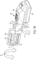
- Fig. 1B illustrates the axes of rotation.
- the intermediate section 130 is rotatable about an axis A, as shown by arrow A1.
- the lighting section 150 is rotatable about an axis B, as shown by arrow B 1.
- the axis B is a longitudinal axis of the lighting section 150 that runs through substantially the center of the lighting section 150.
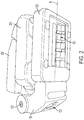
- Fig. 2 illustrates the intermediate section in a closed position with the light portion 151 pointing outwardly.
- This provides a compact configuration for the light 10 and allows the lighting section 151 to point out and illuminate objects. Accordingly, this configuration is both compact and open, because the lighting section 151, which includes a light projecting surface from which light projects, is not blocked.
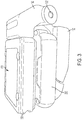
- Fig. 3 illustrates the light in the same configuration as shown in Fig. 2 , but with the LEDs 152 turned on so that the light portion 151 is illuminated.
- the light 10 effectively projects light to illuminate a surface. In the open position, significantly all of the light emitting surface of the light portion 151 is exposed allowing light to be emitted.
- Fig. 4 illustrates the light 10 with the intermediate section 130 in an open position so that the lighting section 150 is away from the base portion 100 and the battery 200.
- the intermediate section 132 may pivot about the hinge 132.
- Fig. 5 illustrates the light 10 in a closed position with the intermediate section 130 in a compact and closed position.
- the intermediate section 130 is in a closed position and the lighting section 150 is abutting the battery pack 200.
- the lighting section turned such that the light portion 151 abuts battery pack 200.
- illumination from the light 10 is blocked even when the light 10 is turned on. This may be useful to prevent unintended illumination.
- most of the light projecting surface of the lighting section 150 is blocked. In other embodiments more or less light may be blocked, including at least a majority of the light projecting surface being blocked.
- Fig. 6 illustrates the light 10 in another lighting position.
- the base portion 100 is again attached to a metal beam 500.
- the intermediate section 130 is rotated away from the battery pack 200 and the lighting section 150 is rotated with respect to the intermediate section 130.
- Fig. 7 is another view of the light 10 in a closed configuration.
- the mount 110 will be further described with reference to Figs. 8-19 .
- the mount 10 includes a pair of mount members 125.
- the mount members 125 each have a pair of metal plates 116 and a magnet 115.
- a portion of a housing of the mount members 125 is removed so that the magnet 115 can be seen.
- the magnet 115 is typically covered by a housing 117. However, in some embodiments, portions of the magnet 115 may be exposed.
- the mount members 125 are rotatable with respect to the base portion 100. This allows the mount members 125 to attach to various surfaces, such as curved surfaces, as will be described in further detail below.
- the mount members 125 are disposed directly next to each other. However, as discussed below, in other embodiments, mount members may be spaced apart from one another.
- Figs. 9-12 illustrate various views of the mount members.
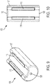
- Fig. 9 illustrates a perspective view of a mount member 125 and
- Fig. 10 illustrates a top view of the mount member 125.
- Fig. 11 is an end view of the mount member 125 and
- Fig. 12 is a cut-away view showing the magnet 115.
- each mount member 125 includes a mount member housing 117.
- a pair of metal plates 116 project through the housing 117 and can contact a surface.
- the mount members 125 also include a hinge hole 120 through which a rod runs allowing the mount members 125 to pivot.
- Fig. 12 illustrates a cut-away view of a mount member 125 so that the magnet 115 and metal plates 116 can be seen.
- the metal plates 116 are made of a ferrous material.
- the metal plates 116 together with the magnet 115 create a magnetic field that make the mount members 125 attract and attach to metal objects.
- the metal plate 116 and magnet 115 arrangement creates a strong magnetic field while protecting the magnet 115 itself from breaking, as magnets can often be brittle. Nevertheless, in other embodiments, the magnet 115 may be exposed.
- a magnet may also be used without metal plates.
- Figs. 13 and 14 illustrate the connection of the mount members 125 with the rest of the light 10.
- Fig. 13 is a top view of the light 10 with a portion of the base portion 100 removed so that the connection can be shown.
- Fig. 14 is a schematic top view. As shown in Figs. 13 and 14
- the base portion 100 of the light 10 includes a hole 118.
- the hole 118 is aligned with the hole 120 of the mount members 125.
- a rod 119 is then fitted through the holes 118 and 120.
- the mount members 125 are rotatably connected to the base portion 100.
- Other means and methods of rotatably attaching the mount members 125 to the base portion 100 or other portions of the light 10 may also be used.
- Figs. 15-19 illustrate a mount 210 of a slightly different embodiment.
- the mount 210 includes mount members 225 are substantially similar to the mount members 125, except as otherwise noted.
- the mount members 225 may be used in place of the mount members 125 in the exemplary embodiment of the light 10 shown in Figs. 1-8 .
- the mount members 125 may be used in place of mount members 225.
- the mount members 225 are spaced apart from one another.
- the mount members 225 are covered by a plastic housing 117.
- Fig. 15 illustrates a perspective view of the mount members 225
- Fig. 16 illustrates a cut-away perspective view of the mount members 225 which shows a cross section of the magnets 115 and steel plates 116.
- the magnets 115, steel plates 116 and housing 117 may be the same as those used for the mount members 125.
- the mount members 225 are held in a mount base 218 with a hinge rod 119.
- the mount members 225 include a hinge opening 120 that is concentric with the hinge rod 119 so that the rod 119 passes through the mount base 118. Accordingly, the mount members 225 are rotatably secured to the light 10 in a similar way as the mount members 125.
- the mount base 218 may allow the mount members 225 to be slightly or more extensively proud of the surface of the base portion of a light. For example, in Figs. 28 and 29 the mount bases 218 are slightly proud. In Figs. 30 and 31 , the mount bases 218 are attached to the base portion at a different location. The mount bases 218 may be moved to various locations of the base portion in other exemplary embodiments. In the embodiment of Figs. 1-8 , the mount members 125 are secured below a surface of the base portion 100. In any event, the mount members 125 and 225 may be secured more or less proud and in a variety of different manners and locations.
- the mount 210 can be attached to various surfaces.
- the illustration of Figs. 17-19 is similarly applicable to the mount 110 include mount members 125.
- the mount members are rotatable so that they can be secured to a surfaces of a variety of shapes.
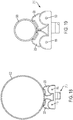
- the mount 210 is readily attachable to a flat metal surface 501.
- the mount members 225 are disposed parallel to one another. Owing to the rotatable nature of the mount members 225, the mount 210 also attaches to curved surfaces.
- the mount 210 can attach to a large diameter metal pipe 502, as is shown in Fig. 18 .
- the mount 210 can also attach to a small diameter metal pipe 503, as shown in Fig. 19 . This allows the light 10 to be attached to a variety of surface, whether flat, curved, or otherwise.
- the mount members 225 are shown as pivoting inwardly, towards one another, in Figs. 18 and 19 , they may also pivot outwardly, away from one another. This may be useful when connecting to, for example, a concave surface.
- Figs. 20-27 illustrate a light 310.
- the light 310 is identical to the light 10, except that it includes an additional hook feature.
- Fig. 20 illustrates a perspective view of the light 310 with the hook 320 in a stored position.
- Fig. 21 illustrates a perspective view of the light with the hook 320 in an extended position. In the extended position of Fig. 21 , the hook 320 may latch onto a pipe, railing or other surface so that the light 310 may hang from the surface.
- the base portion 300 includes a groove 330.
- the hook 320 is stored in the groove 330 when it is in the stored position, as shown in Fig. 20 .
- the base portion 300 is similar to the base portion 100 of the light 10 other than the alterations needed for the hook feature, such as the hook 320 and the groove 330.
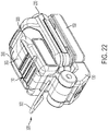
- Fig. 22 is another perspective view of the light 310 showing the hook 320 in an extended position.
- Fig. 23 illustrates the light 310 with the light portion 150 in an extended position and the hook 320 in a secured position.
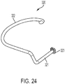
- Fig. 24 illustrates the hook 320.
- the hook 320 includes a curved end 322 that hooks onto pipes, railings or other objects. It also includes a securing end 321 that connects the hook 320 to the light 310.
- the hook 320 also includes a spring washer 323. The spring washer 323 helps to secure the hook 320 to the light 310 and also helps the hook 320 to stay in various discreet positions, as will be described in further detail below.
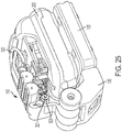
- Fig. 25 illustrates a cut-away view of the light 310. As shown in Fig. 25 , the washer 323 helps connect the hook 320 to the light 310.
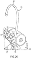
- Fig. 26 is a close up view of the connection of the hook 320 with the rest of the light 310.
- the securing end 321 of the hook 320 is inserted into the base portion 300 of the light 310.
- the hook 320 can be rotated such that it sits between a pair of detents 325 and will resist movement from that position. Accordingly, the hook 320 can be placed in a variety of discreet positions.
- the detents 325 are sufficiently large that the hook 320 will resist movement, but can be overcome by sufficient force from a user rotating the hook.
- the spring washer 323 is sufficiently flexible that the hook 320 can move outwardly from the hole in the base portion 300 and help the hook 320 to move between the positions delineated by the detents 325.
- Fig. 27 is a close-up view of the end section 321 of the hook 320 and the spring washer 323. A portion of the light 310 has been removed so that this section may be seen.
- Figs. 28 and 29 illustrate another exemplary embodiment of a light 410.
- the light 410 is similar to the lights 10 and 310. However, the light 410 omits the intermediate portion 130. Instead, the lighting section 150 is directly connected to the base portion 400. The lighting section 150 can rotate about two axes, in the same manner shown in Fig. 1B .
- An actuation switch (not shown) may be disposed on either the base portion 400 or the lighting section 150. Omitting the intermediate portion allows for a more compact light that may be cheaper to construct and more easily stored.
- the exemplary embodiment of the light 410 shown in Figs. 28 and 29 include the mount 210. However, it should be understood that the mount 110 may be used instead. Additionally, the hook 320 and related features of Figs. 20-27 may be added to the light 410.
- Fig. 28 illustrates the light 410 in an open position
- Fig. 29 shows light 410 in a closed position.
- Figs. 30 and 31 illustrate another exemplary embodiment of a light 510.
- the light 510 includes a base portion 500 which engaged with the battery 200 which powers the light.
- An activation switch 515 is disposed on the base portion 500, as shown in Fig. 30 .
- the mount 210 is disposed on a bottom portion of the light 510.
- the light 510 utilized a different lighting section 550.
- the lighting section 550 is a flashlight head. Light projects out of a lens 551. Light may be generated in the flashlight head 550 by one or more LEDs or by a bulb, for example. Additionally, the flashlight head 550 may include a reflector to direct the light.
- the flashlight head 550 is rotatable about an axis 552, as shown by the arrow C.
- the features of the various embodiments may be combined or substituted.
- the lighting section 550 may be substituted for the lighting section 150 and vice versa.
- the mounts 210 and 110 may be used in the various different embodiments, and the mounts 210, 110 may be placed at different locations on the lights.
- the intermediate section 130 may be added or removed from different embodiments. The location of the actuation switch may also be changed.
Landscapes
- Engineering & Computer Science (AREA)
- General Engineering & Computer Science (AREA)
- Non-Portable Lighting Devices Or Systems Thereof (AREA)
Claims (12)
- Licht (10, 310, 410, 510), umfassend:ein abnehmbares Batteriepack (200);einen Basisabschnitt (100, 300, 400), der dazu ausgebildet ist, das Batteriepack (200) aufzunehmen;einen Lichtbereich (150, 550), der betriebsfähig mit dem Basisabschnitt (100, 300, 400) verbunden ist, wobei der Lichtbereich (150, 550) einen Lichtgenerator beinhaltet, der Licht erzeugt; undeine Befestigung (110, 210), die an dem Basisabschnitt (100, 300, 400) angeordnet ist, wobei die Befestigung (110, 210) ein erstes Befestigungselement (125, 225) und ein zweites Befestigungselement (125, 225) umfasst;wobei sowohl das erste Befestigungselement (125, 225) als auch das zweite Befestigungselement (125, 225) unabhängig relativ zu dem Basisabschnitt (100, 300, 400) drehbar ist; undwobei sowohl das erste Befestigungselement (125, 225) als auch das zweite Befestigungselement (125, 225) einen Magneten (115) und ein Befestigungselementgehäuse (117) beinhaltet;dadurch gekennzeichnet, dass ein Paar eisenhaltiger Metallplatten (116) durch jedes Befestigungselementgehäuse (117) ragt, um eine Oberfläche zu kontaktieren, wobei die eisenhaltigen Metallplatten (116) und der Magnet (115) gemeinsam dazu ausgebildet sind, ein Magnetfeld zum Anbringen der Befestigungselemente (125, 225) an Metallobjekten zu erzeugen.
- Licht nach Anspruch 1, wobei das erste Befestigungselement (125, 225) und das zweite Befestigungselement (125, 225) aneinander angrenzen.
- Licht nach Anspruch 1 oder Anspruch 2, wobei das erste und zweite Befestigungselement (125, 225) im Wesentlichen parallel zueinander an dem Basisabschnitt (100, 300, 400) angeordnet sind.
- Licht nach einem vorstehenden Anspruch, wobei das erste und zweite Befestigungselement (125, 225) mittels jeweiliger Drehgelenke drehbar an dem Basisabschnitt (100, 300, 400) angeordnet sind.
- Licht nach Anspruch 4, wobei die Drehgelenke Scharnierstäbe (119) umfassen.
- Licht nach einem vorstehenden Anspruch, wobei die Befestigung (110, 210) eine Befestigungsbasis (218) an dem Basisabschnitt (100, 300, 400) angeordnet umfasst und das erste und zweite Befestigungselement (125, 225) drehbar an der Befestigungsbasis (218) angeordnet sind.
- Licht nach einem vorstehenden Anspruch, wobei sich das erste und zweite Befestigungselement (125, 225) entlang jeweiliger Drehachsen der Befestigungselemente erstrecken.
- Licht nach einem vorstehenden Anspruch, wobei jedes Befestigungselement (125, 225) mindestens eine Fläche beinhaltet, die mittels des Magneten (115) magnetisch ist.
- Licht nach Anspruch 8, wobei das erste Befestigungselement (125, 225) und das zweite Befestigungselement (125, 225) zu Positionen drehbar sind, sodass deren jeweilige magnetische Flächen parallel zueinander sind, jeweils voneinander wegzeigend und zueinander zeigend.
- Licht nach einem vorstehenden Anspruch, weiter umfassend einen Zwischenbereich (130), der zwischen dem Basisabschnitt (100, 300, 400) und dem Lichtbereich angeordnet ist.
- Licht nach Anspruch 10, wobei der Zwischenbereich (130) relativ zu dem Basisabschnitt (100, 300, 400) drehbar ist.
- Licht nach Anspruch 10 oder Anspruch 11, wobei der Lichtbereich (150, 550) relativ zu dem Zwischenbereich (130) drehbar ist.
Applications Claiming Priority (2)
| Application Number | Priority Date | Filing Date | Title |
|---|---|---|---|
| US201962820001P | 2019-03-18 | 2019-03-18 | |
| US16/807,333 US11255525B2 (en) | 2019-03-18 | 2020-03-03 | Battery powered light |
Publications (2)
| Publication Number | Publication Date |
|---|---|
| EP3712486A1 EP3712486A1 (de) | 2020-09-23 |
| EP3712486B1 true EP3712486B1 (de) | 2021-09-29 |
Family
ID=69845149
Family Applications (1)
| Application Number | Title | Priority Date | Filing Date |
|---|---|---|---|
| EP20163539.8A Active EP3712486B1 (de) | 2019-03-18 | 2020-03-17 | Batteriebetriebenes licht |
Country Status (2)
| Country | Link |
|---|---|
| US (5) | US11255525B2 (de) |
| EP (1) | EP3712486B1 (de) |
Cited By (1)
| Publication number | Priority date | Publication date | Assignee | Title |
|---|---|---|---|---|
| US12584615B2 (en) | 2019-03-18 | 2026-03-24 | Black & Decker Inc. | Battery powered light |
Families Citing this family (14)
| Publication number | Priority date | Publication date | Assignee | Title |
|---|---|---|---|---|
| CN111256054B (zh) | 2018-11-30 | 2023-11-07 | 米沃奇电动工具公司 | 便携式照明装置 |
| CN212617986U (zh) | 2019-11-22 | 2021-02-26 | 米沃奇电动工具公司 | 工作灯 |
| US11408593B2 (en) * | 2020-05-28 | 2022-08-09 | Klein Tools, Inc. | Lighting device for an aerial work platform |
| USD1032902S1 (en) | 2020-06-22 | 2024-06-25 | Milwaukee Electric Tool Corporation | Work light |
| US11732847B2 (en) * | 2021-01-12 | 2023-08-22 | Milwaukee Electric Tool Corporation | Portable light, such as a stick light |
| USD1092814S1 (en) | 2022-01-12 | 2025-09-09 | Milwaukee Electric Tool Corporation | Portable light |
| US12196380B2 (en) | 2022-05-24 | 2025-01-14 | Black & Decker Inc. | Portable illumination apparatus |
| US12385630B2 (en) | 2022-05-24 | 2025-08-12 | Black & Decker Inc. | Portable flashlight |
| JP7895816B2 (ja) * | 2022-09-13 | 2026-07-28 | 株式会社マキタ | 照明システム、ライト、及びホルダ |
| DE102023203037A1 (de) * | 2023-03-31 | 2024-10-02 | Robert Bosch Gesellschaft mit beschränkter Haftung | Arbeitslichtvorrichtung, Arbeitslicht und Verfahren zu einem Betrieb einer Arbeitslichtvorrichtung |
| US20250137619A1 (en) * | 2023-10-31 | 2025-05-01 | Milwaukee Electric Tool Corporation | Task light |
| US20250207743A1 (en) * | 2023-12-20 | 2025-06-26 | Milwaukee Electric Tool Corporation | Work light |
| USD1128964S1 (en) | 2024-03-20 | 2026-06-02 | Milwaukee Electric Tool Corporation | Task light |
| US20260126155A1 (en) * | 2024-11-06 | 2026-05-07 | Techtronic Cordless Gp | Work light |
Family Cites Families (88)
| Publication number | Priority date | Publication date | Assignee | Title |
|---|---|---|---|---|
| US2506400A (en) * | 1947-09-10 | 1950-05-02 | Louis K Wietz | Magnetic support |
| CH262015A (de) | 1947-10-30 | 1949-06-15 | Burren Glauser Alfred | Optischer Betrachtungs- und Beleuchtungsapparat für medizinische und technische Zwecke. |
| US4564894A (en) | 1984-12-12 | 1986-01-14 | Jorge Gonzalez | Trouble light for vehicles |
| US5012394A (en) * | 1988-11-15 | 1991-04-30 | Woodward John G | Hand portable light with extendable lamp housing |
| US4897768A (en) | 1989-02-27 | 1990-01-30 | Thul Andy J | Flashlight holder and mounted flashlight |
| US5871272A (en) | 1997-01-28 | 1999-02-16 | Streamlight, Incorporated | Flashlight with rotatable lamp head |
| AU7144798A (en) | 1997-05-16 | 1998-12-08 | Bausch & Lomb Incorporated | Adjustable magnifying apparatus and method for viewing video or computer screens |
| US6260985B1 (en) | 1999-07-23 | 2001-07-17 | Noel E. Zeller | Multipurpose portable electric lighting apparatus |
| FR2801112B3 (fr) | 1999-10-22 | 2001-12-07 | Lifatec Gmbh Faseroptik Optoel | Dispositif optique de grossissement eclairable |
| JP2001300867A (ja) * | 2000-04-21 | 2001-10-30 | Makita Corp | 電動工具用アダプタ |
| US6350040B1 (en) | 2000-05-05 | 2002-02-26 | Pelican Products, Inc. | Flashlight charger and rechargeable battery |
| AU2002245935B2 (en) * | 2001-04-09 | 2006-09-28 | Eveready Battery Company, Inc. | An improved lighting device |
| US6729413B2 (en) | 2001-08-24 | 2004-05-04 | Black & Decker Inc. | Power tool with battery pack ejector |
| US6736531B2 (en) * | 2002-01-16 | 2004-05-18 | Stewart Wallach | Reading light with shutoff timer |
| JP2003211374A (ja) | 2002-01-21 | 2003-07-29 | Hitachi Koki Co Ltd | 電動工具 |
| US6575590B1 (en) | 2002-03-01 | 2003-06-10 | Jake Wadsworth | Light system for battery powered drill |
| AU2003236424A1 (en) | 2002-08-23 | 2004-03-11 | Todd Kingsley Rangi | Electromagnetic work light |
| AU2003100946A4 (en) | 2002-11-15 | 2004-01-22 | Todd Kingsley Rangi | Magnetic worklight |
| US7578598B2 (en) | 2006-11-13 | 2009-08-25 | Black & Decker Inc. | Battery charging work light |
| US7048403B2 (en) | 2003-12-10 | 2006-05-23 | Pelican Products, Inc. | Light with a clip |
| US7296905B2 (en) | 2004-05-05 | 2007-11-20 | Black & Decker Inc. | Power tool work light |
| US20050265033A1 (en) | 2004-05-25 | 2005-12-01 | Yang A M | Light device for attaching to various tools |
| US7338189B2 (en) | 2004-08-10 | 2008-03-04 | Alert Safety Lite Products Co., Inc. | LED utility light with removable magnet |
| US7246927B2 (en) | 2004-12-07 | 2007-07-24 | Black & Decker Inc. | Fluorescent flashlight |
| US7222986B2 (en) | 2005-03-07 | 2007-05-29 | Daka Research Inc. | Multiple swivel flashlight |
| US7621652B2 (en) | 2005-03-31 | 2009-11-24 | Milwaukee Electric Tool Corporation | Electrical component, such as a lighting unit and battery charger assembly |
| US7309140B2 (en) * | 2005-12-07 | 2007-12-18 | Hiever Co., Ltd. | Light for jack |
| US7717586B2 (en) | 2007-01-18 | 2010-05-18 | E-Z Red Company | Foldable light |
| US7591572B1 (en) * | 2007-04-11 | 2009-09-22 | Levine Jonathan E | Compact lighting device |
| TWI383174B (zh) | 2007-07-04 | 2013-01-21 | Univ Far East | Separable magnifying glass lamp |
| DE112009001556T5 (de) | 2008-06-23 | 2011-04-28 | Milwaukee Electric Tool Corp., Brookfield | Elektrische Anordnung mit einer Akkuladefunktion |
| US7850330B2 (en) | 2008-08-20 | 2010-12-14 | Eveready Battery Co., Inc. | Lighting device configured to operate with different batteries |
| US20100084997A1 (en) | 2008-10-02 | 2010-04-08 | Joseph Anthony Oberzeir | Multi-mode utility lighting device |
| IT1392500B1 (it) | 2008-12-30 | 2012-03-09 | I B T S P A | Dispositivo di illuminazione a led a dissipazione di calore ottimizzata per esterni e grandi aree coperte |
| US8347705B2 (en) * | 2009-01-26 | 2013-01-08 | Charles Muhs | Magnetically mounted light for use in inspecting steel belted tires |
| US8142045B2 (en) * | 2009-05-04 | 2012-03-27 | Jason Peak | Utility light with articulating mounting legs adapted with suction cup fasteners |
| US7905623B2 (en) | 2009-07-08 | 2011-03-15 | Ming-Nan Chen | Magnetic illumination device for tool |
| US20110038064A1 (en) * | 2009-07-30 | 2011-02-17 | Ilo Kristo Xhunga | Flexible Arms of Low Footprint and High Weight-bearing |
| US8147087B2 (en) | 2009-12-28 | 2012-04-03 | Ming-Nan Chen | Magnetic illumination device for tool |
| US8186858B2 (en) | 2010-04-09 | 2012-05-29 | Ming-Nan Chen | Auxiliary illuminating structure for hand tool |
| DE102010031166A1 (de) | 2010-07-09 | 2012-01-12 | Robert Bosch Gmbh | Handleuchtgerät |
| DE102010031162A1 (de) | 2010-07-09 | 2012-01-12 | Robert Bosch Gmbh | Handleuchtgerät |
| USD680672S1 (en) | 2010-08-03 | 2013-04-23 | Streamlight, Inc. | Portable light |
| USD651731S1 (en) | 2011-04-27 | 2012-01-03 | Ad Ideas Of Wisconsin, Inc. | Work light |
| DE102011108709A1 (de) | 2011-07-28 | 2013-01-31 | Festool Group Gmbh & Co. Kg | Arbeitsleuchte |
| DE102011082209B8 (de) | 2011-09-06 | 2026-07-30 | Pictiva Displays International Limited | Leuchtmittel und verwendung |
| US9845940B2 (en) | 2012-06-11 | 2017-12-19 | Energizer Brands, Llc | Lighting device and light panel construction |
| JP5319004B1 (ja) | 2012-09-25 | 2013-10-16 | 株式会社エンジニア | スタンド付きルーペ |
| USD743072S1 (en) | 2012-12-28 | 2015-11-10 | Wilmar Corporation | Worklight |
| US20140272516A1 (en) | 2013-03-15 | 2014-09-18 | Black & Decker Inc. | Battery Pack With Heat Sink |
| DE102013205416A1 (de) | 2013-03-27 | 2014-10-16 | Robert Bosch Gmbh | Akkubetriebene Leuchteinheit |
| DE102014204971A1 (de) | 2013-05-14 | 2014-11-20 | Robert Bosch Gmbh | Arbeitslicht |
| US9372050B2 (en) | 2013-10-15 | 2016-06-21 | Colton Gill FRANKLIN | Magnetic gun barrel attachment |
| CN203880409U (zh) | 2014-01-21 | 2014-10-15 | 深圳高格新能源科技有限公司 | 一种家用能源照明系统 |
| CN104930360B (zh) | 2014-03-19 | 2019-07-12 | 余姚市金丰电器有限公司 | 一种发光装置及其方法 |
| JP6264136B2 (ja) * | 2014-03-25 | 2018-01-24 | 日立工機株式会社 | 照明器具 |
| DE102014206882B4 (de) | 2014-04-09 | 2020-01-16 | Carpetlight Gmbh | Flexibler Flächenbeleuchtungskörper und Beleuchtungssystem |
| US9638379B2 (en) * | 2015-03-11 | 2017-05-02 | Shanghai Easy—Use Tools Enterprise Co., Ltd. | Work lamp with magnetic tray and tools |
| CN204496105U (zh) | 2015-04-09 | 2015-07-22 | 温州富凯光学科技有限公司 | 折叠台灯放大镜 |
| US9651228B2 (en) | 2015-07-06 | 2017-05-16 | Shih Cheng Wang | Lighting device for hand tool |
| CN106678701A (zh) | 2015-11-09 | 2017-05-17 | 南京德朔实业有限公司 | 照明装置 |
| USD776321S1 (en) | 2016-01-22 | 2017-01-10 | West Coast Imports, Inc | Work light |
| CN105785564A (zh) | 2016-05-20 | 2016-07-20 | 上海勤煊信息科技有限公司 | 一种便携式台灯放大镜 |
| KR101755342B1 (ko) | 2016-05-31 | 2017-07-07 | 김태영 | 차량의 안전경고등 및 화재감지 기능을 갖는 캠핑 레저겸용 조명장치 |
| JP6876950B2 (ja) * | 2016-08-30 | 2021-05-26 | パナソニックIpマネジメント株式会社 | 照明器具 |
| US20180224077A1 (en) * | 2017-02-09 | 2018-08-09 | Aixia Bian | Methods and apparatus for a multi-functional folding straight light |
| CN108730939A (zh) | 2017-04-13 | 2018-11-02 | 光宝电子(广州)有限公司 | 发光装置 |
| US10317048B2 (en) | 2017-05-05 | 2019-06-11 | Coast Cutlery Co. | Pocket light |
| CN207555546U (zh) | 2017-11-07 | 2018-06-29 | 陈志明 | 一种放大镜灯 |
| CN208076825U (zh) | 2018-03-19 | 2018-11-09 | 浙江博宇光学有限公司 | 一种折叠式放大镜 |
| USD858837S1 (en) | 2018-05-08 | 2019-09-03 | Shawshank Ledz Inc. | LED light with clamp |
| USD882843S1 (en) | 2018-08-21 | 2020-04-28 | Erik A. Kaiser | Ring light |
| JP6890309B2 (ja) | 2019-02-01 | 2021-06-18 | パナソニックIpマネジメント株式会社 | 機能モジュール |
| JP6952265B2 (ja) | 2019-02-01 | 2021-10-20 | パナソニックIpマネジメント株式会社 | 機能モジュール |
| US11255525B2 (en) * | 2019-03-18 | 2022-02-22 | Black & Decker Inc. | Battery powered light |
| CN212617986U (zh) | 2019-11-22 | 2021-02-26 | 米沃奇电动工具公司 | 工作灯 |
| CN211372121U (zh) | 2019-11-27 | 2020-08-28 | 漳州立达信光电子科技有限公司 | 灯驱一体式模组及超薄灯具 |
| WO2022067072A1 (en) | 2020-09-24 | 2022-03-31 | Milwaukee Electric Tool Corporation | Portable lighting systems |
| USD965835S1 (en) | 2020-09-29 | 2022-10-04 | Chenhui Lu | LED ring light |
| USD932081S1 (en) | 2020-12-09 | 2021-09-28 | Bin Wang | Lamp |
| USD956307S1 (en) | 2021-02-03 | 2022-06-28 | Bin Wang | Lamp |
| US11913612B2 (en) | 2021-02-24 | 2024-02-27 | Nanjing Chervon Industry Co., Ltd. | Lighting device |
| US12467607B2 (en) | 2022-03-11 | 2025-11-11 | Techtronic Cordless Gp | Storage lights and mounting structures for the same |
| US12196380B2 (en) | 2022-05-24 | 2025-01-14 | Black & Decker Inc. | Portable illumination apparatus |
| US12129992B2 (en) | 2022-08-30 | 2024-10-29 | Walter R. Tucker Enterprises, Ltd | Clamping work light |
| DE102023203036A1 (de) | 2023-03-31 | 2024-10-02 | Robert Bosch Gesellschaft mit beschränkter Haftung | Arbeitslichtvorrichtung, Arbeitslicht und Verfahren zu einem Betrieb einer Arbeitslichtvorrichtung |
| DE102023203037A1 (de) | 2023-03-31 | 2024-10-02 | Robert Bosch Gesellschaft mit beschränkter Haftung | Arbeitslichtvorrichtung, Arbeitslicht und Verfahren zu einem Betrieb einer Arbeitslichtvorrichtung |
| DE102023203035A1 (de) | 2023-03-31 | 2024-10-02 | Robert Bosch Gesellschaft mit beschränkter Haftung | Arbeitslichtvorrichtung, Arbeitslicht und Verfahren zu einem Betrieb einer Arbeitslichtvorrichtung |
-
2020
- 2020-03-03 US US16/807,333 patent/US11255525B2/en active Active
- 2020-03-17 EP EP20163539.8A patent/EP3712486B1/de active Active
-
2022
- 2022-01-06 US US17/569,612 patent/US11530802B2/en active Active
- 2022-11-14 US US17/986,016 patent/US12169057B2/en active Active
-
2024
- 2024-11-13 US US18/946,368 patent/US12584615B2/en active Active
-
2026
- 2026-02-27 US US19/552,965 patent/US20260185685A1/en active Pending
Cited By (1)
| Publication number | Priority date | Publication date | Assignee | Title |
|---|---|---|---|---|
| US12584615B2 (en) | 2019-03-18 | 2026-03-24 | Black & Decker Inc. | Battery powered light |
Also Published As
| Publication number | Publication date |
|---|---|
| US20230075761A1 (en) | 2023-03-09 |
| US20200300446A1 (en) | 2020-09-24 |
| US12169057B2 (en) | 2024-12-17 |
| US12584615B2 (en) | 2026-03-24 |
| US20260185685A1 (en) | 2026-07-02 |
| US20220128226A1 (en) | 2022-04-28 |
| US11255525B2 (en) | 2022-02-22 |
| US11530802B2 (en) | 2022-12-20 |
| EP3712486A1 (de) | 2020-09-23 |
| US20250067422A1 (en) | 2025-02-27 |
Similar Documents
| Publication | Publication Date | Title |
|---|---|---|
| US12584615B2 (en) | Battery powered light | |
| EP3715701B1 (de) | Klemmbare arbeitsleuchte | |
| US8721120B2 (en) | Folding worklight with attachment mechanism | |
| US8303142B2 (en) | Folding rechargeable worklight | |
| EP3318366B1 (de) | Elektro-pool | |
| US9046231B2 (en) | Folding worklight with attachment mechanism | |
| USD483465S1 (en) | Combined ceiling fan and light fixture | |
| US7748127B1 (en) | Light fixture alignment tool | |
| US8764253B2 (en) | Hands-free multi-positional task light and method of use thereof | |
| US9638379B2 (en) | Work lamp with magnetic tray and tools | |
| EP2937623A1 (de) | Beleuchtungsvorrichtung | |
| US20240027058A1 (en) | Headlamp with detachable light assembly | |
| US20130258649A1 (en) | Portable light, such as a stick light | |
| US6530680B2 (en) | Utility flood light | |
| US20070086192A1 (en) | Adjustable working light with magnet | |
| US4965708A (en) | Light assembly having a magnetized base | |
| US5803586A (en) | Illuminated tool caddy | |
| US20070064415A1 (en) | Portable light having multi-mode reflector | |
| CA2745494C (en) | Folding worklight with attachment mechanism | |
| US7318701B2 (en) | Ceiling fan lighting system | |
| US20070041181A1 (en) | Lighting device for military use | |
| US20070014101A1 (en) | Auxiliary lamp for wrench | |
| JP5057738B2 (ja) | ドライバ用照明装置 | |
| US5769535A (en) | Portable lamp having multiple brightness projection | |
| EP3096069A1 (de) | Taschenlampe |
Legal Events
| Date | Code | Title | Description |
|---|---|---|---|
| PUAI | Public reference made under article 153(3) epc to a published international application that has entered the european phase |
Free format text: ORIGINAL CODE: 0009012 |
|
| STAA | Information on the status of an ep patent application or granted ep patent |
Free format text: STATUS: THE APPLICATION HAS BEEN PUBLISHED |
|
| AK | Designated contracting states |
Kind code of ref document: A1 Designated state(s): AL AT BE BG CH CY CZ DE DK EE ES FI FR GB GR HR HU IE IS IT LI LT LU LV MC MK MT NL NO PL PT RO RS SE SI SK SM TR |
|
| AX | Request for extension of the european patent |
Extension state: BA ME |
|
| STAA | Information on the status of an ep patent application or granted ep patent |
Free format text: STATUS: REQUEST FOR EXAMINATION WAS MADE |
|
| 17P | Request for examination filed |
Effective date: 20210317 |
|
| RBV | Designated contracting states (corrected) |
Designated state(s): AL AT BE BG CH CY CZ DE DK EE ES FI FR GB GR HR HU IE IS IT LI LT LU LV MC MK MT NL NO PL PT RO RS SE SI SK SM TR |
|
| GRAP | Despatch of communication of intention to grant a patent |
Free format text: ORIGINAL CODE: EPIDOSNIGR1 |
|
| STAA | Information on the status of an ep patent application or granted ep patent |
Free format text: STATUS: GRANT OF PATENT IS INTENDED |
|
| INTG | Intention to grant announced |
Effective date: 20210628 |
|
| GRAS | Grant fee paid |
Free format text: ORIGINAL CODE: EPIDOSNIGR3 |
|
| GRAA | (expected) grant |
Free format text: ORIGINAL CODE: 0009210 |
|
| STAA | Information on the status of an ep patent application or granted ep patent |
Free format text: STATUS: THE PATENT HAS BEEN GRANTED |
|
| AK | Designated contracting states |
Kind code of ref document: B1 Designated state(s): AL AT BE BG CH CY CZ DE DK EE ES FI FR GB GR HR HU IE IS IT LI LT LU LV MC MK MT NL NO PL PT RO RS SE SI SK SM TR |
|
| REG | Reference to a national code |
Ref country code: GB Ref legal event code: FG4D |
|
| REG | Reference to a national code |
Ref country code: CH Ref legal event code: EP Ref country code: AT Ref legal event code: REF Ref document number: 1434509 Country of ref document: AT Kind code of ref document: T Effective date: 20211015 |
|
| REG | Reference to a national code |
Ref country code: DE Ref legal event code: R096 Ref document number: 602020000619 Country of ref document: DE |
|
| REG | Reference to a national code |
Ref country code: IE Ref legal event code: FG4D |
|
| REG | Reference to a national code |
Ref country code: LT Ref legal event code: MG9D |
|
| PG25 | Lapsed in a contracting state [announced via postgrant information from national office to epo] |
Ref country code: RS Free format text: LAPSE BECAUSE OF FAILURE TO SUBMIT A TRANSLATION OF THE DESCRIPTION OR TO PAY THE FEE WITHIN THE PRESCRIBED TIME-LIMIT Effective date: 20210929 Ref country code: SE Free format text: LAPSE BECAUSE OF FAILURE TO SUBMIT A TRANSLATION OF THE DESCRIPTION OR TO PAY THE FEE WITHIN THE PRESCRIBED TIME-LIMIT Effective date: 20210929 Ref country code: FI Free format text: LAPSE BECAUSE OF FAILURE TO SUBMIT A TRANSLATION OF THE DESCRIPTION OR TO PAY THE FEE WITHIN THE PRESCRIBED TIME-LIMIT Effective date: 20210929 Ref country code: HR Free format text: LAPSE BECAUSE OF FAILURE TO SUBMIT A TRANSLATION OF THE DESCRIPTION OR TO PAY THE FEE WITHIN THE PRESCRIBED TIME-LIMIT Effective date: 20210929 Ref country code: NO Free format text: LAPSE BECAUSE OF FAILURE TO SUBMIT A TRANSLATION OF THE DESCRIPTION OR TO PAY THE FEE WITHIN THE PRESCRIBED TIME-LIMIT Effective date: 20211229 Ref country code: BG Free format text: LAPSE BECAUSE OF FAILURE TO SUBMIT A TRANSLATION OF THE DESCRIPTION OR TO PAY THE FEE WITHIN THE PRESCRIBED TIME-LIMIT Effective date: 20211229 Ref country code: LT Free format text: LAPSE BECAUSE OF FAILURE TO SUBMIT A TRANSLATION OF THE DESCRIPTION OR TO PAY THE FEE WITHIN THE PRESCRIBED TIME-LIMIT Effective date: 20210929 |
|
| REG | Reference to a national code |
Ref country code: NL Ref legal event code: MP Effective date: 20210929 |
|
| REG | Reference to a national code |
Ref country code: AT Ref legal event code: MK05 Ref document number: 1434509 Country of ref document: AT Kind code of ref document: T Effective date: 20210929 |
|
| PG25 | Lapsed in a contracting state [announced via postgrant information from national office to epo] |
Ref country code: LV Free format text: LAPSE BECAUSE OF FAILURE TO SUBMIT A TRANSLATION OF THE DESCRIPTION OR TO PAY THE FEE WITHIN THE PRESCRIBED TIME-LIMIT Effective date: 20210929 Ref country code: GR Free format text: LAPSE BECAUSE OF FAILURE TO SUBMIT A TRANSLATION OF THE DESCRIPTION OR TO PAY THE FEE WITHIN THE PRESCRIBED TIME-LIMIT Effective date: 20211230 |
|
| PG25 | Lapsed in a contracting state [announced via postgrant information from national office to epo] |
Ref country code: AT Free format text: LAPSE BECAUSE OF FAILURE TO SUBMIT A TRANSLATION OF THE DESCRIPTION OR TO PAY THE FEE WITHIN THE PRESCRIBED TIME-LIMIT Effective date: 20210929 |
|
| PG25 | Lapsed in a contracting state [announced via postgrant information from national office to epo] |
Ref country code: IS Free format text: LAPSE BECAUSE OF FAILURE TO SUBMIT A TRANSLATION OF THE DESCRIPTION OR TO PAY THE FEE WITHIN THE PRESCRIBED TIME-LIMIT Effective date: 20220129 Ref country code: SK Free format text: LAPSE BECAUSE OF FAILURE TO SUBMIT A TRANSLATION OF THE DESCRIPTION OR TO PAY THE FEE WITHIN THE PRESCRIBED TIME-LIMIT Effective date: 20210929 Ref country code: RO Free format text: LAPSE BECAUSE OF FAILURE TO SUBMIT A TRANSLATION OF THE DESCRIPTION OR TO PAY THE FEE WITHIN THE PRESCRIBED TIME-LIMIT Effective date: 20210929 Ref country code: PT Free format text: LAPSE BECAUSE OF FAILURE TO SUBMIT A TRANSLATION OF THE DESCRIPTION OR TO PAY THE FEE WITHIN THE PRESCRIBED TIME-LIMIT Effective date: 20220131 Ref country code: PL Free format text: LAPSE BECAUSE OF FAILURE TO SUBMIT A TRANSLATION OF THE DESCRIPTION OR TO PAY THE FEE WITHIN THE PRESCRIBED TIME-LIMIT Effective date: 20210929 Ref country code: NL Free format text: LAPSE BECAUSE OF FAILURE TO SUBMIT A TRANSLATION OF THE DESCRIPTION OR TO PAY THE FEE WITHIN THE PRESCRIBED TIME-LIMIT Effective date: 20210929 Ref country code: ES Free format text: LAPSE BECAUSE OF FAILURE TO SUBMIT A TRANSLATION OF THE DESCRIPTION OR TO PAY THE FEE WITHIN THE PRESCRIBED TIME-LIMIT Effective date: 20210929 Ref country code: EE Free format text: LAPSE BECAUSE OF FAILURE TO SUBMIT A TRANSLATION OF THE DESCRIPTION OR TO PAY THE FEE WITHIN THE PRESCRIBED TIME-LIMIT Effective date: 20210929 Ref country code: CZ Free format text: LAPSE BECAUSE OF FAILURE TO SUBMIT A TRANSLATION OF THE DESCRIPTION OR TO PAY THE FEE WITHIN THE PRESCRIBED TIME-LIMIT Effective date: 20210929 Ref country code: AL Free format text: LAPSE BECAUSE OF FAILURE TO SUBMIT A TRANSLATION OF THE DESCRIPTION OR TO PAY THE FEE WITHIN THE PRESCRIBED TIME-LIMIT Effective date: 20210929 |
|
| REG | Reference to a national code |
Ref country code: DE Ref legal event code: R097 Ref document number: 602020000619 Country of ref document: DE |
|
| PG25 | Lapsed in a contracting state [announced via postgrant information from national office to epo] |
Ref country code: DK Free format text: LAPSE BECAUSE OF FAILURE TO SUBMIT A TRANSLATION OF THE DESCRIPTION OR TO PAY THE FEE WITHIN THE PRESCRIBED TIME-LIMIT Effective date: 20210929 |
|
| PLBE | No opposition filed within time limit |
Free format text: ORIGINAL CODE: 0009261 |
|
| STAA | Information on the status of an ep patent application or granted ep patent |
Free format text: STATUS: NO OPPOSITION FILED WITHIN TIME LIMIT |
|
| 26N | No opposition filed |
Effective date: 20220630 |
|
| PG25 | Lapsed in a contracting state [announced via postgrant information from national office to epo] |
Ref country code: MC Free format text: LAPSE BECAUSE OF FAILURE TO SUBMIT A TRANSLATION OF THE DESCRIPTION OR TO PAY THE FEE WITHIN THE PRESCRIBED TIME-LIMIT Effective date: 20210929 |
|
| PG25 | Lapsed in a contracting state [announced via postgrant information from national office to epo] |
Ref country code: SI Free format text: LAPSE BECAUSE OF FAILURE TO SUBMIT A TRANSLATION OF THE DESCRIPTION OR TO PAY THE FEE WITHIN THE PRESCRIBED TIME-LIMIT Effective date: 20210929 |
|
| REG | Reference to a national code |
Ref country code: BE Ref legal event code: MM Effective date: 20220331 |
|
| PG25 | Lapsed in a contracting state [announced via postgrant information from national office to epo] |
Ref country code: LU Free format text: LAPSE BECAUSE OF NON-PAYMENT OF DUE FEES Effective date: 20220317 Ref country code: IT Free format text: LAPSE BECAUSE OF FAILURE TO SUBMIT A TRANSLATION OF THE DESCRIPTION OR TO PAY THE FEE WITHIN THE PRESCRIBED TIME-LIMIT Effective date: 20210929 Ref country code: IE Free format text: LAPSE BECAUSE OF NON-PAYMENT OF DUE FEES Effective date: 20220317 Ref country code: FR Free format text: LAPSE BECAUSE OF NON-PAYMENT OF DUE FEES Effective date: 20220331 |
|
| PG25 | Lapsed in a contracting state [announced via postgrant information from national office to epo] |
Ref country code: BE Free format text: LAPSE BECAUSE OF NON-PAYMENT OF DUE FEES Effective date: 20220331 |
|
| REG | Reference to a national code |
Ref country code: CH Ref legal event code: PL |
|
| PG25 | Lapsed in a contracting state [announced via postgrant information from national office to epo] |
Ref country code: LI Free format text: LAPSE BECAUSE OF NON-PAYMENT OF DUE FEES Effective date: 20230331 Ref country code: CH Free format text: LAPSE BECAUSE OF NON-PAYMENT OF DUE FEES Effective date: 20230331 |
|
| PG25 | Lapsed in a contracting state [announced via postgrant information from national office to epo] |
Ref country code: SM Free format text: LAPSE BECAUSE OF FAILURE TO SUBMIT A TRANSLATION OF THE DESCRIPTION OR TO PAY THE FEE WITHIN THE PRESCRIBED TIME-LIMIT Effective date: 20210929 Ref country code: MK Free format text: LAPSE BECAUSE OF FAILURE TO SUBMIT A TRANSLATION OF THE DESCRIPTION OR TO PAY THE FEE WITHIN THE PRESCRIBED TIME-LIMIT Effective date: 20210929 Ref country code: CY Free format text: LAPSE BECAUSE OF FAILURE TO SUBMIT A TRANSLATION OF THE DESCRIPTION OR TO PAY THE FEE WITHIN THE PRESCRIBED TIME-LIMIT Effective date: 20210929 |
|
| PG25 | Lapsed in a contracting state [announced via postgrant information from national office to epo] |
Ref country code: HU Free format text: LAPSE BECAUSE OF FAILURE TO SUBMIT A TRANSLATION OF THE DESCRIPTION OR TO PAY THE FEE WITHIN THE PRESCRIBED TIME-LIMIT; INVALID AB INITIO Effective date: 20200317 |
|
| PG25 | Lapsed in a contracting state [announced via postgrant information from national office to epo] |
Ref country code: TR Free format text: LAPSE BECAUSE OF FAILURE TO SUBMIT A TRANSLATION OF THE DESCRIPTION OR TO PAY THE FEE WITHIN THE PRESCRIBED TIME-LIMIT Effective date: 20210929 |
|
| PG25 | Lapsed in a contracting state [announced via postgrant information from national office to epo] |
Ref country code: MT Free format text: LAPSE BECAUSE OF FAILURE TO SUBMIT A TRANSLATION OF THE DESCRIPTION OR TO PAY THE FEE WITHIN THE PRESCRIBED TIME-LIMIT Effective date: 20210929 |
|
| PGFP | Annual fee paid to national office [announced via postgrant information from national office to epo] |
Ref country code: GB Payment date: 20260324 Year of fee payment: 7 |
|
| PGFP | Annual fee paid to national office [announced via postgrant information from national office to epo] |
Ref country code: DE Payment date: 20260320 Year of fee payment: 7 |