EP3712453A1 - Coupling with improved sleeve-ring connection - Google Patents
Coupling with improved sleeve-ring connection Download PDFInfo
- Publication number
- EP3712453A1 EP3712453A1 EP19163960.8A EP19163960A EP3712453A1 EP 3712453 A1 EP3712453 A1 EP 3712453A1 EP 19163960 A EP19163960 A EP 19163960A EP 3712453 A1 EP3712453 A1 EP 3712453A1
- Authority
- EP
- European Patent Office
- Prior art keywords
- ring
- coupling
- bushing
- shaft
- assembly
- Prior art date
- Legal status (The legal status is an assumption and is not a legal conclusion. Google has not performed a legal analysis and makes no representation as to the accuracy of the status listed.)
- Granted
Links
- 230000008878 coupling Effects 0.000 title claims abstract description 70
- 238000010168 coupling process Methods 0.000 title claims abstract description 70
- 238000005859 coupling reaction Methods 0.000 title claims abstract description 70
- 238000000034 method Methods 0.000 claims abstract description 29
- 241000446313 Lamella Species 0.000 claims abstract description 16
- 239000007769 metal material Substances 0.000 claims description 8
- 229920003023 plastic Polymers 0.000 claims description 7
- 239000004033 plastic Substances 0.000 claims description 7
- 238000003825 pressing Methods 0.000 claims description 5
- 240000000731 Fagus sylvatica Species 0.000 claims 1
- 235000010099 Fagus sylvatica Nutrition 0.000 claims 1
- 238000004519 manufacturing process Methods 0.000 description 14
- 230000005540 biological transmission Effects 0.000 description 3
- 229920001971 elastomer Polymers 0.000 description 3
- 239000000806 elastomer Substances 0.000 description 3
- 239000004568 cement Substances 0.000 description 2
- 230000005489 elastic deformation Effects 0.000 description 2
- 230000007246 mechanism Effects 0.000 description 2
- 230000008569 process Effects 0.000 description 2
- 239000011435 rock Substances 0.000 description 2
- 229910000838 Al alloy Inorganic materials 0.000 description 1
- 229910000851 Alloy steel Inorganic materials 0.000 description 1
- RYGMFSIKBFXOCR-UHFFFAOYSA-N Copper Chemical compound [Cu] RYGMFSIKBFXOCR-UHFFFAOYSA-N 0.000 description 1
- 229910000881 Cu alloy Inorganic materials 0.000 description 1
- 229910000831 Steel Inorganic materials 0.000 description 1
- XAGFODPZIPBFFR-UHFFFAOYSA-N aluminium Chemical compound [Al] XAGFODPZIPBFFR-UHFFFAOYSA-N 0.000 description 1
- 229910052782 aluminium Inorganic materials 0.000 description 1
- 230000015556 catabolic process Effects 0.000 description 1
- 238000006243 chemical reaction Methods 0.000 description 1
- 238000002485 combustion reaction Methods 0.000 description 1
- 230000000295 complement effect Effects 0.000 description 1
- 229910052802 copper Inorganic materials 0.000 description 1
- 239000010949 copper Substances 0.000 description 1
- 238000006731 degradation reaction Methods 0.000 description 1
- 230000006872 improvement Effects 0.000 description 1
- 230000010354 integration Effects 0.000 description 1
- 230000003993 interaction Effects 0.000 description 1
- 230000007774 longterm Effects 0.000 description 1
- 238000012423 maintenance Methods 0.000 description 1
- 230000008439 repair process Effects 0.000 description 1
- 239000010959 steel Substances 0.000 description 1
Images


Classifications
-
- F—MECHANICAL ENGINEERING; LIGHTING; HEATING; WEAPONS; BLASTING
- F16—ENGINEERING ELEMENTS AND UNITS; GENERAL MEASURES FOR PRODUCING AND MAINTAINING EFFECTIVE FUNCTIONING OF MACHINES OR INSTALLATIONS; THERMAL INSULATION IN GENERAL
- F16D—COUPLINGS FOR TRANSMITTING ROTATION; CLUTCHES; BRAKES
- F16D3/00—Yielding couplings, i.e. with means permitting movement between the connected parts during the drive
- F16D3/50—Yielding couplings, i.e. with means permitting movement between the connected parts during the drive with the coupling parts connected by one or more intermediate members
- F16D3/56—Yielding couplings, i.e. with means permitting movement between the connected parts during the drive with the coupling parts connected by one or more intermediate members comprising elastic metal lamellae, elastic rods, or the like, e.g. arranged radially or parallel to the axis, the members being shear-loaded collectively by the total load
-
- F—MECHANICAL ENGINEERING; LIGHTING; HEATING; WEAPONS; BLASTING
- F16—ENGINEERING ELEMENTS AND UNITS; GENERAL MEASURES FOR PRODUCING AND MAINTAINING EFFECTIVE FUNCTIONING OF MACHINES OR INSTALLATIONS; THERMAL INSULATION IN GENERAL
- F16D—COUPLINGS FOR TRANSMITTING ROTATION; CLUTCHES; BRAKES
- F16D3/00—Yielding couplings, i.e. with means permitting movement between the connected parts during the drive
- F16D3/50—Yielding couplings, i.e. with means permitting movement between the connected parts during the drive with the coupling parts connected by one or more intermediate members
- F16D3/78—Yielding couplings, i.e. with means permitting movement between the connected parts during the drive with the coupling parts connected by one or more intermediate members shaped as an elastic disc or flat ring, arranged perpendicular to the axis of the coupling parts, different sets of spots of the disc or ring being attached to each coupling part, e.g. Hardy couplings
-
- F—MECHANICAL ENGINEERING; LIGHTING; HEATING; WEAPONS; BLASTING
- F16—ENGINEERING ELEMENTS AND UNITS; GENERAL MEASURES FOR PRODUCING AND MAINTAINING EFFECTIVE FUNCTIONING OF MACHINES OR INSTALLATIONS; THERMAL INSULATION IN GENERAL
- F16D—COUPLINGS FOR TRANSMITTING ROTATION; CLUTCHES; BRAKES
- F16D2300/00—Special features for couplings or clutches
- F16D2300/12—Mounting or assembling
-
- F—MECHANICAL ENGINEERING; LIGHTING; HEATING; WEAPONS; BLASTING
- F16—ENGINEERING ELEMENTS AND UNITS; GENERAL MEASURES FOR PRODUCING AND MAINTAINING EFFECTIVE FUNCTIONING OF MACHINES OR INSTALLATIONS; THERMAL INSULATION IN GENERAL
- F16D—COUPLINGS FOR TRANSMITTING ROTATION; CLUTCHES; BRAKES
- F16D3/00—Yielding couplings, i.e. with means permitting movement between the connected parts during the drive
- F16D3/50—Yielding couplings, i.e. with means permitting movement between the connected parts during the drive with the coupling parts connected by one or more intermediate members
- F16D3/78—Yielding couplings, i.e. with means permitting movement between the connected parts during the drive with the coupling parts connected by one or more intermediate members shaped as an elastic disc or flat ring, arranged perpendicular to the axis of the coupling parts, different sets of spots of the disc or ring being attached to each coupling part, e.g. Hardy couplings
- F16D3/79—Yielding couplings, i.e. with means permitting movement between the connected parts during the drive with the coupling parts connected by one or more intermediate members shaped as an elastic disc or flat ring, arranged perpendicular to the axis of the coupling parts, different sets of spots of the disc or ring being attached to each coupling part, e.g. Hardy couplings the disc or ring being metallic
-
- Y—GENERAL TAGGING OF NEW TECHNOLOGICAL DEVELOPMENTS; GENERAL TAGGING OF CROSS-SECTIONAL TECHNOLOGIES SPANNING OVER SEVERAL SECTIONS OF THE IPC; TECHNICAL SUBJECTS COVERED BY FORMER USPC CROSS-REFERENCE ART COLLECTIONS [XRACs] AND DIGESTS
- Y02—TECHNOLOGIES OR APPLICATIONS FOR MITIGATION OR ADAPTATION AGAINST CLIMATE CHANGE
- Y02E—REDUCTION OF GREENHOUSE GAS [GHG] EMISSIONS, RELATED TO ENERGY GENERATION, TRANSMISSION OR DISTRIBUTION
- Y02E10/00—Energy generation through renewable energy sources
- Y02E10/70—Wind energy
- Y02E10/72—Wind turbines with rotation axis in wind direction
-
- Y—GENERAL TAGGING OF NEW TECHNOLOGICAL DEVELOPMENTS; GENERAL TAGGING OF CROSS-SECTIONAL TECHNOLOGIES SPANNING OVER SEVERAL SECTIONS OF THE IPC; TECHNICAL SUBJECTS COVERED BY FORMER USPC CROSS-REFERENCE ART COLLECTIONS [XRACs] AND DIGESTS
- Y10—TECHNICAL SUBJECTS COVERED BY FORMER USPC
- Y10T—TECHNICAL SUBJECTS COVERED BY FORMER US CLASSIFICATION
- Y10T29/00—Metal working
- Y10T29/49—Method of mechanical manufacture
- Y10T29/49826—Assembling or joining
- Y10T29/49895—Associating parts by use of aligning means [e.g., use of a drift pin or a "fixture"]
-
- Y—GENERAL TAGGING OF NEW TECHNOLOGICAL DEVELOPMENTS; GENERAL TAGGING OF CROSS-SECTIONAL TECHNOLOGIES SPANNING OVER SEVERAL SECTIONS OF THE IPC; TECHNICAL SUBJECTS COVERED BY FORMER USPC CROSS-REFERENCE ART COLLECTIONS [XRACs] AND DIGESTS
- Y10—TECHNICAL SUBJECTS COVERED BY FORMER USPC
- Y10T—TECHNICAL SUBJECTS COVERED BY FORMER US CLASSIFICATION
- Y10T403/00—Joints and connections
- Y10T403/71—Rod side to plate or side
- Y10T403/7176—Resilient clip
Definitions
- the invention relates to a coupling with a disk pack, in which an improved connection is formed between a bushing and a ring in an assembly opening.
- the invention also relates to a manufacturing method for a corresponding coupling.
- the invention also relates to a shaft arrangement which has a corresponding coupling.
- the invention also relates to an industrial application which is equipped with such a shaft arrangement.
- the pamphlet US 2010/099505 A1 discloses a multi-disk clutch comprising a disk pack which is attached between two clutch halves.
- the plate pack is connected by bolts to the flanges of the coupling halves, which are held in sleeves.
- the sleeves are essentially designed as collar sleeves, which are connected to the disk pack by pressing.
- an elastic coupling which has a plurality of disk bodies which are connected to a hub.
- the disk bodies have aligned openings in a radially inner region, in each of which a rivet is attached.
- the rivet is connected to the hub and thus binds the disc body to the hub.
- the disk bodies are held together by a flange in a radially outer area.
- the invention is based on the object of providing a clutch which offers an improvement in at least one of the points described.
- the clutch comprises a plurality of disks which are designed to transmit tensile forces during operation of the clutch and thus to transmit torque from a first clutch side to a second clutch side.
- the lamellas are bundled, i.e. combined to form lamella sets.
- Lamella bores are formed in the lamellae and the lamellae are arranged in the lamella pack so that the lamellae bores are aligned.
- at least one assembly opening is formed in the disk pack, via which the disk pack can be connected to the first or second clutch side.
- the connection between the disk pack and a clutch side is ensured, for example, by a bolt.
- the socket accordingly has at least one hollow cylindrical section.
- the socket can be connected to a ring in a form-fitting manner.
- the socket has a shape which can be resiliently, ie essentially elastically, deformed by an assembly force, and thus a form fit with the ring is produced.
- the positive fit produced in this way prevents the ring from separating from the bushing in an axial direction.
- the ring is designed in such a way that, in the assembled state, it complements the shape of the bushing in the respective first end region essentially to form a collar bushing.
- a form-fitting connection between the bushing and the ring allows their assembly and, if necessary, also disassembly to be carried out in a simple manner with low assembly forces. Accordingly, simpler tools can be used, or several rings can be connected with bushings at the same time with relatively little effort. As a result, a coupling according to the invention can be produced quickly and cost-effectively. Due to the reduced assembly forces, dismantling can be carried out just as easily, what the ease of maintenance in a variety of industrial applications increases.
- the socket and / or the ring can be designed to be deformable for a releasable connection.
- the bush can be deformed in such a way that the ring can be pushed over the bush. Accordingly, the ring can also be deformed when it is pushed onto the socket.
- Deformation is to be understood as meaning essentially elastic deformation, in which plastic deformation components are negligible in the case of a single assembly. This can cause a restoring force in the ring and / or the socket.
- a force fit and / or a form fit can be present between the bushing and the ring.
- a frictional connection can be present, for example, between an inner surface of the ring and an outer surface in the end region of the socket.
- a form fit in turn, can be produced, for example, by a clip connection between the ring and the socket.
- a form fit has a reduced tendency to relax and thus offers a high level of holding power over the long term.
- a clip connection can be established, for example, by a latching lug on the outer surface of the socket in the corresponding end area or on the inner surface of the ring.
- a locking groove can be formed to correspond to the locking lug on the socket or the ring.
- Such clip connections can be designed in a simple manner in such a way that a desired assembly force can be set.
- the other mechanical requirements on the socket or ring can remain unaffected. Accordingly, the claimed solution can be easily adapted for a large number of applications.
- a clip connection engages automatically during assembly, which further simplifies the assembly process.
- the claimed Coupling size-specific tools such as pressure cones for cold forming, are unnecessary.
- the bushing and / or the ring can be made of a metallic material, for example a steel, a steel alloy, copper, a copper alloy, aluminum, or an aluminum alloy.
- Metallic materials offer a high degree of strength and can be processed in a tried and tested manner.
- a metallic material can in particular be machined in such a way that the socket and / or the ring are so soft in the area of the positive connection, for example on the inner surface of the ring or an end area of the socket, that a reduced assembly force can be achieved.
- the socket and / or the ring can be designed in such a way that they otherwise offer a high degree of stability.
- the ring and / or the socket can be made of plastic.
- Plastics offer low density and are cost effective. Plastics are also electrically insulating and thus make it possible to protect components connected to one another via the coupling and thus to implement the principle of functional integration.
- the socket has a collar on one side which is integrally formed.
- the socket can thus be designed as a collar socket.
- Such a collar makes it possible to support the bushing on one side against the lamella pack and to complete the assembly by attaching the ring to the end area facing away from the collar.
- the number of components required is minimized by using a collar and ring. As a result, the number of assembly steps is also reduced.
- the socket can also be designed to be positively connectable in a first and a second end area, that is to say on both sides, with one ring each. Accordingly, a socket is positively connected with two rings for assembly.
- the form-fitting connections between the socket and the rings can be produced in the same way in the first and second end regions.
- rings that are attached to the first and second end regions of the bushing can be constructed identically, that is to say interchangeable with one another. This also reduces the number of different components.
- a socket without a collar represents a relatively simple component that can be produced quickly and cost-effectively. As a result, the claimed solution can be implemented in a particularly economical manner.
- an intermediate ring can be arranged between the bushing and the ring in the assembled state.
- the intermediate ring is used to produce the force fit and / or the form fit between the socket and the ring.
- the intermediate ring can, for example, be made of an elastomer and, during assembly, can be arranged on the corresponding end region of the bushing or on the inner surface of the ring.
- the intermediate ring can be positioned in a latching groove which is formed in the end region of the bush or on the inner surface of the ring.
- the intermediate ring can serve as a seal.
- the intermediate ring can be used specifically as a wear part, so that when the coupling is reassembled, damage or degradation of the bushing and / or the ring can be ruled out.
- the intermediate ring can be made from a metallic material or from a plastic, for example an elastomer. Intermediate rings made of a metallic material can be manufactured with high precision and have a long service life. Plastics, on the other hand, are cost-efficient and therefore particularly suitable as wear parts.
- the ring with the bushing can be preferred by means of an assembly force, that is to say a pressing force, of up to 15 kN of up to 10 kN, more preferably of up to 8 kN, particularly preferably of up to 6.5 kN.
- assembly forces can already be exerted, for example, by simple hydraulic tools or electrically operated machines.
- the claimed solution can be designed in a simple manner in terms of assembly force. Accordingly, only low requirements are placed on the production of the claimed coupling.
- the socket can be provided with an alignment groove and / or an alignment spring.
- the locking lug or locking groove in the end region of the socket is interrupted by the alignment groove or alignment spring.
- the ring can be provided with an alignment groove and / or alignment spring.
- at least one alignment groove and at least one alignment spring of the ring or the socket can be designed to correspond to one another. This ensures an exact angular position of the ring with respect to the socket in the assembled state.
- the alignment groove and / or alignment spring can be arranged between a locking groove and a locking lug in the end region of the socket.
- the alignment groove or alignment spring interrupts an alternating sequence of at least one latching groove and one latching spring along the circumferential direction.
- the ring can also be equipped on its inner surface with at least one locking groove and one locking spring, between which an alignment groove or alignment spring is positioned.
- the underlying object is also achieved by the production method according to the invention.
- the method according to the invention comprises a first step in which a disk pack is provided which has a plurality of assembly openings, at least several of which are to be provided with a bushing.
- the sockets are inserted into the corresponding assembly openings.
- a third process step is also carried out in which each of the sockets is connected to a ring. To be the rings pressed against the sockets. According to the invention, a positive connection is established between the sockets and the respective rings.
- the rings are connected in a form-fitting manner essentially simultaneously with the respective bushings.
- several rings can be pressed onto the sockets with a stamp.
- the sockets can also be pressed onto the rings by a stamp.
- the production of the coupling is accelerated and simplified by the essentially simultaneous connection of bushings and rings. In particular, this increases the economic efficiency in the production of couplings with a large number of assembly openings.
- size-specific tools such as pressure cones for cold forming, are unnecessary in the claimed method.
- the claimed method can be carried out quickly with a reduced outlay on tools.
- disk packs of different sizes can be produced quickly one after the other without the need for conversion.
- the claimed method is therefore flexible, which offers increased productivity in the manufacture of couplings.
- At least one of the form-fitting connections that is formed between the sockets and the corresponding rings is designed as a releasable connection.
- a releasable connection between the bushing and the ring is to be understood as a connection, after the release of which the bushing and / or the ring can be reused. This can be a clip connection, for example. With a releasable connection, the couplings produced according to the claimed method can be inspected and repaired particularly easily.
- the underlying object is also achieved by the shaft arrangement according to the invention.
- the shaft arrangement comprises a first shaft which is connected to a second shaft via a coupling.
- the coupling ensures a transmission of torque from the first to the second shaft or vice versa.
- the coupling that connects the first and second shaft is designed according to one of the embodiments outlined above.
- the task presented at the beginning is likewise achieved by the industrial application according to the invention.
- the industrial application includes a drive unit that can be designed as an electric motor, internal combustion engine or hydraulic motor, for example.
- the drive unit has a first shaft via which a drive power generated by the drive unit is provided.
- the industrial application also has a mechanical application that can be designed, for example, as a mill, vertical mill, sugar mill, cement mill, rock crusher, conveyor belt, pump, roller press, apron conveyor, tube mill, rotary kiln, rotating mechanism, agitator, lifting device, garbage press or scrap press.
- the mechanical application has a second shaft which is designed to at least partially supply the drive power required for operation of the mechanical application.
- the first and second shafts are connected to one another in a torque-transmitting manner via a coupling.
- the drive power provided by the drive unit is supplied to the mechanical application.
- the first and second shaft and the coupling belong to a shaft arrangement which, according to the invention, is designed according to one of the embodiments presented above.
- the advantages achieved by the shaft arrangement are thus transferred to the operation of the industrial application.
- the simple repairability of the coupling makes it possible to reduce the downtimes of the To minimize industrial applications and thus to increase their profitability.
- the underlying problem is also achieved by a wind power plant according to the invention.
- the wind power plant has a rotor which is connected in a torque-transmitting manner to a rotor shaft which is accommodated in a nacelle.
- the rotor shaft is part of a drive train that also includes a generator.
- a gear in particular a multi-stage planetary gear, which then also belongs to the drive train, can be connected mechanically between the generator and the rotor shaft.
- a coupling is arranged between the rotor shaft and the generator which connects components of the drive train in a torque-transmitting manner.
- the clutch can for example be attached directly between the generator and the rotor shaft, between the rotor shaft and the gearbox, or between the gearbox and the generator.
- the claimed coupling is cost-effective and is easier to maintain and repair.
- FIG 1 shows schematically a coupling 10 according to a first embodiment of the invention in an oblique view.
- the coupling 10 comprises a first coupling side 12, which correspondingly have a first coupling flange 16 and a second coupling flange 18.
- the first and second coupling flanges 16, 18 are connected to one another in a torque-transmitting manner via a disk pack 30.
- the disk pack 30 comprises a plurality of disks 32, which are essentially stacked one on top of the other and are designed to absorb a tensile load 27 in order to transmit the drive power 25.
- each of the lamellas 32 has a plurality of lamellar bores 34.
- the lamellae 32 are arranged in the lamellae pack 30 in such a way that the lamellar bores 32 are aligned and thus assembly openings 36 train.
- a bushing 40 is received in each of the mounting openings 36, to each of which a ring 42 is attached.
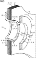
- FIG. 13 is a schematic sectional view of the lamella pack 30 of FIG FIG 1 shown first embodiment of the claimed clutch 10 is shown.
- a lamella pack 30 which comprises a plurality of lamellae 32, the lamella bores 34 of which are arranged in alignment with an assembly opening 36.
- the assembly opening 36 is designed to receive a bolt 20, not shown in detail.
- a bushing 40 is arranged in the assembly opening 36 and extends through the assembly opening 36.
- the bush 40 is provided with a collar 41 on one side of the disk pack 30, which collar allows the bush 40 to be supported against the disk pack 30.
- the collar 41 is molded on and formed in one piece with a first end region 44 of the bushing 40, which is located essentially on a side of the lamella set 30 facing away from the collar 41.
- a ring 42 which is detachably connected to the bush 40, is arranged on the first end region 44.
- the ring 42 has a latching nose 45 on an inner surface 53, which is formed in a latching groove 47 in the first end region 44 of the socket 40.
- the locking lug 45 and the locking groove 47 are at least partially circumferential and, due to their shape, produce a form fit 48.
- a clip connection 43 is thereby realized.
- FIG 1 Through the form fit 48 along an axial direction 29 that is essentially parallel to the main axis of rotation 15 FIG 1 is aligned, an unintentional dismantling of the connected items, that is to say the bush 40, the lamellae 32 and the ring 42 is prevented. For this purpose, a holding force 49 is exerted.
- FIG 3 shows schematically the first embodiment of the disk pack 30 of FIG FIG 1
- the illustrated claimed clutch 10 prior to a third step 130 of the manufacturing method 100 (not illustrated in more detail).
- FIG 3 assumes that a first step 110, in which the disk pack 30, the comprises a plurality of lamellae 32, is provided, is completed.
- a second step 120 in which a bushing 40 is inserted into the assembly openings 36 of the lamella set 30, has been completed.
- a ring 42 is provided, which is pushed onto a first end region 44 of the bushing 40 by an assembly force 33.
- FIG 4 Corresponding to FIG 3 is in FIG 4 the disk pack 30 of the first embodiment of the claimed clutch 10 is shown after the third step 130 has been carried out.
- the ring 42 After locking in the locking groove 47, the ring 42 is in contact with the first end area 44 of the socket 40 via the locking lug 45 in a contact area 52 Frictional connection 55 is caused.
- the contact area 52, and thus also the frictional connection 55 between the ring 42 and the bush 40, is at least partially circumferential.
- the ring 42 and the bushing 40 are made of a metallic material, so that a correspondingly high restoring force 23 is produced in them, which generate a correspondingly resilient force fit 55.
- the interaction of the form fit 48 and the force fit 55 offers a high degree of strength for the detachable connection of the ring 42 to the socket 40.
- the form fit 48 prevents the ring from falling off the socket.
- the frictional connection 55 causes a possibly Existing axial play of the positive connection does not lead directly to a vibration, i.e. a rattling, of the ring on the socket. Overall, a holding force 49 is exerted.
- FIG 5 a second embodiment of the disk pack 30 of the claimed clutch 10 is shown in a sectional oblique view.
- FIG 5 shows FIG 5 the first embodiment during a third step 130 of a production method 100 according to the invention.
- FIG 5 assumes that a first step 110, in which the plate pack 30, which comprises a plurality of plates 32, is provided, has been completed.
- FIG 5 also assumes that a second step 120, in which a bushing 40 with a collar 41 is inserted into the assembly openings 36 of the lamella set 30, has been completed.
- the assembly opening 36 is formed by a plurality of lamellar bores 36 which are arranged in alignment.
- a ring 42 is provided, which is pushed onto a first end region 44 of the bushing 40 by an assembly force 33.
- a locking groove 47 and a locking lug 45 are formed in a first end region 44 of the socket 40.
- the latching groove 47 and the latching lug 45 in the first end region 44 are spaced apart on the bushing 40 along a circumferential direction 51 by an alignment groove 35.
- a locking groove 47 and a locking nose 45 are formed on an inner surface 53 of the ring 42.
- the latching groove 47 and the latching nose 45 are spaced apart on the ring 42 by an alignment spring 37.
- the alignment groove 35 of the bushing 40 is designed to receive the alignment spring 37 of the ring 42.
- the alignment spring 37 can also be formed on the bushing 40 and the alignment groove 35 on the ring 42.
- a form fit 48 is produced by the locking lug 45 on the socket 40 and the locking groove 47 on the ring 42.
- a releasable connection, in particular a clip connection 43, is thus established between the ring 42 and the bushing 40.
- a plurality of rings 42 are on a corresponding one
- a plurality of bushings 40 on a disk pack 30 as in FIG FIG 5 shown can be installed at the same time.
- the assembly force 33 is exerted, for example, by a punch, not shown.
- FIG 6 shows a schematic detailed view of a third embodiment of the disk pack 30 of the claimed clutch 10.
- the disk pack 30 is shown in an assembled state and has a bushing 40 with a first end section 44 onto which a ring 42 is pushed.
- the bushing 40 is arranged in a mounting opening 36 which is formed by lamellar bores 34 arranged in alignment.
- the ring 42 rests against a disk pack 30, which comprises a plurality of disks 32.
- a locking lug 45 is formed which engages in a locking groove 47 on the ring 42.
- the locking lug 45 and the locking groove 47 produce a form fit 48 by means of which the ring 42 and the bushing 40 are held in position relative to one another.
- the locking lug 45 which rests under pressure in the locking groove 47 on an inner surface 53 of the ring 42 in a contact area 52, additionally generates a force fit 55.
- the ring 42 and the bushing 40 together form a detachable connection, in particular a clip connection 43.
- FIG 7 a schematic sectional view of a fourth embodiment of the disk set 30 of the claimed clutch 10.
- the disk set 30 has a plurality of disks 32.
- lamellae 32 there are lamellar bores 34 which are arranged in alignment.
- the lamellar bores 34 thus together form a mounting bore 36 which is designed to receive a bolt 20, not shown in detail.
- a bushing 40 is formed in the assembly opening 36 and has a first and a second end region 44, 46.
- a ring 42 is located on each of the two end regions 44, 46 attached, through which the bushing 40 is held on the disk pack 30.
- a latching groove 47 is formed which is formed circumferentially.
- the rings 42 each have a locking lug 45 on their inner surfaces 53, which is designed to correspond to the locking groove 47.
- the locking lug 45 and the locking groove 47 are locked into one another and form a form fit 48.
- the rings 42 and the bushing 40 each form a clip connection 43 at both end regions 44, 46.
- an assembly force 33 is exerted, by means of which the rings 42 and the bushing 40 mutually engage and thus implement the principle of a clip connection 43 and thus provide a detachable connection.
- the assembly force 33 exerts a holding force 49 on the disk pack 30.
- the embodiment according to FIG 7 is based with the bush 40 and the rings 42 on geometrically simple components that can be produced quickly and cost-effectively. The variety of components is limited in the manufacture of the clutch 10, which in turn leads to a simpler production.
- a fifth embodiment of the disk set 30 of the claimed clutch 10 is shown in a detailed view in FIG FIG 8 shown.
- the disk pack 30 has a plurality of disks 32 in which disk bores 34 are formed.
- the lamellar bores 34 are aligned and thus form an assembly opening 36 in which a bush 40 is received.
- a locking groove 47 is formed on a first end region 44 of the socket 40.
- a latching groove 47 is also formed on an inner surface 53 of the ring 42 and is arranged essentially opposite the latching groove 47 in the first end region 48 of the bushing 40.
- an intermediate ring 56 made from an elastomer or a metallic material.
- a restoring force 57 is exerted on the inner surface 53 of the ring 42 and the first end region 44 of the bushing 40 by the intermediate ring 56.
- the connection between the ring 42 and the bush 40 can be released by squeezing the intermediate ring 56.
- an assembly force 33 is exerted on the ring 42, which allows sufficient deformation of the intermediate ring 56.
- a force fit 55 is produced by the restoring force 57 of the intermediate ring 56.
- a holding force 49 is exerted on the disk pack 30 by the applied assembly force 33.
- FIG 9 a sequence of an embodiment of the claimed method 100 for producing a clutch 10 is shown schematically.
- the method 100 is based on a first method step 110 in which a disk pack 30 is provided which has a plurality of disks 32.
- the lamellae 32 have lamellae bores 34 which are arranged in alignment with the assembly openings 36.
- a lamella pack 30 has a plurality of assembly openings 36.
- a second method step 120 follows, in which sockets 40 are provided and inserted into the assembly openings 36.
- the sockets 40 can be used in the same orientation or in opposite directions.
- a third method step 130 follows, in which a ring 42 is provided for each bush 40. The rings 42 are pressed against the respective bush 40 at a first end region 44 of the bush 40 by an assembly force 33.
- the bushing 40 and the ring 42 are designed to be positively connected to one another, for example by means of a clip connection 43.
- a pressing force 49 is exerted on the plate pack 30.
- a form fit 48 is formed between the ring 42 and the socket 40.
- the assembly force 33 for the respective bushings 40 and rings 42 can be generated by means of a common punch.
- several bushings 40 are releasably connected to a ring 42 essentially simultaneously.
- method 100 is in accordance with FIG 9 easy and quick to do. Using method 100 to FIG 9 are in particular clutches 10 according to FIG. 1 to FIG. 8 manufacturable.
- FIG 10 shows schematically the structure of a claimed industrial application 60, which has a drive unit 62 and a mechanical application 64.
- the drive unit 62 provides a drive power 25 that is used to operate the mechanical application 64, which can be used, for example, as a mill, vertical mill, sugar mill, cement mill, rock crusher, conveyor belt, pump, roller press, apron conveyor, tube mill, rotary kiln, rotary mechanism, agitator, lifting device, garbage press or scrap press can be formed.
- the drive power 25 is fed via a first shaft 65 to a coupling 10, which in turn is connected to a second shaft 66.
- the coupling 10 together with the first and second shaft 65, 66 forms a shaft arrangement 58.
- the clutch 10 is designed according to one of the embodiments outlined above and / or can be produced according to one of the methods 100 described above.
- FIG 11 the structure of a stressed wind turbine 80 is shown schematically.
- the wind power plant 80 comprises a nacelle 71 to which a rotor 72 is attached.
- the rotor 72 is coupled in a torque-transmitting manner via a rotor shaft 74 to a gear 76 which is designed as a planetary gear.
- the transmission 76 is connected to a generator 75 to transmit torque.
- a clutch 10 is attached between the transmission 76 and the generator 75.
- the coupling 10 is designed according to one of the embodiments described above.
Abstract
Die Erfindung betrifft eine Kupplung (10), die eine Mehrzahl an Lamellen (32) umfasst, die ein Lamellenpaket (30) bilden. In den Lamellen (32) sind Lamellenbohrungen (34) ausgebildet, die zu zumindest einer Montageöffnung (36) fluchtend angeordnet sind. Erfindungsgemäß ist in der zumindest einen Montageöffnung (36) eine Buchse (40) aufgenommen ist, die in zumindest einem ersten Endbereich (44) formschlüssig mit einem Ring (42) verbindbar ist. Die Erfindung betrifft auch ein Verfahren (100) zum Herstellen einer solchen Kupplung (10). Ferner betrifft die Erfindung eine Wellenanordnung (58) mit einer ersten und einer zweiten Welle (65, 66), die mit einer entsprechenden Kupplung (10) drehmomentübertragend verbunden sind. Gleichermaßen betrifft die Erfindung eine Industrieapplikation (60), die über eine derartige Wellenanordnung (58) verfügt und eine Windkraftanlage (80), die über eine entsprechende Kupplung (10) verfügt.The invention relates to a clutch (10) which comprises a plurality of disks (32) which form a disk set (30). In the lamellas (32) there are lamellar bores (34) which are arranged in alignment with at least one assembly opening (36). According to the invention, a bushing (40) is received in the at least one assembly opening (36) and can be connected to a ring (42) in a form-fitting manner in at least one first end region (44). The invention also relates to a method (100) for producing such a coupling (10). The invention also relates to a shaft arrangement (58) with a first and a second shaft (65, 66) which are connected to a corresponding coupling (10) in a torque-transmitting manner. The invention also relates to an industrial application (60) which has such a shaft arrangement (58) and a wind power plant (80) which has a corresponding coupling (10).
Description
Die Erfindung betrifft eine Kupplung mit einem Lamellenpaket, bei dem zwischen einer Buchse und einem Ring in einer Montageöffnung eine verbesserte Verbindung ausgebildet ist. Die Erfindung betrifft auch ein Herstellungsverfahren für eine entsprechende Kupplung. Ferner betrifft die Erfindung eine Wellenanordnung, die über eine entsprechende Kupplung verfügt. Gleichermaßen betrifft die Erfindung eine Industrieapplikation, die mit einer solchen Wellenanordnung ausgestattet ist.The invention relates to a coupling with a disk pack, in which an improved connection is formed between a bushing and a ring in an assembly opening. The invention also relates to a manufacturing method for a corresponding coupling. The invention also relates to a shaft arrangement which has a corresponding coupling. The invention also relates to an industrial application which is equipped with such a shaft arrangement.
Die Druckschrift
Aus
In einer Vielzahl an Industrieanwendungen besteht Bedarf an leistungsfähigen Kupplungen, die kompakt und zuverlässig sind, wirtschaftlich herstellbar und einfach zu warten. Der Erfindung liegt die Aufgabe zugrunde, eine Kupplung bereitzustellen, die in zumindest einem der beschriebenen Punkte eine Verbesserung bietet.In a large number of industrial applications, there is a need for high-performance couplings that are compact and reliable, can be manufactured economically and are easy to maintain. The invention is based on the object of providing a clutch which offers an improvement in at least one of the points described.
Die Aufgabenstellung wird durch eine erfindungsgemäße Kupplung gelöst. Die Kupplung umfasst eine Mehrzahl an Lamellen, die dazu ausgebildet sind, im Betrieb der Kupplung Zugkräfte zu übertragen und so Drehmoment von einer ersten Kupplungsseite auf eine zweite Kupplungsseite zu übertragen. Die Lamellen sind gebündelt, also zu Lamellenpaketen zusammengefasst. In den Lamellen sind Lamellenbohrungen ausgebildet und die Lamellen im Lamellenpaket so angeordnet, dass die Lamellenbohrungen fluchten. Dadurch wird im Lamellenpaket zumindest eine Montageöffnung gebildet, über die das Lamellenpaket mit der ersten oder zweiten Kupplungsseite verbindbar ist. Die Verbindung zwischen dem Lamellenpaket und einer Kupplungsseite wird beispielsweise durch einen Bolzen gewährleistet. In der mindestens eine Montageöffnung ist eine Buchse aufgenommen, durch die sich im montierten Zustand ein Bolzen erstreckt. Die Buchse weist dementsprechend zumindest einen hohlzylindrischen Abschnitt auf. An einem ersten Endbereich, also an mindestens einem Ende des hohlzylindrischen Abschnitts, ist die Buchse formschlüssig mit einem Ring verbindbar. Die Buchse weist im Endbereich eine Form auf, die durch eine Montagekraft rückstellfähig, also im Wesentlichen elastisch, verformbar ist, und so ein Formschluss mit dem Ring erzeugt wird. Der so hervorgerufene Formschluss verhindert ein Trennen des Rings von der Buchse in eine Axialrichtung. Der Ring ist derart ausgebildet, dass dieser im montierten Zustand die Form der Buchse im jeweiligen ersten Endbereich im Wesentlichen zur Form einer Kragenbuchse ergänzt.The problem is solved by a coupling according to the invention. The clutch comprises a plurality of disks which are designed to transmit tensile forces during operation of the clutch and thus to transmit torque from a first clutch side to a second clutch side. The lamellas are bundled, i.e. combined to form lamella sets. Lamella bores are formed in the lamellae and the lamellae are arranged in the lamella pack so that the lamellae bores are aligned. As a result, at least one assembly opening is formed in the disk pack, via which the disk pack can be connected to the first or second clutch side. The connection between the disk pack and a clutch side is ensured, for example, by a bolt. In the at least one assembly opening, a bush is received, through which a bolt extends in the assembled state. The socket accordingly has at least one hollow cylindrical section. At a first end region, that is to say at least one end of the hollow cylindrical section, the socket can be connected to a ring in a form-fitting manner. In the end region, the socket has a shape which can be resiliently, ie essentially elastically, deformed by an assembly force, and thus a form fit with the ring is produced. The positive fit produced in this way prevents the ring from separating from the bushing in an axial direction. The ring is designed in such a way that, in the assembled state, it complements the shape of the bushing in the respective first end region essentially to form a collar bushing.
Eine formschlüssige Verbindung zwischen der Buchse und dem Ring erlaubt es, deren Montage und gegebenenfalls auch Demontage in einfacher Weise mit niedrigen Montagekräften durchzuführen. Dementsprechend können einfachere Werkzeuge genutzt werden, oder mit relativ geringem Aufwand mehrere Ringe mit Buchsen gleichzeitig verbunden werden. Folglich kann die Herstellung einer erfindungsgemäßen Kupplung schnell und kosteneffizient erfolgen. Durch die reduzierten Montagekräfte kann eine Demontage gleichermaßen einfach durchgeführt werden, was die Wartungsfreundlichkeit in einer Vielzahl an industriellen Applikationen steigert.A form-fitting connection between the bushing and the ring allows their assembly and, if necessary, also disassembly to be carried out in a simple manner with low assembly forces. Accordingly, simpler tools can be used, or several rings can be connected with bushings at the same time with relatively little effort. As a result, a coupling according to the invention can be produced quickly and cost-effectively. Due to the reduced assembly forces, dismantling can be carried out just as easily, what the ease of maintenance in a variety of industrial applications increases.
In der beanspruchten Kupplung können die Buchse und/oder der Ring zu einem lösbaren Verbinden verformbar ausgebildet sein. Bei einem Montage- oder Demontagevorgang kann also die Buchse derart verformt werden, dass der Ring über die Buchse geschoben werden kann. Dementsprechend kann auch der Ring beim Aufschieben auf die Buchse verformt werden. Ebenso ist auch eine Kombination von beidem möglich. Unter einem Verformen ist dabei ein im Wesentlichen elastisches Verformen zu verstehen, bei dem plastische Verformungsanteile bei einer einmaligen Montage vernachlässigbar sind. Dadurch kann eine Rückstellkraft im Ring und/oder der Buchse hervorgerufen werden.In the claimed coupling, the socket and / or the ring can be designed to be deformable for a releasable connection. During an assembly or disassembly process, the bush can be deformed in such a way that the ring can be pushed over the bush. Accordingly, the ring can also be deformed when it is pushed onto the socket. A combination of both is also possible. Deformation is to be understood as meaning essentially elastic deformation, in which plastic deformation components are negligible in the case of a single assembly. This can cause a restoring force in the ring and / or the socket.
Des Weiteren kann in einem montierten Zustand zwischen der Buchse und dem Ring ein Kraftschluss und/oder ein Formschluss vorliegen. Ein Kraftschluss kann beispielsweise zwischen einer Innenfläche des Rings und einer Außenfläche im Endbereich der Buchse vorliegen. Ein Formschluss wiederum kann beispielsweise durch eine Klippverbindung zwischen dem Ring und der Buchse hergestellt werden. Ein Formschluss weist eine reduzierte Relaxationsneigung auf und bietet so dauerhaft ein hohes Maß an Haltekraft. Eine Klippverbindung kann beispielsweise durch eine Rastnase an der Außenfläche der Buchse im entsprechenden Endbereich oder and er Innenfläche des Rings hergestellt werden. Ferner kann korrespondierend zur Rastnase an der Buchse oder dem Ring eine Rastnut ausgebildet sein. Derartige Klippverbindungen sind in einfacher Weise derart auslegbar, dass eine angestrebte Montagekraft einstellbar ist. Dabei können die sonstigen mechanischen Anforderungen an die Buchse bzw. den Ring unbeeinträchtigt bleiben. Dementsprechend ist die beanspruchte Lösung für eine Vielzahl an Anwendungsfällen einfach anpassbar. Des Weiteren erfolgt ein Einrasten einer Klippverbindung beim Montieren selbsttätig, was den Montagevorgang weiter vereinfacht. Darüber hinaus sind bei der Montage des Lamellenpakets der beanspruchten Kupplung größenspezifischen Werkzeuge, wie beispielsweise Anpresskegel zum Kaltverformen, entbehrlich.Furthermore, in an assembled state, a force fit and / or a form fit can be present between the bushing and the ring. A frictional connection can be present, for example, between an inner surface of the ring and an outer surface in the end region of the socket. A form fit, in turn, can be produced, for example, by a clip connection between the ring and the socket. A form fit has a reduced tendency to relax and thus offers a high level of holding power over the long term. A clip connection can be established, for example, by a latching lug on the outer surface of the socket in the corresponding end area or on the inner surface of the ring. Furthermore, a locking groove can be formed to correspond to the locking lug on the socket or the ring. Such clip connections can be designed in a simple manner in such a way that a desired assembly force can be set. The other mechanical requirements on the socket or ring can remain unaffected. Accordingly, the claimed solution can be easily adapted for a large number of applications. Furthermore, a clip connection engages automatically during assembly, which further simplifies the assembly process. In addition, when assembling the lamella set, the claimed Coupling size-specific tools, such as pressure cones for cold forming, are unnecessary.
In einer weiteren Ausführungsform der beanspruchten Kupplung können die Buchse und/oder der Ring aus einem metallischen Werkstoff hergestellt sein, beispielsweise einem Stahl, einer Stahllegierung, Kupfer, einer Kupferlegierung, Aluminium, oder einer Aluminiumlegierung. Metallische Werkstoffe bieten ein hohes Maß an Festigkeit und sind in erprobter Weise bearbeitbar. Ein metallischer Werkstoff ist insbesondere derart bearbeitbar, dass die Buchse und/oder der Ring im Bereich der formschlüssigen Verbindung, beispielsweise an der Innenfläche des Rings oder einem Endbereich der Buchse, derart weich sind, dass eine reduzierte Montagekraft erzielbar ist. Gleichzeitig sind die Buchse und/oder der Ring derart auslegbar, dass sie ansonsten ein hohes Maß an Stabilität bieten. Infolgedessen wird die reduzierte Montagekraft nicht zulasten der mechanischen Beanspruchbarkeit oder Zuverlässigkeit der Kupplung erzielt. Weiter alternativ können der Ring und/oder die Buchse einem Kunststoff hergestellt sein. Kunststoffe bieten eine geringe Dichte und sind kosteneffizient. Kunststoffe sind ferner elektrisch isolierend und erlauben es so, über die Kupplung miteinander verbundene Komponenten zu schützen, und so das Prinzip der Funktionsintegration zu verwirklichen.In a further embodiment of the claimed coupling, the bushing and / or the ring can be made of a metallic material, for example a steel, a steel alloy, copper, a copper alloy, aluminum, or an aluminum alloy. Metallic materials offer a high degree of strength and can be processed in a tried and tested manner. A metallic material can in particular be machined in such a way that the socket and / or the ring are so soft in the area of the positive connection, for example on the inner surface of the ring or an end area of the socket, that a reduced assembly force can be achieved. At the same time, the socket and / or the ring can be designed in such a way that they otherwise offer a high degree of stability. As a result, the reduced assembly force is not achieved at the expense of the mechanical strength or reliability of the coupling. As a further alternative, the ring and / or the socket can be made of plastic. Plastics offer low density and are cost effective. Plastics are also electrically insulating and thus make it possible to protect components connected to one another via the coupling and thus to implement the principle of functional integration.
In einer weiteren Ausführungsform der beanspruchten Kupplung weist die Buchse einseitig einen Kragen auf, der angeformt ist. Die Buchse kann somit als Kragenbuchse ausgebildet sein. Ein solcher Kragen erlaubt es, die Buchse einseitig gegen das Lamellenpaket abzustützen und durch Anbringen des Rings an dem Endbereich, der dem Kragen abgewandt ist, die Montage zu vervollständigen. Die Anzahl an erforderlichen Komponenten ist durch die Verwendung einer Buchse mit Kragen und eines Rings minimiert. Infolgedessen ist auch die Anzahl an Montageschritten reduziert.In a further embodiment of the claimed coupling, the socket has a collar on one side which is integrally formed. The socket can thus be designed as a collar socket. Such a collar makes it possible to support the bushing on one side against the lamella pack and to complete the assembly by attaching the ring to the end area facing away from the collar. The number of components required is minimized by using a collar and ring. As a result, the number of assembly steps is also reduced.
Alternativ kann die Buchse auch in einem ersten und einem zweiten Endbereich, also beidseitig, mit je einem Ring formschlüssig verbindbar ausgebildet sein. Zur Montage wird dementsprechend eine Buchse mit zwei Ringen formschlüssig verbunden. Die formschlüssigen Verbindungen zwischen der Buchse und den Ringen kann dabei im ersten und zweiten Endbereich auf gleiche Weise hergestellt werden. Dazu können Ringe, die am ersten und zweiten Endbereich der Buchse angebracht sind, baugleich, also untereinander austauschbar, ausgebildet sein. Dadurch ist die Anzahl an unterschiedlichen Bauteilen auch reduziert. Ferner stellt eine Buchse ohne Kragen ein relativ einfaches Bauteil dar, das schnell und kosteneffizient herstellbar ist. Infolgedessen kann die beanspruchte Lösung in besonders wirtschaftlicher Weise umgesetzt werden.Alternatively, the socket can also be designed to be positively connectable in a first and a second end area, that is to say on both sides, with one ring each. Accordingly, a socket is positively connected with two rings for assembly. The form-fitting connections between the socket and the rings can be produced in the same way in the first and second end regions. For this purpose, rings that are attached to the first and second end regions of the bushing can be constructed identically, that is to say interchangeable with one another. This also reduces the number of different components. Furthermore, a socket without a collar represents a relatively simple component that can be produced quickly and cost-effectively. As a result, the claimed solution can be implemented in a particularly economical manner.
Darüber hinaus kann im montierten Zustand zwischen der Buchse und dem Ring ein Zwischenring angeordnet sein. Der Zwischenring dient dabei zur Herstellung des Kraftschlusses und/oder des Formschlusses zwischen der Buchse und dem Ring. Der Zwischenring kann beispielsweise aus einem Elastomer hergestellt sein und bei der Montage auf dem entsprechenden Endbereich der Buchse oder an der Innenfläche des Rings angeordnet werden. Insbesondere kann der Zwischenring in einer Rastnut positioniert sein, die im Endbereich der Buchse bzw. an der Innenfläche des Rings ausgebildet ist. Zusätzlich kann der Zwischenring als Dichtung dienen. Der Zwischenring ist gezielt als Verschleißteil einsetzbar, so dass bei einer Wiedermontage der Kupplung eine Schädigung oder Degradation der Buchse und/oder des Rings ausschließbar ist. Der Zwischenring kann aus einem metallischen Werkstoff hergestellt sein oder aus einem Kunststoff, beispielsweise einem Elastomer. Zwischenringe aus einem metallischen Werkstoff sind mit hoher Präzision herstellbar und sind langlebig. Kunststoffe hingegen sind kosteneffizient und deshalb besonders als Verschleißteile geeignet.In addition, an intermediate ring can be arranged between the bushing and the ring in the assembled state. The intermediate ring is used to produce the force fit and / or the form fit between the socket and the ring. The intermediate ring can, for example, be made of an elastomer and, during assembly, can be arranged on the corresponding end region of the bushing or on the inner surface of the ring. In particular, the intermediate ring can be positioned in a latching groove which is formed in the end region of the bush or on the inner surface of the ring. In addition, the intermediate ring can serve as a seal. The intermediate ring can be used specifically as a wear part, so that when the coupling is reassembled, damage or degradation of the bushing and / or the ring can be ruled out. The intermediate ring can be made from a metallic material or from a plastic, for example an elastomer. Intermediate rings made of a metallic material can be manufactured with high precision and have a long service life. Plastics, on the other hand, are cost-efficient and therefore particularly suitable as wear parts.
Ferner kann der Ring mit der Buchse mittels einer Montagekraft, also einer Andrückkraft, von bis zu 15 kN, bevorzugt von bis zu 10 kN, weiter bevorzugt von bis zu 8 kN, besonders bevorzugt von bis zu 6,5 kN verbunden werden. Derartige Montagekräfte können bereits beispielsweise durch einfache hydraulische Werkzeuge oder elektrisch betätigte Maschinen ausgeübt werden. Die beanspruchte Lösung kann, wie oben skizziert, in einfacher Weise in puncto Montagekraft konstruktiv ausgelegt werden. Dementsprechend werden an die Herstellung der beanspruchten Kupplung nur geringe Anforderungen gestellt.Furthermore, the ring with the bushing can be preferred by means of an assembly force, that is to say a pressing force, of up to 15 kN of up to 10 kN, more preferably of up to 8 kN, particularly preferably of up to 6.5 kN. Such assembly forces can already be exerted, for example, by simple hydraulic tools or electrically operated machines. As outlined above, the claimed solution can be designed in a simple manner in terms of assembly force. Accordingly, only low requirements are placed on the production of the claimed coupling.
Darüber hinaus kann die Buchse mit einer Ausrichtnut und/oder einer Ausrichtfeder versehen sein. Durch die Ausrichtnut bzw. Ausrichtfeder wird die Rastnase oder Rastnut im Endbereich der Buchse, in Umfangsrichtung betrachtet, unterbrochen. Alternativ oder ergänzend kann der Ring mit einer Ausrichtnut und/oder Ausrichtfeder versehen sein. Insbesondere können zumindest eine Ausrichtnut und zumindest eine Ausrichtfeder des Rings bzw. der Buchse zueinander korrespondierend ausgebildet sein. Dadurch wird im montierten Zustand eine exakte Winkelposition des Rings gegenüber der Buchse gewährleistet. Ferner können die Ausrichtnut und/oder Ausrichtfeder zwischen einer Rastnut und einer Rastnase im Endbereich der Buchse angeordnet sein. Dadurch unterbrechen die Ausrichtnut bzw. Ausrichtfeder entlang der Umfangsrichtung eine alternierende Abfolge zumindest einer Rastnut und einer Rastfeder. Korrespondierend hierzu kann der Ring an seiner Innenfläche auch mit zumindest einer Rastnut und einer Rastfeder ausgestattet sein, zwischen denen eine Ausrichtnut oder Ausrichtfeder positioniert sind.In addition, the socket can be provided with an alignment groove and / or an alignment spring. The locking lug or locking groove in the end region of the socket, viewed in the circumferential direction, is interrupted by the alignment groove or alignment spring. As an alternative or in addition, the ring can be provided with an alignment groove and / or alignment spring. In particular, at least one alignment groove and at least one alignment spring of the ring or the socket can be designed to correspond to one another. This ensures an exact angular position of the ring with respect to the socket in the assembled state. Furthermore, the alignment groove and / or alignment spring can be arranged between a locking groove and a locking lug in the end region of the socket. As a result, the alignment groove or alignment spring interrupts an alternating sequence of at least one latching groove and one latching spring along the circumferential direction. Corresponding to this, the ring can also be equipped on its inner surface with at least one locking groove and one locking spring, between which an alignment groove or alignment spring is positioned.
Die zugrundeliegende Aufgabenstellung wird auch durch das erfindungsgemäße Herstellungsverfahren gelöst. Das erfindungsgemäße Verfahren umfasst einen ersten Schritt, in dem ein Lamellenpaket bereitgestellt wird, das eine Mehrzahl an Montageöffnungen aufweist, von denen zumindest mehrere mit einer Buchse zu versehen sind. In einem zweiten Schritt werden die Buchsen in die entsprechenden Montageöffnungen eingesetzt. Es wird auch ein dritter Verfahrensschritt durchgeführt, in dem jede der Buchsen mit einem Ring verbunden wird. Dazu werden die Ringe an die Buchsen angedrückt. Erfindungsgemäß wird zwischen den Buchsen und den jeweiligen Ringen eine formschlüssige Verbindung hergestellt. Durch das erfindungsgemäße Verfahren sind Lamellenpakete für Kupplungen gemäß zumindest einer der oben skizzierten Ausführungsformen herstellbar. Die Merkmale der beanspruchten Kupplungen sind deshalb auf das erfindungsgemäße Verfahren übertragbar.The underlying object is also achieved by the production method according to the invention. The method according to the invention comprises a first step in which a disk pack is provided which has a plurality of assembly openings, at least several of which are to be provided with a bushing. In a second step, the sockets are inserted into the corresponding assembly openings. A third process step is also carried out in which each of the sockets is connected to a ring. To be the rings pressed against the sockets. According to the invention, a positive connection is established between the sockets and the respective rings. With the method according to the invention, disk packs for clutches according to at least one of the embodiments outlined above can be produced. The features of the claimed clutches can therefore be transferred to the method according to the invention.
In einer Ausführungsform des beanspruchten Verfahrens werden im dritten Verfahrensschritt die Ringe im Wesentlichen gleichzeitig mit den jeweiligen Buchsen formschlüssig verbunden. Dazu können beispielsweise mehrere Ringe mit einem Stempel an die Buchsen angedrückt werden. Ebenso können auch die Buchsen durch einen Stempel an die Ringe angedrückt werden. Die Herstellung der Kupplung wird durch das im Wesentlichen gleichzeitige Verbinden von Buchsen und Ringen beschleunigt und vereinfacht. Insbesondere wird dadurch die Wirtschaftlichkeit bei der Herstellung von Kupplungen mit einer hohen Anzahl an Montageöffnungen gesteigert. Darüber hinaus sind beim beanspruchten Verfahren größenspezifische Werkzeug, wie beispielsweise Anpresskegel zum Kaltverformen, entbehrlich. Infolgedessen ist das beanspruchte Verfahren mit einem reduzierten Werkzeugaufwand schnell durchführbar. Ferner können Lamellenpakete unterschiedlicher Größen schnell hintereinander ohne Umrüstaufwand produziert werden. Das beanspruchte Verfahren ist daher flexibel, was eine erhöhte Produktivität bei der Herstellung von Kupplungen bietet.In one embodiment of the claimed method, in the third method step, the rings are connected in a form-fitting manner essentially simultaneously with the respective bushings. For this purpose, for example, several rings can be pressed onto the sockets with a stamp. The sockets can also be pressed onto the rings by a stamp. The production of the coupling is accelerated and simplified by the essentially simultaneous connection of bushings and rings. In particular, this increases the economic efficiency in the production of couplings with a large number of assembly openings. In addition, size-specific tools, such as pressure cones for cold forming, are unnecessary in the claimed method. As a result, the claimed method can be carried out quickly with a reduced outlay on tools. Furthermore, disk packs of different sizes can be produced quickly one after the other without the need for conversion. The claimed method is therefore flexible, which offers increased productivity in the manufacture of couplings.
In einer weiteren Ausführungsform des beanspruchten Verfahrens ist zumindest eine der formschlüssigen Verbindungen, die zwischen den Buchsen und den entsprechenden Ringen ausgebildet wird, als lösbare Verbindung ausgebildet. Unter einer lösbaren Verbindung zwischen der Buchse und dem Ring ist eine Verbindung zu verstehen, nach deren Lösen die Buchse und/oder der Ring wiederverwendbar ist. Dies kann beispielsweise eine Klippverbindung sein. Durch eine lösbare Verbindung können die nach dem beanspruchten Verfahren hergestellten Kupplungen besonders einfach inspiziert und repariert werden.In a further embodiment of the claimed method, at least one of the form-fitting connections that is formed between the sockets and the corresponding rings is designed as a releasable connection. A releasable connection between the bushing and the ring is to be understood as a connection, after the release of which the bushing and / or the ring can be reused. This can be a clip connection, for example. With a releasable connection, the couplings produced according to the claimed method can be inspected and repaired particularly easily.
Ebenso wird die zugrundeliegende Aufgabenstellung durch die erfindungsgemäße Wellenanordnung gelöst. Die Wellenanordnung umfasst eine erste Welle, die mit einer zweiten Welle über eine Kupplung verbunden ist. Durch die Kupplung wird eine Übertragung von Drehmoment von der ersten auf die zweite Welle oder umgekehrt gewährleistet. Die Kupplung, die die erste und zweite Welle verbindet, ist dabei nach einer der oben skizzierten Ausführungsformen ausgebildet. Durch die Verwendung der beanspruchten Kupplung ist die erfindungsgemäße Wellenanordnung kosteneffizient herstellbar, einfach inspizierbar und reparierbar.The underlying object is also achieved by the shaft arrangement according to the invention. The shaft arrangement comprises a first shaft which is connected to a second shaft via a coupling. The coupling ensures a transmission of torque from the first to the second shaft or vice versa. The coupling that connects the first and second shaft is designed according to one of the embodiments outlined above. By using the claimed coupling, the shaft arrangement according to the invention can be manufactured cost-effectively, can be easily inspected and repaired.
Gleichermaßen wird die eingangs dargestellte Aufgabenstellung durch die erfindungsgemäße Industrieapplikation gelöst. Die Industrieapplikation umfasst eine Antriebseinheit, die beispielsweise als Elektromotor, Verbrennungsmotor oder Hydraulikmotor ausgebildet sein kann. Die Antriebseinheit verfügt über eine erste Welle, über die eine von der Antriebseinheit erzeugt Antriebsleistung bereitgestellt wird. Ebenso weist die Industrieapplikation eine mechanische Anwendung auf, die beispielweise als Mühle, Vertikalmühle, Zuckermühle, Zementmühle, Gesteinsbrecher, Förderband, Pumpe, Rollenpresse, Plattenband, Rohrmühle, Drehrohrofen, Drehwerk, Rührwerk, Hubvorrichtung Müllpresse oder Schrottpresse ausgebildet sein kann. Die mechanische Anwendung weist eine zweite Welle auf, die dazu ausgebildet ist, die für den Betrieb notwendige Antriebsleistung der mechanischen Anwendung zumindest teilweise zuzuführen. Die erste und zweite Welle sind über eine Kupplung drehmomentübertragend miteinander verbunden. Infolgedessen wird von der Antriebseinheit bereitgestellte Antriebsleistung der mechanischen Anwendung zugeführt. Die erste und zweite Welle und die Kupplung gehören zu einer Wellenanordnung, die erfindungsgemäß nach einer der oben dargestellten Ausführungsformen ausgebildet ist. Die durch die Wellenanordnung erzielten Vorteile werden so auf den Betrieb der Industrieapplikation übertragen. Insbesondere ermöglicht die einfache Reparierbarkeit der Kupplung es, die Stillstandzeiten der Industrieapplikation zu minimieren und so deren Wirtschaftlichkeit zu steigern.The task presented at the beginning is likewise achieved by the industrial application according to the invention. The industrial application includes a drive unit that can be designed as an electric motor, internal combustion engine or hydraulic motor, for example. The drive unit has a first shaft via which a drive power generated by the drive unit is provided. The industrial application also has a mechanical application that can be designed, for example, as a mill, vertical mill, sugar mill, cement mill, rock crusher, conveyor belt, pump, roller press, apron conveyor, tube mill, rotary kiln, rotating mechanism, agitator, lifting device, garbage press or scrap press. The mechanical application has a second shaft which is designed to at least partially supply the drive power required for operation of the mechanical application. The first and second shafts are connected to one another in a torque-transmitting manner via a coupling. As a result, the drive power provided by the drive unit is supplied to the mechanical application. The first and second shaft and the coupling belong to a shaft arrangement which, according to the invention, is designed according to one of the embodiments presented above. The advantages achieved by the shaft arrangement are thus transferred to the operation of the industrial application. In particular, the simple repairability of the coupling makes it possible to reduce the downtimes of the To minimize industrial applications and thus to increase their profitability.
Die zugrundeliegende Aufgabenstellung wird auch durch eine erfindungsgemäße Windkraftanlage gelöst. Die Windkraftanlage weist einen Rotor auf, der drehmomentübertragend mit einer Rotorwelle verbunden ist, die in einer Gondel aufgenommen ist. Die Rotorwelle gehört zu einem Antriebsstrang, der auch einen Generator umfasst. Zusätzlich kann mechanisch zwischen den Generator und die Rotorwelle ein Getriebe, insbesondere ein mehrstufiges Planetengetriebe, geschaltet sein, das dann auch zum Antriebsstrang gehört. Zwischen der Rotorwelle und dem Generator ist erfindungsgemäß eine Kupplung angeordnet, die Komponenten des Antriebsstrangs drehmomentübertragend verbindet. Die Kupplung kann dabei beispielsweise unmittelbar zwischen dem Generator und der Rotorwelle, zwischen der Rotorwelle und dem Getriebe, oder zwischen dem Getriebe und dem Generator angebracht sein. Die beanspruchte Kupplung ist dabei kosteneffizient und weist eine gesteigerte Wartungs- und Reparaturfreundlichkeit auf.The underlying problem is also achieved by a wind power plant according to the invention. The wind power plant has a rotor which is connected in a torque-transmitting manner to a rotor shaft which is accommodated in a nacelle. The rotor shaft is part of a drive train that also includes a generator. In addition, a gear, in particular a multi-stage planetary gear, which then also belongs to the drive train, can be connected mechanically between the generator and the rotor shaft. According to the invention, a coupling is arranged between the rotor shaft and the generator which connects components of the drive train in a torque-transmitting manner. The clutch can for example be attached directly between the generator and the rotor shaft, between the rotor shaft and the gearbox, or between the gearbox and the generator. The claimed coupling is cost-effective and is easier to maintain and repair.
Die Erfindung wird im Folgenden anhand einzelner Ausführungsformen beschrieben. Die Merkmale der einzelnen Ausführungsformen sind dabei untereinander kombinierbar. Die Figuren sind insoweit in gegenseitiger Ergänzung zu lesen, dass gleiche Bezugszeichen in den Figuren auch die gleichen technischen Bedeutungen haben. Es zeigen im Einzelnen:
- FIG 1
- eine schematische Schrägansicht einer ersten Ausführungsform der beanspruchten Kupplung;
- FIG 2
- eine schematische Detail-Schnittansicht der ersten Ausführungsform der beanspruchten Kupplung;
- FIG 3
- eine Detailansicht der ersten Ausführungsform der beanspruchten Kupplung vor einem Schritt des beanspruchten Herstellungsverfahrens;
- FIG 4
- eine Detailansicht der ersten Ausführungsform der beanspruchten Kupplung nach einem Schritt des beanspruchten Herstellungsverfahrens;
- FIG 5
- eine schematische Schrägansicht einer ersten Ausführungsform der beanspruchten Kupplung während vor einem Schritt des beanspruchten Herstellungsverfahrens;
- FIG 6
- eine schematische Detailansicht einer dritten Ausführungsform der beanspruchten Kupplung;
- FIG 7
- eine schematische Schnittansicht einer vierten Ausführungsform der beanspruchten Kupplung;
- FIG 8
- eine Detailansicht einer fünften Ausführungsform der beanspruchten Kupplung;
- FIG 9
- einen schematischen Ablauf einer Ausführungsform des beanspruchten Herstellungsverfahrens;
- FIG 10
- einen schematischen Aufbau einer erfindungsgemäßen Industrieapplikation mit einem erfindungsgemäßen Wellenanordnung;
- FIG 11
- einen schematischen Aufbau einer erfindungsgemäßen Windkraftanlage mit einer erfindungsgemäßen Kupplung;
- FIG 1
- a schematic oblique view of a first embodiment of the claimed coupling;
- FIG 2
- a schematic detailed sectional view of the first embodiment of the claimed coupling;
- FIG 3
- a detailed view of the first embodiment of the claimed coupling before a step of the claimed manufacturing method;
- FIG 4
- a detailed view of the first embodiment of the claimed coupling after a step of the claimed manufacturing method;
- FIG 5
- a schematic oblique view of a first embodiment of the claimed coupling during a step of the claimed manufacturing method;
- FIG 6
- a schematic detailed view of a third embodiment of the claimed coupling;
- FIG 7
- a schematic sectional view of a fourth embodiment of the claimed coupling;
- FIG 8
- a detailed view of a fifth embodiment of the claimed coupling;
- FIG 9
- a schematic sequence of an embodiment of the claimed manufacturing method;
- FIG 10
- a schematic structure of an industrial application according to the invention with a shaft arrangement according to the invention;
- FIG 11
- a schematic structure of a wind turbine according to the invention with a clutch according to the invention;
In
Korrespondierend zu
In
Die
Ferner zeigt
Eine fünfte Ausführungsform des Lamellenpakets 30 der beanspruchten Kupplung 10 ist in einer Detailansicht in
In
In
Claims (15)
Priority Applications (3)
| Application Number | Priority Date | Filing Date | Title |
|---|---|---|---|
| EP19163960.8A EP3712453B1 (en) | 2019-03-20 | 2019-03-20 | Coupling with improved sleeve-ring connection |
| US16/824,412 US11598378B2 (en) | 2019-03-20 | 2020-03-19 | Coupling with improved bush-ring connection |
| CN202010196344.XA CN111720452B (en) | 2019-03-20 | 2020-03-19 | Coupling with improved sleeve ring connection |
Applications Claiming Priority (1)
| Application Number | Priority Date | Filing Date | Title |
|---|---|---|---|
| EP19163960.8A EP3712453B1 (en) | 2019-03-20 | 2019-03-20 | Coupling with improved sleeve-ring connection |
Publications (2)
| Publication Number | Publication Date |
|---|---|
| EP3712453A1 true EP3712453A1 (en) | 2020-09-23 |
| EP3712453B1 EP3712453B1 (en) | 2021-11-03 |
Family
ID=65904054
Family Applications (1)
| Application Number | Title | Priority Date | Filing Date |
|---|---|---|---|
| EP19163960.8A Active EP3712453B1 (en) | 2019-03-20 | 2019-03-20 | Coupling with improved sleeve-ring connection |
Country Status (3)
| Country | Link |
|---|---|
| US (1) | US11598378B2 (en) |
| EP (1) | EP3712453B1 (en) |
| CN (1) | CN111720452B (en) |
Citations (7)
| Publication number | Priority date | Publication date | Assignee | Title |
|---|---|---|---|---|
| US4055966A (en) * | 1975-10-10 | 1977-11-01 | Rexnord, Inc. | Torque transmission coupling |
| DE3621188A1 (en) | 1986-06-25 | 1988-01-21 | Loehr & Bromkamp Gmbh | Flexible coupling |
| DE4227476C1 (en) * | 1992-08-20 | 1993-09-09 | Maschinenfabrik Moenninghoff Gmbh & Co Kg, 4630 Bochum, De | Shaft coupling with two connecting flanges and interposed multi-plate assembly - has specially dimensioned screw bolt shaft cylinder sections associated with centring bushes for play-free support. |
| DE19742361A1 (en) * | 1997-09-25 | 1999-04-22 | Sgf Gmbh & Co Kg | Elastic joint body |
| US20100099505A1 (en) | 2006-03-13 | 2010-04-22 | Corey Dennis J | Unitized Disc Pack And Disc Pack Coupling Formed Therewith |
| US7871331B2 (en) * | 2005-01-25 | 2011-01-18 | SGF Suddeutshe Gelenksheibenfabrik GmbH & Co. KG | Elastic joint member |
| DE202011110002U1 (en) * | 2011-03-25 | 2012-09-17 | Chr. Mayr Gmbh & Co. Kg | Slat connection for torsionally stiff elastic all-steel shaft coupling |
Family Cites Families (7)
| Publication number | Priority date | Publication date | Assignee | Title |
|---|---|---|---|---|
| DE3641547C1 (en) * | 1986-12-05 | 1988-07-14 | Atec Weiss Kg | Flexible all-steel shaft coupling |
| DE29604608U1 (en) * | 1996-03-12 | 1996-05-02 | Mayr Christian Gmbh & Co Kg | Torsionally rigid, flexible shaft coupling, especially made of all-steel |
| US6452287B1 (en) * | 1999-06-14 | 2002-09-17 | Ivan Looker | Windmill and method to use same to generate electricity, pumped air or rotational shaft energy |
| JP3850209B2 (en) * | 2000-06-07 | 2006-11-29 | 株式会社日立製作所 | Power transmission shaft for vehicles |
| DE102006009594A1 (en) * | 2006-03-02 | 2007-09-13 | Chr. Mayr Gmbh + Co Kg | Torsionally rigid flexible shaft coupling, in particular all-steel coupling |
| TWM394726U (en) | 2010-07-28 | 2010-12-21 | Jin-Sheng Lin | Protection cover having the externally-connected amplifier member |
| ES2773037T3 (en) * | 2017-04-07 | 2020-07-09 | Flender Gmbh | Multiple Disc Clutch |
-
2019
- 2019-03-20 EP EP19163960.8A patent/EP3712453B1/en active Active
-
2020
- 2020-03-19 US US16/824,412 patent/US11598378B2/en active Active
- 2020-03-19 CN CN202010196344.XA patent/CN111720452B/en active Active
Patent Citations (8)
| Publication number | Priority date | Publication date | Assignee | Title |
|---|---|---|---|---|
| US4055966A (en) * | 1975-10-10 | 1977-11-01 | Rexnord, Inc. | Torque transmission coupling |
| US4055966B1 (en) * | 1975-10-10 | 1977-11-01 | ||
| DE3621188A1 (en) | 1986-06-25 | 1988-01-21 | Loehr & Bromkamp Gmbh | Flexible coupling |
| DE4227476C1 (en) * | 1992-08-20 | 1993-09-09 | Maschinenfabrik Moenninghoff Gmbh & Co Kg, 4630 Bochum, De | Shaft coupling with two connecting flanges and interposed multi-plate assembly - has specially dimensioned screw bolt shaft cylinder sections associated with centring bushes for play-free support. |
| DE19742361A1 (en) * | 1997-09-25 | 1999-04-22 | Sgf Gmbh & Co Kg | Elastic joint body |
| US7871331B2 (en) * | 2005-01-25 | 2011-01-18 | SGF Suddeutshe Gelenksheibenfabrik GmbH & Co. KG | Elastic joint member |
| US20100099505A1 (en) | 2006-03-13 | 2010-04-22 | Corey Dennis J | Unitized Disc Pack And Disc Pack Coupling Formed Therewith |
| DE202011110002U1 (en) * | 2011-03-25 | 2012-09-17 | Chr. Mayr Gmbh & Co. Kg | Slat connection for torsionally stiff elastic all-steel shaft coupling |
Also Published As
| Publication number | Publication date |
|---|---|
| US20200300393A1 (en) | 2020-09-24 |
| EP3712453B1 (en) | 2021-11-03 |
| CN111720452B (en) | 2022-04-19 |
| CN111720452A (en) | 2020-09-29 |
| US11598378B2 (en) | 2023-03-07 |
Similar Documents
| Publication | Publication Date | Title |
|---|---|---|
| DE102013006858B4 (en) | Hybrid powertrain device for a motor vehicle | |
| EP2913554B2 (en) | Spring package, coupling and coupling production method | |
| EP1686276B1 (en) | Twin clutch with partition wall | |
| DE102017104446A1 (en) | Multiple clutch device and hybrid module for a motor vehicle | |
| WO2007112722A1 (en) | Radial flow chamber for clutches in a clutch module | |
| DE102017125845A1 (en) | Hybrid module for the drive train of a motor vehicle | |
| EP1686277B1 (en) | Dual-clutch with same dimension disks | |
| DE102017111858B4 (en) | Hybrid module and drive arrangement for a motor vehicle | |
| EP3789625A1 (en) | Flange arrangement, flanged hub, locking means, gearbox, electric motor, wind power station and industrial application | |
| EP3719335A1 (en) | Laminate, method for producing same, laminate coupling and industrial application | |
| DE102018009252A1 (en) | Triple clutch device and drive train with such a triple clutch device | |
| DE102018211374A1 (en) | Rotor carrier for an electrical machine | |
| EP3712453B1 (en) | Coupling with improved sleeve-ring connection | |
| EP3521648B1 (en) | Multi-plate clutch comprising improved axial offset stop and industry application | |
| DE102016216704A1 (en) | shaft coupling | |
| DE202008012129U1 (en) | Coupling arrangement with two axially successively arranged coupling elements | |
| DE202011110002U1 (en) | Slat connection for torsionally stiff elastic all-steel shaft coupling | |
| DE102009036746A1 (en) | Method for assembling bearing support of intermediate bearing for mounting triply-supported drive shaft of manual transmission of e.g. passenger car, involves rotating wheel set, and screwing transmission housing halves with each other | |
| EP2742252B1 (en) | Stator for a friction clutch | |
| EP3056754A1 (en) | Starting unit for a drive train of a motor vehicle | |
| WO2018161997A1 (en) | Intermediate shaft as support for clutch assemblies | |
| DE102010051907B4 (en) | Method for producing a backlash-free connection between two components to be arranged coaxially to one another, in particular a hub and a disk-shaped element | |
| EP2551553A1 (en) | Gearbox assembly | |
| EP3647618B1 (en) | Improved lamellae connection for a lamellar coupling and industrial application | |
| DE102020212446A1 (en) | Coupling with improved shaft connection and industrial application |
Legal Events
| Date | Code | Title | Description |
|---|---|---|---|
| PUAI | Public reference made under article 153(3) epc to a published international application that has entered the european phase |
Free format text: ORIGINAL CODE: 0009012 |
|
| STAA | Information on the status of an ep patent application or granted ep patent |
Free format text: STATUS: THE APPLICATION HAS BEEN PUBLISHED |
|
| AK | Designated contracting states |
Kind code of ref document: A1 Designated state(s): AL AT BE BG CH CY CZ DE DK EE ES FI FR GB GR HR HU IE IS IT LI LT LU LV MC MK MT NL NO PL PT RO RS SE SI SK SM TR |
|
| AX | Request for extension of the european patent |
Extension state: BA ME |
|
| STAA | Information on the status of an ep patent application or granted ep patent |
Free format text: STATUS: REQUEST FOR EXAMINATION WAS MADE |
|
| 17P | Request for examination filed |
Effective date: 20210119 |
|
| RBV | Designated contracting states (corrected) |
Designated state(s): AL AT BE BG CH CY CZ DE DK EE ES FI FR GB GR HR HU IE IS IT LI LT LU LV MC MK MT NL NO PL PT RO RS SE SI SK SM TR |
|
| RIC1 | Information provided on ipc code assigned before grant |
Ipc: F16D 3/79 20060101ALI20210202BHEP Ipc: F16D 3/78 20060101AFI20210202BHEP |
|
| GRAP | Despatch of communication of intention to grant a patent |
Free format text: ORIGINAL CODE: EPIDOSNIGR1 |
|
| STAA | Information on the status of an ep patent application or granted ep patent |
Free format text: STATUS: GRANT OF PATENT IS INTENDED |
|
| GRAJ | Information related to disapproval of communication of intention to grant by the applicant or resumption of examination proceedings by the epo deleted |
Free format text: ORIGINAL CODE: EPIDOSDIGR1 |
|
| STAA | Information on the status of an ep patent application or granted ep patent |
Free format text: STATUS: REQUEST FOR EXAMINATION WAS MADE |
|
| INTG | Intention to grant announced |
Effective date: 20210510 |
|
| INTC | Intention to grant announced (deleted) | ||
| GRAP | Despatch of communication of intention to grant a patent |
Free format text: ORIGINAL CODE: EPIDOSNIGR1 |
|
| STAA | Information on the status of an ep patent application or granted ep patent |
Free format text: STATUS: GRANT OF PATENT IS INTENDED |
|
| INTG | Intention to grant announced |
Effective date: 20210728 |
|
| GRAS | Grant fee paid |
Free format text: ORIGINAL CODE: EPIDOSNIGR3 |
|
| GRAA | (expected) grant |
Free format text: ORIGINAL CODE: 0009210 |
|
| STAA | Information on the status of an ep patent application or granted ep patent |
Free format text: STATUS: THE PATENT HAS BEEN GRANTED |
|
| AK | Designated contracting states |
Kind code of ref document: B1 Designated state(s): AL AT BE BG CH CY CZ DE DK EE ES FI FR GB GR HR HU IE IS IT LI LT LU LV MC MK MT NL NO PL PT RO RS SE SI SK SM TR |
|
| REG | Reference to a national code |
Ref country code: GB Ref legal event code: FG4D Free format text: NOT ENGLISH |
|
| REG | Reference to a national code |
Ref country code: AT Ref legal event code: REF Ref document number: 1444217 Country of ref document: AT Kind code of ref document: T Effective date: 20211115 Ref country code: CH Ref legal event code: EP |
|
| REG | Reference to a national code |
Ref country code: IE Ref legal event code: FG4D Free format text: LANGUAGE OF EP DOCUMENT: GERMAN |
|
| REG | Reference to a national code |
Ref country code: DE Ref legal event code: R096 Ref document number: 502019002622 Country of ref document: DE |
|
| REG | Reference to a national code |
Ref country code: LT Ref legal event code: MG9D |
|
| REG | Reference to a national code |
Ref country code: NL Ref legal event code: MP Effective date: 20211103 |
|
| PG25 | Lapsed in a contracting state [announced via postgrant information from national office to epo] |
Ref country code: RS Free format text: LAPSE BECAUSE OF FAILURE TO SUBMIT A TRANSLATION OF THE DESCRIPTION OR TO PAY THE FEE WITHIN THE PRESCRIBED TIME-LIMIT Effective date: 20211103 Ref country code: LT Free format text: LAPSE BECAUSE OF FAILURE TO SUBMIT A TRANSLATION OF THE DESCRIPTION OR TO PAY THE FEE WITHIN THE PRESCRIBED TIME-LIMIT Effective date: 20211103 Ref country code: FI Free format text: LAPSE BECAUSE OF FAILURE TO SUBMIT A TRANSLATION OF THE DESCRIPTION OR TO PAY THE FEE WITHIN THE PRESCRIBED TIME-LIMIT Effective date: 20211103 Ref country code: BG Free format text: LAPSE BECAUSE OF FAILURE TO SUBMIT A TRANSLATION OF THE DESCRIPTION OR TO PAY THE FEE WITHIN THE PRESCRIBED TIME-LIMIT Effective date: 20220203 |
|
| PG25 | Lapsed in a contracting state [announced via postgrant information from national office to epo] |
Ref country code: IS Free format text: LAPSE BECAUSE OF FAILURE TO SUBMIT A TRANSLATION OF THE DESCRIPTION OR TO PAY THE FEE WITHIN THE PRESCRIBED TIME-LIMIT Effective date: 20220303 Ref country code: SE Free format text: LAPSE BECAUSE OF FAILURE TO SUBMIT A TRANSLATION OF THE DESCRIPTION OR TO PAY THE FEE WITHIN THE PRESCRIBED TIME-LIMIT Effective date: 20211103 Ref country code: PT Free format text: LAPSE BECAUSE OF FAILURE TO SUBMIT A TRANSLATION OF THE DESCRIPTION OR TO PAY THE FEE WITHIN THE PRESCRIBED TIME-LIMIT Effective date: 20220303 Ref country code: PL Free format text: LAPSE BECAUSE OF FAILURE TO SUBMIT A TRANSLATION OF THE DESCRIPTION OR TO PAY THE FEE WITHIN THE PRESCRIBED TIME-LIMIT Effective date: 20211103 Ref country code: NO Free format text: LAPSE BECAUSE OF FAILURE TO SUBMIT A TRANSLATION OF THE DESCRIPTION OR TO PAY THE FEE WITHIN THE PRESCRIBED TIME-LIMIT Effective date: 20220203 Ref country code: NL Free format text: LAPSE BECAUSE OF FAILURE TO SUBMIT A TRANSLATION OF THE DESCRIPTION OR TO PAY THE FEE WITHIN THE PRESCRIBED TIME-LIMIT Effective date: 20211103 Ref country code: LV Free format text: LAPSE BECAUSE OF FAILURE TO SUBMIT A TRANSLATION OF THE DESCRIPTION OR TO PAY THE FEE WITHIN THE PRESCRIBED TIME-LIMIT Effective date: 20211103 Ref country code: HR Free format text: LAPSE BECAUSE OF FAILURE TO SUBMIT A TRANSLATION OF THE DESCRIPTION OR TO PAY THE FEE WITHIN THE PRESCRIBED TIME-LIMIT Effective date: 20211103 Ref country code: GR Free format text: LAPSE BECAUSE OF FAILURE TO SUBMIT A TRANSLATION OF THE DESCRIPTION OR TO PAY THE FEE WITHIN THE PRESCRIBED TIME-LIMIT Effective date: 20220204 Ref country code: ES Free format text: LAPSE BECAUSE OF FAILURE TO SUBMIT A TRANSLATION OF THE DESCRIPTION OR TO PAY THE FEE WITHIN THE PRESCRIBED TIME-LIMIT Effective date: 20211103 |
|
| PG25 | Lapsed in a contracting state [announced via postgrant information from national office to epo] |
Ref country code: SM Free format text: LAPSE BECAUSE OF FAILURE TO SUBMIT A TRANSLATION OF THE DESCRIPTION OR TO PAY THE FEE WITHIN THE PRESCRIBED TIME-LIMIT Effective date: 20211103 Ref country code: SK Free format text: LAPSE BECAUSE OF FAILURE TO SUBMIT A TRANSLATION OF THE DESCRIPTION OR TO PAY THE FEE WITHIN THE PRESCRIBED TIME-LIMIT Effective date: 20211103 Ref country code: RO Free format text: LAPSE BECAUSE OF FAILURE TO SUBMIT A TRANSLATION OF THE DESCRIPTION OR TO PAY THE FEE WITHIN THE PRESCRIBED TIME-LIMIT Effective date: 20211103 Ref country code: EE Free format text: LAPSE BECAUSE OF FAILURE TO SUBMIT A TRANSLATION OF THE DESCRIPTION OR TO PAY THE FEE WITHIN THE PRESCRIBED TIME-LIMIT Effective date: 20211103 Ref country code: DK Free format text: LAPSE BECAUSE OF FAILURE TO SUBMIT A TRANSLATION OF THE DESCRIPTION OR TO PAY THE FEE WITHIN THE PRESCRIBED TIME-LIMIT Effective date: 20211103 Ref country code: CZ Free format text: LAPSE BECAUSE OF FAILURE TO SUBMIT A TRANSLATION OF THE DESCRIPTION OR TO PAY THE FEE WITHIN THE PRESCRIBED TIME-LIMIT Effective date: 20211103 |
|
| REG | Reference to a national code |
Ref country code: DE Ref legal event code: R097 Ref document number: 502019002622 Country of ref document: DE |
|
| PLBE | No opposition filed within time limit |
Free format text: ORIGINAL CODE: 0009261 |
|
| STAA | Information on the status of an ep patent application or granted ep patent |
Free format text: STATUS: NO OPPOSITION FILED WITHIN TIME LIMIT |
|
| 26N | No opposition filed |
Effective date: 20220804 |
|
| PG25 | Lapsed in a contracting state [announced via postgrant information from national office to epo] |
Ref country code: MC Free format text: LAPSE BECAUSE OF FAILURE TO SUBMIT A TRANSLATION OF THE DESCRIPTION OR TO PAY THE FEE WITHIN THE PRESCRIBED TIME-LIMIT Effective date: 20211103 Ref country code: AL Free format text: LAPSE BECAUSE OF FAILURE TO SUBMIT A TRANSLATION OF THE DESCRIPTION OR TO PAY THE FEE WITHIN THE PRESCRIBED TIME-LIMIT Effective date: 20211103 |
|
| REG | Reference to a national code |
Ref country code: CH Ref legal event code: PL |
|
| PG25 | Lapsed in a contracting state [announced via postgrant information from national office to epo] |
Ref country code: SI Free format text: LAPSE BECAUSE OF FAILURE TO SUBMIT A TRANSLATION OF THE DESCRIPTION OR TO PAY THE FEE WITHIN THE PRESCRIBED TIME-LIMIT Effective date: 20211103 |
|
| PG25 | Lapsed in a contracting state [announced via postgrant information from national office to epo] |
Ref country code: LU Free format text: LAPSE BECAUSE OF NON-PAYMENT OF DUE FEES Effective date: 20220320 Ref country code: LI Free format text: LAPSE BECAUSE OF NON-PAYMENT OF DUE FEES Effective date: 20220331 Ref country code: IE Free format text: LAPSE BECAUSE OF NON-PAYMENT OF DUE FEES Effective date: 20220320 Ref country code: CH Free format text: LAPSE BECAUSE OF NON-PAYMENT OF DUE FEES Effective date: 20220331 |
|
| PGFP | Annual fee paid to national office [announced via postgrant information from national office to epo] |
Ref country code: FR Payment date: 20230327 Year of fee payment: 5 |
|
| PGFP | Annual fee paid to national office [announced via postgrant information from national office to epo] |
Ref country code: IT Payment date: 20230328 Year of fee payment: 5 Ref country code: GB Payment date: 20230322 Year of fee payment: 5 Ref country code: DE Payment date: 20230328 Year of fee payment: 5 Ref country code: BE Payment date: 20230321 Year of fee payment: 5 |
|
| PGFP | Annual fee paid to national office [announced via postgrant information from national office to epo] |
Ref country code: AT Payment date: 20240321 Year of fee payment: 6 Ref country code: AT Payment date: 20240321 Year of fee payment: 5 Ref country code: AT Payment date: 20240321 Year of fee payment: 4 |