EP3712413B1 - Method for simulating an n1 and n2 speed vibration composite input for development and/or model based testing of engine control hardware and embedded software - Google Patents
Method for simulating an n1 and n2 speed vibration composite input for development and/or model based testing of engine control hardware and embedded software Download PDFInfo
- Publication number
- EP3712413B1 EP3712413B1 EP19212093.9A EP19212093A EP3712413B1 EP 3712413 B1 EP3712413 B1 EP 3712413B1 EP 19212093 A EP19212093 A EP 19212093A EP 3712413 B1 EP3712413 B1 EP 3712413B1
- Authority
- EP
- European Patent Office
- Prior art keywords
- signal
- speed
- simulated
- waveform generator
- vibration
- Prior art date
- Legal status (The legal status is an assumption and is not a legal conclusion. Google has not performed a legal analysis and makes no representation as to the accuracy of the status listed.)
- Active
Links
Images


Classifications
-
- F—MECHANICAL ENGINEERING; LIGHTING; HEATING; WEAPONS; BLASTING
- F02—COMBUSTION ENGINES; HOT-GAS OR COMBUSTION-PRODUCT ENGINE PLANTS
- F02C—GAS-TURBINE PLANTS; AIR INTAKES FOR JET-PROPULSION PLANTS; CONTROLLING FUEL SUPPLY IN AIR-BREATHING JET-PROPULSION PLANTS
- F02C9/00—Controlling gas-turbine plants; Controlling fuel supply in air- breathing jet-propulsion plants
-
- B—PERFORMING OPERATIONS; TRANSPORTING
- B64—AIRCRAFT; AVIATION; COSMONAUTICS
- B64D—EQUIPMENT FOR FITTING IN OR TO AIRCRAFT; FLIGHT SUITS; PARACHUTES; ARRANGEMENT OR MOUNTING OF POWER PLANTS OR PROPULSION TRANSMISSIONS IN AIRCRAFT
- B64D27/00—Arrangement or mounting of power plants in aircraft; Aircraft characterised by the type or position of power plants
- B64D27/02—Aircraft characterised by the type or position of power plants
- B64D27/10—Aircraft characterised by the type or position of power plants of gas-turbine type
-
- B—PERFORMING OPERATIONS; TRANSPORTING
- B64—AIRCRAFT; AVIATION; COSMONAUTICS
- B64D—EQUIPMENT FOR FITTING IN OR TO AIRCRAFT; FLIGHT SUITS; PARACHUTES; ARRANGEMENT OR MOUNTING OF POWER PLANTS OR PROPULSION TRANSMISSIONS IN AIRCRAFT
- B64D31/00—Power plant control systems; Arrangement of power plant control systems in aircraft
-
- G—PHYSICS
- G05—CONTROLLING; REGULATING
- G05B—CONTROL OR REGULATING SYSTEMS IN GENERAL; FUNCTIONAL ELEMENTS OF SUCH SYSTEMS; MONITORING OR TESTING ARRANGEMENTS FOR SUCH SYSTEMS OR ELEMENTS
- G05B13/00—Adaptive control systems, i.e. systems automatically adjusting themselves to have a performance which is optimum according to some preassigned criterion
- G05B13/02—Adaptive control systems, i.e. systems automatically adjusting themselves to have a performance which is optimum according to some preassigned criterion electric
- G05B13/04—Adaptive control systems, i.e. systems automatically adjusting themselves to have a performance which is optimum according to some preassigned criterion electric involving the use of models or simulators
-
- G—PHYSICS
- G05—CONTROLLING; REGULATING
- G05B—CONTROL OR REGULATING SYSTEMS IN GENERAL; FUNCTIONAL ELEMENTS OF SUCH SYSTEMS; MONITORING OR TESTING ARRANGEMENTS FOR SUCH SYSTEMS OR ELEMENTS
- G05B17/00—Systems involving the use of models or simulators of said systems
- G05B17/02—Systems involving the use of models or simulators of said systems electric
-
- G—PHYSICS
- G05—CONTROLLING; REGULATING
- G05B—CONTROL OR REGULATING SYSTEMS IN GENERAL; FUNCTIONAL ELEMENTS OF SUCH SYSTEMS; MONITORING OR TESTING ARRANGEMENTS FOR SUCH SYSTEMS OR ELEMENTS
- G05B19/00—Program-control systems
- G05B19/02—Program-control systems electric
- G05B19/18—Numerical control [NC], i.e. automatically operating machines, in particular machine tools, e.g. in a manufacturing environment, so as to execute positioning, movement or co-ordinated operations by means of program data in numerical form
- G05B19/406—Numerical control [NC], i.e. automatically operating machines, in particular machine tools, e.g. in a manufacturing environment, so as to execute positioning, movement or co-ordinated operations by means of program data in numerical form characterised by monitoring or safety
-
- G—PHYSICS
- G05—CONTROLLING; REGULATING
- G05F—SYSTEMS FOR REGULATING ELECTRIC OR MAGNETIC VARIABLES
- G05F1/00—Automatic systems in which deviations of an electric quantity from one or more predetermined values are detected at the output of the system and fed back to a device within the system to restore the detected quantity to its predetermined value or values, i.e. retroactive systems
- G05F1/10—Regulating voltage or current
- G05F1/46—Regulating voltage or current wherein the variable actually regulated by the final control device is DC
-
- F—MECHANICAL ENGINEERING; LIGHTING; HEATING; WEAPONS; BLASTING
- F05—INDEXING SCHEMES RELATING TO ENGINES OR PUMPS IN VARIOUS SUBCLASSES OF CLASSES F01-F04
- F05D—INDEXING SCHEME FOR ASPECTS RELATING TO NON-POSITIVE-DISPLACEMENT MACHINES OR ENGINES, GAS-TURBINES OR JET-PROPULSION PLANTS
- F05D2260/00—Function
- F05D2260/81—Modelling or simulation
-
- F—MECHANICAL ENGINEERING; LIGHTING; HEATING; WEAPONS; BLASTING
- F05—INDEXING SCHEMES RELATING TO ENGINES OR PUMPS IN VARIOUS SUBCLASSES OF CLASSES F01-F04
- F05D—INDEXING SCHEME FOR ASPECTS RELATING TO NON-POSITIVE-DISPLACEMENT MACHINES OR ENGINES, GAS-TURBINES OR JET-PROPULSION PLANTS
- F05D2260/00—Function
- F05D2260/83—Testing, e.g. methods, components or tools therefor
-
- F—MECHANICAL ENGINEERING; LIGHTING; HEATING; WEAPONS; BLASTING
- F05—INDEXING SCHEMES RELATING TO ENGINES OR PUMPS IN VARIOUS SUBCLASSES OF CLASSES F01-F04
- F05D—INDEXING SCHEME FOR ASPECTS RELATING TO NON-POSITIVE-DISPLACEMENT MACHINES OR ENGINES, GAS-TURBINES OR JET-PROPULSION PLANTS
- F05D2270/00—Control
- F05D2270/01—Purpose of the control system
- F05D2270/02—Purpose of the control system to control rotational speed (n)
-
- F—MECHANICAL ENGINEERING; LIGHTING; HEATING; WEAPONS; BLASTING
- F05—INDEXING SCHEMES RELATING TO ENGINES OR PUMPS IN VARIOUS SUBCLASSES OF CLASSES F01-F04
- F05D—INDEXING SCHEME FOR ASPECTS RELATING TO NON-POSITIVE-DISPLACEMENT MACHINES OR ENGINES, GAS-TURBINES OR JET-PROPULSION PLANTS
- F05D2270/00—Control
- F05D2270/30—Control parameters, e.g. input parameters
- F05D2270/304—Spool rotational speed
-
- F—MECHANICAL ENGINEERING; LIGHTING; HEATING; WEAPONS; BLASTING
- F05—INDEXING SCHEMES RELATING TO ENGINES OR PUMPS IN VARIOUS SUBCLASSES OF CLASSES F01-F04
- F05D—INDEXING SCHEME FOR ASPECTS RELATING TO NON-POSITIVE-DISPLACEMENT MACHINES OR ENGINES, GAS-TURBINES OR JET-PROPULSION PLANTS
- F05D2270/00—Control
- F05D2270/30—Control parameters, e.g. input parameters
- F05D2270/334—Vibration measurements
-
- G—PHYSICS
- G05—CONTROLLING; REGULATING
- G05B—CONTROL OR REGULATING SYSTEMS IN GENERAL; FUNCTIONAL ELEMENTS OF SUCH SYSTEMS; MONITORING OR TESTING ARRANGEMENTS FOR SUCH SYSTEMS OR ELEMENTS
- G05B2219/00—Program-control systems
- G05B2219/30—Nc systems
- G05B2219/37—Measurements
- G05B2219/37416—By measuring phase shift between voltage and current of feedmotor
-
- Y—GENERAL TAGGING OF NEW TECHNOLOGICAL DEVELOPMENTS; GENERAL TAGGING OF CROSS-SECTIONAL TECHNOLOGIES SPANNING OVER SEVERAL SECTIONS OF THE IPC; TECHNICAL SUBJECTS COVERED BY FORMER USPC CROSS-REFERENCE ART COLLECTIONS [XRACs] AND DIGESTS
- Y02—TECHNOLOGIES OR APPLICATIONS FOR MITIGATION OR ADAPTATION AGAINST CLIMATE CHANGE
- Y02T—CLIMATE CHANGE MITIGATION TECHNOLOGIES RELATED TO TRANSPORTATION
- Y02T50/00—Aeronautics or air transport
- Y02T50/60—Efficient propulsion technologies, e.g. for aircraft
Definitions
- EEC electronic engine control
- a system for generating input signals for an electronic engine control module includes a first waveform generator that is configured to generate a simulated first speed signal that is representative of a first speed and a vibration modulating signal that is representative of the first speed, a second waveform generator that is synchronized with the first waveform generator and is configured to generate a simulated second speed signal that is representative of a second speed and a vibration modulating signal that is representative of the second speed and a simulated composite vibration voltage signal comprised of the vibration modulating signal that is representative of the first speed received from the first waveform generator and the vibration modulating signal that is representative of the second speed, and a voltage-to-charge converter that is configured to receive the simulated composite vibration voltage signal from the second waveform generator and to generate a simulated composite vibration charge signal that simulates a vibration composite signal from an accelerometer based on the first and second speeds.
- a method of generating input signals for an electronic engine control module by using a first and second waveform generator and a voltage-to-charge converter includes: generating, by the first waveform generator, a simulated first speed signal that is representative of a first speed and a vibration modulating signal that is representative of the first speed; inputting, from the first waveform generator to the second waveform generator that is synchronized with the first waveform generator, the vibration modulating signal; generating, by the second waveform generator, a simulated second signal that is representative of a second speed and a simulated composite vibration voltage signal that is representative of the second speed and the vibration modulating signal; and generating, by the voltage-to-charge converter, a simulated composite vibration charge signal that simulates a vibration composite signal from an accelerometer based on the first and second speeds.
- the simulated composite vibration charge signal is representative of the simulated composite vibration voltage signal.
- Modem electronic engine control (EEC) systems such as those used on gas turbine engines, help improve the performance and/or efficiency of gas turbine engines under various loads and during various phases of operation.
- EEC systems monitor and respond to various parameters that are sensed by various sensors.
- the first spool speed (or fan speed) can be represented as an N1 speed
- the core compressor spool speed can be represented as an N2 speed.
- Independent speed probes can be used to sense the N1 and N2 speeds.
- An electromagnetic sensor that detects the passing of teeth on a phonic wheel on a shaft is an example of a speed probe.
- the N1 and N2 speeds are each represented as a voltage signal having the form of a cyclical (i.e., time-varying) waveform that are input to the EEC system.
- an accelerometer can be used to detect the vibration of a gas turbine engine.
- An accelerometer can use a piezoelectric crystal to produce a cyclical (i.e., time-varying) waveform that represents an electrical charge as a function of acceleration, with this signal also being input to the EEC system.
- the vibration signal from an accelerometer is typically a composite signal that is related to the rotational speeds of the various shafts within the gas turbine engine, which is related to the N1 and N2 speed signals described above. Accordingly, the vibration signal can be representative of an N1/N2 composite sum signal.
- the present disclosure is directed to a system and method for simulating N1 and N2 speed signals and an N1/N2 vibration composite signal that can be provided as inputs to an EEC system for use in developing and testing an EEC system, which can include the model-based testing of EEC electronic hardware and/or embedded software.
- FIG. 1 is a schematic diagram showing a phonic wheel and sensors used to detect speed and vibration of a shaft on a gas turbine engine.
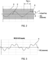
- FIG. 2 is a graph showing representative speed and vibration waveforms from the sensors shown in FIG. 1 .
- Shown in FIGS. 1 - 2 are engine sensor system 10, phonic wheel 12, teeth 14, index tooth 16, heavy spot 18, light spot 20, speed probe 22, accelerometer 24, speed signal 30, tooth zero crossing 32, and vibration signal 36.
- Also shown are angular rotational speed ⁇ , vibration phase ⁇ , and vibration amplitude A.
- Phonic wheel 12 rotates with a shaft (not shown) at angular rotational speed ⁇ .
- Non-limiting examples of a rotating shaft are a first spool shaft and a compressor core spool shaft.
- Phonic wheel 12 includes a number of teeth 14 that are spaced about the outer periphery. As phonic wheel 12 rotates, teeth 14 pass in the vicinity of speed probe 22 thereby inducing an electrical response corresponding to the rotation of phonic wheel 12. Phonic wheel 12 also includes index tooth 16 which can be used to identify the radial position of phonic wheel 12 relative to a datum (not shown).
- speed probe 22 is an inductive coil and teeth 14 are made of a ferromagnetic material that induces a voltage in speed probe 22 with the passing of each tooth 14, thereby producing a waveform of speed signal 30 as shown in FIG. 2 .
- Speed signal 30 is represented as a time-varying voltage over time.
- speed signal 30 is provided as an input to an EEC system (not shown in FIGS. 1 - 2 ).
- Phonic wheel 12 and speed sensor 22 depict an exemplary system for measuring the speed of a shaft, which can include a first spool shaft (i.e., the N1 speed), and a compressor core spool shaft (i.e., the N2 speed).
- engine sensor system 10 on a particular gas turbine engine can include two phonic wheels 12, each having an associated speed sensor 22. Accordingly, it is to be appreciated that two speed signals 30 will be used to represent the N1 speed and N2 speed, respectively, in a typical embodiment.
- a gas turbine engine can be prone to vibration during its operation (i.e., rotation of shafts), because even the most minute mass imbalances can result in rotational vibration at operating speeds.
- a mass imbalance in a particular shaft can be modeled as heavy spot 18 and light spot 20, as shown in FIG. 1 .
- the rotational vibration of a gas turbine engine can be detected by an accelerometer 24 that is included in engine sensor system 10.
- Accelerometer 24 produces vibration signal 36, which is represented as a time-varying electrical signal having vibrational amplitude A and vibrational phase ⁇ .
- vibration signal 36 is produced by a piezoelectric accelerometer and has units of electrical charge. Vibration signal 36 can be provided as an input to an EEC system.
- An EEC system can also be referred to as an EEC module.
- vibrational amplitude A and vibrational phase ⁇ can vary with the magnitude and radial positions of heavy spot 18 and/or light spot 20.
- a gas turbine engine includes a first spool shaft (i.e., N1 speed), and a compressor core spool shaft (i.e., N2 speed), as described above in regard to FIG. 1 , and that speed signal 30 represents a single speed signal (i.e., Nx speed signal).
- vibration signal 36 will contain vibration components of both the N1 and the N2 turbine speeds.
- FIG. 3 is a graph showing a representative N1 and N2 composite vibration waveform from accelerometer 24 shown in FIG. 1 . Shown in FIG. 3 is N1 and N2 composite vibration waveform 40, a time-varying electrical charge signal having frequency components of the N1 and N2 speeds. A gas turbine engine having two rotating shafts, each having a corresponding respective N1 and N2 speed, will be based on the rotational speeds of both shafts. Accordingly, accelerometer 24 detects vibration and produces an electrical output that is representative of the N1 and N2 speeds, as depicted by composite vibration waveform 40.
- FIG. 4A is a schematic block diagram showing an electronic engine control (EEC) signal simulator. Shown in FIG. 4A are signal simulator 50, first waveform generator 52, first data file 53, synchronizing signal output terminal 54, synchronizing signal 56, trigger signal output terminal 58, trigger signal 60, first waveform generator channel 1 output terminal 62, simulated N2 speed signal 64, first waveform generator channel 2 output terminal 66, vibration modulating signal 68, second waveform generator 70, second data file 71, synchronizing signal input terminal 72, trigger signal input terminal 74, modulation signal input terminal 76, second waveform generator channel 1 output terminal 78, simulated N1 speed signal 80, second waveform generator channel 2 output terminal 82, simulated composite vibration voltage signal 84, voltage to charge (V/C) converter 90, V/C converter input terminal 92, V/C converter output terminal 94, simulated composite vibration charge signal 96, electronic engine control (EEC) module 120, EEC module N2 speed input terminal 122, EEC module N1 speed input terminal 124, and EEC
- first waveform generator 52 is an arbitrary waveform generator that produces waveforms based on the reading of first data file 53.
- first data file 53 can be a comma-separated values (CSV) data file that programs waveform parameters.
- CSV comma-separated values
- AVG arbitrary waveform generator
- first data file 53 contains information representative of an N2 speed signal and the corresponding N2 vibration signal component.
- First waveform generator 52 produces synchronizing signal 56 at synchronizing signal output terminal 54 for use in synchronizing second waveform generator 70.
- synchronizing signal 56 is a 10 MHz signal.
- First waveform generator 52 also produces trigger signal 60 at trigger signal output terminal 58 for use in triggering second waveform generator 70.
- first waveform generator 52 Based on the data contained in first data file 53, first waveform generator 52 produces simulated N2 speed signal 64 at first waveform generator channel 1 output terminal 62, which can be provided as an input to EEC module 120.
- Simulated N2 speed signal 64 is a time-varying voltage signal that simulates the output of a speed probe (e.g., speed probe 22 as described above in regard to FIG. 1 ).
- First waveform generator 52 also produces vibration modulating signal 68 at first waveform generator channel 2 output terminal 66, which will be used by second waveform generator 70. Vibration modulating signal 68 is based on the N2 speed vibration component (i.e., representative of simulated N2 speed signal 64).
- second waveform generator 70 is an arbitrary waveform generator that produces waveforms based on the reading of second data file 71.
- second data file 71 can be a comma-separated values (CSV) data file that programs waveform parameters.
- second data file 71 contains information representative of an N1 speed signal and the corresponding N1 vibration signal component.
- Second waveform generator 70 receives synchronizing signal 56 at synchronizing signal input terminal 72, and trigger signal 60 at trigger signal input terminal 74, thereby synchronizing the operation of second waveform generator 70 to that of first waveform generator 52.
- second waveform generator 70 Based on the data contained in second data file 71, second waveform generator 70 produces simulated N1 speed signal 80 at second waveform generator channel 1 output terminal 78, which can be provided as an input to EEC module 120. Simulated N1 speed signal 80 is a time-varying voltage signal that simulates the output of a speed probe (e.g., speed probe 22, as described above in regard to FIG. 1 ). Second waveform generator 70 also produces simulated composite vibration voltage signal 84 at second waveform generator channel 2 output terminal 82, by modulating and/or summing the simulated N1 vibration signal component with the simulated N2 vibration signal component. Accordingly, simulated composite vibration voltage signal 84 contains vibration components of both the N1 and the N2 turbine speeds.
- Simulated N1 speed signal 80 is a time-varying voltage signal that simulates the output of a speed probe (e.g., speed probe 22, as described above in regard to FIG. 1 ). Second waveform generator 70 also produces simulated composite vibration voltage signal 84 at second waveform generator channel 2 output terminal
- Simulated composite vibration voltage signal 84 can also be referred to as a simulated first and second composite vibration voltage signal because it contains vibration components of both the N1 and the N2 speeds (i.e., the first and second speeds).
- simulated composite vibration voltage signal 84 is a time-varying voltage signal.
- an EEC system receives a time-varying electrical charge signal from accelerometer 24. Therefore, simulated composite vibration voltage signal 84 cannot be applied directly to EEC module 120.
- V/C converter 90 converts simulated composite vibration voltage signal 84 (i.e., a time-varying voltage signal) received at V/C converter input terminal 92 into simulated composite vibration charge signal 96 (i.e., a time-varying electrical charge signal) at V/C converter output terminal 94.
- signal simulator 50 simulates speed probe(s) 22 and vibration sensor 24 on a gas turbine engine (e.g., engine sensor system 10) for by providing simulated signals to EEC module 120.
- EEC module 120 receives simulated N2 speed signal 64 at EEC module N2 speed input terminal 122, simulated N1 speed signal 80 at EEC module N1 speed input terminal 124, and simulated composite vibration charge signal 96 at EEC module vibration signal input terminal 126.
- simulated N2 speed signal 64 can support a frequency range corresponding to a shaft rotational velocity from about 1 - 400 revolutions per second
- simulated N1 speed signal 80 can support a frequency range corresponding to a shaft rotational velocity from about 1 - 200 revolutions per second.
- Shaft rotational velocity can also be referred to as shaft rotational speed, or shaft speed.
- Shaft rotational velocity can be referred to as a "once per revolution” or "once per rev" frequency.
- a speed signal e.g., N2 speed, N1 speed
- a simulated shaft rotational velocity of 100 revolutions per second i.e., the once per rev frequency is 100 Hz
- simulated N2 speed signal 64 1,800 Hz.
- FIG. 4B is a schematic circuit diagram showing the detail of V/C converter 90. Shown in FIG. 4B are V/C converter 90, V/C converter input terminal 92, V/C converter output terminal 94, transformer 98, primary winding 100, secondary winding 102, capacitor 104, individual capacitors 106.
- V/C converter 90 includes transformer 98 having primary winding 100 and secondary winding 102. When a time-varying voltage is applied to primary winding 100, transformer 98 induces a time-varying voltage at secondary winding 102 by the mutual inductive coupling between primary winding 100 and secondary winding 102.
- transformer 98 is a transformer having a primary-to-secondary turns ratio of 1:1.
- transformer 98 can be a miniature or an ultra-miniature transformer. In other embodiments, transformer 98 can have a primary-to-secondary turns ratio between about 10:1 and 1:10. It is to be appreciated that in the transformer art, a turns ratio can be expressed as a ratio of the number of primary turns to the number of secondary terms, with each number in the ratio being at least 1.
- capacitor 104 has a capacitance of about 3,000 pF, with three individual capacitors 106 being connected in parallel to form capacitor 104.
- each individual capacitor 106 is a temperature-compensating ceramic capacitor having a rated capacitance value of 1,000 pF and a value tolerance of 1%.
- a temperature compensating ceramic capacitor can be referred to as a negative-positive 0 ppm/°C capacitor, or as an "NP0" or "NPO" ceramic capacitor.
- capacitor 104 can include any number of individual capacitors 106, either fewer than three or more than three. In some embodiments, capacitor 104 can be a single individual capacitor 106.
- the value of the capacitor 104 can be selected to match the specified nominal output capacitance of the accelerometer that is being simulated (e.g., accelerometer 24 as shown in FIG. 1 ). Accordingly, in some embodiments, capacitor 104 can have a capacitance value that ranges between about 1,000 and 20,000 pF to match the output capacitance of a particular accelerometer. In other embodiments, capacitor 104 can have a capacitance value that is less than 1,000 pF, or more than 20,000 pF. In yet other embodiments, the value tolerance on capacitor 104 and/or individual capacitors 106 can be less than 1% or more than 1%. In some embodiments, capacitor 104 and/or individual capacitors 106 can be capacitors having a type other than a temperature-compensating ceramic capacitor.
- a system for generating input signals for an electronic engine control (EEC) module comprising: a first waveform generator that is configured to generate: a simulated first speed signal that is representative of a first speed; and a vibration modulating signal that is representative of the first speed; a second waveform generator, synchronized with the first waveform generator, that is configured to receive the vibration modulating signal and to generate: a simulated second speed signal that is representative of a second speed; and a simulated composite vibration voltage signal; and a voltage-to-charge (V/Q) converter that is configured to receive the simulated composite vibration voltage signal from the second waveform generator and to generate a simulated composite vibration charge signal that simulates a speed/vibration composite signal from an accelerometer.
- EEC electronic engine control
- the system of the preceding paragraph can optionally include, additionally and/or alternatively, any one or more of the following features, configurations and/or additional components:
- the first waveform generator comprises a first arbitrary waveform generator that is configured to: read a first data file that is representative of a modeled first speed; generate the simulated first speed signal in response to the first data file; and generate the vibration modulating signal in response to the first data file; and the second waveform generator comprises a second arbitrary waveform generator that is configured to: read a second data file that is representative of a modeled second speed; generate the simulated second signal in response to the second data file; and generate the simulated composite vibration voltage signal in response to the second data file and the vibration modulating signal.
- the V/Q converter comprises: a transformer, including a primary winding and a secondary winding; and a capacitor, defining a capacitor input terminal and a capacitor output terminal; wherein: the transformer is configured to: receive the simulated composite vibration voltage signal at the primary winding; produce, by inductive coupling, an induced first and second composite vibration voltage signal at the secondary winding; and apply the induced first and second composite vibration voltage signal to the capacitor input terminal; and the capacitor is configured to: receive, at the capacitor input terminal, the induced first and second composite vibration voltage signal; and produce, by electrostatic coupling, the simulated composite vibration charge signal at the capacitor output terminal.
- the first waveform generator if further configured to: produce a synchronizing signal and a trigger signal; and input the synchronizing signal and the trigger signal to the second waveform generator, thereby synchronizing the second waveform generator with the first waveform generator.
- a further embodiment of the foregoing system wherein the first speed is representative of an N2 speed; and the second speed is representative of an N1 speed.
- transformer has a primary-to-secondary turns ratio between 1:10 and 10:1.
- transformer has a primary-to-secondary turns ratio of about 1:1.
- transformer is miniature or an ultra-miniature transformer.
- the capacitor comprises three parallel-connected temperature-compensating ceramic capacitors, each having a capacitance of about 1,000 pF.
- first data file is a first comma-separated values (CSV) data file
- second data file is a second CSV file
- synchronizing signal is a 10 MHz synchronizing clock signal.
- simulated N2 speed signal corresponds to a shaft rotational speed between 1 - 400 revolutions per second.
- simulated N1 speed signal corresponds to a shaft rotational speed between 1 - 200 revolutions per second.
- a further embodiment of the foregoing system further comprising an EEC module for a gas turbine engine, configured to receive the simulated first speed signal, the simulated second speed signal, and the simulated composite vibration charge signal.
- a method of generating input signals for an electronic engine control (EEC) module by using a first and second waveform generator and a voltage-to-charge (V/Q) converter comprising: generating, by the first waveform generator: a simulated first speed signal that is representative of a first speed; and a vibration modulating signal that is representative of the first speed; inputting, from the first waveform generator to the second waveform generator, the vibration modulating signal; generating, by the second waveform generator: a simulated second signal that is representative of a second speed; and a simulated composite vibration voltage signal that is representative of the second speed and the vibration modulating signal; wherein the second waveform generator is synchronized with the first waveform generator; and generating, by the V/Q converter, a simulated composite vibration charge signal that simulates a speed/vibration composite signal from an accelerometer, wherein the simulated composite vibration charge signal is representative of the simulated composite vibration voltage signal.
- EEC electronic engine control
- V/Q voltage-to-charge
- the method of the preceding paragraph can optionally include, additionally and/or alternatively, any one or more of the following features, configurations and/or additional components:
- the first waveform generator comprises a first arbitrary waveform generator that is configured to: read a first data file that is representative of a modeled first speed; generate the simulated first speed signal in response to the first data file; and generate the vibration modulating signal in response to the first data file; and the second waveform generator comprises a second arbitrary waveform generator that is configured to: read a second data file that is representative of a modeled second speed; generate the simulated second signal in response to the second data file; and generate the simulated composite vibration voltage signal in response to the second data file and the vibration modulating signal.
- the V/Q converter comprises: a transformer, including a primary winding and a secondary winding; and a capacitor, defining a capacitor input terminal and a capacitor output terminal; wherein: the transformer is configured to: receive the simulated composite vibration voltage signal at the primary winding; produce, by inductive coupling, an induced first and second composite vibration voltage signal at the secondary winding; and apply the induced first and second composite vibration voltage signal to the capacitor input terminal; and the capacitor is configured to: receive, at the capacitor input terminal, the induced first and second composite vibration voltage signal; and produce, by electrostatic coupling, the simulated composite vibration charge signal at the capacitor output terminal.
- the second waveform generator is synchronized with the first waveform generator by a method comprising: generating, by the first waveform generator, a synchronizing signal and a trigger signal; and inputting, from the first waveform generator to the second waveform generator, the synchronizing signal and the trigger signal.
- a further embodiment of the foregoing method wherein: the first speed is representative of an N2 speed; and the second speed is representative of an N1 speed.
Landscapes
- Engineering & Computer Science (AREA)
- Chemical & Material Sciences (AREA)
- Combustion & Propulsion (AREA)
- Physics & Mathematics (AREA)
- General Physics & Mathematics (AREA)
- Automation & Control Theory (AREA)
- Aviation & Aerospace Engineering (AREA)
- General Engineering & Computer Science (AREA)
- Mechanical Engineering (AREA)
- Manufacturing & Machinery (AREA)
- Human Computer Interaction (AREA)
- Electromagnetism (AREA)
- Radar, Positioning & Navigation (AREA)
- Health & Medical Sciences (AREA)
- Artificial Intelligence (AREA)
- Computer Vision & Pattern Recognition (AREA)
- Evolutionary Computation (AREA)
- Medical Informatics (AREA)
- Software Systems (AREA)
- Testing Of Devices, Machine Parts, Or Other Structures Thereof (AREA)
Description
- Modem aircraft engines and associated systems operate at increasingly higher performance and efficiencies, placing greater demands on electronic engine control (EEC) systems. Accordingly, the developing and/or testing of modern EEC systems is important to help optimize this performance, but a gas turbine engine is typically required to generate the various speed and vibration signals for system development and verification testing, which can be wasteful of resources. There is a need for simulating the speed and vibration signals from the detectors on a gas turbine engine for use in efficiently developing and/or testing these modern EEC systems.
EP 2 674 741 - A system for generating input signals for an electronic engine control module is provided in
claim 1 and includes a first waveform generator that is configured to generate a simulated first speed signal that is representative of a first speed and a vibration modulating signal that is representative of the first speed, a second waveform generator that is synchronized with the first waveform generator and is configured to generate a simulated second speed signal that is representative of a second speed and a vibration modulating signal that is representative of the second speed and a simulated composite vibration voltage signal comprised of the vibration modulating signal that is representative of the first speed received from the first waveform generator and the vibration modulating signal that is representative of the second speed, and a voltage-to-charge converter that is configured to receive the simulated composite vibration voltage signal from the second waveform generator and to generate a simulated composite vibration charge signal that simulates a vibration composite signal from an accelerometer based on the first and second speeds. - A method of generating input signals for an electronic engine control module by using a first and second waveform generator and a voltage-to-charge converter is provided in
claim 10 and includes: generating, by the first waveform generator, a simulated first speed signal that is representative of a first speed and a vibration modulating signal that is representative of the first speed; inputting, from the first waveform generator to the second waveform generator that is synchronized with the first waveform generator, the vibration modulating signal; generating, by the second waveform generator, a simulated second signal that is representative of a second speed and a simulated composite vibration voltage signal that is representative of the second speed and the vibration modulating signal; and generating, by the voltage-to-charge converter, a simulated composite vibration charge signal that simulates a vibration composite signal from an accelerometer based on the first and second speeds. The simulated composite vibration charge signal is representative of the simulated composite vibration voltage signal. -
-
FIG. 1 is a schematic diagram showing a phonic wheel and associated sensors on an engine shaft. -
FIG. 2 is a graph showing representative speed and vibration waveforms from the sensors shown inFIG. 1 . -
FIG. 3 is a graph showing a representative N1 and N2 composite vibration waveform from a sensor shown inFIG. 1 -
FIG. 4A is a schematic block diagram showing an electronic engine control (EEC) vibration test simulator. -
FIG. 4B is a schematic circuit diagram showing the detail of a voltage-to-charge (V/C) converter. - Modem electronic engine control (EEC) systems, such as those used on gas turbine engines, help improve the performance and/or efficiency of gas turbine engines under various loads and during various phases of operation. EEC systems monitor and respond to various parameters that are sensed by various sensors. For example, the first spool speed (or fan speed) can be represented as an N1 speed, and the core compressor spool speed can be represented as an N2 speed. Independent speed probes can be used to sense the N1 and N2 speeds. An electromagnetic sensor that detects the passing of teeth on a phonic wheel on a shaft is an example of a speed probe. The N1 and N2 speeds are each represented as a voltage signal having the form of a cyclical (i.e., time-varying) waveform that are input to the EEC system. In addition to the speed probes, an accelerometer can used to detect the vibration of a gas turbine engine. An accelerometer can use a piezoelectric crystal to produce a cyclical (i.e., time-varying) waveform that represents an electrical charge as a function of acceleration, with this signal also being input to the EEC system. The vibration signal from an accelerometer is typically a composite signal that is related to the rotational speeds of the various shafts within the gas turbine engine, which is related to the N1 and N2 speed signals described above. Accordingly, the vibration signal can be representative of an N1/N2 composite sum signal.
- Despite the precision with which modern gas turbine engines are manufactured, some amount of vibration exists during their operation as a result of the rotations of the various shafts and associated components. It can be important to monitor vibration so that the EEC system can control the gas turbine engine to reduce the vibration during operation of the gas turbine engine as well as support on-condition maintenance actions. This can be beneficial for prolonging the life of the gas turbine engine and/or reducing maintenance requirements, while also reducing the fatigue on engine support components. Moreover, controlling the operating performance of a gas turbine engine can result in less noise that is radiated into the aircraft and/or the surrounding environment. Accordingly, it can be important to optimize the performance of EEC systems, which can include electronic hardware systems and embedded software. In developing and/or testing an EEC system, a gas turbine engine can be operated to produce the N1 and N2 speed signals and the composite vibration signal. This requires using an operational gas turbine engine which requires burning fuel, and the associated time, cost, and maintenance requirements.
- The present disclosure is directed to a system and method for simulating N1 and N2 speed signals and an N1/N2 vibration composite signal that can be provided as inputs to an EEC system for use in developing and testing an EEC system, which can include the model-based testing of EEC electronic hardware and/or embedded software.
-
FIG. 1 is a schematic diagram showing a phonic wheel and sensors used to detect speed and vibration of a shaft on a gas turbine engine.FIG. 2 is a graph showing representative speed and vibration waveforms from the sensors shown inFIG. 1 . Shown inFIGS. 1 - 2 areengine sensor system 10,phonic wheel 12,teeth 14,index tooth 16,heavy spot 18,light spot 20,speed probe 22,accelerometer 24,speed signal 30, tooth zerocrossing 32, andvibration signal 36. Also shown are angular rotational speed ω, vibration phase ϕ, and vibration amplitude A.Phonic wheel 12 rotates with a shaft (not shown) at angular rotational speed ω. Non-limiting examples of a rotating shaft are a first spool shaft and a compressor core spool shaft.Phonic wheel 12 includes a number ofteeth 14 that are spaced about the outer periphery. Asphonic wheel 12 rotates,teeth 14 pass in the vicinity ofspeed probe 22 thereby inducing an electrical response corresponding to the rotation ofphonic wheel 12.Phonic wheel 12 also includesindex tooth 16 which can be used to identify the radial position ofphonic wheel 12 relative to a datum (not shown). In the illustrated embodiment,speed probe 22 is an inductive coil andteeth 14 are made of a ferromagnetic material that induces a voltage inspeed probe 22 with the passing of eachtooth 14, thereby producing a waveform ofspeed signal 30 as shown inFIG. 2 .Speed signal 30 is represented as a time-varying voltage over time. Eachtooth 14passes speed probe 22, thereby creating a tooth zero crossing 32 as shown. In a typical embodiment,speed signal 30 is provided as an input to an EEC system (not shown inFIGS. 1 - 2 ).Phonic wheel 12 andspeed sensor 22 depict an exemplary system for measuring the speed of a shaft, which can include a first spool shaft (i.e., the N1 speed), and a compressor core spool shaft (i.e., the N2 speed). Accordingly, in an exemplary embodiment,engine sensor system 10 on a particular gas turbine engine (not shown) can include twophonic wheels 12, each having an associatedspeed sensor 22. Accordingly, it is to be appreciated that twospeed signals 30 will be used to represent the N1 speed and N2 speed, respectively, in a typical embodiment. - As described above, a gas turbine engine can be prone to vibration during its operation (i.e., rotation of shafts), because even the most minute mass imbalances can result in rotational vibration at operating speeds. A mass imbalance in a particular shaft can be modeled as
heavy spot 18 andlight spot 20, as shown inFIG. 1 . The rotational vibration of a gas turbine engine can be detected by anaccelerometer 24 that is included inengine sensor system 10. Accelerometer 24 producesvibration signal 36, which is represented as a time-varying electrical signal having vibrational amplitude A and vibrational phase ϕ. In the illustrated embodiment,vibration signal 36 is produced by a piezoelectric accelerometer and has units of electrical charge.Vibration signal 36 can be provided as an input to an EEC system. An EEC system can also be referred to as an EEC module. It is to be appreciated that vibrational amplitude A and vibrational phase ϕ can vary with the magnitude and radial positions ofheavy spot 18 and/orlight spot 20. It is also to be appreciated that a gas turbine engine includes a first spool shaft (i.e., N1 speed), and a compressor core spool shaft (i.e., N2 speed), as described above in regard toFIG. 1 , and thatspeed signal 30 represents a single speed signal (i.e., Nx speed signal). Accordingly, in some embodiments,vibration signal 36 will contain vibration components of both the N1 and the N2 turbine speeds. -
FIG. 3 is a graph showing a representative N1 and N2 composite vibration waveform fromaccelerometer 24 shown inFIG. 1 . Shown inFIG. 3 is N1 and N2composite vibration waveform 40, a time-varying electrical charge signal having frequency components of the N1 and N2 speeds. A gas turbine engine having two rotating shafts, each having a corresponding respective N1 and N2 speed, will be based on the rotational speeds of both shafts. Accordingly,accelerometer 24 detects vibration and produces an electrical output that is representative of the N1 and N2 speeds, as depicted bycomposite vibration waveform 40. -
FIG. 4A is a schematic block diagram showing an electronic engine control (EEC) signal simulator. Shown inFIG. 4A aresignal simulator 50,first waveform generator 52,first data file 53, synchronizingsignal output terminal 54, synchronizingsignal 56, triggersignal output terminal 58,trigger signal 60, firstwaveform generator channel 1output terminal 62, simulatedN2 speed signal 64, firstwaveform generator channel 2output terminal 66,vibration modulating signal 68,second waveform generator 70, second data file 71, synchronizingsignal input terminal 72, triggersignal input terminal 74, modulationsignal input terminal 76, secondwaveform generator channel 1output terminal 78, simulatedN1 speed signal 80, secondwaveform generator channel 2output terminal 82, simulated compositevibration voltage signal 84, voltage to charge (V/C)converter 90, V/Cconverter input terminal 92, V/Cconverter output terminal 94, simulated compositevibration charge signal 96, electronic engine control (EEC)module 120, EEC module N2speed input terminal 122, EEC module N1speed input terminal 124, and EEC module vibrationsignal input terminal 126. In the illustrated embodiment,first waveform generator 52 is an arbitrary waveform generator that produces waveforms based on the reading offirst data file 53. In a particular embodiment, first data file 53 can be a comma-separated values (CSV) data file that programs waveform parameters. It is to be appreciated that in the electrical art, an "arbitrary waveform generator" (AWG) is a piece of electronic test equipment that can be used to synthesize a waveform by inputting various parameters that describe the desired waveform. In the illustrated embodiment, first data file 53 contains information representative of an N2 speed signal and the corresponding N2 vibration signal component.First waveform generator 52 produces synchronizingsignal 56 at synchronizingsignal output terminal 54 for use in synchronizingsecond waveform generator 70. In the illustrated embodiment, synchronizingsignal 56 is a 10 MHz signal.First waveform generator 52 also producestrigger signal 60 at triggersignal output terminal 58 for use in triggeringsecond waveform generator 70. Based on the data contained infirst data file 53,first waveform generator 52 produces simulatedN2 speed signal 64 at firstwaveform generator channel 1output terminal 62, which can be provided as an input toEEC module 120. SimulatedN2 speed signal 64 is a time-varying voltage signal that simulates the output of a speed probe (e.g.,speed probe 22 as described above in regard toFIG. 1 ).First waveform generator 52 also producesvibration modulating signal 68 at firstwaveform generator channel 2output terminal 66, which will be used bysecond waveform generator 70.Vibration modulating signal 68 is based on the N2 speed vibration component (i.e., representative of simulated N2 speed signal 64). - In the illustrated embodiment,
second waveform generator 70 is an arbitrary waveform generator that produces waveforms based on the reading of second data file 71. In a particular embodiment, second data file 71 can be a comma-separated values (CSV) data file that programs waveform parameters. In the illustrated embodiment, second data file 71 contains information representative of an N1 speed signal and the corresponding N1 vibration signal component.Second waveform generator 70 receives synchronizingsignal 56 at synchronizingsignal input terminal 72, and triggersignal 60 at triggersignal input terminal 74, thereby synchronizing the operation ofsecond waveform generator 70 to that offirst waveform generator 52. Based on the data contained in second data file 71,second waveform generator 70 produces simulatedN1 speed signal 80 at secondwaveform generator channel 1output terminal 78, which can be provided as an input toEEC module 120. SimulatedN1 speed signal 80 is a time-varying voltage signal that simulates the output of a speed probe (e.g.,speed probe 22, as described above in regard toFIG. 1 ).Second waveform generator 70 also produces simulated compositevibration voltage signal 84 at secondwaveform generator channel 2output terminal 82, by modulating and/or summing the simulated N1 vibration signal component with the simulated N2 vibration signal component. Accordingly, simulated compositevibration voltage signal 84 contains vibration components of both the N1 and the N2 turbine speeds. Simulated compositevibration voltage signal 84 can also be referred to as a simulated first and second composite vibration voltage signal because it contains vibration components of both the N1 and the N2 speeds (i.e., the first and second speeds). In the illustrated embodiment, simulated compositevibration voltage signal 84 is a time-varying voltage signal. As described above in regard toFIGS. 1 - 2 , an EEC system receives a time-varying electrical charge signal fromaccelerometer 24. Therefore, simulated compositevibration voltage signal 84 cannot be applied directly toEEC module 120. In the illustrated embodiment, V/C converter 90 converts simulated composite vibration voltage signal 84 (i.e., a time-varying voltage signal) received at V/Cconverter input terminal 92 into simulated composite vibration charge signal 96 (i.e., a time-varying electrical charge signal) at V/Cconverter output terminal 94. Accordingly,signal simulator 50 simulates speed probe(s) 22 andvibration sensor 24 on a gas turbine engine (e.g., engine sensor system 10) for by providing simulated signals toEEC module 120.EEC module 120 receives simulatedN2 speed signal 64 at EEC module N2speed input terminal 122, simulatedN1 speed signal 80 at EEC module N1speed input terminal 124, and simulated compositevibration charge signal 96 at EEC module vibrationsignal input terminal 126. In the illustrated embodiment, simulatedN2 speed signal 64 can support a frequency range corresponding to a shaft rotational velocity from about 1 - 400 revolutions per second, and simulatedN1 speed signal 80 can support a frequency range corresponding to a shaft rotational velocity from about 1 - 200 revolutions per second. Shaft rotational velocity can also be referred to as shaft rotational speed, or shaft speed. Shaft rotational velocity can be referred to as a "once per revolution" or "once per rev" frequency. It is to be appreciated that in a particular embodiment, a speed signal (e.g., N2 speed, N1 speed) are typically a product of the shaft rotational velocity and the number of teeth on the associated phonic wheel. For example, in simulating an N2 speed signal for an embodiment where the associated phonic wheel has eighteen teeth (e.g., as shown inFIG. 1 ), a simulated shaft rotational velocity of 100 revolutions per second (i.e., the once per rev frequency is 100 Hz) would result in simulatedN2 speed signal 64 being 1,800 Hz. -
FIG. 4B is a schematic circuit diagram showing the detail of V/C converter 90. Shown inFIG. 4B are V/C converter 90, V/Cconverter input terminal 92, V/Cconverter output terminal 94,transformer 98, primary winding 100, secondary winding 102,capacitor 104,individual capacitors 106. V/C converter 90 includestransformer 98 having primary winding 100 and secondary winding 102. When a time-varying voltage is applied to primary winding 100,transformer 98 induces a time-varying voltage at secondary winding 102 by the mutual inductive coupling between primary winding 100 and secondary winding 102. In the illustrated embodiment,transformer 98 is a transformer having a primary-to-secondary turns ratio of 1:1. In some embodiments,transformer 98 can be a miniature or an ultra-miniature transformer. In other embodiments,transformer 98 can have a primary-to-secondary turns ratio between about 10:1 and 1:10. It is to be appreciated that in the transformer art, a turns ratio can be expressed as a ratio of the number of primary turns to the number of secondary terms, with each number in the ratio being at least 1. - Referring again to
FIG. 4B , secondary winding 102 is series-connected to capacitor 104 with respect to ground. In the illustrated embodiment,capacitor 104 has a capacitance of about 3,000 pF, with threeindividual capacitors 106 being connected in parallel to formcapacitor 104. In the illustrated embodiment, eachindividual capacitor 106 is a temperature-compensating ceramic capacitor having a rated capacitance value of 1,000 pF and a value tolerance of 1%. A temperature compensating ceramic capacitor can be referred to as a negative-positive 0 ppm/°C capacitor, or as an "NP0" or "NPO" ceramic capacitor. In some embodiments,capacitor 104 can include any number ofindividual capacitors 106, either fewer than three or more than three. In some embodiments,capacitor 104 can be a singleindividual capacitor 106. - In a particular embodiment, the value of the
capacitor 104 can be selected to match the specified nominal output capacitance of the accelerometer that is being simulated (e.g.,accelerometer 24 as shown inFIG. 1 ). Accordingly, in some embodiments,capacitor 104 can have a capacitance value that ranges between about 1,000 and 20,000 pF to match the output capacitance of a particular accelerometer. In other embodiments,capacitor 104 can have a capacitance value that is less than 1,000 pF, or more than 20,000 pF. In yet other embodiments, the value tolerance oncapacitor 104 and/orindividual capacitors 106 can be less than 1% or more than 1%. In some embodiments,capacitor 104 and/orindividual capacitors 106 can be capacitors having a type other than a temperature-compensating ceramic capacitor. - A system for generating input signals for an electronic engine control (EEC) module, the system comprising: a first waveform generator that is configured to generate: a simulated first speed signal that is representative of a first speed; and a vibration modulating signal that is representative of the first speed; a second waveform generator, synchronized with the first waveform generator, that is configured to receive the vibration modulating signal and to generate: a simulated second speed signal that is representative of a second speed; and a simulated composite vibration voltage signal; and a voltage-to-charge (V/Q) converter that is configured to receive the simulated composite vibration voltage signal from the second waveform generator and to generate a simulated composite vibration charge signal that simulates a speed/vibration composite signal from an accelerometer.
- The system of the preceding paragraph can optionally include, additionally and/or alternatively, any one or more of the following features, configurations and/or additional components:
- A further embodiment of the foregoing system, wherein the first waveform generator comprises a first arbitrary waveform generator that is configured to: read a first data file that is representative of a modeled first speed; generate the simulated first speed signal in response to the first data file; and generate the vibration modulating signal in response to the first data file; and the second waveform generator comprises a second arbitrary waveform generator that is configured to: read a second data file that is representative of a modeled second speed; generate the simulated second signal in response to the second data file; and generate the simulated composite vibration voltage signal in response to the second data file and the vibration modulating signal.
- A further embodiment of the foregoing system, wherein the V/Q converter comprises: a transformer, including a primary winding and a secondary winding; and a capacitor, defining a capacitor input terminal and a capacitor output terminal; wherein: the transformer is configured to: receive the simulated composite vibration voltage signal at the primary winding; produce, by inductive coupling, an induced first and second composite vibration voltage signal at the secondary winding; and apply the induced first and second composite vibration voltage signal to the capacitor input terminal; and the capacitor is configured to: receive, at the capacitor input terminal, the induced first and second composite vibration voltage signal; and produce, by electrostatic coupling, the simulated composite vibration charge signal at the capacitor output terminal.
- A further embodiment of the foregoing system, wherein the first waveform generator if further configured to: produce a synchronizing signal and a trigger signal; and input the synchronizing signal and the trigger signal to the second waveform generator, thereby synchronizing the second waveform generator with the first waveform generator.
- A further embodiment of the foregoing system, wherein the first speed is representative of an N2 speed; and the second speed is representative of an N1 speed.
- A further embodiment of the foregoing system, wherein the transformer has a primary-to-secondary turns ratio between 1:10 and 10:1.
- A further embodiment of the foregoing system, wherein the transformer has a primary-to-secondary turns ratio of about 1:1.
- A further embodiment of the foregoing system, wherein the transformer is miniature or an ultra-miniature transformer.
- A further embodiment of the foregoing system, wherein the capacitor has a capacitance between 1,000 and 20,000 pF.
- A further embodiment of the foregoing system, wherein the capacitor comprises three parallel-connected temperature-compensating ceramic capacitors, each having a capacitance of about 1,000 pF.
- A further embodiment of the foregoing system, wherein the first data file is a first comma-separated values (CSV) data file; and the second data file is a second CSV file.
- A further embodiment of the foregoing system, wherein the synchronizing signal is a 10 MHz synchronizing clock signal.
- A further embodiment of the foregoing system, wherein the simulated N2 speed signal corresponds to a shaft rotational speed between 1 - 400 revolutions per second.
- A further embodiment of the foregoing system, wherein the simulated N1 speed signal corresponds to a shaft rotational speed between 1 - 200 revolutions per second.
- A further embodiment of the foregoing system, further comprising an EEC module for a gas turbine engine, configured to receive the simulated first speed signal, the simulated second speed signal, and the simulated composite vibration charge signal.
- A method of generating input signals for an electronic engine control (EEC) module by using a first and second waveform generator and a voltage-to-charge (V/Q) converter, the method comprising: generating, by the first waveform generator: a simulated first speed signal that is representative of a first speed; and a vibration modulating signal that is representative of the first speed; inputting, from the first waveform generator to the second waveform generator, the vibration modulating signal; generating, by the second waveform generator: a simulated second signal that is representative of a second speed; and a simulated composite vibration voltage signal that is representative of the second speed and the vibration modulating signal; wherein the second waveform generator is synchronized with the first waveform generator; and generating, by the V/Q converter, a simulated composite vibration charge signal that simulates a speed/vibration composite signal from an accelerometer, wherein the simulated composite vibration charge signal is representative of the simulated composite vibration voltage signal.
- The method of the preceding paragraph can optionally include, additionally and/or alternatively, any one or more of the following features, configurations and/or additional components:
- A further embodiment of the foregoing method, wherein: the first waveform generator comprises a first arbitrary waveform generator that is configured to: read a first data file that is representative of a modeled first speed; generate the simulated first speed signal in response to the first data file; and generate the vibration modulating signal in response to the first data file; and the second waveform generator comprises a second arbitrary waveform generator that is configured to: read a second data file that is representative of a modeled second speed; generate the simulated second signal in response to the second data file; and generate the simulated composite vibration voltage signal in response to the second data file and the vibration modulating signal.
- A further embodiment of the foregoing method, wherein the V/Q converter comprises: a transformer, including a primary winding and a secondary winding; and a capacitor, defining a capacitor input terminal and a capacitor output terminal; wherein: the transformer is configured to: receive the simulated composite vibration voltage signal at the primary winding; produce, by inductive coupling, an induced first and second composite vibration voltage signal at the secondary winding; and apply the induced first and second composite vibration voltage signal to the capacitor input terminal; and the capacitor is configured to: receive, at the capacitor input terminal, the induced first and second composite vibration voltage signal; and produce, by electrostatic coupling, the simulated composite vibration charge signal at the capacitor output terminal.
- A further embodiment of the foregoing method, wherein the second waveform generator is synchronized with the first waveform generator by a method comprising: generating, by the first waveform generator, a synchronizing signal and a trigger signal; and inputting, from the first waveform generator to the second waveform generator, the synchronizing signal and the trigger signal.
- A further embodiment of the foregoing method, wherein: the first speed is representative of an N2 speed; and the second speed is representative of an N1 speed.
- While the invention has been described with reference to an exemplary embodiment(s), it will be understood by those skilled in the art that various changes may be made without departing from the scope of the invention as defined in the appended claims. Therefore, it is intended that the invention not be limited to the particular embodiment(s) disclosed, but that the invention will include all embodiments falling within the scope of the appended claims.
Claims (13)
- A system for generating simulated input signals for an electronic engine control, EEC, module, the system comprising:a first waveform generator (52) that is configured to generate:a simulated first speed signal that is representative of a first speed; anda vibration modulating signal that is representative of the first speed;wherein the first waveform generator (52) provides the simulated first speed signal as input to the EEC module at a first output terminal;a second waveform generator (70), synchronized with the first waveform generator, that is configured to receive the vibration modulating signal and to generate:a simulated second speed signal that is representative of a second speed; anda simulated composite vibration voltage signal;wherein the second waveform generator (70) configured to provide the simulated second waveform signal as input to the EEC module at a second output terminal;a voltage-to-charge, V/Q, converter (90) that is configured to receive the simulated composite vibration voltage signal from the second waveform generator and to generate a simulated composite vibration charge signal that simulates a speed/vibration composite signal from an accelerometer;wherein the V/Q converter configured to transmit the simulated composite vibration charge signal as input to the EEC module at a third output terminal,wherein the V/Q converter comprises:a transformer (98), including a primary winding (100) and a secondary winding (102); anda capacitor (104), defining a capacitor input terminal and a capacitor output terminal;wherein:the transformer (98) is configured to:receive the simulated composite vibration voltage signal at the primary winding;produce, by inductive coupling, an induced first and second composite vibration voltage signal at the secondary winding; andapply the induced first and second composite vibration voltage signal to the capacitor input terminal; andthe capacitor is configured to:receive, at the capacitor input terminal, the induced first and second composite vibration voltage signal; andproduce, by electrostatic coupling, the simulated composite vibration charge signal at the capacitor output terminal.
- The system of claim 1, wherein:the first waveform generator (52) comprises a first arbitrary waveform generator that is configured to:read a first data file that is representative of a modeled first speed;generate the simulated first speed signal in response to the first data file; andgenerate the vibration modulating signal in response to the first data file; andthe second waveform generator (70) comprises a second arbitrary waveform generator that is configured to:read a second data file that is representative of a modeled second speed;generate the simulated second signal in response to the second data file; andgenerate the simulated composite vibration voltage signal in response to the second data file and the vibration modulating signal.
- The system of any preceding claim, wherein the first waveform generator (52) if further configured to:
produce a synchronizing signal and a trigger signal; and
input the synchronizing signal and the trigger signal to the second waveform generator, thereby synchronizing the second waveform generator with the first waveform generator. - The system of any preceding claim, wherein:the first speed is representative of an N2 speed; andthe second speed is representative of an N1 speed.
- The system of any preceding claim, wherein the transformer (98) has a primary-to-secondary turns ratio between 1:10 and 10:1, wherein the transformer is miniature or an ultra-miniature transformer.
- The system of any preceding claim, wherein the capacitor has a capacitance between 1,000 and 20,000 pF, and wherein the capacitor comprises three parallel-connected temperature-compensating ceramic capacitors.
- The system of claim 2, wherein:the first data file is a first comma-separated values, CSV, data file; andthe second data file is a second CSV file.
- The system of claim 4, wherein the simulated N2 speed signal corresponds to a shaft rotational speed between 1 - 400 revolutions per second; and/or wherein the simulated N1 speed signal corresponds to a shaft rotational speed between 1 - 200 revolutions per second.
- The system of claim 1, further comprising:
the EEC module for a gas turbine engine, wherein the EEC module is configured to receive the simulated first speed signal, the simulated second speed signal, and the simulated composite vibration charge signal. - A method of generating input signals for an electronic engine control, EEC, module by using a first and second waveform generator and a voltage-to-charge, V/Q, converter, the method comprising:generating, by the first waveform generator:a simulated first speed signal that is representative of a first speed; anda vibration modulating signal that is representative of the first speed;providing by the first waveform generator, the simulated first speed signal as input to the EEC module at a first output terminal;inputting, from the first waveform generator to the second waveform generator, the vibration modulating signal;generating, by the second waveform generator:a simulated second signal that is representative of a second speed; anda simulated composite vibration voltage signal that is representative of the second speed and the vibration modulating signal;wherein the second waveform generator is synchronized with the first waveform generator;providing by the second waveform generator, the simulated second signal as input to the EEC module at a second output terminal;generating, by the V/Q converter, a simulated composite vibration charge signal that simulates a speed/vibration composite signal from an accelerometer, wherein the simulated composite vibration charge signal is representative of the simulated composite vibration voltage signal; andproviding, by the V/Q converter, the simulated composite vibration charge signal as input to the EEC module at a third output terminal,wherein the V/Q converter comprises:a transformer, including a primary winding and a secondary winding; anda capacitor, defining a capacitor input terminal and a capacitor output terminal;wherein:the transformer is configured to:receive the simulated composite vibration voltage signal at the primary winding;produce, by inductive coupling, an induced first and second composite vibration voltage signal at the secondary winding; andapply the induced first and second composite vibration voltage signal to the capacitor input terminal; andthe capacitor is configured to:receive, at the capacitor input terminal, the induced first and second composite vibration voltage signal; andproduce, by electrostatic coupling, the simulated composite vibration charge signal at the capacitor output terminal.
- The method of claim 10, wherein:the first waveform generator comprises a first arbitrary waveform generator that is configured to:read a first data file that is representative of a modeled first speed;generate the simulated first speed signal in response to the first data file; andgenerate the vibration modulating signal in response to the first data file; andthe second waveform generator comprises a second arbitrary waveform generator that is configured to:read a second data file that is representative of a modeled second speed;generate the simulated second signal in response to the second data file; andgenerate the simulated composite vibration voltage signal in response to the second data file and the vibration modulating signal.
- The method of any of claims 10-11, wherein the second waveform generator is synchronized with the first waveform generator by a method comprising:generating, by the first waveform generator, a synchronizing signal and a trigger signal; andinputting, from the first waveform generator to the second waveform generator, the synchronizing signal and the trigger signal.
- The method of any of claims 10-12, wherein:the first speed is representative of an N2 speed; andthe second speed is representative of an N1 speed.
Applications Claiming Priority (1)
| Application Number | Priority Date | Filing Date | Title |
|---|---|---|---|
| US16/362,075 US11474494B2 (en) | 2019-03-22 | 2019-03-22 | Method for simulating an N1 and N2 speed vibration composite input for development and/or model based testing of engine control hardware and embedded software |
Publications (2)
| Publication Number | Publication Date |
|---|---|
| EP3712413A1 EP3712413A1 (en) | 2020-09-23 |
| EP3712413B1 true EP3712413B1 (en) | 2023-08-23 |
Family
ID=68731815
Family Applications (1)
| Application Number | Title | Priority Date | Filing Date |
|---|---|---|---|
| EP19212093.9A Active EP3712413B1 (en) | 2019-03-22 | 2019-11-28 | Method for simulating an n1 and n2 speed vibration composite input for development and/or model based testing of engine control hardware and embedded software |
Country Status (2)
| Country | Link |
|---|---|
| US (1) | US11474494B2 (en) |
| EP (1) | EP3712413B1 (en) |
Families Citing this family (3)
| Publication number | Priority date | Publication date | Assignee | Title |
|---|---|---|---|---|
| US11203420B2 (en) * | 2019-05-03 | 2021-12-21 | Pratt & Whitney Canada Corp. | System and method for controlling engine speed in multi-engine aircraft |
| CN113219819B (en) * | 2021-02-09 | 2022-10-25 | 兰州空间技术物理研究所 | Matlab/Simulink-based electrostatic suspension accelerometer tower-falling experiment simulation system |
| IT202100031565A1 (en) * | 2021-12-16 | 2023-06-16 | Faiveley Transport Italia Spa | Electromechanical actuator for a braking system of a vehicle, braking system and vehicle |
Family Cites Families (10)
| Publication number | Priority date | Publication date | Assignee | Title |
|---|---|---|---|---|
| DE1962571A1 (en) | 1969-12-13 | 1971-09-02 | Bosch Gmbh Robert | Simulator for electronic diesel governor |
| US4875168A (en) | 1987-12-22 | 1989-10-17 | United Technologies Corporation | Engine speed control apparatus |
| US5565618A (en) * | 1995-12-01 | 1996-10-15 | Ford Motor Company | Method to specify sinusoidal vibration tests for product durability validation |
| US5767406A (en) * | 1996-09-30 | 1998-06-16 | Ford Motor Company | Method to specify random vibration tests for product durability validation |
| US6343251B1 (en) * | 2000-10-20 | 2002-01-29 | General Electric Company | Method and system for monitoring the operation of and predicting part life consumption for turbomachinery |
| US9014944B2 (en) | 2009-06-18 | 2015-04-21 | United Technologies Corporation | Turbine engine speed and vibration sensing system |
| FR2986506B1 (en) * | 2012-02-06 | 2015-06-26 | Eurocopter France | METHOD AND DEVICE FOR REALIZING A HEALTH CONTROL OF A TURBOMOTEUR OF AN AIRCRAFT COMPRISING AT LEAST ONE TURBOMOTEUR |
| CA2810014C (en) * | 2012-03-20 | 2020-05-26 | Gino Kennedy | Generator compressor combination power system |
| US9080925B2 (en) | 2012-06-13 | 2015-07-14 | The Boeing Company | Engine vibration and engine trim balance test system, apparatus and method |
| US10941725B2 (en) | 2017-06-27 | 2021-03-09 | Rolls-Royce Corporation | Vibration feedback controller |
-
2019
- 2019-03-22 US US16/362,075 patent/US11474494B2/en active Active
- 2019-11-28 EP EP19212093.9A patent/EP3712413B1/en active Active
Also Published As
| Publication number | Publication date |
|---|---|
| US20200301392A1 (en) | 2020-09-24 |
| US11474494B2 (en) | 2022-10-18 |
| EP3712413A1 (en) | 2020-09-23 |
Similar Documents
| Publication | Publication Date | Title |
|---|---|---|
| EP2674741B1 (en) | Engine vibration and engine trim balance test system, apparatus and method | |
| US11474494B2 (en) | Method for simulating an N1 and N2 speed vibration composite input for development and/or model based testing of engine control hardware and embedded software | |
| US7957942B2 (en) | Position and angle digital detection and simulation | |
| US9383380B2 (en) | Enhanced rotation measurement | |
| Diamond et al. | A comparison between three blade tip timing algorithms for estimating synchronous turbomachine blade vibration | |
| JP5293406B2 (en) | Noncontact blade vibration measurement method for rotor blades | |
| JP2004333487A (en) | Accelerometer configuration | |
| Addabbo et al. | Instantaneous rotation speed measurement system based on variable reluctance sensors for torsional vibration monitoring | |
| JP6172349B1 (en) | Motor drive system | |
| CN106184215A (en) | The active damping controls apparatus and method of motor vehicle driven by mixed power | |
| US8108191B1 (en) | Electric motor simulator and method for testing motor driver devices | |
| EP3680623A1 (en) | High speed ac sensor phase measurement | |
| Yu et al. | A data processing method for determining instantaneous angular speed and acceleration of crankshaft in an aircraft engine–propeller system using a magnetic encoder | |
| Yue et al. | Unbalance Identification of Speed‐Variant Rotary Machinery without Phase Angle Measurement | |
| CN101510693B (en) | Method and apparatus for obtaining hyposynchronous oscillation revolution speed signal | |
| Gibert et al. | On forced response of a rotating integrally bladed disk: Predictions and experiments | |
| JP3073565B2 (en) | Simulation signal generator including known turbine blade vibration information | |
| EP2729773A2 (en) | Method for generating a pulse signal sequence | |
| RU2598145C1 (en) | Method of forming output information in unit of gyroscopes and three-axis unit of damping gyroscopes | |
| Schaber | Non-contact vibration measurements of mistuned coupled blades | |
| RU2241216C2 (en) | Method and monitoring system for controlling condition and emergency protection of blade devices of rotor engines | |
| Leoni | Simulation of Blade-Tip Timing signals inTurbomachinery | |
| Hoffmann et al. | Single Nodal Diameter Excitation of Turbine Blades: Experimental and Theoretical Study | |
| Künkel | NÁVRH A IMPLEMENTACE METODY MONITORINGU INTERAKCE MEZI TURBOGENERÁTOREM A ELEKTRIZAČNÍ SÍTÍ | |
| Jiménez | Internal sensing and actuation topologies for active rotors |
Legal Events
| Date | Code | Title | Description |
|---|---|---|---|
| PUAI | Public reference made under article 153(3) epc to a published international application that has entered the european phase |
Free format text: ORIGINAL CODE: 0009012 |
|
| STAA | Information on the status of an ep patent application or granted ep patent |
Free format text: STATUS: THE APPLICATION HAS BEEN PUBLISHED |
|
| AK | Designated contracting states |
Kind code of ref document: A1 Designated state(s): AL AT BE BG CH CY CZ DE DK EE ES FI FR GB GR HR HU IE IS IT LI LT LU LV MC MK MT NL NO PL PT RO RS SE SI SK SM TR |
|
| AX | Request for extension of the european patent |
Extension state: BA ME |
|
| STAA | Information on the status of an ep patent application or granted ep patent |
Free format text: STATUS: REQUEST FOR EXAMINATION WAS MADE |
|
| 17P | Request for examination filed |
Effective date: 20210322 |
|
| RBV | Designated contracting states (corrected) |
Designated state(s): AL AT BE BG CH CY CZ DE DK EE ES FI FR GB GR HR HU IE IS IT LI LT LU LV MC MK MT NL NO PL PT RO RS SE SI SK SM TR |
|
| STAA | Information on the status of an ep patent application or granted ep patent |
Free format text: STATUS: EXAMINATION IS IN PROGRESS |
|
| 17Q | First examination report despatched |
Effective date: 20210624 |
|
| GRAP | Despatch of communication of intention to grant a patent |
Free format text: ORIGINAL CODE: EPIDOSNIGR1 |
|
| STAA | Information on the status of an ep patent application or granted ep patent |
Free format text: STATUS: GRANT OF PATENT IS INTENDED |
|
| INTG | Intention to grant announced |
Effective date: 20230320 |
|
| GRAS | Grant fee paid |
Free format text: ORIGINAL CODE: EPIDOSNIGR3 |
|
| GRAA | (expected) grant |
Free format text: ORIGINAL CODE: 0009210 |
|
| STAA | Information on the status of an ep patent application or granted ep patent |
Free format text: STATUS: THE PATENT HAS BEEN GRANTED |
|
| AK | Designated contracting states |
Kind code of ref document: B1 Designated state(s): AL AT BE BG CH CY CZ DE DK EE ES FI FR GB GR HR HU IE IS IT LI LT LU LV MC MK MT NL NO PL PT RO RS SE SI SK SM TR |
|
| REG | Reference to a national code |
Ref country code: GB Ref legal event code: FG4D |
|
| REG | Reference to a national code |
Ref country code: CH Ref legal event code: EP |
|
| REG | Reference to a national code |
Ref country code: IE Ref legal event code: FG4D |
|
| REG | Reference to a national code |
Ref country code: DE Ref legal event code: R096 Ref document number: 602019035498 Country of ref document: DE |
|
| REG | Reference to a national code |
Ref country code: LT Ref legal event code: MG9D |
|
| REG | Reference to a national code |
Ref country code: NL Ref legal event code: MP Effective date: 20230823 |
|
| REG | Reference to a national code |
Ref country code: AT Ref legal event code: MK05 Ref document number: 1602833 Country of ref document: AT Kind code of ref document: T Effective date: 20230823 |
|
| PG25 | Lapsed in a contracting state [announced via postgrant information from national office to epo] |
Ref country code: GR Free format text: LAPSE BECAUSE OF FAILURE TO SUBMIT A TRANSLATION OF THE DESCRIPTION OR TO PAY THE FEE WITHIN THE PRESCRIBED TIME-LIMIT Effective date: 20231124 |
|
| PG25 | Lapsed in a contracting state [announced via postgrant information from national office to epo] |
Ref country code: IS Free format text: LAPSE BECAUSE OF FAILURE TO SUBMIT A TRANSLATION OF THE DESCRIPTION OR TO PAY THE FEE WITHIN THE PRESCRIBED TIME-LIMIT Effective date: 20231223 |
|
| PG25 | Lapsed in a contracting state [announced via postgrant information from national office to epo] |
Ref country code: SE Free format text: LAPSE BECAUSE OF FAILURE TO SUBMIT A TRANSLATION OF THE DESCRIPTION OR TO PAY THE FEE WITHIN THE PRESCRIBED TIME-LIMIT Effective date: 20230823 Ref country code: RS Free format text: LAPSE BECAUSE OF FAILURE TO SUBMIT A TRANSLATION OF THE DESCRIPTION OR TO PAY THE FEE WITHIN THE PRESCRIBED TIME-LIMIT Effective date: 20230823 Ref country code: PT Free format text: LAPSE BECAUSE OF FAILURE TO SUBMIT A TRANSLATION OF THE DESCRIPTION OR TO PAY THE FEE WITHIN THE PRESCRIBED TIME-LIMIT Effective date: 20231226 Ref country code: NO Free format text: LAPSE BECAUSE OF FAILURE TO SUBMIT A TRANSLATION OF THE DESCRIPTION OR TO PAY THE FEE WITHIN THE PRESCRIBED TIME-LIMIT Effective date: 20231123 Ref country code: NL Free format text: LAPSE BECAUSE OF FAILURE TO SUBMIT A TRANSLATION OF THE DESCRIPTION OR TO PAY THE FEE WITHIN THE PRESCRIBED TIME-LIMIT Effective date: 20230823 Ref country code: LV Free format text: LAPSE BECAUSE OF FAILURE TO SUBMIT A TRANSLATION OF THE DESCRIPTION OR TO PAY THE FEE WITHIN THE PRESCRIBED TIME-LIMIT Effective date: 20230823 Ref country code: LT Free format text: LAPSE BECAUSE OF FAILURE TO SUBMIT A TRANSLATION OF THE DESCRIPTION OR TO PAY THE FEE WITHIN THE PRESCRIBED TIME-LIMIT Effective date: 20230823 Ref country code: IS Free format text: LAPSE BECAUSE OF FAILURE TO SUBMIT A TRANSLATION OF THE DESCRIPTION OR TO PAY THE FEE WITHIN THE PRESCRIBED TIME-LIMIT Effective date: 20231223 Ref country code: HR Free format text: LAPSE BECAUSE OF FAILURE TO SUBMIT A TRANSLATION OF THE DESCRIPTION OR TO PAY THE FEE WITHIN THE PRESCRIBED TIME-LIMIT Effective date: 20230823 Ref country code: GR Free format text: LAPSE BECAUSE OF FAILURE TO SUBMIT A TRANSLATION OF THE DESCRIPTION OR TO PAY THE FEE WITHIN THE PRESCRIBED TIME-LIMIT Effective date: 20231124 Ref country code: FI Free format text: LAPSE BECAUSE OF FAILURE TO SUBMIT A TRANSLATION OF THE DESCRIPTION OR TO PAY THE FEE WITHIN THE PRESCRIBED TIME-LIMIT Effective date: 20230823 Ref country code: AT Free format text: LAPSE BECAUSE OF FAILURE TO SUBMIT A TRANSLATION OF THE DESCRIPTION OR TO PAY THE FEE WITHIN THE PRESCRIBED TIME-LIMIT Effective date: 20230823 |
|
| PG25 | Lapsed in a contracting state [announced via postgrant information from national office to epo] |
Ref country code: PL Free format text: LAPSE BECAUSE OF FAILURE TO SUBMIT A TRANSLATION OF THE DESCRIPTION OR TO PAY THE FEE WITHIN THE PRESCRIBED TIME-LIMIT Effective date: 20230823 |
|
| PG25 | Lapsed in a contracting state [announced via postgrant information from national office to epo] |
Ref country code: ES Free format text: LAPSE BECAUSE OF FAILURE TO SUBMIT A TRANSLATION OF THE DESCRIPTION OR TO PAY THE FEE WITHIN THE PRESCRIBED TIME-LIMIT Effective date: 20230823 |
|
| PG25 | Lapsed in a contracting state [announced via postgrant information from national office to epo] |
Ref country code: SM Free format text: LAPSE BECAUSE OF FAILURE TO SUBMIT A TRANSLATION OF THE DESCRIPTION OR TO PAY THE FEE WITHIN THE PRESCRIBED TIME-LIMIT Effective date: 20230823 Ref country code: RO Free format text: LAPSE BECAUSE OF FAILURE TO SUBMIT A TRANSLATION OF THE DESCRIPTION OR TO PAY THE FEE WITHIN THE PRESCRIBED TIME-LIMIT Effective date: 20230823 Ref country code: ES Free format text: LAPSE BECAUSE OF FAILURE TO SUBMIT A TRANSLATION OF THE DESCRIPTION OR TO PAY THE FEE WITHIN THE PRESCRIBED TIME-LIMIT Effective date: 20230823 Ref country code: EE Free format text: LAPSE BECAUSE OF FAILURE TO SUBMIT A TRANSLATION OF THE DESCRIPTION OR TO PAY THE FEE WITHIN THE PRESCRIBED TIME-LIMIT Effective date: 20230823 Ref country code: DK Free format text: LAPSE BECAUSE OF FAILURE TO SUBMIT A TRANSLATION OF THE DESCRIPTION OR TO PAY THE FEE WITHIN THE PRESCRIBED TIME-LIMIT Effective date: 20230823 Ref country code: CZ Free format text: LAPSE BECAUSE OF FAILURE TO SUBMIT A TRANSLATION OF THE DESCRIPTION OR TO PAY THE FEE WITHIN THE PRESCRIBED TIME-LIMIT Effective date: 20230823 Ref country code: SK Free format text: LAPSE BECAUSE OF FAILURE TO SUBMIT A TRANSLATION OF THE DESCRIPTION OR TO PAY THE FEE WITHIN THE PRESCRIBED TIME-LIMIT Effective date: 20230823 |
|
| REG | Reference to a national code |
Ref country code: DE Ref legal event code: R097 Ref document number: 602019035498 Country of ref document: DE |
|
| PG25 | Lapsed in a contracting state [announced via postgrant information from national office to epo] |
Ref country code: IT Free format text: LAPSE BECAUSE OF FAILURE TO SUBMIT A TRANSLATION OF THE DESCRIPTION OR TO PAY THE FEE WITHIN THE PRESCRIBED TIME-LIMIT Effective date: 20230823 |
|
| PLBE | No opposition filed within time limit |
Free format text: ORIGINAL CODE: 0009261 |
|
| STAA | Information on the status of an ep patent application or granted ep patent |
Free format text: STATUS: NO OPPOSITION FILED WITHIN TIME LIMIT |
|
| REG | Reference to a national code |
Ref country code: CH Ref legal event code: PL |
|
| PG25 | Lapsed in a contracting state [announced via postgrant information from national office to epo] |
Ref country code: MC Free format text: LAPSE BECAUSE OF FAILURE TO SUBMIT A TRANSLATION OF THE DESCRIPTION OR TO PAY THE FEE WITHIN THE PRESCRIBED TIME-LIMIT Effective date: 20230823 |
|
| PG25 | Lapsed in a contracting state [announced via postgrant information from national office to epo] |
Ref country code: LU Free format text: LAPSE BECAUSE OF NON-PAYMENT OF DUE FEES Effective date: 20231128 |
|
| PG25 | Lapsed in a contracting state [announced via postgrant information from national office to epo] |
Ref country code: CH Free format text: LAPSE BECAUSE OF NON-PAYMENT OF DUE FEES Effective date: 20231130 |
|
| 26N | No opposition filed |
Effective date: 20240524 |
|
| PG25 | Lapsed in a contracting state [announced via postgrant information from national office to epo] |
Ref country code: MC Free format text: LAPSE BECAUSE OF FAILURE TO SUBMIT A TRANSLATION OF THE DESCRIPTION OR TO PAY THE FEE WITHIN THE PRESCRIBED TIME-LIMIT Effective date: 20230823 Ref country code: LU Free format text: LAPSE BECAUSE OF NON-PAYMENT OF DUE FEES Effective date: 20231128 Ref country code: CH Free format text: LAPSE BECAUSE OF NON-PAYMENT OF DUE FEES Effective date: 20231130 Ref country code: SI Free format text: LAPSE BECAUSE OF FAILURE TO SUBMIT A TRANSLATION OF THE DESCRIPTION OR TO PAY THE FEE WITHIN THE PRESCRIBED TIME-LIMIT Effective date: 20230823 |
|
| REG | Reference to a national code |
Ref country code: BE Ref legal event code: MM Effective date: 20231130 |
|
| REG | Reference to a national code |
Ref country code: IE Ref legal event code: MM4A |
|
| PG25 | Lapsed in a contracting state [announced via postgrant information from national office to epo] |
Ref country code: IE Free format text: LAPSE BECAUSE OF NON-PAYMENT OF DUE FEES Effective date: 20231128 |
|
| PG25 | Lapsed in a contracting state [announced via postgrant information from national office to epo] |
Ref country code: BE Free format text: LAPSE BECAUSE OF NON-PAYMENT OF DUE FEES Effective date: 20231130 |
|
| PG25 | Lapsed in a contracting state [announced via postgrant information from national office to epo] |
Ref country code: IE Free format text: LAPSE BECAUSE OF NON-PAYMENT OF DUE FEES Effective date: 20231128 Ref country code: BE Free format text: LAPSE BECAUSE OF NON-PAYMENT OF DUE FEES Effective date: 20231130 |
|
| PG25 | Lapsed in a contracting state [announced via postgrant information from national office to epo] |
Ref country code: BG Free format text: LAPSE BECAUSE OF FAILURE TO SUBMIT A TRANSLATION OF THE DESCRIPTION OR TO PAY THE FEE WITHIN THE PRESCRIBED TIME-LIMIT Effective date: 20230823 |
|
| PG25 | Lapsed in a contracting state [announced via postgrant information from national office to epo] |
Ref country code: BG Free format text: LAPSE BECAUSE OF FAILURE TO SUBMIT A TRANSLATION OF THE DESCRIPTION OR TO PAY THE FEE WITHIN THE PRESCRIBED TIME-LIMIT Effective date: 20230823 |
|
| PG25 | Lapsed in a contracting state [announced via postgrant information from national office to epo] |
Ref country code: CY Free format text: LAPSE BECAUSE OF FAILURE TO SUBMIT A TRANSLATION OF THE DESCRIPTION OR TO PAY THE FEE WITHIN THE PRESCRIBED TIME-LIMIT; INVALID AB INITIO Effective date: 20191128 |
|
| PG25 | Lapsed in a contracting state [announced via postgrant information from national office to epo] |
Ref country code: HU Free format text: LAPSE BECAUSE OF FAILURE TO SUBMIT A TRANSLATION OF THE DESCRIPTION OR TO PAY THE FEE WITHIN THE PRESCRIBED TIME-LIMIT; INVALID AB INITIO Effective date: 20191128 |
|
| PG25 | Lapsed in a contracting state [announced via postgrant information from national office to epo] |
Ref country code: TR Free format text: LAPSE BECAUSE OF FAILURE TO SUBMIT A TRANSLATION OF THE DESCRIPTION OR TO PAY THE FEE WITHIN THE PRESCRIBED TIME-LIMIT Effective date: 20230823 |
|
| PGFP | Annual fee paid to national office [announced via postgrant information from national office to epo] |
Ref country code: DE Payment date: 20251022 Year of fee payment: 7 |
|
| PGFP | Annual fee paid to national office [announced via postgrant information from national office to epo] |
Ref country code: GB Payment date: 20251023 Year of fee payment: 7 |
|
| PGFP | Annual fee paid to national office [announced via postgrant information from national office to epo] |
Ref country code: FR Payment date: 20251022 Year of fee payment: 7 |
|
| P01 | Opt-out of the competence of the unified patent court (upc) registered |
Free format text: CASE NUMBER: UPC_APP_0018986_3712413/2025 Effective date: 20251222 |