EP2674741A1 - Engine Vibration and Engine Trim Balance Test System, Apparatus and Method - Google Patents
Engine Vibration and Engine Trim Balance Test System, Apparatus and Method Download PDFInfo
- Publication number
- EP2674741A1 EP2674741A1 EP13170892.7A EP13170892A EP2674741A1 EP 2674741 A1 EP2674741 A1 EP 2674741A1 EP 13170892 A EP13170892 A EP 13170892A EP 2674741 A1 EP2674741 A1 EP 2674741A1
- Authority
- EP
- European Patent Office
- Prior art keywords
- outputs
- output
- accelerometer
- engine
- waveform generator
- Prior art date
- Legal status (The legal status is an assumption and is not a legal conclusion. Google has not performed a legal analysis and makes no representation as to the accuracy of the status listed.)
- Granted
Links
Images


Classifications
-
- G—PHYSICS
- G01—MEASURING; TESTING
- G01M—TESTING STATIC OR DYNAMIC BALANCE OF MACHINES OR STRUCTURES; TESTING OF STRUCTURES OR APPARATUS, NOT OTHERWISE PROVIDED FOR
- G01M15/00—Testing of engines
- G01M15/02—Details or accessories of testing apparatus
-
- G—PHYSICS
- G01—MEASURING; TESTING
- G01M—TESTING STATIC OR DYNAMIC BALANCE OF MACHINES OR STRUCTURES; TESTING OF STRUCTURES OR APPARATUS, NOT OTHERWISE PROVIDED FOR
- G01M15/00—Testing of engines
- G01M15/04—Testing internal-combustion engines
- G01M15/12—Testing internal-combustion engines by monitoring vibrations
-
- G—PHYSICS
- G06—COMPUTING OR CALCULATING; COUNTING
- G06F—ELECTRIC DIGITAL DATA PROCESSING
- G06F30/00—Computer-aided design [CAD]
- G06F30/10—Geometric CAD
- G06F30/17—Mechanical parametric or variational design
-
- G—PHYSICS
- G01—MEASURING; TESTING
- G01H—MEASUREMENT OF MECHANICAL VIBRATIONS OR ULTRASONIC, SONIC OR INFRASONIC WAVES
- G01H1/00—Measuring characteristics of vibrations in solids by using direct conduction to the detector
- G01H1/003—Measuring characteristics of vibrations in solids by using direct conduction to the detector of rotating machines
-
- G—PHYSICS
- G01—MEASURING; TESTING
- G01M—TESTING STATIC OR DYNAMIC BALANCE OF MACHINES OR STRUCTURES; TESTING OF STRUCTURES OR APPARATUS, NOT OTHERWISE PROVIDED FOR
- G01M7/00—Vibration-testing of structures; Shock-testing of structures
-
- G—PHYSICS
- G01—MEASURING; TESTING
- G01M—TESTING STATIC OR DYNAMIC BALANCE OF MACHINES OR STRUCTURES; TESTING OF STRUCTURES OR APPARATUS, NOT OTHERWISE PROVIDED FOR
- G01M7/00—Vibration-testing of structures; Shock-testing of structures
- G01M7/02—Vibration-testing by means of a shake table
- G01M7/022—Vibration control arrangements, e.g. for generating random vibrations
Definitions
- the general field of the embodiments presented herein is directed to simulation of aircraft engine testing, and more particularly to a system, method and apparatus of multiple accelerometer simulation for aircraft engine and engine component testing.
- an accelerometer simulation system for testing an engine includes a number of simulated accelerometers and a monitor unit that receives current charge vibration simulation output from each simulated accelerometer to measure a simulated total engine vibration.
- Each simulated accelerometer includes an engine simulator that generates a number of engine simulator outputs, and an accelerometer signal simulator that receives the engine simulator outputs and that generates a number of accelerometer signal simulator outputs.
- the simulated accelerometer further includes an accelerometer waveform generator that receives the accelerometer signal simulator outputs and synchronizes at least one of the accelerometer signal simulator outputs to a reference timing signal from the engine simulator outputs, where the accelerometer waveform generator generates a number of accelerometer waveform generator outputs.
- the simulated accelerometer further includes a filter section that receives and filters noise from the accelerometer waveform generator outputs to generate a number of filtered accelerometer waveform generator outputs.
- a mixer receives and combines each of the filtered accelerometer waveform generator outputs to generate a single filtered accelerometer waveform generator output.
- a charge converter receives and converts the single filtered accelerometer waveform generator output to a current charge vibration simulation output.
- a simulated engine accelerometer in another embodiment disclosed herein, includes an engine simulator that generates a number of engine simulator outputs, and an accelerometer signal simulator that receives the engine simulator outputs and generates a number of accelerometer signal simulator outputs.
- the engine simulator further includes an accelerometer waveform generator that receives the accelerometer signal simulator outputs and synchronizes at least one of the accelerometer signal simulator outputs to a reference timing signal from one of the engine simulator outputs, where the accelerometer waveform generator generates a number of accelerometer waveform generator outputs.
- the simulated accelerometer further includes a filter section that receives and filters noise from the accelerometer waveform generator outputs to generate a number of filtered accelerometer waveform generator outputs.
- the engine simulator further includes a mixer that receives and combines each of the filtered accelerometer waveform generator outputs to generate a single filtered accelerometer waveform generator output, and a charge converter that receives and converts the single filtered accelerometer waveform generator output to a current charge vibration simulation output.
- a method for simulating vibration testing of an engine includes generating a number of engine simulator outputs, generating a number of accelerometer signal simulator outputs based on the engine simulator outputs, and synchronizing at least one of the accelerometer signal simulator outputs to a reference timing signal from one of the engine simulator outputs to generate a number of accelerometer waveform generator outputs.
- the method further includes filtering noise from the accelerometer waveform generator outputs and generating a number of filtered accelerometer waveform generator outputs, combining each of the filtered accelerometer waveform generator outputs to generate a single filtered accelerometer waveform generator output, and converting the single filtered accelerometer waveform generator output to a current charge vibration simulation output.
- LRU Line Replaceable Unit
- Typical LRUs which have this function include the Airborne Vibration Monitor (AVM) installed in the airplane's avionics suite, the Engine Monitor Unit (EMU) mounted on the engine, and a Health and Usage Monitor System (HUMS) in a rotorcraft, although this list of LRUs is not exhaustive, and alternative semantics exist.
- AVM Airborne Vibration Monitor
- EMU Engine Monitor Unit
- HUMS Health and Usage Monitor System
- the design of this system can be applied or tailored to similar LRUs installed on other engines/aircraft types/rotorcraft.
- Airplane level integration testing is focused on validation and verification of Engine Indication displays, events, messages as well as interaction with diagnostic and prognostic maintenance operations related to an engine vibration system.
- an aircraft 10 includes one or more engines 12, 14, 16 which burn fuel with air to create thrust and propel the aircraft 10 through the air.
- the engine 12 may be a turbojet, turbofan, or any engine having rotating parts or otherwise.
- FIG. 2 illustrates a representative turbofan jet engine 12 including a fan section 14, a compressor section 16, a combustion section 18 and a turbine section 20.
- the fan section 14, compressor section 16 and turbine section 20 are mounted on concentrically disposed shafts at 22.
- the engine 12 may be comprised of one or more shafts.
- turbofan jet engine 12 is an exemplary application of the system and method described herein, many other types of engines may be used to obtain the benefits of the system and method described herein.
- the airplane integration level testing requires monitoring tracked order vibration, broadband vibration and engine trim and balance.
- Tracked order vibration monitor integration testing requires the ability to independently control a magnitude of vibrations experienced by multiple accelerometers located at various places with the engine 12 at various sections, e.g., the fan section 14, the compressor section 16 and the turbine section 20.
- Engine trim and balance requires the ability of the LRU to derive the phase angle of the maximum vibration as related to the once per revolution indication either embedded within the engine rotor speed signal or via a separate once-per-rev signal.
- the engine accelerometer vibration signals are a function of the vibration of the multiple components of an engine including the fan 14, compressor 16, turbine 20, as well as many others within the engine and those induced in an integrated airframe environment.
- the engine vibration signal is mainly a function of the different rotational speeds and the vibration magnitudes associated with those speeds.
- Each engine accelerometer experiences the vibration of each of these engine speeds, and thus the LRU must be able to differentiate the influence each engine component. Therefore, this requires a test system to provide the ability to generate accelerometer signals that replicate these complexities.
- the following provides an overview of the Engine Vibration Test System (EVTS), as shown in Fig. 3 .
- the EVTS simulates an engine accelerometer's input to an LRU, such as the EMU.
- the EVTS is comprised of five formal parts for each simulated accelerometer: signal generators, synchronization circuits, charge converter circuits, mixer circuits, and engine simulation interfaces.
- the signal generator is comprised of a series of Versa Module Eurocard (VME) boards to produce individual waveforms representing vibrations related to each engine component, (fan, turbine, compressor, gearbox, etc.), as well as other sources of vibrations, (generators, pumps, etc.).
- VME Versa Module Eurocard
- the synchronization circuit synchronizes the VME Board Vibration Waveform Output for the Fan to another signal which represents the Fan speed which the EMU observes independently.
- the EMU correlates the engine fan speed and the synchronized accelerometer input to devise the phase angle in support of the engine trim and balance.
- the Mixer circuit combines synchronized engine fan waveforms with non-synchronized waveforms (turbine, compressor, pumps, generators, etc.).
- the charge converter circuit converts the waveform into a charge that represents the accelerometer.
- the simulation computes all the engine speeds, and computes all the voltages, frequencies, and phase angle manipulations that are sent to the signal generators.
- the EVTS allows the user to represent thousands of vibration test conditions to the EMU without risk or damage to the EMU and provides an inexpensive means to prove out any interfaces with aircraft flight deck displays, maintenance systems, without expensive flight test on the real aircraft.
- FIG. 3 illustrates one embodiment presented herein for an accelerometer simulation system for testing an aircraft engine includes simulated accelerometers, e.g., accelerometer “1” 300, accelerometer “2” 302, and accelerometer “N” 304.
- Each simulated accelerometer includes a number of components used to create a simulated signal that is transmitted and processed by an Engine Monitor Unit (EMU) 390.
- the number of simulated accelerometers 300, 302 and 304 represent corresponding actual accelerometers placed at specific test locations on the aircraft engine 12 and provide simulated vibration signal output to the EMU 390.
- the first component for each of the number of simulated accelerometers is an aircraft engine simulator 310 that generates aircraft engine simulator outputs 312, 314, 316 and 318.
- aircraft engine simulator outputs 312, 314, 316 and 318 are representative of an actual speed of a specific component of an aircraft engine, e.g., speed #1, 312, speed #2, 314 and speed #3, 316, or a non-aircraft engine component/aircraft engine non-shaft vibration component, "other #N,” 318, that contributes to a vibrational input on the aircraft engine 12.
- the speed related components of the aircraft engine may be from any portion of the fan, compressor or turbine assemblies, whereas, the non-aircraft engine/aircraft engine non-shaft vibration component may be any source of vibration that originates from sources other than the aircraft engine 12 or are not speed dependent on parts within the aircraft engine.
- accelerometer signal simulator 320 receives the number of aircraft engine simulator outputs, e.g., the speed based outputs 312, 314 and 316, and the non-speed based output(s) 318, and generates accelerometer signal simulator outputs.
- vibration speed simulators 322, 324, 326 and 328 receive each of the number of simulated speed outputs 312, 314 and 316 and at least one simulated vibration output 318, and generate a respective vibration speed output. Some of these outputs (from 322, 324 and 328) may be received at phase angle manipulators 330, 332 and 334 that insert a phase angle value to generate a respective phase angle output.
- phase angle output is based on a reference angle of rotation of the aircraft engine as it rotates about the central shafts 22.
- Amplitude manipulators 336, 338, 340 and 342 receive each of the respective phase angle outputs, (and the vibration speed #3 without any phase angle manipulation), and modifies an amplitude value to generate a respective amplitude output.
- accelerometer waveform generator 350 receives the number of accelerometer signal simulator outputs and synchronizes at least one accelerometer signal simulator output to a reference timing signal from one of the number of aircraft engine simulator outputs, for example, from speed #1, 312.
- the accelerometer waveform generator 350 generates accelerometer waveform generator outputs by first using a digital-to-analog (D/A) converter 352 to receive and convert the reference timing signal from engine simulation 310 speed #1, 312 output to an analog reference timing signal.
- D/A digital-to-analog
- D/A converters D/A #1 356, D/A #2 358, D/A #3 360 and D/A #N 362 convert each respective amplitude output to a respective analog signal output and a synchronized pulse generator 354 receives the analog reference timing signal and synchronizes at least one of the analog signal outputs via the number of D/A converters, e.g., D/A #1 356, D/A #2 358 and D/A #N 362, to generate a respective synchronized analog signal output.
- Another component for each of the number of simulated accelerometers includes a filter section, 372, 374, 376 and 378 that receives and filters noise from the number of accelerometer waveform generator outputs, e.g., from 356, 358 and 362 and each non-synchronized respective analog signal outputs, e.g., from 360, to generate filtered accelerometer waveform generator outputs.
- a filter section 372, 374, 376 and 378 that receives and filters noise from the number of accelerometer waveform generator outputs, e.g., from 356, 358 and 362 and each non-synchronized respective analog signal outputs, e.g., from 360, to generate filtered accelerometer waveform generator outputs.
- Each simulated accelerometer further includes a mixer 380 that receives and combines each of the number of filtered accelerometer waveform generator outputs that include a vibration speed output, a phase angle output, an amplitude output, a synchronized analog signal output, and a non-synchronized analog signal output, thereby generating the single filtered accelerometer waveform generator output.
- a charge converter 382 receives the output from the mixer 380 and converts the single filtered accelerometer waveform generator output to a current charge vibration simulation output.
- An engine monitoring unit 390 receives each current charge vibration simulation output from each of the number of simulated accelerometers to measure a simulated total aircraft engine vibration.
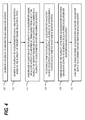
- FIG. 4 illustrates a method for simulating vibration testing of an aircraft engine including generating 400 aircraft engine simulator outputs, by generating simulated speed outputs each representative of an actual speed of a specific component of the aircraft engine, the specific component being one of a fan, a compressor and a turbine, and generating at least one simulation vibration output of a non-aircraft engine source of vibration or an aircraft engine non-shaft source of vibration.
- the method further includes generating 402 accelerometer signal simulator outputs based on the number of aircraft engine simulator outputs, by generating vibration speed outputs for each of the number of accelerometer signal simulator outputs, generating a phase angle output for at least one the number of accelerometer signal simulator outputs, and generating an amplitude output for each of the number of accelerometer signal simulator outputs.
- the method further includes synchronizing 404 at least one of the number of accelerometer signal simulator outputs to a reference timing signal from one of the number of aircraft engine simulator outputs, and generating accelerometer waveform generator outputs, by converting the reference timing signal to an analog reference timing signal, converting each amplitude output to an analog signal output, and synchronizing at least one of the analog signal outputs to generate a synchronized analog signal output.
- the method further includes filtering 406 noise from the number of accelerometer waveform generator outputs and generating filtered accelerometer waveform generator outputs, by receiving each synchronized analog signal outputs and each non-synchronized analog signal outputs to generate corresponding filtered signal outputs.
- the method further includes combining each of the number of filtered accelerometer waveform generator outputs to generate a single filtered accelerometer waveform generator output 408, by receiving the filtered signal outputs that include a vibration speed output, a phase angle output, an amplitude output, a synchronized analog signal output, and a non-synchronized analog signal output, and then generates the single filtered accelerometer waveform generator output from each of these outputs.
- the method further includes converting 410 the single filtered accelerometer waveform generator output to a current charge vibration simulation output.
- the embodiments presented herein allow a user to represent thousands of vibration test conditions to the EMU without risk or damage to the LRU and provides an inexpensive means to prove out any interfaces with aircraft flight deck displays and maintenance systems without expensive flight test on the real aircraft.
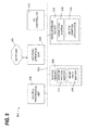
- FIG. 5 shows illustrative computer architecture for a computer 500 capable of executing the software components described herein for implementing the embodiments described above.
- the computer architecture shown in FIG. 5 illustrates a conventional desktop, laptop computer, server computer, tablet computer, smartphone, electronic reader, MP3 player or other digital music device, or any computer configured for use with a system for testing an engine and may be utilized to implement the computer 500 and to execute any of the other software components described herein.
- the computer architecture shown in FIG. 5 includes a central processing unit 502 (CPU) or processor, a system memory 508, including a random access memory 514 (RAM) and a read-only memory (ROM) 516, and a system bus 504 that couples the memory to the CPU 502.
- a basic input/output system (BIOS) containing the basic routines that help to transfer information between elements within the computer 500, such as during startup, is stored in the ROM 516.
- the computer 500 further includes a mass storage device 510 for storing an operating system 518, application programs, and other program modules, which will be described in greater detail below.
- the mass storage device 510 is connected to the CPU 502 through a mass storage controller (not shown) connected to the bus 504.
- the mass storage device 510 and its associated computer-readable media provide non-volatile storage for the computer 500.
- computer-readable media can be any available computer storage media that can be accessed by the computer 500.
- computer-readable storage media may include volatile and non-volatile, removable and non-removable media implemented in any method or technology for storage of information such as computer-readable instructions, data structures, program modules or other data.
- computer-readable storage media includes, but is not limited to, RAM, ROM, EPROM, EEPROM, flash memory or other solid state memory technology, CD-ROM, digital versatile disks (DVD), HD-DVD, BLU-RAY, or other optical storage, magnetic cassettes, magnetic tape, magnetic disk storage or other magnetic storage devices, or any non-transitory medium which can be used to store the desired information and which can be accessed by the computer 500.
- Computer-readable media also encompasses communication media.
- Communication media typically embodies computer readable instructions, data structures, program modules or other data in a modulated data signal such as a carrier wave or other transport mechanism and includes any information delivery media.
- modulated data signal means a signal that has one or more of its characteristics set or changed in such a manner as to encode information in the signal.
- communication media includes wired media such as a wired network or direct-wired connection, and wireless media such as acoustic, RF, infrared and other wireless media. Combinations of the any of the above should also be included within the scope of computer readable media.
- Computer-readable storage media does not encompass communication media.
- the computer 500 may operate in a networked environment using logical connections to remote computers through a network such as the network 520.
- the computer 500 may connect to the network 520 through a network interface unit 506 connected to the bus 504. It should be appreciated that the network interface unit 506 may also be utilized to connect to other types of networks and remote computer systems.
- the computer 500 may also include an input/output controller 512 for receiving and processing input from a number of other devices, including a touchscreen interface 100, keyboard, mouse, joystick, or electronic stylus (not shown in FIG. 5 ). Similarly, an input/output controller may provide output to a display screen, a printer, or other type of output device (also not shown in FIG. 5 ).
- a number of program modules and data files may be stored in the mass storage device 510 and RAM 514 of the computer 500, including an operating system 518 suitable for controlling the operation of a networked desktop, laptop, tablet, smartphone, electronic reader, digital music player, server, or flight computer.
- the mass storage device 510 and RAM 514 may also store one or more program modules.
- the mass storage device 510 and the RAM 514 may store the device control application 522 executable to perform the various operations described above.
- the mass storage device 510 and RAM 514 may also store other program modules and data.
- software applications or modules may, when loaded into the CPU 502 and executed, transform the CPU 502 and the overall computer 500 from a general-purpose computing system into a special-purpose computing system customized to perform the functionality presented herein.
- the CPU 502 may be constructed from any number of transistors or other discrete circuit elements, which may individually or collectively assume any number of states. More specifically, the CPU 502 may operate as one or more finite-state machines, in response to executable instructions contained within the software or modules. These computer-executable instructions may transform the CPU 502 by specifying how the CPU 502 transitions between states, thereby physically transforming the transistors or other discrete hardware elements constituting the CPU 502.
- Encoding the software or modules onto a mass storage device may also transform the physical structure of the mass storage device or associated computer-readable storage media.
- the specific transformation of physical structure may depend on various factors, in different implementations of this description. Examples of such factors may include, but are not limited to: the technology used to implement the computer-readable storage media, whether the computer-readable storage media are characterized as primary or secondary storage, and the like.
- the computer-readable storage media is implemented as semiconductor-based memory
- the software or modules may transform the physical state of the semiconductor memory, when the software is encoded therein.
- the software may transform the states of transistors, capacitors, or other discrete circuit elements constituting the semiconductor memory.
- the computer-readable storage media may be implemented using magnetic or optical technology.
- the software or modules may transform the physical state of magnetic or optical media, when the software is encoded therein. These transformations may include altering the magnetic characteristics of particular locations within given magnetic media. These transformations may also include altering the physical features or characteristics of particular locations within given optical media, to change the optical characteristics of those locations. Other transformations of physical media are possible without departing from the scope and spirit of the present description, with the foregoing examples provided only to facilitate this discussion.
- a system for testing an engine, the system comprising: a plurality of simulated accelerometers 300, 302 and 304, each simulated accelerometer 300, 302, 304 including: an engine simulator that generates a plurality of engine simulator outputs 312; an accelerometer signal simulator 320 that receives the plurality of engine simulator outputs 312, 314, 316 and generates a plurality of accelerometer signal simulator 320 outputs 320, 324, 328; an accelerometer waveform generator 350 that receives the plurality of accelerometer signal simulator 320 outputs and synchronizes at least one of the plurality of accelerometer signal simulator 320 outputs to a reference timing signal from one of the plurality of engine simulator outputs 312, the accelerometer waveform generator 350 generating a plurality of accelerometer waveform generator outputs 408; a filter section that receives and filters noise from the plurality of accelerometer waveform generator outputs 408 to generate a plurality of filtered accelerometer waveform generator outputs
- the system includes the plurality of simulated accelerometers 300, 302 and 304 represent a plurality of corresponding actual accelerometers placed at specific test locations on the engine and provide simulated vibration signal output to the monitor unit consistent with the plurality of corresponding actual accelerometers at each specific test location over various engine speeds.
- the system includes wherein the engine simulator further comprises: a plurality of simulated speed outputs 312, 314 and 316 each representative of an actual speed of a specific component of an aircraft engine 12, the specific component being one of a fan 14, a compressor 16 and a turbine 20; and simulated vibration output 318 of one of a non-aircraft engine 12 source of vibration and an aircraft engine 12 non-shaft source of vibration.
- the system includes wherein the accelerometer signal simulator 320 further includes: a plurality of vibration speed simulators 322, 324, 326 and 328 that receive each of the plurality of simulated speed outputs 312, 314 and 316 and the at least one simulated vibration output 318 and generates a respective vibration speed output; a plurality of phase angle manipulators 330, 332 and 334 that receive each respective vibration speed output and inserts a phase angle value to generate a respective phase angle output; and a plurality of amplitude manipulators 336, 338, 340 and 342 that receive each respective phase angle output and modifies an amplitude value to generate a respective amplitude output.
- a plurality of vibration speed simulators 322, 324, 326 and 328 that receive each of the plurality of simulated speed outputs 312, 314 and 316 and the at least one simulated vibration output 318 and generates a respective vibration speed output
- a plurality of phase angle manipulators 330, 332 and 334 that receive each respective vibration speed output and inserts
- the system include the accelerometer waveform generator 350 that further includes: a digital-to-analog D/A converter 352 that receives and converts the reference timing signal to an analog reference timing signal; a plurality of D/A converters that convert each respective amplitude output to a respective analog signal output; and a synchronized pulse generator that receives the analog reference timing signal and synchronizes at least two of the analog signal outputs via the plurality of D/A converters to generate a respective synchronized analog signal output.
- a digital-to-analog D/A converter 352 that receives and converts the reference timing signal to an analog reference timing signal
- a plurality of D/A converters that convert each respective amplitude output to a respective analog signal output
- a synchronized pulse generator that receives the analog reference timing signal and synchronizes at least two of the analog signal outputs via the plurality of D/A converters to generate a respective synchronized analog signal output.
- the system includes the filter section 372, 374, 376 and 378 including a plurality of filters that receive each respective synchronized analog signal outputs and each non-synchronized respective analog signal outputs to generate corresponding filtered signal outputs.
- the system includes the mixer 380 receiving the corresponding filtered signal outputs including, a vibration speed output, a phase angle output, an amplitude output, a synchronized analog signal output, and a non-synchronized analog signal output, and generating the single filtered accelerometer waveform generator output 408 from each of these outputs.
- a simulated engine accelerometer including: an engine simulator that generates a plurality of engine simulator outputs 312; an accelerometer signal simulator 320 that receives the plurality of engine simulator outputs 312, 314, 316 and generates a plurality of accelerometer signal simulator 320 outputs 322, 324, 328; an accelerometer waveform generator 350 that receives the plurality of accelerometer signal simulator 320 outputs and synchronizes at least one of the plurality of accelerometer signal simulator 320 outputs to a reference timing signal from one of the plurality of engine simulator outputs 312, the accelerometer waveform generator 350 generating a plurality of accelerometer waveform generator outputs 408; a filter section 372, 374, 376 and 378 that receives and filters noise from the plurality of accelerometer waveform generator outputs 408 to generate a plurality of filtered accelerometer waveform generator outputs 408; a mixer 380 that receives and combines each of the plurality of filtered accelerometer waveform generator outputs 408 to generate a single filtered
- the simulated engine accelerometer includes the simulated engine accelerometer represent an actual accelerometer placed at a specific test location on the engine and provides simulated vibration signal output to an monitor unit consistent with the actual accelerometer at the specific test location over various engine speeds.
- the simulated aircraft engine 12 accelerometer according to claim 10, wherein the accelerometer signal simulator 320 further includes: a plurality of vibration speed simulators 322, 324, 326 and 328 that receive each of the plurality of simulated speed outputs 312, 314 and 316 and the at least one simulation vibration output 318 and generates a respective vibration speed output; a plurality of phase angle manipulators 330, 332 and 334 that receive each respective vibration speed output and inserts a phase angle value to generate a respective phase angle output; and a plurality of amplitude manipulators 336, 338, 340 and 342 that receive each respective phase angle output and modifies an amplitude value to generate a respective amplitude output.
- a plurality of vibration speed simulators 322, 324, 326 and 328 that receive each of the plurality of simulated speed outputs 312, 314 and 316 and the at least one simulation vibration output 318 and generates a respective vibration speed output
- a plurality of phase angle manipulators 330, 332 and 334 that receive each respective
- the simulated aircraft engine 12 accelerometer includes, the accelerometer waveform generator 350 further includes: a digital-to-analog D/A converter 352 that receives and converts the reference timing signal to an analog reference timing signal; a plurality of D/A converters that convert each respective amplitude output to a respective analog signal output; and a synchronized pulse generator that receives the analog reference timing signal and synchronizes at least two of the analog signal outputs via the plurality of D/A converters to generate a respective synchronized analog signal output.
- a digital-to-analog D/A converter 352 that receives and converts the reference timing signal to an analog reference timing signal
- a plurality of D/A converters that convert each respective amplitude output to a respective analog signal output
- a synchronized pulse generator that receives the analog reference timing signal and synchronizes at least two of the analog signal outputs via the plurality of D/A converters to generate a respective synchronized analog signal output.
- the simulated aircraft engine 12 accelerometer includes the filter section 372, 374, 376 and 378 including a plurality of filters that receive each respective synchronized analog signal outputs and each non-synchronized respective analog signal outputs to generate corresponding filtered signal outputs.
- the simulated aircraft engine 12 accelerometer includes the mixer 380 receiving the corresponding filtered signal outputs including a vibration speed output, a phase angle output, an amplitude output, a synchronized analog signal output, and a non-synchronized analog signal output, the method further comprising generating the single filtered accelerometer waveform generator 350 output from each of these outputs.
- a method for simulating vibration testing of an engine, the method including: generating a plurality of engine simulator outputs 312; generating a plurality of accelerometer signal simulator 320 outputs based on the plurality of engine simulator outputs 312, 314, 316; synchronizing 404 at least one of the plurality of accelerometer signal simulator 320 outputs to a reference timing signal from one of the plurality of engine simulator outputs 312, 314, 316, and generating a plurality of accelerometer waveform generator 350 outputs; filtering noise from the plurality of accelerometer waveform generator 350 outputs and generating a plurality of filtered accelerometer waveform generator 350 outputs; combining each of the plurality of filtered accelerometer waveform generator 350 outputs to generate a single filtered accelerometer waveform generator 350 output; and converting 410 the single filtered accelerometer waveform generator 350 output to a current charge vibration simulation output.
- the method includes wherein generating the plurality of engine simulator outputs 312 further includes: generating a plurality of simulated speed outputs 312, 314 and 316 each representative of an actual speed of a specific component of an aircraft engine 12, the specific component being one of a fan 14, a compressor 16 and a turbine 20; and generating at least one simulation vibration output 318 of one of a non-aircraft engine 12 source of vibration and an aircraft engine 12 non-shaft source of vibration.
- the method includes wherein generating the plurality of accelerometer signal simulator 320 outputs further includes: generating vibration speed outputs for each of the plurality of accelerometer signal simulator 320 outputs; generate a phase angle output for at least one the plurality of accelerometer signal simulator 320 outputs; and generate an amplitude output for each of the plurality of accelerometer signal simulator 320 outputs.
- the method includes wherein synchronizing 404 the at least one of the plurality of accelerometer signal simulator 320 outputs further includes: converting the reference timing signal to an analog reference timing signal; converting each amplitude output to an analog signal output; and synchronizing 404 at least two of the analog signal outputs to generate a synchronized analog signal output.
- the filtering noise from the plurality of accelerometer waveform generator 350 further includes: receiving each synchronized analog signal outputs and each non-synchronized analog signal outputs to generate filtered signal outputs.
- the method includes wherein combining each of the plurality of filtered accelerometer waveform generator 350 outputs further includes: receiving the filtered signal outputs including a vibration speed output, a phase angle output, an amplitude output, a synchronized analog signal output, and a non-synchronized analog signal output; and generating the single filtered accelerometer waveform generator 350 output from each of these outputs.
Landscapes
- Physics & Mathematics (AREA)
- General Physics & Mathematics (AREA)
- Engineering & Computer Science (AREA)
- Geometry (AREA)
- Chemical & Material Sciences (AREA)
- Combustion & Propulsion (AREA)
- Theoretical Computer Science (AREA)
- Mathematical Optimization (AREA)
- Mathematical Analysis (AREA)
- Pure & Applied Mathematics (AREA)
- Computer Hardware Design (AREA)
- Evolutionary Computation (AREA)
- General Engineering & Computer Science (AREA)
- Computational Mathematics (AREA)
- Testing Of Engines (AREA)
- Testing Of Devices, Machine Parts, Or Other Structures Thereof (AREA)
Abstract
Description
- The general field of the embodiments presented herein is directed to simulation of aircraft engine testing, and more particularly to a system, method and apparatus of multiple accelerometer simulation for aircraft engine and engine component testing.
- Existing solutions to aircraft engine testing include testing flight test aircraft by adding or removing balance weights to the fan and low pressure turbine. The drawbacks to this method of testing are that it is expensive to run as it requires fuel to burn during testing, it requires additional hours to add and remove weights, and it introduces a potential to damage engine and flight test aircraft. Another method includes generating signals using a signal generator to a vibration measuring Line Replacement Unit (LRU). However, drawbacks to this method include the requirement of manual calculation for each test condition, and that one signal may be generated at a time, which limits the evaluation to only one vibration type at a time. This method also requires manual manipulation and validation of each tested condition.
- There is a need to provide a test system with the ability to generate accelerometer signals that replicate the complexities of multiple aircraft engine accelerometers in the field in such a manner to generate these signals in a controlled laboratory test environment. It is with respect to these and other considerations that the disclosure herein is presented.
- It should be appreciated that this Summary is provided to introduce a selection of concepts in a simplified form that are further described below in the Detailed Description. This Summary is not intended to be used to limit the scope of the claimed subject matter.
- In one embodiment disclosed herein, an accelerometer simulation system for testing an engine includes a number of simulated accelerometers and a monitor unit that receives current charge vibration simulation output from each simulated accelerometer to measure a simulated total engine vibration. Each simulated accelerometer includes an engine simulator that generates a number of engine simulator outputs, and an accelerometer signal simulator that receives the engine simulator outputs and that generates a number of accelerometer signal simulator outputs. The simulated accelerometer further includes an accelerometer waveform generator that receives the accelerometer signal simulator outputs and synchronizes at least one of the accelerometer signal simulator outputs to a reference timing signal from the engine simulator outputs, where the accelerometer waveform generator generates a number of accelerometer waveform generator outputs. The simulated accelerometer further includes a filter section that receives and filters noise from the accelerometer waveform generator outputs to generate a number of filtered accelerometer waveform generator outputs. A mixer receives and combines each of the filtered accelerometer waveform generator outputs to generate a single filtered accelerometer waveform generator output. A charge converter receives and converts the single filtered accelerometer waveform generator output to a current charge vibration simulation output.
- In another embodiment disclosed herein, a simulated engine accelerometer includes an engine simulator that generates a number of engine simulator outputs, and an accelerometer signal simulator that receives the engine simulator outputs and generates a number of accelerometer signal simulator outputs. The engine simulator further includes an accelerometer waveform generator that receives the accelerometer signal simulator outputs and synchronizes at least one of the accelerometer signal simulator outputs to a reference timing signal from one of the engine simulator outputs, where the accelerometer waveform generator generates a number of accelerometer waveform generator outputs. The simulated accelerometer further includes a filter section that receives and filters noise from the accelerometer waveform generator outputs to generate a number of filtered accelerometer waveform generator outputs. The engine simulator further includes a mixer that receives and combines each of the filtered accelerometer waveform generator outputs to generate a single filtered accelerometer waveform generator output, and a charge converter that receives and converts the single filtered accelerometer waveform generator output to a current charge vibration simulation output.
- In another embodiment disclosed herein, a method for simulating vibration testing of an engine includes generating a number of engine simulator outputs, generating a number of accelerometer signal simulator outputs based on the engine simulator outputs, and synchronizing at least one of the accelerometer signal simulator outputs to a reference timing signal from one of the engine simulator outputs to generate a number of accelerometer waveform generator outputs. The method further includes filtering noise from the accelerometer waveform generator outputs and generating a number of filtered accelerometer waveform generator outputs, combining each of the filtered accelerometer waveform generator outputs to generate a single filtered accelerometer waveform generator output, and converting the single filtered accelerometer waveform generator output to a current charge vibration simulation output.
- The features, functions, and advantages that have been discussed can be achieved independently in various embodiments of the present disclosure or may be combined in yet other embodiments, further details of which can be seen with reference to the following description and drawings.
- The embodiments presented herein will become more fully understood from the detailed description and the accompanying drawings, wherein:
-
FIG. 1 is an illustration of an aircraft incorporating a turbojet engine in accordance with a preferred embodiment presented herein; -
FIG. 2 is a perspective cut-away view of a turbojet shown inFIG. 1 , in accordance with a preferred embodiment presented herein; -
FIG. 3 illustrates one embodiment of an accelerometer simulation system for testing an aircraft engine according to at least one embodiment disclosed herein; -
FIG. 4 illustrates a logic flow diagram of an embodiment of an accelerometer simulation testing method of an aircraft engine according to at least one embodiment disclosed herein; and -
FIG. 5 is a computer architecture diagram showing an illustrative computer hardware and software architecture for a computing system capable of implementing the embodiments presented herein. - The following detailed description is directed to providing a system that allows the maximum ability to test airplane level integration of a Line Replaceable Unit (LRU) which monitors engine vibration. Typical LRUs which have this function include the Airborne Vibration Monitor (AVM) installed in the airplane's avionics suite, the Engine Monitor Unit (EMU) mounted on the engine, and a Health and Usage Monitor System (HUMS) in a rotorcraft, although this list of LRUs is not exhaustive, and alternative semantics exist. The design of this system can be applied or tailored to similar LRUs installed on other engines/aircraft types/rotorcraft. Airplane level integration testing is focused on validation and verification of Engine Indication displays, events, messages as well as interaction with diagnostic and prognostic maintenance operations related to an engine vibration system. The LRU uses accelerometers to measure vibrations in an
aircraft engine 12. With reference toFIGS. 1 and2 , anaircraft 10 includes one ormore engines aircraft 10 through the air. For example, theengine 12 may be a turbojet, turbofan, or any engine having rotating parts or otherwise. For instance,FIG. 2 illustrates a representativeturbofan jet engine 12 including afan section 14, acompressor section 16, acombustion section 18 and aturbine section 20. Thefan section 14,compressor section 16 andturbine section 20 are mounted on concentrically disposed shafts at 22. Theengine 12 may be comprised of one or more shafts. Note that these shafts may or may not be concentric with each other, and that any of the shaft speeds may or may not be independent with any of the other shaft speeds. Rotating components linked to a shaft, such as couplers and gearboxes (not shown), may rotate a different speeds than the shafts. Althoughturbofan jet engine 12 is an exemplary application of the system and method described herein, many other types of engines may be used to obtain the benefits of the system and method described herein. - The airplane integration level testing requires monitoring tracked order vibration, broadband vibration and engine trim and balance. Tracked order vibration monitor integration testing requires the ability to independently control a magnitude of vibrations experienced by multiple accelerometers located at various places with the
engine 12 at various sections, e.g., thefan section 14, thecompressor section 16 and theturbine section 20. Engine trim and balance requires the ability of the LRU to derive the phase angle of the maximum vibration as related to the once per revolution indication either embedded within the engine rotor speed signal or via a separate once-per-rev signal. The engine accelerometer vibration signals are a function of the vibration of the multiple components of an engine including thefan 14,compressor 16,turbine 20, as well as many others within the engine and those induced in an integrated airframe environment. Since many of these engine components in the engine run at different rotational speeds, the engine vibration signal is mainly a function of the different rotational speeds and the vibration magnitudes associated with those speeds. Each engine accelerometer experiences the vibration of each of these engine speeds, and thus the LRU must be able to differentiate the influence each engine component. Therefore, this requires a test system to provide the ability to generate accelerometer signals that replicate these complexities. - The following provides an overview of the Engine Vibration Test System (EVTS), as shown in
Fig. 3 . The EVTS simulates an engine accelerometer's input to an LRU, such as the EMU. The EVTS is comprised of five formal parts for each simulated accelerometer: signal generators, synchronization circuits, charge converter circuits, mixer circuits, and engine simulation interfaces. The signal generator is comprised of a series of Versa Module Eurocard (VME) boards to produce individual waveforms representing vibrations related to each engine component, (fan, turbine, compressor, gearbox, etc.), as well as other sources of vibrations, (generators, pumps, etc.). Although the VME boards are described herein, other types of signal generating boards may be used that accomplish a similar function. The synchronization circuit synchronizes the VME Board Vibration Waveform Output for the Fan to another signal which represents the Fan speed which the EMU observes independently. The EMU correlates the engine fan speed and the synchronized accelerometer input to devise the phase angle in support of the engine trim and balance. The Mixer circuit combines synchronized engine fan waveforms with non-synchronized waveforms (turbine, compressor, pumps, generators, etc.). The charge converter circuit converts the waveform into a charge that represents the accelerometer. The simulation computes all the engine speeds, and computes all the voltages, frequencies, and phase angle manipulations that are sent to the signal generators. Overall, the EVTS allows the user to represent thousands of vibration test conditions to the EMU without risk or damage to the EMU and provides an inexpensive means to prove out any interfaces with aircraft flight deck displays, maintenance systems, without expensive flight test on the real aircraft. -
FIG. 3 illustrates one embodiment presented herein for an accelerometer simulation system for testing an aircraft engine includes simulated accelerometers, e.g., accelerometer "1" 300, accelerometer "2" 302, and accelerometer "N" 304. Each simulated accelerometer includes a number of components used to create a simulated signal that is transmitted and processed by an Engine Monitor Unit (EMU) 390. The number ofsimulated accelerometers aircraft engine 12 and provide simulated vibration signal output to theEMU 390. - The first component for each of the number of simulated accelerometers is an
aircraft engine simulator 310 that generates aircraft engine simulator outputs 312, 314, 316 and 318. Each of these outputs from this stage are representative of an actual speed of a specific component of an aircraft engine, e.g.,speed # speed # speed # aircraft engine 12. The speed related components of the aircraft engine may be from any portion of the fan, compressor or turbine assemblies, whereas, the non-aircraft engine/aircraft engine non-shaft vibration component may be any source of vibration that originates from sources other than theaircraft engine 12 or are not speed dependent on parts within the aircraft engine. - Another component for each of the number of simulated accelerometers is an
accelerometer signal simulator 320 that receives the number of aircraft engine simulator outputs, e.g., the speed basedoutputs vibration speed simulators simulated speed outputs simulated vibration output 318, and generate a respective vibration speed output. Some of these outputs (from 322, 324 and 328) may be received atphase angle manipulators central shafts 22.Amplitude manipulators vibration speed # 3 without any phase angle manipulation), and modifies an amplitude value to generate a respective amplitude output. - Another component for each of the number of simulated accelerometers is an
accelerometer waveform generator 350 that receives the number of accelerometer signal simulator outputs and synchronizes at least one accelerometer signal simulator output to a reference timing signal from one of the number of aircraft engine simulator outputs, for example, fromspeed # accelerometer waveform generator 350 generates accelerometer waveform generator outputs by first using a digital-to-analog (D/A)converter 352 to receive and convert the reference timing signal fromengine simulation 310speed # A # 1 356, D/A #2 358, D/A #3 360 and D/A #N 362 convert each respective amplitude output to a respective analog signal output and asynchronized pulse generator 354 receives the analog reference timing signal and synchronizes at least one of the analog signal outputs via the number of D/A converters, e.g., D/A #1 356, D/A #2 358 and D/A #N 362, to generate a respective synchronized analog signal output. - Another component for each of the number of simulated accelerometers includes a filter section, 372, 374, 376 and 378 that receives and filters noise from the number of accelerometer waveform generator outputs, e.g., from 356, 358 and 362 and each non-synchronized respective analog signal outputs, e.g., from 360, to generate filtered accelerometer waveform generator outputs.
- Each simulated accelerometer further includes a
mixer 380 that receives and combines each of the number of filtered accelerometer waveform generator outputs that include a vibration speed output, a phase angle output, an amplitude output, a synchronized analog signal output, and a non-synchronized analog signal output, thereby generating the single filtered accelerometer waveform generator output. - Finally, a
charge converter 382 receives the output from themixer 380 and converts the single filtered accelerometer waveform generator output to a current charge vibration simulation output. Anengine monitoring unit 390 receives each current charge vibration simulation output from each of the number of simulated accelerometers to measure a simulated total aircraft engine vibration. -
FIG. 4 illustrates a method for simulating vibration testing of an aircraft engine including generating 400 aircraft engine simulator outputs, by generating simulated speed outputs each representative of an actual speed of a specific component of the aircraft engine, the specific component being one of a fan, a compressor and a turbine, and generating at least one simulation vibration output of a non-aircraft engine source of vibration or an aircraft engine non-shaft source of vibration. - The method further includes generating 402 accelerometer signal simulator outputs based on the number of aircraft engine simulator outputs, by generating vibration speed outputs for each of the number of accelerometer signal simulator outputs, generating a phase angle output for at least one the number of accelerometer signal simulator outputs, and generating an amplitude output for each of the number of accelerometer signal simulator outputs.
- The method further includes synchronizing 404 at least one of the number of accelerometer signal simulator outputs to a reference timing signal from one of the number of aircraft engine simulator outputs, and generating accelerometer waveform generator outputs, by converting the reference timing signal to an analog reference timing signal, converting each amplitude output to an analog signal output, and synchronizing at least one of the analog signal outputs to generate a synchronized analog signal output.
- The method further includes filtering 406 noise from the number of accelerometer waveform generator outputs and generating filtered accelerometer waveform generator outputs, by receiving each synchronized analog signal outputs and each non-synchronized analog signal outputs to generate corresponding filtered signal outputs.
- The method further includes combining each of the number of filtered accelerometer waveform generator outputs to generate a single filtered accelerometer
waveform generator output 408, by receiving the filtered signal outputs that include a vibration speed output, a phase angle output, an amplitude output, a synchronized analog signal output, and a non-synchronized analog signal output, and then generates the single filtered accelerometer waveform generator output from each of these outputs. The method further includes converting 410 the single filtered accelerometer waveform generator output to a current charge vibration simulation output. - Thus, the embodiments presented herein allow a user to represent thousands of vibration test conditions to the EMU without risk or damage to the LRU and provides an inexpensive means to prove out any interfaces with aircraft flight deck displays and maintenance systems without expensive flight test on the real aircraft.
-
FIG. 5 shows illustrative computer architecture for acomputer 500 capable of executing the software components described herein for implementing the embodiments described above. The computer architecture shown inFIG. 5 illustrates a conventional desktop, laptop computer, server computer, tablet computer, smartphone, electronic reader, MP3 player or other digital music device, or any computer configured for use with a system for testing an engine and may be utilized to implement thecomputer 500 and to execute any of the other software components described herein. - The computer architecture shown in
FIG. 5 includes a central processing unit 502 (CPU) or processor, asystem memory 508, including a random access memory 514 (RAM) and a read-only memory (ROM) 516, and asystem bus 504 that couples the memory to theCPU 502. A basic input/output system (BIOS) containing the basic routines that help to transfer information between elements within thecomputer 500, such as during startup, is stored in theROM 516. Thecomputer 500 further includes amass storage device 510 for storing anoperating system 518, application programs, and other program modules, which will be described in greater detail below. - The
mass storage device 510 is connected to theCPU 502 through a mass storage controller (not shown) connected to thebus 504. Themass storage device 510 and its associated computer-readable media provide non-volatile storage for thecomputer 500. Although the description of computer-readable media contained herein refers to a mass storage device, such as a hard disk or CD-ROM drive, it should be appreciated by those skilled in the art that computer-readable storage media can be any available computer storage media that can be accessed by thecomputer 500. - By way of example, and not limitation, computer-readable storage media may include volatile and non-volatile, removable and non-removable media implemented in any method or technology for storage of information such as computer-readable instructions, data structures, program modules or other data. For example, computer-readable storage media includes, but is not limited to, RAM, ROM, EPROM, EEPROM, flash memory or other solid state memory technology, CD-ROM, digital versatile disks (DVD), HD-DVD, BLU-RAY, or other optical storage, magnetic cassettes, magnetic tape, magnetic disk storage or other magnetic storage devices, or any non-transitory medium which can be used to store the desired information and which can be accessed by the
computer 500. - It should be appreciated that the computer-readable media disclosed herein also encompasses communication media. Communication media typically embodies computer readable instructions, data structures, program modules or other data in a modulated data signal such as a carrier wave or other transport mechanism and includes any information delivery media. The term "modulated data signal" means a signal that has one or more of its characteristics set or changed in such a manner as to encode information in the signal. By way of example, and not limitation, communication media includes wired media such as a wired network or direct-wired connection, and wireless media such as acoustic, RF, infrared and other wireless media. Combinations of the any of the above should also be included within the scope of computer readable media. Computer-readable storage media does not encompass communication media.
- According to various embodiments, the
computer 500 may operate in a networked environment using logical connections to remote computers through a network such as thenetwork 520. Thecomputer 500 may connect to thenetwork 520 through anetwork interface unit 506 connected to thebus 504. It should be appreciated that thenetwork interface unit 506 may also be utilized to connect to other types of networks and remote computer systems. Thecomputer 500 may also include an input/output controller 512 for receiving and processing input from a number of other devices, including a touchscreen interface 100, keyboard, mouse, joystick, or electronic stylus (not shown inFIG. 5 ). Similarly, an input/output controller may provide output to a display screen, a printer, or other type of output device (also not shown inFIG. 5 ). - As mentioned briefly above, a number of program modules and data files may be stored in the
mass storage device 510 andRAM 514 of thecomputer 500, including anoperating system 518 suitable for controlling the operation of a networked desktop, laptop, tablet, smartphone, electronic reader, digital music player, server, or flight computer. Themass storage device 510 andRAM 514 may also store one or more program modules. In particular, themass storage device 510 and theRAM 514 may store thedevice control application 522 executable to perform the various operations described above. Themass storage device 510 andRAM 514 may also store other program modules and data. - In general, software applications or modules may, when loaded into the
CPU 502 and executed, transform theCPU 502 and theoverall computer 500 from a general-purpose computing system into a special-purpose computing system customized to perform the functionality presented herein. TheCPU 502 may be constructed from any number of transistors or other discrete circuit elements, which may individually or collectively assume any number of states. More specifically, theCPU 502 may operate as one or more finite-state machines, in response to executable instructions contained within the software or modules. These computer-executable instructions may transform theCPU 502 by specifying how theCPU 502 transitions between states, thereby physically transforming the transistors or other discrete hardware elements constituting theCPU 502. - Encoding the software or modules onto a mass storage device may also transform the physical structure of the mass storage device or associated computer-readable storage media. The specific transformation of physical structure may depend on various factors, in different implementations of this description. Examples of such factors may include, but are not limited to: the technology used to implement the computer-readable storage media, whether the computer-readable storage media are characterized as primary or secondary storage, and the like. For example, if the computer-readable storage media is implemented as semiconductor-based memory, the software or modules may transform the physical state of the semiconductor memory, when the software is encoded therein. For example, the software may transform the states of transistors, capacitors, or other discrete circuit elements constituting the semiconductor memory.
- As another example, the computer-readable storage media may be implemented using magnetic or optical technology. In such implementations, the software or modules may transform the physical state of magnetic or optical media, when the software is encoded therein. These transformations may include altering the magnetic characteristics of particular locations within given magnetic media. These transformations may also include altering the physical features or characteristics of particular locations within given optical media, to change the optical characteristics of those locations. Other transformations of physical media are possible without departing from the scope and spirit of the present description, with the foregoing examples provided only to facilitate this discussion.
- Furthermore, in accordance with the figures and the text, in one aspect, a system is disclosed for testing an engine, the system comprising: a plurality of simulated accelerometers 300, 302 and 304, each simulated accelerometer 300, 302, 304 including: an engine simulator that generates a plurality of engine simulator outputs 312; an accelerometer signal simulator 320 that receives the plurality of engine simulator outputs 312, 314, 316 and generates a plurality of accelerometer signal simulator 320 outputs 320, 324, 328; an accelerometer waveform generator 350 that receives the plurality of accelerometer signal simulator 320 outputs and synchronizes at least one of the plurality of accelerometer signal simulator 320 outputs to a reference timing signal from one of the plurality of engine simulator outputs 312, the accelerometer waveform generator 350 generating a plurality of accelerometer waveform generator outputs 408; a filter section that receives and filters noise from the plurality of accelerometer waveform generator outputs 408 to generate a plurality of filtered accelerometer waveform generator outputs 408; a mixer 380 that receives and combines each of the plurality of filtered accelerometer waveform generator outputs 408 to generate a single filtered accelerometer waveform generator output 408; and a charge converter 382 that receives and converts the single filtered accelerometer waveform generator output 408 to a current charge vibration simulation output; and a monitor unit that receives each current charge vibration simulation output from each of the plurality of simulated accelerometers 300, 302 and 304 to measure a simulated total engine vibration.
- In one variant, the system includes the plurality of
simulated accelerometers simulated speed outputs aircraft engine 12, the specific component being one of afan 14, acompressor 16 and aturbine 20; andsimulated vibration output 318 of one of anon-aircraft engine 12 source of vibration and anaircraft engine 12 non-shaft source of vibration. - In yet another variant, the system includes wherein the
accelerometer signal simulator 320 further includes: a plurality ofvibration speed simulators simulated speed outputs simulated vibration output 318 and generates a respective vibration speed output; a plurality ofphase angle manipulators amplitude manipulators - In still another variant, the system include the
accelerometer waveform generator 350 that further includes: a digital-to-analog D/A converter 352 that receives and converts the reference timing signal to an analog reference timing signal;
a plurality of D/A converters that convert each respective amplitude output to a respective analog signal output; and a synchronized pulse generator that receives the analog reference timing signal and synchronizes at least two of the analog signal outputs via the plurality of D/A converters to generate a respective synchronized analog signal output. - In one example, the system includes the
filter section mixer 380 receiving the corresponding filtered signal outputs including, a vibration speed output, a phase angle output, an amplitude output, a synchronized analog signal output, and a non-synchronized analog signal output, and generating the single filtered accelerometerwaveform generator output 408 from each of these outputs. - In one aspect, a simulated engine accelerometer is disclosed including: an engine simulator that generates a plurality of engine simulator outputs 312; an
accelerometer signal simulator 320 that receives the plurality of engine simulator outputs 312, 314, 316 and generates a plurality ofaccelerometer signal simulator 320outputs accelerometer waveform generator 350 that receives the plurality ofaccelerometer signal simulator 320 outputs and synchronizes at least one of the plurality ofaccelerometer signal simulator 320 outputs to a reference timing signal from one of the plurality of engine simulator outputs 312, theaccelerometer waveform generator 350 generating a plurality of accelerometerwaveform generator outputs 408; afilter section waveform generator outputs 408 to generate a plurality of filtered accelerometerwaveform generator outputs 408; amixer 380 that receives and combines each of the plurality of filtered accelerometerwaveform generator outputs 408 to generate a single filtered accelerometerwaveform generator output 408; and acharge converter 382 that receives and converts the single filtered accelerometerwaveform generator output 408 to a current charge vibration simulation output. - In one variant, the simulated engine accelerometer includes the simulated engine accelerometer represent an actual accelerometer placed at a specific test location on the engine and provides simulated vibration signal output to an monitor unit consistent with the actual accelerometer at the specific test location over various engine speeds. In another variant, the
simulated aircraft engine 12 accelerometer according to claim 8, wherein the engine simulator further includes: a plurality ofsimulated speed outputs aircraft engine 12, the specific component being one of afan 14, acompressor 16 and aturbine 20; andsimulated vibration output 318 of one of anon-aircraft engine 12 source of vibration and an engine non-shaft source of vibration. - In one example, the
simulated aircraft engine 12 accelerometer according toclaim 10, wherein theaccelerometer signal simulator 320 further includes: a plurality ofvibration speed simulators simulated speed outputs simulation vibration output 318 and generates a respective vibration speed output; a plurality ofphase angle manipulators amplitude manipulators - In another example, the
simulated aircraft engine 12 accelerometer includes, theaccelerometer waveform generator 350 further includes: a digital-to-analog D/A converter 352 that receives and converts the reference timing signal to an analog reference timing signal; a plurality of D/A converters that convert each respective amplitude output to a respective analog signal output; and a synchronized pulse generator that receives the analog reference timing signal and synchronizes at least two of the analog signal outputs via the plurality of D/A converters to generate a respective synchronized analog signal output. In still another example, thesimulated aircraft engine 12 accelerometer includes thefilter section simulated aircraft engine 12 accelerometer includes themixer 380 receiving the corresponding filtered signal outputs including a vibration speed output, a phase angle output, an amplitude output, a synchronized analog signal output, and a non-synchronized analog signal output, the method further comprising generating the single filteredaccelerometer waveform generator 350 output from each of these outputs. - In one aspect, a method is disclosed for simulating vibration testing of an engine, the method including: generating a plurality of engine simulator outputs 312; generating a plurality of
accelerometer signal simulator 320 outputs based on the plurality of engine simulator outputs 312, 314, 316; synchronizing 404 at least one of the plurality ofaccelerometer signal simulator 320 outputs to a reference timing signal from one of the plurality of engine simulator outputs 312, 314, 316, and generating a plurality ofaccelerometer waveform generator 350 outputs; filtering noise from the plurality ofaccelerometer waveform generator 350 outputs and generating a plurality of filteredaccelerometer waveform generator 350 outputs;
combining each of the plurality of filteredaccelerometer waveform generator 350 outputs to generate a single filteredaccelerometer waveform generator 350 output; and converting 410 the single filteredaccelerometer waveform generator 350 output to a current charge vibration simulation output. - In one example, the method includes wherein generating the plurality of
engine simulator outputs 312 further includes: generating a plurality ofsimulated speed outputs aircraft engine 12, the specific component being one of afan 14, acompressor 16 and aturbine 20; and generating at least onesimulation vibration output 318 of one of anon-aircraft engine 12 source of vibration and anaircraft engine 12 non-shaft source of vibration. In another example, the method includes wherein generating the plurality ofaccelerometer signal simulator 320 outputs further includes: generating vibration speed outputs for each of the plurality ofaccelerometer signal simulator 320 outputs; generate a phase angle output for at least one the plurality ofaccelerometer signal simulator 320 outputs; and generate an amplitude output for each of the plurality ofaccelerometer signal simulator 320 outputs. - In yet another example, the method includes wherein synchronizing 404 the at least one of the plurality of
accelerometer signal simulator 320 outputs further includes: converting the reference timing signal to an analog reference timing signal; converting each amplitude output to an analog signal output; and synchronizing 404 at least two of the analog signal outputs to generate a synchronized analog signal output. In one instance, the method includes wherein the filtering noise from the plurality ofaccelerometer waveform generator 350 further includes: receiving each synchronized analog signal outputs and each non-synchronized analog signal outputs to generate filtered signal outputs. In another instance, the method includes wherein combining each of the plurality of filteredaccelerometer waveform generator 350 outputs further includes: receiving the filtered signal outputs including a vibration speed output, a phase angle output, an amplitude output, a synchronized analog signal output, and a non-synchronized analog signal output; and generating the single filteredaccelerometer waveform generator 350 output from each of these outputs. - The subject matter described above is provided by way of illustration only and should not be construed as limiting. Various modifications and changes may be made to the subject matter described herein without following the example embodiments and applications illustrated and described, and without departing from the true spirit and scope of the present disclosure, which is set forth in the following claims.
Claims (10)
- A system for testing an engine, the system comprising:a plurality of simulated accelerometers (300, 302 and 304), each simulated accelerometer (300, 302, 304) including:an engine simulator that generates a plurality of engine simulator outputs (312);an accelerometer signal simulator (320) that receives the plurality of engine simulator outputs (312, 314, 316) and generates a plurality of accelerometer signal simulator (320) outputs (320, 324, 328);an accelerometer waveform generator (350) that receives the plurality of accelerometer signal simulator (320) outputs and synchronizes at least one of the plurality of accelerometer signal simulator (320) outputs to a reference timing signal from one of the plurality of engine simulator outputs (312), the accelerometer waveform generator (350) generating a plurality of accelerometer waveform generator outputs (408);a filter section that receives and filters noise from the plurality of accelerometer waveform generator outputs (408) to generate a plurality of filtered accelerometer waveform generator outputs (408);a mixer (380) that receives and combines each of the plurality of filtered accelerometer waveform generator outputs (408) to generate a single filtered accelerometer waveform generator output (408); anda charge converter (382) that receives and converts the single filtered accelerometer waveform generator output (408) to a current charge vibration simulation output; anda monitor unit that receives each current charge vibration simulation output from each of the plurality of simulated accelerometers (300, 302 and 304) to measure a simulated total engine vibration.
- The system according to claim 1, the plurality of simulated accelerometers (300, 302 and 304) represent a plurality of corresponding actual accelerometers placed at specific test locations on the engine and provide simulated vibration signal output to the monitor unit consistent with the plurality of corresponding actual accelerometers at each specific test location over various engine speeds; wherein the engine simulator further comprises:a plurality of simulated speed outputs (312, 314 and 316) each representative of an actual speed of a specific component of an aircraft engine (12), the specific component being one of a fan (14), a compressor (16) and a turbine (20); andsimulated vibration output (318) of one of a non-aircraft engine (12) source of vibration and an aircraft engine (12) non-shaft source of vibration.
- The system according to claim 2, wherein the accelerometer signal simulator (320) further comprises:a plurality of vibration speed simulators (322, 324, 326 and 328) that receive each of the plurality of simulated speed outputs (312, 314 and 316) and at least one simulated vibration output (318) and generates a respective vibration speed output;a plurality of phase angle manipulators (330, 332 and 334) that receive each respective vibration speed output and inserts a phase angle value to generate a respective phase angle output; anda plurality of amplitude manipulators (336, 338, 340 and 342) that receive each respective phase angle output and modifies an amplitude value to generate a respective amplitude output.
- The system according to claim 3, the accelerometer waveform generator (350) further comprises:a digital-to-analog (D/A) converter (352) that receives and converts the reference timing signal to an analog reference timing signal;a plurality of D/A converters that convert each respective amplitude output to a respective analog signal output; anda synchronized pulse generator that receives the analog reference timing signal and synchronizes at least two of the analog signal outputs via the plurality of D/A converters to generate a respective synchronized analog signal output; and at least one of:the filter section (372, 374, 376 and 378) comprising a plurality of filters that receive each respective synchronized analog signal outputs and each non-synchronized respective analog signal outputs to generate corresponding filtered signal outputs; andthe mixer (380) receiving the corresponding filtered signal outputs including, a vibration speed output, a phase angle output, an amplitude output, a synchronized analog signal output, and a non-synchronized analog signal output, and generating the single filtered accelerometer waveform generator output (408) from each of these outputs.
- A method for simulating vibration testing of an engine, the method comprising:generating a plurality of engine simulator outputs (312);generating a plurality of accelerometer signal simulator (320) outputs based on the plurality of engine simulator outputs (312, 314, 316);synchronizing (404) at least one of the plurality of accelerometer signal simulator (320) outputs to a reference timing signal from one of the plurality of engine simulator outputs (312, 314, 316), and generating a plurality of accelerometer waveform generator (350) outputs;filtering noise from the plurality of accelerometer waveform generator (350) outputs and generating a plurality of filtered accelerometer waveform generator (350) outputs;combining each of the plurality of filtered accelerometer waveform generator (350) outputs to generate a single filtered accelerometer waveform generator (350) output; andconverting (410) the single filtered accelerometer waveform generator (350) output to a current charge vibration simulation output.
- The method according to claim 5, wherein generating the plurality of engine simulator outputs (312) further comprises:generating a plurality of simulated speed outputs (312, 314 and 316) each representative of an actual speed of a specific component of an aircraft engine (12), the specific component being one of a fan (14), a compressor (16) and a turbine (20); andgenerating at least one simulation vibration output (318) of one of a non-aircraft engine (12) source of vibration and an aircraft engine (12) non-shaft source of vibration.
- The method according to claim 6, wherein generating the plurality of accelerometer signal simulator (320) outputs further comprises:generating vibration speed outputs for each of the plurality of accelerometer signal simulator (320) outputs;generate a phase angle output for at least one the plurality of accelerometer signal simulator (320) outputs; andgenerate an amplitude output for each of the plurality of accelerometer signal simulator (320) outputs.
- The method according to claim 7, wherein synchronizing (404) the at least one of the plurality of accelerometer signal simulator (320) outputs further comprises:converting the reference timing signal to an analog reference timing signal;converting each amplitude output to an analog signal output; andsynchronizing (404) at least two of the analog signal outputs to generate a synchronized analog signal output.
- The method according to claim 8, wherein the filtering noise from the plurality of accelerometer waveform generator (350) further comprises:receiving each synchronized analog signal outputs and each non-synchronized analog signal outputs to generate filtered signal outputs.
- The method according to claim 9, wherein combining each of the plurality of filtered accelerometer waveform generator (350) outputs further comprises:receiving the filtered signal outputs including a vibration speed output, a phase angle output, an amplitude output, a synchronized analog signal output, and a non-synchronized analog signal output; andgenerating the single filtered accelerometer waveform generator (350) output from each of these outputs.
Applications Claiming Priority (1)
| Application Number | Priority Date | Filing Date | Title |
|---|---|---|---|
| US13/495,447 US9080925B2 (en) | 2012-06-13 | 2012-06-13 | Engine vibration and engine trim balance test system, apparatus and method |
Publications (2)
| Publication Number | Publication Date |
|---|---|
| EP2674741A1 true EP2674741A1 (en) | 2013-12-18 |
| EP2674741B1 EP2674741B1 (en) | 2018-04-18 |
Family
ID=48576840
Family Applications (1)
| Application Number | Title | Priority Date | Filing Date |
|---|---|---|---|
| EP13170892.7A Active EP2674741B1 (en) | 2012-06-13 | 2013-06-06 | Engine vibration and engine trim balance test system, apparatus and method |
Country Status (7)
| Country | Link |
|---|---|
| US (1) | US9080925B2 (en) |
| EP (1) | EP2674741B1 (en) |
| JP (1) | JP6308725B2 (en) |
| CN (1) | CN103487253B (en) |
| BR (1) | BR102013016618B1 (en) |
| CA (1) | CA2809693C (en) |
| RU (1) | RU2631522C2 (en) |
Cited By (1)
| Publication number | Priority date | Publication date | Assignee | Title |
|---|---|---|---|---|
| EP3712413A1 (en) * | 2019-03-22 | 2020-09-23 | Hamilton Sundstrand Corporation | Method for simulating an n1 and n2 speed vibration composite input for development and/or model based testing of engine control hardware and embedded software |
Families Citing this family (17)
| Publication number | Priority date | Publication date | Assignee | Title |
|---|---|---|---|---|
| US10775271B2 (en) * | 2012-08-22 | 2020-09-15 | Ge Global Sourcing Llc | System for determining conicity of a wheel based on measured vibrations |
| CN103991558B (en) * | 2014-04-17 | 2016-03-30 | 中国航空工业集团公司沈阳飞机设计研究所 | A kind of disturbance rejection moment simulator |
| CN104806303A (en) * | 2015-04-13 | 2015-07-29 | 吉林省电力科学研究院有限公司 | Vibration protection method for steam turbine generator unit |
| CN105181117B (en) * | 2015-09-10 | 2018-07-17 | 西安翔迅科技有限责任公司 | Programmed charges type vibrating sensor dummy source |
| US10527487B2 (en) * | 2016-05-31 | 2020-01-07 | Future Technologies In Sport, Inc. | System and method for sensing high-frequency vibrations on sporting equipment |
| FR3064070B1 (en) * | 2017-03-20 | 2021-02-26 | Safran Aircraft Engines | PROCESS FOR MONITORING THE ENGINES OF AN AIRCRAFT |
| CN108710404B (en) * | 2018-05-23 | 2020-08-28 | 中国科学技术大学 | Mixed signal generator |
| CN108706107B (en) * | 2018-08-01 | 2024-02-20 | 中电科芜湖通用航空产业技术研究院有限公司 | Vibration test system of hybrid power device |
| EP3626628B1 (en) * | 2018-09-18 | 2021-09-01 | Bombardier Inc. | System and method for synchrophasing aircraft engines |
| US11455848B2 (en) | 2019-09-27 | 2022-09-27 | Ge Aviation Systems Limited | Preserving vehicular raw vibration data for post-event analysis |
| CN113720613B (en) * | 2020-05-25 | 2024-02-09 | 中国航发商用航空发动机有限责任公司 | Signal simulation device and method, engine vibration monitoring system and testing method |
| CN112710473B (en) * | 2020-12-25 | 2022-11-18 | 武汉理工大学 | System and method for simulating engine excitation |
| CN113536460B (en) * | 2021-07-15 | 2022-10-04 | 北京航空航天大学 | A method and system for supplementing multi-stage maintenance time verification data for aircraft |
| US12000455B2 (en) * | 2022-03-10 | 2024-06-04 | Taiwan Semiconductor Manufacturing Company, Ltd. | Systems and methods for reducing vibration of apparatuses |
| CN116242575B (en) * | 2023-05-08 | 2023-07-21 | 中国空气动力研究与发展中心低速空气动力研究所 | Virtual flight test device of low-speed wind tunnel |
| CN117484261B (en) * | 2023-12-29 | 2024-04-02 | 四川普什宁江机床有限公司 | An intelligent pre-balancing system for high-speed milling and turning compound machining center turntables |
| CN118107801B (en) * | 2024-03-27 | 2024-10-18 | 中科科工(青岛)有限公司 | Ground testing device used before flying of small unmanned aerial vehicle |
Citations (2)
| Publication number | Priority date | Publication date | Assignee | Title |
|---|---|---|---|---|
| US5565618A (en) * | 1995-12-01 | 1996-10-15 | Ford Motor Company | Method to specify sinusoidal vibration tests for product durability validation |
| US5965816A (en) * | 1996-09-30 | 1999-10-12 | Hu; Jun Ming | Computer program, system and method to specify random vibration tests for product durability validation |
Family Cites Families (24)
| Publication number | Priority date | Publication date | Assignee | Title |
|---|---|---|---|---|
| US4213114A (en) | 1979-03-07 | 1980-07-15 | Vibro-Meter Sa | Vibration monitoring system for an aircraft engine |
| US4480480A (en) | 1981-05-18 | 1984-11-06 | Scott Science & Technology, Inc. | System for assessing the integrity of structural systems |
| US5065959A (en) | 1989-11-21 | 1991-11-19 | The Boeing Company | Vibration damping aircraft engine attachment |
| US5111704A (en) * | 1990-08-30 | 1992-05-12 | Westinghouse Electric Corp. | Apparatus and method for simulating blade pass sensor signals |
| US5210704A (en) * | 1990-10-02 | 1993-05-11 | Technology International Incorporated | System for prognosis and diagnostics of failure and wearout monitoring and for prediction of life expectancy of helicopter gearboxes and other rotating equipment |
| US5586065A (en) * | 1994-05-31 | 1996-12-17 | The Boeing Company | Method and apparatus for minimizing aircraft cabin noise |
| US5675505A (en) * | 1995-07-10 | 1997-10-07 | Chrysler Corporation | Sine on random data analysis method for simulating engine vibration |
| US5847259A (en) * | 1995-12-01 | 1998-12-08 | Ford Motor Company | Computer program, system and method to specify sinusoidal vibration tests for product durability validation |
| US6002778A (en) | 1996-08-07 | 1999-12-14 | Lord Corporation | Active structural control system and method including active vibration absorbers (AVAS) |
| US6904371B2 (en) * | 1997-10-17 | 2005-06-07 | Test Devices, Inc. | Method and apparatus for measuring rotor unbalance |
| US6098022A (en) * | 1997-10-17 | 2000-08-01 | Test Devices, Inc. | Detecting anomalies in rotating components |
| US6185470B1 (en) | 1997-11-07 | 2001-02-06 | Mcdonnell Douglas Corporation | Neural network predictive control method and system |
| GB0016561D0 (en) * | 2000-07-05 | 2000-08-23 | Rolls Royce Plc | Health monitoring |
| AU2002313053A1 (en) | 2002-03-18 | 2003-10-20 | Eurocopter | Method and device for detecting defects of at least one rotary wing aircraft rotor |
| US6983199B2 (en) | 2003-04-30 | 2006-01-03 | General Electric Company | Vibration measurement and recording system and method |
| US7222002B2 (en) | 2003-05-30 | 2007-05-22 | The Boeing Company | Vibration engine monitoring neural network object monitoring |
| US8818683B2 (en) * | 2006-04-21 | 2014-08-26 | General Electric Company | Method and apparatus for operating a gas turbine engine |
| DE102007019402B4 (en) * | 2007-04-23 | 2011-08-25 | Airbus Operations GmbH, 21129 | Method for performing a soil vibration test on aircraft |
| FR2932266B1 (en) * | 2008-06-05 | 2010-07-30 | Airbus France | METHOD FOR PREDICTING THE DYNAMIC BEHAVIOR OF A STRUCTURE OF AN AIRCRAFT |
| FR2937079B1 (en) * | 2008-10-10 | 2011-08-26 | Snecma | METHOD AND SYSTEM FOR MONITORING A TURBOREACTOR |
| FR2941049B1 (en) * | 2009-01-13 | 2011-02-11 | Snecma | METHOD AND SYSTEM FOR MONITORING VIBRATION PHENOMENA IN AN AIRCRAFT GAS TURBINE ENGINE IN OPERATION |
| TW201219251A (en) * | 2010-11-12 | 2012-05-16 | Heng Tong Machinery Co Ltd | to achieve the purpose of conveniently adjusting brake sensitivity through a simple operation of changing the degree of an adjustment screw extending into an oil return hole |
| CN102023576B (en) * | 2010-12-21 | 2012-11-07 | 东风康明斯发动机有限公司 | Method and system for simulating run environment simulation model of engine fuel oil system |
| US9217662B2 (en) * | 2011-08-31 | 2015-12-22 | Hamilton Sundstrand Corporation | Vibration signal compensation |
-
2012
- 2012-06-13 US US13/495,447 patent/US9080925B2/en active Active
-
2013
- 2013-03-15 CA CA2809693A patent/CA2809693C/en active Active
- 2013-06-06 EP EP13170892.7A patent/EP2674741B1/en active Active
- 2013-06-06 JP JP2013119804A patent/JP6308725B2/en active Active
- 2013-06-08 CN CN201310227304.7A patent/CN103487253B/en active Active
- 2013-06-11 RU RU2013126711A patent/RU2631522C2/en active
- 2013-06-13 BR BR102013016618-9A patent/BR102013016618B1/en active IP Right Grant
Patent Citations (2)
| Publication number | Priority date | Publication date | Assignee | Title |
|---|---|---|---|---|
| US5565618A (en) * | 1995-12-01 | 1996-10-15 | Ford Motor Company | Method to specify sinusoidal vibration tests for product durability validation |
| US5965816A (en) * | 1996-09-30 | 1999-10-12 | Hu; Jun Ming | Computer program, system and method to specify random vibration tests for product durability validation |
Cited By (2)
| Publication number | Priority date | Publication date | Assignee | Title |
|---|---|---|---|---|
| EP3712413A1 (en) * | 2019-03-22 | 2020-09-23 | Hamilton Sundstrand Corporation | Method for simulating an n1 and n2 speed vibration composite input for development and/or model based testing of engine control hardware and embedded software |
| US11474494B2 (en) | 2019-03-22 | 2022-10-18 | Hamilton Sundstrand Corporation | Method for simulating an N1 and N2 speed vibration composite input for development and/or model based testing of engine control hardware and embedded software |
Also Published As
| Publication number | Publication date |
|---|---|
| JP2014012512A (en) | 2014-01-23 |
| JP6308725B2 (en) | 2018-04-11 |
| US9080925B2 (en) | 2015-07-14 |
| EP2674741B1 (en) | 2018-04-18 |
| RU2631522C2 (en) | 2017-09-25 |
| RU2013126711A (en) | 2014-12-20 |
| US20130338982A1 (en) | 2013-12-19 |
| BR102013016618A2 (en) | 2017-12-05 |
| CA2809693A1 (en) | 2013-12-13 |
| CA2809693C (en) | 2015-07-14 |
| BR102013016618B1 (en) | 2020-11-24 |
| CN103487253A (en) | 2014-01-01 |
| CN103487253B (en) | 2017-10-27 |
Similar Documents
| Publication | Publication Date | Title |
|---|---|---|
| US9080925B2 (en) | Engine vibration and engine trim balance test system, apparatus and method | |
| US8831860B2 (en) | Method and a system for monitoring vibratory phenomena that occur in an aviation gas turbine engine in operation | |
| US9587512B1 (en) | Method for balancing a turbofan engine or other rotating system | |
| Walker et al. | Unbalance localization through machine nonlinearities using an artificial neural network approach | |
| KR20140137325A (en) | Apparatus and method for testing aircraft message trigger logics | |
| US20110207091A1 (en) | Compact multi-aircraft configurable flight simulator | |
| CN108137160B (en) | Method and system for presenting the operating state of an aircraft engine | |
| US20180285236A1 (en) | Troubleshooting a model defining a dynamic behavior of a simulated interactive object | |
| EP3712413B1 (en) | Method for simulating an n1 and n2 speed vibration composite input for development and/or model based testing of engine control hardware and embedded software | |
| CN106325262A (en) | System and method for generating interface data between member system and airborne maintenance system | |
| WO2010005724A2 (en) | Systems and methods for automated simulation of a propulsion system and testing of propulsion control systems | |
| EP3274880A1 (en) | A method and apparatus for performing a model-based failure analysis of a complex industrial system | |
| US20100114409A1 (en) | Method of inspecting the integrity of an avionics system, and an inspection device for implementing said method | |
| Hess et al. | The IMD HUMS as a tool for rotorcraft health management and diagnostics | |
| CN115186411A (en) | Aircraft engine simulation method and device, electronic equipment and storage medium | |
| Muldoon et al. | Integrated mechanical diagnostic (IMD) health and usage monitoring system (hums); an open system implementation case study | |
| KR102056812B1 (en) | Test bench system for electronic engine control unit of airplane gas turbin engine and test method using the same | |
| Mironov et al. | Advanced vibration diagnostic system as the part of helicopter technical maintenance | |
| Bhamidipati et al. | X-57 Cruise Motor GVT Using Fixed-Base Correction Technique | |
| Miller et al. | Hardware-in-the-loop electric drive stand issues for jet engine simulation | |
| Dousis | V-22 tiltrotor aircraft vibration monitoring from design to field operations | |
| Brotherton et al. | Generic integrated PHM/controller system | |
| Greco | The Navy PATE Program: A Status Report | |
| Khomenko et al. | APPROACH AND SOFTWARE FOR THE NOISE SIMULATORS DEVELOPING | |
| CAMPBELL et al. | Inlet-engine compatibility analysis |
Legal Events
| Date | Code | Title | Description |
|---|---|---|---|
| PUAI | Public reference made under article 153(3) epc to a published international application that has entered the european phase |
Free format text: ORIGINAL CODE: 0009012 |
|
| 17P | Request for examination filed |
Effective date: 20130606 |
|
| AK | Designated contracting states |
Kind code of ref document: A1 Designated state(s): AL AT BE BG CH CY CZ DE DK EE ES FI FR GB GR HR HU IE IS IT LI LT LU LV MC MK MT NL NO PL PT RO RS SE SI SK SM TR |
|
| AX | Request for extension of the european patent |
Extension state: BA ME |
|
| REG | Reference to a national code |
Ref country code: DE Ref legal event code: R079 Ref document number: 602013035984 Country of ref document: DE Free format text: PREVIOUS MAIN CLASS: G01M0015120000 Ipc: G01H0001000000 |
|
| GRAP | Despatch of communication of intention to grant a patent |
Free format text: ORIGINAL CODE: EPIDOSNIGR1 |
|
| RIC1 | Information provided on ipc code assigned before grant |
Ipc: G01M 7/00 20060101ALI20170927BHEP Ipc: G06F 17/50 20060101ALI20170927BHEP Ipc: G01M 15/02 20060101ALI20170927BHEP Ipc: G01M 15/12 20060101ALI20170927BHEP Ipc: G01H 1/00 20060101AFI20170927BHEP |
|
| INTG | Intention to grant announced |
Effective date: 20171027 |
|
| RIN1 | Information on inventor provided before grant (corrected) |
Inventor name: PHAM, GIANG Q. Inventor name: KLINGMAN, JAN DONALD Inventor name: SCHWAB, ROBERT B |
|
| GRAS | Grant fee paid |
Free format text: ORIGINAL CODE: EPIDOSNIGR3 |
|
| GRAA | (expected) grant |
Free format text: ORIGINAL CODE: 0009210 |
|
| AK | Designated contracting states |
Kind code of ref document: B1 Designated state(s): AL AT BE BG CH CY CZ DE DK EE ES FI FR GB GR HR HU IE IS IT LI LT LU LV MC MK MT NL NO PL PT RO RS SE SI SK SM TR |
|
| REG | Reference to a national code |
Ref country code: GB Ref legal event code: FG4D |
|
| REG | Reference to a national code |
Ref country code: CH Ref legal event code: EP |
|
| REG | Reference to a national code |
Ref country code: AT Ref legal event code: REF Ref document number: 990990 Country of ref document: AT Kind code of ref document: T Effective date: 20180515 |
|
| REG | Reference to a national code |
Ref country code: IE Ref legal event code: FG4D |
|
| REG | Reference to a national code |
Ref country code: DE Ref legal event code: R096 Ref document number: 602013035984 Country of ref document: DE |
|
| REG | Reference to a national code |
Ref country code: FR Ref legal event code: PLFP Year of fee payment: 6 |
|
| REG | Reference to a national code |
Ref country code: NL Ref legal event code: MP Effective date: 20180418 |
|
| REG | Reference to a national code |
Ref country code: LT Ref legal event code: MG4D |
|
| PG25 | Lapsed in a contracting state [announced via postgrant information from national office to epo] |
Ref country code: NL Free format text: LAPSE BECAUSE OF FAILURE TO SUBMIT A TRANSLATION OF THE DESCRIPTION OR TO PAY THE FEE WITHIN THE PRESCRIBED TIME-LIMIT Effective date: 20180418 |
|
| PG25 | Lapsed in a contracting state [announced via postgrant information from national office to epo] |
Ref country code: NO Free format text: LAPSE BECAUSE OF FAILURE TO SUBMIT A TRANSLATION OF THE DESCRIPTION OR TO PAY THE FEE WITHIN THE PRESCRIBED TIME-LIMIT Effective date: 20180718 Ref country code: AL Free format text: LAPSE BECAUSE OF FAILURE TO SUBMIT A TRANSLATION OF THE DESCRIPTION OR TO PAY THE FEE WITHIN THE PRESCRIBED TIME-LIMIT Effective date: 20180418 Ref country code: FI Free format text: LAPSE BECAUSE OF FAILURE TO SUBMIT A TRANSLATION OF THE DESCRIPTION OR TO PAY THE FEE WITHIN THE PRESCRIBED TIME-LIMIT Effective date: 20180418 Ref country code: BG Free format text: LAPSE BECAUSE OF FAILURE TO SUBMIT A TRANSLATION OF THE DESCRIPTION OR TO PAY THE FEE WITHIN THE PRESCRIBED TIME-LIMIT Effective date: 20180718 Ref country code: SE Free format text: LAPSE BECAUSE OF FAILURE TO SUBMIT A TRANSLATION OF THE DESCRIPTION OR TO PAY THE FEE WITHIN THE PRESCRIBED TIME-LIMIT Effective date: 20180418 Ref country code: ES Free format text: LAPSE BECAUSE OF FAILURE TO SUBMIT A TRANSLATION OF THE DESCRIPTION OR TO PAY THE FEE WITHIN THE PRESCRIBED TIME-LIMIT Effective date: 20180418 Ref country code: PL Free format text: LAPSE BECAUSE OF FAILURE TO SUBMIT A TRANSLATION OF THE DESCRIPTION OR TO PAY THE FEE WITHIN THE PRESCRIBED TIME-LIMIT Effective date: 20180418 Ref country code: LT Free format text: LAPSE BECAUSE OF FAILURE TO SUBMIT A TRANSLATION OF THE DESCRIPTION OR TO PAY THE FEE WITHIN THE PRESCRIBED TIME-LIMIT Effective date: 20180418 |
|
| PG25 | Lapsed in a contracting state [announced via postgrant information from national office to epo] |
Ref country code: HR Free format text: LAPSE BECAUSE OF FAILURE TO SUBMIT A TRANSLATION OF THE DESCRIPTION OR TO PAY THE FEE WITHIN THE PRESCRIBED TIME-LIMIT Effective date: 20180418 Ref country code: RS Free format text: LAPSE BECAUSE OF FAILURE TO SUBMIT A TRANSLATION OF THE DESCRIPTION OR TO PAY THE FEE WITHIN THE PRESCRIBED TIME-LIMIT Effective date: 20180418 Ref country code: LV Free format text: LAPSE BECAUSE OF FAILURE TO SUBMIT A TRANSLATION OF THE DESCRIPTION OR TO PAY THE FEE WITHIN THE PRESCRIBED TIME-LIMIT Effective date: 20180418 Ref country code: GR Free format text: LAPSE BECAUSE OF FAILURE TO SUBMIT A TRANSLATION OF THE DESCRIPTION OR TO PAY THE FEE WITHIN THE PRESCRIBED TIME-LIMIT Effective date: 20180719 |
|
| REG | Reference to a national code |
Ref country code: AT Ref legal event code: MK05 Ref document number: 990990 Country of ref document: AT Kind code of ref document: T Effective date: 20180418 |
|
| PG25 | Lapsed in a contracting state [announced via postgrant information from national office to epo] |
Ref country code: PT Free format text: LAPSE BECAUSE OF FAILURE TO SUBMIT A TRANSLATION OF THE DESCRIPTION OR TO PAY THE FEE WITHIN THE PRESCRIBED TIME-LIMIT Effective date: 20180820 |
|
| REG | Reference to a national code |
Ref country code: DE Ref legal event code: R097 Ref document number: 602013035984 Country of ref document: DE |
|
| PG25 | Lapsed in a contracting state [announced via postgrant information from national office to epo] |
Ref country code: EE Free format text: LAPSE BECAUSE OF FAILURE TO SUBMIT A TRANSLATION OF THE DESCRIPTION OR TO PAY THE FEE WITHIN THE PRESCRIBED TIME-LIMIT Effective date: 20180418 Ref country code: CZ Free format text: LAPSE BECAUSE OF FAILURE TO SUBMIT A TRANSLATION OF THE DESCRIPTION OR TO PAY THE FEE WITHIN THE PRESCRIBED TIME-LIMIT Effective date: 20180418 Ref country code: AT Free format text: LAPSE BECAUSE OF FAILURE TO SUBMIT A TRANSLATION OF THE DESCRIPTION OR TO PAY THE FEE WITHIN THE PRESCRIBED TIME-LIMIT Effective date: 20180418 Ref country code: RO Free format text: LAPSE BECAUSE OF FAILURE TO SUBMIT A TRANSLATION OF THE DESCRIPTION OR TO PAY THE FEE WITHIN THE PRESCRIBED TIME-LIMIT Effective date: 20180418 Ref country code: DK Free format text: LAPSE BECAUSE OF FAILURE TO SUBMIT A TRANSLATION OF THE DESCRIPTION OR TO PAY THE FEE WITHIN THE PRESCRIBED TIME-LIMIT Effective date: 20180418 Ref country code: SK Free format text: LAPSE BECAUSE OF FAILURE TO SUBMIT A TRANSLATION OF THE DESCRIPTION OR TO PAY THE FEE WITHIN THE PRESCRIBED TIME-LIMIT Effective date: 20180418 |
|
| REG | Reference to a national code |
Ref country code: CH Ref legal event code: PL |
|
| PLBE | No opposition filed within time limit |
Free format text: ORIGINAL CODE: 0009261 |
|
| STAA | Information on the status of an ep patent application or granted ep patent |
Free format text: STATUS: NO OPPOSITION FILED WITHIN TIME LIMIT |
|
| PG25 | Lapsed in a contracting state [announced via postgrant information from national office to epo] |
Ref country code: IT Free format text: LAPSE BECAUSE OF FAILURE TO SUBMIT A TRANSLATION OF THE DESCRIPTION OR TO PAY THE FEE WITHIN THE PRESCRIBED TIME-LIMIT Effective date: 20180418 Ref country code: SM Free format text: LAPSE BECAUSE OF FAILURE TO SUBMIT A TRANSLATION OF THE DESCRIPTION OR TO PAY THE FEE WITHIN THE PRESCRIBED TIME-LIMIT Effective date: 20180418 |
|
| REG | Reference to a national code |
Ref country code: BE Ref legal event code: MM Effective date: 20180630 |
|
| REG | Reference to a national code |
Ref country code: IE Ref legal event code: MM4A |
|
| 26N | No opposition filed |
Effective date: 20190121 |
|
| PG25 | Lapsed in a contracting state [announced via postgrant information from national office to epo] |
Ref country code: MC Free format text: LAPSE BECAUSE OF FAILURE TO SUBMIT A TRANSLATION OF THE DESCRIPTION OR TO PAY THE FEE WITHIN THE PRESCRIBED TIME-LIMIT Effective date: 20180418 Ref country code: LU Free format text: LAPSE BECAUSE OF NON-PAYMENT OF DUE FEES Effective date: 20180606 |
|
| PG25 | Lapsed in a contracting state [announced via postgrant information from national office to epo] |
Ref country code: IE Free format text: LAPSE BECAUSE OF NON-PAYMENT OF DUE FEES Effective date: 20180606 Ref country code: LI Free format text: LAPSE BECAUSE OF NON-PAYMENT OF DUE FEES Effective date: 20180630 Ref country code: CH Free format text: LAPSE BECAUSE OF NON-PAYMENT OF DUE FEES Effective date: 20180630 |
|
| PG25 | Lapsed in a contracting state [announced via postgrant information from national office to epo] |
Ref country code: SI Free format text: LAPSE BECAUSE OF FAILURE TO SUBMIT A TRANSLATION OF THE DESCRIPTION OR TO PAY THE FEE WITHIN THE PRESCRIBED TIME-LIMIT Effective date: 20180418 Ref country code: BE Free format text: LAPSE BECAUSE OF NON-PAYMENT OF DUE FEES Effective date: 20180630 |
|
| REG | Reference to a national code |
Ref country code: DE Ref legal event code: R082 Ref document number: 602013035984 Country of ref document: DE Representative=s name: MAIER, LL.M., MICHAEL C., DE Ref country code: DE Ref legal event code: R082 Ref document number: 602013035984 Country of ref document: DE Representative=s name: BOULT WADE TENNANT LLP, DE |
|
| PG25 | Lapsed in a contracting state [announced via postgrant information from national office to epo] |
Ref country code: MT Free format text: LAPSE BECAUSE OF NON-PAYMENT OF DUE FEES Effective date: 20180606 |
|
| REG | Reference to a national code |
Ref country code: DE Ref legal event code: R082 Ref document number: 602013035984 Country of ref document: DE Representative=s name: BOULT WADE TENNANT LLP, DE |
|
| PG25 | Lapsed in a contracting state [announced via postgrant information from national office to epo] |
Ref country code: TR Free format text: LAPSE BECAUSE OF FAILURE TO SUBMIT A TRANSLATION OF THE DESCRIPTION OR TO PAY THE FEE WITHIN THE PRESCRIBED TIME-LIMIT Effective date: 20180418 |
|
| PG25 | Lapsed in a contracting state [announced via postgrant information from national office to epo] |
Ref country code: HU Free format text: LAPSE BECAUSE OF FAILURE TO SUBMIT A TRANSLATION OF THE DESCRIPTION OR TO PAY THE FEE WITHIN THE PRESCRIBED TIME-LIMIT; INVALID AB INITIO Effective date: 20130606 |
|
| PG25 | Lapsed in a contracting state [announced via postgrant information from national office to epo] |
Ref country code: MK Free format text: LAPSE BECAUSE OF NON-PAYMENT OF DUE FEES Effective date: 20180418 Ref country code: CY Free format text: LAPSE BECAUSE OF FAILURE TO SUBMIT A TRANSLATION OF THE DESCRIPTION OR TO PAY THE FEE WITHIN THE PRESCRIBED TIME-LIMIT Effective date: 20180418 |
|
| PG25 | Lapsed in a contracting state [announced via postgrant information from national office to epo] |
Ref country code: IS Free format text: LAPSE BECAUSE OF FAILURE TO SUBMIT A TRANSLATION OF THE DESCRIPTION OR TO PAY THE FEE WITHIN THE PRESCRIBED TIME-LIMIT Effective date: 20180818 |
|
| P01 | Opt-out of the competence of the unified patent court (upc) registered |
Effective date: 20230516 |
|
| PGFP | Annual fee paid to national office [announced via postgrant information from national office to epo] |
Ref country code: DE Payment date: 20250627 Year of fee payment: 13 |
|
| PGFP | Annual fee paid to national office [announced via postgrant information from national office to epo] |
Ref country code: GB Payment date: 20250627 Year of fee payment: 13 |
|
| PGFP | Annual fee paid to national office [announced via postgrant information from national office to epo] |
Ref country code: FR Payment date: 20250625 Year of fee payment: 13 |