EP3711792A1 - Tropfkammeranordnung für ein medizinisches infusionsgerät - Google Patents
Tropfkammeranordnung für ein medizinisches infusionsgerät Download PDFInfo
- Publication number
- EP3711792A1 EP3711792A1 EP20164528.0A EP20164528A EP3711792A1 EP 3711792 A1 EP3711792 A1 EP 3711792A1 EP 20164528 A EP20164528 A EP 20164528A EP 3711792 A1 EP3711792 A1 EP 3711792A1
- Authority
- EP
- European Patent Office
- Prior art keywords
- drip chamber
- section
- actuating element
- liquid
- actuating
- Prior art date
- Legal status (The legal status is an assumption and is not a legal conclusion. Google has not performed a legal analysis and makes no representation as to the accuracy of the status listed.)
- Granted
Links
Images



Classifications
-
- A—HUMAN NECESSITIES
- A61—MEDICAL OR VETERINARY SCIENCE; HYGIENE
- A61M—DEVICES FOR INTRODUCING MEDIA INTO, OR ONTO, THE BODY; DEVICES FOR TRANSDUCING BODY MEDIA OR FOR TAKING MEDIA FROM THE BODY; DEVICES FOR PRODUCING OR ENDING SLEEP OR STUPOR
- A61M5/00—Devices for bringing media into the body in a subcutaneous, intra-vascular or intramuscular way; Accessories therefor, e.g. filling or cleaning devices, arm rests
- A61M5/14—Infusion devices, e.g. infusing by gravity; Blood infusion; Accessories therefor
- A61M5/1411—Drip chambers
-
- A—HUMAN NECESSITIES
- A61—MEDICAL OR VETERINARY SCIENCE; HYGIENE
- A61M—DEVICES FOR INTRODUCING MEDIA INTO, OR ONTO, THE BODY; DEVICES FOR TRANSDUCING BODY MEDIA OR FOR TAKING MEDIA FROM THE BODY; DEVICES FOR PRODUCING OR ENDING SLEEP OR STUPOR
- A61M5/00—Devices for bringing media into the body in a subcutaneous, intra-vascular or intramuscular way; Accessories therefor, e.g. filling or cleaning devices, arm rests
- A61M5/14—Infusion devices, e.g. infusing by gravity; Blood infusion; Accessories therefor
- A61M5/168—Means for controlling media flow to the body or for metering media to the body, e.g. drip meters, counters
- A61M5/16877—Passive flow controllers; Devices for setting a flow rate
-
- A—HUMAN NECESSITIES
- A61—MEDICAL OR VETERINARY SCIENCE; HYGIENE
- A61M—DEVICES FOR INTRODUCING MEDIA INTO, OR ONTO, THE BODY; DEVICES FOR TRANSDUCING BODY MEDIA OR FOR TAKING MEDIA FROM THE BODY; DEVICES FOR PRODUCING OR ENDING SLEEP OR STUPOR
- A61M5/00—Devices for bringing media into the body in a subcutaneous, intra-vascular or intramuscular way; Accessories therefor, e.g. filling or cleaning devices, arm rests
- A61M5/14—Infusion devices, e.g. infusing by gravity; Blood infusion; Accessories therefor
- A61M5/168—Means for controlling media flow to the body or for metering media to the body, e.g. drip meters, counters
- A61M5/16877—Passive flow controllers; Devices for setting a flow rate
- A61M5/16881—Regulating valves
Definitions
- the invention relates to a drip chamber arrangement for a medical infusion device for the gravity-driven transfer of a liquid in an infusion therapy, having a drip chamber housing which defines a drip chamber for receiving the liquid and an inlet for introducing the liquid into the drip chamber and a passage for draining the liquid from the drip chamber and an adjusting device that allows manual adjustment of a flow rate of the liquid to be derived from the passage of the drip chamber, the adjusting device having an actuating element which is movably mounted on the drip chamber housing relative to the drip chamber housing between different displacement positions, and one end fluidly connected to the passage connected and at the other end opening into an outlet of the actuating device fluid channel with a flow resistance, and wherein the flow resistance is operatively connected to the actuating element n and for setting the flow rate to be derived is variable as a function of the displacement position of the actuating element.
- Such a drip chamber arrangement is from DE 20 2017 002 518 U1 known and provided as a component of a medical infusion device for use in an infusion therapy.
- the medical infusion device can also be referred to as an infusion system or transfer system and is used for a gravity-driven transfer of a medical liquid from an infusion container containing the liquid into an access on the patient side.
- the known drip chamber arrangement has a drip chamber housing which delimits a drip chamber for receiving the liquid and has an inlet for introducing and a passage for discharging the liquid from the drip chamber.
- an adjusting device is fixed on the underside of the drip chamber housing and is provided for manual setting of a flow rate of the liquid to be derived from the passage of the drip chamber.
- the adjusting device has an actuating element in the form of a rotary wheel and a fluid channel.
- the fluid channel is connected in a fluid-conducting manner to the passage of the drip chamber at one end and opens into an outlet of the actuating device at the other end.
- the fluid channel has a flow resistance in the form of an arcuate throttle groove. To set the flow rate to be diverted, a flow-effective length of the throttle groove can be changed by actuating the rotary wheel.
- the object of the invention is to provide a drip chamber arrangement of the type mentioned at the outset which, compared to the prior art, enables simplified manufacture and assembly and, at the same time, improved patient safety.
- the flow resistance is a diaphragm which has a variable cross section and an unchangeable length depending on the displacement position of the actuating element.
- the variable flow resistance is only locally limited in the fluid channel compared to the prior art.
- the flow resistance is designed according to the invention as a diaphragm, the flow-effective cross section of the diaphragm being adjustable by actuating the actuating element.
- a diaphragm is to be understood as a local narrowing of the fluid channel, the effective length of which is comparatively short in comparison to effective, non-locally limited flow resistances such as, for example, elongated throttle channels, capillaries or the like.
- Such throttle channels or capillaries usually have a flow-effective length that is significantly greater than their flow-effective cross section. Because of the comparatively long contact length that results between the constriction and the liquid, adherence of the liquid to the constriction and clogging of the same cannot be avoided under certain circumstances.
- the solution according to the invention counteracts this, since the diaphragm naturally forms an only locally limited constriction with a comparatively short flow-effective length.
- the solution according to the invention can thus in particular counteract undesired clogging of the flow resistance and thus of the fluid channel. As a result, improved patient safety can be achieved as a result.
- the solution according to the invention simultaneously enables a simplified structure of the drip chamber arrangement and thus simplified production, since in particular throttle channels and / or capillaries which are comparatively complex to manufacture can be dispensed with.
- the drip chamber housing is constructed in several parts and has, for example, an inlet-side drip chamber upper part and a passage-side drip chamber lower part
- the actuating device is preferably arranged on the drip chamber lower part and / or formed at least in sections on the same.
- the actuating element can be mounted on the drip chamber housing such that it can rotate, pivot and / or move linearly. Accordingly, the actuating element can in particular be designed in the form of a rotating, pivoting and / or sliding element.
- the passage of the drip chamber opens into the fluid channel of the actuating device, which in turn opens into the outlet of the actuating device.
- the outlet for dispensing the liquid is preferably provided in a hose line of the infusion device that is fixed on the actuating device.
- the screen can in particular be a perforated or slotted screen.
- the variable cross section can in particular be designed in the shape of a hole or slot, with a hole and / or slot contour having any border and in particular being angular, round or oval.
- the change in the cross section can in particular be mechanical, for example by means of a relative movement of sections and / or components of the bordering the cross section Adjusting device be effected.
- the diaphragm can be designed in the manner of an iris or slit segment diaphragm generally known in the field of optics.
- the change in the cross section can be brought about by means of a contraction and / or expansion of a flexible section and / or component of the actuating device that delimits the cross section.
- the panel is preferably mechanically operatively connected to the actuating element.
- the length of the diaphragm is a maximum of 10%, preferably a maximum of 5%, and particularly preferably a maximum of 1%, of a length of the fluid channel.
- the flow-effective, i.e. extending parallel to the direction of flow of the liquid the length of the diaphragm is locally limited in a specific manner and is significantly shorter than the length of the fluid channel.
- a length of the diaphragm of a maximum of 10% of the length of the fluid channel With a length of the diaphragm of a maximum of 10% of the length of the fluid channel, clogging of the fluid channel can be effectively avoided. This applies all the more if the length of the diaphragm is a maximum of 5% of the length of the fluid channel. If the length of the diaphragm is a maximum of 1% of the length of the fluid channel, there is a particularly narrow local flow resistance.
- the diaphragm is formed by the interaction of a cylindrical jacket surface and a cylindrical sealing section, the jacket surface having an axially extending groove with a groove cross-section that is variable in the longitudinal direction of the groove, the sealing section being oriented coaxially to the jacket surface and making radial contact with the same encompasses in the circumferential direction, a flow-effective groove cross-section adjoining the sealing section forming the cross-section of the diaphragm, and wherein the lateral surface and the sealing section are axially movable relative to one another to change the cross-section of the diaphragm depending on the displacement position of the actuating element.
- This embodiment of the invention enables a particularly simple construction of the diaphragm, which can be changed in terms of its cross section.
- the cylindrical outer surface with the groove can be assigned to the drip chamber housing and can accordingly be stationary and the sealing section can be assigned to the actuating device and / or the actuating element and can accordingly be adjustable or vice versa.
- the groove extends in the axial direction of the lateral surface, which does not necessarily mean that the groove must extend parallel to the axial direction of the lateral surface. Instead, the groove can also run obliquely or curved to the axial direction of the lateral surface.
- the groove forms a depression in the lateral surface and can in particular have a round, oval or angular cross section.
- the groove cross section is variable in the longitudinal direction of the groove.
- Both the jacket surface and the sealing section are cylindrical in a complementary manner to one another.
- the jacket surface and the sealing section are each designed to be circular-cylindrical.
- the sealing section engages around the jacket surface in the circumferential direction, makes contact with it in a fluid-tight manner in the radial direction and here also engages over an axial section of the groove.
- a passage formed here between the sealing section and the jacket surface in the area of the axial section forms the cross section of the diaphragm.
- the respective flow-effective axial section of the groove changes and thus - due to the groove cross-section that is variable in the longitudinal direction of the groove - the cross-section of the diaphragm.
- the jacket surface and the sealing section are each designed as a circular cylinder, the relative movement between the jacket surface and the sealing section can also include a rotary component in addition to the axial component.
- the sealing section is formed on the drip chamber housing, and the jacket surface is formed on an actuating cylinder that is assigned to the actuating element.
- the adjusting cylinder is operatively connected to the actuating element and is preferably designed in one piece with it. Accordingly, by means of manual actuation of the actuating element, the actuating cylinder can be moved relative to the sealing section formed on the drip chamber housing and thus stationary.
- the adjusting cylinder is preferably a circular cylinder.
- the sealing section is arranged on an inner wall of a tubular tube extension of the drip chamber housing, the adjusting cylinder being inserted coaxially into the tube extension.
- the tube extension preferably projects coaxially from the drip chamber housing. If the drip chamber housing is formed in several parts, the tube extension is preferably formed on a drip chamber lower part on the passage side.
- the sealing section protrudes inward from the inner wall in the radial direction and can preferably be designed in the form of an annular and / or lip-shaped sealing element.
- the actuating device has an actuating gear, by means of which a rotational movement of the actuating element can be converted into an axial movement of the lateral surface and / or of the actuating cylinder relative to the sealing section.
- the actuating gear serves to convert or convert a rotary actuating movement into an axial actuating movement.
- the adjusting gear preferably acts as a transmission gear, so that a rotational movement of the actuating element that is large in terms of the angular amount can be translated into an axial adjusting movement that is comparatively small or large in terms of its circumference. This allows the flow rate to be set particularly precisely become.
- the actuating element is rotatably mounted on the drip chamber housing and can be designed, for example, in the form of a rotary knob, handle or wheel.
- the adjusting gear is a screw gear which has a threaded section arranged on the drip chamber housing and a counter-threaded section arranged on the actuating element.
- the threaded section and the counter-threaded section are designed to be complementary to one another.
- the threaded section can have an internal thread and the counter-thread section can have an external thread complementary thereto or vice versa.
- the actuating element can be screwed onto or into the threaded section via the mating thread section, the rotational movement of the actuating element being converted into an axial movement to change the cross section of the diaphragm.
- the adjusting device has a display device with a scale and a pointer element which is set up to display a set flow rate.
- the scale can be arranged on a stationary section of the drip chamber housing and the pointer element can be arranged on the actuating element which is relatively movable to it, or vice versa. Depending on the displacement position of the actuating element, the pointer element points to a different area of the scale so that the set flow rate can accordingly be read on the display device.
- the scale can be formed by a sequence of graduation marks and / or numbers. This embodiment of the invention counteracts any incorrect dosing of the liquid during infusion therapy and thus enables further improved patient safety.
- the invention also relates to a medical infusion device for the gravity-driven transfer of a liquid during an infusion therapy, characterized by a drip chamber arrangement as described above.
- a medical infusion device 1 is provided for use in infusion therapy.
- the medical infusion device 1 can also be referred to as an infusion system or transfer system and is used for a gravity-driven transfer of an unspecified medical liquid F from an infusion container containing the liquid into an access on the patient side.
- the infusion device 1 has a drip chamber arrangement 2 with a drip chamber housing 3 and an actuating device 4.
- the drip chamber housing 3 delimits a drip chamber K for receiving the liquid F and, in the present case, has a multi-part design, but this does not necessarily have to be the case.
- the drip chamber housing 3 in the present case has an upper drip chamber part 5 and a lower drip chamber part 6.
- the drip chamber upper part 5 and the drip chamber lower part 6 are joined together in a fluid-tight manner at the end in a basically known manner to form the drip chamber K.
- a plastic encapsulation 7 is provided, which on the one hand ensures a fluid-tight connection between the drip chamber upper part 5 and the drip chamber lower part 6 and, on the other hand, forms a radial collar which is not designated in detail and which otherwise protrudes in the radial direction of the drip chamber K from the drip chamber housing 3.
- the drip chamber arrangement 2 also has a piercing part 8.
- the piercing part 8 is based on the Fig. 1 provided with a cover cap 9 in the apparent state and is used to pierce a section of said infusion container provided for this purpose.
- the piercing part 8 has a fundamentally known design and mode of operation with a hollow piercing spike (not shown in more detail), which is pierced into the infusion container in order to drain the liquid from the infusion container. As a result, the liquid can pass from the infusion container through the piercing spike via an inlet 10 into the drip chamber K.
- the setting device 4 is arranged on an end region of the drip chamber housing 3 facing away from the piercing part 8 in the axial direction A of the drip chamber K.
- the setting device 4 is used to manually set a flow rate of the liquid F to be derived from a passage 11 of the drip chamber K Fig. 4 visible passage 11 is at one - in relation to the plane of the drawing Fig. 1 -
- the lower end region of the drip chamber lower part 6 is arranged and connected to the inlet 10 in a fluid-conducting manner via the drip chamber K.
- the actuating device 4 can also be referred to as a precision flow regulator and ensures that the liquid F can be administered into the access on the patient side at a flow rate that meets medical requirements.
- the actuating device 4 has an actuating element 12, which moves relative to the drip chamber housing 3 between different displacement positions (cf. Fig. 4 , 5 ) is movably mounted on the drip chamber housing 3.
- the actuating element 12 is mounted on the drip chamber housing 3 such that it can rotate or screw in a manner that will be described in more detail, but this is not mandatory.
- the actuating element can in particular be designed in the form of a pivotable pivot element or a linearly displaceable sliding element.
- the actuating device 4 also has a fluid channel 13, which is based on Fig. 1 is indicated schematically in a highly simplified dash-dotted line and is connected at one end to the passage 11 in a fluid-conducting manner. At the other end, the fluid channel 13 opens into an outlet 14 of the actuating device 4. The outlet 14 is in turn connected to an inlet 15 of a hose line 16 in a fluid-conducting manner.
- the hose line 16 is part of the infusion device 1 and at a front end facing away from the actuating device 4 carries a patient connector (not shown in more detail) for the fluid-conducting connection to the said access on the patient side.
- the fluid channel 13 has a flow resistance W which is operatively connected to the actuating element 12 and which, in order to set the flow rate to be diverted, can be changed as a function of the displacement position of the actuating element 12.
- the flow resistance is an orifice W which has a cross-section Q1, Q2 (cf. Figures 6, 7 ) and an invariable length L1 ( Fig. 4 ) having.
- the diaphragm W is present in the present case by means of an interaction of a cylindrical jacket surface 18 (cf. Fig. 2, 3 ) and a cylindrical sealing section 19 (cf. Fig. 4 , 5 ) educated.
- the lateral surface 18 has a groove 20 which extends in the axial direction A over the lateral surface 18.
- the groove 20 is oriented parallel to the axial direction A and to this extent is designed in the form of a longitudinal or axial groove, which, however, is not mandatory.
- the groove 20 has a groove cross section which is variable in the longitudinal direction of the groove 20 and is not designated in any more detail. In the longitudinal section of the Fig. 3 the groove 20 is colored black for clarity.
- the sealing section 19 is oriented coaxially to the lateral surface 18 ( Fig. 4 ) and makes contact with the lateral surface 18 in the radial direction R in a fluid-tight manner.
- the sealing section 19 thus forms a type of annular sealing element or an annular sealing lip which rests on an outer circumference of the jacket surface 18.
- the sealing section 19 also overlaps the groove 20, an unspecified axial section of the groove 20 extending in the radial direction R below the sealing section 19 in the axial direction A over the length L1 forming a fluid-conducting connection between the passage 11 and the outlet 14.
- the groove cross-section of the axial section that is effective in flow in this area forms the cross-section Q1, Q2 of the orifice W.
- the lateral surface 18 and the sealing section 19 are dependent on the displacement position of the actuating element 12 relative to each other axially movable, what based on the Fig. 4 and 5 is shown.
- the sealing section 19 is formed on the drip chamber housing 3 and to that extent is fixed.
- the lateral surface 18 with the groove 20 is operatively connected to the actuating element 12 and is movable in the axial direction A relative to the sealing section 19 by means of a rotary movement of the actuating element 12.
- the sealing section 19 is arranged on an inner wall 21 of a tubular tube extension 22 of the drip chamber housing 3.
- the tube extension 22 extends coaxially to the drip chamber K and is formed on the underside of the drip chamber lower part 6.
- the sealing section 19 protrudes inward in the radial direction R from the inner wall 21 and to this extent forms a narrowing of a lumen (not designated in more detail) that extends through the tubular tubular extension 22.
- the lateral surface 18 with the groove 20 is formed in the present case on an actuating cylinder 23 which is mechanically operatively connected to the actuating element 12.
- the actuating element 12 is manufactured in one piece together with the adjusting cylinder 23 in the form of a plastic injection-molded part, but this is not mandatory.
- the adjusting cylinder 23 is inserted into the tube extension 22 in the axial direction A, so that the sealing section 19 rests in the radial direction R on the adjusting cylinder 23 or its jacket surface 18.
- the actuating device 4 has an actuating gear in the form of a helical gear 24 for converting a rotary actuating movement of the actuating element 12 into the axial actuating movement of the actuating cylinder 23.
- the helical gear 24 has a threaded section 25 arranged on the drip chamber housing 3 and a complementary counter-threaded section 26 arranged on the actuating element 12.
- the threaded section 25 has an external thread which is not designated in any more detail.
- the mating thread section 26 has an internal thread complementary thereto.
- the threaded section 25 and the counter-threaded section 26 are oriented coaxially to the drip chamber K and thus also coaxially to the adjusting cylinder 23 and the sealing section 19.
- the setting device 4 in the present case has a display device 27, 28 for displaying a flow rate of the liquid F set by means of the setting device 4.
- the display device 27, 28 has a scale 27, which is formed from a sequence of digits arranged adjacent to one another, and a pointer element 28.
- the scale 27 is arranged on an outer circumference of the actuating element 12, which is not designated in any more detail.
- the pointer element 28 is designed to be triangular and on one of the scale 27 adjacent portion of the drip chamber housing 3 arranged. Depending on the displacement position of the actuating element 12, the pointer element 28 points to a different area of the scale 27, so that a corresponding flow rate can be read off by an operator.
- the actuating element 12 takes a configuration based on the apparent configuration Fig. 4 shift position shown in more detail.
- the actuating element 12 is screwed onto the drip chamber housing 3 as far as possible in the axial direction A. Accordingly, the sealing section 19 contacts the adjusting cylinder 23 in a lower area of the groove 20. In this area, the groove cross-section of the groove 20 is minimal or there is no groove depth (cf. Fig. 3 ), so that the passage 11 is closed in a fluid-tight manner.
- the actuating element 12 is actuated to be rotatable about its longitudinal axis and is moved away from the drip chamber housing 3 in the axial direction A by the interaction of the threaded section 25 and the counter-threaded section 26.
- the actuating cylinder 23 moves in the axial direction A - and at the same time around the longitudinal axis of the actuating element 12 - relative to the sealing section 19.
- a different axial section of the groove 20 is under the sealing section 19 relocated.
- the liquid F can accordingly via the passage 11 into an annular gap formed radially between the tube extension 22 and the actuating cylinder 23 and from there through the flow-effective groove cross section of the groove 20 in the area of the sealing section 19 into a further passage 29 of the actuating device 4 and from there get into the outlet 14.
- the length L1 of the diaphragm W is significantly less than a length L2 of the fluid channel 13.
- the length L1 is only approximately 1% of the length L2, so that the diaphragm W has a highly localized effect in the fluid channel 13. It goes without saying that a different ratio between the lengths L1 and L2 can also be provided.
Landscapes
- Health & Medical Sciences (AREA)
- Vascular Medicine (AREA)
- Engineering & Computer Science (AREA)
- Anesthesiology (AREA)
- Biomedical Technology (AREA)
- Heart & Thoracic Surgery (AREA)
- Hematology (AREA)
- Life Sciences & Earth Sciences (AREA)
- Animal Behavior & Ethology (AREA)
- General Health & Medical Sciences (AREA)
- Public Health (AREA)
- Veterinary Medicine (AREA)
- Physics & Mathematics (AREA)
- Fluid Mechanics (AREA)
- Infusion, Injection, And Reservoir Apparatuses (AREA)
Abstract
2.2 Erfindungsgemäß ist der Strömungswiderstand eine Blende, die einen in Abhängigkeit der Verlagerungsposition des Betätigungselements veränderlichen Querschnitt und eine unveränderliche Länge aufweist.
2.3 Verwendung bei einer Infusionstherapie.
Description
- Die Erfindung betrifft eine Tropfkammeranordnung für ein medizinisches Infusionsgerät zur schwerkraftbetriebenen Überleitung einer Flüssigkeit bei einer Infusionstherapie, aufweisend ein Tropfkammergehäuse, das eine Tropfkammer zur Aufnahme der Flüssigkeit umgrenzt und einen Einlass zur Einleitung der Flüssigkeit in die Tropfkammer und einen Durchlass zur Ableitung der Flüssigkeit aus der Tropfkammer aufweist, und eine Stelleinrichtung, die eine manuelle Einstellung einer aus dem Durchlass der Tropfkammer abzuleitenden Flussrate der Flüssigkeit gestattet, wobei die Stelleinrichtung ein Betätigungselement, das relativ zu dem Tropfkammergehäuse zwischen unterschiedlichen Verlagerungspositionen beweglich an dem Tropfkammergehäuse gelagert ist, und einen einends fluidleitend mit dem Durchlass verbundenen und andernends in einen Austritt der Stelleinrichtung mündenden Fluidkanal mit einem Strömungswiderstand aufweist, und wobei der Strömungswiderstand mit dem Betätigungselement wirkverbunden und zur Einstellung der abzuleitenden Flussrate in Abhängigkeit der Verlagerungsposition des Betätigungselements veränderlich ist.
- Eine derartige Tropfkammeranordnung ist aus der
DE 20 2017 002 518 U1 bekannt und als Komponente eines medizinischen Infusionsgeräts zur Verwendung bei einer Infusionstherapie vorgesehen. Das medizinische Infusionsgerät kann auch als Infusionssystem oder Überleitungssystem bezeichnet werden und dient einer schwerkraftgetriebenen Überleitung einer medizinischen Flüssigkeit von einem die Flüssigkeit beinhaltenden Infusionsbehälter in einen patientenseitigen Zugang. Die bekannte Tropfkammeranordnung weist ein Tropfkammergehäuse auf, das eine Tropfkammer zur Aufnahme der Flüssigkeit umgrenzt und einen Einlass zur Einleitung und einen Durchlass zur Ableitung der Flüssigkeit aus der Tropfkammer aufweist. Zudem ist eine Stelleinrichtung unterseitig an dem Tropfkammergehäuse festgelegt und zur manuellen Einstellung einer aus dem Durchlass der Tropfkammer abzuleitenden Flussrate der Flüssigkeit vorgesehen. Die Stelleinrichtung weist ein Betätigungselement in Form eines Drehrades und einen Fluidkanal auf. Der Fluidkanal ist einends fluidleitend mit dem Durchlass der Tropfkammer verbunden und mündet andernends in einen Austritt der Stelleinrichtung. Der Fluidkanal weist einen Strömungswiderstand in Form einer kreisbogenförmigen Drosselnut auf. Zur Einstellung der abzuleitenden Flussrate ist eine strömungswirksame Länge der Drosselnut mittels einer Betätigung des Drehrads veränderlich. - Aufgabe der Erfindung ist es, eine Tropfkammeranordnung der eingangs genannten Art bereitzustellen, die gegenüber dem Stand der Technik eine vereinfachte Fertigung sowie Montage und gleichzeitig eine verbesserte Patientensicherheit ermöglicht.
- Diese Aufgabe wird dadurch gelöst, dass der Strömungswiderstand eine Blende ist, die einen in Abhängigkeit der Verlagerungsposition des Betätigungselements veränderlichen Querschnitt und eine unveränderliche Länge aufweist. Durch die erfindungsgemäße Lösung ist der veränderliche Strömungswiderstand im Vergleich zum Stand der Technik lediglich lokal begrenzt in dem Fluidkanal ausgebildet. Zu diesem Zweck ist der Strömungswiderstand erfindungsgemäß als Blende ausgeführt, wobei der strömungswirksame Querschnitt der Blende mittels einer Betätigung des Betätigungselements einstellbar ist. Unter einer Blende soll eine lokale Verengung des Fluidkanals verstanden werden, deren strömungswirksame Länge im Vergleich zu wirkungsgleichen nicht lokal begrenzten Strömungswiderständen, wie beispielsweise längserstreckten Drosselkanälen, Kapillaren oder dergleichen, vergleichsweise kurz ist. Solche Drosselkanäle oder Kapillare weisen üblicherweise eine strömungswirksame Länge auf, die deutlich größer ist als deren strömungswirksamer Querschnitt. Aufgrund der sich hierdurch ergebenden vergleichsweise langen Kontaktlänge zwischen der Verengung und der Flüssigkeit kann ein Anhaften der Flüssigkeit an der Verengung und ein Verstopfen derselben unter gewissen Umständen nicht vermieden werden. Die erfindungsgemäße Lösung wirkt dem entgegen, da die Blende naturgemäß eine lediglich lokal begrenzte Verengung mit vergleichsweise kurzer strömungswirksamer Länge bildet. Durch die erfindungsgemäße Lösung kann somit insbesondere einem unerwünschten Verstopfen des Strömungswiderstands und damit des Fluidkanals entgegengewirkt werden. Hierdurch kann im Ergebnis eine verbesserte Patientensicherheit erreicht werden. Zudem ermöglicht die erfindungsgemäße Lösung gleichzeitig einen vereinfachten Aufbau der Tropfkammeranordnung und damit eine vereinfachte Fertigung, da insbesondere auf vergleichsweise aufwändig herzustellende Drosselkanäle und/oder Kapillare verzichtet werden kann. Sofern das Tropfkammergehäuse mehrteilig ausgebildet ist und beispielsweise ein einlassseitiges Tropfkammeroberteil und ein durchlassseitiges Tropfkammerunterteil aufweist, ist die Stelleinrichtung vorzugsweise an dem Tropfkammerunterteil angeordnet und/oder wenigstens abschnittsweise an demselben ausgebildet. Das Betätigungselement kann dreh-, schwenk- und/oder linearbeweglich an dem Tropfkammergehäuse gelagert sein. Demgemäß kann das Betätigungselement insbesondere in Form eines Dreh-, Schwenk- und/oder Schiebeelements ausgebildet sein. Der Durchlass der Tropfkammer mündet in den Fluidkanal der Stelleinrichtung, der seinerseits in den Austritt der Stelleinrichtung mündet. Vorzugsweise ist der Austritt zur Abgabe der Flüssigkeit in eine an der Stelleinrichtung festgelegte Schlauchleitung des Infusionsgeräts vorgesehen. Die Blende kann insbesondere eine Loch- oder Schlitzblende sein. Dementsprechend kann der veränderliche Querschnitt insbesondere loch- oder schlitzförmig gestaltet sein, wobei eine Loch- und/oder Schlitzkontur beliebig berandet und insbesondere eckig, rund oder oval sein kann. Die Veränderung des Querschnitts kann insbesondere mechanisch, beispielsweise mittels einer Relativbewegung den Querschnitt umgrenzender Abschnitte und/oder Bauteile der Stelleinrichtung bewirkt sein. Beispielsweise kann die Blende nach Art einer im Bereich der Optik allgemein bekannten Iris- oder Spaltsegmentblende ausgebildet sein. Alternativ kann die Veränderung des Querschnitts mittels einer Kontraktion und/oder Ausdehnung eines weichelastischen den Querschnitt umgrenzenden Abschnitts und/oder Bauteils der Stelleinrichtung bewirkt sein. Die Blende ist vorzugsweise mechanisch mit dem Betätigungselement wirkverbunden.
- In Ausgestaltung der Erfindung beträgt die Länge der Blende maximal 10 %, bevorzugt maximal 5 %, und besonders bevorzugt maximal 1 %, einer Länge des Fluidkanals. Bei dieser Ausgestaltung der Erfindung ist die strömungswirksame, d.h. parallel zur Strömungsrichtung der Flüssigkeit erstreckte, Länge der Blende auf spezifische Weise lokal begrenzt und deutlich kürzer als die Länge des Fluidkanals. Bei einer Länge der Blende von maximal 10 % der Länge des Fluidkanals kann ein Verstopfen des Fluidkanals wirksam vermieden werden. Dies gilt umso mehr, wenn die Länge der Blende maximal 5 % der Länge des Fluidkanals beträgt. Sofern die Länge der Blende maximal 1 % der Länge des Fluidkanals beträgt, liegt ein lokal besonders eng begrenzter Strömungswiderstand vor.
- In weiterer Ausgestaltung der Erfindung ist die Blende mittels eines Zusammenwirkens einer zylindrischen Mantelfläche und eines zylindrischen Dichtabschnitts gebildet, wobei die Mantelfläche eine axial erstreckte Nut mit einem in Längsrichtung der Nut veränderlichen Nutquerschnitt aufweist, wobei der Dichtabschnitt koaxial zu der Mantelfläche orientiert ist und dieselbe radial kontaktierend in Umfangsrichtung umgreift, wobei ein an den Dichtabschnitt angrenzender strömungswirksamer Nutquerschnitt den Querschnitt der Blende bildet, und wobei die Mantelfläche und der Dichtabschnitt zur Veränderung des Querschnitts der Blende in Abhängigkeit der Verlagerungsposition des Betätigungselements zueinander axial relativbeweglich sind. Diese Ausgestaltung der Erfindung ermöglicht einen besonders einfachen Aufbau der hinsichtlich ihres Querschnitts veränderlichen Blende. Die zylindrische Mantelfläche mit der Nut kann dem Tropfkammergehäuse zugeordnet und dementsprechend feststehend sein und der Dichtabschnitt kann der Stelleinrichtung und/oder dem Betätigungselement zugeordnet und dementsprechend stellbeweglich sein oder umgekehrt. Die Nut ist in Axialrichtung der Mantelfläche erstreckt, was nicht zwingend bedeutet, dass die Nut parallel zur Axialrichtung der Mantelfläche erstreckt sein muss. Stattdessen kann die Nut auch schräg oder gekrümmt zur Axialrichtung der Mantelfläche verlaufen. Die Nut bildet eine Vertiefung der Mantelfläche und kann insbesondere einen runden, ovalen oder eckigen Querschnitt aufweisen. Dabei ist der Nutquerschnitt in Längsrichtung der Nut veränderlich. Sowohl die Mantelfläche als auch der Dichtabschnitt sind zueinander komplementär zylindrisch ausgebildet. Vorzugsweise sind die Mantelfläche und der Dichtabschnitt jeweils kreiszylindrisch ausgebildet. Der Dichtabschnitt umgreift die Mantelfläche in Umfangsrichtung, kontaktiert diese in radialer Richtung fluiddicht und übergreift hierbei auch einen Axialabschnitt der Nut. Ein hierbei zwischen dem Dichtabschnitt und der Mantelfläche im Bereich des Axialabschnitts gebildete Durchtritt bildet den Querschnitt der Blende. Werden nun die Mantelfläche und der Dichtabschnitt mittels einer Betätigung des Betätigungselements axial zueinander bewegt, ändert sich der jeweils strömungswirksame Axialabschnitt der Nut und damit - aufgrund des in Längsrichtung der Nut veränderlichen Nutquerschnitts - der Querschnitt der Blende. Sofern die Mantelfläche und der Dichtabschnitt jeweils kreiszylindrisch ausgebildet sind, kann die Relativbewegung zwischen der Mantelfläche und dem Dichtabschnitt neben der axialen Komponente auch eine rotatorische Komponente umfassen.
- In weiterer Ausgestaltung der Erfindung ist der Dichtabschnitt an dem Tropfkammergehäuse ausgebildet, und die Mantelfläche ist an einem Stellzylinder ausgebildet, der dem Betätigungselement zugeordnet ist. Diese Ausgestaltung der Erfindung ermöglicht einen nochmals vereinfachten Aufbau und somit eine weiter vereinfachte Fertigung. Der Stellzylinder ist mit dem Betätigungselement wirkverbunden und vorzugsweise einstückig mit diesem ausgebildet. Dementsprechend ist der Stellzylinder mittels einer manuellen Betätigung des Betätigungselements relativ zu dem am Tropfkammergehäuse ausgebildeten und damit feststehenden Dichtabschnitt beweglich. Der Stellzylinder ist vorzugsweise ein Kreiszylinder.
- In weiterer Ausgestaltung der Erfindung ist der Dichtabschnitt an einer Innenwandung eines röhrenförmigen Röhrenfortsatzes des Tropfkammergehäuses angeordnet, wobei der Stellzylinder koaxial in den Röhrenfortsatz eingeführt ist. Der Röhrenfortsatz ragt vorzugsweise koaxial von dem Tropfkammergehäuse ab. Sofern das Tropfkammergehäuse mehrteilig ausgebildet ist, ist der Röhrenfortsatz vorzugsweise an einem durchlassseitigen Tropfkammerunterteil ausgebildet. Der Dichtabschnitt ragt in Radialrichtung von der Innenwandung nach innen ab und kann vorzugsweise in Form eines ring- und/oder lippenförmigen Dichtelements ausgebildet sein.
- In weiterer Ausgestaltung der Erfindung weist die Stelleinrichtung ein Stellgetriebe auf, mittels dessen eine rotatorische Bewegung des Betätigungselements in eine axiale Bewegung der Mantelfläche und/oder des Stellzylinders gegenüber dem Dichtabschnitt wandelbar ist. Demnach dient das Stellgetriebe einer Wandlung oder Umwandlung einer rotatorischen Betätigungsbewegung in eine axiale Stellbewegung. Dabei wirkt das Stellgetriebe vorzugsweise als Übersetzungsgetriebe, so dass eine dem Winkelbetrag nach große rotatorische Bewegung des Betätigungselements in eine dem Umfang nach vergleichsweise kleine oder große axiale Stellbewegung übersetzbar ist. Hierdurch kann die Flussrate besonders präzise eingestellt werden. Dies wirkt einer Unter- oder Überdosierung der Flüssigkeit entgegen, so dass eine nochmals verbesserte Patientensicherheit erreicht wird. Bei dieser Ausgestaltung der Erfindung ist das Betätigungselement rotatorisch beweglich an dem Tropfkammergehäuse gelagert und kann beispielsweise in Form eines Drehknebels, -griffs oder -rads ausgebildet sein.
- In weiterer Ausgestaltung der Erfindung ist das Stellgetriebe ein Schraubgetriebe, das einen an dem Tropfkammergehäuse angeordneten Gewindeabschnitt und einen an dem Betätigungselement angeordneten Gegengewindeabschnitt aufweist. Der Gewindeabschnitt und der Gegengewindeabschnitt sind zueinander komplementär ausgestaltet. Der Gewindeabschnitt kann ein Innengewinde tragen und der Gegengewindeabschnitt ein hierzu komplementäres Außengewinde oder umgekehrt. Zur Einstellung der Flussrate kann das Betätigungselement über den Gegengewindeabschnitt auf den Gewindeabschnitt auf- oder in diesen eingeschraubt werden, wobei die rotatorische Bewegung des Betätigungselements hierbei in eine axiale Bewegung zur Veränderung des Querschnitts der Blende umgesetzt wird.
- In weiterer Ausgestaltung der Erfindung weist die Stelleinrichtung eine zur Anzeige einer eingestellten Flussrate eingerichtete Anzeigeeinrichtung mit einer Skale und einem Zeigerelement auf. Die Skale kann an einem feststehenden Abschnitt des Tropfkammergehäuses angeordnet sein und das Zeigerelement kann an dem hierzu relativbeweglichen Betätigungselement angeordnet sein oder umgekehrt. Je nach Verlagerungsposition des Betätigungselements zeigt das Zeigerelement auf einen anderen Bereich der Skale, so dass die eingestellte Flussrate dementsprechend an der Anzeigeeinrichtung ablesbar ist. Die Skale kann durch eine Abfolge von Teilstrichen und/oder Ziffern ausgebildet sein. Diese Ausgestaltung der Erfindung wirkt einer etwaigen Fehldosierung der Flüssigkeit bei der Infusionstherapie entgegen und ermöglicht somit eine nochmals verbesserte Patientensicherheit.
- Die Erfindung betrifft zudem ein medizinisches Infusionsgerät zur schwerkraftgetriebenen Überleitung einer Flüssigkeit bei einer Infusionstherapie, gekennzeichnet durch eine Tropfkammeranordnung nach der vorstehenden Beschreibung.
- Weitere Vorteile und Merkmale der Erfindung ergeben sich aus den Ansprüchen sowie aus der nachfolgenden Beschreibung eines bevorzugten Ausführungsbeispiels der Erfindung, das anhand der Zeichnungen dargestellt ist.
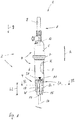
- Fig. 1
- zeigt in teilweise ab- und aufgeschnittener schematischer Seitenansicht eine Ausführungsform eines erfindungsgemäßen medizinischen Infusionsgeräts, das eine Ausführungsform einer erfindungsgemäßen Tropfkammeranordnung mit einer Stelleinrichtung aufweist,
- Fig. 2
- in vergrößerter schematischer Perspektivdarstellung einen Abschnitt der Stelleinrichtung,
- Fig. 3
- in schematischer Längsschnittdarstellung den Abschnitt der Stelleinrichtung nach
Fig. 2 , - Fig. 4, 5
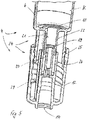
- die Tropfkammeranordnung nach
Fig. 1 im Bereich der Stelleinrichtung jeweils in abgeschnittener und leicht perspektivischer Längsschnittdarstellung in einem ersten Zustand (Fig. 4 ) und in einem zweiten Zustand (Fig. 5 ) und - Fig. 6, 7
- jeweils in schematischer Querschnittsdarstellung die Tropfkammeranordnung nach
Fig. 1 entlang einer Schnittlinie VI-VI gemäßFig. 1 im ersten Zustand (Fig. 6 ) und im zweiten Zustand (Fig. 7 ). - Gemäß
Fig. 1 ist ein medizinisches Infusionsgerät 1 zur Verwendung bei einer Infusionstherapie vorgesehen. Das medizinische Infusionsgerät 1 kann auch als Infusionssystem oder Überleitungssystem bezeichnet werden und dient einer schwerkraftgetriebenen Überleitung einer nicht näher bezeichneten medizinischen Flüssigkeit F von einem die Flüssigkeit beinhaltenden Infusionsbehälter in einen patientenseitigen Zugang. - Das Infusionsgerät 1 weist eine Tropfkammeranordnung 2 mit einem Tropfkammergehäuse 3 und einer Stelleinrichtung 4 auf.
- Das Tropfkammergehäuse 3 umgrenzt eine Tropfkammer K zur Aufnahme der Flüssigkeit F und ist vorliegend mehrteilig gestaltet, was jedoch nicht zwingend der Fall sein muss. Insoweit weist das Tropfkammergehäuse 3 vorliegend ein Tropfkammeroberteil 5 und ein Tropfkammerunterteil 6 auf. Das Tropfkammeroberteil 5 und das Tropfkammerunterteil 6 sind zur Ausbildung der Tropfkammer K stirnendseitig auf grundsätzlich bekannte Weise fluiddicht miteinander zusammengefügt. Zu diesem Zweck ist vorliegend eine Kunststoffumspritzung 7 vorgesehen, die zum einen eine fluiddichte Verbindung zwischen dem Tropfkammeroberteil 5 und dem Tropfkammerunterteil 6 gewährleistet und zum anderen einen nicht näher bezeichneten und in radialer Richtung der Tropfkammer K von dem Tropfkammergehäuse 3 im Übrigen abragenden Radialbund ausbildet.
- Die Tropfkammeranordnung 2 weist vorliegend zudem ein Einstechteil 8 auf. Das Einstechteil 8 ist in dem anhand
Fig. 1 ersichtlichen Zustand mit einer Abdeckkappe 9 versehen und dient einem Einstechen in einen hierfür vorgesehenen Abschnitt des besagten Infusionsbehälters. Das Einstechteil 8 weist eine grundsätzlich bekannte Gestaltung und Funktionsweise mit einem nicht näher ersichtlichen hohlen Einstechdorn auf, der zur Ableitung der Flüssigkeit aus dem Infusionsbehälter in diesen eingestochen wird. Hierdurch kann die Flüssigkeit aus dem Infusionsbehälter durch den Einstechdorn über einen Einlass 10 in die Tropfkammer K gelangen. - Die Stelleinrichtung 4 ist an einem dem Einstechteil 8 in Axialrichtung A der Tropfkammer K abgewandten Stirnendbereich des Tropfkammergehäuses 3 angeordnet. Die Stelleinrichtung 4 dient einer manuellen Einstellung einer aus einem Durchlass 11 der Tropfkammer K abzuleitenden Flussrate der Flüssigkeit F. Der insbesondere anhand
Fig. 4 ersichtliche Durchlass 11 ist an einem - in Bezug auf die Zeichenebene derFig. 1 - unteren Stirnendbereich des Tropfkammerunterteils 6 angeordnet und über die Tropfkammer K fluidleitend mit dem Einlass 10 verbunden. Die Stelleinrichtung 4 kann auch als Präzisionsflusssteller bezeichnet werden und gewährleistet, dass die Flüssigkeit F mit einer in medizinischer Hinsicht anforderungsgerechten Flussrate in den patientenseitigen Zugang verabreicht werden kann. - Die Stelleinrichtung 4 weist ein Betätigungselement 12 auf, das relativ zu dem Tropfkammergehäuse 3 zwischen unterschiedlichen Verlagerungspositionen (vgl.
Fig. 4 ,5 ) beweglich an dem Tropfkammergehäuse 3 gelagert ist. Das Betätigungselement 12 ist vorliegend auf noch näher beschriebene Weise dreh- bzw. schraubbeweglich an dem Tropfkammergehäuse 3 gelagert, was jedoch nicht zwingend ist. Stattdessen kann das Betätigungselement insbesondere in Form eines schwenkbeweglichen Schwenkelements oder eines linearverschieblichen Schiebeelements ausgebildet sein. - Die Stelleinrichtung 4 weist zudem einen Fluidkanal 13 auf, der anhand
Fig. 1 schematisch stark vereinfacht strichpunktiert angedeutet ist und einends fluidleitend mit dem Durchlass 11 verbunden ist. Andernends mündet der Fluidkanal 13 in einen Austritt 14 der Stelleinrichtung 4. Der Austritt 14 ist seinerseits fluidleitend mit einem Einlass 15 einer Schlauchleitung 16 verbunden. Die Schlauchleitung 16 ist Bestandteil des Infusionsgeräts 1 und trägt an einem der Stelleinrichtung 4 abgewandten Stirnende einen nicht näher bezeichneten Patientenkonnektor zur fluidleitenden Verbindung mit dem besagten patientenseitigen Zugang. - Der Fluidkanal 13 weist einen mit dem Betätigungselement 12 wirkverbundenen Strömungswiderstand W auf, der zur Einstellung der abzuleitenden Flussrate in Abhängigkeit der Verlagerungsposition des Betätigungselements 12 veränderlich ist.
- Der Strömungswiderstand ist eine Blende W, die einen in Abhängigkeit der Verlagerung des Betätigungselements 12 veränderlichen Querschnitt Q1, Q2 (vgl.
Fig. 6, 7 ) und eine unveränderliche Länge L1 (Fig. 4 ) aufweist. - Die Blende W ist vorliegend mittels eines Zusammenwirkens einer zylindrischen Mantelfläche 18 (vgl.
Fig. 2, 3 ) und eines zylindrischen Dichtabschnitts 19 (vgl.Fig. 4 ,5 ) gebildet. Die Mantelfläche 18 weist eine Nut 20 auf, die in Axialrichtung A über die Mantelfläche 18 erstreckt ist. Vorliegend ist die Nut 20 parallel zur Axialrichtung A orientiert und insoweit in Form einer Längs- oder Axialnut ausgebildet, was jedoch nicht zwingend ist. AnhandFig. 3 ist verdeutlicht, dass die Nut 20 einen in Längsrichtung der Nut 20 veränderlichen und nicht näher bezeichneten Nutquerschnitt aufweist. In der Längsschnittdarstellung derFig. 3 ist die Nut 20 zur besseren Verdeutlichung schwarz eingefärbt. Hierdurch ist ersichtlich, dass der Nutquerschnitt ausgehend von einem - in Bezug auf die Zeichenebene derFig. 3 - oberen Stirnendbereich der Nut 20 in Richtung eines unteren Stirnendbereichs kontinuierlich abnimmt. Mit anderen Worten ausgedrückt verringert sich eine in Radialrichtung R erstreckte Tiefe der Nut 20 in Axialrichtung A von oben nach unten, so dass die Nut 20 in Richtung des Durchlasses 11 (Fig. 4 ) einen maximalen Nutquerschnitt und in Richtung des Austritts 14 einen minimalen bzw. nicht vorhandenen Nutquerschnitt aufweist. - Der Dichtabschnitt 19 ist koaxial zu der Mantelfläche 18 orientiert (
Fig. 4 ) und kontaktiert die Mantelfläche 18 in Radialrichtung R fluiddicht. Der Dichtabschnitt 19 bildet somit eine Art ringförmiges Dichtelement bzw. eine ringförmige Dichtlippe, die auf einem Außenumfang der Mantelfläche 18 anliegt. Dabei übergreift der Dichtabschnitt 19 auch die Nut 20, wobei ein in Radialrichtung R unterhalb des Dichtabschnitts 19 in Axialrichtung A über die Länge L1 erstreckte, nicht näher bezeichnete Axialabschnitt der Nut 20 eine fluidleitende Verbindung zwischen dem Durchlass 11 und dem Austritt 14 bildet. Der in diesem Bereich strömungswirksame Nutquerschnitt des Axialabschnitts bildet den Querschnitt Q1, Q2 der Blende W. Zur Veränderung des strömungswirksamen Querschnitts Q1, Q2 der Blende W und damit zur Einstellung der Flussrate sind die Mantelfläche 18 und der Dichtabschnitt 19 in Abhängigkeit der Verlagerungsposition des Betätigungselements 12 zueinander axial relativbeweglich, was anhand derFig. 4 und5 gezeigt ist. - Der Dichtabschnitt 19 ist vorliegend an dem Tropfkammergehäuse 3 und insoweit feststehend ausgebildet. Demgegenüber ist die Mantelfläche 18 mit der Nut 20 mit dem Betätigungselement 12 wirkverbunden und mittels einer Drehbewegung des Betätigungselements 12 in Axialrichtung A relativ zu dem Dichtabschnitt 19 beweglich.
- Der Dichtabschnitt 19 ist vorliegend an einer Innenwandung 21 eines röhrenförmigen Röhrenfortsatzes 22 des Tropfkammergehäuses 3 angeordnet. Der Röhrenfortsatz 22 ist koaxial zu der Tropfkammer K erstreckt und unterseitig an dem Tropfkammerunterteil 6 ausgebildet. Der Dichtabschnitt 19 ragt in Radialrichtung R nach innen von der Innenwandung 21 ab und bildet insoweit eine Verengung eines nicht näher bezeichneten durch den röhrenförmigen Röhrenfortsatz 22 erstreckten Lumens.
- Die Mantelfläche 18 mit der Nut 20 ist vorliegend an einem Stellzylinder 23 ausgebildet, der mechanisch mit dem Betätigungselement 12 wirkverbunden ist. Vorliegend ist das Betätigungselement 12 gemeinsam mit dem Stellzylinder 23 einstückig in Form eines Kunststoffspritzgussteils gefertigt, was jedoch nicht zwingend ist.
- Der Stellzylinder 23 ist in Axialrichtung A in den Röhrenfortsatz 22 eingeführt, so dass der Dichtabschnitt 19 in Radialrichtung R auf dem Stellzylinder 23 bzw. dessen Mantelfläche 18 aufliegt.
- Vorliegend weist die Stelleinrichtung 4 zur Wandlung einer rotatorischen Betätigungsbewegung des Betätigungselements 12 in die axiale Stellbewegung des Stellzylinders 23 ein Stellgetriebe in Form eines Schraubgetriebes 24 auf. Das Schraubgetriebe 24 weist einen am Tropfkammergehäuse 3 angeordneten Gewindeabschnitt 25 und einen am Betätigungselement 12 angeordneten komplementären Gegengewindeabschnitt 26 auf. Der Gewindeabschnitt 25 trägt vorliegend ein nicht näher bezeichnetes Außengewinde. Dementsprechend trägt der Gegengewindeabschnitt 26 ein hierzu komplementäres Innengewinde. Der Gewindeabschnitt 25 und der Gegengewindeabschnitt 26 sind koaxial zu der Tropfkammer K und somit auch koaxial zu dem Stellzylinder 23 und dem Dichtabschnitt 19 orientiert.
- Zudem weist die Stelleinrichtung 4 vorliegend eine Anzeigeeinrichtung 27, 28 zur Anzeige einer mittels der Stelleinrichtung 4 eingestellten Flussrate der Flüssigkeit F auf. Die Anzeigeeinrichtung 27, 28 weist eine Skale 27, die aus einer Abfolge zueinander benachbart angeordneter Ziffern gebildet ist, und ein Zeigerelement 28 auf. Die Skale 27 ist vorliegend an einem nicht näher bezeichneten Außenumfang des Betätigungselements 12 angeordnet. Das Zeigerelement 28 ist vorliegend dreieckig ausgebildet und an einem an die Skale 27 angrenzenden Abschnitt des Tropfkammergehäuses 3 angeordnet. Je nach Verlagerungsposition des Betätigungselements 12 zeigt das Zeigerelement 28 auf einen unterschiedlichen Bereich der Skale 27, so dass hierdurch eine entsprechende Flussrate für eine Bedienperson ablesbar ist.
- Nachfolgend wird die Funktionsweise der Stelleinrichtung 4 bei einer Überleitung der Flüssigkeit mittels des Infusionsgeräts 1 näher beschrieben. Hierbei wird von der anhand
Fig. 1 ersichtlichen Konfiguration des Infusionsgeräts 1 ausgegangen, in der die Axialrichtung A parallel zu einem Erdschwerevektor g orientiert ist. - Zusätzlich wird abweichend von der Darstellung der
Fig. 1 davon ausgegangen, dass das Einstechteil 8 auf die vorbeschriebene Weise in den Infusionsbehälter eingestochen ist, so dass die Flüssigkeit F schwerkraftbedingt aus dem Infusionsbehälter über das Einstechteil 8 durch den Einlass 10 in die Tropfkammer K gelangen kann. - In der anhand
Fig. 1 ersichtlichen Konfiguration nimmt das Betätigungselement 12 eine anhandFig. 4 näher dargestellte Verlagerungsposition ein. In dieser ist das Betätigungselement 12 in Axialrichtung A weitestmöglich auf das Tropfkammergehäuse 3 aufgeschraubt. Dementsprechend kontaktiert der Dichtabschnitt 19 den Stellzylinder 23 in einem unteren Bereich der Nut 20. In diesem Bereich ist der Nutquerschnitt der Nut 20 minimal bzw. eine Nuttiefe ist nicht vorhanden (vgl.Fig. 3 ), so dass der Durchlass 11 fluiddicht verschlossen ist. - Zur fluidleitenden Freigabe des Durchlasses 11 und zur Einstellung der aus der Tropfkammer K abzuleitenden Flussrate der Flüssigkeit F wird das Betätigungselement 12 um seine Längsachse drehbeweglich betätigt und hierbei durch ein Zusammenwirken des Gewindeabschnitts 25 und des Gegengewindeabschnitts 26 in Axialrichtung A von dem Tropfkammergehäuse 3 hinwegbewegt. Hierdurch bewegt sich der Stellzylinder 23 in Axialrichtung A - und gleichzeitig zudem um die Längsachse des Betätigungselements 12 - relativ zu dem Dichtabschnitt 19. Je nach Verlagerungsposition des Betätigungselements 12 bzw. Stellposition des Stellzylinders 23 wird hierdurch ein anderer Axialabschnitt der Nut 20 unter den Dichtabschnitt 19 verlagert. Aufgrund des in Längsrichtung der Nut 20 veränderlichen Nutquerschnitts ändert sich hierbei der strömungswirksame Querschnitt Q1, Q2 der Blende W und somit der Strömungswiderstand des Fluidkanals 13 (vgl.
Fig. 6, 7 ). In der anhandFig. 5 ersichtlichen Konfiguration ist das Betätigungselement 12 in eine nicht näher bezeichnete Endlage verlagert, in der der Stellzylinder 23 außer Eingriff mit dem Dichtabschnitt 19 gerät. Hierdurch ist ein nicht näher bezeichneter Ringspalt zwischen dem Dichtabschnitt 19 und einem stirnendseitigen Bereich des Stellzylinders 23 gebildet. - In einer zeichnerisch nicht dargestellten Zwischenstellung zwischen den anhand
Fig. 4 und5 ersichtlichen Konfigurationen kann die Flüssigkeit F dementsprechend über den Durchlass 11 in eine radial zwischen dem Röhrenfortsatz 22 und dem Stellzylinder 23 gebildeten Ringspalt und von diesem durch den strömungswirksamen Nutquerschnitt der Nut 20 im Bereich des Dichtabschnitts 19 in einen weiteren Durchlass 29 der Stelleinrichtung 4 und von dort in den Austritt 14 gelangen. - Anhand
Fig. 4 ist ersichtlich, dass die Länge L1 der Blende W deutlich geringer ist als eine Länge L2 des Fluidkanals 13. Vorliegend beträgt die Länge L1 lediglich in etwa 1 % der Länge L2, so dass die Blende W stark lokal begrenzt in dem Fluidkanal 13 wirkt. Es versteht sich, dass auch ein hiervon abweichendes Verhältnis zwischen den Längen L1 und L2 vorgesehen sein kann.
Claims (9)
- Tropfkammeranordnung (2) für ein medizinisches Infusionsgerät (1) zur schwerkraftbetriebenen Überleitung einer Flüssigkeit (F) bei einer Infusionstherapie, aufweisend- ein Tropfkammergehäuse (3), das eine Tropfkammer (K) zur Aufnahme der Flüssigkeit (F) umgrenzt und einen Einlass (10) zur Einleitung der Flüssigkeit in die Tropfkammer (K) und einen Durchlass (11) zur Ableitung der Flüssigkeit (F) aus der Tropfkammer (K) aufweist,- und eine Stelleinrichtung (4), die eine manuelle Einstellung einer aus dem Durchlass (11) der Tropfkammer (K) abzuleitenden Flussrate der Flüssigkeit (F) gestattet,- wobei die Stelleinrichtung (4) ein Betätigungselement (12), das relativ zu dem Tropfkammergehäuse (3) zwischen unterschiedlichen Verlagerungspositionen beweglich an dem Tropfkammergehäuse (3) gelagert ist, und einen einends fluidleitend mit dem Durchlass (11) verbundenen und andernends in einen Austritt (14) der Stelleinrichtung (4) mündenden Fluidkanal (13) mit einem Strömungswiderstand (W) aufweist,- und wobei der Strömungswiderstand (W) mit dem Betätigungselement (12) wirkverbunden und zur Einstellung der abzuleitenden Flussrate in Abhängigkeit der Verlagerungsposition des Betätigungselements (12) veränderlich ist,- dadurch gekennzeichnet, dass der Strömungswiderstand eine Blende (W) ist, die einen in Abhängigkeit der Verlagerungsposition des Betätigungselements (12) veränderlichen Querschnitt (Q1, Q2) und eine unveränderliche Länge (L1) aufweist.
- Tropfkammeranordnung (2) nach Anspruch 1, dadurch gekennzeichnet, dass die Länge (L1) der Blende (W) maximal 10 %, bevorzugt maximal 5 %, besonders bevorzugt maximal 1 %, einer Länge (L2) des Fluidkanals (13) beträgt.
- Tropfkammeranordnung (2) nach Anspruch 1 oder 2, dadurch gekennzeichnet, dass die Blende (W) mittels eines Zusammenwirkens einer zylindrischen Mantelfläche (18) und eines zylindrischen Dichtabschnitts (19) gebildet ist, wobei die Mantelfläche (18) eine axial erstreckte Nut (20) mit einem in Längsrichtung der Nut (20) veränderlichen Nutquerschnitt aufweist, wobei der Dichtabschnitt (19) koaxial zu der Mantelfläche (18) orientiert ist und dieselbe radial kontaktierend in Umfangsrichtung umgreift, wobei ein an den Dichtabschnitt (19) angrenzender strömungswirksamer Nutquerschnitt den Querschnitt (Q1, Q2) der Blende (W) bildet, und wobei die Mantelfläche (18) und der Dichtabschnitt (19) zur Veränderung des Querschnitts (Q1, Q2) der Blende (W) in Abhängigkeit der Verlagerungsposition des Betätigungselements (12) zueinander axial relativbeweglich sind.
- Tropfkammeranordnung (2) nach Anspruch 3, dadurch gekennzeichnet, dass der Dichtabschnitt (19) an dem Tropfkammergehäuse (3) ausgebildet ist, und dass die Mantelfläche (18) an einem Stellzylinder (23) ausgebildet ist, der dem Betätigungselement (12) zugeordnet ist.
- Tropfkammeranordnung (2) nach Anspruch 3 oder 4, dadurch gekennzeichnet, dass der Dichtabschnitt (19) an einer Innenwandung (21) eines röhrenförmigen Röhrenfortsatzes (22) des Tropfkammergehäuses (3) angeordnet ist, wobei der Stellzylinder (23) koaxial in den Röhrenfortsatz (22) eingeführt ist.
- Tropfkammeranordnung (2) nach einem der Ansprüche 3 bis 5, dadurch gekennzeichnet, dass die Stelleinrichtung (4) ein Stellgetriebe (24) aufweist, mittels dessen eine rotatorische Bewegung des Betätigungselements (12) in eine axiale Bewegung der Mantelfläche (18) und/oder des Stellzylinders (23) gegenüber dem Dichtabschnitt (19) wandelbar ist.
- Tropfkammeranordnung (2) nach Anspruch 6, dadurch gekennzeichnet, dass das Stellgetriebe ein Schraubgetriebe (24) ist, das einen an dem Tropfkammergehäuse (3) angeordneten Gewindeabschnitt (25) und einen an dem Betätigungselement (12) angeordneten Gegengewindeabschnitt (26) aufweist.
- Tropfkammeranordnung (2) nach einem der vorhergehenden Ansprüche, dadurch gekennzeichnet, dass die Stelleinrichtung (4) eine zur Anzeige einer eingestellten Flussrate eingerichtete Anzeigeeinrichtung (27, 28) mit einer Skale (27) und einem Zeigerelement (28) aufweist.
- Medizinisches Infusionsgerät (1) zur schwerkraftgetriebenen Überleitung einer Flüssigkeit (F) bei einer Infusionstherapie, gekennzeichnet durch eine Tropfkammeranordnung (2) nach einem der vorhergehenden Ansprüche.
Applications Claiming Priority (1)
| Application Number | Priority Date | Filing Date | Title |
|---|---|---|---|
| DE102019203846.8A DE102019203846A1 (de) | 2019-03-21 | 2019-03-21 | Tropfkammeranordnung für ein medizinisches Infusionsgerät |
Publications (2)
| Publication Number | Publication Date |
|---|---|
| EP3711792A1 true EP3711792A1 (de) | 2020-09-23 |
| EP3711792B1 EP3711792B1 (de) | 2025-09-03 |
Family
ID=69941225
Family Applications (1)
| Application Number | Title | Priority Date | Filing Date |
|---|---|---|---|
| EP20164528.0A Active EP3711792B1 (de) | 2019-03-21 | 2020-03-20 | Tropfkammeranordnung für ein medizinisches infusionsgerät |
Country Status (2)
| Country | Link |
|---|---|
| EP (1) | EP3711792B1 (de) |
| DE (1) | DE102019203846A1 (de) |
Cited By (4)
| Publication number | Priority date | Publication date | Assignee | Title |
|---|---|---|---|---|
| WO2022169800A1 (en) * | 2021-02-02 | 2022-08-11 | PAVmed Inc. | System and method for providing an adjustable flow rate |
| US11668404B2 (en) | 2019-04-10 | 2023-06-06 | PAVmed Inc. | Systems and methods for a variable flow resistor |
| US12220568B2 (en) | 2021-02-04 | 2025-02-11 | PAVmed Inc. | Systems and methods for priming a fluid line |
| WO2025043978A1 (zh) * | 2023-08-29 | 2025-03-06 | 江西洪达医疗器械集团有限公司 | 一种多功能输液器 |
Families Citing this family (1)
| Publication number | Priority date | Publication date | Assignee | Title |
|---|---|---|---|---|
| DE102022205578A1 (de) | 2022-06-01 | 2023-12-07 | B. Braun Melsungen Aktiengesellschaft | Medizinische Fluidsteuervorrichtung |
Citations (7)
| Publication number | Priority date | Publication date | Assignee | Title |
|---|---|---|---|---|
| FR2148395A2 (de) * | 1970-09-09 | 1973-03-23 | Party Max | |
| DE2452117A1 (de) * | 1974-11-02 | 1976-05-13 | Lothar Engel | Tropfeinsteller (durchflussregler) fuer infusionen und transfusionen |
| GB1554629A (en) * | 1977-05-06 | 1979-10-24 | Yarden Medical Eng Ltd | Valve for adjusting the flow of a liquid under gravity |
| US4361147A (en) * | 1979-01-22 | 1982-11-30 | Master Medical Corporation | Flow control device for administration of intravenous fluids |
| US6213986B1 (en) * | 1995-09-29 | 2001-04-10 | Appro Healthcare, Inc. | Liquid flow rate control device |
| US20110125103A1 (en) * | 2009-11-25 | 2011-05-26 | Baxter International Inc. | Drip chamber with flow control |
| DE202017002518U1 (de) | 2017-05-04 | 2017-07-04 | B. Braun Melsungen Ag | Tropfkammeranordnung für ein medizinisches Infusionssystem |
-
2019
- 2019-03-21 DE DE102019203846.8A patent/DE102019203846A1/de not_active Ceased
-
2020
- 2020-03-20 EP EP20164528.0A patent/EP3711792B1/de active Active
Patent Citations (7)
| Publication number | Priority date | Publication date | Assignee | Title |
|---|---|---|---|---|
| FR2148395A2 (de) * | 1970-09-09 | 1973-03-23 | Party Max | |
| DE2452117A1 (de) * | 1974-11-02 | 1976-05-13 | Lothar Engel | Tropfeinsteller (durchflussregler) fuer infusionen und transfusionen |
| GB1554629A (en) * | 1977-05-06 | 1979-10-24 | Yarden Medical Eng Ltd | Valve for adjusting the flow of a liquid under gravity |
| US4361147A (en) * | 1979-01-22 | 1982-11-30 | Master Medical Corporation | Flow control device for administration of intravenous fluids |
| US6213986B1 (en) * | 1995-09-29 | 2001-04-10 | Appro Healthcare, Inc. | Liquid flow rate control device |
| US20110125103A1 (en) * | 2009-11-25 | 2011-05-26 | Baxter International Inc. | Drip chamber with flow control |
| DE202017002518U1 (de) | 2017-05-04 | 2017-07-04 | B. Braun Melsungen Ag | Tropfkammeranordnung für ein medizinisches Infusionssystem |
Cited By (4)
| Publication number | Priority date | Publication date | Assignee | Title |
|---|---|---|---|---|
| US11668404B2 (en) | 2019-04-10 | 2023-06-06 | PAVmed Inc. | Systems and methods for a variable flow resistor |
| WO2022169800A1 (en) * | 2021-02-02 | 2022-08-11 | PAVmed Inc. | System and method for providing an adjustable flow rate |
| US12220568B2 (en) | 2021-02-04 | 2025-02-11 | PAVmed Inc. | Systems and methods for priming a fluid line |
| WO2025043978A1 (zh) * | 2023-08-29 | 2025-03-06 | 江西洪达医疗器械集团有限公司 | 一种多功能输液器 |
Also Published As
| Publication number | Publication date |
|---|---|
| EP3711792B1 (de) | 2025-09-03 |
| DE102019203846A1 (de) | 2020-09-24 |
Similar Documents
| Publication | Publication Date | Title |
|---|---|---|
| EP3711792B1 (de) | Tropfkammeranordnung für ein medizinisches infusionsgerät | |
| EP3102254B1 (de) | Injektionsgerät | |
| DE3146541C2 (de) | ||
| EP2804504B1 (de) | Medienspender | |
| EP3274045B1 (de) | Medizinische fluidsteuervorrichtung für ein medizinisches fluidleitungssystem | |
| EP3355965B1 (de) | Autoinjektor mit dosiervorrichtung | |
| DE202013001350U1 (de) | Injektionsgerät | |
| EP2812054B1 (de) | Injektionsgerät | |
| EP3618891B1 (de) | Tropfkammeranordnung für ein medizinisches infusionssystem | |
| EP3268544B1 (de) | Sanitäres umschaltventil sowie baugruppe mit einem solchen umschaltventil | |
| DE2631752C3 (de) | Schwenkende Berieselungsvorrichtung | |
| DE202014001135U1 (de) | Injektionsgerät | |
| DE2622096B2 (de) | Ventil für ein Gasfeuerzeug | |
| EP2805089B1 (de) | Sanitärarmatur | |
| EP0444523A2 (de) | Ventilpistole für ein Hochdruckreinigungsgerät sowie Schlauchkupplung, insbesondere für eine solche Ventilpistole | |
| WO2016120163A1 (de) | Hohlnadel-baugruppe | |
| EP1884157A1 (de) | Bewässerungsvorrichtung | |
| DE102023116174A1 (de) | Vorrichtung zum Auftragen eines mehrkomponentigen viskosen Materials auf Werkstücke | |
| DE2050025B2 (de) | Eingriff Mischbatterie | |
| DE102019211863A1 (de) | Stelleinrichtung zur Einstellung einer Flussrate einer medizinischen Elastomerpumpe | |
| EP3321435B1 (de) | Ablaufgarnituranordnung | |
| DE4312015A1 (de) | Vorrichtung zum Dosieren und Abfüllen von dickflüssigen oder pastösen Produkten, insbesondere Nahrungsmittel, vornehmlich Margarine oder dergleichen | |
| DE4002089C2 (de) | ||
| DE102019208115A1 (de) | Tropfkammeranordnung für ein medizinisches Infusionsgerät | |
| DE10234930A1 (de) | Flüssigkeitsdispenser, Ausgabekanülen-Baukastensystem hierfür und Ausgabekanüle |
Legal Events
| Date | Code | Title | Description |
|---|---|---|---|
| PUAI | Public reference made under article 153(3) epc to a published international application that has entered the european phase |
Free format text: ORIGINAL CODE: 0009012 |
|
| STAA | Information on the status of an ep patent application or granted ep patent |
Free format text: STATUS: THE APPLICATION HAS BEEN PUBLISHED |
|
| AK | Designated contracting states |
Kind code of ref document: A1 Designated state(s): AL AT BE BG CH CY CZ DE DK EE ES FI FR GB GR HR HU IE IS IT LI LT LU LV MC MK MT NL NO PL PT RO RS SE SI SK SM TR |
|
| AX | Request for extension of the european patent |
Extension state: BA ME |
|
| RIN1 | Information on inventor provided before grant (corrected) |
Inventor name: CONRAD, CHRISTOPH Inventor name: GRUNDEI, INGO Inventor name: SEIDEL, GERRIT Inventor name: FUCHS, JUERGEN |
|
| STAA | Information on the status of an ep patent application or granted ep patent |
Free format text: STATUS: REQUEST FOR EXAMINATION WAS MADE |
|
| 17P | Request for examination filed |
Effective date: 20210301 |
|
| RBV | Designated contracting states (corrected) |
Designated state(s): AL AT BE BG CH CY CZ DE DK EE ES FI FR GB GR HR HU IE IS IT LI LT LU LV MC MK MT NL NO PL PT RO RS SE SI SK SM TR |
|
| RIN1 | Information on inventor provided before grant (corrected) |
Inventor name: GRUNDEI, INGO Inventor name: FUCHS, JUERGEN Inventor name: SEIDEL, GERRIT Inventor name: CONRAD, CHRISTOPH |
|
| GRAP | Despatch of communication of intention to grant a patent |
Free format text: ORIGINAL CODE: EPIDOSNIGR1 |
|
| STAA | Information on the status of an ep patent application or granted ep patent |
Free format text: STATUS: GRANT OF PATENT IS INTENDED |
|
| INTG | Intention to grant announced |
Effective date: 20250407 |
|
| GRAS | Grant fee paid |
Free format text: ORIGINAL CODE: EPIDOSNIGR3 |
|
| GRAA | (expected) grant |
Free format text: ORIGINAL CODE: 0009210 |
|
| STAA | Information on the status of an ep patent application or granted ep patent |
Free format text: STATUS: THE PATENT HAS BEEN GRANTED |
|
| AK | Designated contracting states |
Kind code of ref document: B1 Designated state(s): AL AT BE BG CH CY CZ DE DK EE ES FI FR GB GR HR HU IE IS IT LI LT LU LV MC MK MT NL NO PL PT RO RS SE SI SK SM TR |
|
| REG | Reference to a national code |
Ref country code: CH Ref legal event code: EP |
|
| REG | Reference to a national code |
Ref country code: DE Ref legal event code: R096 Ref document number: 502020011781 Country of ref document: DE |
|
| REG | Reference to a national code |
Ref country code: IE Ref legal event code: FG4D Free format text: LANGUAGE OF EP DOCUMENT: GERMAN |
|
| REG | Reference to a national code |
Ref country code: NL Ref legal event code: MP Effective date: 20250903 |
|
| PG25 | Lapsed in a contracting state [announced via postgrant information from national office to epo] |
Ref country code: NO Free format text: LAPSE BECAUSE OF FAILURE TO SUBMIT A TRANSLATION OF THE DESCRIPTION OR TO PAY THE FEE WITHIN THE PRESCRIBED TIME-LIMIT Effective date: 20251203 |
|
| REG | Reference to a national code |
Ref country code: LT Ref legal event code: MG9D |
|
| PG25 | Lapsed in a contracting state [announced via postgrant information from national office to epo] |
Ref country code: FI Free format text: LAPSE BECAUSE OF FAILURE TO SUBMIT A TRANSLATION OF THE DESCRIPTION OR TO PAY THE FEE WITHIN THE PRESCRIBED TIME-LIMIT Effective date: 20250903 |
|
| PG25 | Lapsed in a contracting state [announced via postgrant information from national office to epo] |
Ref country code: HR Free format text: LAPSE BECAUSE OF FAILURE TO SUBMIT A TRANSLATION OF THE DESCRIPTION OR TO PAY THE FEE WITHIN THE PRESCRIBED TIME-LIMIT Effective date: 20250903 |
|
| PG25 | Lapsed in a contracting state [announced via postgrant information from national office to epo] |
Ref country code: GR Free format text: LAPSE BECAUSE OF FAILURE TO SUBMIT A TRANSLATION OF THE DESCRIPTION OR TO PAY THE FEE WITHIN THE PRESCRIBED TIME-LIMIT Effective date: 20251204 |
|
| PG25 | Lapsed in a contracting state [announced via postgrant information from national office to epo] |
Ref country code: SE Free format text: LAPSE BECAUSE OF FAILURE TO SUBMIT A TRANSLATION OF THE DESCRIPTION OR TO PAY THE FEE WITHIN THE PRESCRIBED TIME-LIMIT Effective date: 20250903 |
|
| PG25 | Lapsed in a contracting state [announced via postgrant information from national office to epo] |
Ref country code: LV Free format text: LAPSE BECAUSE OF FAILURE TO SUBMIT A TRANSLATION OF THE DESCRIPTION OR TO PAY THE FEE WITHIN THE PRESCRIBED TIME-LIMIT Effective date: 20250903 |
|
| PG25 | Lapsed in a contracting state [announced via postgrant information from national office to epo] |
Ref country code: PL Free format text: LAPSE BECAUSE OF FAILURE TO SUBMIT A TRANSLATION OF THE DESCRIPTION OR TO PAY THE FEE WITHIN THE PRESCRIBED TIME-LIMIT Effective date: 20250903 Ref country code: BG Free format text: LAPSE BECAUSE OF FAILURE TO SUBMIT A TRANSLATION OF THE DESCRIPTION OR TO PAY THE FEE WITHIN THE PRESCRIBED TIME-LIMIT Effective date: 20250903 |
|
| PG25 | Lapsed in a contracting state [announced via postgrant information from national office to epo] |
Ref country code: RS Free format text: LAPSE BECAUSE OF FAILURE TO SUBMIT A TRANSLATION OF THE DESCRIPTION OR TO PAY THE FEE WITHIN THE PRESCRIBED TIME-LIMIT Effective date: 20251203 |
|
| PG25 | Lapsed in a contracting state [announced via postgrant information from national office to epo] |
Ref country code: ES Free format text: LAPSE BECAUSE OF FAILURE TO SUBMIT A TRANSLATION OF THE DESCRIPTION OR TO PAY THE FEE WITHIN THE PRESCRIBED TIME-LIMIT Effective date: 20250903 |
|
| PG25 | Lapsed in a contracting state [announced via postgrant information from national office to epo] |
Ref country code: NL Free format text: LAPSE BECAUSE OF FAILURE TO SUBMIT A TRANSLATION OF THE DESCRIPTION OR TO PAY THE FEE WITHIN THE PRESCRIBED TIME-LIMIT Effective date: 20250903 |
|
| PG25 | Lapsed in a contracting state [announced via postgrant information from national office to epo] |
Ref country code: SM Free format text: LAPSE BECAUSE OF FAILURE TO SUBMIT A TRANSLATION OF THE DESCRIPTION OR TO PAY THE FEE WITHIN THE PRESCRIBED TIME-LIMIT Effective date: 20250903 |
|
| PGFP | Annual fee paid to national office [announced via postgrant information from national office to epo] |
Ref country code: GB Payment date: 20260324 Year of fee payment: 7 |
|
| PGFP | Annual fee paid to national office [announced via postgrant information from national office to epo] |
Ref country code: DE Payment date: 20260320 Year of fee payment: 7 |
|
| PG25 | Lapsed in a contracting state [announced via postgrant information from national office to epo] |
Ref country code: IT Free format text: LAPSE BECAUSE OF FAILURE TO SUBMIT A TRANSLATION OF THE DESCRIPTION OR TO PAY THE FEE WITHIN THE PRESCRIBED TIME-LIMIT Effective date: 20250903 |
|
| PG25 | Lapsed in a contracting state [announced via postgrant information from national office to epo] |
Ref country code: IS Free format text: LAPSE BECAUSE OF FAILURE TO SUBMIT A TRANSLATION OF THE DESCRIPTION OR TO PAY THE FEE WITHIN THE PRESCRIBED TIME-LIMIT Effective date: 20260103 |
|
| PGFP | Annual fee paid to national office [announced via postgrant information from national office to epo] |
Ref country code: FR Payment date: 20260324 Year of fee payment: 7 |
|
| PG25 | Lapsed in a contracting state [announced via postgrant information from national office to epo] |
Ref country code: PT Free format text: LAPSE BECAUSE OF FAILURE TO SUBMIT A TRANSLATION OF THE DESCRIPTION OR TO PAY THE FEE WITHIN THE PRESCRIBED TIME-LIMIT Effective date: 20260105 Ref country code: CZ Free format text: LAPSE BECAUSE OF FAILURE TO SUBMIT A TRANSLATION OF THE DESCRIPTION OR TO PAY THE FEE WITHIN THE PRESCRIBED TIME-LIMIT Effective date: 20250903 |
|
| PG25 | Lapsed in a contracting state [announced via postgrant information from national office to epo] |
Ref country code: SK Free format text: LAPSE BECAUSE OF FAILURE TO SUBMIT A TRANSLATION OF THE DESCRIPTION OR TO PAY THE FEE WITHIN THE PRESCRIBED TIME-LIMIT Effective date: 20250903 Ref country code: EE Free format text: LAPSE BECAUSE OF FAILURE TO SUBMIT A TRANSLATION OF THE DESCRIPTION OR TO PAY THE FEE WITHIN THE PRESCRIBED TIME-LIMIT Effective date: 20250903 |
|
| REG | Reference to a national code |
Ref country code: DE Ref legal event code: R097 Ref document number: 502020011781 Country of ref document: DE |
|
| PG25 | Lapsed in a contracting state [announced via postgrant information from national office to epo] |
Ref country code: LT Free format text: LAPSE BECAUSE OF FAILURE TO SUBMIT A TRANSLATION OF THE DESCRIPTION OR TO PAY THE FEE WITHIN THE PRESCRIBED TIME-LIMIT Effective date: 20250903 |
|
| PG25 | Lapsed in a contracting state [announced via postgrant information from national office to epo] |
Ref country code: DK Free format text: LAPSE BECAUSE OF FAILURE TO SUBMIT A TRANSLATION OF THE DESCRIPTION OR TO PAY THE FEE WITHIN THE PRESCRIBED TIME-LIMIT Effective date: 20250903 |
|
| PLBE | No opposition filed within time limit |
Free format text: ORIGINAL CODE: 0009261 |
|
| STAA | Information on the status of an ep patent application or granted ep patent |
Free format text: STATUS: NO OPPOSITION FILED WITHIN TIME LIMIT |
|
| REG | Reference to a national code |
Ref country code: CH Ref legal event code: L10 Free format text: ST27 STATUS EVENT CODE: U-0-0-L10-L00 (AS PROVIDED BY THE NATIONAL OFFICE) Effective date: 20260715 |
|
| 26N | No opposition filed |
Effective date: 20260604 |