EP3711552B1 - Smoking substitute system - Google Patents
Smoking substitute system Download PDFInfo
- Publication number
- EP3711552B1 EP3711552B1 EP19020184.8A EP19020184A EP3711552B1 EP 3711552 B1 EP3711552 B1 EP 3711552B1 EP 19020184 A EP19020184 A EP 19020184A EP 3711552 B1 EP3711552 B1 EP 3711552B1
- Authority
- EP
- European Patent Office
- Prior art keywords
- heater
- aerosol
- tobacco
- controller
- consumable
- Prior art date
- Legal status (The legal status is an assumption and is not a legal conclusion. Google has not performed a legal analysis and makes no representation as to the accuracy of the status listed.)
- Active
Links
Images


Classifications
-
- A—HUMAN NECESSITIES
- A24—TOBACCO; CIGARS; CIGARETTES; SIMULATED SMOKING DEVICES; SMOKERS' REQUISITES
- A24F—SMOKERS' REQUISITES; MATCH BOXES; SIMULATED SMOKING DEVICES
- A24F40/00—Electrically operated smoking devices; Component parts thereof; Manufacture thereof; Maintenance or testing thereof; Charging means specially adapted therefor
- A24F40/50—Control or monitoring
-
- A—HUMAN NECESSITIES
- A24—TOBACCO; CIGARS; CIGARETTES; SIMULATED SMOKING DEVICES; SMOKERS' REQUISITES
- A24F—SMOKERS' REQUISITES; MATCH BOXES; SIMULATED SMOKING DEVICES
- A24F40/00—Electrically operated smoking devices; Component parts thereof; Manufacture thereof; Maintenance or testing thereof; Charging means specially adapted therefor
- A24F40/60—Devices with integrated user interfaces
-
- A—HUMAN NECESSITIES
- A24—TOBACCO; CIGARS; CIGARETTES; SIMULATED SMOKING DEVICES; SMOKERS' REQUISITES
- A24F—SMOKERS' REQUISITES; MATCH BOXES; SIMULATED SMOKING DEVICES
- A24F40/00—Electrically operated smoking devices; Component parts thereof; Manufacture thereof; Maintenance or testing thereof; Charging means specially adapted therefor
- A24F40/20—Devices using solid inhalable precursors
Definitions
- the present invention relates to a smoking substitute system and particularly, although not exclusively, to a smoking substitute device and a method of controlling operation of the smoking substitute device.
- the smoking of tobacco is generally considered to expose a smoker to potentially harmful substances. It is generally thought that a significant amount of the potentially harmful substances are generated through the heat caused by the burning and/or combustion of the tobacco and the constituents of the burnt tobacco in the tobacco smoke itself.
- Conventional combustible smoking articles such as cigarettes, typically comprise a cylindrical rod of tobacco comprising shreds of tobacco which is surrounded by a wrapper, and usually also a cylindrical filter axially aligned in an abutting relationship with the wrapped tobacco rod.
- the filter typically comprises a filtration material which is circumscribed by a plug wrap.
- the wrapped tobacco rod and the filter are joined together by a wrapped band of tipping paper that circumscribes the entire length of the filter and an adjacent portion of the wrapped tobacco rod.
- a conventional cigarette of this type is used by lighting the end opposite to the filter, and burning the tobacco rod. The smoker receives mainstream smoke into their mouth by drawing on the mouth end or filter end of the cigarette.
- Such smoking substitute systems can form part of nicotine replacement therapies aimed at people who wish to stop smoking and overcome a dependence on nicotine.
- Smoking substitute systems include electronic systems that permit a user to simulate the act of smoking by producing an aerosol (also referred to as a "vapour") that is drawn into the lungs through the mouth (inhaled) and then exhaled.
- aerosol also referred to as a "vapour”
- the inhaled aerosol typically bears nicotine and/or flavourings without, or with fewer of, the odour and health risks associated with traditional smoking.
- smoking substitute systems are intended to provide a substitute for the rituals of smoking, whilst providing the user with a similar experience and satisfaction to those experienced with traditional smoking and with combustible tobacco products.
- Some smoking substitute systems use smoking substitute articles (also referred to as a "consumables”) that are designed to resemble a traditional cigarette and are cylindrical in form with a mouthpiece at one end.
- HT Heated Tobacco
- HNB Heat not burn
- the tobacco may be leaf tobacco or reconstituted tobacco.
- the vapour may contain nicotine and/or flavourings.
- the intention is that the tobacco is heated but not burned, i.e. the tobacco does not undergo combustion.
- a typical HT smoking substitute system may include a device and a consumable.
- the consumable may include the tobacco material.
- the device and consumable may be configured to be physically coupled together.
- heat may be imparted to the tobacco material by a heating element of the device, wherein airflow through the tobacco material causes components in the tobacco material to be released as vapour.
- a vapour may also be formed from a carrier in the tobacco material (this carrier may for example include propylene glycol and/or vegetable glycerine) and additionally volatile compounds released from the tobacco.
- the released vapour may be entrained in the airflow drawn through the tobacco.
- the vapour passes through the consumable (entrained in the airflow) from the location of vaporisation to an outlet of the consumable (e.g. a mouthpiece), the vapour cools and condenses to form an aerosol for inhalation by the user.
- the aerosol will normally contain the volatile compounds.
- HT smoking substitute systems heating as opposed to burning the tobacco material is believed to cause fewer, or smaller quantities, of the more harmful compounds ordinarily produced during smoking. Consequently, the HT approach may reduce the odour and/or health risks that can arise through the burning, combustion and pyrolytic degradation of tobacco.
- WO 2015/177304 A discloses an electrically heated aerosol-generating system with end heater.
- US 2015/020825 A discloses an electronic smoking article with haptic feedback.
- US 2019/021400 A discloses a vaporisation device, method of using the device, a charging case, a kit, and a vibration assembly.
- US 2015/257445 A discloses an aerosol delivery device and related method and computer program product for controlling an aerosol delivery device based on input characteristics.
- US 2017/238617 A discloses an electronic vaporiser.
- US 2018/132529 A discloses an aerosol delivery device with integrated wireless connectivity for temperature monitoring
- the present invention relates to operating a smoking substitute system to provide haptic feedback indicating different operating modes of a smoking substitute device.
- a method of providing operating a heated tobacco device comprising: selecting a first operational mode or a second operational mode from at least two operational modes; when the first operational mode is selected, supplying power to a heater of the device to increase the temperature of the heater to a first target temperature; providing a first haptic feedback output in response to a current temperature of the heater reaching the first target temperature; when the second operational mode is selected, supplying power to the heater to increase the temperature of the heater to a second, different, target temperature; providing a second, different, haptic feedback output in response to a current temperature of the heater reaching the second target temperature.
- the method further includes measuring the current temperature of the heater.
- an intensity of the second haptic feedback output is higher than an intensity of the first haptic feedback output.
- the second target temperature is higher than the first target temperature.
- the second haptic feedback output includes a second number of haptic activations; and the first haptic feedback output includes a first number of haptic activations; wherein the second number is higher than the first number.
- the first number is at least 2 and the second number is at least 4.
- the method includes: providing a visual output simultaneously with each haptic feedback output.
- a heated tobacco device configured to implement the method of the first aspect.
- the device may comprise an elongate body.
- An end of the elongate body may be configured for engagement with an aerosol-forming article (e.g. a heated tobacco (HT) consumable.
- the device may comprise a cavity that is configured for receipt of at least a portion of the consumable (i.e. for engagement with the consumable).
- the aerosol-forming article may be of the type that comprises an aerosol former (e.g. carried by an aerosol-forming substrate).
- the device may comprise a heater for heating the aerosol-forming article.
- the heater may comprise a heating element, which may be in the form of a rod that extends from the body of the device.
- the heating element may extend from the end of the body that is configured for engagement with the aerosol-forming article.
- the heater (and thus the heating element) may be rigidly mounted to the body.
- the heating element may be elongate so as to define a longitudinal axis and may, for example, have a transverse profile (i.e. transverse to a longitudinal axis of the heating element) that is substantially circular (i.e. the heating element may be generally cylindrical).
- the heating element may have a transverse profile that is rectangular (i.e. the heater may be a "blade heater”).
- the heating element may alternatively be in the shape of a tube (i.e. the heater may be a "tube heater”).
- the heating element may take other forms (e.g. the heating element may have an elliptical transverse profile).
- the shape and/or size (e.g. diameter) of the transverse profile of the heating element may be generally consistent for the entire length (or substantially the entire length) of the heating element.
- the heating element may be between 15 mm and 25 mm long, e.g. between 18 mm and 20 mm long, e.g. around 19 mm long.
- the heating element may have a diameter of between 1.5 mm and 2.5 mm, e.g. a diameter between 2 mm and 2.3 mm, e.g. a diameter of around 2.15 mm.
- the heating element may be formed of ceramic.
- the heating element may comprise a core (e.g. a ceramic core) comprising Al2O3.
- the core of the heating element may have a diameter of 1.8 mm to 2.1 mm, e.g. between 1.9 mm and 2 mm.
- the heating element may comprise an outer layer (e.g. an outer ceramic layer) comprising AI2O3.
- the thickness of the outer layer may be between 160 ⁇ m and 220 ⁇ m, e.g. between 170 ⁇ m and 190 ⁇ m, e.g. around 180 ⁇ m.
- the heating element may comprise a heating track, which may extend longitudinally along the heating element.
- the heating track may be sandwiched between the outer layer and the core of the heating element.
- the heating track may comprise tungsten and/or rhenium.
- the heating track may have a thickness of around 20 ⁇ m.
- the heating element may be located in the cavity (of the device), and may extend (e.g. along a longitudinal axis) from an internal base of the cavity towards an opening of the cavity.
- the length of the heating element i.e. along the longitudinal axis of the heater
- the heating element may be less than the depth of the cavity.
- the heating element may extend for only a portion of the length of the cavity. That is, the heating element may not extend through (or beyond) the opening of the cavity.
- the heating element may be configured for insertion into an aerosol-forming article (e.g. a HT consumable) when an aerosol-forming article is received in the cavity.
- a distal end (i.e. distal from a base of the heating element where it is mounted to the device) of the heating element may comprise a tapered portion, which may facilitate insertion of the heating element into the aerosol-forming article.
- the heating element may fully penetrate an aerosol-forming article when the aerosol-forming article is received in the cavity. That is, the entire length, or substantially the entire length, of the heating element may be received in the aerosol-forming article.
- the heating element may have a length that is less than, or substantially the same as, an axial length of an aerosol-forming substrate forming part of an aerosol-forming article (e.g. a HT consumable).
- an aerosol-forming substrate forming part of an aerosol-forming article (e.g. a HT consumable).
- the heating element may only penetrate the aerosol-forming substrate, rather than other components of the aerosol-forming article.
- the heating element may penetrate the aerosol-forming substrate for substantially the entire axial length of the aerosol forming-substrate of the aerosol-forming article.
- heat may be transferred from (e.g. an outer circumferential surface of) the heating element to the surrounding aerosol-forming substrate, when penetrated by the heating element. That is, heat may be transferred radially outwardly (in the case of a cylindrical heating element) or e.g. radially inwardly (in the case of a tube heater).
- the heating element of the tube heater may surround at least a portion of the cavity.
- the heating element may surround a portion of the aerosol-forming article (i.e. so as to heat that portion of the aerosol-forming article).
- the heating element may surround an aerosol forming substrate of the aerosol-forming article. That is, when an aerosol-forming article is engaged with the device, the aerosol forming substrate of the aerosol-forming article may be located adjacent an inner surface of the (tubular) heating element. When the heating element is activated, heat may be transferred radially inwardly from the inner surface of the heating element to heat the aerosol forming substrate.
- the cavity may comprise a (e.g. circumferential) wall (or walls) and the (tubular) heating element may extend around at least a portion of the wall(s).
- the wall may be located between the inner surface of the heating element and an outer surface of the aerosol-forming article.
- the wall (or walls) of the cavity may be formed from a thermally conductive material (e.g. a metal) to allow heat conduction from the heating element to the aerosol-forming article.
- heat may be conducted from the heating element, through the cavity wall (or walls), to the aerosol-forming substrate of an aerosol-forming article received in the cavity.
- the device may comprise a cap disposed at the end of the body that is configured for engagement with an aerosol-forming article.
- the cap may at least partially enclose the heating element.
- the cap may be moveable between an open position in which access is provided to the heating element, and a closed position in which the cap at least partially encloses the heating element.
- the cap may be slideably engaged with the body of the device, and may be slideable between the open and closed positions.
- the cap may define at least a portion of the cavity of the device. That is, the cavity may be fully defined by the cap, or each of the cap and body may define a portion of the cavity.
- the cap may comprise an opening to the cavity. The opening may be configured for receipt of at least a portion of an aerosol-forming article. That is, an aerosol-forming article may be inserted through the opening and into the cavity (so as to be engaged with the device).
- the cap may be configured such that when an aerosol-forming article is engaged with the device (e.g. received in the cavity), only a portion of the aerosol-forming article is received in the cavity. That is, a portion of the aerosol-forming article (not received in the cavity) may protrude from (i.e. extend beyond) the opening.
- This (protruding) portion of the aerosol-forming article may be a terminal (e.g. mouth) end of the aerosol-forming article, which may be received in a user's mouth for the purpose of inhaling aerosol formed by the device.
- the device may comprise a power source or may be connectable to a power source (e.g. a power source separate to the device).
- the power source may be electrically connectable to the heater. In that respect, altering (e.g. toggling) the electrical connection of the power source to the heater may affect a state of the heater. For example, toggling the electrical connection of the power source to the heater may toggle the heater between an on state and an off state.
- the power source may be a power store.
- the power source may be a battery or rechargeable battery (e.g. a lithium ion battery).
- the device may comprise an input connection (e.g. a USB port, Micro USB port, USB-C port, etc.).
- the input connection may be configured for connection to an external source of electrical power, such as a mains electrical supply outlet.
- the input connection may, in some cases, be used as a substitute for an internal power source (e.g. battery or rechargeable battery). That is, the input connection may be electrically connectable to the heater (for providing power to the heater).
- the input connection may form at least part of the power source of the device.
- the input connection may be used to charge and recharge the power source.
- the device may comprise a user interface (Ul).
- the UI may include input means to receive operative commands from the user.
- the input means of the UI may allow the user to control at least one aspect of the operation of the device.
- the input means may comprise a power button to switch the device between an on state and an off state.
- the UI may additionally or alternatively comprise output means to convey information to the user.
- the output means may comprise a light to indicate a condition of the device (and/or the aerosol-forming article) to the user.
- the condition of the device (and/or aerosol-forming article) indicated to the user may comprise a condition indicative of the operation of the heater.
- the condition may comprise whether the heater is in an off state or an on state.
- the UI unit may comprise at least one of a button, a display, a touchscreen, a switch, a light, and the like.
- the output means may comprise one or more (e.g. two, three, four, etc.) light-emitting diodes ("LEDs") that may be located on the body of the device.
- LEDs light-emitting diodes
- the device may further comprise a puff sensor (e.g. airflow sensor), which form part of the input means of the Ul.
- the puff sensor may be configured to detect a user drawing on an end (i.e. a terminal (mouth) end) of the aerosol-forming article.
- the puff sensor may, for example, be a pressure sensor or a microphone.
- the puff sensor may be configured to produce a signal indicative of a puff state.
- the signal may be indicative of the user drawing (an aerosol from the aerosol-forming article) such that it is e.g. in the form of a binary signal.
- the signal may be indicative of a characteristic of the draw (e.g. a flow rate of the draw, length of time of the draw, etc).
- the device comprises a controller configured to control at least one function of the device.
- the controller may comprise a microcontroller that may e.g. be mounted on a printed circuit board (PCB).
- the controller may also comprise a memory, e.g. non-volatile memory.
- the memory may include instructions, which, when implemented, may cause the controller to perform certain tasks or steps of a method.
- the controller may be connected to the input connection.
- the controller is configured to control the operation of the heater (and e.g. the heating element).
- the controller may be configured to control vaporisation of an aerosol forming part of an aerosol-forming article engaged with the device.
- the controller may be configured to control the voltage applied by power source to the heater.
- the controller may be configured to toggle between applying a full output voltage (of the power source) to the heater and applying no voltage to the heater.
- the control unit may implement a more complex heater control protocol.
- the device may further comprise a voltage regulator to regulate the output voltage supplied by the power source to form a regulated voltage.
- the regulated voltage may subsequently be applied to the heater.
- the controller may be operatively connected to one or more components of the Ul.
- the controller may be configured to receive command signals from an input means of the Ul.
- the controller may be configured to control the heater in response to the command signals.
- the controller may be configured to receive "on" and “off” command signals from the UI and, in response, may control the heater so as to be in a corresponding on or off state.
- the controller may be configured to send output signals to a component of the Ul.
- the UI may be configured to convey information to a user, via an output means, in response to such output signals (received from the controller).
- the LEDs may be operatively connected to the controller.
- the controller may be configured to control the illumination of the LEDs (e.g. in response to an output signal).
- the controller may be configured to control the illumination of the LEDs according to (e.g. an on or off) state of the heater.
- the controller may be operatively connected to the sensor.
- the controller may be configured to receive a signal from the sensor (e.g. indicative of a condition of the device and/or engaged aerosol-forming article).
- the controller may be configured to control the heater, or an aspect of the output means, based on the signal from the sensor.
- the controller is configured to provide haptic feedback output of the operating mode of the device.
- the user is aware of the operating mode of the device based on different haptic feedback output without using a screen interface or using the LED lights.
- the device may comprise a wireless interface configured to communicate wirelessly (e.g. via Bluetooth (e.g. a Bluetooth low-energy connection) or Wi-Fi) with an external device.
- the input connection may be configured for wired connection to an external device so as to provide communication between the device and the external device.
- the external device may be a mobile device.
- the external device may be a smart phone, tablet, smart watch, or smart car.
- An application e.g. app
- the application may facilitate communication between the device and the external device via the wired or wireless connection.
- the wireless or wired interface may be configured to transfer signals between the external device and the controller of the device.
- the controller may control an aspect of the device in response to a signal received from an external device.
- an external device may respond to a signal received from the device (e.g. from the controller of the device).
- a system comprising a device according to the second aspect and an aerosol-forming article.
- the aerosol-forming article may comprise an aerosol-forming substrate at an upstream end of the aerosol-forming article.
- the article may be in the form of a smoking substitute article, e.g. heated tobacco (HT) consumable (also known as a heat-not-burn (HNB) consumable).
- HT heated tobacco
- HNB heat-not-burn
- upstream and downstream are intended to refer to the flow direction of the vapour/aerosol i.e. with the downstream end of the article/consumable being the mouth end or outlet where the aerosol exits the consumable for inhalation by the user.
- the upstream end of the article/consumable is the opposing end to the downstream end.
- the aerosol-forming substrate is capable of being heated to release at least one volatile compound that can form an aerosol.
- the aerosol-forming substrate may be located at the upstream end of the article/consumable.
- the aerosol-forming substrate comprises at least one volatile compound that is intended to be vaporised/aerosolised and that may provide the user with a recreational and/or medicinal effect when inhaled.
- Suitable chemical and/or physiologically active volatile compounds include the group consisting of: nicotine, cocaine, caffeine, opiates and opoids, cathine and cathinone, kavalactones, mysticin, beta-carboline alkaloids, salvinorin A together with any combinations, functional equivalents to, and/or synthetic alternatives of the foregoing.
- the aerosol-forming substrate may comprise plant material.
- the plant material may comprise least one plant material selected from the list including Amaranthus dubius, Arctostaphylos uva-ursi (Bearberry), Argemone mexicana, Amica, Artemisia vulgaris, Yellow Tees, Galea zacatechichi, Canavalia maritima (Baybean), Cecropia mexicana (Guamura), Cestrum noctumum, Cynoglossum virginianum (wild comfrey), Cytisus scoparius, Damiana, Entada rheedii, Eschscholzia califomica (California Poppy), Fittonia albivenis, Hippobroma longiflora, Humulus japonica (Japanese Hops), Humulus lupulus (Hops), Lactuca virosa (Lettuce Opium), Laggera alata, Leonotis
- the plant material may be tobacco. Any type of tobacco may be used. This includes, but is not limited to, flue-cured tobacco, burley tobacco, Maryland Tobacco, dark-air cured tobacco, oriental tobacco, dark-fired tobacco, perique tobacco and rustica tobacco. This also includes blends of the above mentioned tobaccos.
- the tobacco may comprise one or more of leaf tobacco, stem tobacco, tobacco powder, tobacco dust, tobacco derivatives, expanded tobacco, homogenised tobacco, shredded tobacco, extruded tobacco, cut rag tobacco and/or reconstituted tobacco (e.g. slurry recon or paper recon).
- the aerosol-forming substrate may comprise a gathered sheet of homogenised (e.g. paper/slurry recon) tobacco or gathered shreds/strips formed from such a sheet.
- homogenised e.g. paper/slurry recon
- the aerosol-forming substrate may comprise one or more additives selected from humectants, flavourants, fillers, aqueous/non-aqueous solvents and binders.
- the flavourant may be provided in solid or liquid form. It may include menthol, liquorice, chocolate, fruit flavour (including e.g. citrus, cherry etc.), vanilla, spice (e.g. ginger, cinnamon) and tobacco flavour.
- the flavourant may be evenly dispersed throughout the aerosol-forming substrate or may be provided in isolated locations and/or varying concentrations throughout the aerosol-forming substrate.
- the aerosol-forming substrate may be formed in a substantially cylindrical shape such that the article/consumable resembles a conventional cigarette. It may have a diameter of between 5 and 10mm e.g. between 6 and 9mm or 6 and 8mm e.g. around 7 mm. It may have an axial length of between 10 and 15mm e.g. between 11 and 14mm such as around 12 or 13mm.
- the article/consumable may comprise at least one filter element. There may be a terminal filter element at the downstream/mouth end of the article/consumable.
- the or at least one of the filter element(s) may be comprised of cellulose acetate or polypropylene tow.
- the at least one filter element e.g. the terminal filter element
- the at least one filter element may be comprised of activated charcoal.
- the at least one filter element (e.g. the terminal element) may be comprised of paper.
- the or each filter element may be at least partly (e.g. entirely) circumscribed with a plug wrap e.g. a paper plug wrap.
- the terminal filter element (at the downstream end of the article/consumable) may be joined to the upstream elements forming the article/consumable by a circumscribing tipping layer e.g. a tipping paper layer.
- the tipping paper may have an axial length longer than the axial length of the terminal filter element such that the tipping paper completely circumscribes the terminal filter element plus the wrapping layer surrounding any adjacent upstream element.
- the article/consumable may comprise an aerosol-cooling element which is adapted to cool the aerosol generated from the aerosol-forming substrate (by heat exchange) before being inhaled by the user.
- the article/consumable may comprise a spacer element that defines a space or cavity between the aerosol-forming substrate and the downstream end of the consumable.
- the spacer element may comprise a cardboard tube.
- the spacer element may be circumscribed by the (paper) wrapping layer.
- a method of using the system according to the third aspect comprising inserting the aerosol-forming article into the device; and heating the article using the heater of the device.
- the method may comprise inserting the article into a cavity within a body of the device and penetrating the article with the heating element of the device upon insertion of the article.
- the invention includes the combination of the aspects and preferred features described except where such a combination is clearly impermissible or expressly avoided.
- FIG 1A is a schematic providing a general overview of a smoking substitute system 100.
- the system 100 includes a substitute smoking device 101 and an aerosol-forming article in the form of a consumable 102, which comprises an aerosol former 103.
- the system is configured to vaporise the aerosol former by heating the aerosol former 103 (so as to form a vapour/aerosol for inhalation by a user).
- the heater 104 forms part of the consumable 102 and is configured to heat the aerosol former 103. Heat from the heater 104 vaporises the aerosol former 103 to produce a vapour. The vapour subsequently condenses to form an aerosol, which is ultimately inhaled by the user.
- the system 100 further comprises a power source 105 that forms part of the device 101.
- the power source 105 may be external to (but connectable to) the device 101.
- the power source 105 is electrically connectable to the heater 104 such that the power source 105 is able to supply power to the heater 104 (i.e. for the purpose of heating the aerosol former 103).
- control of the electrical connection of the power source 105 to the heater 104 provides control of the state of the heater 104.
- the power source 105 may be a power store, for example a battery or rechargeable battery (e.g. a lithium ion battery).
- the system 100 further comprises an I/O module comprising a connector 106 (e.g. in the form of a USB port, Micro USB port, USB-C port, etc.).
- the connector 106 is configured for connection to an external source of electrical power, e.g. a mains electrical supply outlet.
- the connector 106 may be used in substitution for the power source 105. That is the connector 106 may be electrically connectable to the heater 104 so as to supply electricity to the heater 104.
- the device may not include a power source, and the power source of the system may instead comprise the connector 106 and an external source of electrical power (to which the connector 106 provides electrical connection).
- the connector 106 may be used to charge and recharge the power source 105 where the power source 104 includes a rechargeable battery.
- the system 100 also comprises a user interface (Ul) 107.
- the Ul 107 may include input means to receive commands from a user.
- the input means of the UI 107 allows the user to control at least one aspect of the operation of the system 100.
- the input means may, for example, be in the form of a button, touchscreen, switch, microphone, etc.
- the UI 107 also comprises output means to convey information to the user.
- the output means may, for example, comprise lights (e.g. LEDs), a display screen, speaker, vibration generator, etc.
- the system 100 further comprises a controller 108 and a memory 109 coupled to the controller 108.
- the controller 108 is a component of the device 101, but in other embodiments may be separate from (but connectable to) the device 101.
- the controller 108 is configured to provide current state of the smoking consumable cycle based on a user request or detection of predetermined condition.
- the memory 109 stores controller-executable instructions that causes the controller 108 to perform one or more functions.
- the controller 108 is configured to control the operation of the heater 104 and, for example, may be configured to control the voltage applied from the power source 105 to the heater 104.
- the controller 108 may be configured to toggle the supply of power to the heater 105 between an on state, in which the full output voltage of the power source 105 is applied to the heater 104, and an off state, in which the no voltage is applied to the heater 104.
- the system 100 may also comprise a voltage regulator to regulate the output voltage from the power source 105 to form a regulated voltage.
- the regulated voltage may then be applied to the heater 104.
- the controller 108 is operatively connected to the UI 107.
- the controller 108 may receive an input signal from the input means of the UI 107.
- the controller 108 may transmit output signals to the UI 107.
- the output means of the UI 107 may convey information, based on the output signals, to a user.
- Figure 1B is a schematic showing a variation of the system 100 of Figure 1A .
- the heater 104 forms part of the consumable 102, rather than the device 101.
- the heater 104 is electrically connectable to the power source 105, for example, when the consumable 102 is engaged with the device 101.
- Figures 2A and 2B illustrate a heated-tobacco (HT) smoking substitute system 200.
- the system 200 is an example of the systems 100, 100' described in relation to Figures 1A or 1B .
- System 200 includes an HT device 201 and an HT consumable 202.
- the description of Figures 1A and 1B above is applicable to the system 200 of Figures 2A and 2B , and will thus not be repeated.
- the device 201 and the consumable 202 are configured such that the consumable 202 can be engaged with the device 201.
- Figure 2A shows the device 201 and the consumable 202 in an engaged state
- Figure 2B shows the device 201 and the consumable 202 in a disengaged state.
- the device 201 comprises a body 209 and cap 210.
- the cap 209 is engaged at an end of the body 209.
- the cap 210 is moveable relative to the body 209.
- the cap 210 is slideable and can slide along a longitudinal axis of the body 209.
- the device 201 comprises an output means (forming part of the UI of the device 201) in the form of a plurality of light-emitting diodes (LEDs) 211 arranged linearly along the longitudinal axis of the device 201 and on an outer surface of the body 209 of the device 201.
- a button 212 is also arranged on an outer surface of the body 209 of the device 201 and is axially spaced (i.e. along the longitudinal axis) from the plurality of LEDs 211.
- FIG. 2D shows a detailed section view of the consumable of 202 of the system 200.
- the consumable 202 generally resembles a cigarette.
- the consumable 202 has a generally cylindrical form with a diameter of 7 mm and an axial length of 70 mm.
- the consumable 202 comprises an aerosol forming substrate 213, a terminal filter element 214, an upstream filter element 215 and a spacer element 216.
- the consumable may further comprise a cooling element.
- a cooling element may exchange heat with vapour that is formed by the aerosol-forming substrate 213 in order to cool the vapour so as to facilitate condensation of the vapour.
- the aerosol-forming substrate 213 is substantially cylindrical and is located at an upstream end 217 of the consumable 202, and comprises the aerosol former of the system 200.
- the aerosol forming substrate 213 is configured to be heated by the device 201 to release a vapour.
- the released vapour is subsequently entrained in an airflow flowing through the aerosol-forming substrate 213.
- the airflow is produced by the action of the user drawing on a downstream 218 (i.e. terminal or mouth end) of the consumable 202.
- the aerosol forming substrate 213 comprises tobacco material that may, for example, include any suitable parts of the tobacco plant (e.g. leaves, stems, roots, bark, seeds and flowers).
- the tobacco may comprise one or more of leaf tobacco, stem tobacco, tobacco powder, tobacco dust, tobacco derivatives, expanded tobacco, homogenised tobacco, shredded tobacco, extruded tobacco, cut rag tobacco and/or reconstituted tobacco (e.g. slurry recon or paper recon).
- the aerosol-forming substrate 213 may comprise a gathered sheet of homogenised (e.g. paper/slurry recon) tobacco or gathered shreds/strips formed from such a sheet.
- the aerosol forming substrate 213 comprises at least one volatile compound that is intended to be vaporised/aerosolised and that may provide the user with a recreational and/or medicinal effect when inhaled.
- the aerosol-forming substrate 213 may further comprise one or more additives.
- additives may be in the form of humectants (e.g. propylene glycol and/or vegetable glycerine), flavourants, fillers, aqueous/non-aqueous solvents and/or binders.
- the terminal filter element 214 is also substantially cylindrical, and is located downstream of the aerosol forming substrate 213 at the downstream end 218 of the consumable 202.
- the terminal filter element 214 is in the form of a hollow bore filter element having a bore 219 (e.g. for airflow) formed therethrough. The diameter of the bore 219 is 2 mm.
- the terminal filter element 214 is formed of a porous (e.g. monoacetate) filter material.
- the downstream end 218 of the consumable 202 i.e. where the terminal filter 214 is located
- Airflow is drawn from the upstream end 217, thorough the components of the consumable 202, and out of the downstream end 218.
- the airflow is driven by the user drawing on the downstream end 218 (i.e. the mouthpiece portion) of the consumable 202.
- the upstream filter element 215 is located axially adjacent to the aerosol-forming substrate 213, between the aerosol-forming substrate 213 and the terminal filter element 214.
- the upstream filter element 215 is in the form of a hollow bore filter element, such that it has a bore 220 extending axially therethrough. In this way, the upstream filter 215 may act as an airflow restrictor.
- the upstream filter element 215 is formed of a porous (e.g. monoacetate) filter material.
- the bore 220 of the upstream filter element 214 has a larger diameter (3 mm) than the terminal filter element 214.
- the spacer 216 is in the form of a cardboard tube, which defines a cavity or chamber between the upstream filter element 215 and the terminal filter element 214.
- the spacer 216 acts to allow both cooling and mixing of the vapour/aerosol from the aerosol-forming substrate 213.
- the spacer has an external diameter of 7 mm and an axial length of 14mm.
- the aerosol-forming substrate 213, upstream filter 215 and spacer 216 are circumscribed by a paper wrapping layer.
- the terminal filter 214 is circumscribed by a tipping layer that also circumscribes a portion of the paper wrapping layer (so as to connect the terminal filter 214 to the remaining components of the consumable 202).
- the upstream filter 215 and terminal filter 214 are circumscribed by further wrapping layers in the form of plug wraps.
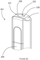
- FIG. 2C illustrates a detailed view of the end of the device 201 that is configured to engage with the consumable 202.
- the cap 210 of the device 201 includes an opening 221 to an internal cavity 222 defined by the cap 210.
- the opening 221 and the cavity 222 are formed so as to receive at least a portion of the consumable 202.
- a portion of the consumable 202 is received through the opening 221 and into the cavity 222.
- the downstream end 218 of the consumable 202 protrudes from the opening 221 and thus protrudes also from the device 201.
- the opening 221 includes laterally disposed notches 226. When a consumable 202 is received in the opening 221, these notches 226 remain open and could, for example, be used for retaining a cover to cover the end of the device 201.
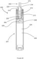
- Figure 2D shows a cross section through a central longitudinal plane through the device 201.
- the device 201 is shown with the consumable 202 engaged therewith.
- the device 201 comprises a heater 204 comprising heating element 223.
- the heater 204 forms part of the body 209 of the device 201 and is rigidly mounted to the body 209.
- the heater 204 is a rod heater with a heating element 223 having a circular transverse profile.
- the heater may be in the form of a blade heater (e.g. heating element with a rectangular transverse profile) or a tube heater (e.g. heating element with a tubular form).
- the heating element 223 of the heater 204 projects from an internal base of the cavity 222 along a longitudinal axis towards the opening 221. As is apparent from the figure, the length (i.e. along the longitudinal axis) of the heating element is less than a depth of the cavity 222. In this way, the heating element 223 does not protrude from or extend beyond the opening 221.
- the heating element 223 penetrates the aerosol-forming substrate 213 of the consumable 202.
- the heating element 223 extends for nearly the entire axial length of the aerosol-forming substrate 213 when inserted therein.
- the heater 204 is activated, heat is transferred radially from an outer circumferential surface the heating element 223 to the aerosol-forming substrate 213.
- the device 202 further comprises an electronics cavity 224.
- a power source in the form of a rechargeable battery 205 (a lithium ion battery), is located in electronics cavity 224.
- the device 202 includes a connector (i.e. forming part of an IO module of the device 201) in the form of a USB port 206.
- the connector may alternatively be, for example, a micro-USB port or a USB-C port for examples.
- the USB port 206 may be used to recharge the rechargeable battery 205.
- the device 201 includes the controller 208 (not shown) located in the electronics cavity 224.
- the controller comprises a microcontroller mounted on a printed circuit board (PCB).
- PCB printed circuit board
- the USB port 206 is also connected to the controller 208 (i.e. connected to the PCB and microcontroller).
- the device 201 also includes at least one haptic feedback output means coupled with the controller 208 and configured to generate haptic feedback output in response to receiving command from the controller 208.
- the at least one haptic feedback output means may be the vibration generator as described above, capable of generating vibrations of varying amplitude, frequency and number of vibrations / activations / "buzzes".
- the controller 208 is configured to control at least one function of the device 201.
- the controller 208 is configured to control the operation of the heater 204.
- Such control of the operation of the heater 204 may be accomplished by the controller 208 toggling the electrical connection of the rechargeable battery 205 to the heater 204.
- the controller 208 is configured to control the heater 204 in response to a user depressing the button 212. Depressing the button 212 may cause the controller to allow a voltage (from the rechargeable battery 205) to be applied to the heater 204 (so as to cause the heating element 223 to be heated).
- the controller 208 is further configured to convey the operating mode of the device 201 by haptic feedback output in response to the completion of a heat up phase of the device according to operating mode.
- the controller 208 activates the heater 204 to heat up to a target temperature during a heat up phase.
- the target temperature may be for example a predefined temperature set for each operating mode of the device 201.
- there are at least two operating modes such as normal mode and boost mode.
- the normal mode first mode
- the boost mode second mode
- the temperature maintenance phase during which the operating temperature of the heater may be maintained at the target temperature. It is during the maintenance phase that the user is intended to puff on the consumable.
- the operating mode of the device 201 is selected.
- the selection may be performed by the user, or the mode may be selected by the device controller 208.
- the controller 208 may have a default operating mode that is used unless the user intervenes to select a different operating mode.
- the controller 208 activates the heater 204 by supplying power to the heater in a heat-up phase during which the temperature of the heater is increased to the target temperature.
- the target temperature is different for different operating modes.
- the device 201 includes a heater temperature sensor which measures a current temperature of the heater 204.
- the current heater temperature may be periodically measured during the heat-up phase.
- the controller 208 instructs the haptic feedback means to output a haptic feedback signal.
- the intensity of the haptic feedback output is dependent on the operating mode. A more intense haptic feedback is provided for an operating mode with a higher target temperature.
- the controller 208 determines that the operating mode is a boost mode (second mode)
- the controller 208 activates the haptic feedback output means to generate a haptic feedback output with a higher intensity than in the normal mode (first mode).
- the operating temperature in the second mode is higher, and the user experience generally more intense. As such, a more intense haptic feedback in the second mode may allow the user to understand quickly which mode the device is operating in. The user experience may thus be improved.
- the feedback is not reliant on visual feedback, so this may be particularly useful for visually impaired uses.
- Intensity of haptic feedback may be changed by: increasing the amplitude of haptic feedback, increasing the frequency of haptic feedback, or increasing the number of haptic feedback activations.
- the haptic feedback in the first mode includes a lower number of haptic activations or "buzzes" than the haptic feedback in the second mode.
- the number of haptic feedback activations at the completion of the heat up phase in the boost mode (second mode) may be five.
- the number of haptic feedback activations at the completion of the heat up phase in the normal mode (first mode) may be three. The number of buzzes therefore corresponds to the temperature of the heater (i.e. more buzzes, higher temperature). Again, this is intuitive feedback for the user.
- the controller 208 also enables the user to predefine the haptic feedback output for different operating modes.
- the controller 208 receives user input on first or second intensity and define the haptic feedback output for each of the at least two operating modes based on the user input.
- the controller is also configured to control the LEDs 211 in response to (e.g. a detected) a condition of the device 201 or the consumable 202 or operating mode of the device 201.
- the controller may control the LEDs to indicate whether the device 201 is in an on state or an off state (e.g. one or more of the LEDs may be illuminated by the controller when the device is in an on state).
- the device 202 comprises a further input means (i.e. in addition to the button 212) in the form of a puff sensor 225.
- the puff sensor 225 is configured to detect a user drawing (i.e. inhaling) at the downstream end 218 of the consumable 202.
- the puff sensor 225 may, for example, be in the form of a pressure sensor, flowmeter or a microphone.
- the puff sensor 225 is operatively connected to the controller 208 in the electronics cavity 224, such that a signal from the puff sensor 225, indicative of a puff state (i.e. drawing or not drawing), forms an input to the controller 208 (and can thus be responded to by the controller 208).
Landscapes
- Engineering & Computer Science (AREA)
- Human Computer Interaction (AREA)
- Catching Or Destruction (AREA)
Description
- The present invention relates to a smoking substitute system and particularly, although not exclusively, to a smoking substitute device and a method of controlling operation of the smoking substitute device.
- The smoking of tobacco is generally considered to expose a smoker to potentially harmful substances. It is generally thought that a significant amount of the potentially harmful substances are generated through the heat caused by the burning and/or combustion of the tobacco and the constituents of the burnt tobacco in the tobacco smoke itself.
- Conventional combustible smoking articles, such as cigarettes, typically comprise a cylindrical rod of tobacco comprising shreds of tobacco which is surrounded by a wrapper, and usually also a cylindrical filter axially aligned in an abutting relationship with the wrapped tobacco rod. The filter typically comprises a filtration material which is circumscribed by a plug wrap. The wrapped tobacco rod and the filter are joined together by a wrapped band of tipping paper that circumscribes the entire length of the filter and an adjacent portion of the wrapped tobacco rod. A conventional cigarette of this type is used by lighting the end opposite to the filter, and burning the tobacco rod. The smoker receives mainstream smoke into their mouth by drawing on the mouth end or filter end of the cigarette.
- Combustion of organic material such as tobacco is known to produce tar and other potentially harmful by-products. There have been proposed various smoking substitute systems (or "substitute smoking systems") in order to avoid the smoking of tobacco.
- Such smoking substitute systems can form part of nicotine replacement therapies aimed at people who wish to stop smoking and overcome a dependence on nicotine.
- Smoking substitute systems include electronic systems that permit a user to simulate the act of smoking by producing an aerosol (also referred to as a "vapour") that is drawn into the lungs through the mouth (inhaled) and then exhaled. The inhaled aerosol typically bears nicotine and/or flavourings without, or with fewer of, the odour and health risks associated with traditional smoking.
- In general, smoking substitute systems are intended to provide a substitute for the rituals of smoking, whilst providing the user with a similar experience and satisfaction to those experienced with traditional smoking and with combustible tobacco products. Some smoking substitute systems use smoking substitute articles (also referred to as a "consumables") that are designed to resemble a traditional cigarette and are cylindrical in form with a mouthpiece at one end.
- The popularity and use of smoking substitute systems has grown rapidly in the past few years. Although originally marketed as an aid to assist habitual smokers wishing to quit tobacco smoking, consumers are increasingly viewing smoking substitute systems as desirable lifestyle accessories.
- There are a number of different categories of smoking substitute systems, each utilising a different smoking substitute approach.
- One approach for a smoking substitute system is the so-called Heated Tobacco ("HT") approach in which tobacco (rather than an "e-liquid") is heated or warmed to release vapour. HT is also known as "heat not burn" ("HNB"). The tobacco may be leaf tobacco or reconstituted tobacco. The vapour may contain nicotine and/or flavourings. In the HT approach the intention is that the tobacco is heated but not burned, i.e. the tobacco does not undergo combustion.
- A typical HT smoking substitute system may include a device and a consumable. The consumable may include the tobacco material. The device and consumable may be configured to be physically coupled together. In use, heat may be imparted to the tobacco material by a heating element of the device, wherein airflow through the tobacco material causes components in the tobacco material to be released as vapour. A vapour may also be formed from a carrier in the tobacco material (this carrier may for example include propylene glycol and/or vegetable glycerine) and additionally volatile compounds released from the tobacco. The released vapour may be entrained in the airflow drawn through the tobacco.
- As the vapour passes through the consumable (entrained in the airflow) from the location of vaporisation to an outlet of the consumable (e.g. a mouthpiece), the vapour cools and condenses to form an aerosol for inhalation by the user. The aerosol will normally contain the volatile compounds.
- In HT smoking substitute systems, heating as opposed to burning the tobacco material is believed to cause fewer, or smaller quantities, of the more harmful compounds ordinarily produced during smoking. Consequently, the HT approach may reduce the odour and/or health risks that can arise through the burning, combustion and pyrolytic degradation of tobacco.
- There may be a need for improved design of smoking substitute systems, in particular HT smoking substitute systems, to enhance the user experience and improve the function of the HT smoking substitute system.
- The present disclosure has been devised in the light of the above considerations.
WO 2015/177304 A discloses an electrically heated aerosol-generating system with end heater.US 2015/020825 A discloses an electronic smoking article with haptic feedback.US 2019/021400 A discloses a vaporisation device, method of using the device, a charging case, a kit, and a vibration assembly.US 2015/257445 A discloses an aerosol delivery device and related method and computer program product for controlling an aerosol delivery device based on input characteristics.US 2017/238617 A discloses an electronic vaporiser.US 2018/132529 A discloses an aerosol delivery device with integrated wireless connectivity for temperature monitoring - At its most general, the present invention relates to operating a smoking substitute system to provide haptic feedback indicating different operating modes of a smoking substitute device.
- According to a first aspect of the present invention, there is provided A method of providing operating a heated tobacco device, comprising: selecting a first operational mode or a second operational mode from at least two operational modes; when the first operational mode is selected, supplying power to a heater of the device to increase the temperature of the heater to a first target temperature; providing a first haptic feedback output in response to a current temperature of the heater reaching the first target temperature; when the second operational mode is selected, supplying power to the heater to increase the temperature of the heater to a second, different, target temperature; providing a second, different, haptic feedback output in response to a current temperature of the heater reaching the second target temperature.
- Optional features will now be set out. These are applicable singly or in any combination with any aspect.
- Optionally, the method further includes measuring the current temperature of the heater.
- Optionally, an intensity of the second haptic feedback output is higher than an intensity of the first haptic feedback output.
- Optionally, the second target temperature is higher than the first target temperature.
- Optionally, the second haptic feedback output includes a second number of haptic activations; and the first haptic feedback output includes a first number of haptic activations; wherein the second number is higher than the first number.
- Optionally, the first number is at least 2 and the second number is at least 4.
- Optionally, the method includes: providing a visual output simultaneously with each haptic feedback output.
- According to a second aspect, there is provided a heated tobacco device configured to implement the method of the first aspect.
- The device may comprise an elongate body. An end of the elongate body may be configured for engagement with an aerosol-forming article (e.g. a heated tobacco (HT) consumable. The device may comprise a cavity that is configured for receipt of at least a portion of the consumable (i.e. for engagement with the consumable). The aerosol-forming article may be of the type that comprises an aerosol former (e.g. carried by an aerosol-forming substrate).
- The device may comprise a heater for heating the aerosol-forming article. The heater may comprise a heating element, which may be in the form of a rod that extends from the body of the device. The heating element may extend from the end of the body that is configured for engagement with the aerosol-forming article.
- The heater (and thus the heating element) may be rigidly mounted to the body. The heating element may be elongate so as to define a longitudinal axis and may, for example, have a transverse profile (i.e. transverse to a longitudinal axis of the heating element) that is substantially circular (i.e. the heating element may be generally cylindrical). Alternatively, the heating element may have a transverse profile that is rectangular (i.e. the heater may be a "blade heater"). The heating element may alternatively be in the shape of a tube (i.e. the heater may be a "tube heater"). The heating element may take other forms (e.g. the heating element may have an elliptical transverse profile). The shape and/or size (e.g. diameter) of the transverse profile of the heating element may be generally consistent for the entire length (or substantially the entire length) of the heating element.
- The heating element may be between 15 mm and 25 mm long, e.g. between 18 mm and 20 mm long, e.g. around 19 mm long. The heating element may have a diameter of between 1.5 mm and 2.5 mm, e.g. a diameter between 2 mm and 2.3 mm, e.g. a diameter of around 2.15 mm.
- The heating element may be formed of ceramic. The heating element may comprise a core (e.g. a ceramic core) comprising Al2O3. The core of the heating element may have a diameter of 1.8 mm to 2.1 mm, e.g. between 1.9 mm and 2 mm. The heating element may comprise an outer layer (e.g. an outer ceramic layer) comprising AI2O3. The thickness of the outer layer may be between 160 µm and 220 µm, e.g. between 170 µm and 190 µm, e.g. around 180 µm. The heating element may comprise a heating track, which may extend longitudinally along the heating element. The heating track may be sandwiched between the outer layer and the core of the heating element. The heating track may comprise tungsten and/or rhenium. The heating track may have a thickness of around 20 µm.
- The heating element may be located in the cavity (of the device), and may extend (e.g. along a longitudinal axis) from an internal base of the cavity towards an opening of the cavity. The length of the heating element (i.e. along the longitudinal axis of the heater) may be less than the depth of the cavity. Hence, the heating element may extend for only a portion of the length of the cavity. That is, the heating element may not extend through (or beyond) the opening of the cavity.
- The heating element may be configured for insertion into an aerosol-forming article (e.g. a HT consumable) when an aerosol-forming article is received in the cavity. In that respect, a distal end (i.e. distal from a base of the heating element where it is mounted to the device) of the heating element may comprise a tapered portion, which may facilitate insertion of the heating element into the aerosol-forming article. The heating element may fully penetrate an aerosol-forming article when the aerosol-forming article is received in the cavity. That is, the entire length, or substantially the entire length, of the heating element may be received in the aerosol-forming article.
- The heating element may have a length that is less than, or substantially the same as, an axial length of an aerosol-forming substrate forming part of an aerosol-forming article (e.g. a HT consumable). Thus, when such an aerosol-forming article is engaged with the device, the heating element may only penetrate the aerosol-forming substrate, rather than other components of the aerosol-forming article. The heating element may penetrate the aerosol-forming substrate for substantially the entire axial length of the aerosol forming-substrate of the aerosol-forming article. Thus, heat may be transferred from (e.g. an outer circumferential surface of) the heating element to the surrounding aerosol-forming substrate, when penetrated by the heating element. That is, heat may be transferred radially outwardly (in the case of a cylindrical heating element) or e.g. radially inwardly (in the case of a tube heater).
- Where the heater is a tube heater, the heating element of the tube heater may surround at least a portion of the cavity. When the portion of the aerosol-forming article is received in the cavity, the heating element may surround a portion of the aerosol-forming article (i.e. so as to heat that portion of the aerosol-forming article). In particular, the heating element may surround an aerosol forming substrate of the aerosol-forming article. That is, when an aerosol-forming article is engaged with the device, the aerosol forming substrate of the aerosol-forming article may be located adjacent an inner surface of the (tubular) heating element. When the heating element is activated, heat may be transferred radially inwardly from the inner surface of the heating element to heat the aerosol forming substrate.
- The cavity may comprise a (e.g. circumferential) wall (or walls) and the (tubular) heating element may extend around at least a portion of the wall(s). In this way, the wall may be located between the inner surface of the heating element and an outer surface of the aerosol-forming article. The wall (or walls) of the cavity may be formed from a thermally conductive material (e.g. a metal) to allow heat conduction from the heating element to the aerosol-forming article. Thus, heat may be conducted from the heating element, through the cavity wall (or walls), to the aerosol-forming substrate of an aerosol-forming article received in the cavity.
- In some embodiments the device may comprise a cap disposed at the end of the body that is configured for engagement with an aerosol-forming article. Where the device comprises a heater having a heating element, the cap may at least partially enclose the heating element. The cap may be moveable between an open position in which access is provided to the heating element, and a closed position in which the cap at least partially encloses the heating element. The cap may be slideably engaged with the body of the device, and may be slideable between the open and closed positions.
- The cap may define at least a portion of the cavity of the device. That is, the cavity may be fully defined by the cap, or each of the cap and body may define a portion of the cavity. The cap may comprise an opening to the cavity. The opening may be configured for receipt of at least a portion of an aerosol-forming article. That is, an aerosol-forming article may be inserted through the opening and into the cavity (so as to be engaged with the device).
- The cap may be configured such that when an aerosol-forming article is engaged with the device (e.g. received in the cavity), only a portion of the aerosol-forming article is received in the cavity. That is, a portion of the aerosol-forming article (not received in the cavity) may protrude from (i.e. extend beyond) the opening. This (protruding) portion of the aerosol-forming article may be a terminal (e.g. mouth) end of the aerosol-forming article, which may be received in a user's mouth for the purpose of inhaling aerosol formed by the device.
- The device may comprise a power source or may be connectable to a power source (e.g. a power source separate to the device). The power source may be electrically connectable to the heater. In that respect, altering (e.g. toggling) the electrical connection of the power source to the heater may affect a state of the heater. For example, toggling the electrical connection of the power source to the heater may toggle the heater between an on state and an off state. The power source may be a power store. For example, the power source may be a battery or rechargeable battery (e.g. a lithium ion battery).
- The device may comprise an input connection (e.g. a USB port, Micro USB port, USB-C port, etc.). The input connection may be configured for connection to an external source of electrical power, such as a mains electrical supply outlet. The input connection may, in some cases, be used as a substitute for an internal power source (e.g. battery or rechargeable battery). That is, the input connection may be electrically connectable to the heater (for providing power to the heater). Hence, in some forms, the input connection may form at least part of the power source of the device.
- Where the power source comprises a rechargeable power source (such as a rechargeable battery), the input connection may be used to charge and recharge the power source.
- The device may comprise a user interface (Ul). In some embodiments the UI may include input means to receive operative commands from the user. The input means of the UI may allow the user to control at least one aspect of the operation of the device. In some embodiments the input means may comprise a power button to switch the device between an on state and an off state.
- In some embodiments the UI may additionally or alternatively comprise output means to convey information to the user. In some embodiments the output means may comprise a light to indicate a condition of the device (and/or the aerosol-forming article) to the user. The condition of the device (and/or aerosol-forming article) indicated to the user may comprise a condition indicative of the operation of the heater. For example, the condition may comprise whether the heater is in an off state or an on state. In some embodiments, the UI unit may comprise at least one of a button, a display, a touchscreen, a switch, a light, and the like. For example, the output means may comprise one or more (e.g. two, three, four, etc.) light-emitting diodes ("LEDs") that may be located on the body of the device.
- The device may further comprise a puff sensor (e.g. airflow sensor), which form part of the input means of the Ul. The puff sensor may be configured to detect a user drawing on an end (i.e. a terminal (mouth) end) of the aerosol-forming article. The puff sensor may, for example, be a pressure sensor or a microphone. The puff sensor may be configured to produce a signal indicative of a puff state. The signal may be indicative of the user drawing (an aerosol from the aerosol-forming article) such that it is e.g. in the form of a binary signal. Alternatively or additionally, the signal may be indicative of a characteristic of the draw (e.g. a flow rate of the draw, length of time of the draw, etc).
- The device comprises a controller configured to control at least one function of the device. The controller may comprise a microcontroller that may e.g. be mounted on a printed circuit board (PCB). The controller may also comprise a memory, e.g. non-volatile memory. The memory may include instructions, which, when implemented, may cause the controller to perform certain tasks or steps of a method. Where the device comprises an input connection, the controller may be connected to the input connection.
- The controller is configured to control the operation of the heater (and e.g. the heating element). Thus, the controller may be configured to control vaporisation of an aerosol forming part of an aerosol-forming article engaged with the device. The controller may be configured to control the voltage applied by power source to the heater. For example, the controller may be configured to toggle between applying a full output voltage (of the power source) to the heater and applying no voltage to the heater. Alternatively or additionally, the control unit may implement a more complex heater control protocol.
- The device may further comprise a voltage regulator to regulate the output voltage supplied by the power source to form a regulated voltage. The regulated voltage may subsequently be applied to the heater.
- In some embodiments, where the device comprises a Ul, the controller may be operatively connected to one or more components of the Ul. The controller may be configured to receive command signals from an input means of the Ul. The controller may be configured to control the heater in response to the command signals. For example, the controller may be configured to receive "on" and "off" command signals from the UI and, in response, may control the heater so as to be in a corresponding on or off state.
- The controller may be configured to send output signals to a component of the Ul. The UI may be configured to convey information to a user, via an output means, in response to such output signals (received from the controller). For example, where the device comprises one or more LEDs, the LEDs may be operatively connected to the controller. Hence, the controller may be configured to control the illumination of the LEDs (e.g. in response to an output signal). For example, the controller may be configured to control the illumination of the LEDs according to (e.g. an on or off) state of the heater.
- Where the device comprises a sensor (e.g. a puff/airflow sensor), the controller may be operatively connected to the sensor. The controller may be configured to receive a signal from the sensor (e.g. indicative of a condition of the device and/or engaged aerosol-forming article). The controller may be configured to control the heater, or an aspect of the output means, based on the signal from the sensor.
- The controller is configured to provide haptic feedback output of the operating mode of the device. By providing the haptic feedback output, the user is aware of the operating mode of the device based on different haptic feedback output without using a screen interface or using the LED lights.
- The device may comprise a wireless interface configured to communicate wirelessly (e.g. via Bluetooth (e.g. a Bluetooth low-energy connection) or Wi-Fi) with an external device. Similarly, the input connection may be configured for wired connection to an external device so as to provide communication between the device and the external device.
- The external device may be a mobile device. For example, the external device may be a smart phone, tablet, smart watch, or smart car. An application (e.g. app) may be installed on the external device (e.g. mobile device). The application may facilitate communication between the device and the external device via the wired or wireless connection.
- The wireless or wired interface may be configured to transfer signals between the external device and the controller of the device. In this respect, the controller may control an aspect of the device in response to a signal received from an external device. Alternatively or additionally, an external device may respond to a signal received from the device (e.g. from the controller of the device).
- In a third aspect, there is provided a system (e.g. a smoking substitute system) comprising a device according to the second aspect and an aerosol-forming article. The aerosol-forming article may comprise an aerosol-forming substrate at an upstream end of the aerosol-forming article. The article may be in the form of a smoking substitute article, e.g. heated tobacco (HT) consumable (also known as a heat-not-burn (HNB) consumable).
- As used herein, the terms "upstream" and "downstream" are intended to refer to the flow direction of the vapour/aerosol i.e. with the downstream end of the article/consumable being the mouth end or outlet where the aerosol exits the consumable for inhalation by the user. The upstream end of the article/consumable is the opposing end to the downstream end.
- The aerosol-forming substrate is capable of being heated to release at least one volatile compound that can form an aerosol. The aerosol-forming substrate may be located at the upstream end of the article/consumable.
- In order to generate an aerosol, the aerosol-forming substrate comprises at least one volatile compound that is intended to be vaporised/aerosolised and that may provide the user with a recreational and/or medicinal effect when inhaled. Suitable chemical and/or physiologically active volatile compounds include the group consisting of: nicotine, cocaine, caffeine, opiates and opoids, cathine and cathinone, kavalactones, mysticin, beta-carboline alkaloids, salvinorin A together with any combinations, functional equivalents to, and/or synthetic alternatives of the foregoing.
- The aerosol-forming substrate may comprise plant material. The plant material may comprise least one plant material selected from the list including Amaranthus dubius, Arctostaphylos uva-ursi (Bearberry), Argemone mexicana, Amica, Artemisia vulgaris, Yellow Tees, Galea zacatechichi, Canavalia maritima (Baybean), Cecropia mexicana (Guamura), Cestrum noctumum, Cynoglossum virginianum (wild comfrey), Cytisus scoparius, Damiana, Entada rheedii, Eschscholzia califomica (California Poppy), Fittonia albivenis, Hippobroma longiflora, Humulus japonica (Japanese Hops), Humulus lupulus (Hops), Lactuca virosa (Lettuce Opium), Laggera alata, Leonotis leonurus, Leonurus cardiaca (Motherwort), Leonurus sibiricus (Honeyweed), Lobelia cardinalis, Lobelia inflata (Indian-tobacco), Lobelia siphilitica, Nepeta cataria (Catnip), Nicotiana species (Tobacco), Nymphaea alba (White Lily), Nymphaea caerulea (Blue Lily), Opium poppy, Passiflora incamata (Passionflower), Pedicularis densiflora (Indian Warrior), Pedicularis groenlandica (Elephant's Head), Salvia divinorum, Salvia dorrii (Tobacco Sage), Salvia species (Sage), Scutellaria galericulata, Scutellaria lateriflora, Scutellaria nana, Scutellaria species (Skullcap), Sida acuta (Wireweed), Sida rhombifolia, Silene capensis, Syzygium aromaticum (Clove), Tagetes lucida (Mexican Tarragon), Tarchonanthus camphoratus, Tumera diffusa (Damiana), Verbascum (Mullein), Zamia latifolia (Maconha Brava) together with any combinations, functional equivalents to, and/or synthetic alternatives of the foregoing.
- The plant material may be tobacco. Any type of tobacco may be used. This includes, but is not limited to, flue-cured tobacco, burley tobacco, Maryland Tobacco, dark-air cured tobacco, oriental tobacco, dark-fired tobacco, perique tobacco and rustica tobacco. This also includes blends of the above mentioned tobaccos.
- The tobacco may comprise one or more of leaf tobacco, stem tobacco, tobacco powder, tobacco dust, tobacco derivatives, expanded tobacco, homogenised tobacco, shredded tobacco, extruded tobacco, cut rag tobacco and/or reconstituted tobacco (e.g. slurry recon or paper recon).
- The aerosol-forming substrate may comprise a gathered sheet of homogenised (e.g. paper/slurry recon) tobacco or gathered shreds/strips formed from such a sheet.
- The aerosol-forming substrate may comprise one or more additives selected from humectants, flavourants, fillers, aqueous/non-aqueous solvents and binders.
- The flavourant may be provided in solid or liquid form. It may include menthol, liquorice, chocolate, fruit flavour (including e.g. citrus, cherry etc.), vanilla, spice (e.g. ginger, cinnamon) and tobacco flavour. The flavourant may be evenly dispersed throughout the aerosol-forming substrate or may be provided in isolated locations and/or varying concentrations throughout the aerosol-forming substrate.
- The aerosol-forming substrate may be formed in a substantially cylindrical shape such that the article/consumable resembles a conventional cigarette. It may have a diameter of between 5 and 10mm e.g. between 6 and 9mm or 6 and 8mm e.g. around 7 mm. It may have an axial length of between 10 and 15mm e.g. between 11 and 14mm such as around 12 or 13mm.
- The article/consumable may comprise at least one filter element. There may be a terminal filter element at the downstream/mouth end of the article/consumable.
- The or at least one of the filter element(s) (e.g. the terminal filter element) may be comprised of cellulose acetate or polypropylene tow. The at least one filter element (e.g. the terminal filter element) may be comprised of activated charcoal. The at least one filter element (e.g. the terminal element) may be comprised of paper. The or each filter element may be at least partly (e.g. entirely) circumscribed with a plug wrap e.g. a paper plug wrap.
- The terminal filter element (at the downstream end of the article/consumable) may be joined to the upstream elements forming the article/consumable by a circumscribing tipping layer e.g. a tipping paper layer. The tipping paper may have an axial length longer than the axial length of the terminal filter element such that the tipping paper completely circumscribes the terminal filter element plus the wrapping layer surrounding any adjacent upstream element.
- In some embodiments, the article/consumable may comprise an aerosol-cooling element which is adapted to cool the aerosol generated from the aerosol-forming substrate (by heat exchange) before being inhaled by the user.
- The article/consumable may comprise a spacer element that defines a space or cavity between the aerosol-forming substrate and the downstream end of the consumable. The spacer element may comprise a cardboard tube. The spacer element may be circumscribed by the (paper) wrapping layer.
- According to a further aspect of the present invention, there is provided a method of using the system according to the third aspect, the method comprising inserting the aerosol-forming article into the device; and heating the article using the heater of the device.
- In some embodiments the method may comprise inserting the article into a cavity within a body of the device and penetrating the article with the heating element of the device upon insertion of the article. The invention includes the combination of the aspects and preferred features described except where such a combination is clearly impermissible or expressly avoided.
- The skilled person will appreciate that except where mutually exclusive, a feature or parameter described in relation to any one of the above aspects may be applied to any other aspect. Furthermore, except where mutually exclusive, any feature or parameter described herein may be applied to any aspect and/or combined with any other feature or parameter described herein within the scope of the appended claims.
- So that the invention may be understood, and so that further aspects and features thereof may be appreciated, embodiments illustrating the principles of the invention will now be discussed in further detail with reference to the accompanying figures, in which:
-
Figure 1A is a schematic of a smoking substitute system; -
Figure 1B is a schematic of a variation of the smoking substitute system ofFigure 1A ; -
Figure 2A is a front view of a first embodiment of a smoking substitute system with the consumable engaged with the device; -
Figure 2B is a front view of the first embodiment of the smoking substitute system with the consumable disengaged from the device; -
Figure 2C is a detailed view of an end of the device of the first embodiment of the smoking substitute system; -
Figure 2D is a section view of the first embodiment of the substitute smoking system. - Aspects and embodiments of the present invention will now be discussed with reference to the accompanying figures. Further aspects and embodiments will be apparent to those skilled in the art.
-
Figure 1A is a schematic providing a general overview of asmoking substitute system 100. Thesystem 100 includes asubstitute smoking device 101 and an aerosol-forming article in the form of a consumable 102, which comprises an aerosol former 103. The system is configured to vaporise the aerosol former by heating the aerosol former 103 (so as to form a vapour/aerosol for inhalation by a user). - In the illustrated system, the
heater 104 forms part of the consumable 102 and is configured to heat the aerosol former 103. Heat from theheater 104 vaporises the aerosol former 103 to produce a vapour. The vapour subsequently condenses to form an aerosol, which is ultimately inhaled by the user. - The
system 100 further comprises apower source 105 that forms part of thedevice 101. In other embodiments thepower source 105 may be external to (but connectable to) thedevice 101. Thepower source 105 is electrically connectable to theheater 104 such that thepower source 105 is able to supply power to the heater 104 (i.e. for the purpose of heating the aerosol former 103). Thus, control of the electrical connection of thepower source 105 to theheater 104 provides control of the state of theheater 104. Thepower source 105 may be a power store, for example a battery or rechargeable battery (e.g. a lithium ion battery). - The
system 100 further comprises an I/O module comprising a connector 106 (e.g. in the form of a USB port, Micro USB port, USB-C port, etc.). Theconnector 106 is configured for connection to an external source of electrical power, e.g. a mains electrical supply outlet. Theconnector 106 may be used in substitution for thepower source 105. That is theconnector 106 may be electrically connectable to theheater 104 so as to supply electricity to theheater 104. In such embodiments, the device may not include a power source, and the power source of the system may instead comprise theconnector 106 and an external source of electrical power (to which theconnector 106 provides electrical connection). - In some embodiments, the
connector 106 may be used to charge and recharge thepower source 105 where thepower source 104 includes a rechargeable battery. - The
system 100 also comprises a user interface (Ul) 107. Although not shown, the Ul 107 may include input means to receive commands from a user. The input means of the UI 107 allows the user to control at least one aspect of the operation of thesystem 100. The input means may, for example, be in the form of a button, touchscreen, switch, microphone, etc. - The UI 107 also comprises output means to convey information to the user. The output means may, for example, comprise lights (e.g. LEDs), a display screen, speaker, vibration generator, etc.
- The
system 100 further comprises acontroller 108 and amemory 109 coupled to thecontroller 108. In the illustrated embodiment, thecontroller 108 is a component of thedevice 101, but in other embodiments may be separate from (but connectable to) thedevice 101. Thecontroller 108 is configured to provide current state of the smoking consumable cycle based on a user request or detection of predetermined condition. Thememory 109 stores controller-executable instructions that causes thecontroller 108 to perform one or more functions. Thecontroller 108 is configured to control the operation of theheater 104 and, for example, may be configured to control the voltage applied from thepower source 105 to theheater 104. Thecontroller 108 may be configured to toggle the supply of power to theheater 105 between an on state, in which the full output voltage of thepower source 105 is applied to theheater 104, and an off state, in which the no voltage is applied to theheater 104. - Although not shown, the
system 100 may also comprise a voltage regulator to regulate the output voltage from thepower source 105 to form a regulated voltage. The regulated voltage may then be applied to theheater 104. - In addition to being connected to the
heater 104, thecontroller 108 is operatively connected to the UI 107. Thus, thecontroller 108 may receive an input signal from the input means of the UI 107. Similarly, thecontroller 108 may transmit output signals to the UI 107. In response, the output means of the UI 107 may convey information, based on the output signals, to a user. -
Figure 1B is a schematic showing a variation of thesystem 100 ofFigure 1A . In the system 100' ofFigure 1B , theheater 104 forms part of the consumable 102, rather than thedevice 101. In this variation, theheater 104 is electrically connectable to thepower source 105, for example, when the consumable 102 is engaged with thedevice 101.Figures 2A and 2B illustrate a heated-tobacco (HT)smoking substitute system 200. Thesystem 200 is an example of thesystems 100, 100' described in relation toFigures 1A or1B .System 200 includes anHT device 201 and anHT consumable 202. The description ofFigures 1A and1B above is applicable to thesystem 200 ofFigures 2A and 2B , and will thus not be repeated. - The
device 201 and the consumable 202 are configured such that the consumable 202 can be engaged with thedevice 201.Figure 2A shows thedevice 201 and the consumable 202 in an engaged state, whilstFigure 2B shows thedevice 201 and the consumable 202 in a disengaged state. - The
device 201 comprises abody 209 andcap 210. In use thecap 209 is engaged at an end of thebody 209. Although not apparent from the figures, thecap 210 is moveable relative to thebody 209. In particular, thecap 210 is slideable and can slide along a longitudinal axis of thebody 209. - The
device 201 comprises an output means (forming part of the UI of the device 201) in the form of a plurality of light-emitting diodes (LEDs) 211 arranged linearly along the longitudinal axis of thedevice 201 and on an outer surface of thebody 209 of thedevice 201. Abutton 212 is also arranged on an outer surface of thebody 209 of thedevice 201 and is axially spaced (i.e. along the longitudinal axis) from the plurality ofLEDs 211. -
Figure 2D shows a detailed section view of the consumable of 202 of thesystem 200. The consumable 202 generally resembles a cigarette. In that respect, the consumable 202 has a generally cylindrical form with a diameter of 7 mm and an axial length of 70 mm. The consumable 202 comprises anaerosol forming substrate 213, aterminal filter element 214, anupstream filter element 215 and aspacer element 216. In other embodiments, the consumable may further comprise a cooling element. A cooling element may exchange heat with vapour that is formed by the aerosol-formingsubstrate 213 in order to cool the vapour so as to facilitate condensation of the vapour. - The aerosol-forming
substrate 213 is substantially cylindrical and is located at an upstream end 217 of the consumable 202, and comprises the aerosol former of thesystem 200. In that respect, theaerosol forming substrate 213 is configured to be heated by thedevice 201 to release a vapour. The released vapour is subsequently entrained in an airflow flowing through the aerosol-formingsubstrate 213. The airflow is produced by the action of the user drawing on a downstream 218 (i.e. terminal or mouth end) of the consumable 202. - In the present embodiment, the
aerosol forming substrate 213 comprises tobacco material that may, for example, include any suitable parts of the tobacco plant (e.g. leaves, stems, roots, bark, seeds and flowers). The tobacco may comprise one or more of leaf tobacco, stem tobacco, tobacco powder, tobacco dust, tobacco derivatives, expanded tobacco, homogenised tobacco, shredded tobacco, extruded tobacco, cut rag tobacco and/or reconstituted tobacco (e.g. slurry recon or paper recon). For example, the aerosol-formingsubstrate 213 may comprise a gathered sheet of homogenised (e.g. paper/slurry recon) tobacco or gathered shreds/strips formed from such a sheet. - In order to generate an aerosol, the
aerosol forming substrate 213 comprises at least one volatile compound that is intended to be vaporised/aerosolised and that may provide the user with a recreational and/or medicinal effect when inhaled. The aerosol-formingsubstrate 213 may further comprise one or more additives. For example, such additives may be in the form of humectants (e.g. propylene glycol and/or vegetable glycerine), flavourants, fillers, aqueous/non-aqueous solvents and/or binders. - The
terminal filter element 214 is also substantially cylindrical, and is located downstream of theaerosol forming substrate 213 at the downstream end 218 of the consumable 202. Theterminal filter element 214 is in the form of a hollow bore filter element having a bore 219 (e.g. for airflow) formed therethrough. The diameter of the bore 219 is 2 mm. Theterminal filter element 214 is formed of a porous (e.g. monoacetate) filter material. As set forth above, the downstream end 218 of the consumable 202 (i.e. where theterminal filter 214 is located) forms a mouthpiece portion of the consumable 202 upon which the user draws. Airflow is drawn from the upstream end 217, thorough the components of the consumable 202, and out of the downstream end 218. The airflow is driven by the user drawing on the downstream end 218 (i.e. the mouthpiece portion) of the consumable 202. - The
upstream filter element 215 is located axially adjacent to the aerosol-formingsubstrate 213, between the aerosol-formingsubstrate 213 and theterminal filter element 214. Like theterminal filter 214, theupstream filter element 215 is in the form of a hollow bore filter element, such that it has a bore 220 extending axially therethrough. In this way, theupstream filter 215 may act as an airflow restrictor. Theupstream filter element 215 is formed of a porous (e.g. monoacetate) filter material. The bore 220 of theupstream filter element 214 has a larger diameter (3 mm) than theterminal filter element 214. - The
spacer 216 is in the form of a cardboard tube, which defines a cavity or chamber between theupstream filter element 215 and theterminal filter element 214. Thespacer 216 acts to allow both cooling and mixing of the vapour/aerosol from the aerosol-formingsubstrate 213. The spacer has an external diameter of 7 mm and an axial length of 14mm. - Although not apparent from the figure, the aerosol-forming
substrate 213,upstream filter 215 andspacer 216 are circumscribed by a paper wrapping layer. Theterminal filter 214 is circumscribed by a tipping layer that also circumscribes a portion of the paper wrapping layer (so as to connect theterminal filter 214 to the remaining components of the consumable 202). Theupstream filter 215 andterminal filter 214 are circumscribed by further wrapping layers in the form of plug wraps. - Returning now to the
device 201,Figure 2C illustrates a detailed view of the end of thedevice 201 that is configured to engage with the consumable 202. Thecap 210 of thedevice 201 includes anopening 221 to aninternal cavity 222 defined by thecap 210. Theopening 221 and thecavity 222 are formed so as to receive at least a portion of the consumable 202. During engagement of the consumable 202 with thedevice 201, a portion of the consumable 202 is received through theopening 221 and into thecavity 222. After engagement (seeFigure 2B ), the downstream end 218 of the consumable 202 protrudes from theopening 221 and thus protrudes also from thedevice 201. Theopening 221 includes laterally disposednotches 226. When a consumable 202 is received in theopening 221, thesenotches 226 remain open and could, for example, be used for retaining a cover to cover the end of thedevice 201. -
Figure 2D shows a cross section through a central longitudinal plane through thedevice 201. Thedevice 201 is shown with the consumable 202 engaged therewith. - The
device 201 comprises aheater 204 comprisingheating element 223. Theheater 204 forms part of thebody 209 of thedevice 201 and is rigidly mounted to thebody 209. In the illustrated embodiment, theheater 204 is a rod heater with aheating element 223 having a circular transverse profile. In other embodiments the heater may be in the form of a blade heater (e.g. heating element with a rectangular transverse profile) or a tube heater (e.g. heating element with a tubular form). - The
heating element 223 of theheater 204 projects from an internal base of thecavity 222 along a longitudinal axis towards theopening 221. As is apparent from the figure, the length (i.e. along the longitudinal axis) of the heating element is less than a depth of thecavity 222. In this way, theheating element 223 does not protrude from or extend beyond theopening 221. - When the consumable 202 is received in the cavity 222 (as is shown in
Figure 2D ), theheating element 223 penetrates the aerosol-formingsubstrate 213 of the consumable 202. In particular, theheating element 223 extends for nearly the entire axial length of the aerosol-formingsubstrate 213 when inserted therein. Thus, when theheater 204 is activated, heat is transferred radially from an outer circumferential surface theheating element 223 to the aerosol-formingsubstrate 213. - The
device 202 further comprises anelectronics cavity 224. A power source, in the form of a rechargeable battery 205 (a lithium ion battery), is located inelectronics cavity 224. - The
device 202 includes a connector (i.e. forming part of an IO module of the device 201) in the form of a USB port 206. The connector may alternatively be, for example, a micro-USB port or a USB-C port for examples. The USB port 206 may be used to recharge therechargeable battery 205. - The
device 201 includes the controller 208 (not shown) located in theelectronics cavity 224. The controller comprises a microcontroller mounted on a printed circuit board (PCB). The USB port 206 is also connected to the controller 208 (i.e. connected to the PCB and microcontroller). - The
device 201 also includes at least one haptic feedback output means coupled with the controller 208 and configured to generate haptic feedback output in response to receiving command from the controller 208. In one example, the at least one haptic feedback output means may be the vibration generator as described above, capable of generating vibrations of varying amplitude, frequency and number of vibrations / activations / "buzzes". - The controller 208 is configured to control at least one function of the
device 201. For example, the controller 208 is configured to control the operation of theheater 204. Such control of the operation of theheater 204 may be accomplished by the controller 208 toggling the electrical connection of therechargeable battery 205 to theheater 204. For example, the controller 208 is configured to control theheater 204 in response to a user depressing thebutton 212. Depressing thebutton 212 may cause the controller to allow a voltage (from the rechargeable battery 205) to be applied to the heater 204 (so as to cause theheating element 223 to be heated). - The controller 208 is further configured to convey the operating mode of the
device 201 by haptic feedback output in response to the completion of a heat up phase of the device according to operating mode. During operation of thedevice 201, the controller 208 activates theheater 204 to heat up to a target temperature during a heat up phase. The target temperature may be for example a predefined temperature set for each operating mode of thedevice 201. In one aspect, there are at least two operating modes such as normal mode and boost mode. For example, the normal mode (first mode) may have a target temperature of 315 degrees Celsius. For example, the boost mode (second mode) may have a target temperature of 345 degrees Celsius. Following the heat up phase, there is a temperature maintenance phase during which the operating temperature of the heater may be maintained at the target temperature. It is during the maintenance phase that the user is intended to puff on the consumable. - Before heat up, the operating mode of the
device 201 is selected. The selection may be performed by the user, or the mode may be selected by the device controller 208. For example, the controller 208 may have a default operating mode that is used unless the user intervenes to select a different operating mode. The controller 208 activates theheater 204 by supplying power to the heater in a heat-up phase during which the temperature of the heater is increased to the target temperature. The target temperature is different for different operating modes. - The
device 201 includes a heater temperature sensor which measures a current temperature of theheater 204. The current heater temperature may be periodically measured during the heat-up phase. When the current temperature of theheater 204 is measured to be equal to the target temperature for the operating mode, the controller 208 instructs the haptic feedback means to output a haptic feedback signal. The intensity of the haptic feedback output is dependent on the operating mode. A more intense haptic feedback is provided for an operating mode with a higher target temperature. - If the controller 208 determines that the operating mode is a boost mode (second mode), then the controller 208 activates the haptic feedback output means to generate a haptic feedback output with a higher intensity than in the normal mode (first mode). The operating temperature in the second mode is higher, and the user experience generally more intense. As such, a more intense haptic feedback in the second mode may allow the user to understand quickly which mode the device is operating in. The user experience may thus be improved. The feedback is not reliant on visual feedback, so this may be particularly useful for visually impaired uses.
- Intensity of haptic feedback may be changed by: increasing the amplitude of haptic feedback, increasing the frequency of haptic feedback, or increasing the number of haptic feedback activations. In some embodiments, the haptic feedback in the first mode includes a lower number of haptic activations or "buzzes" than the haptic feedback in the second mode. For example, the number of haptic feedback activations at the completion of the heat up phase in the boost mode (second mode) may be five. For example, the number of haptic feedback activations at the completion of the heat up phase in the normal mode (first mode) may be three. The number of buzzes therefore corresponds to the temperature of the heater (i.e. more buzzes, higher temperature). Again, this is intuitive feedback for the user.
- The controller 208 also enables the user to predefine the haptic feedback output for different operating modes. In one aspect, the controller 208 receives user input on first or second intensity and define the haptic feedback output for each of the at least two operating modes based on the user input.
- The controller is also configured to control the
LEDs 211 in response to (e.g. a detected) a condition of thedevice 201 or the consumable 202 or operating mode of thedevice 201. For example, the controller may control the LEDs to indicate whether thedevice 201 is in an on state or an off state (e.g. one or more of the LEDs may be illuminated by the controller when the device is in an on state). - The
device 202 comprises a further input means (i.e. in addition to the button 212) in the form of apuff sensor 225. Thepuff sensor 225 is configured to detect a user drawing (i.e. inhaling) at the downstream end 218 of the consumable 202. Thepuff sensor 225 may, for example, be in the form of a pressure sensor, flowmeter or a microphone. Thepuff sensor 225 is operatively connected to the controller 208 in theelectronics cavity 224, such that a signal from thepuff sensor 225, indicative of a puff state (i.e. drawing or not drawing), forms an input to the controller 208 (and can thus be responded to by the controller 208). The features disclosed in the foregoing description, or in the following claims, or in the accompanying drawings, expressed in their specific forms or in terms of a means for performing the disclosed function, or a method or process for obtaining the disclosed results, as appropriate, may, separately, or in any combination of such features, be utilised for realising the invention in diverse forms thereof. - While the invention has been described in conjunction with the exemplary embodiments described above, many equivalent modifications and variations will be apparent to those skilled in the art when given this disclosure. Accordingly, the exemplary embodiments of the invention set forth above are considered to be illustrative and not limiting. Various changes to the described embodiments may be made without departing from the scope of the invention.
- For the avoidance of any doubt, any theoretical explanations provided herein are provided for the purposes of improving the understanding of a reader. The inventors do not wish to be bound by any of these theoretical explanations.
- Any section headings used herein are for organizational purposes only and are not to be construed as limiting the subject matter described.
- Throughout this specification, including the claims which follow, unless the context requires otherwise, the words "have", "comprise", and "include", and variations such as "having", "comprises", "comprising", and "including" will be understood to imply the inclusion of a stated integer or step or group of integers or steps but not the exclusion of any other integer or step or group of integers or steps.
- It must be noted that, as used in the specification and the appended claims, the singular forms "a," "an," and "the" include plural referents unless the context clearly dictates otherwise. Ranges may be expressed herein as from "about" one particular value, and/or to "about" another particular value. When such a range is expressed, another embodiment includes from the one particular value and/or to the other particular value. Similarly, when values are expressed as approximations, by the use of the antecedent "about," it will be understood that the particular value forms another embodiment. The term "about" in relation to a numerical value is optional and means, for example, +/- 10%.
- The words "preferred" and "preferably" are used herein refer to embodiments of the invention that may provide certain benefits under some circumstances. It is to be appreciated, however, that other embodiments may also be preferred under the same or different circumstances. The recitation of one or more preferred embodiments therefore does not mean or imply that other embodiments are not useful, and is not intended to exclude other embodiments from the scope of the disclosure, or from the scope of the claims.
Claims (9)
- A method of operating a heated tobacco device, comprising:selecting a first operational mode or a second operational mode from at least two operational modes;when the first operational mode is selected, supplying power to a heater of the device to increase the temperature of the heater to a first target temperature;
providing a first haptic feedback output in response to a current temperature of the heater reaching the first target temperature;when the second operational mode is selected, supplying power to the heater to increase the temperature of the heater to a second, different, target temperature;
providing a second, different, haptic feedback output in response to a current temperature of the heater reaching the second target temperature. - The method according to claim 1, including measuring the current temperature of the heater.
- The method according to claim 1 or claim 2, wherein an intensity of the second haptic feedback output is higher than an intensity of the first haptic feedback output.
- The method according to claim 3, wherein the second target temperature is higher than the first target temperature.
- The method according to claim 3 or claim 4, wherein the second haptic feedback output includes a second number of haptic activations; and the first haptic feedback output includes a first number of haptic activations; wherein the second number is higher than the first number.
- The method according to claim 5, wherein the first number is at least 2 and the second number is at least 4.
- The method according to any preceding claim, including:
providing a visual output simultaneously with each haptic feedback output. - A heated tobacco device comprising:a heater,a controller configured to control the operation of the heater,, anda haptic feedback output means coupled to the controller and configured to generate haptic feedback output in response to receiving command from the controller,characterised in that the device is configured to implement the method of any preceding claim.
- A heated tobacco system, including:a device according to claim 8; anda heated tobacco consumable.
Priority Applications (2)
| Application Number | Priority Date | Filing Date | Title |
|---|---|---|---|
| PL19020184.8T PL3711552T3 (en) | 2019-03-22 | 2019-03-22 | Smoking substitute system |
| EP19020184.8A EP3711552B1 (en) | 2019-03-22 | 2019-03-22 | Smoking substitute system |
Applications Claiming Priority (1)
| Application Number | Priority Date | Filing Date | Title |
|---|---|---|---|
| EP19020184.8A EP3711552B1 (en) | 2019-03-22 | 2019-03-22 | Smoking substitute system |
Publications (2)
| Publication Number | Publication Date |
|---|---|
| EP3711552A1 EP3711552A1 (en) | 2020-09-23 |
| EP3711552B1 true EP3711552B1 (en) | 2023-06-21 |
Family
ID=65955004
Family Applications (1)
| Application Number | Title | Priority Date | Filing Date |
|---|---|---|---|
| EP19020184.8A Active EP3711552B1 (en) | 2019-03-22 | 2019-03-22 | Smoking substitute system |
Country Status (2)
| Country | Link |
|---|---|
| EP (1) | EP3711552B1 (en) |
| PL (1) | PL3711552T3 (en) |
Families Citing this family (7)
| Publication number | Priority date | Publication date | Assignee | Title |
|---|---|---|---|---|
| US11789476B2 (en) | 2021-01-18 | 2023-10-17 | Altria Client Services Llc | Heat-not-burn (HNB) aerosol-generating devices including intra-draw heater control, and methods of controlling a heater |
| US12520880B2 (en) | 2021-01-18 | 2026-01-13 | Altria Client Services Llc | Heat-not-burn (HNB) aerosol-generating devices including energy based heater control, and methods of controlling a heater |
| GB202115188D0 (en) * | 2021-10-22 | 2021-12-08 | Nicoventures Trading Ltd | Aerosol provision system |
| GB202115192D0 (en) * | 2021-10-22 | 2021-12-08 | Nicoventures Trading Ltd | Aerosol provision system |
| US20240122269A1 (en) | 2022-10-14 | 2024-04-18 | Airo Brands Inc. | A dispensing device with an electromechanical feedback system and methods of use |
| US12302951B2 (en) | 2023-07-07 | 2025-05-20 | Airo Brands Inc. | Dispensing device with an electromechanical feedback system and methods of use |
| WO2025126333A1 (en) * | 2023-12-12 | 2025-06-19 | 日本たばこ産業株式会社 | Aerosol generation device |
Citations (12)
| Publication number | Priority date | Publication date | Assignee | Title |
|---|---|---|---|---|
| WO2013025921A1 (en) | 2011-08-16 | 2013-02-21 | Ploom, Inc. | Low temperature electronic vaporization device and methods |
| WO2014058678A1 (en) | 2012-10-08 | 2014-04-17 | R. J. Reynolds Tobacco Company | An electronic smoking article and associated method |
| US20150020825A1 (en) | 2013-07-19 | 2015-01-22 | R.J. Reynolds Tobacco Company | Electronic smoking article with haptic feedback |
| US20160338412A1 (en) | 2005-07-19 | 2016-11-24 | James Monsees | Devices for vaporization of a substance |
| US20170055583A1 (en) | 2015-08-31 | 2017-03-02 | British American Tobacco (Investments) Limited | Apparatus for heating smokable material |
| US20170238617A1 (en) | 2015-11-06 | 2017-08-24 | Mark Scatterday | Electronic vaporizer |
| US20170259170A1 (en) | 2016-03-10 | 2017-09-14 | Pax Labs, Inc. | Vaporization device having integrated games |
| EP3249488A1 (en) | 2015-01-22 | 2017-11-29 | Joyetech (Changzhou) Electronics Co., Ltd. | Temperature control system and control method thereof, and electronic cigarette containing said temperature control system |
| US20180035714A1 (en) | 2016-08-08 | 2018-02-08 | Rai Strategic Holdings, Inc. | Boost converter for an aerosol delivery device |
| US9936735B1 (en) | 2015-05-04 | 2018-04-10 | Bonvi Water, Inc. | Electronic cigarette |
| KR20180070443A (en) | 2016-12-16 | 2018-06-26 | 주식회사 케이티앤지 | Method and apparatus for providing adaptive feedback through puff recognition |
| CN207855021U (en) | 2017-11-08 | 2018-09-14 | 深圳市舜宝科技有限公司 | A kind of electronics tobacco rod and electronic cigarette system with temperature-prompting function |
Family Cites Families (4)
| Publication number | Priority date | Publication date | Assignee | Title |
|---|---|---|---|---|
| US11696604B2 (en) * | 2014-03-13 | 2023-07-11 | Rai Strategic Holdings, Inc. | Aerosol delivery device and related method and computer program product for controlling an aerosol delivery device based on input characteristics |
| US11930566B2 (en) * | 2014-05-21 | 2024-03-12 | Philip Morris Products S.A. | Electrically heated aerosol-generating system with end heater |
| US20190021400A1 (en) * | 2016-05-18 | 2019-01-24 | Gsw Creative Corporation | Vaporization device, method of using the device, a charging case, a kit, and a vibration assembly |
| US20180132529A1 (en) * | 2016-11-14 | 2018-05-17 | Rai Strategic Holdings, Inc. | Aerosol delivery device with integrated wireless connectivity for temperature monitoring |
-
2019
- 2019-03-22 PL PL19020184.8T patent/PL3711552T3/en unknown
- 2019-03-22 EP EP19020184.8A patent/EP3711552B1/en active Active
Patent Citations (12)
| Publication number | Priority date | Publication date | Assignee | Title |
|---|---|---|---|---|
| US20160338412A1 (en) | 2005-07-19 | 2016-11-24 | James Monsees | Devices for vaporization of a substance |
| WO2013025921A1 (en) | 2011-08-16 | 2013-02-21 | Ploom, Inc. | Low temperature electronic vaporization device and methods |
| WO2014058678A1 (en) | 2012-10-08 | 2014-04-17 | R. J. Reynolds Tobacco Company | An electronic smoking article and associated method |
| US20150020825A1 (en) | 2013-07-19 | 2015-01-22 | R.J. Reynolds Tobacco Company | Electronic smoking article with haptic feedback |
| EP3249488A1 (en) | 2015-01-22 | 2017-11-29 | Joyetech (Changzhou) Electronics Co., Ltd. | Temperature control system and control method thereof, and electronic cigarette containing said temperature control system |
| US9936735B1 (en) | 2015-05-04 | 2018-04-10 | Bonvi Water, Inc. | Electronic cigarette |
| US20170055583A1 (en) | 2015-08-31 | 2017-03-02 | British American Tobacco (Investments) Limited | Apparatus for heating smokable material |
| US20170238617A1 (en) | 2015-11-06 | 2017-08-24 | Mark Scatterday | Electronic vaporizer |
| US20170259170A1 (en) | 2016-03-10 | 2017-09-14 | Pax Labs, Inc. | Vaporization device having integrated games |
| US20180035714A1 (en) | 2016-08-08 | 2018-02-08 | Rai Strategic Holdings, Inc. | Boost converter for an aerosol delivery device |
| KR20180070443A (en) | 2016-12-16 | 2018-06-26 | 주식회사 케이티앤지 | Method and apparatus for providing adaptive feedback through puff recognition |
| CN207855021U (en) | 2017-11-08 | 2018-09-14 | 深圳市舜宝科技有限公司 | A kind of electronics tobacco rod and electronic cigarette system with temperature-prompting function |
Also Published As
| Publication number | Publication date |
|---|---|
| PL3711552T3 (en) | 2023-10-23 |
| EP3711552A1 (en) | 2020-09-23 |
Similar Documents
| Publication | Publication Date | Title |
|---|---|---|
| EP3711552B1 (en) | Smoking substitute system | |
| EP3941252B1 (en) | Smoking substitute system | |
| EP3941247B1 (en) | Smoking substitute system | |
| EP3941250B1 (en) | Smoking substitute system | |
| EP3711550A1 (en) | Smoking substitute system | |
| EP3941239B1 (en) | Smoking substitute system | |
| EP3941251B1 (en) | Smoking substitute system | |
| EP3941266B1 (en) | Smoking substitute system | |
| EP3941234B1 (en) | Smoking substitute system | |
| EP3711518A1 (en) | Smoking substitute system | |
| WO2020193211A1 (en) | Smoking substitute system | |
| EP3941238A1 (en) | Heating apparatus for smoking substitute system | |
| EP3942667A1 (en) | Smoking substitute system | |
| EP3711540A1 (en) | Smoking substitute system | |
| EP3941235B1 (en) | Smoking substitute system | |
| EP3711549A1 (en) | Smoking substitute system | |
| EP3711517A1 (en) | Smoking substitute system | |
| EP3711559A1 (en) | Smoking substitute system |
Legal Events
| Date | Code | Title | Description |
|---|---|---|---|
| PUAI | Public reference made under article 153(3) epc to a published international application that has entered the european phase |
Free format text: ORIGINAL CODE: 0009012 |
|
| STAA | Information on the status of an ep patent application or granted ep patent |
Free format text: STATUS: THE APPLICATION HAS BEEN PUBLISHED |
|
| AK | Designated contracting states |
Kind code of ref document: A1 Designated state(s): AL AT BE BG CH CY CZ DE DK EE ES FI FR GB GR HR HU IE IS IT LI LT LU LV MC MK MT NL NO PL PT RO RS SE SI SK SM TR |
|
| AX | Request for extension of the european patent |
Extension state: BA ME |
|
| STAA | Information on the status of an ep patent application or granted ep patent |
Free format text: STATUS: REQUEST FOR EXAMINATION WAS MADE |
|
| 17P | Request for examination filed |
Effective date: 20210624 |
|
| RBV | Designated contracting states (corrected) |
Designated state(s): AL AT BE BG CH CY CZ DE DK EE ES FI FR GB GR HR HU IE IS IT LI LT LU LV MC MK MT NL NO PL PT RO RS SE SI SK SM TR |
|
| REG | Reference to a national code |
Ref country code: DE Ref legal event code: R079 Ref document number: 602019031224 Country of ref document: DE Free format text: PREVIOUS MAIN CLASS: A24F0047000000 Ipc: A24F0040500000 |
|
| RIC1 | Information provided on ipc code assigned before grant |
Ipc: A24F 40/60 20200101ALI20221103BHEP Ipc: A24F 40/50 20200101AFI20221103BHEP |
|
| GRAP | Despatch of communication of intention to grant a patent |
Free format text: ORIGINAL CODE: EPIDOSNIGR1 |
|
| STAA | Information on the status of an ep patent application or granted ep patent |
Free format text: STATUS: GRANT OF PATENT IS INTENDED |
|
| INTG | Intention to grant announced |
Effective date: 20230103 |
|
| GRAS | Grant fee paid |
Free format text: ORIGINAL CODE: EPIDOSNIGR3 |
|
| GRAA | (expected) grant |
Free format text: ORIGINAL CODE: 0009210 |
|
| STAA | Information on the status of an ep patent application or granted ep patent |
Free format text: STATUS: THE PATENT HAS BEEN GRANTED |
|
| REG | Reference to a national code |
Ref country code: DE Ref legal event code: R081 Ref document number: 602019031224 Country of ref document: DE Owner name: IMPERIAL TOBACCO LIMITED, GB Free format text: FORMER OWNER: NERUDIA LIMITED, LIVERPOOL, MERSEYSIDE, GB |
|
| AK | Designated contracting states |
Kind code of ref document: B1 Designated state(s): AL AT BE BG CH CY CZ DE DK EE ES FI FR GB GR HR HU IE IS IT LI LT LU LV MC MK MT NL NO PL PT RO RS SE SI SK SM TR |
|
| REG | Reference to a national code |
Ref country code: CH Ref legal event code: EP |
|
| RAP2 | Party data changed (patent owner data changed or rights of a patent transferred) |
Owner name: IMPERIAL TOBACCO LIMITED |
|
| REG | Reference to a national code |
Ref country code: DE Ref legal event code: R096 Ref document number: 602019031224 Country of ref document: DE |
|
| P01 | Opt-out of the competence of the unified patent court (upc) registered |
Effective date: 20230606 |
|
| REG | Reference to a national code |
Ref country code: AT Ref legal event code: REF Ref document number: 1580246 Country of ref document: AT Kind code of ref document: T Effective date: 20230715 |
|
| REG | Reference to a national code |
Ref country code: IE Ref legal event code: FG4D |
|
| REG | Reference to a national code |
Ref country code: LT Ref legal event code: MG9D |
|
| REG | Reference to a national code |
Ref country code: NL Ref legal event code: MP Effective date: 20230621 |
|
| PG25 | Lapsed in a contracting state [announced via postgrant information from national office to epo] |
Ref country code: SE Free format text: LAPSE BECAUSE OF FAILURE TO SUBMIT A TRANSLATION OF THE DESCRIPTION OR TO PAY THE FEE WITHIN THE PRESCRIBED TIME-LIMIT Effective date: 20230621 Ref country code: NO Free format text: LAPSE BECAUSE OF FAILURE TO SUBMIT A TRANSLATION OF THE DESCRIPTION OR TO PAY THE FEE WITHIN THE PRESCRIBED TIME-LIMIT Effective date: 20230921 |
|
| REG | Reference to a national code |
Ref country code: AT Ref legal event code: MK05 Ref document number: 1580246 Country of ref document: AT Kind code of ref document: T Effective date: 20230621 |
|
| PG25 | Lapsed in a contracting state [announced via postgrant information from national office to epo] |
Ref country code: RS Free format text: LAPSE BECAUSE OF FAILURE TO SUBMIT A TRANSLATION OF THE DESCRIPTION OR TO PAY THE FEE WITHIN THE PRESCRIBED TIME-LIMIT Effective date: 20230621 Ref country code: NL Free format text: LAPSE BECAUSE OF FAILURE TO SUBMIT A TRANSLATION OF THE DESCRIPTION OR TO PAY THE FEE WITHIN THE PRESCRIBED TIME-LIMIT Effective date: 20230621 Ref country code: LV Free format text: LAPSE BECAUSE OF FAILURE TO SUBMIT A TRANSLATION OF THE DESCRIPTION OR TO PAY THE FEE WITHIN THE PRESCRIBED TIME-LIMIT Effective date: 20230621 Ref country code: LT Free format text: LAPSE BECAUSE OF FAILURE TO SUBMIT A TRANSLATION OF THE DESCRIPTION OR TO PAY THE FEE WITHIN THE PRESCRIBED TIME-LIMIT Effective date: 20230621 Ref country code: HR Free format text: LAPSE BECAUSE OF FAILURE TO SUBMIT A TRANSLATION OF THE DESCRIPTION OR TO PAY THE FEE WITHIN THE PRESCRIBED TIME-LIMIT Effective date: 20230621 Ref country code: GR Free format text: LAPSE BECAUSE OF FAILURE TO SUBMIT A TRANSLATION OF THE DESCRIPTION OR TO PAY THE FEE WITHIN THE PRESCRIBED TIME-LIMIT Effective date: 20230922 |
|
| PG25 | Lapsed in a contracting state [announced via postgrant information from national office to epo] |
Ref country code: FI Free format text: LAPSE BECAUSE OF FAILURE TO SUBMIT A TRANSLATION OF THE DESCRIPTION OR TO PAY THE FEE WITHIN THE PRESCRIBED TIME-LIMIT Effective date: 20230621 |
|
| PG25 | Lapsed in a contracting state [announced via postgrant information from national office to epo] |
Ref country code: SK Free format text: LAPSE BECAUSE OF FAILURE TO SUBMIT A TRANSLATION OF THE DESCRIPTION OR TO PAY THE FEE WITHIN THE PRESCRIBED TIME-LIMIT Effective date: 20230621 |
|
| PG25 | Lapsed in a contracting state [announced via postgrant information from national office to epo] |
Ref country code: ES Free format text: LAPSE BECAUSE OF FAILURE TO SUBMIT A TRANSLATION OF THE DESCRIPTION OR TO PAY THE FEE WITHIN THE PRESCRIBED TIME-LIMIT Effective date: 20230621 |
|
| PG25 | Lapsed in a contracting state [announced via postgrant information from national office to epo] |
Ref country code: IS Free format text: LAPSE BECAUSE OF FAILURE TO SUBMIT A TRANSLATION OF THE DESCRIPTION OR TO PAY THE FEE WITHIN THE PRESCRIBED TIME-LIMIT Effective date: 20231021 |
|
| PG25 | Lapsed in a contracting state [announced via postgrant information from national office to epo] |
Ref country code: SM Free format text: LAPSE BECAUSE OF FAILURE TO SUBMIT A TRANSLATION OF THE DESCRIPTION OR TO PAY THE FEE WITHIN THE PRESCRIBED TIME-LIMIT Effective date: 20230621 Ref country code: SK Free format text: LAPSE BECAUSE OF FAILURE TO SUBMIT A TRANSLATION OF THE DESCRIPTION OR TO PAY THE FEE WITHIN THE PRESCRIBED TIME-LIMIT Effective date: 20230621 Ref country code: RO Free format text: LAPSE BECAUSE OF FAILURE TO SUBMIT A TRANSLATION OF THE DESCRIPTION OR TO PAY THE FEE WITHIN THE PRESCRIBED TIME-LIMIT Effective date: 20230621 Ref country code: PT Free format text: LAPSE BECAUSE OF FAILURE TO SUBMIT A TRANSLATION OF THE DESCRIPTION OR TO PAY THE FEE WITHIN THE PRESCRIBED TIME-LIMIT Effective date: 20231023 Ref country code: IS Free format text: LAPSE BECAUSE OF FAILURE TO SUBMIT A TRANSLATION OF THE DESCRIPTION OR TO PAY THE FEE WITHIN THE PRESCRIBED TIME-LIMIT Effective date: 20231021 Ref country code: ES Free format text: LAPSE BECAUSE OF FAILURE TO SUBMIT A TRANSLATION OF THE DESCRIPTION OR TO PAY THE FEE WITHIN THE PRESCRIBED TIME-LIMIT Effective date: 20230621 Ref country code: EE Free format text: LAPSE BECAUSE OF FAILURE TO SUBMIT A TRANSLATION OF THE DESCRIPTION OR TO PAY THE FEE WITHIN THE PRESCRIBED TIME-LIMIT Effective date: 20230621 Ref country code: CZ Free format text: LAPSE BECAUSE OF FAILURE TO SUBMIT A TRANSLATION OF THE DESCRIPTION OR TO PAY THE FEE WITHIN THE PRESCRIBED TIME-LIMIT Effective date: 20230621 Ref country code: AT Free format text: LAPSE BECAUSE OF FAILURE TO SUBMIT A TRANSLATION OF THE DESCRIPTION OR TO PAY THE FEE WITHIN THE PRESCRIBED TIME-LIMIT Effective date: 20230621 |
|
| REG | Reference to a national code |
Ref country code: DE Ref legal event code: R026 Ref document number: 602019031224 Country of ref document: DE |
|
| PLBI | Opposition filed |
Free format text: ORIGINAL CODE: 0009260 |
|
| PLAX | Notice of opposition and request to file observation + time limit sent |
Free format text: ORIGINAL CODE: EPIDOSNOBS2 |
|
| PG25 | Lapsed in a contracting state [announced via postgrant information from national office to epo] |
Ref country code: DK Free format text: LAPSE BECAUSE OF FAILURE TO SUBMIT A TRANSLATION OF THE DESCRIPTION OR TO PAY THE FEE WITHIN THE PRESCRIBED TIME-LIMIT Effective date: 20230621 |
|
| 26 | Opposition filed |
Opponent name: NICOVENTURES TRADING LIMITED Effective date: 20240321 |
|
| PG25 | Lapsed in a contracting state [announced via postgrant information from national office to epo] |
Ref country code: SI Free format text: LAPSE BECAUSE OF FAILURE TO SUBMIT A TRANSLATION OF THE DESCRIPTION OR TO PAY THE FEE WITHIN THE PRESCRIBED TIME-LIMIT Effective date: 20230621 |
|
| PG25 | Lapsed in a contracting state [announced via postgrant information from national office to epo] |
Ref country code: SI Free format text: LAPSE BECAUSE OF FAILURE TO SUBMIT A TRANSLATION OF THE DESCRIPTION OR TO PAY THE FEE WITHIN THE PRESCRIBED TIME-LIMIT Effective date: 20230621 |
|
| PLBB | Reply of patent proprietor to notice(s) of opposition received |
Free format text: ORIGINAL CODE: EPIDOSNOBS3 |
|
| REG | Reference to a national code |
Ref country code: CH Ref legal event code: PL |
|
| PG25 | Lapsed in a contracting state [announced via postgrant information from national office to epo] |
Ref country code: BG Free format text: LAPSE BECAUSE OF FAILURE TO SUBMIT A TRANSLATION OF THE DESCRIPTION OR TO PAY THE FEE WITHIN THE PRESCRIBED TIME-LIMIT Effective date: 20230621 |
|
| PG25 | Lapsed in a contracting state [announced via postgrant information from national office to epo] |
Ref country code: LU Free format text: LAPSE BECAUSE OF NON-PAYMENT OF DUE FEES Effective date: 20240322 |
|
| PG25 | Lapsed in a contracting state [announced via postgrant information from national office to epo] |
Ref country code: MC Free format text: LAPSE BECAUSE OF FAILURE TO SUBMIT A TRANSLATION OF THE DESCRIPTION OR TO PAY THE FEE WITHIN THE PRESCRIBED TIME-LIMIT Effective date: 20230621 |
|
| PG25 | Lapsed in a contracting state [announced via postgrant information from national office to epo] |
Ref country code: MC Free format text: LAPSE BECAUSE OF FAILURE TO SUBMIT A TRANSLATION OF THE DESCRIPTION OR TO PAY THE FEE WITHIN THE PRESCRIBED TIME-LIMIT Effective date: 20230621 Ref country code: LU Free format text: LAPSE BECAUSE OF NON-PAYMENT OF DUE FEES Effective date: 20240322 Ref country code: BG Free format text: LAPSE BECAUSE OF FAILURE TO SUBMIT A TRANSLATION OF THE DESCRIPTION OR TO PAY THE FEE WITHIN THE PRESCRIBED TIME-LIMIT Effective date: 20230621 |
|
| REG | Reference to a national code |
Ref country code: BE Ref legal event code: MM Effective date: 20240331 |
|
| PG25 | Lapsed in a contracting state [announced via postgrant information from national office to epo] |
Ref country code: BE Free format text: LAPSE BECAUSE OF NON-PAYMENT OF DUE FEES Effective date: 20240331 |
|
| PG25 | Lapsed in a contracting state [announced via postgrant information from national office to epo] |
Ref country code: FR Free format text: LAPSE BECAUSE OF NON-PAYMENT OF DUE FEES Effective date: 20240331 |
|
| PG25 | Lapsed in a contracting state [announced via postgrant information from national office to epo] |
Ref country code: IE Free format text: LAPSE BECAUSE OF NON-PAYMENT OF DUE FEES Effective date: 20240322 |
|
| PG25 | Lapsed in a contracting state [announced via postgrant information from national office to epo] |
Ref country code: IE Free format text: LAPSE BECAUSE OF NON-PAYMENT OF DUE FEES Effective date: 20240322 Ref country code: FR Free format text: LAPSE BECAUSE OF NON-PAYMENT OF DUE FEES Effective date: 20240331 Ref country code: BE Free format text: LAPSE BECAUSE OF NON-PAYMENT OF DUE FEES Effective date: 20240331 Ref country code: CH Free format text: LAPSE BECAUSE OF NON-PAYMENT OF DUE FEES Effective date: 20240331 |
|
| REG | Reference to a national code |
Ref country code: DE Ref legal event code: R100 Ref document number: 602019031224 Country of ref document: DE |
|
| PLCK | Communication despatched that opposition was rejected |
Free format text: ORIGINAL CODE: EPIDOSNREJ1 |
|
| PG25 | Lapsed in a contracting state [announced via postgrant information from national office to epo] |
Ref country code: CY Free format text: LAPSE BECAUSE OF FAILURE TO SUBMIT A TRANSLATION OF THE DESCRIPTION OR TO PAY THE FEE WITHIN THE PRESCRIBED TIME-LIMIT; INVALID AB INITIO Effective date: 20190322 |
|
| PG25 | Lapsed in a contracting state [announced via postgrant information from national office to epo] |
Ref country code: HU Free format text: LAPSE BECAUSE OF FAILURE TO SUBMIT A TRANSLATION OF THE DESCRIPTION OR TO PAY THE FEE WITHIN THE PRESCRIBED TIME-LIMIT; INVALID AB INITIO Effective date: 20190322 |
|
| PLBN | Opposition rejected |
Free format text: ORIGINAL CODE: 0009273 |
|
| STAA | Information on the status of an ep patent application or granted ep patent |
Free format text: STATUS: OPPOSITION REJECTED |
|
| 27O | Opposition rejected |
Effective date: 20250617 |
|
| PG25 | Lapsed in a contracting state [announced via postgrant information from national office to epo] |
Ref country code: TR Free format text: LAPSE BECAUSE OF FAILURE TO SUBMIT A TRANSLATION OF THE DESCRIPTION OR TO PAY THE FEE WITHIN THE PRESCRIBED TIME-LIMIT Effective date: 20230621 |
|
| PGFP | Annual fee paid to national office [announced via postgrant information from national office to epo] |
Ref country code: GB Payment date: 20260219 Year of fee payment: 8 |
|
| PGFP | Annual fee paid to national office [announced via postgrant information from national office to epo] |
Ref country code: DE Payment date: 20260219 Year of fee payment: 8 |
|
| PGFP | Annual fee paid to national office [announced via postgrant information from national office to epo] |
Ref country code: IT Payment date: 20260219 Year of fee payment: 8 |
|
| PGFP | Annual fee paid to national office [announced via postgrant information from national office to epo] |
Ref country code: PL Payment date: 20260225 Year of fee payment: 8 |