EP3249488A1 - Temperature control system and control method thereof, and electronic cigarette containing said temperature control system - Google Patents
Temperature control system and control method thereof, and electronic cigarette containing said temperature control system Download PDFInfo
- Publication number
- EP3249488A1 EP3249488A1 EP15878559.2A EP15878559A EP3249488A1 EP 3249488 A1 EP3249488 A1 EP 3249488A1 EP 15878559 A EP15878559 A EP 15878559A EP 3249488 A1 EP3249488 A1 EP 3249488A1
- Authority
- EP
- European Patent Office
- Prior art keywords
- temperature
- heating element
- electronic cigarette
- processor
- control system
- Prior art date
- Legal status (The legal status is an assumption and is not a legal conclusion. Google has not performed a legal analysis and makes no representation as to the accuracy of the status listed.)
- Granted
Links
- 239000003571 electronic cigarette Substances 0.000 title claims abstract description 203
- 238000000034 method Methods 0.000 title description 92
- 238000010438 heat treatment Methods 0.000 claims abstract description 346
- 238000001514 detection method Methods 0.000 claims abstract description 95
- 238000012545 processing Methods 0.000 claims description 20
- VYPSYNLAJGMNEJ-UHFFFAOYSA-N silicon dioxide Inorganic materials O=[Si]=O VYPSYNLAJGMNEJ-UHFFFAOYSA-N 0.000 claims description 5
- 239000013078 crystal Substances 0.000 claims description 3
- 230000003287 optical effect Effects 0.000 claims description 3
- 239000013307 optical fiber Substances 0.000 claims description 3
- 239000010453 quartz Substances 0.000 claims description 3
- 239000007788 liquid Substances 0.000 description 20
- 238000010586 diagram Methods 0.000 description 12
- 241000208125 Nicotiana Species 0.000 description 9
- 235000002637 Nicotiana tabacum Nutrition 0.000 description 9
- 239000000779 smoke Substances 0.000 description 7
- 230000007423 decrease Effects 0.000 description 6
- 239000000463 material Substances 0.000 description 6
- 229910052751 metal Inorganic materials 0.000 description 6
- 239000002184 metal Substances 0.000 description 6
- XEEYBQQBJWHFJM-UHFFFAOYSA-N Iron Chemical compound [Fe] XEEYBQQBJWHFJM-UHFFFAOYSA-N 0.000 description 4
- PXHVJJICTQNCMI-UHFFFAOYSA-N Nickel Chemical compound [Ni] PXHVJJICTQNCMI-UHFFFAOYSA-N 0.000 description 4
- 235000014676 Phragmites communis Nutrition 0.000 description 4
- BASFCYQUMIYNBI-UHFFFAOYSA-N platinum Chemical compound [Pt] BASFCYQUMIYNBI-UHFFFAOYSA-N 0.000 description 4
- 230000000391 smoking effect Effects 0.000 description 4
- 238000001179 sorption measurement Methods 0.000 description 4
- 230000009286 beneficial effect Effects 0.000 description 3
- 235000019504 cigarettes Nutrition 0.000 description 3
- 230000007257 malfunction Effects 0.000 description 3
- 238000004088 simulation Methods 0.000 description 3
- RYGMFSIKBFXOCR-UHFFFAOYSA-N Copper Chemical compound [Cu] RYGMFSIKBFXOCR-UHFFFAOYSA-N 0.000 description 2
- HBBGRARXTFLTSG-UHFFFAOYSA-N Lithium ion Chemical compound [Li+] HBBGRARXTFLTSG-UHFFFAOYSA-N 0.000 description 2
- RTAQQCXQSZGOHL-UHFFFAOYSA-N Titanium Chemical compound [Ti] RTAQQCXQSZGOHL-UHFFFAOYSA-N 0.000 description 2
- 239000000443 aerosol Substances 0.000 description 2
- 238000000889 atomisation Methods 0.000 description 2
- 230000015572 biosynthetic process Effects 0.000 description 2
- 239000000919 ceramic Substances 0.000 description 2
- 229910052802 copper Inorganic materials 0.000 description 2
- 239000010949 copper Substances 0.000 description 2
- 229910052742 iron Inorganic materials 0.000 description 2
- 229910001416 lithium ion Inorganic materials 0.000 description 2
- 239000011159 matrix material Substances 0.000 description 2
- 229910052759 nickel Inorganic materials 0.000 description 2
- 229910052697 platinum Inorganic materials 0.000 description 2
- 229920000642 polymer Polymers 0.000 description 2
- 230000004044 response Effects 0.000 description 2
- 229910001285 shape-memory alloy Inorganic materials 0.000 description 2
- 239000000126 substance Substances 0.000 description 2
- 239000010936 titanium Substances 0.000 description 2
- 229910052719 titanium Inorganic materials 0.000 description 2
- 230000032683 aging Effects 0.000 description 1
- 238000004891 communication Methods 0.000 description 1
- 230000003247 decreasing effect Effects 0.000 description 1
- 230000000694 effects Effects 0.000 description 1
- 238000005516 engineering process Methods 0.000 description 1
- 238000004519 manufacturing process Methods 0.000 description 1
- 238000005259 measurement Methods 0.000 description 1
- 238000013021 overheating Methods 0.000 description 1
- 230000005586 smoking cessation Effects 0.000 description 1
Images


Classifications
-
- A—HUMAN NECESSITIES
- A24—TOBACCO; CIGARS; CIGARETTES; SIMULATED SMOKING DEVICES; SMOKERS' REQUISITES
- A24C—MACHINES FOR MAKING CIGARS OR CIGARETTES
- A24C5/00—Making cigarettes; Making tipping materials for, or attaching filters or mouthpieces to, cigars or cigarettes
- A24C5/01—Making cigarettes for simulated smoking devices
-
- A—HUMAN NECESSITIES
- A24—TOBACCO; CIGARS; CIGARETTES; SIMULATED SMOKING DEVICES; SMOKERS' REQUISITES
- A24F—SMOKERS' REQUISITES; MATCH BOXES; SIMULATED SMOKING DEVICES
- A24F40/00—Electrically operated smoking devices; Component parts thereof; Manufacture thereof; Maintenance or testing thereof; Charging means specially adapted therefor
- A24F40/50—Control or monitoring
- A24F40/57—Temperature control
-
- G—PHYSICS
- G05—CONTROLLING; REGULATING
- G05B—CONTROL OR REGULATING SYSTEMS IN GENERAL; FUNCTIONAL ELEMENTS OF SUCH SYSTEMS; MONITORING OR TESTING ARRANGEMENTS FOR SUCH SYSTEMS OR ELEMENTS
- G05B6/00—Internal feedback arrangements for obtaining particular characteristics, e.g. proportional, integral, differential
- G05B6/02—Internal feedback arrangements for obtaining particular characteristics, e.g. proportional, integral, differential electric
-
- G—PHYSICS
- G05—CONTROLLING; REGULATING
- G05D—SYSTEMS FOR CONTROLLING OR REGULATING NON-ELECTRIC VARIABLES
- G05D23/00—Control of temperature
- G05D23/19—Control of temperature characterised by the use of electric means
- G05D23/1917—Control of temperature characterised by the use of electric means using digital means
-
- G—PHYSICS
- G05—CONTROLLING; REGULATING
- G05D—SYSTEMS FOR CONTROLLING OR REGULATING NON-ELECTRIC VARIABLES
- G05D23/00—Control of temperature
- G05D23/19—Control of temperature characterised by the use of electric means
- G05D23/1919—Control of temperature characterised by the use of electric means characterised by the type of controller
-
- G—PHYSICS
- G05—CONTROLLING; REGULATING
- G05D—SYSTEMS FOR CONTROLLING OR REGULATING NON-ELECTRIC VARIABLES
- G05D23/00—Control of temperature
- G05D23/19—Control of temperature characterised by the use of electric means
- G05D23/20—Control of temperature characterised by the use of electric means with sensing elements having variation of electric or magnetic properties with change of temperature
- G05D23/24—Control of temperature characterised by the use of electric means with sensing elements having variation of electric or magnetic properties with change of temperature the sensing element having a resistance varying with temperature, e.g. a thermistor
- G05D23/2401—Control of temperature characterised by the use of electric means with sensing elements having variation of electric or magnetic properties with change of temperature the sensing element having a resistance varying with temperature, e.g. a thermistor using a heating element as a sensing element
-
- A—HUMAN NECESSITIES
- A24—TOBACCO; CIGARS; CIGARETTES; SIMULATED SMOKING DEVICES; SMOKERS' REQUISITES
- A24F—SMOKERS' REQUISITES; MATCH BOXES; SIMULATED SMOKING DEVICES
- A24F40/00—Electrically operated smoking devices; Component parts thereof; Manufacture thereof; Maintenance or testing thereof; Charging means specially adapted therefor
- A24F40/10—Devices using liquid inhalable precursors
Definitions
- the subject matter herein generally relates to electronic cigarette technology, and particularly, to an electronic cigarette temperature control system and method, and an electronic cigarette with the same.
- Electronic cigarettes also known as virtual cigarettes, have similar taste as conventional cigarettes, and are mainly used to simulate smoking without affecting health, for smoking cessation or replacing conventional cigarettes.
- the temperature generated by the heating member becomes higher.
- An excessive temperature of the heating member may lead the smoke liquid, the wax, or the tobacco to produce and release some substances which are harmful to health.
- the present disclosure provides an electronic cigarette temperature control system and method, and an electronic cigarette with the same for controlling the temperature of the heating element within a reasonable range.
- An object of the present disclosure is to provide an electronic cigarette temperature control system which can include a power supply, a heating element, a temperature detection element, and a processor.
- the power supply can be electrically coupled to the heating element and the processor.
- the temperature detection element can be electrically coupled to the processor.
- the temperature detection element can be configured to detect a change of a temperature T of the heating element, and output the change of the temperature T of the heating element to the processor.
- the processor can be configured to determine the temperature t of the temperature detection element according to an associated physical quantity x of the temperature detection element, and calculate the temperature T of the heating element according to the temperature t of the temperature detection element.
- the temperature detection element can be selected from one of a group consisting of a positive temperature coefficient (PTC) thermistor, a negative temperature coefficient (NTC) thermistor, a bimetallic strip, a thermocouple, a quartz crystal temperature sensor, an optical fiber temperature sensor, an infrared temperature sensor, a P-N junction temperature sensor, and any combination thereof.
- PTC positive temperature coefficient
- NTC negative temperature coefficient
- thermocouple a quartz crystal temperature sensor
- an optical fiber temperature sensor an infrared temperature sensor
- P-N junction temperature sensor any combination thereof.
- the temperature detection element can be arranged to be adjacent to the heating element.
- the processor can compare the temperature T of the heating element with an upper threshold of an operating temperature T H and a lower threshold of the operating temperature T L , and control the output voltage / the output power from the power supply to the heating element according to the result of comparison.
- the associated physical quantity x can be selected from one of a group consisting of a temperature t, a resistance, a voltage, a current, a resonant frequency, an optical power, and any combination thereof.
- the temperature detection element is a PTC thermistor
- the associated physical quantity x of the temperature detection element is a resistance value R T of the PTC thermistor.
- the electronic cigarette temperature control system can further include a fixed resistor R 5 coupled with the temperature detection element in series.
- a voltage drop across the fixed resistor R 5 is (V e - Vf)
- a current flowing through the fixed resistor R 5 is (V e - V f ) / R 5
- voltage drop across the temperature detection element is Vf
- the processor can further include a detecting unit, an operation unit, and a processing unit coupled in sequence.
- the detecting unit can be electrically coupled to the temperature detection element.
- the detecting unit can be configured to detect the voltage drop Vf across the temperature detection element, and output the voltage drop Vf across the temperature detection element to the operation unit.
- the operation unit can pre-store a first formula, a relationship between the resistance value R T of the temperature detection element and the temperature t of the temperature detection element, and a second formula.
- the operation unit can be configured to calculate the temperature T of the heating element according to the voltage drop Vf, the first formula, the relationship between the resistance value R T and the temperature t of the temperature detection element, and the second formula, and can further output the temperature T of the heating element to the processing unit.
- the processing unit can compare the temperature T of the heating element with the pre-stored the upper threshold of the operating temperature T H and the lower threshold of the operating temperature T L .
- the output voltage / the output power from the power supply to the heating element can be controlled accordingly.
- the electronic cigarette temperature control system can further include an input device electrically coupled to the processor.
- the input device can be configured to provide an interface for a user to input a desired target temperature T D .
- the desired target temperature T D can be greater than or equal to the lower threshold of the operating temperature T L and be less than or equal to the upper threshold of the operating temperature T H , that is T L ⁇ T D ⁇ T H .
- the electronic cigarette temperature control system can further include a thermostatic switch coupled between the power supply and the heating element.
- the thermostatic switch can still control the temperature of heating element when the temperature detection element and/or the processor malfunction.
- An object of the present disclosure is to provide an electronic cigarette temperature control system which can include a power supply, a thermostatic switch, and a heating element coupled in sequence.
- the switching temperature T M of the thermostatic switch can be less than an upper threshold of an operating temperature T H of the electronic cigarette temperature control system.
- thermostatic switch can be selected from one of a group consisting of a mechanical thermostatic switch, an electronic thermostatic switch, a temperature relay, and any combination thereof.
- the mechanical thermostatic switch can be a vapor pressure thermostatic switch, a liquid expansion thermostatic switch, a gas adsorption thermostatic switch, or a metal expansion thermostatic switch.
- the electronic thermostatic switch can be a resistance thermostatic switch or a thermocouple thermostatic switch.
- the temperature relay can be a thermal reed relay.
- the temperature t s of the thermostatic switch can increase when the temperature T of the heating element increases.
- the thermostatic switch can turn on a connection between the power supply and the heating element.
- the heating element can work normally.
- the temperature T of the heating element can increase accordingly.
- the thermostatic switch can turn off the connection between the power supply and the heating element.
- the heating element can stop working.
- the temperature T of the heating element can naturally decrease.
- the thermostatic switch can be arranged to be adjacent to the heating element.
- An object of the present disclosure is to provide an electronic cigarette temperature control system which can include a power supply, a heating element, a processor, and a thermostatic switch.
- the processor can be electrically coupled to the power supply and the thermostatic switch.
- the heating element can be electrically coupled to the power supply.
- the thermostatic switch can be arranged to be adjacent to the heating element.
- the switching temperature T M of the thermostatic switch can be less than an upper threshold of an operating temperature T H of the electronic cigarette temperature control system.
- thermostatic switch can be selected from one of a group consisting of a mechanical thermostatic switch, an electronic thermostatic switch, a temperature relay, and any combination thereof.
- the mechanical thermostatic switch can be a vapor pressure thermostatic switch, a liquid expansion thermostatic switch, a gas adsorption thermostatic switch, or a metal expansion thermostatic switch.
- the electronic thermostatic switch can be a resistance thermostatic switch or a thermocouple thermostatic switch.
- the temperature relay can be a thermal reed relay.
- the temperature t s of the thermostatic switch can increase when the temperature T of the heating element increases.
- the thermostatic switch can perform action A.
- the thermostatic switch can perform action B.
- the processor can detect the action of the thermostatic switch, and control an output voltage / an output power from the power supply to the heating element according to the action of the thermostatic switch.
- action A can be the thermostatic switch turn on and action B can be the thermostatic switch turn off
- action B can be the thermostatic switch turn on
- the thermostatic switch can be arranged to be adjacent to the heating element.
- An object of the present disclosure is to provide an electronic cigarette temperature control system which can include a power supply, a heating element, and a processor.
- the power supply can be electrically coupled to the heating element and the processor.
- the heating element can be electrically coupled to the processor.
- the heating element can have temperature coefficient of resistance characteristics.
- the heating element can directly act as a temperature detection element and output a change of a temperature T of the heating element to the processor.
- the heating element can be made of material selected from one of a group consisting of platinum, copper, nickel, titanium, iron, ceramic-based PTC materials, polymer-based PTC materials, and any combination thereof.
- the resistance value R L of the heating element increases with the temperature T of the heating element.
- the processor can determine the temperature T of the heating element according to the resistance value R L of the heating element.
- the processor can further compare the temperature T of the heating element with an upper threshold of an operating temperature T H and a lower threshold of an operating temperature T L .
- An output voltage / an output power from the power supply to the heating element can be controlled accordingly.
- the electronic cigarette temperature control system can further include a first fixed resistor R 1 coupled between the power supply and the heating element.
- a voltage drop across the first fixed resistor R 1 is (V a - V b )
- a voltage drop across the heating element is V b
- a current flowing through the heating element is (V a - V b ) / R 1
- the resistance value R L of the heating element is R 1 * V b / (V a - V b ).
- the electronic cigarette temperature control system can further include a second fixed resistor R 2 , an amplifier, a third fixed resistor R 3 , and a fourth fixed resistor R 4 .
- the first fixed resistor R 1 can be coupled in parallel to a series connection of the second fixed resistor R 2 , the amplifier, the third fixed resistor R 3 .
- the fourth fixed resistor R 4 can be coupled with the amplifier in parallel, and based on the application characteristics of the amplifier, the voltage drop (V a -V b ) across the first fixed resistor R 1 is V c * R 2 / R 4 .
- the processor can include a detecting unit, an operation unit, and a processing unit coupled in sequence.
- the detecting unit can be electrically coupled to the fourth fixed resistor R 4 .
- the detecting unit can be configured to detect the voltage drop V c across the fourth fixed resistor R 4 , and output the voltage drop V c across the fourth fixed resistor R 4 to the operation unit.
- the operation unit can be configured to calculate the temperature T of the heating element according to the voltage drop V c , the third formula, the fourth formula, and the relationship between the resistance value R L of the heating element and the temperature T of the heating element.
- the operation unit can be further configured to output the temperature T of the heating element to the processing unit.
- the processing unit can compare the temperature T of the heating element with the pre-stored an upper threshold of an operating temperature T H and a lower threshold of the operating temperature T L .
- the output voltage / the output power from the power supply to the heating element can be controlled accordingly.
- the electronic cigarette temperature control system can further include an input device coupled to the processor.
- the input device can be configured to provide an interface for a user to input a desired target temperature T D .
- the desired target temperature T D can be greater than or equal to the lower threshold of the operating temperature T L and be less than or equal to the upper threshold of the operating temperature T H , that is T L ⁇ T D ⁇ T H .
- the electronic cigarette temperature control system can further include a thermostatic switch coupled between the power supply and the heating element.
- the thermostatic switch can still control the temperature of heating element when the heating element and/or the processor malfunction.
- the electronic cigarette temperature control system can further include a temperature detection element electrically coupled to the processor or a thermostatic switch electrically coupled to the processor.
- the temperature detection element or the thermostatic switch can be arranged to be adjacent to the heating element.
- An object of the present disclosure is to provide an electronic cigarette including any one of the above electronic cigarette temperature control systems.
- An object of the present disclosure is to provide an electronic cigarette temperature control method.
- the electronic cigarette temperature control method can include:
- the processor can obtain associated physical quantity x of the temperature detection element.
- the processor can calculate the temperature T of the heating element according to the associated physical quantity x of the temperature detection element.
- the processor can compare the temperature T of the heating element with an upper threshold of an operating temperature T H and a lower threshold of the operating temperature T L .
- the processor can adjust an output voltage / an output power from the power supply to the heating element according to the result of the comparison.
- the heating element can work for a period at the adjusted output voltage / the adjusted output power.
- the step "the processor can adjust an output voltage / an output power from the power supply to the heating element according to the result of the comparison” can include:
- the processor can control the power supply to reduce the output voltage / the output power to the heating element when the temperature T of the heating element is greater than the upper threshold of the operating temperature T H .
- the step "the processor can adjust an output voltage / an output power from the power supply to the heating element according to the result of the comparison” can include:
- the processor controlling the power supply to maintain the output voltage / the output power to the heating element when the temperature T of the heating element is less than a lower threshold of the operating temperature T L and the output voltage / the output power from the power supply to the heating element reaches a maximum output voltage / output power.
- the step "the processor can adjust an output voltage / an output power from the power supply to the heating element according to the result of the comparison” can include:
- the processor controlling the power supply to increase the output voltage / the output power to the heating element when the temperature T of the heating element is less than a lower threshold of the operating temperature T L and the output voltage / the output power from the power supply to the heating element has not yet reached a maximum output voltage / output power.
- the electronic cigarette temperature control system or the electronic cigarette can further include an input device.
- the electronic cigarette temperature control method can further include:
- the desired target temperature T D may be greater than or equal to the lower threshold of the operating temperature T L and may be less than or equal to the upper threshold of the operating temperature T H .
- the desired target temperature T D can replace the pre-stored upper threshold of the operating temperature T H and the pre-stored lower threshold of the operating temperature T L .
- the processor comparing the temperature T of the heating element with the desired target temperature T D .
- An object of the present disclosure is to provide an electronic cigarette temperature control method.
- the electronic cigarette temperature control method can be applied in an electronic cigarette temperature control system or an electronic cigarette.
- the electronic cigarette temperature control system or the electronic cigarette can include a power supply, a heating element, and a thermostatic switch.
- the electronic cigarette temperature control method can include:
- the thermostatic switch can determine the relationship between a temperature t s of the thermostatic switch and a switch temperature T M of the thermostatic switch.
- the thermostatic switch turning on a connection between the power supply and the heating element when the temperature t s of the thermostatic switch is less than the switch temperature T M of the thermostatic switch.
- the heating element accordingly works normally, the temperature T of the heating element accordingly increasing;
- the thermostatic switch turning off the connection between the power supply and the heating element when the temperature t s of the thermostatic switch is greater than the switch temperature T M of the thermostatic switch. In this case, the heating element stops working, and the temperature T of the heating element naturally decreases.
- An object of the present disclosure is to provide an electronic cigarette temperature control method.
- the electronic cigarette temperature control method can be applied in an electronic cigarette temperature control system or an electronic cigarette.
- the electronic cigarette temperature control system or the electronic cigarette can include a power supply, a heating element, a processor, and a thermostatic switch.
- the electronic cigarette temperature control method can include:
- the processor can determine the relationship between a temperature t s of the thermostatic switch and a switch temperature T M of the thermostatic switch based on the action of the thermostatic switch, where the thermostatic switch performing action A when the temperature t s of the thermostatic switch is less than the switch temperature T M of the thermostatic switch, the thermostatic switch performing action B when the temperature t s of the thermostatic switch is greater than the switch temperature T M of the thermostatic switch.
- the action A is the thermostatic switch turn on and the action B is the thermostatic switch turn off
- the action A can be the thermostatic switch turn off and the action B can be the thermostatic switch turn on.
- the processor can adjust an output voltage / an output power from the power supply to the heating element according to the action of the thermostatic switch.
- the heating element can work for a period at the adjusted output voltage / the adjusted output power.
- the step "the processor adjusting an output voltage / an output power from the power supply to the heating element according to the action of the thermostatic switch” can include:
- the processor controlling the power supply to reduce the output voltage / the output power to the heating element when the thermostatic switch performs action B.
- the step "the processor adjusting an output voltage / an output power from the power supply to the heating element according to the action of the thermostatic switch” can include:
- the processor controlling the power supply to maintain the output voltage / the output power to the heating element when the thermostatic switch performs action A and the output voltage / the output power from the power supply to the heating element reaches a maximum output voltage / output power.
- the step "the processor adjusting an output voltage / an output power from the power supply to the heating element according to the action of the thermostatic switch” can include:
- the processor controlling the power supply to increase the output voltage / the output power to the heating element when the thermostatic switch performs action A and the output voltage / the output power from the power supply to the heating element is less than a maximum output voltage / output power.
- An object of the present disclosure is to provide an electronic cigarette temperature control method.
- the electronic cigarette temperature control method can be applied in an electronic cigarette temperature control system or an electronic cigarette.
- the electronic cigarette temperature control system or the electronic cigarette can include a power supply, a heating element, and a processor.
- the electronic cigarette temperature control method can include:
- the processor calculating a resistance value R L of the heating element before the heating element is powered on;
- the processor calculating the resistance value R L of the heating element again after the processor detects that the heating element is powered on.
- the processor determining whether the heating element has temperature coefficient of resistance characteristics.
- the processor determining whether a temperature control mode is selected.
- the processor calculating the resistance value R L of the heating element.
- the processor calculating the temperature T of the heating element according to the resistance value R L of the heating element.
- the processor comparing the temperature T of the heating element with a pre-stored upper threshold of an operating temperature T H and a pre-stored lower threshold of the operating temperature T L .
- the processor adjusting an output voltage / an output power from the power supply to the heating element according to the result of the comparison.
- the heating element working for a period at the adjusted output voltage / the adjusted output power.
- the step "the processor determining whether the heating element has temperature coefficient of resistance characteristics” can include:
- the processor automatically controlling the power supply to output a constant voltage / a constant power to the heating element or the processor controlling the power supply to output a selected voltage/ a selected power to the heating element when the heating element doesn't have temperature coefficient of resistance characteristics;
- the processor determining whether a temperature control mode is selected when the heating element has temperature coefficient of resistance characteristics.
- the step "the processor determining whether a temperature control mode is selected” can include:
- the processor automatically controlling the power supply to output a constant voltage / a constant power to the heating element or the processor controlling the power supply to output a selected voltage/ a selected power to the heating element when the temperature control mode is not selected;
- the processor calculating the resistance value R L of the heating element when the temperature control mode is selected.
- the step "the processor adjusting an output voltage / an output power from the power supply to the heating element according to the result of the comparison” can include:
- the processor controlling the power supply to reduce the output voltage / the output power to the heating element when the temperature T of the heating element is greater than the upper threshold of the operating temperature T H .
- the step "the processor adjusting an output voltage / an output power from the power supply to the heating element according to the result of the comparison” can include:
- the processor controlling the power supply to maintain the output voltage / the output power to the heating element when the temperature T of the heating element is less than the lower threshold of the operating temperature T L and the output voltage / the output power from the power supply to the heating element reaches a maximum output voltage / output power.
- the step "the processor adjusting an output voltage / an output power from the power supply to the heating element according to the result of the comparison” can include:
- the processor controlling the power supply to increase the output voltage / the output power to the heating element when the temperature of the heating element is less than the lower threshold of the operating temperature T L and the output voltage / the output power from the power supply to the heating element is less than a maximum output voltage / output power.
- An object of the present disclosure is to provide an electronic cigarette executing any one of the above electronic cigarette temperature control method.
- the electronic cigarette temperature control system and method, and the electronic cigarette with the same can maintain the temperature of the heating element at a reasonable range, avoiding the production and release of harmful substances.
- the electronic cigarette can maintain a good taste, save energy, avoid overheating of the housing of the electronic cigarette, and prevent thermal ageing of the inner components of the electronic cigarette.
- an input device allows the user to set the operating temperature of the heating element according to a need.
- the electronic cigarette can execute a double temperature control protection via adding the thermostatic switch coupled between the power supply and the heating element. This is especially important when the temperature detection element and/or the processor malfunction, as the electronic cigarette can still control the temperature of the heating element.
- the user can employ the heating element of the atomizer assembly portion which has or doesn't have temperature coefficient of resistance characteristics to execute the temperature control via adding the temperature detection element / the thermostatic switch and the processor.
- the heating element of the atomizer assembly portion which has or doesn't have temperature coefficient of resistance characteristics to execute the temperature control via adding the temperature detection element / the thermostatic switch and the processor.
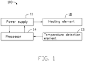
- an electronic cigarette temperature control system 100 which includes a power supply 11, a heating element 12, a temperature detection element 13 and a processor 14.
- the power supply 11 can be electrically coupled to the heating element 12 and the processor 14.
- the temperature detection element 13 can be electrically coupled to the processor 14.
- the heating element 12 can heat smoke liquid, wax, or tobacco to generate vapor, causing a user to experience a simulation of tobacco smoking after the power supply 11 supplies power to the heating element 12.
- the temperature detection element 13 is configured to detect a change of a temperature T of the heating element 12.
- the temperature t of the temperature detection element 13 will increase as the temperature T of the heating element 12 increases, to make a change of an associated physical quantity x of the temperature detection element 13, and the processor 14 can detect the associated physical quantity x and calculate the temperature T of the heating element 12 according to the associated physical quantity x.
- the temperature detection element 13 is arranged in an electronic cigarette.
- the temperature detection element 13 can be arranged to be adjacent to the heating element 12.
- the temperature detection element 13 can be selected from one of a group comprising of a positive temperature coefficient (PTC) thermistor, a negative temperature coefficient (NTC) thermistor, a bimetallic strip, a thermocouple, a quartz crystal temperature sensor, an optical fiber temperature sensor, an infrared temperature sensor, a P-N junction temperature sensor, and any combination thereof.
- the number of the temperature detection elements 13 can be one, two, or more than two. If space allows, a number of temperature detection elements 13 of one kind and/or of different kinds can be arranged at different positions of the electronic cigarette.
- the temperature T of the heating element 12 can be calculated according to the temperatures sensed by each of the temperature detection elements 13, and then an average value of the temperature of the heating element 12 can be calculated.
- the average value of the temperature of the heating element 12 can more accurately reflect the actual temperature T of the heating element 12.
- the processor 14 can timely determine and eliminate unreliable data, thereby the electronic cigarette temperature control system 100 can work normally with a higher temperature control accuracy.
- the associated physical quantity x can be selected from one of a group consisting of a temperature t, a resistance, a voltage, a current, a resonant frequency, an optical power, and any combination thereof according to individual differences in the different detection elements of the temperature detection element 13.
- the processor 14 can determine the temperature t of the temperature detection element 13 according to the associated physical quantity x of the temperature detection element 13, and determine the temperature T of the heating element 12 according to the temperature t of the temperature detection element 13. The processor 14 can further compare the temperature T of the heating element 12 with an upper threshold of the operating temperature T H and a lower threshold of the operating temperature T L . An output voltage / an output power from the power supply 11 to the heating element 12 can be controlled accordingly.
- the temperature detection element 13 can be a PTC thermistor.
- the temperature t of the temperature detection element 13 can increase as the temperature T of the heating element 12 increases.
- the resistance value R T of the temperature detection element 13 can increase with the increasing of temperature t of the temperature detection element 13.
- the associated physical quantity x of the temperature detection element 13 can be a resistance value R T .
- the temperature detection element 13 can be coupled with a fixed resistor R 5 in series.
- a voltage drop across the fixed resistor R 5 can be (V e - Vf).
- a current flowing through the fixed resistor R 5 can be (V e - Vf) / R 5 .
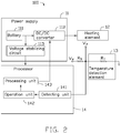
- the processor 14 can include a detecting unit 141, an operation unit 142, and a processing unit 143 coupled in sequence.
- the detecting unit 141 can be electrically coupled to the temperature detection element 13, to detect the voltage drop Vf across the temperature detection element 13, and output the voltage drop Vf to the operation unit 142.
- the operation unit 142 can pre-store a first formula, a relationship between the resistance value R T and the temperature t of the temperature detection element 13, and a second formula.
- the processing unit 143 can compare the temperature T of the heating element 12 with the pre-stored upper threshold of the operating temperature T H and the lower threshold of the operating temperature T L , and control the output voltage / the output power from the power supply 11 to the heating element 12 accordingly.
- the power supply 11 can include a battery 111, a DC/DC converter 112, and a voltage-stabilizing circuit 113.
- the battery 111 can be electrically coupled to the DC/DC converter 112 and the steady voltage circuit 113.
- the battery 111 can be charged with sufficient energy to power the DC/DC converter 112 and the voltage-stabilizing circuit 113.
- the DC/DC converter 112 can be electrically coupled to the heating element 12.
- the DC/DC converter 112 can boost a voltage from the battery 111 to the heating element 12.
- the voltage-stabilizing circuit 113 can be electrically coupled to the processor 14.
- the voltage-stabilizing circuit 113 can output a constant voltage V e to the processor 14.
- the battery 111 can be a lithium-ion battery. It will be appreciated that, in other embodiments, the DC/DC converter 112 and the voltage-stabilizing circuit 113 can be omitted, or be replaced by other circuits.
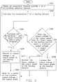
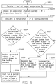
- the electronic cigarette temperature control system 100 of the invention includes the following steps in operation:
- the processor 14 can calculate the temperature T of the heating element 12 according to the associated physical quantity x of the temperature detection element 13. Then the procedure goes to step S103.
- the processor 14 can compare the temperature T of the heating element 12 with the upper threshold of the operating temperature T H and the lower threshold of the operating temperature T L . If the temperature T of the heating element 12 is greater than the upper threshold of the operating temperature T H , the procedure goes to step S104. If the temperature T of the heating element 12 is less than the lower threshold of the operating temperature T L , the procedure goes to step S106.
- step S104 the processor 14 can control the power supply 11 to reduce the output voltage / the output power to the heating element 12. Then the procedure goes to step S105.
- the heating element 12 can work for a period at the adjusted output voltage / the adjusted output power. Then, the procedure goes back to step S101, and repeats the subsequent processing. In the illustrated embodiment, the period can be one second.
- the processor 14 can determine whether the output voltage / the output power from the power supply 11 to the heating element 12 reaches a maximum output voltage / output power.
- step S107 If the output voltage / the output power from the power supply 11 to the heating element 12 reaches the maximum output voltage / output power, the procedure goes to step S107. If the output voltage / the output power from the power supply 11 to the heating element 12 has not yet reached the maximum output voltage / output power, the procedure goes to step S108.
- step S107 the processor 14 can control the power supply 11 to maintain the output voltage / the output power to the heating element 12. Then the procedure goes to step S105.
- step S108 the processor 14 can control the power supply 11 to increase the output voltage / the output power to the heating element 12. Then the procedure goes to step S105.
- the electronic cigarette temperature control system 100 can further include a display.
- the display can be configured to display information about work state of the electronic cigarette, such as, a temperature T of the heating element, a battery power, a work voltage, an output power, or the like.
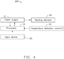
- an electronic cigarette temperature control system 200 is provided.
- the electronic cigarette temperature control system 200 of the second embodiment can be similar to the electronic cigarette temperature control system 100 of the first embodiment, except that:
- the electronic cigarette temperature control system 200 can further include an input device 25 electrically coupled to the processor 14.
- the user can input a desired target temperature T D (T L ⁇ T D ⁇ T H ) via the input device 25.
- the heating element 12 can be maintained to work at a temperature T D ⁇ ⁇ t' under the control of the processor 14.
- ⁇ t' represents a temperature deviation, which is generated by a certain lag of a response time of the power supply 11, the heating element 12, the temperature detection element 13, and the processor 14.
- the electronic cigarette temperature control method 200 of the invention includes the following steps in operation:
- the processor 14 can receive a desired target temperature T D (T L ⁇ T D ⁇ T H ) inputted from the user via the input device 25. Then the procedure goes to step S202.
- step S202 the processor 14 can obtain the associated physical quantity x of the temperature detection element 13. Then the procedure goes to step S203.
- step S203 the processor 14 can calculate the temperature T of the heating element 12. Then the procedure goes to step S204.
- the processor 14 can compare the temperature T of the heating element 12 with the desired target temperature T D . If the temperature T of the heating element 12 is greater than the desired target temperature T D , the procedure goes to step S205. If the temperature T of the heating element 12 is less than the desired target temperature T D , the procedure goes to step S207.
- step S205 the processor 14 can control the power supply 11 to reduce the output voltage / the output power to the heating element 12. Then the procedure goes to step S206.
- the heating element 12 can work for a period at the adjusted output voltage / the adjusted output power, then the procedure goes to step S202, and repeats the subsequent processing.
- the period can be one second.
- the processor 14 can determine whether the output voltage / the output power from the power supply 11 to the heating element 12 reaches a maximum output voltage / output power. If the output voltage / the output power from the power supply 11 to the heating element 12 reaches the maximum output voltage / output power, the procedure goes to step S208. If the output voltage / the output power from the power supply 11 to the heating element 12 has not yet reached the maximum output voltage / output power, the procedure goes to step S209.
- step S208 the processor 14 can control the power supply 11 to maintain the output voltage / the output power to the heating element 12. Then the procedure goes to step S206.
- the processor 14 can control the power supply 11 to increase the output voltage / the output power to the heating element 12. Then the procedure goes to step S206.
- the steps of the electronic cigarette temperature control method of the second embodiment can be the same as the electronic cigarette temperature control method of the first embodiment.
- the electronic cigarette temperature control system 200 can further include a display.
- the display can be configured to display information about work state of the electronic cigarette, such as, a temperature T of the heating element, a battery power, a work voltage, an output power, or the like.
- the electronic cigarette temperature control system 300 can include a power supply 31, a thermostatic switch 36, and a heating element 32 coupled in sequence.
- the heating element 32 can heat smoke liquid, wax, or tobacco, causing a user to experience a simulation of tobacco smoking after the power supply 31 supplies power to the heating element 32.
- the thermostatic switch 36 can turn on a connection between the power supply 31 and the heating element 32 or turn off the connection between the power supply 31 and the heating element 32 in the role of temperature.
- the temperature t s of the thermostatic switch 36 can increase when the temperature T of the heating element 32 increases.
- the thermostatic switch 36 can turn on the connection between the power supply 31 and the heating element 32.
- the heating element 32 can work normally.
- the temperature T of the heating element 32 can increase and the temperature t s of the thermostatic switch 36 can increase accordingly.
- the thermostatic switch 36 can turn off the connection between the power supply 31 and the heating element 32.
- the heating element 32 can stop working.
- the temperature T of the heating element 32 can naturally decrease and the temperature t s of the thermostatic switch 36 can decrease accordingly until that the temperature t s of the thermostatic switch 36 is less than the switch temperature T M of the thermostatic switch 36.
- the thermostatic switch 36 can turn on the connection between the power supply 31 and the heating element 32 again, thus the heating element 32 can work normally again.
- the thermostatic switch 36 can be arranged in the electronic cigarette. Preferably, the thermostatic switch 36 can be arranged to be adjacent to the heating element 32. Considering that the temperature t s of the thermostatic switch 36 is slightly less than the temperature T of the heating element 32, preferably, the switching temperature T M of the thermostatic switch 36 is slightly less than the upper threshold of the operating temperature T H .
- the thermostatic switch 36 can be selected from one of a group consisting of a mechanical thermostat switch, an electronic thermostat switch, a temperature relay, and any combination thereof.
- the mechanical thermostat switch can be a vapor pressure thermostat switch, a liquid expansion thermostat switch, a gas adsorption thermostat switch, or a metal expansion thermostat switch.
- the metal expansion thermostat switch can be a bimetal switch or a memory alloy actuated heat switch.
- the electronic thermostat switch can be a resistance thermostat switch or a thermocouple thermostat switch.
- the temperature relay can be a thermal reed relay.
- the electronic cigarette temperature control system 300 can further include a display.
- the display can be configured to display information about work state of the electronic cigarette, such as, a temperature T of the heating element, a battery power, a work voltage, an output power, or the like.
- the electronic cigarette temperature control system 400 of the fourth embodiment can be similar to the electronic cigarette temperature control system 300 of the third embodiment, except that:
- the electronic cigarette temperature control system 400 can include a processor 44.
- the thermostatic switch 36 can be electrically coupled to the processor 44.
- the thermostatic switch 36 cannot control the connection between the power supply 31 and the heating element 32 directly.
- the processor 44 can control the output voltage / the output power from the power supply 31 to the heating element 32 after the processor 44 judges according to an on or off state of the thermostatic switch 36.
- the temperature t s of the thermostatic switch 36 can increase when the temperature T of the heating element 32 increases.
- the thermostatic switch 36 can perform action A.
- the thermostatic switch 36 can perform action B.
- the processor 44 can detect the action of the thermostatic switch 36, and control the output voltage / the output power from the power supply 41 to the heating element 32 according to the different action of the thermostatic switch 36.
- the action A can be the thermostatic switch 36 turn on and the action B can be the thermostatic switch 36 turn off. In other embodiments, the action A can be the thermostatic switch 36 turn off and the action B can be the thermostatic switch 36 turn on.
- the electronic cigarette temperature control system 400 has the following beneficial effects:
- the electronic cigarette temperature control system 400 of the invention includes the following steps in operation:
- the processor 44 can determine a relationship between the temperature t s of the thermostatic switch 36 and a switch temperature T M of the thermostatic switch 36 according to the action of the thermostatic switch 36.
- the procedure goes to step S402.
- the procedure goes to step S404.
- step S402 the processor 44 can control the power supply 31 to reduce the output voltage / the output power to the heating element 32. Then the procedure goes to step S403.
- the heating element 32 can work for a period at the adjusted output voltage / the adjusted output power. Then, the procedure goes to step S401, and repeats the subsequent processing. In the illustrated embodiment, the period can be one second.
- the processor 44 can determine whether the output voltage / the output power from the power supply 31 to the heating element 32 reaches a maximum output voltage / output power. If the output voltage / the output power from the power supply 31 to the heating element 32 reaches the maximum output voltage / output power, the procedure goes to step S405. If the output voltage / the output power from the power supply 31 to the heating element 32 doesn't reach the maximum output voltage / output power, the procedure goes to step S406.
- step S405 the processor 44 can control the power supply 31 to maintain the output voltage / the output power to the heating element 32. Then the procedure goes to step S403.
- step S406 the processor 44 can control the power supply 31 to increase the output voltage / the output power to the heating element 32. Then the procedure goes to step S403.
- the electronic cigarette temperature control system 400 can further include a display.
- the display can be configured to display information about work state of the electronic cigarette, such as, a temperature T of the heating element, a battery power, a work voltage, an output power, or the like.
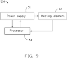
- the electronic cigarette temperature control system 500 can include a power supply 51, a heating element 52, and a processor 54.
- the power supply 51 can be electrically coupled to the heating element 52 and the processor 54.
- the heating element 52 can be electrically coupled to the processor 54.
- the heating element 52 can heat smoke liquid, wax, or tobacco, causing a user to experience a simulation of tobacco smoking after the power supply 51 supplies power to the heating element 52.
- the heating element 52 can act as the heating element and the temperature detection element.
- the heating element 52 has temperature coefficient of resistance characteristics wherein the resistance value R L of the heating element 52 increases with the increasing of the temperature T of the heating element 52.
- the heating element 52 can be made of material selected from one of a group consisting of platinum, copper, nickel, titanium, iron, ceramic-based PTC materials, polymer-based PTC materials, and any combination thereof.
- the processor 54 can pre-store an upper threshold of the operating temperature T H , a lower threshold of the operating temperature T L , and a relationship between the resistance value R L of the heating element 52 and the temperature T of the heating element 52.
- the processor 54 can determine the temperature T of the heating element 52 according to the resistance value R L of the heating element 52.
- the processor 54 can further compare the temperature T of the heating element 52 with the upper threshold of the operating temperature T H and the lower threshold of the operating temperature T L , and control the output voltage / the output power from the power supply 51 to the heating element 52 accordingly.
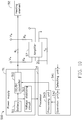
- the power supply 51 can include a battery 511, a DC/DC converter 512, and a voltage-stabilizing circuit 513.
- the battery 511 can be electrically coupled to the DC/DC converter 512 and the voltage-stabilizing circuit 513.
- the battery 511 can be charged with sufficient energy to power the DC/DC converter 512 and the voltage-stabilizing circuit 513.
- the voltage-stabilizing circuit 513 can be electrically coupled to the processor 54.
- the voltage-stabilizing circuit 513 can output a constant voltage to the processor 54.
- the battery 511 can be a lithium-ion battery. It will be appreciated that, in other embodiments, the DC/DC converter 512 and the voltage-stabilizing circuit 513 can be omitted, or be replaced by other circuits.
- the electronic cigarette temperature control system 500 can further include a first fixed resistor R 1 .
- the first fixed resistor R 1 can be arranged between the power supply 51 and the heating element 52.
- the first fixed resistor R 1 can be configured to auxiliarily calculate the resistance value R L of the heating element 52.
- the first fixed resistor R 1 can be arranged between the DC/DC converter 512 and the heating element 52.
- the DC/DC converter 512 can be controlled by the processor 54 to provide a constant voltage V a to the first fixed resistor R 1 and the heating element 52.
- the voltage drop across the heating element 52 can be V b .
- the current flowing through the heating element 52 can be (V a -V b ) / R 1
- the resistance value R L of the heating element 52 can be R 1 *V b /(V a -V b ).
- the electronic cigarette temperature control system 500 can further include a second fixed resistor R 2 , an amplifier 57, a third fixed resistor R 3 , and a fourth fixed resistor R 4 .
- the first fixed resistor R 1 can be coupled in parallel to a series connection of the second fixed resistor R 2 , the amplifier 57, the third fixed resistor R 3 .
- the fourth fixed resistor R 4 can be coupled with the amplifier 57 in parallel.
- the amplifier 57 can be a LT6105 chip.
- connection between the second fixed resistor R 2 , the third fixed resistor R 3 , and the fourth fixed resistor R 4 can be different according to the different amplifier 57, at least one of the second fixed resistor R 2 , the third fixed resistor R 3 , and the fourth fixed resistor R 4 may be omitted, or other electronic components may be added.
- the processor 54 can include a detecting unit 541, an operation unit 542, and a processing unit 543 coupled in sequence.
- the detecting unit 541 can be electrically coupled to the fourth fixed resistor R 4 .
- the detecting unit 541 can be configured to detect the voltage drop V c across the fourth fixed resistor R 4 and output the voltage drop V c to the operation unit 542.
- the operation unit 542 can pre-store a third formula, a fourth formula, and a relationship between the resistance value R L of the heating element 52 and the temperature T of the heating element 52.
- the operation unit 542 can calculate the voltage drop (V a - V b ) across the first fixed resistor R 1 according to the third formula based on characteristic parameter of the amplifier 57, and calculate the resistance value R L of the heating element 52 according to the fourth formula.
- the operation unit 542 can further determine the temperature T of the heating element 52 according to the pre-stored relationship between the resistance value R L of the heating element 52 and the temperature T of the heating element 52, and output the temperature T of the heating element 52 to the processing unit 543.
- the processing unit 543 can compare the temperature T of the heating element 52 with the pre-store upper threshold of the operating temperature T H and the lower threshold of the operating temperature T L , and control the output voltage / the output power from the DC/DC converter 512 to the heating element 52 accordingly.
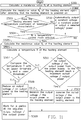
- the electronic cigarette temperature control system 500 of the invention includes the following steps in operation:
- the processor 54 can calculate the resistance value R L of the heating element 52 before the heating element 52 is powered on. Then the procedure goes to step S502.
- the processor 54 can calculate the resistance value R L of the heating element 52 again after the processor 54 detects that the heating element 52 is powered on. Then the procedure goes to step S503.
- the processor 54 can determine whether the heating element 52 has temperature coefficient of resistance characteristics according to the resistance value R L calculated at step S501 and the resistance value R L calculated at step S502. If a difference between the resistance value R L calculated at step S501 and the resistance value R L calculated at step S502 is out of a preset range, the heating element 52 can have temperature coefficient of resistance characteristics, the procedure goes to step S504. If the difference between the resistance value R L calculated at step S501 and the resistance value R L calculated at step S502 is no significant or is in the preset range, the heating element 52 doesn't have temperature coefficient of resistance characteristics, the procedure goes to step S510.
- the processor 54 can determine whether a temperature control mode is selected. If the processor 54 determines that the temperature control mode is selected, the procedure goes to step S505. If the processor 54 determines that the temperature control mode is not selected, the procedure goes to step S510.
- step S505 the processor 54 can calculate the resistance value R L of the heating element 52. Then the procedure goes to step S506.
- the processor 54 can calculate the temperature T of the heating element 52 according to the resistance value R L of the heating element 52. Then the procedure goes to step S507.
- the processor 54 can compare the temperature T of the heating element 52 with the upper threshold of the operating temperature T H and the lower threshold of the operating temperature T L . If the temperature T of the heating element 52 is greater than the upper threshold of the operating temperature T H , the procedure goes to step S508. If the temperature T of the heating element 52 is less than the lower threshold of the operating temperature T L , the procedure goes to step S511.
- step S508 the processor 54 can control the power supply 51 to reduce the output voltage / the output power to the heating element 52. Then the procedure goes to step S509.
- the heating element 52 can work for a period at the adjusted output voltage / the adjusted output power. Then, the procedure goes to step S505, and repeats the subsequent processing. In the illustrated embodiment, the period can be one second.
- the processor 54 can automatically control the power supply 51 to output a constant voltage / a constant power to the heating element 52, or the processor 54 can control the power supply 51 to output a selected voltage/ a selected output power to the heating element 52.
- the processor 54 can determine whether the output voltage / the output power from the power supply 51 to the heating element 52 reaches a maximum output voltage / output power. If the output voltage / the output power from the power supply 51 to the heating element 52 reaches the maximum output voltage / output power, the procedure goes to step S512. If the output voltage / the output power from the power supply 51 to the heating element 52 doesn't reach the maximum output voltage / output power, the procedure goes to step S513.
- step S512 the processor 54 can control the power supply 51 to maintain the output voltage / the output power to the heating element 52. Then the procedure goes to step S509.
- step S513 the processor 54 can control the power supply 51 to increase the output voltage / the output power to the heating element 52. Then the procedure goes to step S509.
- the electronic cigarette temperature control system 500 can further include a display.
- the display can be configured to display information about work state of the electronic cigarette, such as, a temperature T of the heating element, a battery power, a work voltage, an output power, or the like.
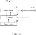
- the electronic cigarette temperature control system 600 of the sixth embodiment can be similar to the electronic cigarette temperature control system 500 of the fifth embodiment, except that:
- the electronic cigarette temperature control system 600 can further include an input device 65 electrically coupled to the processor 54.
- the user can input a desired target temperature T D via the input device 65.
- the desired target temperature T D is greater than or equal to the lower threshold of the operating temperature T L and is less than or equal to the upper threshold of the operating temperature T H .
- the heating element 52 can be controlled by the processor 54 to maintain to work at a temperature T D ⁇ ⁇ t'. Where ⁇ t' represents a temperature deviation generated by a certain lag of a response time of the power supply 51, the heating unit 52, and the processor 54.
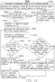
- the electronic cigarette temperature control system 600 of the invention includes the following steps in operation:
- step S601 the processor 54 can calculate the resistance value R L of the heating element 52 before the heating element 52 is powered on. Then the procedure goes to step S602.
- the processor 54 can calculate the resistance value R L of the heating element 52 again after the processor 54 detects that the heating element 52 is powered on. Then the procedure goes to step S603.
- the processor 54 can determine whether the heating element 52 has temperature coefficient of resistance characteristics according to the resistance value R L calculated at step S601 and the resistance value R L calculated at step S602. If a difference between the resistance value R L calculated at step S601 and the resistance value R L calculated at step S602 is out of a preset range, the heating element 52 has temperature coefficient of resistance characteristics, the procedure goes to step S604. If the difference between the resistance value R L calculated at step S601 and the resistance value R L calculated at step S602 is no significant or is in a preset range, the heating element 52 doesn't have temperature coefficient of resistance characteristics, the procedure goes to step S610.
- the processor 54 can receive a desired target temperature T D (T L ⁇ T D ⁇ T H ) inputted from the user via the input device 65. Then the procedure goes to step S605.
- step S605 the processor 54 can calculate the resistance value R L of the heating element 52. Then the procedure goes to step S606.
- the processor 54 can calculate the temperature T of the heating element 52 according to the resistance value R L of the heating element 52. Then the procedure goes to step S607.
- the processor 54 can compare the temperature T of the heating element 52 with the desired temperature T D . If the temperature T of the heating element 52 is greater than the desired temperature T D , the procedure goes to step S608. If the temperature T of the heating element 52 is less than the desired temperature T D , the procedure goes to step S611.
- step S608 the processor 54 can control the power supply 51 to reduce the output voltage / the output power to the heating element 52. Then the procedure goes to step S609.
- the heating element 52 can work for a period at the adjusted output voltage / the adjusted output power. Then, the procedure goes to step S605, and repeats the subsequent processing. In the illustrated embodiment, the period can be one second.
- the processor 54 can automatically control the power supply 51 to output a constant voltage / a constant power to the heating element 52, or the processor 54 can control the power supply 51 to output a selected voltage/ a selected power to the heating element 52.
- the processor 54 can determine whether the output voltage / the output power from the power supply 51 to the heating element 52 reaches a maximum output voltage / output power. If the output voltage / the output power from the power supply 51 to the heating element 52 reaches the maximum output voltage / output power, the procedure goes to step S612. If the output voltage / the output power from the power supply 51 to the heating element 52 doesn't reach the maximum output voltage / output power, the procedure goes to step S613.
- step S612 the processor 54 can control the power supply 51 to maintain the output voltage / the output power to the heating element 52. Then the procedure goes to step S609.
- step S613 the processor 54 can control the power supply 51 to increase the output voltage / the output power to the heating element 52. Then the procedure goes to step S609.
- the steps of the electronic cigarette temperature control method of the sixth embodiment can be the same as the electronic cigarette temperature control method of the fifth embodiment.
- the electronic cigarette temperature control system 600 can further include a display.
- the display can be configured to display information about work state of the electronic cigarette, such as, a temperature T of the heating element, a battery power, a work voltage, an output power, or the like.
- the electronic cigarette temperature control system 700 of the seventh embodiment can be similar to the electronic cigarette temperature control system 100 of the first embodiment, except that:
- the electronic cigarette temperature control system 700 can further include a thermostatic switch 76 coupled between the power supply 11 and the heating element 12.
- the thermostatic switch 76 can turn on a connection between the power supply 11 and the heating element 12 or turn off the connection between the power supply 11 and the heating element 12 at a role of temperature.
- the thermostatic switch 76 can be arranged in the electronic cigarette.
- the thermostatic switch 76 can be arranged to be adjacent to the heating element 12. Considering that the temperature t s of the thermostatic switch 76 is slightly less than the temperature T of the heating element 12, preferably, the switching temperature T M of the thermostatic switch 76 is slightly less than the upper threshold of the operating temperature T H .
- the thermostatic switch 76 can be selected from one of a group consisting of a mechanical thermostat switch, an electronic thermostat switch, a temperature relay, and any combination thereof.
- the mechanical thermostat switch can be a vapor pressure thermostat switch, a liquid expansion thermostat switch, a gas adsorption thermostat switch, or a metal expansion thermostat switch.
- the metal expansion thermostat switch can be a bimetal switch or a memory alloy actuated heat switch.
- the electronic thermostat switch can be a resistance thermostat switch or a thermocouple thermostat switch.
- the temperature relay can be a thermal reed relay.
- the steps of the electronic cigarette temperature control method carried out using the configurations of the electronic cigarette temperature control system 700 illustrated in FIG. 14 can be the same as the steps of the electronic cigarette temperature control method carried out using the configurations of the electronic cigarette temperature control system 100 of the first embodiment, thereby doesn't described again herein.
- the thermostatic switch 76 can turn off.
- the power supply 11 can stop powering the heating element 12.
- the temperature T of the heating element 12 can according naturally decrease and the temperature t s of the thermostatic switch 76 can decrease accordingly until that the temperature t s of the thermostatic switch 76 is less than the switch temperature T M of the thermostatic switch 76.
- the thermostatic switch 76 can turn on the connection between the power supply 11 and the heating element 12 again, thus the heating element 12 can work normally again as the first embodiment.
- the electronic cigarette can execute a double temperature control protection, especially when the temperature detection element 13 and/or the processor 14 is malfunctioned, the electronic cigarette can still control the temperature of heating element 12.
- the second embodiment can be varied with reference to the seventh embodiment, namely, the electronic cigarette temperature control system 200 can further include a thermostatic switch coupled between the power supply 21 and the heating element 22, thereby executing a double temperature control protection.
- the fifth embodiment and the sixth embodiment can be varied with reference to the seventh embodiment: the electronic cigarette temperature control system can further include a thermostatic switch coupled between the power supply and the heating element.
- the electronic cigarette of the fifth embodiment and the sixth embodiment can execute a double temperature control protection.
- the steps of the electronic cigarette temperature control method carried out using the configurations of the electronic cigarette temperature control system of the fifth embodiment and the sixth embodiment can be the same as the steps of the electronic cigarette temperature control method carried out using the configurations of the electronic cigarette temperature control system of the third embodiments, thereby doesn't described again herein.
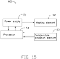
- an eighth embodiment of the electronic cigarette temperature control system 800 of the present disclosure is illustrated.
- the electronic cigarette temperature control system 800 of the eighth embodiment can be similar to the electronic cigarette temperature control system 500 of the fifth embodiment, except that:
- the electronic cigarette temperature control system 800 can further include a temperature detection element 83 electrically coupled to the processor 54.
- the electronic cigarette of the eighth embodiment can execute a temperature control as the fifth embodiment.
- the electronic cigarette of the eighth embodiment can execute a temperature control as the first embodiment.
- the electronic cigarette temperature control system 800 can further include a thermostatic switch electrically coupled to the processor.
- the electronic cigarette temperature control system 800 of the eighth embodiment can execute a temperature control as the fourth embodiment.
- the electronic cigarette temperature control system 800 can have the following beneficial effect:
- the electronic cigarette of the eighth embodiment can execute a temperature control as the fifth embodiment.
- the electronic cigarette of the eighth embodiment can execute a temperature control as the first embodiment.
- the electronic cigarette of the eighth embodiment can execute a temperature control as the fourth embodiment.
- the electronic cigarette temperature control system can further include a thermostatic switch coupled between the power supply 51 and the heating element 52 for executing a double temperature control protection. Especially, when the temperature detection element 83 and/or the processor 54 is malfunctioned, the electronic cigarette can still control the temperature of the heating element 52.
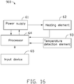
- the electronic cigarette temperature control system 900 of the ninth embodiment can be similar to the electronic cigarette temperature control system 600 of the sixth embodiment, except that:
- the electronic cigarette temperature control system 900 can further include a temperature detection element 93 electrically coupled to the processor 64.
- the heating element 62 has temperature coefficient of resistance characteristics
- the heating element 62 of the electronic cigarette temperature control system 900 of the ninth embodiment can be maintained to work at the temperature T D ⁇ ⁇ t' as the sixth embodiment.
- the heating element 62 doesn't have temperature coefficient of resistance characteristics
- the heating element 62 of the electronic cigarette temperature control system 900 of the ninth embodiment can be maintained to work at the temperature T D ⁇ ⁇ t' as the second embodiment.
- the electronic cigarette temperature control system 900 can further include a thermostatic switch coupled between the power supply 61 and the heating element 62, thereby executing a double temperature control protection.
- the electronic cigarette 10 can include a housing 101, a mouthpiece 102, a liquid tank 103, a liquid guiding component 104, and an electronic cigarette temperature control system 100.
- the electronic cigarette temperature control system 100 can have a liquid communication with the liquid tank 103 via the the liquid guiding component 104.
- the electronic cigarette temperature control system 100 can heat smoke liquid to generate vapor, and control the temperature of the heating element 12 within a reasonable range.
- the electronic cigarette temperature control system 100 can be replaced by any one from the electronic cigarette temperature control systems (200, 3000, 400, 500, 600, 700, 800, 900) of the second embodiment to the ninth embodiment, or replaced by the electronic cigarette temperature control system modified from the electronic cigarette temperature control system (100, 200, 3000, 400, 500, 600, 700, 800, 900) of the first embodiment to the ninth embodiment.
- any one from the electronic cigarette temperature control systems of the first embodiment to the ninth embodiment can be applied in any electronic cigarette, but is not limited to the liquid guiding manner, the atomization manner, the types of the aerosol formation matrix (for example, smoke liquid, or wax or tobacco), the heating manner, and the likes.
- any one from the electronic cigarette temperature control system modified from the electronic cigarette temperature control system of the first embodiment to the ninth embodiment can be applied in the any electronic cigarette, but is not limited to the liquid guiding manner, the atomization manner, the types of the aerosol formation matrix (for example, smoke liquid, or wax or tobacco), the heating manner, and the like.
Abstract
Description
- The subject matter herein generally relates to electronic cigarette technology, and particularly, to an electronic cigarette temperature control system and method, and an electronic cigarette with the same.
- Electronic cigarettes, also known as virtual cigarettes, have similar taste as conventional cigarettes, and are mainly used to simulate smoking without affecting health, for smoking cessation or replacing conventional cigarettes. However, with increasing of the output voltage or output power of a battery assembly of the electronic cigarette and decreasing of the resistance of a heating member of the atomizing device, the temperature generated by the heating member becomes higher. An excessive temperature of the heating member may lead the smoke liquid, the wax, or the tobacco to produce and release some substances which are harmful to health.
- The present disclosure provides an electronic cigarette temperature control system and method, and an electronic cigarette with the same for controlling the temperature of the heating element within a reasonable range.
- The technical solution to achieve the object of the present invention is as follows:
- An object of the present disclosure is to provide an electronic cigarette temperature control system which can include a power supply, a heating element, a temperature detection element, and a processor. The power supply can be electrically coupled to the heating element and the processor. The temperature detection element can be electrically coupled to the processor. The temperature detection element can be configured to detect a change of a temperature T of the heating element, and output the change of the temperature T of the heating element to the processor. The processor can be configured to determine the temperature t of the temperature detection element according to an associated physical quantity x of the temperature detection element, and calculate the temperature T of the heating element according to the temperature t of the temperature detection element.
- Furthermore, the temperature detection element can be selected from one of a group consisting of a positive temperature coefficient (PTC) thermistor, a negative temperature coefficient (NTC) thermistor, a bimetallic strip, a thermocouple, a quartz crystal temperature sensor, an optical fiber temperature sensor, an infrared temperature sensor, a P-N junction temperature sensor, and any combination thereof.
- Preferably, the temperature detection element can be arranged to be adjacent to the heating element.
- Furthermore, the processor can compare the temperature T of the heating element with an upper threshold of an operating temperature TH and a lower threshold of the operating temperature TL, and control the output voltage / the output power from the power supply to the heating element according to the result of comparison.
- Furthermore, the associated physical quantity x can be selected from one of a group consisting of a temperature t, a resistance, a voltage, a current, a resonant frequency, an optical power, and any combination thereof.
- Furthermore, the temperature detection element is a PTC thermistor, and the associated physical quantity x of the temperature detection element is a resistance value RT of the PTC thermistor.
- Furthermore, the electronic cigarette temperature control system can further include a fixed resistor R5 coupled with the temperature detection element in series. A voltage drop across the fixed resistor R5 is (Ve - Vf), a current flowing through the fixed resistor R5 is (Ve - Vf) / R5, voltage drop across the temperature detection element is Vf, and the resistance value RT of the temperature detection element can be expressed by RT = R5 * Vf/ (Ve - Vf).
- Furthermore, the processor can further include a detecting unit, an operation unit, and a processing unit coupled in sequence.
- The detecting unit can be electrically coupled to the temperature detection element. The detecting unit can be configured to detect the voltage drop Vf across the temperature detection element, and output the voltage drop Vf across the temperature detection element to the operation unit.
- The operation unit can pre-store a first formula, a relationship between the resistance value RT of the temperature detection element and the temperature t of the temperature detection element, and a second formula. The first formula is RT = R5 * Vf/ (Ve-Vf). The second formula is T=t+Δt. The operation unit can be configured to calculate the temperature T of the heating element according to the voltage drop Vf, the first formula, the relationship between the resistance value RT and the temperature t of the temperature detection element, and the second formula, and can further output the temperature T of the heating element to the processing unit.
- The processing unit can compare the temperature T of the heating element with the pre-stored the upper threshold of the operating temperature TH and the lower threshold of the operating temperature TL. The output voltage / the output power from the power supply to the heating element can be controlled accordingly.
- Furthermore, the electronic cigarette temperature control system can further include an input device electrically coupled to the processor. The input device can be configured to provide an interface for a user to input a desired target temperature TD. The desired target temperature TD can be greater than or equal to the lower threshold of the operating temperature TL and be less than or equal to the upper threshold of the operating temperature TH, that is TL≤TD≤TH.
- Furthermore, the electronic cigarette temperature control system can further include a thermostatic switch coupled between the power supply and the heating element. The thermostatic switch can still control the temperature of heating element when the temperature detection element and/or the processor malfunction.
- An object of the present disclosure is to provide an electronic cigarette temperature control system which can include a power supply, a thermostatic switch, and a heating element coupled in sequence. The switching temperature TM of the thermostatic switch can be less than an upper threshold of an operating temperature TH of the electronic cigarette temperature control system.
- Furthermore, the thermostatic switch can be selected from one of a group consisting of a mechanical thermostatic switch, an electronic thermostatic switch, a temperature relay, and any combination thereof.
- Furthermore, the mechanical thermostatic switch can be a vapor pressure thermostatic switch, a liquid expansion thermostatic switch, a gas adsorption thermostatic switch, or a metal expansion thermostatic switch. The electronic thermostatic switch can be a resistance thermostatic switch or a thermocouple thermostatic switch. The temperature relay can be a thermal reed relay.
- Furthermore, the temperature ts of the thermostatic switch can increase when the temperature T of the heating element increases. When the temperature ts of the thermostatic switch is less than a switch temperature TM of the thermostatic switch, the thermostatic switch can turn on a connection between the power supply and the heating element. The heating element can work normally. The temperature T of the heating element can increase accordingly. When the temperature ts of the thermostatic switch is greater than the switch temperature TM of the thermostatic switch, the thermostatic switch can turn off the connection between the power supply and the heating element. The heating element can stop working. The temperature T of the heating element can naturally decrease.
- Preferably, the thermostatic switch can be arranged to be adjacent to the heating element.
- An object of the present disclosure is to provide an electronic cigarette temperature control system which can include a power supply, a heating element, a processor, and a thermostatic switch. The processor can be electrically coupled to the power supply and the thermostatic switch. The heating element can be electrically coupled to the power supply. The thermostatic switch can be arranged to be adjacent to the heating element. The switching temperature TM of the thermostatic switch can be less than an upper threshold of an operating temperature TH of the electronic cigarette temperature control system.
- Furthermore, the thermostatic switch can be selected from one of a group consisting of a mechanical thermostatic switch, an electronic thermostatic switch, a temperature relay, and any combination thereof.
- Furthermore, the mechanical thermostatic switch can be a vapor pressure thermostatic switch, a liquid expansion thermostatic switch, a gas adsorption thermostatic switch, or a metal expansion thermostatic switch. The electronic thermostatic switch can be a resistance thermostatic switch or a thermocouple thermostatic switch. The temperature relay can be a thermal reed relay.
- Furthermore, the temperature ts of the thermostatic switch can increase when the temperature T of the heating element increases. When the temperature ts of the thermostatic switch is less than a switch temperature TM of the thermostatic switch, the thermostatic switch can perform action A. When the temperature ts of the thermostatic switch is greater than the switch temperature TM of the thermostatic switch, the thermostatic switch can perform action B. The processor can detect the action of the thermostatic switch, and control an output voltage / an output power from the power supply to the heating element according to the action of the thermostatic switch.
- Furthermore, action A can be the thermostatic switch turn on and action B can be the thermostatic switch turn off, and in other embodiments, the action A can be the thermostatic switch turn off and the action B can be the thermostatic switch turn on.
- Preferably, the thermostatic switch can be arranged to be adjacent to the heating element.
- An object of the present disclosure is to provide an electronic cigarette temperature control system which can include a power supply, a heating element, and a processor. The power supply can be electrically coupled to the heating element and the processor. The heating element can be electrically coupled to the processor. The heating element can have temperature coefficient of resistance characteristics. The heating element can directly act as a temperature detection element and output a change of a temperature T of the heating element to the processor.
- Furthermore, the heating element can be made of material selected from one of a group consisting of platinum, copper, nickel, titanium, iron, ceramic-based PTC materials, polymer-based PTC materials, and any combination thereof. The resistance value RL of the heating element increases with the temperature T of the heating element.
- Furthermore, the processor can determine the temperature T of the heating element according to the resistance value RL of the heating element. The processor can further compare the temperature T of the heating element with an upper threshold of an operating temperature TH and a lower threshold of an operating temperature TL. An output voltage / an output power from the power supply to the heating element can be controlled accordingly.
- Furthermore, the electronic cigarette temperature control system can further include a first fixed resistor R1 coupled between the power supply and the heating element. A voltage drop across the first fixed resistor R1 is (Va - Vb), a voltage drop across the heating element is Vb, a current flowing through the heating element is (Va - Vb) / R1, and the resistance value RL of the heating element is R1 * Vb / (Va - Vb).
- Furthermore, the electronic cigarette temperature control system can further include a second fixed resistor R2, an amplifier, a third fixed resistor R3, and a fourth fixed resistor R4. The first fixed resistor R1 can be coupled in parallel to a series connection of the second fixed resistor R2, the amplifier, the third fixed resistor R3. The fourth fixed resistor R4 can be coupled with the amplifier in parallel, and based on the application characteristics of the amplifier, the voltage drop (Va-Vb) across the first fixed resistor R1 is Vc * R2/ R4.
- Furthermore, the processor can include a detecting unit, an operation unit, and a processing unit coupled in sequence.
- The detecting unit can be electrically coupled to the fourth fixed resistor R4. The detecting unit can be configured to detect the voltage drop Vc across the fourth fixed resistor R4, and output the voltage drop Vc across the fourth fixed resistor R4 to the operation unit.
- The operation unit can pre-store a third formula: (Va - Vb) = Vc * R2 / R4, a fourth formula: RL = R1 * Vb / (Va - Vb), and a relationship between the resistance value RL of the heating element and the temperature T of the heating element. The operation unit can be configured to calculate the temperature T of the heating element according to the voltage drop Vc, the third formula, the fourth formula, and the relationship between the resistance value RL of the heating element and the temperature T of the heating element. The operation unit can be further configured to output the temperature T of the heating element to the processing unit.
- The processing unit can compare the temperature T of the heating element with the pre-stored an upper threshold of an operating temperature TH and a lower threshold of the operating temperature TL. The output voltage / the output power from the power supply to the heating element can be controlled accordingly.
- Furthermore, the electronic cigarette temperature control system can further include an input device coupled to the processor. The input device can be configured to provide an interface for a user to input a desired target temperature TD. The desired target temperature TD can be greater than or equal to the lower threshold of the operating temperature TL and be less than or equal to the upper threshold of the operating temperature TH, that is TL≤TD≤TH.
- Furthermore, the electronic cigarette temperature control system can further include a thermostatic switch coupled between the power supply and the heating element. The thermostatic switch can still control the temperature of heating element when the heating element and/or the processor malfunction.
- Furthermore, the electronic cigarette temperature control system can further include a temperature detection element electrically coupled to the processor or a thermostatic switch electrically coupled to the processor.
- Preferably, the temperature detection element or the thermostatic switch can be arranged to be adjacent to the heating element.
- An object of the present disclosure is to provide an electronic cigarette including any one of the above electronic cigarette temperature control systems.
- An object of the present disclosure is to provide an electronic cigarette temperature control method. The electronic cigarette temperature control method applied in an electronic cigarette temperature control system or an electronic cigarette, where the electronic cigarette temperature control system or the electronic cigarette includes a power supply, a heating element, a processor, and a temperature detection element. The electronic cigarette temperature control method can include:
- The processor can obtain associated physical quantity x of the temperature detection element.
- The processor can calculate the temperature T of the heating element according to the associated physical quantity x of the temperature detection element.
- The processor can compare the temperature T of the heating element with an upper threshold of an operating temperature TH and a lower threshold of the operating temperature TL.
- The processor can adjust an output voltage / an output power from the power supply to the heating element according to the result of the comparison.
- The heating element can work for a period at the adjusted output voltage / the adjusted output power.
- Furthermore, the step "the processor can adjust an output voltage / an output power from the power supply to the heating element according to the result of the comparison" can include:
- The processor can control the power supply to reduce the output voltage / the output power to the heating element when the temperature T of the heating element is greater than the upper threshold of the operating temperature TH.
- Furthermore, the step "the processor can adjust an output voltage / an output power from the power supply to the heating element according to the result of the comparison" can include:
- The processor controlling the power supply to maintain the output voltage / the output power to the heating element when the temperature T of the heating element is less than a lower threshold of the operating temperature TL and the output voltage / the output power from the power supply to the heating element reaches a maximum output voltage / output power.
- Furthermore, the step "the processor can adjust an output voltage / an output power from the power supply to the heating element according to the result of the comparison" can include:
- The processor controlling the power supply to increase the output voltage / the output power to the heating element when the temperature T of the heating element is less than a lower threshold of the operating temperature TL and the output voltage / the output power from the power supply to the heating element has not yet reached a maximum output voltage / output power.
- Furthermore, the electronic cigarette temperature control system or the electronic cigarette can further include an input device. The electronic cigarette temperature control method can further include:
- Receiving a target temperature TD inputted by a user via the input device before the processor obtains the associated physical quantity x of the temperature detection element. The desired target temperature TD may be greater than or equal to the lower threshold of the operating temperature TL and may be less than or equal to the upper threshold of the operating temperature TH. The desired target temperature TD can replace the pre-stored upper threshold of the operating temperature TH and the pre-stored lower threshold of the operating temperature TL. The processor comparing the temperature T of the heating element with the desired target temperature TD.
- An object of the present disclosure is to provide an electronic cigarette temperature control method. The electronic cigarette temperature control method can be applied in an electronic cigarette temperature control system or an electronic cigarette. The electronic cigarette temperature control system or the electronic cigarette can include a power supply, a heating element, and a thermostatic switch. The electronic cigarette temperature control method can include:
- The thermostatic switch can determine the relationship between a temperature ts of the thermostatic switch and a switch temperature TM of the thermostatic switch.
- The thermostatic switch turning on a connection between the power supply and the heating element when the temperature ts of the thermostatic switch is less than the switch temperature TM of the thermostatic switch. The heating element accordingly works normally, the temperature T of the heating element accordingly increasing; and
- The thermostatic switch turning off the connection between the power supply and the heating element when the temperature ts of the thermostatic switch is greater than the switch temperature TM of the thermostatic switch. In this case, the heating element stops working, and the temperature T of the heating element naturally decreases.
- An object of the present disclosure is to provide an electronic cigarette temperature control method. The electronic cigarette temperature control method can be applied in an electronic cigarette temperature control system or an electronic cigarette. The electronic cigarette temperature control system or the electronic cigarette can include a power supply, a heating element, a processor, and a thermostatic switch. The electronic cigarette temperature control method can include:
- The processor can determine the relationship between a temperature ts of the thermostatic switch and a switch temperature TM of the thermostatic switch based on the action of the thermostatic switch, where the thermostatic switch performing action A when the temperature ts of the thermostatic switch is less than the switch temperature TM of the thermostatic switch, the thermostatic switch performing action B when the temperature ts of the thermostatic switch is greater than the switch temperature TM of the thermostatic switch. Where the action A is the thermostatic switch turn on and the action B is the thermostatic switch turn off, and in other embodiments, the action A can be the thermostatic switch turn off and the action B can be the thermostatic switch turn on.
- The processor can adjust an output voltage / an output power from the power supply to the heating element according to the action of the thermostatic switch.
- The heating element can work for a period at the adjusted output voltage / the adjusted output power.
- Furthermore, the step "the processor adjusting an output voltage / an output power from the power supply to the heating element according to the action of the thermostatic switch" can include:
- The processor controlling the power supply to reduce the output voltage / the output power to the heating element when the thermostatic switch performs action B.
- Furthermore, the step "the processor adjusting an output voltage / an output power from the power supply to the heating element according to the action of the thermostatic switch" can include:
- The processor controlling the power supply to maintain the output voltage / the output power to the heating element when the thermostatic switch performs action A and the output voltage / the output power from the power supply to the heating element reaches a maximum output voltage / output power.
- Furthermore, the step "the processor adjusting an output voltage / an output power from the power supply to the heating element according to the action of the thermostatic switch" can include:
- The processor controlling the power supply to increase the output voltage / the output power to the heating element when the thermostatic switch performs action A and the output voltage / the output power from the power supply to the heating element is less than a maximum output voltage / output power.
- An object of the present disclosure is to provide an electronic cigarette temperature control method. The electronic cigarette temperature control method can be applied in an electronic cigarette temperature control system or an electronic cigarette. The electronic cigarette temperature control system or the electronic cigarette can include a power supply, a heating element, and a processor. The electronic cigarette temperature control method can include:
- The processor calculating a resistance value RL of the heating element before the heating element is powered on;
- The processor calculating the resistance value RL of the heating element again after the processor detects that the heating element is powered on.
- The processor determining whether the heating element has temperature coefficient of resistance characteristics.
- The processor determining whether a temperature control mode is selected.
- The processor calculating the resistance value RL of the heating element.
- The processor calculating the temperature T of the heating element according to the resistance value RL of the heating element.
- The processor comparing the temperature T of the heating element with a pre-stored upper threshold of an operating temperature TH and a pre-stored lower threshold of the operating temperature TL.
- The processor adjusting an output voltage / an output power from the power supply to the heating element according to the result of the comparison.
- The heating element working for a period at the adjusted output voltage / the adjusted output power.
- Furthermore, the step "the processor determining whether the heating element has temperature coefficient of resistance characteristics" can include:
- The processor automatically controlling the power supply to output a constant voltage / a constant power to the heating element or the processor controlling the power supply to output a selected voltage/ a selected power to the heating element when the heating element doesn't have temperature coefficient of resistance characteristics; and
- The processor determining whether a temperature control mode is selected when the heating element has temperature coefficient of resistance characteristics.
- Furthermore, the step "the processor determining whether a temperature control mode is selected" can include:
- The processor automatically controlling the power supply to output a constant voltage / a constant power to the heating element or the processor controlling the power supply to output a selected voltage/ a selected power to the heating element when the temperature control mode is not selected; and
- The processor calculating the resistance value RL of the heating element when the temperature control mode is selected.
- Furthermore, the step "the processor adjusting an output voltage / an output power from the power supply to the heating element according to the result of the comparison" can include:
- The processor controlling the power supply to reduce the output voltage / the output power to the heating element when the temperature T of the heating element is greater than the upper threshold of the operating temperature TH.
- Furthermore, the step "the processor adjusting an output voltage / an output power from the power supply to the heating element according to the result of the comparison" can include:
- The processor controlling the power supply to maintain the output voltage / the output power to the heating element when the temperature T of the heating element is less than the lower threshold of the operating temperature TL and the output voltage / the output power from the power supply to the heating element reaches a maximum output voltage / output power.
- Furthermore, the step "the processor adjusting an output voltage / an output power from the power supply to the heating element according to the result of the comparison" can include:
- The processor controlling the power supply to increase the output voltage / the output power to the heating element when the temperature of the heating element is less than the lower threshold of the operating temperature TL and the output voltage / the output power from the power supply to the heating element is less than a maximum output voltage / output power.
- An object of the present disclosure is to provide an electronic cigarette executing any one of the above electronic cigarette temperature control method.
- The disclosure brings about the following beneficial effects:
- The electronic cigarette temperature control system and method, and the electronic cigarette with the same can maintain the temperature of the heating element at a reasonable range, avoiding the production and release of harmful substances. Thus, the electronic cigarette can maintain a good taste, save energy, avoid overheating of the housing of the electronic cigarette, and prevent thermal ageing of the inner components of the electronic cigarette.
- The addition of an input device allows the user to set the operating temperature of the heating element according to a need.
- The electronic cigarette can execute a double temperature control protection via adding the thermostatic switch coupled between the power supply and the heating element. This is especially important when the temperature detection element and/or the processor malfunction, as the electronic cigarette can still control the temperature of the heating element.
- The user can employ the heating element of the atomizer assembly portion which has or doesn't have temperature coefficient of resistance characteristics to execute the temperature control via adding the temperature detection element / the thermostatic switch and the processor. Thus, greater versatility is presented by the electronic cigarette temperature control system and the electronic cigarette.
-
-
FIG. 1 illustrates a circuit schematic diagram of a first embodiment of an electronic cigarette temperature control system. -
FIG. 2 illustrates a detailed circuit schematic diagram of the first embodiment of the electronic cigarette temperature control system. -
FIG. 3 illustrates a flowchart of a first embodiment of an electronic cigarette temperature control method. -
FIG. 4 illustrates a circuit schematic diagram of a second embodiment of the electronic cigarette temperature control system. -
FIG. 5 illustrates a flowchart of a second embodiment of the electronic cigarette temperature control method. -
FIG. 6 illustrates a circuit schematic diagram of a third embodiment of the electronic cigarette temperature control system. -
FIG. 7 illustrates a circuit schematic diagram of a fourth embodiment of the electronic cigarette temperature control system. -
FIG. 8 illustrates a flowchart of a fourth embodiment of the electronic cigarette temperature control method. -
FIG. 9 illustrates a circuit schematic diagram of a fifth embodiment of the electronic cigarette temperature control system. -
FIG. 10 illustrates a detailed circuit schematic diagram of the fifth embodiment of the electronic cigarette temperature control system. -
FIG. 11 illustrates a flowchart of a fifth embodiment of the electronic cigarette temperature control method. -
FIG. 12 illustrates a circuit schematic diagram of a sixth embodiment of the electronic cigarette temperature control system. -
FIGs. 13 illustrate a flowchart of a sixth embodiment of the electronic cigarette temperature control method. -
FIG. 14 illustrates a circuit schematic diagram of a seventh embodiment of the electronic cigarette temperature control system. -
FIG. 15 illustrates a circuit schematic diagram of an eighth embodiment of the electronic cigarette temperature control system. -
FIG. 16 illustrates a circuit schematic diagram of a ninth embodiment of the electronic cigarette temperature control system. -
FIG. 17 illustrates a circuit schematic diagram of a tenth embodiment of the electronic cigarette temperature control system. - The present disclosure will be described in detail with reference to the accompanying drawings in order to provide a clearer understanding of the technical features, objects and effects of the present invention. Obviously, the described embodiments are part of the present disclosure, but not all embodiments. Based on the embodiments of the present disclosure, all other embodiments obtained by others who skilled in the art without making creative work are within the scope of the present invention.
- Referring to
FIG. 1 , an electronic cigarettetemperature control system 100 is provided, which includes apower supply 11, aheating element 12, atemperature detection element 13 and aprocessor 14. Thepower supply 11 can be electrically coupled to theheating element 12 and theprocessor 14. Thetemperature detection element 13 can be electrically coupled to theprocessor 14. Theheating element 12 can heat smoke liquid, wax, or tobacco to generate vapor, causing a user to experience a simulation of tobacco smoking after thepower supply 11 supplies power to theheating element 12. - The
temperature detection element 13 is configured to detect a change of a temperature T of theheating element 12. The temperature t of thetemperature detection element 13 will increase as the temperature T of theheating element 12 increases, to make a change of an associated physical quantity x of thetemperature detection element 13, and theprocessor 14 can detect the associated physical quantity x and calculate the temperature T of theheating element 12 according to the associated physical quantity x. - The
temperature detection element 13 is arranged in an electronic cigarette. Preferably, thetemperature detection element 13 can be arranged to be adjacent to theheating element 12. Thetemperature detection element 13 can be selected from one of a group comprising of a positive temperature coefficient (PTC) thermistor, a negative temperature coefficient (NTC) thermistor, a bimetallic strip, a thermocouple, a quartz crystal temperature sensor, an optical fiber temperature sensor, an infrared temperature sensor, a P-N junction temperature sensor, and any combination thereof. The number of thetemperature detection elements 13 can be one, two, or more than two. If space allows, a number oftemperature detection elements 13 of one kind and/or of different kinds can be arranged at different positions of the electronic cigarette. On one hand, the temperature T of theheating element 12 can be calculated according to the temperatures sensed by each of thetemperature detection elements 13, and then an average value of the temperature of theheating element 12 can be calculated. The average value of the temperature of theheating element 12 can more accurately reflect the actual temperature T of theheating element 12. On the other hand, when one of thetemperature detection elements 13 is malfunctioning, theprocessor 14 can timely determine and eliminate unreliable data, thereby the electronic cigarettetemperature control system 100 can work normally with a higher temperature control accuracy. - The associated physical quantity x can be selected from one of a group consisting of a temperature t, a resistance, a voltage, a current, a resonant frequency, an optical power, and any combination thereof according to individual differences in the different detection elements of the
temperature detection element 13. - The
processor 14 can determine the temperature t of thetemperature detection element 13 according to the associated physical quantity x of thetemperature detection element 13, and determine the temperature T of theheating element 12 according to the temperature t of thetemperature detection element 13. Theprocessor 14 can further compare the temperature T of theheating element 12 with an upper threshold of the operating temperature TH and a lower threshold of the operating temperature TL. An output voltage / an output power from thepower supply 11 to theheating element 12 can be controlled accordingly. - Referring also to
FIG. 2 , in the illusrtated embodiment, thetemperature detection element 13 can be a PTC thermistor. The temperature t of thetemperature detection element 13 can increase as the temperature T of theheating element 12 increases. The resistance value RT of thetemperature detection element 13 can increase with the increasing of temperature t of thetemperature detection element 13. In the illustrated embodiment, the associated physical quantity x of thetemperature detection element 13 can be a resistance value RT. - Furthermore, in order for convenient measurement of the resistance value RT of the
temperature detection element 13, thetemperature detection element 13 can be coupled with a fixed resistor R5 in series. A voltage drop across the fixed resistor R5 can be (Ve - Vf). Thus, a current flowing through the fixed resistor R5 can be (Ve - Vf) / R5. A voltage drop across thetemperature detection element 13 can be Vf, thus the resistance value RT of thetemperature detection element 13 can be expressed by RT = R5 * Vf/ (Ve - Vf). - In detail, the
processor 14 can include a detectingunit 141, anoperation unit 142, and aprocessing unit 143 coupled in sequence. The detectingunit 141 can be electrically coupled to thetemperature detection element 13, to detect the voltage drop Vf across thetemperature detection element 13, and output the voltage drop Vf to theoperation unit 142. Theoperation unit 142 can pre-store a first formula, a relationship between the resistance value RT and the temperature t of thetemperature detection element 13, and a second formula. The first formula can be RT = R5 ∗ Vf/ (Ve - Vf). The second formula can be T=t+Δ t, where Δ t can be an experimental data presenting the difference between the temperature of theheating element 12 and the temperature of thetemperature detection element 13. Theoperation unit 142 can calculate the resistance value RT of thetemperature detection element 13 according to the first formula RT=R5 ∗ Vf/ (Ve - Vf), and calculate the temperature t of thetemperature detection element 13 according to the relationship between the resistance value RT of thetemperature detection element 13 and the temperature t of thetemperature detection element 13. Theoperation unit 142 can further calculate the temperature T of theheating element 12 according to the second formula T=t+Δ t, and output the temperature T of theheating element 12 to theprocessing unit 143. Theprocessing unit 143 can compare the temperature T of theheating element 12 with the pre-stored upper threshold of the operating temperature TH and the lower threshold of the operating temperature TL, and control the output voltage / the output power from thepower supply 11 to theheating element 12 accordingly. - Furthermore, the
power supply 11 can include abattery 111, a DC/DC converter 112, and a voltage-stabilizingcircuit 113. Thebattery 111 can be electrically coupled to the DC/DC converter 112 and thesteady voltage circuit 113. Thebattery 111 can be charged with sufficient energy to power the DC/DC converter 112 and the voltage-stabilizingcircuit 113. The DC/DC converter 112 can be electrically coupled to theheating element 12. The DC/DC converter 112 can boost a voltage from thebattery 111 to theheating element 12. The voltage-stabilizingcircuit 113 can be electrically coupled to theprocessor 14. The voltage-stabilizingcircuit 113 can output a constant voltage Ve to theprocessor 14. In the illustrated embodiment, thebattery 111 can be a lithium-ion battery. It will be appreciated that, in other embodiments, the DC/DC converter 112 and the voltage-stabilizingcircuit 113 can be omitted, or be replaced by other circuits. - Referring to
FIG. 3 , the electronic cigarettetemperature control system 100 of the invention includes the following steps in operation: - At step S101, the
processor 14 can obtain the associated physical quantity x of thetemperature detection element 13. Then the procedure goes to step S102. - At step S102, the
processor 14 can calculate the temperature T of theheating element 12 according to the associated physical quantity x of thetemperature detection element 13. Then the procedure goes to step S103. - At step S103, the
processor 14 can compare the temperature T of theheating element 12 with the upper threshold of the operating temperature TH and the lower threshold of the operating temperature TL. If the temperature T of theheating element 12 is greater than the upper threshold of the operating temperature TH, the procedure goes to step S104. If the temperature T of theheating element 12 is less than the lower threshold of the operating temperature TL, the procedure goes to step S106. - At step S104, the
processor 14 can control thepower supply 11 to reduce the output voltage / the output power to theheating element 12. Then the procedure goes to step S105. - At step S105, the
heating element 12 can work for a period at the adjusted output voltage / the adjusted output power. Then, the procedure goes back to step S101, and repeats the subsequent processing. In the illustrated embodiment, the period can be one second. - At step S106, the
processor 14 can determine whether the output voltage / the output power from thepower supply 11 to theheating element 12 reaches a maximum output voltage / output power. - If the output voltage / the output power from the
power supply 11 to theheating element 12 reaches the maximum output voltage / output power, the procedure goes to step S107. If the output voltage / the output power from thepower supply 11 to theheating element 12 has not yet reached the maximum output voltage / output power, the procedure goes to step S108. - At step S107, the
processor 14 can control thepower supply 11 to maintain the output voltage / the output power to theheating element 12. Then the procedure goes to step S105. - At step S108, the
processor 14 can control thepower supply 11 to increase the output voltage / the output power to theheating element 12. Then the procedure goes to step S105. - In other embodiments, the electronic cigarette
temperature control system 100 can further include a display. The display can be configured to display information about work state of the electronic cigarette, such as, a temperature T of the heating element, a battery power, a work voltage, an output power, or the like. - Referring to
FIG. 4 , an electronic cigarettetemperature control system 200 is provided. The electronic cigarettetemperature control system 200 of the second embodiment can be similar to the electronic cigarettetemperature control system 100 of the first embodiment, except that: - The electronic cigarette
temperature control system 200 can further include aninput device 25 electrically coupled to theprocessor 14. The user can input a desired target temperature TD (TL≤TD≤TH) via theinput device 25. Theheating element 12 can be maintained to work at a temperature TD± Δt' under the control of theprocessor 14. Where Δt' represents a temperature deviation, which is generated by a certain lag of a response time of thepower supply 11, theheating element 12, thetemperature detection element 13, and theprocessor 14. - Referring to
FIG. 5 , the electronic cigarettetemperature control method 200 of the invention includes the following steps in operation: - At step S201, the
processor 14 can receive a desired target temperature TD (TL≤TD≤TH) inputted from the user via theinput device 25. Then the procedure goes to step S202. - At step S202, the
processor 14 can obtain the associated physical quantity x of thetemperature detection element 13. Then the procedure goes to step S203. - At step S203, the
processor 14 can calculate the temperature T of theheating element 12. Then the procedure goes to step S204. - At step S204, the
processor 14 can compare the temperature T of theheating element 12 with the desired target temperature TD. If the temperature T of theheating element 12 is greater than the desired target temperature TD, the procedure goes to step S205. If the temperature T of theheating element 12 is less than the desired target temperature TD, the procedure goes to step S207. - At step S205, the
processor 14 can control thepower supply 11 to reduce the output voltage / the output power to theheating element 12. Then the procedure goes to step S206. - At step S206, the
heating element 12 can work for a period at the adjusted output voltage / the adjusted output power, then the procedure goes to step S202, and repeats the subsequent processing. In the illustrated embodiment, the period can be one second. - At step S207, the
processor 14 can determine whether the output voltage / the output power from thepower supply 11 to theheating element 12 reaches a maximum output voltage / output power. If the output voltage / the output power from thepower supply 11 to theheating element 12 reaches the maximum output voltage / output power, the procedure goes to step S208. If the output voltage / the output power from thepower supply 11 to theheating element 12 has not yet reached the maximum output voltage / output power, the procedure goes to step S209. - At step S208, the
processor 14 can control thepower supply 11 to maintain the output voltage / the output power to theheating element 12. Then the procedure goes to step S206. - At step S209, the
processor 14 can control thepower supply 11 to increase the output voltage / the output power to theheating element 12. Then the procedure goes to step S206. - In other embodiments, if the
processor 14 detects that no desired target temperature TD is inputted from the user, the steps of the electronic cigarette temperature control method of the second embodiment can be the same as the electronic cigarette temperature control method of the first embodiment. - In other embodiments, the electronic cigarette
temperature control system 200 can further include a display. The display can be configured to display information about work state of the electronic cigarette, such as, a temperature T of the heating element, a battery power, a work voltage, an output power, or the like. - Referring to
FIG. 6 , a third embodiment of the electronic cigarettetemperature control system 300 of the present disclosure is illustrated. The electronic cigarettetemperature control system 300 can include apower supply 31, athermostatic switch 36, and aheating element 32 coupled in sequence. Theheating element 32 can heat smoke liquid, wax, or tobacco, causing a user to experience a simulation of tobacco smoking after thepower supply 31 supplies power to theheating element 32. - The
thermostatic switch 36 can turn on a connection between thepower supply 31 and theheating element 32 or turn off the connection between thepower supply 31 and theheating element 32 in the role of temperature. The temperature ts of thethermostatic switch 36 can increase when the temperature T of theheating element 32 increases. When the temperature ts of thethermostatic switch 36 is less than a switch temperature TM of thethermostatic switch 36, thethermostatic switch 36 can turn on the connection between thepower supply 31 and theheating element 32. Theheating element 32 can work normally. Thus, the temperature T of theheating element 32 can increase and the temperature ts of thethermostatic switch 36 can increase accordingly. When the temperature ts of thethermostatic switch 36 is greater than the switch temperature TM of thethermostatic switch 36, thethermostatic switch 36 can turn off the connection between thepower supply 31 and theheating element 32. Theheating element 32 can stop working. Thus, the temperature T of theheating element 32 can naturally decrease and the temperature ts of thethermostatic switch 36 can decrease accordingly until that the temperature ts of thethermostatic switch 36 is less than the switch temperature TM of thethermostatic switch 36. When the temperature ts of thethermostatic switch 36 is less than the switch temperature TM of thethermostatic switch 36, thethermostatic switch 36 can turn on the connection between thepower supply 31 and theheating element 32 again, thus theheating element 32 can work normally again. - The
thermostatic switch 36 can be arranged in the electronic cigarette. Preferably, thethermostatic switch 36 can be arranged to be adjacent to theheating element 32. Considering that the temperature ts of thethermostatic switch 36 is slightly less than the temperature T of theheating element 32, preferably, the switching temperature TM of thethermostatic switch 36 is slightly less than the upper threshold of the operating temperature TH. Thethermostatic switch 36 can be selected from one of a group consisting of a mechanical thermostat switch, an electronic thermostat switch, a temperature relay, and any combination thereof. The mechanical thermostat switch can be a vapor pressure thermostat switch, a liquid expansion thermostat switch, a gas adsorption thermostat switch, or a metal expansion thermostat switch. The metal expansion thermostat switch can be a bimetal switch or a memory alloy actuated heat switch. The electronic thermostat switch can be a resistance thermostat switch or a thermocouple thermostat switch. The temperature relay can be a thermal reed relay. - In other embodiments, the electronic cigarette
temperature control system 300 can further include a display. The display can be configured to display information about work state of the electronic cigarette, such as, a temperature T of the heating element, a battery power, a work voltage, an output power, or the like. - Referring to
FIG. 7 , a fourth embodiment of the electronic cigarettetemperature control system 400 of the present disclosure is illustrated. The electronic cigarettetemperature control system 400 of the fourth embodiment can be similar to the electronic cigarettetemperature control system 300 of the third embodiment, except that: - In the fourth embodiment, the electronic cigarette
temperature control system 400 can include aprocessor 44. Thethermostatic switch 36 can be electrically coupled to theprocessor 44. Thethermostatic switch 36 cannot control the connection between thepower supply 31 and theheating element 32 directly. Theprocessor 44 can control the output voltage / the output power from thepower supply 31 to theheating element 32 after theprocessor 44 judges according to an on or off state of thethermostatic switch 36. - The temperature ts of the
thermostatic switch 36 can increase when the temperature T of theheating element 32 increases. When the temperature ts of thethermostatic switch 36 is less than a switch temperature TM of thethermostatic switch 36, thethermostatic switch 36 can perform action A. When the temperature ts of thethermostatic switch 36 is greater than a switch temperature TM of thethermostatic switch 36, thethermostatic switch 36 can perform action B. Theprocessor 44 can detect the action of thethermostatic switch 36, and control the output voltage / the output power from the power supply 41 to theheating element 32 according to the different action of thethermostatic switch 36. The action A can be thethermostatic switch 36 turn on and the action B can be thethermostatic switch 36 turn off. In other embodiments, the action A can be thethermostatic switch 36 turn off and the action B can be thethermostatic switch 36 turn on. - The electronic cigarette
temperature control system 400 has the following beneficial effects: - (1) The electronic cigarette
temperature control system 400 can employ the following thermostatic switch 36: thethermostatic switch 36 can turn on when the temperature ts of thethermostatic switch 36 is less than the switch temperature TM of thethermostatic switch 36, thethermostatic switch 36 can turn off when the temperature ts of thethermostatic switch 36 is greater than the switch temperature TM of thethermostatic switch 36. Or thethermostatic switch 36 can turn off when the temperature ts of thethermostatic switch 36 is less than the switch temperature TM of thethermostatic switch 36, thethermostatic switch 36 can turn on when the temperature ts of thethermostatic switch 36 is greater than the switch temperature TM of thethermostatic switch 36. - (2) The
processor 44 can adjust the output voltage / the output power from thepower supply 31, thus the fluctuation of the temperature T is small, thereby helping to maintain a good taste. Thus, theheating element 32 can avoid immediately stopping working when the temperature of theheating element 32 is too high, thereby avoiding the temperature T of theheating element 32 falling too fast and avoiding effecting the experience of the user. - Referring to
FIG. 8 , the electronic cigarettetemperature control system 400 of the invention includes the following steps in operation: - At step S401, the
processor 44 can determine a relationship between the temperature ts of thethermostatic switch 36 and a switch temperature TM of thethermostatic switch 36 according to the action of thethermostatic switch 36. When the temperature ts of thethermostatic switch 36 is greater than the switch temperature TM of thethermostatic switch 36, the procedure goes to step S402. When the temperature ts of thethermostatic switch 36 is less than the switch temperature TM of thethermostatic switch 36, the procedure goes to step S404. - At step S402, the
processor 44 can control thepower supply 31 to reduce the output voltage / the output power to theheating element 32. Then the procedure goes to step S403. - At step S403, the
heating element 32 can work for a period at the adjusted output voltage / the adjusted output power. Then, the procedure goes to step S401, and repeats the subsequent processing. In the illustrated embodiment, the period can be one second. - At step S404, the
processor 44 can determine whether the output voltage / the output power from thepower supply 31 to theheating element 32 reaches a maximum output voltage / output power. If the output voltage / the output power from thepower supply 31 to theheating element 32 reaches the maximum output voltage / output power, the procedure goes to step S405. If the output voltage / the output power from thepower supply 31 to theheating element 32 doesn't reach the maximum output voltage / output power, the procedure goes to step S406. - At step S405, the
processor 44 can control thepower supply 31 to maintain the output voltage / the output power to theheating element 32. Then the procedure goes to step S403. - At step S406, the
processor 44 can control thepower supply 31 to increase the output voltage / the output power to theheating element 32. Then the procedure goes to step S403. - In other embodiments, the electronic cigarette
temperature control system 400 can further include a display. The display can be configured to display information about work state of the electronic cigarette, such as, a temperature T of the heating element, a battery power, a work voltage, an output power, or the like. - Referring to
FIG. 9 , a fifth embodiment of the electronic cigarettetemperature control system 500 of the present disclosure is illustrated. The electronic cigarettetemperature control system 500 can include apower supply 51, aheating element 52, and aprocessor 54. Thepower supply 51 can be electrically coupled to theheating element 52 and theprocessor 54. Theheating element 52 can be electrically coupled to theprocessor 54. Theheating element 52 can heat smoke liquid, wax, or tobacco, causing a user to experience a simulation of tobacco smoking after thepower supply 51 supplies power to theheating element 52. - The
heating element 52 can act as the heating element and the temperature detection element. Theheating element 52 has temperature coefficient of resistance characteristics wherein the resistance value RL of theheating element 52 increases with the increasing of the temperature T of theheating element 52. Theheating element 52 can be made of material selected from one of a group consisting of platinum, copper, nickel, titanium, iron, ceramic-based PTC materials, polymer-based PTC materials, and any combination thereof. - The
processor 54 can pre-store an upper threshold of the operating temperature TH, a lower threshold of the operating temperature TL, and a relationship between the resistance value RL of theheating element 52 and the temperature T of theheating element 52. Theprocessor 54 can determine the temperature T of theheating element 52 according to the resistance value RL of theheating element 52. Theprocessor 54 can further compare the temperature T of theheating element 52 with the upper threshold of the operating temperature TH and the lower threshold of the operating temperature TL, and control the output voltage / the output power from thepower supply 51 to theheating element 52 accordingly. - Referring to
FIG. 10 , in detail, thepower supply 51 can include abattery 511, a DC/DC converter 512, and a voltage-stabilizingcircuit 513. Thebattery 511 can be electrically coupled to the DC/DC converter 512 and the voltage-stabilizingcircuit 513. Thebattery 511 can be charged with sufficient energy to power the DC/DC converter 512 and the voltage-stabilizingcircuit 513. The voltage-stabilizingcircuit 513 can be electrically coupled to theprocessor 54. The voltage-stabilizingcircuit 513 can output a constant voltage to theprocessor 54. In the illustrated embodiment, thebattery 511 can be a lithium-ion battery. It will be appreciated that, in other embodiments, the DC/DC converter 512 and the voltage-stabilizingcircuit 513 can be omitted, or be replaced by other circuits. - Furthermore, the electronic cigarette
temperature control system 500 can further include a first fixed resistor R1. The first fixed resistor R1 can be arranged between thepower supply 51 and theheating element 52. The first fixed resistor R1 can be configured to auxiliarily calculate the resistance value RL of theheating element 52. In the illustrated embodiment, the first fixed resistor R1 can be arranged between the DC/DC converter 512 and theheating element 52. The DC/DC converter 512 can be controlled by theprocessor 54 to provide a constant voltage Va to the first fixed resistor R1 and theheating element 52. The voltage drop across theheating element 52 can be Vb. Thus, the current flowing through theheating element 52 can be (Va-Vb) / R1, and the resistance value RL of theheating element 52 can be R1*Vb/(Va-Vb). - Furthermore, when the resistance value of the first fixed resistor R1 is small, the voltage drop (Va - Vb) across the first fixed resistor R1 can be according small and can be difficult to measure. If the resistance value of the first fixed resistor R1 is increased, the voltage drop Vb across the
heating element 52 can be reduced, thus the output power from theheating element 52 can be reduced. For conveniently measuring the voltage drop (Va - Vb) across the first fixed resistor R1, the electronic cigarettetemperature control system 500 can further include a second fixed resistor R2, anamplifier 57, a third fixed resistor R3, and a fourth fixed resistor R4. The first fixed resistor R1 can be coupled in parallel to a series connection of the second fixed resistor R2, theamplifier 57, the third fixed resistor R3. The fourth fixed resistor R4 can be coupled with theamplifier 57 in parallel. The voltage drop across the first fixed resistor R1 can be (Va - Vb) = Vc * R2/ R4 based on the characteristic parameter of theamplifier 57. In the illustrated embodiment, theamplifier 57 can be a LT6105 chip. It will be appreciated that, the connection between the second fixed resistor R2, the third fixed resistor R3, and the fourth fixed resistor R4 can be different according to thedifferent amplifier 57, at least one of the second fixed resistor R2, the third fixed resistor R3, and the fourth fixed resistor R4 may be omitted, or other electronic components may be added. - In detail, the
processor 54 can include a detectingunit 541, anoperation unit 542, and aprocessing unit 543 coupled in sequence. The detectingunit 541 can be electrically coupled to the fourth fixed resistor R4. The detectingunit 541 can be configured to detect the voltage drop Vc across the fourth fixed resistor R4 and output the voltage drop Vc to theoperation unit 542. Theoperation unit 542 can pre-store a third formula, a fourth formula, and a relationship between the resistance value RL of theheating element 52 and the temperature T of theheating element 52. The third formula can be (Va - Vb) = Vc * R2/ R4. The fourth formula can be RL = R1 * Vb/ (Va - Vb). Theoperation unit 542 can calculate the voltage drop (Va - Vb) across the first fixed resistor R1 according to the third formula based on characteristic parameter of theamplifier 57, and calculate the resistance value RL of theheating element 52 according to the fourth formula. Theoperation unit 542 can further determine the temperature T of theheating element 52 according to the pre-stored relationship between the resistance value RL of theheating element 52 and the temperature T of theheating element 52, and output the temperature T of theheating element 52 to theprocessing unit 543. Theprocessing unit 543 can compare the temperature T of theheating element 52 with the pre-store upper threshold of the operating temperature TH and the lower threshold of the operating temperature TL, and control the output voltage / the output power from the DC/DC converter 512 to theheating element 52 accordingly. - Referring to
FIG. 11 , the electronic cigarettetemperature control system 500 of the invention includes the following steps in operation: - At step S501, the
processor 54 can calculate the resistance value RL of theheating element 52 before theheating element 52 is powered on. Then the procedure goes to step S502. - At step S502, the
processor 54 can calculate the resistance value RL of theheating element 52 again after theprocessor 54 detects that theheating element 52 is powered on. Then the procedure goes to step S503. - At step S503, the
processor 54 can determine whether theheating element 52 has temperature coefficient of resistance characteristics according to the resistance value RL calculated at step S501 and the resistance value RL calculated at step S502. If a difference between the resistance value RL calculated at step S501 and the resistance value RL calculated at step S502 is out of a preset range, theheating element 52 can have temperature coefficient of resistance characteristics, the procedure goes to step S504. If the difference between the resistance value RL calculated at step S501 and the resistance value RL calculated at step S502 is no significant or is in the preset range, theheating element 52 doesn't have temperature coefficient of resistance characteristics, the procedure goes to step S510. - At step S504, the
processor 54 can determine whether a temperature control mode is selected. If theprocessor 54 determines that the temperature control mode is selected, the procedure goes to step S505. If theprocessor 54 determines that the temperature control mode is not selected, the procedure goes to step S510. - At step S505, the
processor 54 can calculate the resistance value RL of theheating element 52. Then the procedure goes to step S506. - At step S506, the
processor 54 can calculate the temperature T of theheating element 52 according to the resistance value RL of theheating element 52. Then the procedure goes to step S507. - At step S507, the
processor 54 can compare the temperature T of theheating element 52 with the upper threshold of the operating temperature TH and the lower threshold of the operating temperature TL. If the temperature T of theheating element 52 is greater than the upper threshold of the operating temperature TH, the procedure goes to step S508. If the temperature T of theheating element 52 is less than the lower threshold of the operating temperature TL, the procedure goes to step S511. - At step S508, the
processor 54 can control thepower supply 51 to reduce the output voltage / the output power to theheating element 52. Then the procedure goes to step S509. - At step S509, the
heating element 52 can work for a period at the adjusted output voltage / the adjusted output power. Then, the procedure goes to step S505, and repeats the subsequent processing. In the illustrated embodiment, the period can be one second. - At step S510, the
processor 54 can automatically control thepower supply 51 to output a constant voltage / a constant power to theheating element 52, or theprocessor 54 can control thepower supply 51 to output a selected voltage/ a selected output power to theheating element 52. - At step S511, the
processor 54 can determine whether the output voltage / the output power from thepower supply 51 to theheating element 52 reaches a maximum output voltage / output power. If the output voltage / the output power from thepower supply 51 to theheating element 52 reaches the maximum output voltage / output power, the procedure goes to step S512. If the output voltage / the output power from thepower supply 51 to theheating element 52 doesn't reach the maximum output voltage / output power, the procedure goes to step S513. - At step S512, the
processor 54 can control thepower supply 51 to maintain the output voltage / the output power to theheating element 52. Then the procedure goes to step S509. - At step S513, the
processor 54 can control thepower supply 51 to increase the output voltage / the output power to theheating element 52. Then the procedure goes to step S509. - In other embodiments, the electronic cigarette
temperature control system 500 can further include a display. The display can be configured to display information about work state of the electronic cigarette, such as, a temperature T of the heating element, a battery power, a work voltage, an output power, or the like. - Referring to
FIG. 12 , a sixth embodiment of the electronic cigarettetemperature control system 600 of the present disclosure is illustrated. The electronic cigarettetemperature control system 600 of the sixth embodiment can be similar to the electronic cigarettetemperature control system 500 of the fifth embodiment, except that: - The electronic cigarette
temperature control system 600 can further include aninput device 65 electrically coupled to theprocessor 54. The user can input a desired target temperature TD via theinput device 65. The desired target temperature TD is greater than or equal to the lower threshold of the operating temperature TL and is less than or equal to the upper threshold of the operating temperature TH. Theheating element 52 can be controlled by theprocessor 54 to maintain to work at a temperature TD ± Δt'. Where Δt' represents a temperature deviation generated by a certain lag of a response time of thepower supply 51, theheating unit 52, and theprocessor 54. - Referring to
FIGs. 13 , the electronic cigarettetemperature control system 600 of the invention includes the following steps in operation: - At step S601, the
processor 54 can calculate the resistance value RL of theheating element 52 before theheating element 52 is powered on. Then the procedure goes to step S602. - At step S602, the
processor 54 can calculate the resistance value RL of theheating element 52 again after theprocessor 54 detects that theheating element 52 is powered on. Then the procedure goes to step S603. - At step S603, the
processor 54 can determine whether theheating element 52 has temperature coefficient of resistance characteristics according to the resistance value RL calculated at step S601 and the resistance value RL calculated at step S602. If a difference between the resistance value RL calculated at step S601 and the resistance value RL calculated at step S602 is out of a preset range, theheating element 52 has temperature coefficient of resistance characteristics, the procedure goes to step S604. If the difference between the resistance value RL calculated at step S601 and the resistance value RL calculated at step S602 is no significant or is in a preset range, theheating element 52 doesn't have temperature coefficient of resistance characteristics, the procedure goes to step S610. - At step S604, the
processor 54 can receive a desired target temperature TD (TL≤TD≤TH) inputted from the user via theinput device 65. Then the procedure goes to step S605. - At step S605, the
processor 54 can calculate the resistance value RL of theheating element 52. Then the procedure goes to step S606. - At step S606, the
processor 54 can calculate the temperature T of theheating element 52 according to the resistance value RL of theheating element 52. Then the procedure goes to step S607. - At step S607, the
processor 54 can compare the temperature T of theheating element 52 with the desired temperature TD. If the temperature T of theheating element 52 is greater than the desired temperature TD, the procedure goes to step S608. If the temperature T of theheating element 52 is less than the desired temperature TD, the procedure goes to step S611. - At step S608, the
processor 54 can control thepower supply 51 to reduce the output voltage / the output power to theheating element 52. Then the procedure goes to step S609. - At step S609, the
heating element 52 can work for a period at the adjusted output voltage / the adjusted output power. Then, the procedure goes to step S605, and repeats the subsequent processing. In the illustrated embodiment, the period can be one second. - At step S610, the
processor 54 can automatically control thepower supply 51 to output a constant voltage / a constant power to theheating element 52, or theprocessor 54 can control thepower supply 51 to output a selected voltage/ a selected power to theheating element 52. - At step S611, the
processor 54 can determine whether the output voltage / the output power from thepower supply 51 to theheating element 52 reaches a maximum output voltage / output power. If the output voltage / the output power from thepower supply 51 to theheating element 52 reaches the maximum output voltage / output power, the procedure goes to step S612. If the output voltage / the output power from thepower supply 51 to theheating element 52 doesn't reach the maximum output voltage / output power, the procedure goes to step S613. - At step S612, the
processor 54 can control thepower supply 51 to maintain the output voltage / the output power to theheating element 52. Then the procedure goes to step S609. - At step S613, the
processor 54 can control thepower supply 51 to increase the output voltage / the output power to theheating element 52. Then the procedure goes to step S609. - In other embodiments, if the
processor 54 detect that no desired target temperature TD is inputted from the user, the steps of the electronic cigarette temperature control method of the sixth embodiment can be the same as the electronic cigarette temperature control method of the fifth embodiment. - In other embodiments, the electronic cigarette
temperature control system 600 can further include a display. The display can be configured to display information about work state of the electronic cigarette, such as, a temperature T of the heating element, a battery power, a work voltage, an output power, or the like. - Referring to
FIG. 14 , a seventh embodiment of the electronic cigarettetemperature control system 700 of the present disclosure is illustrated. The electronic cigarettetemperature control system 700 of the seventh embodiment can be similar to the electronic cigarettetemperature control system 100 of the first embodiment, except that: - In the seventh embodiment, the electronic cigarette
temperature control system 700 can further include athermostatic switch 76 coupled between thepower supply 11 and theheating element 12. Thethermostatic switch 76 can turn on a connection between thepower supply 11 and theheating element 12 or turn off the connection between thepower supply 11 and theheating element 12 at a role of temperature. Thethermostatic switch 76 can be arranged in the electronic cigarette. Preferably, thethermostatic switch 76 can be arranged to be adjacent to theheating element 12. Considering that the temperature ts of thethermostatic switch 76 is slightly less than the temperature T of theheating element 12, preferably, the switching temperature TM of thethermostatic switch 76 is slightly less than the upper threshold of the operating temperature TH. Thethermostatic switch 76 can be selected from one of a group consisting of a mechanical thermostat switch, an electronic thermostat switch, a temperature relay, and any combination thereof. The mechanical thermostat switch can be a vapor pressure thermostat switch, a liquid expansion thermostat switch, a gas adsorption thermostat switch, or a metal expansion thermostat switch. The metal expansion thermostat switch can be a bimetal switch or a memory alloy actuated heat switch. The electronic thermostat switch can be a resistance thermostat switch or a thermocouple thermostat switch. The temperature relay can be a thermal reed relay. - When the temperature ts of the
thermostatic switch 76 is less than the switching temperature TM of thethermostatic switch 76, the steps of the electronic cigarette temperature control method carried out using the configurations of the electronic cigarettetemperature control system 700 illustrated inFIG. 14 can be the same as the steps of the electronic cigarette temperature control method carried out using the configurations of the electronic cigarettetemperature control system 100 of the first embodiment, thereby doesn't described again herein. When the temperature ts of thethermostatic switch 76 is greater than the switching temperature TM of thethermostatic switch 76, thethermostatic switch 76 can turn off. Thepower supply 11 can stop powering theheating element 12. The temperature T of theheating element 12 can according naturally decrease and the temperature ts of thethermostatic switch 76 can decrease accordingly until that the temperature ts of thethermostatic switch 76 is less than the switch temperature TM of thethermostatic switch 76. When the temperature ts of thethermostatic switch 76 is less than the switch temperature TM of thethermostatic switch 76, thethermostatic switch 76 can turn on the connection between thepower supply 11 and theheating element 12 again, thus theheating element 12 can work normally again as the first embodiment. Thus, the electronic cigarette can execute a double temperature control protection, especially when thetemperature detection element 13 and/or theprocessor 14 is malfunctioned, the electronic cigarette can still control the temperature ofheating element 12. - In other embodiments, the second embodiment can be varied with reference to the seventh embodiment, namely, the electronic cigarette
temperature control system 200 can further include a thermostatic switch coupled between the power supply 21 and the heating element 22, thereby executing a double temperature control protection. - In other embodiments, the fifth embodiment and the sixth embodiment can be varied with reference to the seventh embodiment: the electronic cigarette temperature control system can further include a thermostatic switch coupled between the power supply and the heating element. When the heating element has temperature coefficient of resistance characteristics, the electronic cigarette of the fifth embodiment and the sixth embodiment can execute a double temperature control protection. When the heating element doesn't have temperature coefficient of resistance characteristics, the steps of the electronic cigarette temperature control method carried out using the configurations of the electronic cigarette temperature control system of the fifth embodiment and the sixth embodiment can be the same as the steps of the electronic cigarette temperature control method carried out using the configurations of the electronic cigarette temperature control system of the third embodiments, thereby doesn't described again herein.
- Referring to
FIG. 15 , an eighth embodiment of the electronic cigarettetemperature control system 800 of the present disclosure is illustrated. The electronic cigarettetemperature control system 800 of the eighth embodiment can be similar to the electronic cigarettetemperature control system 500 of the fifth embodiment, except that: - The electronic cigarette
temperature control system 800 can further include atemperature detection element 83 electrically coupled to theprocessor 54. When theheating element 52 has temperature coefficient of resistance characteristics, the electronic cigarette of the eighth embodiment can execute a temperature control as the fifth embodiment. When theheating element 52 doesn't have temperature coefficient of resistance characteristics, the electronic cigarette of the eighth embodiment can execute a temperature control as the first embodiment. Alternatively, the electronic cigarettetemperature control system 800 can further include a thermostatic switch electrically coupled to the processor. When theheating element 52 doesn't have temperature coefficient of resistance characteristics, the electronic cigarettetemperature control system 800 of the eighth embodiment can execute a temperature control as the fourth embodiment. - The electronic cigarette
temperature control system 800 can have the following beneficial effect: - When the user employs the heating element of the atomizer assembly portion which has temperature coefficient of resistance characteristics, the electronic cigarette of the eighth embodiment can execute a temperature control as the fifth embodiment. When the user employs the heating element of the atomizer assembly portion which doesn't have temperature coefficient of resistance characteristics, the electronic cigarette of the eighth embodiment can execute a temperature control as the first embodiment. When the user employs the heating element of the atomizer assembly portion which doesn't have temperature coefficient of resistance characteristics and the
temperature detection element 83 is replaced by a thermostatic switch, the electronic cigarette of the eighth embodiment can execute a temperature control as the fourth embodiment. Thus, the versatility of the electronic cigarette temperature control system and the electronic cigarette can increase. - Furthermore, the electronic cigarette temperature control system can further include a thermostatic switch coupled between the
power supply 51 and theheating element 52 for executing a double temperature control protection. Especially, when thetemperature detection element 83 and/or theprocessor 54 is malfunctioned, the electronic cigarette can still control the temperature of theheating element 52. - Referring to
FIG. 16 , a ninth embodiment of the electronic cigarettetemperature control system 900 of the present disclosure is illustrated. The electronic cigarettetemperature control system 900 of the ninth embodiment can be similar to the electronic cigarettetemperature control system 600 of the sixth embodiment, except that: - The electronic cigarette
temperature control system 900 can further include atemperature detection element 93 electrically coupled to theprocessor 64. When theheating element 62 has temperature coefficient of resistance characteristics, theheating element 62 of the electronic cigarettetemperature control system 900 of the ninth embodiment can be maintained to work at the temperature TD ± Δt' as the sixth embodiment. When theheating element 62 doesn't have temperature coefficient of resistance characteristics, theheating element 62 of the electronic cigarettetemperature control system 900 of the ninth embodiment can be maintained to work at the temperature TD ± Δt' as the second embodiment. - In other embodiments, the electronic cigarette
temperature control system 900 can further include a thermostatic switch coupled between thepower supply 61 and theheating element 62, thereby executing a double temperature control protection. - Referring to
FIG. 17 , anelectronic cigarette 10 of the present disclosure is illustrated. Theelectronic cigarette 10 can include ahousing 101, amouthpiece 102, aliquid tank 103, aliquid guiding component 104, and an electronic cigarettetemperature control system 100. The electronic cigarettetemperature control system 100 can have a liquid communication with theliquid tank 103 via the theliquid guiding component 104. The electronic cigarettetemperature control system 100 can heat smoke liquid to generate vapor, and control the temperature of theheating element 12 within a reasonable range. - It will be appreciated that, the electronic cigarette
temperature control system 100 can be replaced by any one from the electronic cigarette temperature control systems (200, 3000, 400, 500, 600, 700, 800, 900) of the second embodiment to the ninth embodiment, or replaced by the electronic cigarette temperature control system modified from the electronic cigarette temperature control system (100, 200, 3000, 400, 500, 600, 700, 800, 900) of the first embodiment to the ninth embodiment. - It will be appreciated that, any one from the electronic cigarette temperature control systems of the first embodiment to the ninth embodiment can be applied in any electronic cigarette, but is not limited to the liquid guiding manner, the atomization manner, the types of the aerosol formation matrix (for example, smoke liquid, or wax or tobacco), the heating manner, and the likes. And any one from the electronic cigarette temperature control system modified from the electronic cigarette temperature control system of the first embodiment to the ninth embodiment can be applied in the any electronic cigarette, but is not limited to the liquid guiding manner, the atomization manner, the types of the aerosol formation matrix (for example, smoke liquid, or wax or tobacco), the heating manner, and the like.
| electronic cigarette |
100, 200, 300, 400, 500, 600, 700, 800, 900 |
| |
11, 31, 51 |
| |
111, 511 |
| DC/ |
112, 512 |
| voltage-stabilizing |
113, 513 |
| |
12, 32, 52 |
| |
13, 83, 93 |
| |
14, 44, 54 |
| detecting |
141, 541 |
| |
142, 542 |
| |
25, 65 |
| |
36, 76 |
| |
57 |
| |
10 |
| |
101 |
| |
102 |
| |
103 |
| |
104 |
Claims (11)
- An electronic cigarette temperature control system comprising a power supply, a heating element, a temperature detection element, and a processor, wherein the power supply is electrically coupled to the heating element and the processor; the temperature detection element is electrically coupled to the processor, which is configured to detect a change of a temperature T of the heating element, and output the change of the temperature T of the heating element to the processor; the processor is configured to determine a temperature t of the temperature detection element according to an associated physical quantity x of the temperature detection element, and calculate the temperature T of the heating element according to the temperature t of the temperature detection element.
- The electronic cigarette temperature control system as described in claim 1, wherein the temperature detection element is selected from one of a group consisting of a positive temperature coefficient (PTC) thermistor, a negative temperature coefficient (NTC) thermistor, a bimetallic strip, a thermocouple, a quartz crystal temperature sensor, an optical fiber temperature sensor, an infrared temperature sensor, a P-N junction temperature sensor, and any combination thereof.
- The electronic cigarette temperature control system as described in claim 1, wherein the temperature detection element is arranged to be adjacent to the heating element.
- The electronic cigarette temperature control system as described in claim 1, wherein the processor is further configured to compare the temperature T of the heating element with a pre-stored upper threshold of an operating temperature TH and a pre-stored lower threshold of the operating temperature TL, and control an output voltage / an output power from the power supply to the heating element according to the result of the comparison.
- The electronic cigarette temperature control system as described in claim 1, wherein associated physical quantity x is selected from one of a group consisting of a temperature t, a resistance, a voltage, a current, a resonant frequency, an optical power, and any combination thereof.
- The electronic cigarette temperature control system as described in claim 1, wherein the temperature detection element is a PCT thermistor, and the associated physical quantity x is a resistance value RT of the PTC thermistor.
- The electronic cigarette temperature control system as described in claim 6, wherein the electronic cigarette temperature control system further comprises a fixed resistor R5 coupled with the temperature detection element in series, a voltage drop across the fixed resistor R5 is (Ve - Vf), a current flowing through the fixed resistor R5 is (Ve - Vf) / R5, a voltage drop across the temperature detection element is Vf, and the resistance value RT of the temperature detection element is expressed by RT = R5 ∗ Vf/ (Ve - Vf).
- The electronic cigarette temperature control system as described in claim 1 or claim 4, wherein the processor comprises a detecting unit, operation unit and a processing unit coupled in sequence;wherein, the detecting unit is electrically coupled to the temperature detection element, and is configured to detect the voltage drop Vf across the temperature detection element, and output the voltage drop Vf to the operation unit;the operation unit pre-stores a first formula: RT = R5 * Vf / (Ve - Vf), a relationship between the resistance value RT and the temperature t of the temperature detection element, and a second formula: T=t+Δ t, the operation unit is configured to calculate the temperature T of the heating element according to the first formula, the second formula, and the relationship between the resistance value RT and the temperature t of the temperature detection element, and output the temperature T of the heating element to the processing unit;the processing unit is configured to compare the temperature T of the heating element with the pre-stored upper threshold of the operating temperature TH and the pre-stored lower threshold of the operating temperature TL, and control the output voltage / the output power from the power supply to the heating element according to the result of the comparison.
- The electronic cigarette temperature control system as described in claim 1, wherein the electronic cigarette temperature control system further comprises an input device electrically coupled to the processor, wherein the input device is configured to provide an interface for a user to input a desired target temperature TD, wherein the desired target temperature TD is greater than or equal to a lower threshold of the operating temperature TL and is less than or equal to an upper threshold of the operating temperature TH.
- The electronic cigarette temperature control system as described in claim 1, wherein the electronic cigarette temperature control system further comprises a thermostatic switch, wherein the thermostatic switch is coupled in series between the power supply and the heating element, the thermostatic switch is configured to control the temperature of heating element when the temperature detection element and/or the processor is malfunctioned.
- An electronic cigarette comprising the electronic cigarette temperature control system of any one of claims 1-10.
Applications Claiming Priority (2)
| Application Number | Priority Date | Filing Date | Title |
|---|---|---|---|
| CN201510033982 | 2015-01-22 | ||
| PCT/CN2015/087597 WO2016115890A1 (en) | 2015-01-22 | 2015-08-20 | Temperature control system and control method thereof, and electronic cigarette containing said temperature control system |
Publications (3)
| Publication Number | Publication Date |
|---|---|
| EP3249488A1 true EP3249488A1 (en) | 2017-11-29 |
| EP3249488A4 EP3249488A4 (en) | 2019-03-06 |
| EP3249488B1 EP3249488B1 (en) | 2021-10-06 |
Family
ID=53087512
Family Applications (1)
| Application Number | Title | Priority Date | Filing Date |
|---|---|---|---|
| EP15878559.2A Active EP3249488B1 (en) | 2015-01-22 | 2015-08-20 | Temperature control system and control method thereof, and electronic cigarette containing said temperature control system |
Country Status (6)
| Country | Link |
|---|---|
| US (2) | US10321718B2 (en) |
| EP (1) | EP3249488B1 (en) |
| JP (2) | JP6483283B2 (en) |
| KR (1) | KR20170107518A (en) |
| CN (4) | CN104571192B (en) |
| WO (4) | WO2016115892A1 (en) |
Cited By (5)
| Publication number | Priority date | Publication date | Assignee | Title |
|---|---|---|---|---|
| CN112107030A (en) * | 2019-06-04 | 2020-12-22 | 湖南中烟工业有限责任公司 | Ultrasonic atomization sheet oscillation control method and control system |
| WO2021121844A1 (en) * | 2019-12-20 | 2021-06-24 | Philip Morris Products S.A. | Heater for aerosol-forming substrate comprising a positive temperature coefficient thermistor |
| WO2021250278A1 (en) * | 2020-06-13 | 2021-12-16 | Nicoventures Trading Limited | Aerosol generating device |
| EP3711552B1 (en) | 2019-03-22 | 2023-06-21 | Nerudia Limited | Smoking substitute system |
| EP4192294A4 (en) * | 2020-12-31 | 2024-02-28 | Kt & G Corp | Aerosol generating device |
Families Citing this family (107)
| Publication number | Priority date | Publication date | Assignee | Title |
|---|---|---|---|---|
| WO2015139985A1 (en) * | 2014-03-19 | 2015-09-24 | Philip Morris Products S.A. | Monolithic plane with electrical contacts and methods for manufacturing the same |
| EP3133942B1 (en) | 2014-04-23 | 2019-04-17 | Fontem Holdings 1 B.V. | Electronic cigarette with coil-less atomizer |
| CN104571192B (en) * | 2015-01-22 | 2017-06-06 | 卓尔悦欧洲控股有限公司 | Temperature control system and its control method |
| CN104783332B (en) * | 2015-03-29 | 2018-04-03 | 昆山祥维电子科技有限公司 | A kind of electronic cigarette that can be temperature automatically controlled |
| CN107846974B (en) * | 2015-05-04 | 2021-03-09 | 富特姆控股第一有限公司 | Electronic cigarette liquid guiding structure, coil-less heating element and power management unit |
| CN104839896A (en) * | 2015-06-05 | 2015-08-19 | 昆山祥维电子科技有限公司 | Automatic temperature-control electronic cigarette with titanium wire |
| US10693290B2 (en) * | 2015-06-09 | 2020-06-23 | Hydra-Electric Company | Electronic temperature switch |
| CN104950953A (en) * | 2015-06-09 | 2015-09-30 | 昂纳自动化技术(深圳)有限公司 | Electronic cigarette and temperature control method thereof |
| CN106307614A (en) * | 2015-06-17 | 2017-01-11 | 深圳市新宜康科技有限公司 | Electronic cigarette atomization temperature control method and circuit and electronic cigarette atomization core with controllable temperature |
| CN105011375B (en) * | 2015-07-21 | 2017-12-15 | 昆山祥维电子科技有限公司 | A kind of electronic cigarette that is atomized silk resistance and can automatically control |
| TW201707587A (en) * | 2015-08-21 | 2017-03-01 | 力智電子股份有限公司 | Power control circuit and power control for electronic cigarette |
| WO2017031681A1 (en) * | 2015-08-25 | 2017-03-02 | 深圳麦克韦尔股份有限公司 | Electronic cigarette and control method therefor |
| CN105167203B (en) * | 2015-09-09 | 2016-12-07 | 深圳麦克韦尔股份有限公司 | Electronic cigarette and heating atomization control method thereof |
| CN105223986A (en) * | 2015-09-16 | 2016-01-06 | 深圳圆机科技有限公司 | Electronic cigarette atomizing temperature-controlled process, electronic cigarette, control device and system |
| WO2017076247A1 (en) * | 2015-11-04 | 2017-05-11 | 常州聚为智能科技有限公司 | Battery apparatus, electronic cigarette, and control method therefor |
| WO2017083541A1 (en) | 2015-11-10 | 2017-05-18 | Avanzato Technology Corp. | A disposable tank and mod assembly |
| CN106820265B (en) * | 2015-12-07 | 2021-07-09 | 深圳麦克韦尔科技有限公司 | Electronic cigarette and heating atomization control method thereof |
| CN105394817B (en) * | 2015-12-09 | 2018-06-29 | 卓尔悦欧洲控股有限公司 | A kind of control device with prompting function, electronic cigarette and control method |
| US10624392B2 (en) * | 2015-12-22 | 2020-04-21 | Altria Client Services Llc | Aerosol-generating system with motor |
| US10258087B2 (en) * | 2016-03-10 | 2019-04-16 | Altria Client Services Llc | E-vaping cartridge and device |
| US10278423B2 (en) * | 2016-03-11 | 2019-05-07 | Altria Client Services Llc | E-vaping device cartridge with internal conductive element |
| CN106072766A (en) * | 2016-04-27 | 2016-11-09 | 东莞市深溪五金电子科技有限公司 | A kind of electronic cigarette temperature control system inputting exothermic material temperature-coefficient of electrical resistance |
| EP3469930B1 (en) | 2016-06-08 | 2021-06-09 | Joyetech Europe Holding GmbH | Atomizer and electronic cigarette |
| CN105852229B (en) * | 2016-06-21 | 2019-06-21 | 湖南中烟工业有限责任公司 | A kind of electronic cigarette control system and control method |
| US10212964B2 (en) * | 2016-07-07 | 2019-02-26 | Altria Client Services | Additive assembly for electronic vaping device |
| CN106235413B (en) * | 2016-07-19 | 2018-11-09 | 卓尔悦欧洲控股有限公司 | Electronic cigarette and its temperature warning method |
| US10765146B2 (en) * | 2016-08-08 | 2020-09-08 | Rai Strategic Holdings, Inc. | Boost converter for an aerosol delivery device |
| CN109788801A (en) * | 2016-09-20 | 2019-05-21 | 英美烟草(投资)有限公司 | Manufacture the method and aerosol supply arrangement of aerosol supply arrangement |
| US10440994B2 (en) * | 2016-11-03 | 2019-10-15 | Altria Client Services Llc | Vaporizer assembly for e-vaping device |
| US10524508B2 (en) * | 2016-11-15 | 2020-01-07 | Rai Strategic Holdings, Inc. | Induction-based aerosol delivery device |
| WO2018102703A1 (en) * | 2016-12-02 | 2018-06-07 | Vmr Products Llc | Combination vaporizer |
| US11013266B2 (en) * | 2016-12-09 | 2021-05-25 | Rai Strategic Holdings, Inc. | Aerosol delivery device sensory system including an infrared sensor and related method |
| IL267678B2 (en) | 2016-12-27 | 2023-10-01 | Juul Labs Inc | Thermal wick for electronic vaporizers |
| US10765148B2 (en) * | 2016-12-27 | 2020-09-08 | Altria Client Services Llc | E-vaping device including e-vaping case with sliding mechanism for initiating vapor generation |
| US10206433B2 (en) * | 2016-12-28 | 2019-02-19 | Ya-Ling Ding | Controlling method for electronic cigarette with multiple output modes and electronic cigarette |
| WO2018141101A1 (en) * | 2017-02-06 | 2018-08-09 | 东莞市深溪五金电子科技有限公司 | Electronic cigarette temperature control system for inputting temperature coefficient of resistance of heating material |
| CN107343669B (en) * | 2017-07-13 | 2018-05-04 | 深圳市赛尔美电子科技有限公司 | The puff count detection method of electronic smoking set and electronic smoking set |
| CN110536617B (en) * | 2017-05-03 | 2022-11-15 | 菲利普莫里斯生产公司 | System and method for temperature control in an electrically heated aerosol-generating device |
| US11589621B2 (en) * | 2017-05-23 | 2023-02-28 | Rai Strategic Holdings, Inc. | Heart rate monitor for an aerosol delivery device |
| CN206819189U (en) | 2017-06-16 | 2017-12-29 | 深圳市优维尔科技有限公司 | A kind of intelligent temperature adjusting control circuit on electronic cigarette |
| CN109407727A (en) * | 2017-08-15 | 2019-03-01 | 卓尔悦欧洲控股有限公司 | The temperature control method and its electronic cigarette of electronic cigarette |
| US11096423B2 (en) | 2017-09-25 | 2021-08-24 | Altria Client Services Llc | E-vapor device with bimetallic actuator for opening and sealing reservoir |
| JP7051349B2 (en) * | 2017-09-26 | 2022-04-11 | テルモ株式会社 | Constant power control device for tube joining device |
| KR102374086B1 (en) * | 2017-09-29 | 2022-03-14 | 주식회사 케이티앤지 | System and apparatus for generating aerosols |
| CN109820248B (en) * | 2017-11-23 | 2024-01-09 | 上海烟草集团有限责任公司 | Heating system, atomizer and electronic cigarette |
| DE102017222528B3 (en) | 2017-12-12 | 2019-01-24 | Heraeus Sensor Technology Gmbh | Heating unit for a system for providing an inhalable aerosol |
| GB201721646D0 (en) * | 2017-12-21 | 2018-02-07 | British American Tobacco Investments Ltd | Aerosol provision device |
| US11272741B2 (en) | 2018-01-03 | 2022-03-15 | Cqens Technologies Inc. | Heat-not-burn device and method |
| US10750787B2 (en) * | 2018-01-03 | 2020-08-25 | Cqens Technologies Inc. | Heat-not-burn device and method |
| CN110051041A (en) * | 2018-01-19 | 2019-07-26 | 常州市派腾电子技术服务有限公司 | Output parameter control method and electronic cigarette |
| CN110051039B (en) * | 2018-01-19 | 2023-11-14 | 常州市派腾电子技术服务有限公司 | Temperature control method and electronic cigarette |
| CN108366439B (en) * | 2018-02-09 | 2021-11-16 | 张宜悦 | Constant temperature control method, heating device, and storage medium |
| CA3092086A1 (en) | 2018-02-27 | 2019-09-06 | Juul Labs, Inc. | Mass output controlled vaporizer |
| US20190274354A1 (en) * | 2018-03-09 | 2019-09-12 | Rai Strategic Holdings, Inc. | Electronically heated heat-not-burn smoking article |
| CN108458804A (en) * | 2018-03-26 | 2018-08-28 | 深圳市舜宝科技有限公司 | The battery temperature detection method and device of electronic cigarette |
| WO2019186669A1 (en) * | 2018-03-26 | 2019-10-03 | 日本たばこ産業株式会社 | Aerosol generation device, control method, and program |
| KR102274250B1 (en) | 2018-04-09 | 2021-07-07 | 주식회사 아모센스 | heater for electronic cigarette device |
| CN108618206B (en) * | 2018-04-10 | 2020-05-05 | 绿烟实业(深圳)有限公司 | Smoking set equipment and temperature measuring and controlling method for smoking set equipment |
| KR102373331B1 (en) * | 2018-05-11 | 2022-03-11 | 주식회사 이엠텍 | Method for preventing over-heating and malfunction of fine particle generator |
| CN110554719A (en) * | 2018-06-01 | 2019-12-10 | 常州市派腾电子技术服务有限公司 | Control method and device of electronic cigarette |
| WO2019246048A1 (en) * | 2018-06-18 | 2019-12-26 | Hassan Charles | Methods and systems for managing vapor distribution |
| CN110652036A (en) * | 2018-06-29 | 2020-01-07 | 筑思有限公司 | Electronic cigarette and temperature control method thereof |
| KR20200004693A (en) * | 2018-07-04 | 2020-01-14 | 주식회사 케이티앤지 | An apparatus for generating aerosols |
| KR102116118B1 (en) * | 2018-07-18 | 2020-05-27 | 주식회사 케이티앤지 | Method for controlling temperature of heater of aerosol generator and apparatus thereof |
| KR102146055B1 (en) * | 2018-07-19 | 2020-08-19 | 주식회사 케이티앤지 | Method for preventing overshoot of heater of aerosol generator and apparatus thereof |
| EA202190390A1 (en) * | 2018-07-26 | 2021-04-29 | ДжейТи ИНТЕРНЭШНЛ СА | SYSTEM AND DEVICE GENERATING AEROSOL |
| CN110859331B (en) * | 2018-08-20 | 2022-04-08 | 常州市派腾电子技术服务有限公司 | Temperature control method of electronic cigarette, electronic cigarette and computer storage medium |
| CN208909131U (en) * | 2018-08-20 | 2019-05-31 | 常州市派腾电子技术服务有限公司 | Control circuit and electronic cigarette |
| EP3841897A4 (en) * | 2018-08-24 | 2021-08-04 | Japan Tobacco Inc. | Suction component generator, method for controlling suction component generator, and program therefor |
| CN109224311B (en) * | 2018-08-29 | 2020-08-04 | 苏州医疗用品厂有限公司 | Temperature control method of specific electromagnetic wave therapeutic apparatus |
| CN112739229A (en) * | 2018-09-25 | 2021-04-30 | 菲利普莫里斯生产公司 | Induction heating assembly for inductively heating an aerosol-forming substrate |
| JP2020058236A (en) * | 2018-10-04 | 2020-04-16 | 日本たばこ産業株式会社 | Inhalation component generating device, control circuit, and control method and control program of inhalation component generating device |
| SG11202103757VA (en) | 2018-10-15 | 2021-05-28 | Juul Labs Inc | Heating element |
| KR20210082181A (en) | 2018-10-19 | 2021-07-02 | 쥴 랩스, 인크. | carburetor power system |
| CN109691693A (en) * | 2018-12-13 | 2019-04-30 | 清华大学 | A kind of atomization method and atomizer |
| EP3892138B1 (en) * | 2019-01-14 | 2023-09-27 | Zhongshan Shengyufeng Trading Co., Ltd. | Power supply device with temperature control and electronic cigarette |
| US11253001B2 (en) | 2019-02-28 | 2022-02-22 | Juul Labs, Inc. | Vaporizer device with vaporizer cartridge |
| EP3808195A3 (en) * | 2019-03-11 | 2021-08-18 | Nicoventures Trading Limited | Aerosol-generating device |
| EP3949773A4 (en) * | 2019-04-03 | 2022-05-18 | Shenzhen First Union Technology Co., Ltd. | Electric heating smoking system and release control method for volatile compound |
| JP6588669B1 (en) * | 2019-04-12 | 2019-10-09 | 日本たばこ産業株式会社 | Control device for aerosol inhaler, control method, program, aerosol inhaler |
| CN110225476A (en) * | 2019-04-29 | 2019-09-10 | 上海掌门科技有限公司 | The method and apparatus of electronic cigarette equipment and the related information for providing user |
| CN110301678A (en) * | 2019-07-12 | 2019-10-08 | 深圳市福来科技有限公司 | It is a kind of not burnt the dual-temperature measure and control device and method of smoking set based on heating |
| KR102278593B1 (en) | 2019-07-29 | 2021-07-16 | 주식회사 케이티앤지 | Aerosol generating device and operation method thereof |
| WO2021016994A1 (en) * | 2019-08-01 | 2021-02-04 | 深圳葭南科技有限公司 | Electronic cigarette control method used for better restoring taste of e-liquids and electronic cigarette |
| CN110353318B (en) * | 2019-08-20 | 2022-12-09 | 深圳迈美特科技有限公司 | Electronic cigarette and control method thereof |
| US11785991B2 (en) | 2019-10-04 | 2023-10-17 | Rai Strategic Holdings, Inc. | Use of infrared temperature detection in an aerosol delivery device |
| CN110731545B (en) * | 2019-10-18 | 2022-12-27 | 深圳麦克韦尔科技有限公司 | Atomization assembly heating control method and device, electronic atomization device and storage medium |
| JP6667709B1 (en) * | 2019-10-24 | 2020-03-18 | 日本たばこ産業株式会社 | Power supply unit for aerosol inhaler |
| WO2021113533A1 (en) * | 2019-12-04 | 2021-06-10 | Juul Labs, Inc. | High-power drive circuit for a vaporizer heater |
| KR102318694B1 (en) * | 2019-12-18 | 2021-10-27 | 주식회사 케이티앤지 | Aerosol generating apparatus and method for measuring temperature thereof |
| CN111602868A (en) * | 2020-01-13 | 2020-09-01 | 勒克司国际集团 | Device for heating non-burning electronic cigarette and using method thereof |
| KR20210092082A (en) * | 2020-01-15 | 2021-07-23 | 주식회사 케이티앤지 | Aerosol generating apparatus performing heating operation automatically |
| JP6886056B1 (en) * | 2020-03-12 | 2021-06-16 | 日本たばこ産業株式会社 | Controller for aspirator |
| JP7345629B2 (en) * | 2020-03-12 | 2023-09-15 | 日本たばこ産業株式会社 | Suction device and suction device manufacturing method |
| CN111442852B (en) * | 2020-04-24 | 2023-06-13 | 云南中烟工业有限责任公司 | Device and method for detecting surface temperature of heating element in cylindrical cavity |
| CN112203368B (en) * | 2020-10-09 | 2023-05-09 | 宁波昕科工贸有限公司 | Temperature control method, circuit and heating device |
| CN112306118B (en) * | 2020-10-21 | 2022-03-22 | 深圳市博迪科技开发有限公司 | Temperature control system and control method of aerosol generating device |
| CN112656048A (en) * | 2020-12-11 | 2021-04-16 | 深圳市基克纳科技有限公司 | Method and device for automatically stopping heating of electronic cigarette |
| CN112841753B (en) * | 2020-12-31 | 2022-06-07 | 四川三联新材料有限公司 | Heating element temperature control method, temperature control device and aerosol generating device |
| CN112869249A (en) * | 2021-01-12 | 2021-06-01 | 深圳市海派特光伏科技有限公司 | Test method and test system of disposable electronic cigarette |
| DE102021202547A1 (en) * | 2021-03-16 | 2022-09-22 | Alveon GmbH | inhaler |
| DE102021202544A1 (en) * | 2021-03-16 | 2022-09-22 | Alveon GmbH | evaporator device |
| KR102640829B1 (en) * | 2021-03-29 | 2024-02-23 | 주식회사 케이티앤지 | Heater for aerosol-generating apparatus and aerosol-generating apparatus including the same |
| CN113907422A (en) * | 2021-08-31 | 2022-01-11 | 深圳麦时科技有限公司 | Heating assembly, electronic atomization device and control method of heating assembly |
| CN116763009A (en) * | 2022-03-11 | 2023-09-19 | 深圳市合元科技有限公司 | Electronic atomizing device and control method thereof |
| WO2024024003A1 (en) * | 2022-07-28 | 2024-02-01 | 日本たばこ産業株式会社 | Aerosol generation system, control method, and program |
| WO2024024004A1 (en) * | 2022-07-28 | 2024-02-01 | 日本たばこ産業株式会社 | Aerosol generation system, control method, and program |
Family Cites Families (39)
| Publication number | Priority date | Publication date | Assignee | Title |
|---|---|---|---|---|
| US6040560A (en) * | 1996-10-22 | 2000-03-21 | Philip Morris Incorporated | Power controller and method of operating an electrical smoking system |
| CN2789614Y (en) * | 2005-04-21 | 2006-06-21 | 许锦永 | Cigarette lighter |
| US8371310B2 (en) * | 2006-02-17 | 2013-02-12 | Jake Brenneise | Portable vaporizing device and method for inhalation and/or aromatherapy without combustion |
| US8182139B2 (en) | 2008-05-30 | 2012-05-22 | Apple Inc. | Calibration of temperature sensing circuitry in an electronic device |
| CN201491720U (en) * | 2009-06-05 | 2010-06-02 | 黄德 | Disposable electronic cigarette |
| JP5402744B2 (en) * | 2010-03-17 | 2014-01-29 | パナソニック株式会社 | Thermostat and seat heater provided with the same |
| US8820330B2 (en) * | 2011-10-28 | 2014-09-02 | Evolv, Llc | Electronic vaporizer that simulates smoking with power control |
| US9814262B2 (en) * | 2012-07-11 | 2017-11-14 | Sis Resources, Ltd. | Hot-wire control for an electronic cigarette |
| CN102754924B (en) * | 2012-07-31 | 2014-09-10 | 龙功运 | Evaporation type electronic cigarette |
| LT2895930T (en) * | 2012-09-11 | 2016-12-12 | Philip Morris Products S.A. | Device and method for controlling an electrical heater to control temperature |
| CN103404969A (en) * | 2012-10-05 | 2013-11-27 | 佛山市新芯微电子有限公司 | Electronic cigarette device |
| US9854841B2 (en) * | 2012-10-08 | 2018-01-02 | Rai Strategic Holdings, Inc. | Electronic smoking article and associated method |
| TWI608805B (en) * | 2012-12-28 | 2017-12-21 | 菲利浦莫里斯製品股份有限公司 | Heated aerosol-generating device and method for generating aerosol with consistent properties |
| CN104007775A (en) * | 2013-02-25 | 2014-08-27 | 美的集团股份有限公司 | Electrothermal equipment and voltage detection method |
| CN104026743A (en) * | 2013-03-05 | 2014-09-10 | 向智勇 | Electronic cigarette having long-time heating protecting function and protecting method thereof |
| US9423152B2 (en) * | 2013-03-15 | 2016-08-23 | R. J. Reynolds Tobacco Company | Heating control arrangement for an electronic smoking article and associated system and method |
| CN203166473U (en) * | 2013-03-20 | 2013-08-28 | 向智勇 | Overheating protective device for electronic cigarette or cartridge |
| CN103236461B (en) * | 2013-04-03 | 2016-05-25 | 友达光电股份有限公司 | Photoelectric conversion module |
| US20140299137A1 (en) * | 2013-04-05 | 2014-10-09 | Johnson Creek Enterprises, LLC | Electronic cigarette and method and apparatus for controlling the same |
| CN204483016U (en) * | 2013-04-07 | 2015-07-22 | 吉瑞高新科技股份有限公司 | The electronic cigarette that atomization temperature is controlled |
| WO2014166121A1 (en) * | 2013-04-12 | 2014-10-16 | Liu Shuigen | Heating apparatus with temperature control function, temperature control method, and tobacco evaporator |
| US20140338685A1 (en) * | 2013-05-20 | 2014-11-20 | Sis Resources, Ltd. | Burning prediction and communications for an electronic cigarette |
| CN103230100B (en) * | 2013-05-21 | 2016-03-02 | 广东中烟工业有限责任公司 | A kind of Novel electric cigarette |
| CN203646502U (en) * | 2013-11-28 | 2014-06-18 | 刘秋明 | Battery pack of electronic cigarette, atomization assembly of electronic cigarette, and electronic cigarette |
| CN203618784U (en) * | 2013-12-06 | 2014-06-04 | 刘秋明 | Cigarette case control circuit and electronic cigarette case |
| CN203643774U (en) * | 2013-12-13 | 2014-06-11 | 深圳市合元科技有限公司 | Electronic cigarette |
| US9549573B2 (en) * | 2013-12-23 | 2017-01-24 | Pax Labs, Inc. | Vaporization device systems and methods |
| CN203676136U (en) * | 2013-12-28 | 2014-07-02 | 黄浩 | Electronic cigarette atomizer and electronic cigarette |
| CN203851801U (en) * | 2014-01-26 | 2014-10-01 | 深圳市合元科技有限公司 | Atomizer for electronic cigarettes and electronic cigarette |
| US9597466B2 (en) * | 2014-03-12 | 2017-03-21 | R. J. Reynolds Tobacco Company | Aerosol delivery system and related method, apparatus, and computer program product for providing control information to an aerosol delivery device via a cartridge |
| CN203952441U (en) * | 2014-06-11 | 2014-11-26 | 深圳市合元科技有限公司 | Atomising device and electronic cigarette |
| CN104116138B (en) * | 2014-06-24 | 2017-10-10 | 深圳麦克韦尔股份有限公司 | Electronic cigarette and its control method |
| CN204032368U (en) * | 2014-08-07 | 2014-12-24 | 王松龄 | A kind of temperature control electronic cigarette |
| CN204070568U (en) * | 2014-08-14 | 2015-01-07 | 深圳市合元科技有限公司 | The electronic cigarette of dual power supply |
| CN204015119U (en) * | 2014-08-21 | 2014-12-17 | 葛宇 | Electronics tobacco pipe |
| CN204032680U (en) * | 2014-08-26 | 2014-12-24 | 徐孝峰 | A kind of operating desk of information technology teaching |
| GB2529629B (en) * | 2014-08-26 | 2021-05-12 | Nicoventures Trading Ltd | Electronic aerosol provision system |
| CN204440192U (en) * | 2015-01-22 | 2015-07-01 | 卓尔悦(常州)电子科技有限公司 | Temperature control system and the electronic cigarette containing temperature control system thereof |
| CN104571192B (en) * | 2015-01-22 | 2017-06-06 | 卓尔悦欧洲控股有限公司 | Temperature control system and its control method |
-
2015
- 2015-02-02 CN CN201510059433.9A patent/CN104571192B/en active Active
- 2015-02-02 CN CN201510054625.0A patent/CN104731127B/en active Active
- 2015-02-02 CN CN201510054274.3A patent/CN104571190B/en active Active
- 2015-02-02 CN CN201510059426.9A patent/CN104571191B/en active Active
- 2015-08-20 WO PCT/CN2015/087600 patent/WO2016115892A1/en active Application Filing
- 2015-08-20 EP EP15878559.2A patent/EP3249488B1/en active Active
- 2015-08-20 KR KR1020177023440A patent/KR20170107518A/en not_active Application Discontinuation
- 2015-08-20 WO PCT/CN2015/087597 patent/WO2016115890A1/en active Application Filing
- 2015-08-20 WO PCT/CN2015/087599 patent/WO2016115891A1/en active Application Filing
- 2015-08-20 JP JP2017557242A patent/JP6483283B2/en active Active
- 2015-08-20 WO PCT/CN2015/087601 patent/WO2016115893A1/en active Application Filing
-
2017
- 2017-06-15 US US15/623,396 patent/US10321718B2/en active Active
-
2019
- 2019-02-08 JP JP2019021740A patent/JP6667690B2/en active Active
- 2019-04-26 US US16/395,576 patent/US11454996B2/en active Active
Cited By (5)
| Publication number | Priority date | Publication date | Assignee | Title |
|---|---|---|---|---|
| EP3711552B1 (en) | 2019-03-22 | 2023-06-21 | Nerudia Limited | Smoking substitute system |
| CN112107030A (en) * | 2019-06-04 | 2020-12-22 | 湖南中烟工业有限责任公司 | Ultrasonic atomization sheet oscillation control method and control system |
| WO2021121844A1 (en) * | 2019-12-20 | 2021-06-24 | Philip Morris Products S.A. | Heater for aerosol-forming substrate comprising a positive temperature coefficient thermistor |
| WO2021250278A1 (en) * | 2020-06-13 | 2021-12-16 | Nicoventures Trading Limited | Aerosol generating device |
| EP4192294A4 (en) * | 2020-12-31 | 2024-02-28 | Kt & G Corp | Aerosol generating device |
Also Published As
| Publication number | Publication date |
|---|---|
| CN104731127B (en) | 2017-06-30 |
| JP6483283B2 (en) | 2019-03-13 |
| US20190246699A1 (en) | 2019-08-15 |
| EP3249488A4 (en) | 2019-03-06 |
| EP3249488B1 (en) | 2021-10-06 |
| CN104571192B (en) | 2017-06-06 |
| US10321718B2 (en) | 2019-06-18 |
| US11454996B2 (en) | 2022-09-27 |
| CN104571190A (en) | 2015-04-29 |
| CN104731127A (en) | 2015-06-24 |
| JP2018505696A (en) | 2018-03-01 |
| CN104571190B (en) | 2017-05-10 |
| WO2016115890A1 (en) | 2016-07-28 |
| WO2016115891A1 (en) | 2016-07-28 |
| CN104571191A (en) | 2015-04-29 |
| JP2019103506A (en) | 2019-06-27 |
| KR20170107518A (en) | 2017-09-25 |
| US20170280779A1 (en) | 2017-10-05 |
| CN104571192A (en) | 2015-04-29 |
| WO2016115892A1 (en) | 2016-07-28 |
| WO2016115893A1 (en) | 2016-07-28 |
| CN104571191B (en) | 2018-01-02 |
| JP6667690B2 (en) | 2020-03-18 |
Similar Documents
| Publication | Publication Date | Title |
|---|---|---|
| EP3249488A1 (en) | Temperature control system and control method thereof, and electronic cigarette containing said temperature control system | |
| CN204682527U (en) | Temperature control system and the electronic cigarette containing temperature control system | |
| CN108873976B (en) | Temperature control system of electronic cigarette | |
| JP4324520B2 (en) | Humidity measurement method and structure | |
| CN108618206B (en) | Smoking set equipment and temperature measuring and controlling method for smoking set equipment | |
| JP6792907B2 (en) | Aerosol generator and method and program to operate it | |
| EP3226098B1 (en) | Temperature control method and temperature control device | |
| JP2013239425A (en) | Battery temperature detection and parasitic resistance compensation system | |
| CN110771960A (en) | Electronic smoking set, heating method thereof and computer storage medium | |
| CN109645571B (en) | Heating non-combustion device, heating assembly and calibration method thereof | |
| JPWO2019244323A1 (en) | Aerosol generator and method and program to operate it | |
| JPWO2019244324A1 (en) | Aerosol generator and method and program to operate it | |
| WO2019196003A1 (en) | Smoking set device and temperature measuring and controlling method for same | |
| CN109900964B (en) | Normal-temperature initial resistance calibration method and system of heating body | |
| CN112021676A (en) | High-precision heating temperature control circuit and control method thereof | |
| CN109407727A (en) | The temperature control method and its electronic cigarette of electronic cigarette | |
| CN115191672A (en) | Load control circuit, method and device and atomization device | |
| TW202000054A (en) | Aerosol generating device, method and program for operating the device | |
| TW202000052A (en) | Aerosol generating device, method and program for operating the device | |
| TW202000053A (en) | Aerosol generating device, method and program for operating the device | |
| JP2001141538A (en) | Measuring instrument | |
| JP2003161747A (en) | Method and circuit for measurement of high-frequency electric power |
Legal Events
| Date | Code | Title | Description |
|---|---|---|---|
| STAA | Information on the status of an ep patent application or granted ep patent |
Free format text: STATUS: THE INTERNATIONAL PUBLICATION HAS BEEN MADE |
|
| PUAI | Public reference made under article 153(3) epc to a published international application that has entered the european phase |
Free format text: ORIGINAL CODE: 0009012 |
|
| STAA | Information on the status of an ep patent application or granted ep patent |
Free format text: STATUS: REQUEST FOR EXAMINATION WAS MADE |
|
| 17P | Request for examination filed |
Effective date: 20170816 |
|
| AK | Designated contracting states |
Kind code of ref document: A1 Designated state(s): AL AT BE BG CH CY CZ DE DK EE ES FI FR GB GR HR HU IE IS IT LI LT LU LV MC MK MT NL NO PL PT RO RS SE SI SK SM TR |
|
| AX | Request for extension of the european patent |
Extension state: BA ME |
|
| DAV | Request for validation of the european patent (deleted) | ||
| DAX | Request for extension of the european patent (deleted) | ||
| A4 | Supplementary search report drawn up and despatched |
Effective date: 20190204 |
|
| RIC1 | Information provided on ipc code assigned before grant |
Ipc: G05D 23/24 20060101ALI20190129BHEP Ipc: A24F 47/00 20060101AFI20190129BHEP Ipc: G05D 23/19 20060101ALI20190129BHEP |
|
| STAA | Information on the status of an ep patent application or granted ep patent |
Free format text: STATUS: EXAMINATION IS IN PROGRESS |
|
| 17Q | First examination report despatched |
Effective date: 20201022 |
|
| REG | Reference to a national code |
Ref country code: DE Ref legal event code: R079 Ref document number: 602015074018 Country of ref document: DE Free format text: PREVIOUS MAIN CLASS: G05D0023190000 Ipc: A24F0040570000 |
|
| GRAP | Despatch of communication of intention to grant a patent |
Free format text: ORIGINAL CODE: EPIDOSNIGR1 |
|
| STAA | Information on the status of an ep patent application or granted ep patent |
Free format text: STATUS: GRANT OF PATENT IS INTENDED |
|
| RIC1 | Information provided on ipc code assigned before grant |
Ipc: A24F 40/57 20200101AFI20210323BHEP Ipc: A24F 47/00 20200101ALI20210323BHEP Ipc: G05D 23/19 20060101ALI20210323BHEP Ipc: G05D 23/24 20060101ALI20210323BHEP |
|
| INTG | Intention to grant announced |
Effective date: 20210412 |
|
| GRAS | Grant fee paid |
Free format text: ORIGINAL CODE: EPIDOSNIGR3 |
|
| GRAA | (expected) grant |
Free format text: ORIGINAL CODE: 0009210 |
|
| STAA | Information on the status of an ep patent application or granted ep patent |
Free format text: STATUS: THE PATENT HAS BEEN GRANTED |
|
| AK | Designated contracting states |
Kind code of ref document: B1 Designated state(s): AL AT BE BG CH CY CZ DE DK EE ES FI FR GB GR HR HU IE IS IT LI LT LU LV MC MK MT NL NO PL PT RO RS SE SI SK SM TR |
|
| REG | Reference to a national code |
Ref country code: GB Ref legal event code: FG4D |
|
| REG | Reference to a national code |
Ref country code: CH Ref legal event code: EP Ref country code: AT Ref legal event code: REF Ref document number: 1435452 Country of ref document: AT Kind code of ref document: T Effective date: 20211015 |
|
| REG | Reference to a national code |
Ref country code: DE Ref legal event code: R096 Ref document number: 602015074018 Country of ref document: DE |
|
| REG | Reference to a national code |
Ref country code: IE Ref legal event code: FG4D |
|
| REG | Reference to a national code |
Ref country code: LT Ref legal event code: MG9D |
|
| REG | Reference to a national code |
Ref country code: NL Ref legal event code: MP Effective date: 20211006 |
|
| REG | Reference to a national code |
Ref country code: AT Ref legal event code: MK05 Ref document number: 1435452 Country of ref document: AT Kind code of ref document: T Effective date: 20211006 |
|
| PG25 | Lapsed in a contracting state [announced via postgrant information from national office to epo] |
Ref country code: RS Free format text: LAPSE BECAUSE OF FAILURE TO SUBMIT A TRANSLATION OF THE DESCRIPTION OR TO PAY THE FEE WITHIN THE PRESCRIBED TIME-LIMIT Effective date: 20211006 Ref country code: LT Free format text: LAPSE BECAUSE OF FAILURE TO SUBMIT A TRANSLATION OF THE DESCRIPTION OR TO PAY THE FEE WITHIN THE PRESCRIBED TIME-LIMIT Effective date: 20211006 Ref country code: FI Free format text: LAPSE BECAUSE OF FAILURE TO SUBMIT A TRANSLATION OF THE DESCRIPTION OR TO PAY THE FEE WITHIN THE PRESCRIBED TIME-LIMIT Effective date: 20211006 Ref country code: BG Free format text: LAPSE BECAUSE OF FAILURE TO SUBMIT A TRANSLATION OF THE DESCRIPTION OR TO PAY THE FEE WITHIN THE PRESCRIBED TIME-LIMIT Effective date: 20220106 Ref country code: AT Free format text: LAPSE BECAUSE OF FAILURE TO SUBMIT A TRANSLATION OF THE DESCRIPTION OR TO PAY THE FEE WITHIN THE PRESCRIBED TIME-LIMIT Effective date: 20211006 |
|
| PG25 | Lapsed in a contracting state [announced via postgrant information from national office to epo] |
Ref country code: IS Free format text: LAPSE BECAUSE OF FAILURE TO SUBMIT A TRANSLATION OF THE DESCRIPTION OR TO PAY THE FEE WITHIN THE PRESCRIBED TIME-LIMIT Effective date: 20220206 Ref country code: SE Free format text: LAPSE BECAUSE OF FAILURE TO SUBMIT A TRANSLATION OF THE DESCRIPTION OR TO PAY THE FEE WITHIN THE PRESCRIBED TIME-LIMIT Effective date: 20211006 Ref country code: PT Free format text: LAPSE BECAUSE OF FAILURE TO SUBMIT A TRANSLATION OF THE DESCRIPTION OR TO PAY THE FEE WITHIN THE PRESCRIBED TIME-LIMIT Effective date: 20220207 Ref country code: PL Free format text: LAPSE BECAUSE OF FAILURE TO SUBMIT A TRANSLATION OF THE DESCRIPTION OR TO PAY THE FEE WITHIN THE PRESCRIBED TIME-LIMIT Effective date: 20211006 Ref country code: NO Free format text: LAPSE BECAUSE OF FAILURE TO SUBMIT A TRANSLATION OF THE DESCRIPTION OR TO PAY THE FEE WITHIN THE PRESCRIBED TIME-LIMIT Effective date: 20220106 Ref country code: NL Free format text: LAPSE BECAUSE OF FAILURE TO SUBMIT A TRANSLATION OF THE DESCRIPTION OR TO PAY THE FEE WITHIN THE PRESCRIBED TIME-LIMIT Effective date: 20211006 Ref country code: LV Free format text: LAPSE BECAUSE OF FAILURE TO SUBMIT A TRANSLATION OF THE DESCRIPTION OR TO PAY THE FEE WITHIN THE PRESCRIBED TIME-LIMIT Effective date: 20211006 Ref country code: HR Free format text: LAPSE BECAUSE OF FAILURE TO SUBMIT A TRANSLATION OF THE DESCRIPTION OR TO PAY THE FEE WITHIN THE PRESCRIBED TIME-LIMIT Effective date: 20211006 Ref country code: GR Free format text: LAPSE BECAUSE OF FAILURE TO SUBMIT A TRANSLATION OF THE DESCRIPTION OR TO PAY THE FEE WITHIN THE PRESCRIBED TIME-LIMIT Effective date: 20220107 Ref country code: ES Free format text: LAPSE BECAUSE OF FAILURE TO SUBMIT A TRANSLATION OF THE DESCRIPTION OR TO PAY THE FEE WITHIN THE PRESCRIBED TIME-LIMIT Effective date: 20211006 |
|
| REG | Reference to a national code |
Ref country code: DE Ref legal event code: R097 Ref document number: 602015074018 Country of ref document: DE |
|
| PG25 | Lapsed in a contracting state [announced via postgrant information from national office to epo] |
Ref country code: SM Free format text: LAPSE BECAUSE OF FAILURE TO SUBMIT A TRANSLATION OF THE DESCRIPTION OR TO PAY THE FEE WITHIN THE PRESCRIBED TIME-LIMIT Effective date: 20211006 Ref country code: SK Free format text: LAPSE BECAUSE OF FAILURE TO SUBMIT A TRANSLATION OF THE DESCRIPTION OR TO PAY THE FEE WITHIN THE PRESCRIBED TIME-LIMIT Effective date: 20211006 Ref country code: RO Free format text: LAPSE BECAUSE OF FAILURE TO SUBMIT A TRANSLATION OF THE DESCRIPTION OR TO PAY THE FEE WITHIN THE PRESCRIBED TIME-LIMIT Effective date: 20211006 Ref country code: EE Free format text: LAPSE BECAUSE OF FAILURE TO SUBMIT A TRANSLATION OF THE DESCRIPTION OR TO PAY THE FEE WITHIN THE PRESCRIBED TIME-LIMIT Effective date: 20211006 Ref country code: DK Free format text: LAPSE BECAUSE OF FAILURE TO SUBMIT A TRANSLATION OF THE DESCRIPTION OR TO PAY THE FEE WITHIN THE PRESCRIBED TIME-LIMIT Effective date: 20211006 Ref country code: CZ Free format text: LAPSE BECAUSE OF FAILURE TO SUBMIT A TRANSLATION OF THE DESCRIPTION OR TO PAY THE FEE WITHIN THE PRESCRIBED TIME-LIMIT Effective date: 20211006 |
|
| PLBE | No opposition filed within time limit |
Free format text: ORIGINAL CODE: 0009261 |
|
| STAA | Information on the status of an ep patent application or granted ep patent |
Free format text: STATUS: NO OPPOSITION FILED WITHIN TIME LIMIT |
|
| 26N | No opposition filed |
Effective date: 20220707 |
|
| PG25 | Lapsed in a contracting state [announced via postgrant information from national office to epo] |
Ref country code: AL Free format text: LAPSE BECAUSE OF FAILURE TO SUBMIT A TRANSLATION OF THE DESCRIPTION OR TO PAY THE FEE WITHIN THE PRESCRIBED TIME-LIMIT Effective date: 20211006 |
|
| PG25 | Lapsed in a contracting state [announced via postgrant information from national office to epo] |
Ref country code: SI Free format text: LAPSE BECAUSE OF FAILURE TO SUBMIT A TRANSLATION OF THE DESCRIPTION OR TO PAY THE FEE WITHIN THE PRESCRIBED TIME-LIMIT Effective date: 20211006 |
|
| PG25 | Lapsed in a contracting state [announced via postgrant information from national office to epo] |
Ref country code: MC Free format text: LAPSE BECAUSE OF FAILURE TO SUBMIT A TRANSLATION OF THE DESCRIPTION OR TO PAY THE FEE WITHIN THE PRESCRIBED TIME-LIMIT Effective date: 20211006 |
|
| REG | Reference to a national code |
Ref country code: CH Ref legal event code: PL |
|
| PG25 | Lapsed in a contracting state [announced via postgrant information from national office to epo] |
Ref country code: LU Free format text: LAPSE BECAUSE OF NON-PAYMENT OF DUE FEES Effective date: 20220820 Ref country code: LI Free format text: LAPSE BECAUSE OF NON-PAYMENT OF DUE FEES Effective date: 20220831 Ref country code: CH Free format text: LAPSE BECAUSE OF NON-PAYMENT OF DUE FEES Effective date: 20220831 |
|
| REG | Reference to a national code |
Ref country code: BE Ref legal event code: MM Effective date: 20220831 |
|
| PG25 | Lapsed in a contracting state [announced via postgrant information from national office to epo] |
Ref country code: IT Free format text: LAPSE BECAUSE OF FAILURE TO SUBMIT A TRANSLATION OF THE DESCRIPTION OR TO PAY THE FEE WITHIN THE PRESCRIBED TIME-LIMIT Effective date: 20211006 |
|
| P01 | Opt-out of the competence of the unified patent court (upc) registered |
Effective date: 20230529 |
|
| PG25 | Lapsed in a contracting state [announced via postgrant information from national office to epo] |
Ref country code: IE Free format text: LAPSE BECAUSE OF NON-PAYMENT OF DUE FEES Effective date: 20220820 |
|
| PG25 | Lapsed in a contracting state [announced via postgrant information from national office to epo] |
Ref country code: BE Free format text: LAPSE BECAUSE OF NON-PAYMENT OF DUE FEES Effective date: 20220831 |
|
| PGFP | Annual fee paid to national office [announced via postgrant information from national office to epo] |
Ref country code: GB Payment date: 20230824 Year of fee payment: 9 |
|
| PGFP | Annual fee paid to national office [announced via postgrant information from national office to epo] |
Ref country code: FR Payment date: 20230821 Year of fee payment: 9 Ref country code: DE Payment date: 20230822 Year of fee payment: 9 |
|
| PG25 | Lapsed in a contracting state [announced via postgrant information from national office to epo] |
Ref country code: HU Free format text: LAPSE BECAUSE OF FAILURE TO SUBMIT A TRANSLATION OF THE DESCRIPTION OR TO PAY THE FEE WITHIN THE PRESCRIBED TIME-LIMIT; INVALID AB INITIO Effective date: 20150820 |