EP3711370B1 - Radio resource management configuration for user equipment with wake-up signal receivers - Google Patents
Radio resource management configuration for user equipment with wake-up signal receivers Download PDFInfo
- Publication number
- EP3711370B1 EP3711370B1 EP18807822.4A EP18807822A EP3711370B1 EP 3711370 B1 EP3711370 B1 EP 3711370B1 EP 18807822 A EP18807822 A EP 18807822A EP 3711370 B1 EP3711370 B1 EP 3711370B1
- Authority
- EP
- European Patent Office
- Prior art keywords
- periodicity
- wake
- wus
- signal
- base station
- Prior art date
- Legal status (The legal status is an assumption and is not a legal conclusion. Google has not performed a legal analysis and makes no representation as to the accuracy of the status listed.)
- Active
Links
Images


Classifications
-
- H—ELECTRICITY
- H04—ELECTRIC COMMUNICATION TECHNIQUE
- H04W—WIRELESS COMMUNICATION NETWORKS
- H04W68/00—User notification, e.g. alerting and paging, for incoming communication, change of service or the like
- H04W68/02—Arrangements for increasing efficiency of notification or paging channel
-
- H—ELECTRICITY
- H04—ELECTRIC COMMUNICATION TECHNIQUE
- H04B—TRANSMISSION
- H04B17/00—Monitoring; Testing
- H04B17/30—Monitoring; Testing of propagation channels
- H04B17/309—Measuring or estimating channel quality parameters
-
- H—ELECTRICITY
- H04—ELECTRIC COMMUNICATION TECHNIQUE
- H04W—WIRELESS COMMUNICATION NETWORKS
- H04W24/00—Supervisory, monitoring or testing arrangements
- H04W24/08—Testing, supervising or monitoring using real traffic
-
- H—ELECTRICITY
- H04—ELECTRIC COMMUNICATION TECHNIQUE
- H04W—WIRELESS COMMUNICATION NETWORKS
- H04W24/00—Supervisory, monitoring or testing arrangements
- H04W24/10—Scheduling measurement reports ; Arrangements for measurement reports
-
- H—ELECTRICITY
- H04—ELECTRIC COMMUNICATION TECHNIQUE
- H04W—WIRELESS COMMUNICATION NETWORKS
- H04W48/00—Access restriction; Network selection; Access point selection
- H04W48/16—Discovering, processing access restriction or access information
-
- H—ELECTRICITY
- H04—ELECTRIC COMMUNICATION TECHNIQUE
- H04W—WIRELESS COMMUNICATION NETWORKS
- H04W52/00—Power management, e.g. Transmission Power Control [TPC] or power classes
- H04W52/02—Power saving arrangements
- H04W52/0209—Power saving arrangements in terminal devices
- H04W52/0212—Power saving arrangements in terminal devices managed by the network, e.g. network or access point is leader and terminal is follower
- H04W52/0216—Power saving arrangements in terminal devices managed by the network, e.g. network or access point is leader and terminal is follower using a pre-established activity schedule, e.g. traffic indication frame
-
- H—ELECTRICITY
- H04—ELECTRIC COMMUNICATION TECHNIQUE
- H04W—WIRELESS COMMUNICATION NETWORKS
- H04W52/00—Power management, e.g. Transmission Power Control [TPC] or power classes
- H04W52/02—Power saving arrangements
- H04W52/0209—Power saving arrangements in terminal devices
- H04W52/0225—Power saving arrangements in terminal devices using monitoring of external events, e.g. the presence of a signal
- H04W52/0229—Power saving arrangements in terminal devices using monitoring of external events, e.g. the presence of a signal where the received signal is a wanted signal
-
- H—ELECTRICITY
- H04—ELECTRIC COMMUNICATION TECHNIQUE
- H04W—WIRELESS COMMUNICATION NETWORKS
- H04W52/00—Power management, e.g. Transmission Power Control [TPC] or power classes
- H04W52/02—Power saving arrangements
- H04W52/0209—Power saving arrangements in terminal devices
- H04W52/0225—Power saving arrangements in terminal devices using monitoring of external events, e.g. the presence of a signal
- H04W52/0248—Power saving arrangements in terminal devices using monitoring of external events, e.g. the presence of a signal dependent on the time of the day, e.g. according to expected transmission activity
-
- H—ELECTRICITY
- H04—ELECTRIC COMMUNICATION TECHNIQUE
- H04W—WIRELESS COMMUNICATION NETWORKS
- H04W52/00—Power management, e.g. Transmission Power Control [TPC] or power classes
- H04W52/02—Power saving arrangements
- H04W52/0209—Power saving arrangements in terminal devices
- H04W52/0261—Power saving arrangements in terminal devices managing power supply demand, e.g. depending on battery level
- H04W52/0274—Power saving arrangements in terminal devices managing power supply demand, e.g. depending on battery level by switching on or off the equipment or parts thereof
- H04W52/028—Power saving arrangements in terminal devices managing power supply demand, e.g. depending on battery level by switching on or off the equipment or parts thereof switching on or off only a part of the equipment circuit blocks
-
- H—ELECTRICITY
- H04—ELECTRIC COMMUNICATION TECHNIQUE
- H04W—WIRELESS COMMUNICATION NETWORKS
- H04W68/00—User notification, e.g. alerting and paging, for incoming communication, change of service or the like
- H04W68/005—Transmission of information for alerting of incoming communication
-
- H—ELECTRICITY
- H04—ELECTRIC COMMUNICATION TECHNIQUE
- H04W—WIRELESS COMMUNICATION NETWORKS
- H04W68/00—User notification, e.g. alerting and paging, for incoming communication, change of service or the like
- H04W68/02—Arrangements for increasing efficiency of notification or paging channel
- H04W68/025—Indirect paging
-
- H—ELECTRICITY
- H04—ELECTRIC COMMUNICATION TECHNIQUE
- H04W—WIRELESS COMMUNICATION NETWORKS
- H04W72/00—Local resource management
- H04W72/04—Wireless resource allocation
- H04W72/044—Wireless resource allocation based on the type of the allocated resource
- H04W72/0446—Resources in time domain, e.g. slots or frames
-
- H—ELECTRICITY
- H04—ELECTRIC COMMUNICATION TECHNIQUE
- H04W—WIRELESS COMMUNICATION NETWORKS
- H04W76/00—Connection management
- H04W76/20—Manipulation of established connections
- H04W76/27—Transitions between radio resource control [RRC] states
-
- H—ELECTRICITY
- H04—ELECTRIC COMMUNICATION TECHNIQUE
- H04W—WIRELESS COMMUNICATION NETWORKS
- H04W76/00—Connection management
- H04W76/20—Manipulation of established connections
- H04W76/28—Discontinuous transmission [DTX]; Discontinuous reception [DRX]
-
- Y—GENERAL TAGGING OF NEW TECHNOLOGICAL DEVELOPMENTS; GENERAL TAGGING OF CROSS-SECTIONAL TECHNOLOGIES SPANNING OVER SEVERAL SECTIONS OF THE IPC; TECHNICAL SUBJECTS COVERED BY FORMER USPC CROSS-REFERENCE ART COLLECTIONS [XRACs] AND DIGESTS
- Y02—TECHNOLOGIES OR APPLICATIONS FOR MITIGATION OR ADAPTATION AGAINST CLIMATE CHANGE
- Y02D—CLIMATE CHANGE MITIGATION TECHNOLOGIES IN INFORMATION AND COMMUNICATION TECHNOLOGIES [ICT], I.E. INFORMATION AND COMMUNICATION TECHNOLOGIES AIMING AT THE REDUCTION OF THEIR OWN ENERGY USE
- Y02D30/00—Reducing energy consumption in communication networks
- Y02D30/70—Reducing energy consumption in communication networks in wireless communication networks
Definitions
- the following relates generally to wireless communication, and more specifically to radio resource management (RRM) configurations for user equipment (UEs) with wake-up signal (WUS) receivers.
- RRM radio resource management
- Wireless communications systems are widely deployed to provide various types of communication content such as voice, video, packet data, messaging, broadcast, and so on. These systems may be capable of supporting communication with multiple users by sharing the available system resources (e.g., time, frequency, and power).
- Examples of such multiple-access systems include fourth generation (4G) systems such as a Long Term Evolution (LTE) systems or LTE-Advanced (LTE-A) systems, and fifth generation (5G) systems which may be referred to as New Radio (NR) systems.
- 4G systems such as a Long Term Evolution (LTE) systems or LTE-Advanced (LTE-A) systems
- 5G systems which may be referred to as New Radio (NR) systems.
- LTE Long Term Evolution
- LTE-A LTE-Advanced
- 5G systems which may be referred to as New Radio (NR) systems.
- LTE Long Term Evolution
- LTE-A LTE-Advanced
- NR New Radio
- technologies such as code division multiple access (CDMA),
- a base station may signal to a UE that data and/or system information is available by sending paging messages during paging occasions (POs).
- a UE may monitor a paging occasion, for example, in a particular subframe, to receive a paging message and determine that paging information and/or system information is available for the UE.
- the base station and UE may utilize a power saving signal, such as a WUS, for idle mode paging.
- the UE may wake from a sleep state upon receiving the WUS and monitor for downlink transmissions (such as a paging message) from the base station.
- a base station may use a WUS during idle-mode paging to indicate if the UE is to decode a particular downlink channel.
- the UE may refrain from monitoring POs until a WUS has been detected prior to a PO. While the utilization of the WUS may serve to optimize power consumption at the UE, in some cases, the UE may miss the WUS, and therefore also miss a subsequent paging message including important information pertaining to changes in system information.
- a base station may configure a fallback mode for the UE to detect WUSs to avoid missed detection of paging messages.
- a network may configure a UE to monitor POs regardless of an absence of a WUS to ensure notifications pertaining to changes in system information are not missed.
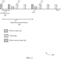
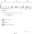
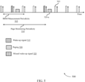
- Such techniques may be referred to as paging monitor periodicity without WUS (or page monitoring periodicity without WUS) and may enable the UE to monitor for paging information according to a periodicity configured by the network.
- the base station or network may configure the UE to monitor paging information according to a periodicity related to the PO periodicity, the WUS periodicity, an RRM measurement periodicity, or a modification period related to system information modification.
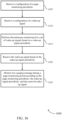
- a method of wireless communication at a UE may include receiving a configuration of a wake-up signal periodicity, performing discontinuous monitoring for a set of wake-up signals based on the wake-up signal periodicity, and performing a RRM measurement according to an RRM measurement periodicity, where the RRM measurement periodicity corresponds to one or more wake-up signal occasions according to the wake-up signal periodicity.
- the apparatus may include a processor, memory in electronic communication with the processor, and instructions stored in the memory.
- the instructions may be executable by the processor to cause the apparatus to receive a configuration of a wake-up signal periodicity, perform discontinuous monitoring for a set of wake-up signals based on the wake-up signal periodicity, and perform a RRM measurement according to an RRM measurement periodicity, where the RRM measurement periodicity corresponds to one or more wake-up signal occasions according to the wake-up signal periodicity.
- the apparatus may include means for receiving a configuration of a wake-up signal periodicity, performing discontinuous monitoring for a set of wake-up signals based on the wake-up signal periodicity, and performing a RRM measurement according to an RRM measurement periodicity, where the RRM measurement periodicity corresponds to one or more wake-up signal occasions according to the wake-up signal periodicity.
- a non-transitory computer-readable medium storing code for wireless communication is described.
- the code may include instructions executable by a processor to receive a configuration of a wake-up signal periodicity, perform discontinuous monitoring for a set of wake-up signals based on the wake-up signal periodicity, and perform a RRM measurement according to an RRM measurement periodicity, where the RRM measurement periodicity corresponds to one or more wake-up signal occasions according to the wake-up signal periodicity.
- Some examples of the method, apparatuses, and non-transitory computer-readable medium described herein may further include operations, features, means, or instructions for determining, based on the RRM measurement, a reference signal received power (RSRP), or a reference signal received quality (RSRQ), or a confirmation of a serving cell, or a combination thereof.
- the wake-up signal periodicity corresponds to one or more DRX cycles.
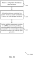
- Some examples of the method, apparatuses, and non-transitory computer-readable medium described herein may further include operations, features, means, or instructions for determining whether a wake-up signal may be detected at the one or more wake-up signal occasions, and performing the RRM measurement based on a determination that at least one wake-up signal may be detected at the one or more wake-up signal occasions.
- Some examples of the method, apparatuses, and non-transitory computer-readable medium described herein may further include operations, features, means, or instructions for determining whether a wake-up signal may be detected at the one or more wake-up signal occasions, and performing the RRM measurement at a temporally last wake-up signal occasion based on a determination that no wake-up signals were detected at the one or more wake-up signal occasions.
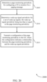
- a method of wireless communication may include determining a wake-up signal periodicity for a set of wake-up signals, configuring, based on the wake-up signal periodicity, a RRM measurement periodicity for a UE to perform an RRM measurement, where the RRM measurement periodicity corresponds to one or more wake-up signal occasions according to the wake-up signal periodicity, and transmitting a configuration indicating the RRM measurement periodicity to the UE.
- the apparatus may include a processor, memory in electronic communication with the processor, and instructions stored in the memory.
- the instructions may be executable by the processor to cause the apparatus to determine a wake-up signal periodicity for a set of wake-up signals, configure, based on the wake-up signal periodicity, a RRM measurement periodicity for a UE to perform an RRM measurement, where the RRM measurement periodicity corresponds to one or more wake-up signal occasions according to the wake-up signal periodicity, and transmit a configuration indicating the RRM measurement periodicity to the UE.
- a non-transitory computer-readable medium storing code for wireless communication is described.
- the code may include instructions executable by a processor to determine a wake-up signal periodicity for a set of wake-up signals, configure, based on the wake-up signal periodicity, a RRM measurement periodicity for a UE to perform an RRM measurement, where the RRM measurement periodicity corresponds to one or more wake-up signal occasions according to the wake-up signal periodicity, and transmit a configuration indicating the RRM measurement periodicity to the UE.
- Some examples of the method, apparatuses, and non-transitory computer-readable medium described herein may further include operations, features, means, or instructions for configuring the RRM measurement periodicity based on one or more RRM measurements performed by the UE.
- a base station may signal that paging and/or system information is available in a channel for one or more user equipment (UEs). For example, the base station may send pages or paging messages to a UE indicate that information is available for the UE.
- the paging messages may carry an indication of a change in system information (e.g., a modification of a system information block (SIB)).
- SIB system information block
- the paging messages may be sent during paging occasions (POs) of a downlink control channel.
- the downlink control channel may be a physical downlink control channel (PDCCH) or a narrowband (NB)-PDCCH.
- POs may be periodic intervals configured for paging messages to allow the UEs to enter a sleep or discontinuous reception (DRX) state in between POs, and this process may be referred to as idle mode paging.
- the paging information may be sent in a physical downlink shared channel (PDSCH), which may be sent during the same transmission time interval (TTI) (e.g., subframe) as the PDCCH or during a different TTI.
- TTI transmission time interval
- the network may change one or more information fields pertaining to system information. Further, the network may transmit a paging message indicating that the system information has been modified. For instance, the network may update a field or information element within the paging message pertaining to a modification in system information. Upon receiving a paging message indicating the change in system information, the UE may attempt to monitor for additional details pertaining to the change in system information.
- a UE capable of, and configured for, detecting a WUS may detect the WUS based on a WUS periodicity configured by higher layers.
- the network may configure a UE to monitor paging information periodically, even when a configured WUS is not detected. For instance, the network may configure the UE with a page monitoring periodicity to enable or trigger a UE to monitor paging information.
- the configuration may be explicitly signaled (e.g., via a SIB, a Radio Resource Control (RRC) configuration, a higher layer parameter, or the like), implicitly signaled, or may be determined based on preconfigured parameters.
- RRC Radio Resource Control
- aspects of the disclosure are initially described in the context of a wireless communications system. Aspects are the disclosure are then described with reference to timing diagrams. Aspects of the disclosure are further illustrated by and described with reference to apparatus diagrams, system diagrams, and flowcharts that relate to fallback mode for wake-up signal receivers.
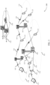
- FIG. 1 illustrates an example of a wireless communications system 100 in accordance with various aspects of the present disclosure.
- the wireless communications system 100 includes base stations 105, UEs 115, and a core network 130.
- the wireless communications system 100 may be a Long Term Evolution (LTE) network, an LTE-Advanced (LTE-A) network, or a New Radio (NR) network.
- LTE Long Term Evolution
- LTE-A LTE-Advanced
- NR New Radio
- wireless communications system 100 may support enhanced broadband communications, ultra-reliable (e.g., mission critical) communications, low latency communications, or communications with low-cost and low-complexity devices.
- ultra-reliable e.g., mission critical
- Base stations 105 may wirelessly communicate with UEs 115 via one or more base station antennas.
- Base stations 105 described herein may include or may be referred to by those skilled in the art as a base transceiver station, a radio base station, an access point, a radio transceiver, a NodeB, an eNodeB (eNB), a next-generation Node B or giga-nodeB (either of which may be referred to as a gNB), a Home NodeB, a Home eNodeB, or some other suitable terminology.
- Wireless communications system 100 may include base stations 105 of different types (e.g., macro or small cell base stations).
- the UEs 115 described herein may be able to communicate with various types of base stations 105 and network equipment including macro eNBs, small cell eNBs, gNBs, relay base stations, and the like.
- the geographic coverage area 110 for a base station 105 may be divided into sectors making up only a portion of the geographic coverage area 110, and each sector may be associated with a cell.
- each base station 105 may provide communication coverage for a macro cell, a small cell, a hot spot, or other types of cells, or various combinations thereof.
- a base station 105 may be movable and therefore provide communication coverage for a moving geographic coverage area 110.
- different geographic coverage areas 110 associated with different technologies may overlap, and overlapping geographic coverage areas 110 associated with different technologies may be supported by the same base station 105 or by different base stations 105.
- the wireless communications system 100 may include, for example, a heterogeneous LTE/LTE-A or NR network in which different types of base stations 105 provide coverage for various geographic coverage areas 110.
- Some UEs 115 may be low cost or low complexity devices, and may provide for automated communication between machines (e.g., via Machine-to-Machine (M2M) communication).
- M2M communication or MTC may refer to data communication technologies that allow devices to communicate with one another or a base station 105 without human intervention.
- M2M communication or MTC may include communications from devices that integrate sensors or meters to measure or capture information and relay that information to a central server or application program that can make use of the information or present the information to humans interacting with the program or application.
- Some UEs 115 may be designed to collect information or enable automated behavior of machines. Examples of applications for MTC devices include smart metering, inventory monitoring, water level monitoring, equipment monitoring, healthcare monitoring, wildlife monitoring, weather and geological event monitoring, fleet management and tracking, remote security sensing, physical access control, and transaction-based business charging.
- a UE 115 may also be able to communicate directly with other UEs 115 (e.g., using a peer-to-peer (P2P) or device-to-device (D2D) protocol).
- P2P peer-to-peer
- D2D device-to-device
- One or more of a group of UEs 115 utilizing D2D communications may be within the geographic coverage area 110 of a base station 105.
- Other UEs 115 in such a group may be outside the geographic coverage area 110 of a base station 105, or be otherwise unable to receive transmissions from a base station 105.
- groups of UEs 115 communicating via D2D communications may utilize a one-to-many (1:M) system in which each UE 115 transmits to every other UE 115 in the group.
- a base station 105 facilitates the scheduling of resources for D2D communications.
- D2D communications are carried out between UEs 115 without the involvement of a base station
- Base stations 105 may communicate with the core network 130 and with one another. For example, base stations 105 may interface with the core network 130 through backhaul links 132 (e.g., via an S1 or other interface). Base stations 105 may communicate with one another over backhaul links 134 (e.g., via an X2 or other interface) either directly (e.g., directly between base stations 105) or indirectly (e.g., via core network 130).
- backhaul links 132 e.g., via an S1 or other interface
- backhaul links 134 e.g., via an X2 or other interface
- the core network 130 may provide user authentication, access authorization, tracking, Internet Protocol (IP) connectivity, and other access, routing, or mobility functions.
- the core network 130 may be an evolved packet core (EPC), which may include at least one mobility management entity (MME), at least one serving gateway (S-GW), and at least one Packet Data Network (PDN) gateway (P-GW).
- the MME may manage non-access stratum (e.g., control plane) functions such as mobility, authentication, and bearer management for UEs 115 served by base stations 105 associated with the EPC.
- User IP packets may be transferred through the S-GW, which itself may be connected to the P-GW.
- the P-GW may provide IP address allocation as well as other functions.
- the P-GW may be connected to the network operators IP services.
- the operators IP services may include access to the Internet, Intranet(s), an IP Multimedia Subsystem (IMS), or a Packet-Switched (PS) Streaming Service.
- IMS IP Multimedia Subsystem
- At least some of the network devices may include subcomponents such as an access network entity, which may be an example of an access node controller (ANC).
- an access network entity may communicate with UEs 115 through a number of other access network transmission entities, which may be referred to as a radio head, a smart radio head, or a transmission/reception point (TRP).
- TRP transmission/reception point
- various functions of each access network entity or base station 105 may be distributed across various network devices (e.g., radio heads and access network controllers) or consolidated into a single network device (e.g., a base station 105).
- Wireless communications system 100 may operate using one or more frequency bands, typically in the range of 300 megahertz (MHz) to 300 gigahertz (GHz).
- MHz megahertz
- GHz gigahertz
- UHF ultra-high frequency
- the region from 300 MHz to 3 GHz is known as the ultra-high frequency (UHF) region or decimeter band, since the wavelengths range from approximately one decimeter to one meter in length.
- UHF waves may be blocked or redirected by buildings and environmental features. However, the waves may penetrate structures sufficiently for a macro cell to provide service to UEs 115 located indoors. Transmission of UHF waves may be associated with smaller antennas and shorter range (e.g., less than 100 km) compared to transmission using the smaller frequencies and longer waves of the high frequency (HF) or very high frequency (VHF) portion of the spectrum below 300 MHz.
- HF high frequency
- VHF very high frequency
- Operations in unlicensed spectrum may include downlink transmissions, uplink transmissions, peer-to-peer transmissions, or a combination of these.
- Duplexing in unlicensed spectrum may be based on frequency division duplexing (FDD), time division duplexing (TDD), or a combination of both.
- FDD frequency division duplexing
- TDD time division duplexing
- Beamforming which may also be referred to as spatial filtering, directional transmission, or directional reception, is a signal processing technique that may be used at a transmitting device or a receiving device (e.g., a base station 105 or a UE 115) to shape or steer an antenna beam (e.g., a transmit beam or receive beam) along a spatial path between the transmitting device and the receiving device.
- Beamforming may be achieved by combining the signals communicated via antenna elements of an antenna array such that signals propagating at particular orientations with respect to an antenna array experience constructive interference while others experience destructive interference.
- the adjustment of signals communicated via the antenna elements may include a transmitting device or a receiving device applying certain amplitude and phase offsets to signals carried via each of the antenna elements associated with the device.
- the adjustments associated with each of the antenna elements may be defined by a beamforming weight set associated with a particular orientation (e.g., with respect to the antenna array of the transmitting device or receiving device, or with respect to some other orientation).
- a base station 105 may use multiple antennas or antenna arrays to conduct beamforming operations for directional communications with a UE 115. For instance, some signals (e.g., synchronization signals, reference signals, beam selection signals, or other control signals) may be transmitted by a base station 105 multiple times in different directions, which may include a signal being transmitted according to different beamforming weight sets associated with different directions of transmission. Transmissions in different beam directions may be used to identify (e.g., by the base station 105 or a receiving device, such as a UE 115) a beam direction for subsequent transmission and/or reception by the base station 105.
- some signals e.g., synchronization signals, reference signals, beam selection signals, or other control signals
- Transmissions in different beam directions may be used to identify (e.g., by the base station 105 or a receiving device, such as a UE 115) a beam direction for subsequent transmission and/or reception by the base station 105.
- Some signals may be transmitted by a base station 105 in a single beam direction (e.g., a direction associated with the receiving device, such as a UE 115).
- the beam direction associated with transmissions along a single beam direction may be determined based at least in in part on a signal that was transmitted in different beam directions.
- a UE 115 may receive one or more of the signals transmitted by the base station 105 in different directions, and the UE 115 may report to the base station 105 an indication of the signal it received with a highest signal quality, or an otherwise acceptable signal quality.
- a receiving device may try multiple receive beams when receiving various signals from the base station 105, such as synchronization signals, reference signals, beam selection signals, or other control signals.
- a receiving device may try multiple receive directions by receiving via different antenna subarrays, by processing received signals according to different antenna subarrays, by receiving according to different receive beamforming weight sets applied to signals received at a plurality of antenna elements of an antenna array, or by processing received signals according to different receive beamforming weight sets applied to signals received at a plurality of antenna elements of an antenna array, any of which may be referred to as "listening" according to different receive beams or receive directions.
- a receiving device may use a single receive beam to receive along a single beam direction (e.g., when receiving a data signal).
- the single receive beam may be aligned in a beam direction determined based at least in part on listening according to different receive beam directions (e.g., a beam direction determined to have a highest signal strength, highest signal-to-noise ratio, or otherwise acceptable signal quality based at least in part on listening according to multiple beam directions).
- the antennas of a base station 105 or UE 115 may be located within one or more antenna arrays, which may support MIMO operations, or transmit or receive beamforming.
- one or more base station antennas or antenna arrays may be colocated at an antenna assembly, such as an antenna tower.
- antennas or antenna arrays associated with a base station 105 may be located in diverse geographic locations.
- a base station 105 may have an antenna array with a number of rows and columns of antenna ports that the base station 105 may use to support beamforming of communications with a UE 115.
- a UE 115 may have one or more antenna arrays that may support various MIMO or beamforming operations.
- wireless communications system 100 may be a packet-based network that operate according to a layered protocol stack.
- PDCP Packet Data Convergence Protocol
- a Radio Link Control (RLC) layer may in some cases perform packet segmentation and reassembly to communicate over logical channels.
- RLC Radio Link Control
- a Medium Access Control (MAC) layer may perform priority handling and multiplexing of logical channels into transport channels.
- the MAC layer may also use hybrid automatic repeat request (HARQ) to provide retransmission at the MAC layer to improve link efficiency.
- HARQ hybrid automatic repeat request
- the Radio Resource Control (RRC) protocol layer may provide establishment, configuration, and maintenance of an RRC connection between a UE 115 and a base station 105 or core network 130 supporting radio bearers for user plane data.
- RRC Radio Resource Control
- PHY Physical
- UEs 115 and base stations 105 may support retransmissions of data to increase the likelihood that data is received successfully.
- HARQ feedback is one technique of increasing the likelihood that data is received correctly over a communication link 125.
- HARQ may include a combination of error detection (e.g., using a cyclic redundancy check (CRC)), forward error correction (FEC), and retransmission (e.g., automatic repeat request (ARQ)).
- FEC forward error correction
- ARQ automatic repeat request
- HARQ may improve throughput at the MAC layer in poor radio conditions (e.g., signal-to-noise conditions).
- a wireless device may support same-slot HARQ feedback, where the device may provide HARQ feedback in a specific slot for data received in a previous symbol in the slot. In other cases, the device may provide HARQ feedback in a subsequent slot, or according to some other time interval.
- the radio frames may be identified by a system frame number (SFN) ranging from 0 to 1023.
- SFN system frame number
- Each frame may include 10 subframes numbered from 0 to 9, and each subframe may have a duration of 1 ms.
- a subframe may be further divided into 2 slots each having a duration of 0.5 ms, and each slot may contain 6 or 7 modulation symbol periods (e.g., depending on the length of the cyclic prefix prepended to each symbol period). Excluding the cyclic prefix, each symbol period may contain 2048 sampling periods.
- a subframe may be the smallest scheduling unit of the wireless communications system 100, and may be referred to as a transmission time interval (TTI).
- TTI transmission time interval
- a smallest scheduling unit of the wireless communications system 100 may be shorter than a subframe or may be dynamically selected (e.g., in bursts of shortened TTIs (sTTIs) or in selected component carriers using sTTIs).
- a slot may further be divided into multiple mini-slots containing one or more symbols.
- a symbol of a mini-slot or a mini-slot may be the smallest unit of scheduling.
- Each symbol may vary in duration depending on the subcarrier spacing or frequency band of operation, for example.
- some wireless communications systems may implement slot aggregation in which multiple slots or mini-slots are aggregated together and used for communication between a UE 115 and a base station 105.
- carrier refers to a set of radio frequency spectrum resources having a defined physical layer structure for supporting communications over a communication link 125.
- a carrier of a communication link 125 may include a portion of a radio frequency spectrum band that is operated according to physical layer channels for a given radio access technology.
- Each physical layer channel may carry user data, control information, or other signaling.
- a carrier may be associated with a pre-defined frequency channel (e.g., an E-UTRA absolute radio frequency channel number (EARFCN)), and may be positioned according to a channel raster for discovery by UEs 115.
- E-UTRA absolute radio frequency channel number E-UTRA absolute radio frequency channel number
- Carriers may be downlink or uplink (e.g., in an FDD mode), or be configured to carry downlink and uplink communications (e.g., in a TDD mode).
- signal waveforms transmitted over a carrier may be made up of multiple sub-carriers (e.g., using multi-carrier modulation (MCM) techniques such as OFDM or DFT-s-OFDM).
- MCM multi-carrier modulation
- the organizational structure of the carriers may be different for different radio access technologies (e.g., LTE, LTE-A, NR, etc.). For example, communications over a carrier may be organized according to TTIs or slots, each of which may include user data as well as control information or signaling to support decoding the user data.
- a carrier may also include dedicated acquisition signaling (e.g., synchronization signals or system information, etc.) and control signaling that coordinates operation for the carrier.
- acquisition signaling e.g., synchronization signals or system information, etc.
- control signaling that coordinates operation for the carrier.
- a carrier may also have acquisition signaling or control signaling that coordinates operations for other carriers.
- Physical channels may be multiplexed on a carrier according to various techniques.
- a physical control channel and a physical data channel may be multiplexed on a downlink carrier, for example, using time division multiplexing (TDM) techniques, frequency division multiplexing (FDM) techniques, or hybrid TDM-FDM techniques.
- control information transmitted in a physical control channel may be distributed between different control regions in a cascaded manner (e.g., between a common control region or common search space and one or more UE-specific control regions or UE-specific search spaces).
- a carrier may be associated with a particular bandwidth of the radio frequency spectrum, and in some examples the carrier bandwidth may be referred to as a "system bandwidth" of the carrier or the wireless communications system 100.
- the carrier bandwidth may be one of a number of predetermined bandwidths for carriers of a particular radio access technology (e.g., 1.4, 3, 5, 10, 15, 20, 40, or 80 MHz).
- each served UE 115 may be configured for operating over portions or all of the carrier bandwidth.
- some UEs 115 may be configured for operation using a narrowband protocol type that is associated with a predefined portion or range (e.g., set of subcarriers or RBs) within a carrier (e.g., "in-band" deployment of a narrowband protocol type).
- Devices of the wireless communications system 100 may have a hardware configuration that supports communications over a particular carrier bandwidth, or may be configurable to support communications over one of a set of carrier bandwidths.
- the wireless communications system 100 may include base stations 105 and/or UEs that can support simultaneous communications via carriers associated with more than one different carrier bandwidth.
- Wireless communications system 100 may support communication with a UE 115 on multiple cells or carriers, a feature which may be referred to as carrier aggregation (CA) or multi-carrier operation.
- a UE 115 may be configured with multiple downlink CCs and one or more uplink CCs according to a carrier aggregation configuration.
- Carrier aggregation may be used with both FDD and TDD component carriers.
- wireless communications system 100 may utilize enhanced component carriers (eCCs).
- eCC may be characterized by one or more features including wider carrier or frequency channel bandwidth, shorter symbol duration, shorter TTI duration, or modified control channel configuration.
- an eCC may be associated with a carrier aggregation configuration or a dual connectivity configuration (e.g., when multiple serving cells have a suboptimal or non-ideal backhaul link).
- An eCC may also be configured for use in unlicensed spectrum or shared spectrum (e.g., where more than one operator is allowed to use the spectrum).
- An eCC characterized by wide carrier bandwidth may include one or more segments that may be utilized by UEs 115 that are not capable of monitoring the whole carrier bandwidth or are otherwise configured to use a limited carrier bandwidth (e.g., to conserve power).
- an eCC may utilize a different symbol duration than other CCs, which may include use of a reduced symbol duration as compared with symbol durations of the other CCs.
- a shorter symbol duration may be associated with increased spacing between adjacent subcarriers.
- a device such as a UE 115 or base station 105, utilizing eCCs may transmit wideband signals (e.g., according to frequency channel or carrier bandwidths of 20, 40, 60, 80 MHz, etc.) at reduced symbol durations (e.g., 16.67 microseconds).
- a TTI in eCC may include of one or multiple symbol periods. In some cases, the TTI duration (that is, the number of symbol periods in a TTI) may be variable.
- Wireless communications systems such as an NR system, may utilize any combination of licensed, shared, and unlicensed spectrum bands, among others.
- the flexibility of eCC symbol duration and subcarrier spacing may allow for the use of eCC across multiple spectrums.
- NR shared spectrum may increase spectrum utilization and spectral efficiency, specifically through dynamic vertical (e.g., across frequency) and horizontal (e.g., across time) sharing of resources.
- a UE 115 may monitor a communication link 125 continuously for an indication that the UE 115 may receive data.
- a UE 115 may be configured with a discontinuous reception (DRX) cycle.
- a DRX cycle may include an "On Duration" when the UE 115 may monitor for control information (e.g., on PDCCH) and a "DRX period" when the UE 115 may power down radio components.
- a UE 115 may be configured with a short DRX cycle and a long DRX cycle.
- a UE 115 may enter a long DRX cycle if it is inactive for one or more short DRX cycles.
- the transition between the short DRX cycle, the long DRX cycle and continuous reception may be controlled by an internal timer or by messaging from a base station 105.
- a UE 115 may receive scheduling messages on PDCCH during the On Duration. While monitoring PDCCH for a scheduling message, the UE 115 may initiate a "DRX Inactivity Timer.” If a scheduling message is successfully received, the UE 115 may prepare to receive data and the DRX Inactivity Timer may be reset. When the DRX Inactivity Timer expires without receiving a scheduling message, the UE 115 may move into a short DRX cycle and may start a "DRX Short Cycle Timer.” When the DRX Short Cycle Timer expires, the UE 115 may resume a long DRX cycle.
- eDRX extended DRX
- PO periodicity may include a number of POs to monitor at a start of every eDRX periodicity and determined by a paging time window (PTW).
- PGW paging time window
- a base station 105 may signal a change in system information to a UE 115 via a page or paging message.
- the paging message may carry an indication of the change in system information and may also indicate that paging information is available for one or more UEs 115 associated with the base station 105.
- a UE 115 may periodically monitor for paging messages transmitted from the base station during POs.
- a PO may be a TTI where a downlink channel such as a PDCCH or PDSCH addresses the paging message.
- a base station 105 in wireless communications system 100 may use a WUS during idle-mode paging to indicate if the UE 115 needs to decode a particular physical downlink channel to determine whether there is a change in system information.
- the UE 115 may refrain from monitoring POs until a WUS has been detected prior to a PO.
- the network may configure a UE 115 to monitor POs regardless of an absence of a WUS.
- a paging monitor periodicity without WUS may be configured and may enable the UE 115 to periodically monitor for paging information according to a cycle configured by the network.
- the base station 105 or network may configure the UE 115 to monitor paging information according to a cycle related to the PO periodicity, the WUS periodicity, RRM measurement periodicity, or a modification period related to system information modification.
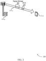
- FIG. 2 illustrates an example of a wireless communication system 200 that supports an RRM configuration for UEs with WUS receivers in accordance with various aspects of the present disclosure.
- wireless communications system 200 may implement aspects of wireless communications system 100.
- Wireless communications system 200 may include base station 105-a and UE 115-a, which may be examples of the corresponding devices described with reference to FIG. 1 .
- Base station 105-a and UE 115-a may be in communication with each other over communication link 125-a.
- wireless communications system 200 may operate in mmW spectrum, or may support radio technologies such as NB-IoT, or eMTC.
- base station 105-a may send pages or paging messages 205 to one or more UEs 115, including UE 115-a, to indicate that information (such as downlink data or other information) is available for one or more of the UEs 115.
- the paging messages 205 may also carry an indication of a change in system information (e.g., in a SIB).
- the paging messages 205 may be sent using POs of a downlink control channel, where the downlink control channel may be a PDCCH or a NB-PDCCH.
- POs may be periodic intervals configured for paging messages 205 to allow UE 115-a to enter a sleep or DRX state in between POs, and this process may be referred to as idle mode paging.
- the paging information may be sent in a PDSCH, which may be sent during the same TTI as a PDCCH or during a different TTI than the PDCCH.
- base station 105-a may use a power saving physical signal (e.g., WUS 210) to indicate if UE 115-a should decode a subsequent downlink physical channel (e.g., PDCCH or PDSCH) in idle mode paging.
- WUS 210 may serve to optimize power consumption at UE 115-a, for example, where UE 115-a may rely on receipt of WUS 210 before waking from a sleep state.
- base station 105-a may introduce a periodic synchronization signals (e.g., PSS or SSS) in combination with WUS 210 (and/or with DTX) to ensure sufficient synchronization performance. In other cases, base station 105-a may not introduce periodic synchronization signals in a WUS mode (which may also correspond to a DTX mode).
- the network or base station 105-a may change one or more information fields pertaining to a SIB.
- base station 105-a may proceed to transmit the modified SIB, as well as another SIB (e.g., SIB1) with an updated field (e.g., systemInfoValueTag ).
- base station 105-a may transmit paging message 205 with an indication that the system information has been modified. For instance, the base station 105-a may update a field or information element within paging message 205 pertaining to a modification in system information (e.g., systemInfoModification ).
- the field may comprise a Boolean value and may, for example, be set to "true" (e.g., using Boolean logic with a bit value of '1').
- UE 115-a may attempt monitoring for SIB1 for additional details pertaining to the change in system information. For instance, the systemInfoValueTag transmitted within SIB1 may change during a modification period, and may provide an indication of the change in system information.
- the modification period may be specified in another system information block (e.g., modificationPeriodCoeff in SIB2).
- UE 115-a may determine that the system information changes at the boundary of a next modification period.
- UE 115-a may be capable of and configured to detect WUS 210, and may thus detect WUS 210 based on a WUS periodicity configured by higher layers. Thus, if UE 115-a is configured to detect WUS 210 for power saving, UE 115-a may not read a downlink channel, such as PDCCH or PDSCH, if WUS 210 is not detected. In some circumstances, however, UE 115-a may miss WUS 210 even though WUS 210 was transmitted for paging message 205. For instance, a large MCL due to a relatively large coverage area, frequency offset, time drift, or inter-cell interference with a neighboring base station 105 (not shown) or another device may lead to a missed WUS 210.
- a downlink channel such as PDCCH or PDSCH
- base station 105-b may determine a page monitoring periodicity (e.g., "page monitoring periodicity without WUS ”) for configuring UE 115-b to monitor for a paging message.
- WUSs may be deployed as power saving signals, enabling a UE to remain in idle mode until a paging message of a PO indicates a change in system information, or paging information for the UE.
- base station 105-b may thus determine a WUS periodicity for a plurality of WUSs, where the WUS periodicity may be less than or equal to the page monitoring periodicity.
- UE communications manager 815 or receiver 810 may receive a configuration of a page monitoring periodicity, and receive a configuration of a WUS. In some cases, UE communications manager 815 may perform discontinuous monitoring for a set of WUSs based on a WUS periodicity, and monitor for a paging message during a page monitoring period according to the page monitoring periodicity, the WUS periodicity, and the received WUS.
- UE communications manager 815 may receive a configuration of a wake-up signal periodicity, perform discontinuous monitoring for a plurality of wake-up signals based at least in part on the wake-up signal periodicity, and perform an RRM measurement according to an RRM measurement periodicity, wherein the RRM measurement periodicity corresponds to one or more wake-up signal occasions according to the wake-up signal periodicity.
- Transmitter 820 may transmit signals generated by other components of the device. In some cases, transmitter 820 may receive information from other components of the device via link 830. In some examples, the transmitter 820 may be collocated with a receiver 810 in a transceiver module. For example, the transmitter 820 may be an example of aspects of the transceiver 1135 described with reference to FIG. 11 . The transmitter 820 may utilize a single antenna or a set of antennas.
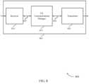
- FIG. 9 shows a block diagram 900 of a wireless device 905 that supports an RRM configuration for UEs with WUS receivers in accordance with aspects of the present disclosure.
- Wireless device 905 may be an example of aspects of a wireless device 805 or a UE 115 as described with reference to FIG. 8 .
- Wireless device 905 may include receiver 910, UE communications manager 915, and transmitter 920.
- Wireless device 905 may also include a processor. Each of these components may be in communication with one another (e.g., via one or more buses).
- UE page monitoring component 925 may receive a configuration of a page monitoring periodicity, identify a system information change notification based on a detected paging message, and determine that the page monitoring periodicity includes one or more POs based on the configuration.
- the WUS periodicity may correspond to the one or more Pos.
- UE page monitoring component 925 may monitor for the paging message according to a PO periodicity and the received WUS.
- UE page monitoring component 925 may monitor for the paging message according to the PTW periodicity and the received WUS and/or monitor for the paging message according to an RRM measurement periodicity.
- UE page monitoring component 925 may identify the configuration of the page monitoring periodicity based on a relationship between the page monitoring periodicity and one or more other parameters, and detect the paging message during the page monitoring period based on the monitoring, where the paging message is detected based on the received WUS. In some cases, UE page monitoring component 925 may monitor, according to a BCCH modification period, for the paging message, a system information block, a MIB, or a combination thereof. In some cases, receiving the configuration of the page monitoring periodicity includes: receiving the configuration of the page monitoring periodicity via a system information message, an RRC message, a NAS message, or a combination thereof. In some cases, UE page monitoring component 925 may be in communication with various components of UE communications manager 915 via link 950.
- Transmitter 920 may transmit signals generated by other components of the device, and received via link 945.
- the transmitter 920 may be collocated with a receiver 910 in a transceiver module.
- the transmitter 920 may be an example of aspects of the transceiver 1135 described with reference to FIG. 11 .
- the transmitter 920 may utilize a single antenna or a set of antennas.
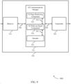
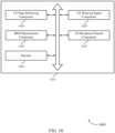
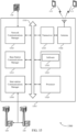
- FIG. 10 shows a block diagram 1000 of a UE communications manager 1015 that supports an RRM configuration for UEs with WUS receivers in accordance with aspects of the present disclosure.
- the UE communications manager 1015 may be an example of aspects of a UE communications manager 815, a UE communications manager 915, or a UE communications manager 1115 described with reference to FIGs. 8 , 9 , and 11 .
- the UE communications manager 1015 may include UE page monitoring component 1020, UE wake-up signal component 1025, RRM measurement component 1030, UE broadcast channel component 1035, and decoder 1040. Each of these modules may communicate, directly or indirectly, with one another (e.g., via one or more buses).
- UE broadcast channel component 1035 may determine that the page monitoring periodicity includes one or more BCCH modification periods based on the configuration.
- Decoder 1040 may decode information such as packets, user data, or control information associated with various information channels (e.g., control channels, data channels, and information related to fallback mode for WUS receivers, etc.) obtained by the various components of UE communications manager 1015, or wireless device hosting the UE communications manager.
- Processor 1120 may include an intelligent hardware device, (e.g., a general-purpose processor, a DSP, a central processing unit (CPU), a microcontroller, an ASIC, an FPGA, a programmable logic device, a discrete gate or transistor logic component, a discrete hardware component, or any combination thereof).
- processor 1120 may be configured to operate a memory array using a memory controller.
- a memory controller may be integrated into processor 1120.
- Processor 1120 may be configured to execute computer-readable instructions stored in a memory to perform various functions (e.g., functions or tasks supporting fallback mode for WUS receivers).
- Memory 1125 may include random-access memory (RAM) and read-only memory (ROM).
- RAM random-access memory
- ROM read-only memory
- the memory 1125 may store computer-readable, computer-executable software 1130 including instructions that, when executed, cause the processor to perform various functions described herein.
- the memory 1125 may contain, among other things, a basic input/output system (BIOS) which may control basic hardware or software operation such as the interaction with peripheral components or devices.
- BIOS basic input/output system
- Software 1130 may include code to implement aspects of the present disclosure, including code to support fallback mode for WUS receivers.
- Software 1130 may be stored in a non-transitory computer-readable medium such as system memory or other memory. In some cases, the software 1130 may not be directly executable by the processor but may cause a computer (e.g., when compiled and executed) to perform functions described herein.
- Transceiver 1135 may communicate bi-directionally, via one or more antennas, wired, or wireless links as described herein.
- the transceiver 1135 may represent a wireless transceiver and may communicate bi-directionally with another wireless transceiver.
- the transceiver 1135 may also include a modem to modulate the packets and provide the modulated packets to the antennas for transmission, and to demodulate packets received from the antennas.
- the wireless device may include a single antenna 1140. However, in some cases the device may have more than one antenna 1140, which may be capable of concurrently transmitting or receiving multiple wireless transmissions.
- I/O controller 1145 may manage input and output signals for device 1105. I/O controller 1145 may also manage peripherals not integrated into device 1105. In some cases, I/O controller 1145 may represent a physical connection or port to an external peripheral. In some cases, I/O controller 1145 may utilize an operating system such as iOS ® , ANDROID ® , MS-DOS ® , MS-WINDOWS ® , OS/2 ® , UNIX ® , LINUX ® , or another known operating system. In other cases, I/O controller 1145 may represent or interact with a modem, a keyboard, a mouse, a touchscreen, or a similar device. In some cases, I/O controller 1145 may be implemented as part of a processor. In some cases, a user may interact with device 1105 via I/O controller 1145 or via hardware components controlled by I/O controller 1145.
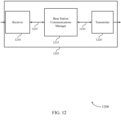
- FIG. 12 shows a block diagram 1200 of a wireless device 1205 that supports an RRM configuration for UEs with WUS receivers in accordance with aspects of the present disclosure.
- Wireless device 1205 may be an example of aspects of a base station 105 as described herein.
- Wireless device 1205 may include receiver 1210, base station communications manager 1215, and transmitter 1220.
- Wireless device 1205 may also include a processor. Each of these components may be in communication with one another (e.g., via one or more buses).
- Receiver 1210 may receive information such as packets, user data, or control information associated with various information channels (e.g., control channels, data channels, and information related to fallback mode for WUS receivers, etc.). Information may be passed on to other components of the device via link 1225.
- the receiver 1210 may be an example of aspects of the transceiver 1535 described with reference to FIG. 15 .
- the receiver 1210 may utilize a single antenna or a set of antennas.
- Base station communications manager 1215 may be an example of aspects of the base station communications manager 1515 described with reference to FIG. 15 .
- Base station communications manager 1215 and/or at least some of its various sub-components may be implemented in hardware, software executed by a processor, firmware, or any combination thereof. If implemented in software executed by a processor, the functions of the base station communications manager 1215 and/or at least some of its various sub-components may be executed by a general-purpose processor, a DSP, an ASIC, an FPGA or other programmable logic device, discrete gate or transistor logic, discrete hardware components, or any combination thereof designed to perform the functions described in the present disclosure.
- the base station communications manager 1215 and/or at least some of its various sub-components may be physically located at various positions, including being distributed such that portions of functions are implemented at different physical locations by one or more physical devices.
- base station communications manager 1215 and/or at least some of its various sub-components may be a separate and distinct component in accordance with various aspects of the present disclosure.
- base station communications manager 1215 may pass on information to transmitter 1220 via link 1230, and may receiver information from receiver 1210 via link 1225.
- base station communications manager 1215 and/or at least some of its various sub-components may be combined with one or more other hardware components, including but not limited to an I/O component, a transceiver, a network server, another computing device, one or more other components described in the present disclosure, or a combination thereof in accordance with various aspects of the present disclosure.
- Base station communications manager 1215 may determine a page monitoring periodicity for configuring a UE 115 to monitor for a paging message and determine a WUS periodicity for a set of WUSs, the WUS periodicity being less than or equal to the page monitoring periodicity.
- base station communications manager 1215 may determine a wake-up signal periodicity for a plurality of wake-up signals, configure, based on the wake-up signal periodicity, an RRM measurement periodicity for a UE to perform an RRM measurement, wherein the RRM measurement periodicity corresponds to one or more wake-up signal occasions according to the wake-up signal periodicity, and transmit a configuration indicating the RRM measurement periodicity to the UE.
- Transmitter 1220 may transmit signals generated by other components of the device, and received via link 1230.
- the transmitter 1220 may be collocated with a receiver 1210 in a transceiver module.
- the transmitter 1220 may be an example of aspects of the transceiver 1535 described with reference to FIG. 15 .
- the transmitter 1220 may utilize a single antenna or a set of antennas.
- Transmitter 1220 may transmit a configuration of the page monitoring periodicity to the UE, where the configuration indicates a relationship between the page monitoring periodicity and the WUS periodicity.
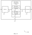
- FIG. 13 shows a block diagram 1300 of a wireless device 1305 that supports an RRM configuration for UEs with WUS receivers in accordance with aspects of the present disclosure.
- Wireless device 1305 may be an example of aspects of a wireless device 1205 or a base station 105 as described with reference to FIG. 12 .
- Wireless device 1305 may include receiver 1310, base station communications manager 1315, and transmitter 1320.
- Wireless device 1305 may also include a processor. Each of these components may be in communication with one another (e.g., via one or more buses).
- Receiver 1310 may receive information such as packets, user data, or control information associated with various information channels (e.g., control channels, data channels, and information related to fallback mode for WUS receivers, etc.). Information may be passed on to other components of the device via link 1335.
- the receiver 1310 may be an example of aspects of the transceiver 1535 described with reference to FIG. 15 .
- the receiver 1310 may utilize a single antenna or a set of antennas.
- Base station communications manager 1315 may be an example of aspects of the base station communications manager 1515 described with reference to FIG. 15 .
- Base station communications manager 1315 may also include base station page monitoring component 1325 and base station wake-up signal component 1330.
- Base station page monitoring component 1325 may determine a page monitoring periodicity for configuring a UE 115 to monitor for a paging message and transmit, within the configuration, an indication that the page monitoring periodicity includes one or more POs, where the WUS periodicity corresponds to the one or more POs.
- transmitting the configuration of the page monitoring periodicity includes transmitting the configuration of the page monitoring periodicity via a system information message, or an RRC message, or a NAS message, or a combination thereof.
- Base station wake-up signal component 1330 may determine a WUS periodicity for a set of WUSs, the WUS periodicity being less than or equal to the page monitoring periodicity, transmit, within the configuration, an indication that the page monitoring periodicity includes one or more WUS occasions, where the WUS periodicity corresponds to a PTW periodicity that includes one or more POs, and transmit, within the configuration, an indication that the page monitoring periodicity includes one or more WUS occasions based on the configuration, where the WUS periodicity corresponds to one or more POs.
- Transmitter 1320 may transmit signals generated by other components of the device, and received via link 1340.
- the transmitter 1320 may be collocated with a receiver 1310 in a transceiver module.
- the transmitter 1320 may be an example of aspects of the transceiver 1535 described with reference to FIG. 15 .
- the transmitter 1320 may utilize a single antenna or a set of antennas.
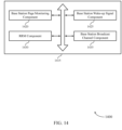
- FIG. 14 shows a block diagram 1400 of a base station communications manager 1415 that supports an RRM configuration for UEs with WUS receivers in accordance with aspects of the present disclosure.
- the base station communications manager 1415 may be an example of aspects of a base station communications manager 1515 described with reference to FIGs. 12 , 13 , and 15 .
- the base station communications manager 1415 may include base station page monitoring component 1420, base station wake-up signal component 1425, RRM component 1430, and base station broadcast channel component 1435. Each of these modules may communicate, directly or indirectly, with one another (e.g., via one or more buses).
- Base station page monitoring component 1420 may determine a page monitoring periodicity for configuring a UE 115 to monitor for a paging message and transmit, within the configuration, an indication that the page monitoring periodicity includes one or more POs, where the WUS periodicity corresponds to the one or more POs.
- transmitting the configuration of the page monitoring periodicity includes transmitting the configuration of the page monitoring periodicity via a system information message, or an RRC message, or a NAS message, or a combination thereof.
- Base station wake-up signal component 1425 may determine a WUS periodicity for a set of WUSs, the WUS periodicity being less than or equal to the page monitoring periodicity. In some cases, base station wake-up signal component 1425 may transmit, within the configuration, an indication that the page monitoring periodicity includes one or more WUS occasions, where the WUS periodicity corresponds to a PTW periodicity that includes one or more Pos. Additionally or alternatively, base station wake-up signal component 1425 may transmit, within the configuration, an indication that the page monitoring periodicity includes one or more WUS occasions based on the configuration, where the WUS periodicity corresponds to one or more POs.
- RRM component 1430 may transmit, within the configuration, an indication that the page monitoring periodicity includes one or more RRM measurement periods.
- Base station broadcast channel component 1435 may transmit, within the configuration, an indication that the page monitoring periodicity includes one or more BCCH modification periods and transmit a system information change notification within the paging message.
- FIG. 15 shows a diagram of a system 1500 including a device 1505 that supports an RRM configuration for UEs with WUS receivers in accordance with aspects of the present disclosure.
- Device 1505 may be an example of or include the components of base station 105 as described herein, e.g., with reference to FIG. 1 .
- Device 1505 may include components for bi-directional voice and data communications including components for transmitting and receiving communications, including base station communications manager 1515, processor 1520, memory 1525, software 1530, transceiver 1535, antenna 1540, network communications manager 1545, and inter-station communications manager 1550. These components may be in electronic communication via one or more buses (e.g., bus 1510).
- Device 1505 may communicate wirelessly with one or more UEs 115.
- Processor 1520 may include an intelligent hardware device, (e.g., a general-purpose processor, a DSP, a CPU, a microcontroller, an ASIC, an FPGA, a programmable logic device, a discrete gate or transistor logic component, a discrete hardware component, or any combination thereof).
- processor 1520 may be configured to operate a memory array using a memory controller.
- a memory controller may be integrated into processor 1520.
- Processor 1520 may be configured to execute computer-readable instructions stored in a memory to perform various functions (e.g., functions or tasks supporting fallback mode for WUS receivers).
- Memory 1525 may include RAM and ROM.
- the memory 1525 may store computer-readable, computer-executable software 1530 including instructions that, when executed, cause the processor to perform various functions described herein.
- the memory 1525 may contain, among other things, a BIOS which may control basic hardware or software operation such as the interaction with peripheral components or devices.
- Software 1530 may include code to implement aspects of the present disclosure, including code to support fallback mode for WUS receivers.
- Software 1530 may be stored in a non-transitory computer-readable medium such as system memory or other memory. In some cases, the software 1530 may not be directly executable by the processor but may cause a computer (e.g., when compiled and executed) to perform functions described herein.
- Inter-station communications manager 1550 may manage communications with other base station 105, and may include a controller or scheduler for controlling communications with UEs 115 in cooperation with other base stations 105. For example, the inter-station communications manager 1550 may coordinate scheduling for transmissions to UEs 115 for various interference mitigation techniques such as beamforming or joint transmission. In some examples, inter-station communications manager 1550 may provide an X2 interface within an LTE/LTE-A wireless communication network technology to provide communication between base stations 105.
- transmitting the configuration of the page monitoring periodicity to the UE 115 may include identifying time and frequency resources over which the configuration is transmitted, obtaining bits for the transmission from the base station page monitoring component, and encoding them prior to transmission.
- the encoding may be performed based on a modulation and coding scheme determined by the base station 105.
- a femto cell may also cover a small geographic area (e.g., a home) and may provide restricted access by UEs 115 having an association with the femto cell (e.g., UEs 115 in a closed subscriber group (CSG), UEs 115 for users in the home, and the like).
- An eNB for a macro cell may be referred to as a macro eNB.
- An eNB for a small cell may be referred to as a small cell eNB, a pico eNB, a femto eNB, or a home eNB.
- An eNB may support one or multiple (e.g., two, three, four, and the like) cells, and may also support communications using one or multiple component carriers.
Landscapes
- Engineering & Computer Science (AREA)
- Computer Networks & Wireless Communication (AREA)
- Signal Processing (AREA)
- Computer Security & Cryptography (AREA)
- Quality & Reliability (AREA)
- Physics & Mathematics (AREA)
- Electromagnetism (AREA)
- Mobile Radio Communication Systems (AREA)
Applications Claiming Priority (3)
| Application Number | Priority Date | Filing Date | Title |
|---|---|---|---|
| US201762585478P | 2017-11-13 | 2017-11-13 | |
| US16/182,380 US10820299B2 (en) | 2017-11-13 | 2018-11-06 | Radio resource management configuration for user equipment with wake-up signal receivers |
| PCT/US2018/059662 WO2019094494A1 (en) | 2017-11-13 | 2018-11-07 | Radio resource management configuration for user equipment with wake-up signal receivers |
Publications (3)
| Publication Number | Publication Date |
|---|---|
| EP3711370A1 EP3711370A1 (en) | 2020-09-23 |
| EP3711370C0 EP3711370C0 (en) | 2025-03-26 |
| EP3711370B1 true EP3711370B1 (en) | 2025-03-26 |
Family
ID=66431520
Family Applications (2)
| Application Number | Title | Priority Date | Filing Date |
|---|---|---|---|
| EP18807822.4A Active EP3711370B1 (en) | 2017-11-13 | 2018-11-07 | Radio resource management configuration for user equipment with wake-up signal receivers |
| EP18807526.1A Pending EP3711399A1 (en) | 2017-11-13 | 2018-11-07 | Fallback mode for wake-up signal receivers |
Family Applications After (1)
| Application Number | Title | Priority Date | Filing Date |
|---|---|---|---|
| EP18807526.1A Pending EP3711399A1 (en) | 2017-11-13 | 2018-11-07 | Fallback mode for wake-up signal receivers |
Country Status (9)
Families Citing this family (76)
| Publication number | Priority date | Publication date | Assignee | Title |
|---|---|---|---|---|
| US10772052B2 (en) * | 2017-06-16 | 2020-09-08 | Qualcomm Incorporated | Controlling coexistent radio systems in a wireless device |
| US10834699B2 (en) | 2017-11-13 | 2020-11-10 | Qualcomm Incorporated | Fallback mode for wake-up signal receivers |
| WO2019096912A1 (en) | 2017-11-15 | 2019-05-23 | Sony Corporation | To reduce power consumption for all types of terminal device |
| WO2019149109A1 (zh) | 2018-02-01 | 2019-08-08 | 华为技术有限公司 | 一种系统消息更新的方法、装置及系统 |
| CN110113805B (zh) * | 2018-02-01 | 2021-01-05 | 华为技术有限公司 | 一种系统消息更新的方法、装置及系统 |
| US11457436B2 (en) * | 2018-02-15 | 2022-09-27 | Sony Corporation | Unused portion of radio resources |
| US11751132B2 (en) * | 2018-02-15 | 2023-09-05 | Sony Corporation | Wake-up signal candidate indicator |
| US10652826B2 (en) | 2018-03-23 | 2020-05-12 | Samsung Electronics Co., Ltd. | Method and apparatus for power saving signal design in NR |
| KR102546164B1 (ko) | 2018-04-05 | 2023-06-22 | 삼성전자주식회사 | 무선 통신 시스템에서 빔 실패 복구를 위한 장치 및 방법 |
| EP3808130A1 (en) * | 2018-06-15 | 2021-04-21 | Sharp Kabushiki Kaisha | Apparatus and method for acquisition of system information in wireless communications |
| US11109344B2 (en) * | 2019-05-01 | 2021-08-31 | Lg Electronics Inc. | Start and stop of reception of downlink transmission based on paging |
| US11265845B2 (en) * | 2019-05-02 | 2022-03-01 | Mediatek Singapore Pte. Ltd. | Backup paging opportunities in new radio unlicensed |
| CN111885682A (zh) * | 2019-05-03 | 2020-11-03 | 华为技术有限公司 | 唤醒终端设备的方法、装置、网络设备和终端设备 |
| CA3139839A1 (en) * | 2019-05-10 | 2020-11-19 | Nokia Technologies Oy | Wake-up signal monitoring indication |
| US11595897B2 (en) * | 2019-05-15 | 2023-02-28 | Qualcomm Incorporated | Wireless communication addressing conflicts with a wake-up signal |
| CN112104987B (zh) * | 2019-06-18 | 2023-04-18 | 华为技术有限公司 | 一种消息传输的方法及相应设备 |
| WO2020258103A1 (zh) | 2019-06-26 | 2020-12-30 | 北京小米移动软件有限公司 | 监听方法、指示下发方法及装置、通信设备及存储 |
| WO2021002550A1 (en) * | 2019-07-01 | 2021-01-07 | Lg Electronics Inc. | Method and apparatus for monitoring downlink control channel based on wake up signalling in wireless communication system |
| WO2021012130A1 (zh) * | 2019-07-19 | 2021-01-28 | 北京小米移动软件有限公司 | 监听处理、策略下发方法及装置、通信设备及存储 |
| US12250633B2 (en) | 2019-07-26 | 2025-03-11 | Lg Electronics Inc. | Method for monitoring control channel, and device using method |
| CN112312522B (zh) * | 2019-08-01 | 2022-03-29 | 大唐移动通信设备有限公司 | 节能下行控制信道信息的传输方法、终端及网络侧设备 |
| CN112399498B (zh) | 2019-08-15 | 2021-09-07 | 华为技术有限公司 | 用于小区测量的方法和装置 |
| US11533685B2 (en) * | 2019-08-16 | 2022-12-20 | Qualcomm Incorporated | Wake-up behavior indication for power saving |
| WO2021035733A1 (zh) * | 2019-08-30 | 2021-03-04 | 华为技术有限公司 | 一种通信方法、装置及计算机可读存储介质 |
| CN113966636B (zh) * | 2019-09-30 | 2023-03-10 | 华为技术有限公司 | 通信方法、设备及系统 |
| US20220330154A1 (en) * | 2019-10-01 | 2022-10-13 | Nokia Technologies Oy | Adapting at least one operation parameter |
| WO2021066727A1 (en) * | 2019-10-03 | 2021-04-08 | Telefonaktiebolaget Lm Ericsson (Publ) | Rotation of group wake-up signal |
| US11617155B2 (en) * | 2019-10-08 | 2023-03-28 | Samsung Electronics Co., Ltd. | Method and apparatus for UE power saving in RRC_IDLE/INACTIVE STATE |
| EP4055898A4 (en) * | 2019-11-07 | 2023-07-19 | ZTE Corporation | METHODS, DEVICE AND SYSTEMS FOR DETERMINING A RESOURCE FOR WAKE-UP TRANSMISSIONS |
| US11546738B2 (en) * | 2019-11-14 | 2023-01-03 | Qualcomm Incorporated | Always-on short messages |
| CN114651500A (zh) * | 2019-11-20 | 2022-06-21 | 高通股份有限公司 | 管理控制信道监测 |
| EP4066546A1 (en) * | 2019-11-27 | 2022-10-05 | Telefonaktiebolaget LM Ericsson (publ) | Wake-up signal monitoring optimization |
| CN114424672B (zh) * | 2019-12-17 | 2024-07-26 | Oppo广东移动通信有限公司 | 监听唤醒信号的方法、终端设备和网络设备 |
| CN115066973B (zh) | 2020-02-07 | 2025-08-12 | 诺基亚技术有限公司 | 用于通信的装置、方法和计算机产品 |
| EP4104525A1 (en) * | 2020-02-13 | 2022-12-21 | Sony Group Corporation | Activation of wake-up signaling operation |
| WO2021162623A1 (en) * | 2020-02-13 | 2021-08-19 | Telefonaktiebolaget Lm Ericsson (Publ) | Aspects of wus transmission in idle mode |
| WO2021170908A1 (en) * | 2020-02-25 | 2021-09-02 | Nokia Technologies Oy | Adjusting a user equipment activity timing based on multiple signal sources for wireless network |
| US20240049139A1 (en) * | 2020-03-10 | 2024-02-08 | Telefonaktiebolaget Lm Ericsson (Publ) | Methods for Low Energy Movement Detection in Wireless Communication Devices |
| CN113498166B (zh) * | 2020-04-07 | 2023-01-24 | 维沃移动通信有限公司 | 资源指示方法和通信设备 |
| CN113518351B (zh) * | 2020-04-09 | 2024-11-26 | 维沃移动通信有限公司 | 一种模式判决方法及终端设备 |
| CN113556706B (zh) * | 2020-04-24 | 2023-09-05 | 维沃移动通信有限公司 | 无线资源管理测量方法、终端设备和网络设备 |
| US11683757B2 (en) * | 2020-06-22 | 2023-06-20 | Qualcomm Incorporated | Leveraging wake-up signals and discontinuous reception cycles for assisted antenna calibration |
| CN113938995B (zh) * | 2020-07-14 | 2023-09-22 | 华为技术有限公司 | 一种通信方法及设备 |
| WO2022016467A1 (en) * | 2020-07-23 | 2022-01-27 | Apple Inc. | Wake-up signal reception for paging operations |
| EP4165909A4 (en) | 2020-07-23 | 2023-07-19 | Apple Inc. | TRANSMISSION OF WAKE-UP SIGNALS FOR PHONE OPERATIONS |
| CN116210283A (zh) * | 2020-07-23 | 2023-06-02 | 苹果公司 | 确定用于寻呼接收的唤醒信号的位置 |
| CN114071496B (zh) * | 2020-07-31 | 2025-06-13 | 维沃移动通信有限公司 | 寻呼消息的监听方法及装置、终端和可读存储介质 |
| KR20220021049A (ko) * | 2020-08-12 | 2022-02-22 | 삼성전자주식회사 | 페이징 메시지를 수신하는 전자 장치 및 그 동작 방법 |
| US12041547B2 (en) * | 2020-08-14 | 2024-07-16 | Qualcomm Incorporated | Positioning reference signal (PRS) bundling across multiple discontinuous reception (multi-DRX) groups |
| US12041544B2 (en) | 2020-10-14 | 2024-07-16 | Apple Inc. | Wireless network having an enhanced wake-up signal |
| WO2022077255A1 (en) | 2020-10-14 | 2022-04-21 | Apple Inc. | Enhanced wake-up signal based power saving for a wireless device |
| WO2022088002A1 (en) * | 2020-10-30 | 2022-05-05 | Apple Inc. | Paging a user equipment in idle or inactive state |
| CN112600657B (zh) * | 2020-12-11 | 2022-06-28 | 紫光展锐(重庆)科技有限公司 | 一种定位的启动方法及相关装置 |
| EP4280800A4 (en) * | 2021-01-13 | 2024-10-23 | Beijing Xiaomi Mobile Software Co., Ltd. | INFORMATION PROCESSING METHOD AND APPARATUS, COMMUNICATION DEVICE AND STORAGE MEDIUM |
| EP4030835A1 (en) * | 2021-01-14 | 2022-07-20 | Panasonic Intellectual Property Corporation of America | User equipment and base station involved in paging |
| BR112023013939A2 (pt) * | 2021-01-15 | 2023-10-17 | Beijing Xiaomi Mobile Software Co Ltd | Método para configuração de informações, dispositivo de comunicação, e, meio de armazenamento legível por computador não transitório |
| WO2022205042A1 (en) | 2021-03-31 | 2022-10-06 | Zte Corporation | Method, device, and system for wake up burst in wireless networks |
| CN115623559A (zh) * | 2021-07-12 | 2023-01-17 | 展讯通信(上海)有限公司 | 一种寻呼方法、计算机可读存储介质和用户设备 |
| CN115623592B (zh) * | 2021-07-13 | 2025-08-29 | 华为技术有限公司 | 通信的方法和装置 |
| CN113728696B (zh) * | 2021-07-23 | 2025-03-04 | 北京小米移动软件有限公司 | 一种寻呼监测方法、寻呼监测装置及存储介质 |
| KR20240071411A (ko) * | 2021-09-30 | 2024-05-22 | 인터디지탈 패튼 홀딩스, 인크 | 무선 시스템용 저전력 웨이크업 수신기를 사용한 rrm 측정 및 페이징 신뢰성을 위한 방법들 및 장치 |
| WO2023130460A1 (en) * | 2022-01-10 | 2023-07-13 | Apple Inc. | Systems, methods, and devices for enhanced power saving via dynamic reference signalling |
| US20250184897A1 (en) * | 2022-02-23 | 2025-06-05 | Beijing Xiaomi Mobile Software Co., Ltd. | Method and device for monitoring wake-up signal, and readable storage medium |
| WO2023197109A1 (en) * | 2022-04-11 | 2023-10-19 | Lenovo (Beijing) Limited | Methods and apparatuses for paging detection |
| CN117441385A (zh) * | 2022-05-23 | 2024-01-23 | 北京小米移动软件有限公司 | 监听方法、装置、通信设备及存储介质 |
| KR20240019621A (ko) * | 2022-08-04 | 2024-02-14 | 삼성전자주식회사 | 무선 통신 시스템에서 웨이크업 수신기를 가진 단말의 파워 소모를 감소시키는 방법 및 장치 |
| GB2623774A (en) * | 2022-10-26 | 2024-05-01 | Nokia Technologies Oy | Power saving in telecommunication systems |
| CN120202710A (zh) * | 2022-11-14 | 2025-06-24 | 高通股份有限公司 | 组合低功率唤醒信号和扩展不连续接收配置 |
| CN118338311A (zh) * | 2023-01-12 | 2024-07-12 | 上海朗帛通信技术有限公司 | 一种被用于无线通信的节点中的方法和装置 |
| WO2024164320A1 (en) * | 2023-02-10 | 2024-08-15 | Nec Corporation | Devices and methods of communication |
| CN118488532A (zh) * | 2023-02-13 | 2024-08-13 | 维沃移动通信有限公司 | 无线资源管理测量的处理方法、装置及终端 |
| GB2629024A (en) * | 2023-04-14 | 2024-10-16 | Nokia Technologies Oy | Method, apparatus and computer program |
| WO2024212201A1 (en) * | 2023-04-14 | 2024-10-17 | Qualcomm Incorporated | Waveform generation for wakeup signaling |
| WO2025022334A1 (en) * | 2023-07-24 | 2025-01-30 | Lenovo (Singapore) Pte. Ltd. | Paging for low-power wake up for a user equipment |
| GB2633815A (en) * | 2023-09-22 | 2025-03-26 | Nokia Technologies Oy | Method, apparatus and computer program |
| CN120358593A (zh) * | 2025-06-20 | 2025-07-22 | 中国星网网络应用有限公司 | 信道监听方法、装置、电子设备、存储介质及程序产品 |
Family Cites Families (16)
| Publication number | Priority date | Publication date | Assignee | Title |
|---|---|---|---|---|
| US1005160A (en) | 1910-03-11 | 1911-10-10 | Harvey La Verne Cole | Heating apparatus. |
| KR101206181B1 (ko) | 2006-08-17 | 2012-11-28 | 엘지전자 주식회사 | 무선 통신 접속 방법 및 랜덤 액세스 접속 방법 |
| US8064932B2 (en) * | 2008-04-11 | 2011-11-22 | Mediatek Inc. | Methods for scheduling a receiving process and communication apparatuses utilizing the same |
| US20120275366A1 (en) * | 2011-04-29 | 2012-11-01 | Nicholas William Anderson | Switching activation of ue receviers |
| EP2621242A1 (en) * | 2012-01-26 | 2013-07-31 | Panasonic Corporation | Improved discontinuous reception operation with additional wake up opportunities |
| JP6141201B2 (ja) * | 2012-01-27 | 2017-06-07 | 三菱電機株式会社 | 移動体通信システム |
| CN104350795B (zh) * | 2012-04-05 | 2019-02-01 | 奥普蒂斯蜂窝技术有限责任公司 | 将寻呼信息从移动网络传输到终端装置的方法及相应装置 |
| US9351250B2 (en) * | 2013-01-31 | 2016-05-24 | Qualcomm Incorporated | Methods and apparatus for low power wake up signal and operations for WLAN |
| US9918243B2 (en) * | 2015-02-05 | 2018-03-13 | Telefonaktiebolaget Lm Ericsson (Publ) | Measurement procedure under adaptive frequency separation |
| US10051601B2 (en) * | 2015-03-15 | 2018-08-14 | Qualcomm Incorporated | Flexible paging and on-demand page indicator |
| US20170127439A1 (en) | 2015-10-29 | 2017-05-04 | Qualcomm Incorporated | Collision Handling in Multi-Subscription Wireless Communication Devices |
| US9913316B2 (en) * | 2016-03-30 | 2018-03-06 | Qualcomm Incorporated | Connected discontinuous reception (CDRX) management in multi-subscriber identity module (SIM) wireless communication devices |
| US10834699B2 (en) | 2017-11-13 | 2020-11-10 | Qualcomm Incorporated | Fallback mode for wake-up signal receivers |
| US10863494B2 (en) * | 2018-01-22 | 2020-12-08 | Apple Inc. | Control signaling for uplink multiple input multiple output, channel state information reference signal configuration and sounding reference signal configuration |
| US10986602B2 (en) | 2018-02-09 | 2021-04-20 | Intel Corporation | Technologies to authorize user equipment use of local area data network features and control the size of local area data network information in access and mobility management function |
| US10993196B2 (en) * | 2018-08-10 | 2021-04-27 | Lenovo (Singapore) Pte. Ltd. | Identifying synchronization signal/physical broadcast channel block occasions |
-
2018
- 2018-11-06 US US16/182,376 patent/US10834699B2/en active Active
- 2018-11-06 US US16/182,380 patent/US10820299B2/en active Active
- 2018-11-07 EP EP18807822.4A patent/EP3711370B1/en active Active
- 2018-11-07 SG SG11202003205TA patent/SG11202003205TA/en unknown
- 2018-11-07 KR KR1020207013329A patent/KR102263048B1/ko active Active
- 2018-11-07 BR BR112020009264-9A patent/BR112020009264A2/pt unknown
- 2018-11-07 WO PCT/US2018/059642 patent/WO2019094480A1/en active IP Right Grant
- 2018-11-07 JP JP2020526151A patent/JP6884928B2/ja active Active
- 2018-11-07 CN CN201880073014.2A patent/CN111328458B/zh active Active
- 2018-11-07 EP EP18807526.1A patent/EP3711399A1/en active Pending
- 2018-11-07 KR KR1020207013328A patent/KR102315771B1/ko active Active
- 2018-11-07 JP JP2020526086A patent/JP6972338B2/ja active Active
- 2018-11-07 WO PCT/US2018/059662 patent/WO2019094494A1/en active IP Right Grant
- 2018-11-07 BR BR112020009261-4A patent/BR112020009261A2/pt unknown
- 2018-11-07 SG SG11202003239TA patent/SG11202003239TA/en unknown
- 2018-11-07 CN CN201880073035.4A patent/CN111328461B/zh active Active
- 2018-11-08 TW TW107139650A patent/TWI735818B/zh active
- 2018-11-08 TW TW107139667A patent/TWI725353B/zh active
-
2021
- 2021-08-24 JP JP2021136310A patent/JP2021192527A/ja not_active Ceased
Also Published As
| Publication number | Publication date |
|---|---|
| WO2019094494A1 (en) | 2019-05-16 |
| EP3711370A1 (en) | 2020-09-23 |
| SG11202003205TA (en) | 2020-05-28 |
| TW201924377A (zh) | 2019-06-16 |
| EP3711399A1 (en) | 2020-09-23 |
| BR112020009261A2 (pt) | 2020-11-10 |
| CN111328458A (zh) | 2020-06-23 |
| US10820299B2 (en) | 2020-10-27 |
| SG11202003239TA (en) | 2020-05-28 |
| TWI725353B (zh) | 2021-04-21 |
| JP6972338B2 (ja) | 2021-11-24 |
| US20190150114A1 (en) | 2019-05-16 |
| WO2019094480A1 (en) | 2019-05-16 |
| KR20200083482A (ko) | 2020-07-08 |
| US10834699B2 (en) | 2020-11-10 |
| TWI735818B (zh) | 2021-08-11 |
| EP3711370C0 (en) | 2025-03-26 |
| CN111328461B (zh) | 2023-04-04 |
| US20190150094A1 (en) | 2019-05-16 |
| KR102263048B1 (ko) | 2021-06-08 |
| CN111328461A (zh) | 2020-06-23 |
| CN111328458B (zh) | 2022-09-27 |
| JP2021502776A (ja) | 2021-01-28 |
| TW201924406A (zh) | 2019-06-16 |
| JP2021192527A (ja) | 2021-12-16 |
| KR20200083483A (ko) | 2020-07-08 |
| KR102315771B1 (ko) | 2021-10-20 |
| JP2021502772A (ja) | 2021-01-28 |
| BR112020009264A2 (pt) | 2020-10-20 |
| JP6884928B2 (ja) | 2021-06-09 |
Similar Documents
| Publication | Publication Date | Title |
|---|---|---|
| EP3711370B1 (en) | Radio resource management configuration for user equipment with wake-up signal receivers | |
| EP3669610B1 (en) | Transmission of wakeup signal through millimeter wave and sub-6 ghz bands | |
| US11456830B2 (en) | Aperiod tracking reference signal | |
| EP3673677B1 (en) | Beam management for connected discontinuous reception with advanced grant indicator | |
| EP3984328B1 (en) | Discontinuous reception wake-up procedure with fast beam management | |
| EP3665961B1 (en) | Wake up procedure using pseudo-omni beam | |
| EP3949534B1 (en) | Monitoring wake-up signal using common identifier | |
| EP3665960B1 (en) | Connected discontinuous reception wake up procedure | |
| EP4091368B1 (en) | Wideband control signal transmission | |
| US20200045737A1 (en) | Beam-specific system information scheduling window design | |
| US20200229135A1 (en) | Coordination and transmission of joint paging |
Legal Events
| Date | Code | Title | Description |
|---|---|---|---|
| STAA | Information on the status of an ep patent application or granted ep patent |
Free format text: STATUS: UNKNOWN |
|
| STAA | Information on the status of an ep patent application or granted ep patent |
Free format text: STATUS: THE INTERNATIONAL PUBLICATION HAS BEEN MADE |
|
| PUAI | Public reference made under article 153(3) epc to a published international application that has entered the european phase |
Free format text: ORIGINAL CODE: 0009012 |
|
| STAA | Information on the status of an ep patent application or granted ep patent |
Free format text: STATUS: REQUEST FOR EXAMINATION WAS MADE |
|
| 17P | Request for examination filed |
Effective date: 20200421 |
|
| AK | Designated contracting states |
Kind code of ref document: A1 Designated state(s): AL AT BE BG CH CY CZ DE DK EE ES FI FR GB GR HR HU IE IS IT LI LT LU LV MC MK MT NL NO PL PT RO RS SE SI SK SM TR |
|
| AX | Request for extension of the european patent |
Extension state: BA ME |
|
| DAV | Request for validation of the european patent (deleted) | ||
| DAX | Request for extension of the european patent (deleted) | ||
| STAA | Information on the status of an ep patent application or granted ep patent |
Free format text: STATUS: EXAMINATION IS IN PROGRESS |
|
| 17Q | First examination report despatched |
Effective date: 20220504 |
|
| GRAP | Despatch of communication of intention to grant a patent |
Free format text: ORIGINAL CODE: EPIDOSNIGR1 |
|
| STAA | Information on the status of an ep patent application or granted ep patent |
Free format text: STATUS: GRANT OF PATENT IS INTENDED |
|
| INTG | Intention to grant announced |
Effective date: 20241029 |
|
| GRAS | Grant fee paid |
Free format text: ORIGINAL CODE: EPIDOSNIGR3 |
|
| GRAA | (expected) grant |
Free format text: ORIGINAL CODE: 0009210 |
|
| STAA | Information on the status of an ep patent application or granted ep patent |
Free format text: STATUS: THE PATENT HAS BEEN GRANTED |
|
| AK | Designated contracting states |
Kind code of ref document: B1 Designated state(s): AL AT BE BG CH CY CZ DE DK EE ES FI FR GB GR HR HU IE IS IT LI LT LU LV MC MK MT NL NO PL PT RO RS SE SI SK SM TR |
|
| REG | Reference to a national code |
Ref country code: GB Ref legal event code: FG4D |
|
| REG | Reference to a national code |
Ref country code: CH Ref legal event code: EP |
|
| REG | Reference to a national code |
Ref country code: DE Ref legal event code: R096 Ref document number: 602018080506 Country of ref document: DE |
|
| REG | Reference to a national code |
Ref country code: IE Ref legal event code: FG4D |
|
| U01 | Request for unitary effect filed |
Effective date: 20250408 |
|
| U07 | Unitary effect registered |
Designated state(s): AT BE BG DE DK EE FI FR IT LT LU LV MT NL PT RO SE SI Effective date: 20250415 |
|
| PG25 | Lapsed in a contracting state [announced via postgrant information from national office to epo] |
Ref country code: RS Free format text: LAPSE BECAUSE OF FAILURE TO SUBMIT A TRANSLATION OF THE DESCRIPTION OR TO PAY THE FEE WITHIN THE PRESCRIBED TIME-LIMIT Effective date: 20250626 |
|
| PG25 | Lapsed in a contracting state [announced via postgrant information from national office to epo] |
Ref country code: NO Free format text: LAPSE BECAUSE OF FAILURE TO SUBMIT A TRANSLATION OF THE DESCRIPTION OR TO PAY THE FEE WITHIN THE PRESCRIBED TIME-LIMIT Effective date: 20250626 |
|
| PG25 | Lapsed in a contracting state [announced via postgrant information from national office to epo] |
Ref country code: HR Free format text: LAPSE BECAUSE OF FAILURE TO SUBMIT A TRANSLATION OF THE DESCRIPTION OR TO PAY THE FEE WITHIN THE PRESCRIBED TIME-LIMIT Effective date: 20250326 |
|
| PG25 | Lapsed in a contracting state [announced via postgrant information from national office to epo] |
Ref country code: GR Free format text: LAPSE BECAUSE OF FAILURE TO SUBMIT A TRANSLATION OF THE DESCRIPTION OR TO PAY THE FEE WITHIN THE PRESCRIBED TIME-LIMIT Effective date: 20250627 |