EP3709765A1 - Wireless communication apparatus, wireless communication method, and program - Google Patents
Wireless communication apparatus, wireless communication method, and program Download PDFInfo
- Publication number
- EP3709765A1 EP3709765A1 EP20172064.6A EP20172064A EP3709765A1 EP 3709765 A1 EP3709765 A1 EP 3709765A1 EP 20172064 A EP20172064 A EP 20172064A EP 3709765 A1 EP3709765 A1 EP 3709765A1
- Authority
- EP
- European Patent Office
- Prior art keywords
- terminal
- wireless communication
- wlan
- wwan
- network
- Prior art date
- Legal status (The legal status is an assumption and is not a legal conclusion. Google has not performed a legal analysis and makes no representation as to the accuracy of the status listed.)
- Granted
Links
- 238000004891 communication Methods 0.000 title claims abstract description 361
- 238000000034 method Methods 0.000 title claims abstract description 66
- 230000008569 process Effects 0.000 claims description 54
- 238000000060 site-specific infrared dichroism spectroscopy Methods 0.000 claims description 13
- 238000010295 mobile communication Methods 0.000 claims description 6
- 230000006870 function Effects 0.000 description 47
- 238000010586 diagram Methods 0.000 description 22
- 238000005516 engineering process Methods 0.000 description 18
- 101150055297 SET1 gene Proteins 0.000 description 8
- 230000000694 effects Effects 0.000 description 7
- 230000005540 biological transmission Effects 0.000 description 5
- 101150117538 Set2 gene Proteins 0.000 description 4
- 230000004044 response Effects 0.000 description 3
- 238000004846 x-ray emission Methods 0.000 description 3
- 230000010267 cellular communication Effects 0.000 description 2
- 238000005259 measurement Methods 0.000 description 2
- 230000001151 other effect Effects 0.000 description 2
- 230000009467 reduction Effects 0.000 description 2
- 239000004065 semiconductor Substances 0.000 description 2
- 230000005236 sound signal Effects 0.000 description 2
- 230000001133 acceleration Effects 0.000 description 1
- 238000001994 activation Methods 0.000 description 1
- 230000004075 alteration Effects 0.000 description 1
- 238000013475 authorization Methods 0.000 description 1
- FFBHFFJDDLITSX-UHFFFAOYSA-N benzyl N-[2-hydroxy-4-(3-oxomorpholin-4-yl)phenyl]carbamate Chemical compound OC1=C(NC(=O)OCC2=CC=CC=C2)C=CC(=C1)N1CCOCC1=O FFBHFFJDDLITSX-UHFFFAOYSA-N 0.000 description 1
- 230000015572 biosynthetic process Effects 0.000 description 1
- 230000000295 complement effect Effects 0.000 description 1
- 239000004973 liquid crystal related substance Substances 0.000 description 1
- 230000007774 longterm Effects 0.000 description 1
- 230000007246 mechanism Effects 0.000 description 1
- 229910044991 metal oxide Inorganic materials 0.000 description 1
- 150000004706 metal oxides Chemical class 0.000 description 1
- 238000012986 modification Methods 0.000 description 1
- 230000004048 modification Effects 0.000 description 1
- 238000012544 monitoring process Methods 0.000 description 1
- 238000012545 processing Methods 0.000 description 1
- 230000000717 retained effect Effects 0.000 description 1
- 238000012795 verification Methods 0.000 description 1
Images


Classifications
-
- H—ELECTRICITY
- H04—ELECTRIC COMMUNICATION TECHNIQUE
- H04W—WIRELESS COMMUNICATION NETWORKS
- H04W76/00—Connection management
- H04W76/10—Connection setup
- H04W76/15—Setup of multiple wireless link connections
-
- H—ELECTRICITY
- H04—ELECTRIC COMMUNICATION TECHNIQUE
- H04W—WIRELESS COMMUNICATION NETWORKS
- H04W12/00—Security arrangements; Authentication; Protecting privacy or anonymity
- H04W12/06—Authentication
-
- H—ELECTRICITY
- H04—ELECTRIC COMMUNICATION TECHNIQUE
- H04W—WIRELESS COMMUNICATION NETWORKS
- H04W76/00—Connection management
- H04W76/10—Connection setup
-
- H—ELECTRICITY
- H04—ELECTRIC COMMUNICATION TECHNIQUE
- H04W—WIRELESS COMMUNICATION NETWORKS
- H04W88/00—Devices specially adapted for wireless communication networks, e.g. terminals, base stations or access point devices
- H04W88/02—Terminal devices
- H04W88/04—Terminal devices adapted for relaying to or from another terminal or user
-
- H—ELECTRICITY
- H04—ELECTRIC COMMUNICATION TECHNIQUE
- H04W—WIRELESS COMMUNICATION NETWORKS
- H04W48/00—Access restriction; Network selection; Access point selection
- H04W48/08—Access restriction or access information delivery, e.g. discovery data delivery
- H04W48/14—Access restriction or access information delivery, e.g. discovery data delivery using user query or user detection
-
- H—ELECTRICITY
- H04—ELECTRIC COMMUNICATION TECHNIQUE
- H04W—WIRELESS COMMUNICATION NETWORKS
- H04W88/00—Devices specially adapted for wireless communication networks, e.g. terminals, base stations or access point devices
- H04W88/02—Terminal devices
- H04W88/06—Terminal devices adapted for operation in multiple networks or having at least two operational modes, e.g. multi-mode terminals
Definitions
- the present disclosure relates to a wireless communication apparatus, a wireless communication method, and a program.
- WLAN wireless local area network
- Patent Literature 1 discloses a technology of operating, as a relay station, a mobile station selected from among a plurality of mobile stations on the basis of received power or reception quality to relay communication by another mobile station.
- Patent Literature 1 JP 2011-29990A
- tethering As a technology of enabling access to the Internet by relaying communication by another wireless terminal by a relay station as disclosed in the above-described Patent Literature 1.
- a terminal to be operated as a master device for tethering is generally limited to a terminal used by an identical user, so that access to the Internet by the terminal may not be performed easily.
- the present disclosure proposes a wireless communication apparatus, a wireless communication method, and a program being novel and improved by which connection to a network can be made more easily.
- a wireless communication apparatus including: a first wireless communication unit configured to connect to a first network to perform wireless communication; and a control unit configured to assist connection, to a second network corresponding to a connection destination selection policy of another wireless communication apparatus received by the first wireless communication unit, by a wireless terminal related to the other wireless communication apparatus.
- a wireless communication apparatus including: a first wireless communication unit configured to connect to a first network to perform wireless communication; and a control unit configured to control the first wireless communication unit to transmit a connection destination selection policy via the first network to another wireless communication apparatus that assists connection to a second network by a wireless terminal related to the other wireless communication apparatus.
- a wireless communication method including: with a wireless communication apparatus configured to connect to a first network to perform wireless communication, assisting connection, to a second network corresponding to a received connection destination selection policy of another wireless communication apparatus, by a wireless terminal related to the other wireless communication apparatus.
- a wireless communication method including: with a wireless communication apparatus configured to connect to a first network to perform wireless communication, transmitting a connection destination selection policy via the first network to another wireless communication apparatus that assists connection to a second network by a wireless terminal related to the other wireless communication apparatus.
- connection to a network can be made more easily.
- the effects described above are not necessarily limitative. With or in the place of the above effects, there may be achieved any one of the effects described in this specification or other effects that may be grasped from this specification.
- elements having substantially the same function and structure may in some cases be distinguished by different letters appended to the same reference sign.
- multiple elements having substantially the same function and structure are distinguished as WWAN terminals 200A, 200B, and 200C as necessary.
- WWAN terminals 200A, 200B, and 200C when it is not necessary to particularly distinguish each of multiple elements having substantially the same function and structure, only the same reference sign will be given.
- the WWAN terminals 200A, 200B, and 200C will be simply designated the WWAN terminal 200.
- FIG. 1 and FIG. 2 an overview of a wireless communication system 1 according to an embodiment of the present disclosure will be described.
- FIG. 1 and FIG. 2 are views for explaining an overview of the wireless communication system 1 according to an embodiment of the present disclosure.
- the wireless communication system 1 includes a wireless communication apparatus 100 and wireless communication apparatuses 200 (200A and 200B).
- the wireless communication apparatus 100 is a wireless terminal capable of wirelessly communicating with another apparatus.
- the wireless communication apparatus 100 is a notebook PC.
- the wireless communication apparatus 100 is a WLAN terminal that can connect to a WLAN according to a communication scheme, such as Institute of Electrical and Electronics Engineers (IEEE) 802.11a, 11b, 11g, 11n, 11ac, or 11ad.
- IEEE Institute of Electrical and Electronics Engineers
- the WLAN terminal 100 can connect to a wireless network 500 via a base station 510, and use a service provided by a service network 400.
- the WLAN terminal 100 can establish wireless connection with the wireless communication apparatus 200. This wireless connection can be established according to any communication scheme, such as Bluetooth (registered trademark) or near field communication (NFC).
- the WLAN terminal 100 can connect to a WLAN whose network information is known, such as a WLAN operated at a user's home, for example, but cannot easily connect to a WLAN whose network information is unknown, such as a WLAN away from home.
- the wireless communication apparatus 100 may be implemented as, as well as a notebook PC, a PC, a tablet terminal, personal digital assistants (PDA), a head mounted display (HMD), a headset, a digital camera, a digital video camera, a smartphone, a mobile phone terminal, a portable music player, a portable video processor, or a portable game device.
- the wireless communication apparatus 200 is a wireless terminal capable of wirelessly communicating with another apparatus.
- the wireless communication apparatus 200 is a smartphone.
- the wireless communication apparatus 200 can establish wireless connection with the WLAN terminal 100, for example.
- the wireless communication apparatus 200 is a WWAN terminal that has a WWAN communication function and can connect to a WWAN.
- the WWAN terminal 200 has subscriber identification information for connection to a mobile communication network, and performs an authentication process using the subscriber identification information to establish wireless connection with a wireless network 300 (e.g., mobile communication network).
- the subscriber identification information is, for example, international mobile subscriber identity (IMSI) stored in a subscriber identity module card (SIM card).
- IMSI international mobile subscriber identity
- SIM card subscriber identity module card
- the WWAN terminal 200 can connect to the wireless network 300 using the WWAN communication function, and use a service provided by a service network 400.
- the wireless communication apparatus 200 may be implemented as, as well as a smartphone, a notebook PC, a PC, a tablet terminal, PDA, a HMD, a headset, a digital camera, a digital video camera, a mobile phone terminal, a portable music player, a portable video processor, or a portable game device.
- the WWAN terminal 200A is a terminal related to the WLAN terminal 100.
- the WWAN terminal 200A may be previously subjected to association, such as pairing with the WLAN terminal 100.
- the WWAN terminal 200A is used by a user identical to the user of the WLAN terminal 100.
- the WWAN terminal 200B is a terminal not related to the WLAN terminal 100.
- the WWAN terminal 200B is used by a user different from the user of the WLAN terminal 100.
- the wireless network 300 is a WWAN (first network), such as a mobile communication network.
- the WWAN 300 is operated according to any wireless communication scheme, such as Long Term Evolution (LTE), LTE-Advanced (LTE-A), GSM (registered trademark), UMTS, W-CDMA, or CDMA2000.
- LTE Long Term Evolution
- LTE-A LTE-Advanced
- GSM registered trademark
- UMTS Ultra-term evolution
- W-CDMA Wideband Code Division Multiple Access 2000
- CDMA2000 Code Division Multiple Access 2000
- the service network 400 is a public network, such as the Internet.
- the WWAN terminal 200 can access the service network 400 via the WWAN 300.
- a terminal without a WWAN communication function cannot easily access the Internet via the WWAN 300. Even in such as case, as a means of accessing the Internet away from home, for example, tethering by a terminal capable of WWAN communication may be performed, or a public WLAN may be used, for example.
- Tethering is a technology in which, via a terminal with a WWAN communication function, such as a smartphone, another communication terminal connects to a WWAN 300.
- a terminal with a WWAN communication function such as a smartphone
- another communication terminal connects to a WWAN 300.
- the WWAN terminal 200 is connectable to the WWAN 300 and the WLAN terminal 100, therefore, the WWAN terminal 200 can serve as an access point that relays communication between the WWAN 300 and the WLAN terminal 100, thus enabling tethering.
- This allows the WLAN terminal 100 to use a service provided by the service network 400.
- Tethering is available regardless of where the WWAN terminal 200 is located in a WWAN communication available area.
- terminal setting for using tethering is required to be performed in both the WWAN terminal 200 and the WLAN terminal 100, which leads to poor user convenience.
- the WWAN terminal 200 serving as an access point consumes a large amount of power.
- a public WLAN is a service that provides connection to the Internet using a WLAN.
- a wireless network 500 is a public network (second network) operated by a WLAN, for example.
- the WLAN terminal 100 can connect to the WLAN 500 to access the service network 400, or to access the service network 400 further via the WWAN 300. This allows the WLAN terminal 100 to use a service provided by the service network 400.
- the WLAN 500 is operated by the base station 510, and in the example illustrated in FIG. 2 , the WLAN 500 is operated by the WWAN terminal 200B serving as the base station 510.
- a wireless terminal with a WWAN communication function such as a smartphone
- ANDSF access network discovery and selection function
- 3GPP Third Generation Partnership Project
- Wi-Fi CERTIFIED Passpoint proposed by Wi-Fi Alliance.
- a wireless terminal without a WWAN communication function like a notebook PC, not having subscriber identification information, may require a user to select an available public WLAN for oneself and perform an authentication procedure, which leads to poor convenience.
- the WLAN terminal 100 can access the Internet by operating the WWAN terminal 200A in the tethering mode.
- the WLAN terminal 100 cannot use the Internet easily in a case where the WWAN terminal 200A is not adaptable to the tethering mode or in a case where restrictions are imposed on the data communication speed or data traffic even if the WWAN terminal 200A is adaptable to tethering.
- the WWAN terminal 200B cannot be operated easily in the tethering mode for the WLAN terminal 100 since the WWAN terminal 200B is used by a different user, for example.
- the wireless communication apparatus is capable of connecting to a network more easily.
- an embodiment of the present disclosure provides a mechanism in which the WLAN terminal 100 is capable of connecting to the Internet with involvement of the WWAN terminal 200B used by another user.
- the WWAN terminal 200B assists an authentication process to the WLAN 500 by the WLAN terminal 100.
- the WWAN terminal 200B by serving as the base station 510 for oneself, assists connection to the WLAN 500 by the WLAN terminal 100.
- FIG. 3 to FIG. 15 a wireless communication system including a wireless communication apparatus according to an embodiment of the present disclosure will be described in detail.
- FIG. 3 and FIG. 4 are block diagrams illustrating an example of a configuration of the wireless communication system 1 according to the present embodiment.
- the wireless communication system 1 includes the WLAN terminal 100 and the WWAN terminal 200, and provides wireless communication to the WWAN 300, the WLAN 500, and the service network 400.
- FIG. 3 is a configuration example corresponding to FIG. 1
- FIG. 4 is a configuration example corresponding to FIG. 2 .
- illustration of the WWAN terminal 200A is omitted in FIG. 4 as it is similar to the configuration shown in FIG. 3 .
- the WWAN 300 is operated by the base station 310, a gateway 320, a subscriber information server 330, an authentication server 340, and a network information providing server 350.
- the base station 310 serves as a contact when a wireless terminal with a WWAN communication function connects to the WWAN 300.
- the base station 310 accepts connection from the WWAN terminal 200.
- the base station 310 corresponds to an eNB.
- the gateway 320 relays communication between the WWAN 300 and another network.
- the gateway 320 relays communication between the WWAN 300 and the service network 400, and communication between the WWAN 300 and the WLAN 500.
- the gateway 320 corresponds to a packet data network gateway (P-GW).
- P-GW packet data network gateway
- the subscriber information server 330 retains subscriber information for the WWAN 300.
- the subscriber information server 330 also retains information used for an authentication process when a wireless terminal connects to the WWAN 300.
- the subscriber information server 330 corresponds to a home subscriber server (HSS).
- HSS home subscriber server
- the authentication server 340 authenticates that connection to the WWAN 300 is connection by a subscriber of the WWAN 300.
- the authentication server 340 may perform this authentication process referring to the subscriber information server 330.
- the authentication server 340 corresponds to an authentication, authorization and accounting (AAA) server.
- the authentication server 340 has a function of authenticating connection to the WLAN 500.
- an authentication protocol by means of subscriber identification information to the WWAN 300 such as extensible authentication protocol (EAP)-AKA, EAP-SIM, or EAP-AKA', may be employed.
- the authentication server 340 performs an authentication process referring to the subscriber information server 330.
- a terminal with the WWAN communication function capable of connecting to the WWAN 300 through an authentication process by means of subscriber identification information is capable of connecting to the WLAN 500 likewise through an authentication process by means of subscriber identification information.
- the network information providing server 350 provides information on a wireless network that is a connection destination, which is needed in switching a connection destination from a wireless network to which a wireless terminal is connected currently to another wireless network.
- the network information providing server 350 may provide the WWAN terminal 200 with network information for connecting to the WLAN 500.
- the network information providing server 350 corresponds to an ANDSF server.
- the WLAN 500 is a public network operated by a base station 510.
- a communication scheme of the public network is described to be WLAN, but the public network may be operated according to any other communication scheme, such as Bluetooth.
- the base station 510 serves as a contact when a wireless terminal with a WLAN communication function connects to the WLAN 500.
- the base station 510 accepts connection from the WLAN terminal 100.
- the base station 510 corresponds to an access point.
- the base station 510 may support one or more authentication protocols.
- the WLAN 500 is operated by the base station 510.
- the WLAN 500 is operated by the WWAN terminal 200B serving as the base station 510.
- FIG. 5 is a block diagram illustrating an example of a logical configuration of the WLAN terminal 100 according to the present embodiment.
- the WLAN terminal 100 includes a wireless communication unit 110, a memory unit 120, and a control unit 130.
- the wireless communication unit 110 is a communication module that transmits and receives data to/from an external device.
- the wireless communication unit 110 can perform wireless communication using various communication schemes.
- the wireless communication unit 110 includes a WLAN module 112 and is capable of wireless communication using Wi-Fi (registered trademark), or WLAN.
- the wireless communication unit 110 also includes a Bluetooth (BT) module 114 and is capable of wireless communication using Bluetooth.
- the wireless communication unit 110 also includes an NFC module 116 and is capable of wireless communication using NFC.
- the wireless communication unit 110 performs wireless communication with the WWAN terminal 200.
- the wireless communication unit 110 may perform wireless communication with the WWAN terminal 200 by using a near field wireless communication scheme, such as NFC, Bluetooth, Bluetooth low energy, Wi-Fi direct (registered trademark), WLAN, or the like.
- the wireless communication unit 110 may perform wireless communication with the WWAN terminal 200 by using a near field wireless communication scheme, such as ZigBee (registered trademark), infrared data association (IrDA), or the like.
- the wireless communication unit 110 connects to a public network to perform wireless communication.
- the wireless communication unit 110 connects to the WLAN 500 using a wireless communication scheme, such as WLAN.
- the public network may support any wireless communication scheme other than WLAN, and in that case, the wireless communication unit 110 may connect to the public network using a wireless communication scheme corresponding to the public network.
- the wireless communication unit 110 may also perform a measurement process of, for example, measuring a received signal strength indicator (RSSI) from the intensity of a signal received from the WLAN 500.
- RSSI received signal strength indicator
- the wireless communication unit 110 may perform wireless communication with the WWLAN terminal 200 and a public network by using the same communication scheme.
- the wireless communication unit 110 may communicate with the WWAN terminal 200 by using a WLAN and connect to the WLAN 500.
- the memory unit 120 performs recording and reproduction of data on a predetermined recording medium.
- the memory unit 120 may store a connection destination selection policy shared with the WWAN terminal 200A.
- the control unit 130 serves as an arithmetic processor and a controller, and controls the overall operation in the WLAN terminal 100 according to various programs. For example, the control unit 130 performs various processes for connecting to the WLAN 500 on the basis of assistance by the WWAN terminal 200B.
- a configuration example of the WLAN terminal 100 according to the present embodiment has been described above. Subsequently, a configuration example of the WWAN terminal 200 according to the present embodiment will be described with reference to FIG. 6 .
- FIG. 6 is a block diagram illustrating an example of a logical configuration of the WWAN terminal 200 according to the present embodiment.
- the WWAN terminal 200 includes a wireless communication unit 210, a memory unit 220, a subscriber identification module 230, and a control unit 240.
- the WWAN terminals 200A and 200B may have the same configuration.
- the wireless communication unit 210 is a communication module that transmits and receives data to/from an external device.
- the wireless communication unit 210 can perform wireless communication using various communication schemes.
- the wireless communication unit 210 includes a WWAN module 212 and is capable of wireless communication using the WWAN 300.
- the wireless communication unit 210 also includes a WLAN module 214 and is capable of wireless communication using Wi-Fi, or WLAN.
- the wireless communication unit 210 also includes a BT module 216 and is capable of wireless communication using Bluetooth.
- the wireless communication unit 210 also includes an NFC module 218 and is capable of wireless communication using NFC.
- the wireless communication unit 210 may serve as a first wireless communication unit that connects to the WWAN 300 to perform wireless communication.
- the wireless communication unit 210 performs communication with the authentication server 340 via the WWAN module 212.
- the wireless communication unit 210 may serve as a second wireless communication unit that performs wireless communication concerning the WLAN 500.
- the wireless communication unit 210 of the WWAN terminal 200A may perform communication with the base station 510 via the WLAN module 214.
- the wireless communication unit 210 of the WWAN terminal 200B may form the WLAN 500 to perform wireless communication with the WLAN terminal 100.
- the wireless communication unit 210 can serve as a third wireless communication unit that performs wireless communication with the WLAN terminal 100.
- the wireless communication unit 210 can perform wireless communication with the WLAN terminal 100 using a near field wireless communication scheme, such as NFC, Bluetooth, Bluetooth low energy, Wi-Fi direct, WLAN, or the like.
- the wireless communication unit 210 may perform wireless communication with the WLAN terminal 100 using a near field wireless communication scheme, such as ZigBee, infrared data association (IrDA), or the like.
- the memory unit 220 performs recording and reproduction of data on a predetermined recording medium.
- the memory unit 220 may store a connection destination selection policy, link information for establishing a link with the WLAN terminal 100, and the like.
- the subscriber identification module 230 serves as a storage unit that stores subscriber identification information for the WWAN 300.
- the subscriber identification module 230 is implemented by a SIM card.
- the control unit 240 serves as an arithmetic processor and a controller, and controls the overall operation in the WWAN terminal 200 according to various programs. For example, the control unit 240 performs various processes for achieving connection to the WLAN 500 by the WLAN terminal 100. Specifically, the control unit 240 of the WWAN terminal 200B assists connection by the WLAN terminal 100 to the WLAN 500 corresponding to a connection destination selection policy of the WWAN terminal 200A received by the wireless communication unit 210. This allows the WLAN terminal 100 to connect to the WLAN 500. In addition, the control unit 240 of the WWAN terminal 200A controls the wireless communication unit 210 to transmit a connection destination selection policy via the WWAN 300 to the WWAN terminal 200B that assists connection to the WLAN 500 by the WLAN terminal 100. This allows the WWAN terminal 200B to acquire the connection destination selection policy.
- a configuration example of the WWAN terminal 200 according to the present embodiment has been described above. Subsequently, technical features of the wireless communication system 1 according to the present embodiment will be described.
- the WWAN terminal 200A requests assistance for connection to the WLAN 500 by the WLAN terminal 100. Specifically, the WWAN terminal 200A may transmit a connection destination selection policy as a request for assistance.
- the transmitted connection destination selection policy is received by the WWAN terminal 200B chosen by the wireless communication system 1 via the WWAN 300 and is used for assistance. This connection destination selection policy may be previously shared between the WWAN terminal 200A and the WLAN terminal 100.
- connection destination selection policy can be shared at various timings.
- the connection destination selection policy may be shared at the timing of transmission from the ANDSF server to the WWAN terminal 200A periodically per hour, per day, per week, or the like, or may be shared at the timing of power on/off of the WWAN terminal 200A, or may be shared at the timing when the WWAN terminal 200A has moved to a certain area.
- the connection destination selection policy is information including information concerning a communication scheme of a network, priority of the network, and identification information of the network. A detailed structure of the connection destination selection policy will be described later referring to FIG. 8 .
- An example in which, regarding ANDSF Management Object having the name of NetworkSelectionPolicy, there are two types of Policy, Set_1and Set 2, and priority is determined by RulePriority will be described below.
- the base station 310 the subscriber information server 330, or the network information providing server 350 may serve as an entity that chooses the WWAN terminal 200B.
- the wireless communication system 1 chooses, as the WWAN terminal 200B, a WWAN terminal 200 located at a place geographically close to the WLAN terminal 100. Specifically, since the WLAN terminal 100 and the WWAN terminal 200A are often located close to each other, such as by being possessed by the same user, the wireless communication system 1 may choose the WWAN terminal 200B referring to positional information of the WWAN terminal 200A. For that purpose, the WWAN terminal 200A may transmit its own positional information to an entity that chooses the WWAN terminal 200B via the WWAN 300. For transmission of positional information, the WWAN terminal 200A may perform position registration in LTD, for example, or may transmit positional information as a process different from position registration. Positional information may include a cell ID (GERAN_CI, UTRANCI, EUTRA_CI), and longitude and latitude information (AnchorLongitude, AnchorLatitude). A detailed structure of positional information will be described later referring to FIG. 9 .
- GERAN_CI GERAN_CI
- UTRANCI UTRAN
- the WWAN terminal 200B having been chosen selects whether to form the WLAN 500 for oneself or to cause the WLAN terminal 100 to connect to another WLAN 500. For example, in a case where a WLAN 500 that is connectable or has a communication quality or the like satisfying the standard does not exist in the neighborhood, the WWAN terminal 200B may form the WLAN 500 for oneself. In any way, the WWAN terminal 200B can contribute to connection of the WLAN terminal 100 to the WLAN 500 operated at a position geographically close to the WLAN terminal 100. Note that this selection may be performed by a device other than the WWAN terminal 200B, such as the WLAN terminal 100, the WWAN terminal 200A, the base station 310, or the subscriber information server 330.
- the WWAN terminal 200B may display, to a user of the WWAN terminal 200B, a UI for obtaining permission for assisting the WLAN terminal 100. This is because in a case where the WWAN terminal 200B performs assistance, corresponding power consumption and communication are required.
- FIG. 7 is a view illustrating an example of a UI in the WWAN terminal 200B according to the present embodiment. As illustrated in FIG. 7 , first, a UI indicated by a reference numeral 610 is displayed, and permission (a button 611) or refusal (a button 612) is selected by a user. When the user has permitted, a UI indicated by a reference numeral 620 is displayed, and when authentication is completed, a UI indicated by a reference numeral 630 is displayed.
- Each UI may include information for identifying the WLAN terminal 100 having requested assistance. For example, a device address of the WLAN terminal 100, an identifier included in link information, or the like may be displayed. Furthermore, the WLAN terminal 100 may notify a user-friendly name when directly communicating with the WWAN terminal 200B.
- a telecommunications carrier may provide the WWAN terminal 200B having permitted the request from the WLAN terminal 100 with an incentive, such as a discount on communication charges, and may carry out billing and settlement for the WLAN terminal 100. In that case, the telecommunications carrier may notify the WWAN terminal 200B of information indicating the incentive, and may notify the WLAN terminal 100 of billing and settlement information.
- the WWAN terminal 200B may select a WLAN 500 that is a connection destination of the WLAN terminal 100 on the basis of a received connection destination selection policy. For example, the WWAN terminal 200B may select a WLAN 500 with a high-priority SSID. Moreover, the WWAN terminal 200 may select a connection destination of the WLAN terminal 100 further on the basis of its own connection destination selection policy. For example, the WWAN terminal 200 may select a WLAN 500 with a SSID having a high priority in common in the both connection destination selection policies. In this manner, the WLAN terminal 100 can connect to an appropriate WLAN 500 by means of a selection based on a connection destination selection policy.
- the WWAN terminal 200B may control the WLAN module 214 to form the WLAN 500.
- the WWAN terminal 200B may form the WLAN 500 as an access point of a wireless LAN or as a P2P Group Owner of Wi-Fi Direct (registered trademark).
- the WLAN terminal 100 can access the Internet via the WWAN terminal 200B.
- the WWAN terminal 200B may form the WLAN 500 using high-priority identification information included in the connection destination selection policy. For example, the WWAN terminal 200B activates the WLAN 500 using a high-priority SSID. This allows the WLAN terminal 100 to attempt to connect with priority to the WLAN 500 formed by the WWAN terminal 200B even if a connectable WLAN 500 exists in the neighborhood.
- the WWAN terminal 200B may relay communication between the WLAN terminal 100 and the WWAN 300.
- the WWAN terminal 200B serves as a relay station that relays communication performed by the WLAN terminal 100 connected to the WLAN 500 formed by the WWAN terminal 200B.
- the WLAN terminal 100 may establish a link (pairing) with the WWAN terminal 200 to perform wireless communication. This allows the WLAN terminal 100 and the WWAN terminal 200 to directly transmit and receive a variety of information.
- the WWAN terminal 200 specifies the WLAN terminal 100 using link information, and forms a link.
- the link information may include, for example, identification information for identifying the WLAN terminal 100.
- the link information of the WLAN terminal 100 may include Bluetooth Device Address of the WLAN terminal 100.
- the WWAN terminal 200A may acquire link information directly from the WLAN terminal 100.
- the WWAN terminal 200B may receive link information via the WWAN 300.
- direct communication is not preferable from the viewpoint of security since the WLAN terminal 100 is a terminal used by another user. In this respect, the WWAN terminal 200B can ensure security by using link information once passed through the WWAN 300 (the subscriber information server 330).
- the WWAN terminal 200A may transmit link information of the WLAN terminal 100 to the WWAN terminal 200B via the WWAN 300.
- the WWAN terminal 200A may transmit link information in the case where the WLAN 500 exists in the neighborhood.
- the WWAN terminal 200B may be involved in an authentication process to the WLAN 500 existing in the neighborhood by the WLAN terminal 100. Therefore, with the WWAN terminal 200A transmitting link information in the case where the WLAN 500 exists in the neighborhood, the WWAN terminal 200B can establish a link with the WLAN terminal 100 to transmit and receive information for the authentication process.
- the WWAN terminal 200 may be involved in the authentication process to the WLAN 500 by the WLAN terminal 100.
- the WLAN terminal 100 may perform authentication to the WLAN 500 by the authentication process through use of subscriber identification information.
- the WLAN terminal 100 may perform authentication to the WLAN 500 by EAP authentication through use of subscriber identification information that the WWAN terminal 200 has.
- the WLAN terminal 100 relays a message exchanged between the WWAN terminal 200 and the WLAN 500 for the authentication process performed by the WWAN terminal 200. Specifically, the WLAN terminal 100 first transmits, to the WWAN terminal 200, a message that requests generation of authentication information based on subscriber identification information. On the basis of the received message, the WWAN terminal 200, using its own subscriber identification information, generates authentication information for EAP authentication to the WLAN 500 by the WLAN terminal 100, and returns a message including the generated authentication information to the WLAN terminal 100. Then, the WLAN terminal 100 transmits the received message to the base station 510 that operates the WLAN 500 that is a connection destination of the WLAN terminal 100.
- the WLAN terminal 100 can cause the WWAN terminal 200 to, as a proxy, perform an authentication process to the WLAN 500 using EAP. Therefore, the WLAN terminal 100 can connect to the WLAN 500 easily even without subscriber identification information.
- the WWAN terminal 200 can, as a proxy for the WLAN terminal 100, perform an authentication process to the WLAN 500 using EAP. Therefore, even when the WLAN terminal 100 does not have subscriber identification information, the WWAN terminal 200 allows the WLAN terminal 100 to connect to the WLAN 500 easily. Moreover, the WWAN terminal 200 does not transmit subscriber identification information or the like directly to the WLAN terminal 100, which ensures security.
- any authentication protocol may be employed in which subscriber information is used, such as EAP-AKA, EAP-SIM, or EAP-AKA'.
- a message exchanged between the WLAN terminal 100 and the WWAN terminal 200 may be, for example, EAP-Request/Identity and EAP-Response/Identity.
- the above-described message may be EAP-Request/AKA-Challenge and EAP-Response/AKA-Challenge.
- EAP-AKA is employed as an example of the authentication protocol through use of subscriber identification information
- another authentication protocol may be employed in which subscriber information is used for the authentication process, such as EAP-SIM or EAP-AKA'.
- connection destination selection policy the details of a connection destination selection policy will be described referring to FIG. 8 .
- FIG. 8 is an explanatory diagram for explaining an example of a connection destination selection policy according to the present embodiment.
- FIG. 8 illustrates a configuration of nodes included in a connection destination selection policy. As illustrated in FIG. 8 , the connection destination selection policy has a directory structure. Each node will be described below.
- an access network ID denotes, by a character string, SSID in the case of WLAN and NAP-ID in the case of WiMAX
- HESSID Denotes only HESSID by a character string for a WLAN access network. Used only when WLAN is selected for AccessId.
- Priority of access technology by an integer of 1 to 250. Priority is higher as the value is smaller.
- PLMN public land mobile network
- GERAN GSM EDGE radio access network
- a cell ID of a place related to a certain UMTS terrestrial radio access network (UTRAN) network is a cell ID of a place related to a certain UMTS terrestrial radio access network (UTRAN) network
- a 3GPP2 1x radio access technology (RAT) location A 3GPP2 1x radio access technology (RAT) location
- a node indicating circumstances of date and time
- FIG. 9 is an explanatory diagram for explaining an example of positional information according to the present embodiment.
- FIG. 9 illustrates a configuration of nodes included in positional information.
- positional information has a similar structure to a part of the connection destination selection policy described above referring to FIG. 8 , and thus repeated explanation is omitted here.
- FIG. 10 is a sequence diagram illustrating an example of the flow of a connection process executed in the wireless communication system 1 according to the present embodiment. As illustrated in FIG. 10 , the sequence involves the base station 310, the WWAN terminal 200A, the WLAN terminal 100, the WWAN terminal 200B, and the base station 510. The present sequence corresponds to FIG. 1 and FIG. 3 .
- step S102 the WWAN terminal 200A and the WLAN terminal 100 establish a link.
- the WWAN terminal 200A establishes a link using any communication scheme, such as Bluetooth, NFC, or Wi-Fi Direct.
- step S104 the WWAN terminal 200A and the WLAN terminal 100 share a connection destination selection policy.
- the WWAN terminal 200A transmits its own connection destination selection policy to the WLAN terminal 100.
- step S106 the WWAN terminal 200A transmits the connection destination selection policy, positional information, and link information to the base station 310.
- the base station 310 searches for an assistance terminal.
- the base station 310 chooses, as an assistance terminal, the WWAN terminal 200B located at a place geographically close to the WWAN terminal 200A indicated by the positional information received in the above-described step S106.
- the base station 310 transmits the connection destination selection policy and link information received in the above-described step S106 to the WWAN terminal 200B having been chosen.
- the base station 310 may transmit the authentication type, such as EAP-AKA or EAP-TLS, and information for authentication, such as a certificate. Transmission may be performed to one or more terminals. In the case of a plurality of terminals, one WWAN terminal 200 among them will operate as the WWAN terminal 200B.
- the other WWAN terminals 200 may automatically stop a process for assistance after the lapse of a predetermined time, for example.
- the WWAN terminal 200B having received these pieces of information may display, to a user of the WWAN terminal 200B, a UI for obtaining permission regarding assisting the WLAN terminal 100, an example of which is illustrated in FIG. 7 .
- step S112 the WWAN terminal 200B transmits a link request to the WLAN terminal 100 using the link information received in the above-described step S110.
- the WWAN terminal 200B transmits a link request to a terminal of a Bluetooth Device Address included in the link information.
- step S114 the WWAN terminal 200B and the WLAN terminal 100 build a link.
- the WWAN terminal 200 and the WLAN terminal 100 establish pairing, resulting in a state where communication can be performed using Bluetooth.
- the WWAN terminal 200B transmits the connection destination selection policy to the WLAN terminal 100.
- the connection destination selection policy of the WWAN terminal 200B be used in the present step.
- the WWAN terminal 200B selects a WLAN 500 to which the WLAN terminal 100 should connect on the basis of both the connection destination selection policy received in the above-described step S110 and its own connection destination selection policy.
- the WWAN terminal 200B may selectively transmit the connection destination selection policy of a WLAN 500 under preferable condition on the basis of priority in the both connection destination selection policies, RSSI, communication speed, and the like.
- step S118 the WLAN terminal 100 performs an authentication process to the WLAN 500 using the subscriber identification information of the WWAN terminal 200.
- the subscriber identification information of the WWAN terminal 200B is used.
- a message for an EAP authentication process is transmitted and received using a communication path established in the above-described step S114. A detailed process in the present step will be described later referring to FIG. 11 and FIG. 12 .
- the WLAN terminal 100 utilizes the service network 400 via the base station 510.
- Services that may be utilized can include an IMS service, such as Voice over Wi-Fi or Video over Wi-Fi, for example.
- the WWAN terminal 200 appearing in FIG. 11 and FIG. 12 is a terminal having subscriber identification information used for authentication to the WLAN 500 by the WLAN terminal 100. That is, in a case where subscriber identification information of the WWAN terminal 200A is used, the "WWAN terminal 200" in the following description may be replaced by the "WWAN terminal 200A.” Moreover, in a case where subscriber identification information of the WWAN terminal 200B is used, the "WWAN terminal 200" in the following description may be replaced by the "WWAN terminal 200B.”
- FIG. 11 and FIG. 12 are sequence diagrams illustrating an example of the flow of an EAP authentication process executed in the wireless communication system 1 according to the present embodiment.
- the sequence involves the base station 310, the WWAN terminal 200, the WLAN terminal 100, the base station 510, the authentication server 340, and the subscriber information server 330.
- communication modules used in message exchange are mentioned without the word "module.”
- messages having the WLAN (Wi-Fi) module 112 as a starting point or an end point indicate that the messages are transmitted or received by the WLAN module 112. This is the same for the BT module 114, the WWAN module 212, and the BT module 216.
- the communication path has been established between the WLAN terminal 100 and the WWAN terminal 200, and messages for the EAP authentication process are transmitted and received using the communication path.
- wireless connection using Bluetooth has been established between the WLAN terminal 100 and the WWAN terminal 200.
- the wireless connection may be established according to an arbitrary communication scheme other than Bluetooth, for example, Wi-Fi direct or the like.
- step S202 the WLAN terminal 100 performs association with the base station 510.
- the WLAN terminal 100 establishes logical connection for an authentication process.
- the WLAN terminal 100 cannot yet perform operation other than an authentication process, such as data communication.
- step S204 the WLAN terminal 100 transmits EAPoL-Start to the base station 510.
- step S206 the base station 510 transmits EAP-Request/Identity to the WLAN terminal 100.
- step S208 the WLAN terminal 100 transmits EAP-Request/Identity received in step S206 to the WWAN terminal 200.
- This message requests the WWAN terminal 200 to generate Identity needed in EAP-AKA.
- the WWAN terminal 200 generates Identity referring to its own subscriber identification module 230.
- the control unit 240 generates Identity on the basis of information recorded on a SIM card serving as the subscriber identification module 230.
- Identity is generated on the basis of IMSI.
- IMSI has the following format. ⁇ MCC: 3 digits> ⁇ MNC: 2 or 3 digits> ⁇ MSIN: 10 digits at maximum>
- MCC Mobile Country Code
- MNC Mobile Network Code
- MSIN Mobile Subscriber Identification Number
- step S212 the WWAN terminal 200 returns EAP-Response/Identity to the WLAN terminal 100. This message stores Identity generated in step S210.
- step S214 the WLAN terminal 100 transfers the received EAP-Response/Identity to the base station 510.
- step S216 the base station 510 transmits RADIUS-Access-Request to the authentication server 340.
- This message stores Identity generated by the WWAN terminal 200.
- This message stores Identity generated by the WWAN terminal 200.
- An authentication vector is a set of information needed in authenticating a terminal that has connected, and includes the following information in EAP-AKA.
- RAND A random value. Used as a challenge.
- AUTN A value for a terminal to authenticate a network.
- XRES A response value expected in response to a challenge.
- IK Message integrity verification key.
- CK Message encryption key.
- step S220 the subscriber information server 330 executes AKA algorithm to generate an authentication vector corresponding to Identity stored in the received message.
- step S222 the subscriber information server 330 transmits the generated authentication vector to the authentication server 340.
- step S224 the authentication server 340 transmits RADIUS-Access-Challenge to the base station 510.
- This message stores the authentication vector generated by the subscriber information server 330.
- the authentication server 340 newly calculates Message Authentication Code (MAC), and adds it to the message.
- MAC Message Authentication Code
- step S226 the base station 510 transmits EAP-Request/AKA-Challenge to the WLAN terminal 100.
- This message includes RAND and AUTN of the authentication vector, and MAC. XRES, IK, and CK of the authentication vector are retained by the base station 510, not being transmitted to the WLAN terminal 100.
- This message requests the WWAN terminal 200 to generate a response value (RES) and session keys (IK, CK).
- RES response value
- IK, CK session keys
- step S230 the WWAN terminal 200 executes AKA algorithm to generate RES, MAC, and session keys (IK, CK) corresponding to the received EAP-Request/AKA-Challenge.
- step S232 the WWAN terminal 200 transmits EAP-Response/AKA-Challenge to the WLAN terminal 100.
- This message stores RES, MAC, and the session keys generated by the WWAN terminal 200.
- step S234 the WLAN terminal 100 transfers the received EAP-Response/AKA-Challenge to the base station 510.
- step S236 the base station 510 transmits RADIUS-Access-Request to the authentication server 340.
- This message stores RES, MAC, and the session keys (IK, CK) generated by the WWAN terminal 200.
- step S2308 the authentication server 340 verifies the received RES. Specifically, the authentication server 340 verifies the integrity of the message on the basis of the coincidence between RES generated by the WWAN terminal 200 and XRES generated by the subscriber information server 330, and MAC.
- step S240 the authentication server 340 transmits RADIUS-Access-Accept to the base station 510. This message indicates permission for connection.
- step S242 the base station 510 transmits EAP-Success to the WLAN terminal 100. This message reports to the WLAN terminal 100 that the authentication process has succeeded.
- step S244 the base station 510 transmits EAPoL-Key to the WLAN terminal 100.
- This message sends a key for encrypted communication to be used between the WLAN terminal 100 and the base station 510.
- connection for WLAN communication is completed between the WLAN terminal 100 and the base station 510 in step S246.
- data communication using Wi-Fi for example, is started between the WLAN terminal 100 and the base station 510.
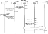
- FIG. 13 is a sequence diagram illustrating an example of the flow of a connection process executed in the wireless communication system 1 according to the present embodiment. As illustrated in FIG. 13 , the present sequence involves the base station 310, the WWAN terminal 200A, the WLAN terminal 100, and the WWAN terminal 200B. The present sequence corresponds to FIG. 2 and FIG. 4 .
- steps S302 to S310 a process similar to steps S102 to S110 illustrated in FIG. 10 is performed.
- link information may be omitted from information transmitted from the WWAN terminal 200A to the WWAN terminal 200B via the base station 310.
- step S312 the WWAN terminal 200B performs a network activation process.
- a connection destination selection policy of the WWAN terminal 200A be used in the present step.
- the WWAN terminal 200B activates the function as the base station 510 to form the WLAN 500.
- the WWAN terminal 200B may activate the function as the base station 510 while maintaining the WWAN communication function and the WLAN communication function, or may be restarted as an access-point-dedicated terminal.
- step S314 the base station 510 (namely, the WWAN terminal 200B serving as the base station 510) transmits a beacon to the surroundings.
- FIG. 13 illustrates the manner in which the WLAN terminal 100 has received the beacon transmitted from the base station 510 as a beacon relevant to the connection destination selection policy shared in the above-described step S304.
- the WLAN terminal 100 may identify whether the beacon is relevant to the connection destination selection policy in accordance with SSID.
- step S316 the WLAN terminal 100 performs an authentication process to the WLAN 500 using the subscriber identification information of the WWAN terminal 200.
- subscriber identification information of the WWAN terminal 200A is used.
- a message for an EAP authentication process is transmitted and received using the communication path established in the above-described step S302. The detailed process in the present step has been described above referring to FIG. 11 and FIG. 12 .
- connection between the WLAN terminal 100 and the base station 510 is established in step S318.
- the wireless communication apparatuses 100 and 200 may be implemented as a mobile terminal such as a smartphone, a tablet-type personal computer (PC), a notebook PC, a portable game terminal, or a digital camera, a fixed-type terminal such as a television receiver set, a printer, a digital scanner, or a network storage, or an in-vehicle terminal such as a car navigation apparatus.
- a mobile terminal such as a smartphone, a tablet-type personal computer (PC), a notebook PC, a portable game terminal, or a digital camera
- a fixed-type terminal such as a television receiver set, a printer, a digital scanner, or a network storage
- an in-vehicle terminal such as a car navigation apparatus.
- the wireless communication apparatuses 100 and 200 may be implemented as a terminal which performs machine-to-machine (M2M) communication (which is also referred to as a machine-type communication (MTC) terminal) such as a smart meter, a vending machine, a remote monitoring apparatus, or a point-of-sale (POS) terminal.
- M2M machine-to-machine
- MTC machine-type communication
- POS point-of-sale
- the wireless communication apparatuses 100 and 200 may be a wireless communication module (for example, an integrated circuit module configured in one die) mounted in these terminals.
- FIG. 14 is a block diagram illustrating an example of a schematic configuration of a smartphone 900 to which the technology of the present disclosure may be applied.
- the smartphone 900 includes a processor 901, a memory 902, a storage 903, an external connection interface 904, a camera 906, a sensor 907, a microphone 908, an input device 909, a display device 910, a speaker 911, a wireless communication interface 913, an antenna switch 914, an antenna 915, a bus 917, a battery 918, and an auxiliary controller 919.
- the processor 901 may be, for example, a central processing unit (CPU) or a system on a chip (SoC), and controls functions of an application layer and another layer of the smartphone 900.
- the memory 902 includes a random access memory (RAM) and a read only memory (ROM), and stores a program that is executed by the processor 901, and data.
- the storage 903 may include a storage medium such as a semiconductor memory or a hard disk.
- the external connection interface 904 is an interface for connecting an external device such as a memory card or a universal serial bus (USB) device to the smartphone 900.
- the camera 906 includes an image sensor such as a charge coupled device (CCD) and a complementary metal oxide semiconductor (CMOS), and generates a captured image.
- the sensor 907 may include a group of sensors such as a measurement sensor, a gyro sensor, a geomagnetic sensor, and an acceleration sensor.
- the microphone 908 converts sounds that are input to the smartphone 900 to audio signals.
- the input device 909 includes, for example, a touch sensor configured to detect touch onto a screen of the display device 910, a keypad, a keyboard, a button, or a switch, and receives an operation or an information input from a user.
- the display device 910 includes a screen such as a liquid crystal display (LCD) or an organic light-emitting diode (OLED) display, and displays an output image of the smartphone 900.
- the speaker 911 converts audio signals that are output from the smartphone 900 to sounds.
- the wireless communication interface 913 supports one or more of wireless LAN standards such as IEEE 802.11a, 11b, 11g, 11n, 11ac, and 11ad to execute wireless communication.
- the wireless communication interface 913 can communicate with another apparatus via a wireless LAN access point in an infrastructure mode.
- the wireless communication interface 913 can directly communicate with another apparatus in an ad hoc mode or a direct communication mode such as Wi-Fi direct (registered trademark), or the like.
- Wi-Fi Direct unlike the ad-hoc mode, one of two terminals operates as an access point, but communication is performed directly between the terminals.
- the wireless communication interface 913 can typically include a baseband processor, a radio frequency (RF) circuit, and a power amplifier.
- RF radio frequency
- the wireless communication interface 913 may be a one-chip module in which a memory which stores a communication control program, a processor which executes the program and a relevant circuit are integrated.
- the wireless communication interface 913 may support other kinds of wireless communication schemes such as a near field wireless communication scheme, a proximity wireless communication scheme or a cellular communication scheme in addition to the wireless LAN scheme.
- the antenna switch 914 switches connection destinations of the antenna 915 between a plurality of circuits (for example, circuits for different wireless communication schemes) included in the wireless communication interface 913.
- the antenna 915 has a single or a plurality of antenna elements (for example, a plurality of antenna elements which constitute a MIMO antenna), which are used by the wireless communication interface 913 for transmission and reception of radio signals.
- the smartphone 900 is not limited to the example of FIG. 14 and may include a plurality of antennas (for example, an antenna for a wireless LAN, or an antenna for the proximity wireless communication scheme, etc.). In that case, the antenna switch 914 may be omitted from the configuration of the smartphone 900.
- the bus 917 connects the processor 901, the memory 902, the storage 903, the external connection interface 904, the camera 906, the sensor 907, the microphone 908, the input device 909, the display device 910, the speaker 911, the wireless communication interface 913, and the auxiliary controller 919 to each other.
- the battery 918 supplies power to blocks of the smartphone 900 illustrated in FIG. 14 via feeder lines, which are partially shown as dashed lines in the figure.
- the auxiliary controller 919 operates a minimum necessary function of the smartphone 900, for example, in a sleep mode.
- one or more structural elements included in the WLAN terminal 100 described using FIG. 5 may be incorporated into the wireless communication interface 913. Moreover, at least some of these structural elements may be incorporated into the processor 901 or the auxiliary controller 919. As an example, a module including the wireless communication interface 913, the processor 901, and/or the auxiliary controller 919 may be mounted in the smartphone 900, and the above-described one or more structural elements may be incorporated into this module.
- the above-described module may store a program for causing the processor to function as the above-described one or more structural elements (in other words, a program for causing the processor to execute operations of the above-described one or more structural elements), and may execute the program.
- a program for causing the processor to function as the above-described one or more structural elements may be installed in the smartphone 900, and the wireless communication interface 913, the processor 901, and/or the auxiliary controller 919 may execute the program.
- the smartphone 900 or the above-described module may be provided as a device including the above-described one or more structural elements, and a program for causing the processor to function as the above-described one or more structural elements may be provided.
- a readable recording medium that stores the above-described program may be provided.
- one or more structural elements included in the WWAN terminal 200 described using FIG. 6 may be incorporated into the wireless communication interface 913.
- at least some of these structural elements may be incorporated into the processor 901 or the auxiliary controller 919.
- a module including the wireless communication interface 913, the processor 901, and/or the auxiliary controller 919 may be mounted in the smartphone 900, and the above-described one or more structural elements may be incorporated into this module.
- the above-described module may store a program for causing the processor to function as the above-described one or more structural elements (in other words, a program for causing the processor to execute operations of the above-described one or more structural elements), and may execute the program.
- a program for causing the processor to function as the above-described one or more structural elements may be installed in the smartphone 900, and the wireless communication interface 913, the processor 901, and/or the auxiliary controller 919 may execute the program.
- the smartphone 900 or the above-described module may be provided as a device including the above-described one or more structural elements, and a program for causing the processor to function as the above-described one or more structural elements may be provided.
- a readable recording medium that stores the above-described program may be provided.
- the smartphone 900 may operate as a wireless access point (software AP) by executing an access point function at an application level through the processor 901. Further, the wireless communication interface 913 may have a wireless access point function.
- FIG. 15 is a block diagram illustrating an example of a schematic configuration of a car navigation apparatus 920 to which the technology of the present disclosure may be applied.
- the car navigation apparatus 920 includes a processor 921, a memory 922, a global positioning system (GPS) module 924, a sensor 925, a data interface 926, a content player 927, a storage medium interface 928, an input device 929, a display device 930, a speaker 931, a wireless communication interface 933, an antenna switch 934, an antenna 935, and a battery 938.
- GPS global positioning system
- the processor 921 may be, for example, a CPU or a SoC, and controls a navigation function and another function of the car navigation apparatus 920.
- the memory 922 includes RAM and ROM, and stores a program that is executed by the processor 921, and data.
- the GPS module 924 uses GPS signals received from a GPS satellite to measure a position (such as latitude, longitude, and altitude) of the car navigation apparatus 920.
- the sensor 925 may include a group of sensors such as a gyro sensor, a geomagnetic sensor, and a barometric sensor.
- the data interface 926 is connected to, for example, an in-vehicle network 941 via a terminal that is not shown, and acquires data generated by the vehicle, such as vehicle speed data.
- the content player 927 reproduces content stored in a storage medium (such as a CD or a DVD) that is inserted into the storage medium interface 928.
- the input device 929 includes, for example, a touch sensor configured to detect touch onto a screen of the display device 930, a button, or a switch, and receives an operation or an information input from a user.
- the display device 930 includes a screen such as a LCD or an OLED display, and displays an image of the navigation function or content that is reproduced.
- the speaker 931 outputs sounds of the navigation function or the content that is reproduced.
- the wireless communication interface 933 supports one or more of wireless LAN standards such as IEEE 802.11a, 11b, 11g, 11n, 11ac, and 11ad to execute wireless communication.
- the wireless communication interface 933 can communicate with another apparatus via a wireless LAN access point in an infrastructure mode.
- the wireless communication interface 933 can directly communicate with another apparatus in an ad hoc mode or a direct communication mode such as Wi-Fi Direct.
- the wireless communication interface 933 can typically include a baseband processor, an RF circuit, and a power amplifier.
- the wireless communication interface 933 may be a one-chip module in which a memory which stores a communication control program, a processor which executes the program and a relevant circuit are integrated.
- the wireless communication interface 933 may support other kinds of wireless communication schemes such as a near field wireless communication scheme, a proximity wireless communication scheme or a cellular communication scheme in addition to the wireless LAN scheme.
- the antenna switch 934 switches connection destinations of the antenna 935 between a plurality of circuits included in the wireless communication interface 933.
- the antenna 935 has a single or a plurality of antenna elements, which are used by the wireless communication interface 933 for transmission and reception of radio signals.
- the car navigation apparatus 920 may include a plurality of antennas, not limited to the example of FIG. 15 . In that case, the antenna switches 934 may be omitted from the configuration of the car navigation apparatus 920.
- the battery 938 supplies power to blocks of the car navigation apparatus 920 illustrated in FIG. 15 via feeder lines that are partially shown as dashed lines in the figure.
- the battery 938 accumulates power supplied from the vehicle.
- one or more structural elements (for example, at least either the memory unit 120 or the control unit 130) included in the WLAN terminal 100 described using FIG. 5 may be incorporated into the wireless communication interface 933. Moreover, at least some of these functions may be incorporated into the processor 921. As an example, a module including the wireless communication interface 933 and/or the processor 921 may be mounted in the car navigation apparatus 920, and the above-described one or more structural elements may be incorporated into this module.
- the above-described module may store a program for causing the processor to function as the above-described one or more structural elements (in other words, a program for causing the processor to execute operations of the above-described one or more structural elements), and may execute the program.
- a program for causing the processor to function as the above-described one or more structural elements may be installed in the car navigation apparatus 920, and wireless communication interface 933 and/or the processor 921 may execute the program.
- the car navigation apparatus 920 or the above-described module may be provided as a device including the above-described one or more structural elements, and a program for causing the processor to function as the above-described one or more structural elements may be provided.
- a readable recording medium that stores the above-described program may be provided.
- one or more structural elements included in the WWAN terminal 200 described using FIG. 6 may be incorporated into the wireless communication interface 933. Moreover, at least some of these functions may be incorporated into the processor 921. As an example, a module including wireless communication interface 933 and/or the processor 921 may be mounted in the car navigation apparatus 920, and the above-described one or more structural elements may be incorporated into this module.
- the above-described module may store a program for causing the processor to function as the above-described one or more structural elements (in other words, a program for causing the processor to execute operations of the above-described one or more structural elements), and may execute the program.
- a program for causing the processor to function as the above-described one or more structural elements may be installed in the car navigation apparatus 920, and wireless communication interface 933 and/or the processor 921 may execute the program.
- the car navigation apparatus 920 or the above-described module may be provided as a device including the above-described one or more structural elements, and a program for causing the processor to function as the above-described one or more structural elements may be provided.
- a readable recording medium that stores the above-described program may be provided.
- the technology of the present disclosure may also be implemented as an in-vehicle system (or a vehicle) 940 including one or more blocks of the car navigation apparatus 920, the in-vehicle network 941, and a vehicle module 942.
- the vehicle module 942 generates vehicle data such as vehicle speed, engine speed, and trouble information, and outputs the generated data to the in-vehicle network 941.
- the WWAN terminal 200B capable of connecting to the WWAN 300 to perform wireless communication assists connection by the WLAN terminal 100 to the WLAN 500 corresponding to the connection destination selection policy of the WWAN terminal 200A received via the WWAN 300. This allows the WLAN terminal 100 to connect to the WLAN 500 because of the assistance by the WWAN terminal 200B even when it is not easy to connect to the WLAN 500 individually or even via the WWAN terminal 200A. In this manner, the WLAN terminal 100 can connect to a network more easily.
- the WWAN terminal 200B forms the WLAN 500 for oneself or causes the WLAN terminal 100 to connect to another WLAN 500, using the received connection destination selection policy. In any way, the WWAN terminal 200A does not perform tethering or relaying, which achieves a reduction in power consumption. Moreover, the WWAN terminal 200B does not perform tethering or relaying in the case of causing the WLAN terminal 100 to connect to another WLAN 500, which achieves a reduction in power consumption.
- the WLAN terminal 100 can perform an authentication process to the WLAN 500 using subscriber identification information of the WWAN terminal 200A or subscriber identification information of the WWAN terminal 200B. Therefore, even when the WLAN terminal 100 does not have subscriber identification information, the Internet can be utilized.
- a user of the WLAN terminal 100 may be able to utilize a service equivalent to or better than the service of one's own WWAN terminal 200A. For example, in the case where the communication speed of a service intended for the WWAN terminal 200B used by another person is 1 Mbps, the WLAN terminal 100 can utilize the service at 1 Mbps even if the communication speed of a service intended for its own WWAN terminal 200A is 500 kbps.
- a telecommunications carrier may provide the WWAN terminal 200B having permitted a request from the WLAN terminal 100 with an incentive, such as a discount on communication charges, and may carry out billing and settlement for the WLAN terminal 100.
- an incentive such as a discount on communication charges
- the present technology can also contribute to monetization by a telecommunications carrier.
- FIG. 2 illustrates an example in which the WWAN terminal 200B serves as the base station 510, whilst the present technology is not limited to such an example.
- a device serving as the base station 510 may be formed as a device separate from the WWAN terminal 200B.
- the WWAN terminal 200B may be selected on the basis of a connection destination selection policy of the WWAN terminal 200A.
- a WWAN terminal 200 having a similar connection destination selection policy or a WWAN terminal 200 close to a position indicated by information included in the connection destination selection policy may be chosen as the WWAN terminal 200B.
- present technology may also be configured as below.
Abstract
Description
- The present disclosure relates to a wireless communication apparatus, a wireless communication method, and a program.
- Recent years have seen various services using the Internet, and means for easily accessing the Internet even away from home have been demanded. For example, terminals with a wireless wide area network (WWAN) communication function, such as smartphones and mobile phones, can access the Internet via a mobile communication network even away from home. On the other hand, terminals without a WWAN communication function are required to access the Internet using other communication schemes, such as wireless local area network (WLAN). Connecting to a network (e.g., WLAN) may require processes such as searching for an access point and inputting an identifier (ID) and a password, which leads to demands for technologies for facilitating such processes.
- Here, in a case where direct communication between apparatuses cannot be performed easily, there is a technology of enabling communication between the apparatuses by interposing a relay station. For example,
Patent Literature 1 below discloses a technology of operating, as a relay station, a mobile station selected from among a plurality of mobile stations on the basis of received power or reception quality to relay communication by another mobile station. - Patent Literature 1:
JP 2011-29990A - There is so-called tethering as a technology of enabling access to the Internet by relaying communication by another wireless terminal by a relay station as disclosed in the above-described
Patent Literature 1. In tethering, however, there are various restrictions in which, for example, a terminal to be operated as a master device for tethering is generally limited to a terminal used by an identical user, so that access to the Internet by the terminal may not be performed easily. - Therefore, the present disclosure proposes a wireless communication apparatus, a wireless communication method, and a program being novel and improved by which connection to a network can be made more easily.
- According to the present disclosure, there is provided a wireless communication apparatus including: a first wireless communication unit configured to connect to a first network to perform wireless communication; and a control unit configured to assist connection, to a second network corresponding to a connection destination selection policy of another wireless communication apparatus received by the first wireless communication unit, by a wireless terminal related to the other wireless communication apparatus.
- Further, according to the present disclosure, there is provided a wireless communication apparatus including: a first wireless communication unit configured to connect to a first network to perform wireless communication; and a control unit configured to control the first wireless communication unit to transmit a connection destination selection policy via the first network to another wireless communication apparatus that assists connection to a second network by a wireless terminal related to the other wireless communication apparatus.
- Further, according to the present disclosure, there is provided a wireless communication method including: with a wireless communication apparatus configured to connect to a first network to perform wireless communication, assisting connection, to a second network corresponding to a received connection destination selection policy of another wireless communication apparatus, by a wireless terminal related to the other wireless communication apparatus.
- Further, according to the present disclosure, there is provided a wireless communication method including: with a wireless communication apparatus configured to connect to a first network to perform wireless communication, transmitting a connection destination selection policy via the first network to another wireless communication apparatus that assists connection to a second network by a wireless terminal related to the other wireless communication apparatus.
- Further, according to the present disclosure, there is provided a program for causing a computer to function as: a first wireless communication unit configured to connect to a first network to perform wireless communication; and a control unit configured to assist connection, to a second network corresponding to a connection destination selection policy of another wireless communication apparatus received by the first wireless communication unit, by a wireless terminal related to the other wireless communication apparatus.
- Further, according to the present disclosure, there is provided a program for causing a computer to function as: a first wireless communication unit configured to connect to a first network to perform wireless communication; and a control unit configured to control the first wireless communication unit to transmit a connection destination selection policy via the first network to another wireless communication apparatus that assists connection to a second network by a wireless terminal related to the other wireless communication apparatus.
- As described above, according to the present disclosure, connection to a network can be made more easily. Note that the effects described above are not necessarily limitative. With or in the place of the above effects, there may be achieved any one of the effects described in this specification or other effects that may be grasped from this specification.
-
- [
FIG. 1] FIG. 1 is a view for explaining an overview of a wireless communication system according to an embodiment of the present disclosure. - [
FIG. 2] FIG. 2 is a view for explaining an overview of a wireless communication system according to an embodiment of the present disclosure. - [
FIG. 3] FIG. 3 is a block diagram illustrating an example of a configuration of a wireless communication system according to the present embodiment. - [
FIG. 4] FIG. 4 is a block diagram illustrating an example of a configuration of a wireless communication system according to the present embodiment. - [
FIG. 5] FIG. 5 is a block diagram illustrating an example of a logical configuration of a WLAN terminal according to the present embodiment. - [
FIG. 6] FIG. 6 is a block diagram illustrating an example of a logical configuration of a WWAN terminal according to the present embodiment. - [
FIG. 7] FIG. 7 is a view illustrating an example of a UI in the WWAN terminal according to the present embodiment. - [
FIG. 8] FIG. 8 is an explanatory diagram for explaining an example of a connection destination selection policy according to the present embodiment. - [
FIG. 9] FIG. 9 is an explanatory diagram for explaining an example of positional information according to the present embodiment. - [
FIG. 10] FIG. 10 is a sequence diagram illustrating an example of the flow of a connection process executed in a wireless communication system according to the present embodiment. - [
FIG. 11] FIG. 11 is a sequence diagram illustrating an example of the flow of an EAP authentication process executed in the wireless communication system according to the present embodiment. - [
FIG. 12] FIG. 12 is a sequence diagram illustrating an example of the flow of an EAP authentication process executed in the wireless communication system according to the present embodiment. - [
FIG. 13] FIG. 13 is a sequence diagram illustrating an example of the flow of a connection process executed in a wireless communication system according to the present embodiment. - [
FIG. 14] FIG. 14 is a block diagram illustrating an example of a schematic configuration of a smartphone. - [
FIG. 15] FIG. 15 is a block diagram illustrating an example of a schematic configuration of a car navigation apparatus. - Hereinafter, (a) preferred embodiment(s) of the present disclosure will be described in detail with reference to the appended drawings. In this specification and the appended drawings, structural elements that have substantially the same function and structure are denoted with the same reference numerals, and repeated explanation of these structural elements is omitted.
- Also, in this specification and the appended drawings, elements having substantially the same function and structure may in some cases be distinguished by different letters appended to the same reference sign. For example, multiple elements having substantially the same function and structure are distinguished as WWAN
terminals terminals terminals terminal 200. - Note that description will be provided in the following order.
- 1. Overview
- 1. 1. Schematic system configuration
- 1. 2. Technical problems
- 2. Configuration examples
- 2. 1. Configuration example of wireless communication system
- 2. 2. Configuration example of WLAN terminal
- 2. 3. Configuration example of WWAN terminal
- 3. Technical features
- 4. Example of operation and process
- 5. Applications
- 6. Conclusion
- First, referring to
FIG. 1 andFIG. 2 , an overview of awireless communication system 1 according to an embodiment of the present disclosure will be described. -
FIG. 1 andFIG. 2 are views for explaining an overview of thewireless communication system 1 according to an embodiment of the present disclosure. In the example illustrated inFIG. 1 andFIG. 2 , thewireless communication system 1 includes awireless communication apparatus 100 and wireless communication apparatuses 200 (200A and 200B). - The
wireless communication apparatus 100 is a wireless terminal capable of wirelessly communicating with another apparatus. In the example ofFIG. 1 andFIG. 2 , thewireless communication apparatus 100 is a notebook PC. Thewireless communication apparatus 100 is a WLAN terminal that can connect to a WLAN according to a communication scheme, such as Institute of Electrical and Electronics Engineers (IEEE) 802.11a, 11b, 11g, 11n, 11ac, or 11ad. As illustrated inFIG. 1 , theWLAN terminal 100 can connect to awireless network 500 via abase station 510, and use a service provided by aservice network 400. In addition, theWLAN terminal 100 can establish wireless connection with thewireless communication apparatus 200. This wireless connection can be established according to any communication scheme, such as Bluetooth (registered trademark) or near field communication (NFC). TheWLAN terminal 100 can connect to a WLAN whose network information is known, such as a WLAN operated at a user's home, for example, but cannot easily connect to a WLAN whose network information is unknown, such as a WLAN away from home. Note that thewireless communication apparatus 100 may be implemented as, as well as a notebook PC, a PC, a tablet terminal, personal digital assistants (PDA), a head mounted display (HMD), a headset, a digital camera, a digital video camera, a smartphone, a mobile phone terminal, a portable music player, a portable video processor, or a portable game device. - The
wireless communication apparatus 200 is a wireless terminal capable of wirelessly communicating with another apparatus. In the example ofFIG. 1 andFIG. 2 , thewireless communication apparatus 200 is a smartphone. Thewireless communication apparatus 200 can establish wireless connection with theWLAN terminal 100, for example. In addition, thewireless communication apparatus 200 is a WWAN terminal that has a WWAN communication function and can connect to a WWAN. TheWWAN terminal 200 has subscriber identification information for connection to a mobile communication network, and performs an authentication process using the subscriber identification information to establish wireless connection with a wireless network 300 (e.g., mobile communication network). The subscriber identification information is, for example, international mobile subscriber identity (IMSI) stored in a subscriber identity module card (SIM card). TheWWAN terminal 200 can connect to thewireless network 300 using the WWAN communication function, and use a service provided by aservice network 400. Note that thewireless communication apparatus 200 may be implemented as, as well as a smartphone, a notebook PC, a PC, a tablet terminal, PDA, a HMD, a headset, a digital camera, a digital video camera, a mobile phone terminal, a portable music player, a portable video processor, or a portable game device. - Here, it is assumed that the
WWAN terminal 200A is a terminal related to theWLAN terminal 100. For example, theWWAN terminal 200A may be previously subjected to association, such as pairing with theWLAN terminal 100. For example, theWWAN terminal 200A is used by a user identical to the user of theWLAN terminal 100. On the other hand, it is assumed that theWWAN terminal 200B is a terminal not related to theWLAN terminal 100. For example, theWWAN terminal 200B is used by a user different from the user of theWLAN terminal 100. - The
wireless network 300 is a WWAN (first network), such as a mobile communication network. For example, theWWAN 300 is operated according to any wireless communication scheme, such as Long Term Evolution (LTE), LTE-Advanced (LTE-A), GSM (registered trademark), UMTS, W-CDMA, or CDMA2000. For example, thewireless communication apparatus 200 located within a range of a cell operated by abase station 310 connects to theWWAN 300. - The
service network 400 is a public network, such as the Internet. TheWWAN terminal 200 can access theservice network 400 via theWWAN 300. - Here, a terminal without a WWAN communication function cannot easily access the Internet via the
WWAN 300. Even in such as case, as a means of accessing the Internet away from home, for example, tethering by a terminal capable of WWAN communication may be performed, or a public WLAN may be used, for example. - Tethering is a technology in which, via a terminal with a WWAN communication function, such as a smartphone, another communication terminal connects to a
WWAN 300. For example, theWWAN terminal 200 is connectable to theWWAN 300 and theWLAN terminal 100, therefore, theWWAN terminal 200 can serve as an access point that relays communication between theWWAN 300 and theWLAN terminal 100, thus enabling tethering. This allows theWLAN terminal 100 to use a service provided by theservice network 400. - Tethering is available regardless of where the
WWAN terminal 200 is located in a WWAN communication available area. However, terminal setting for using tethering is required to be performed in both theWWAN terminal 200 and theWLAN terminal 100, which leads to poor user convenience. Moreover, during tethering, theWWAN terminal 200 serving as an access point consumes a large amount of power. - Meanwhile, a public WLAN is a service that provides connection to the Internet using a WLAN. A
wireless network 500 is a public network (second network) operated by a WLAN, for example. TheWLAN terminal 100 can connect to theWLAN 500 to access theservice network 400, or to access theservice network 400 further via theWWAN 300. This allows theWLAN terminal 100 to use a service provided by theservice network 400. Note that, in the example illustrated inFIG. 1 , theWLAN 500 is operated by thebase station 510, and in the example illustrated inFIG. 2 , theWLAN 500 is operated by theWWAN terminal 200B serving as thebase station 510. - Here, a wireless terminal with a WWAN communication function, such as a smartphone, can connect to a surrounding public WLAN and perform user authentication using its own subscriber identification information, by using a technology of access network discovery and selection function (ANDSF) proposed by Third Generation Partnership Project (3GPP) or Wi-Fi CERTIFIED Passpoint proposed by Wi-Fi Alliance. However, a wireless terminal without a WWAN communication function, like a notebook PC, not having subscriber identification information, may require a user to select an available public WLAN for oneself and perform an authentication procedure, which leads to poor convenience.
- Meanwhile, the
WLAN terminal 100 can access the Internet by operating theWWAN terminal 200A in the tethering mode. However, theWLAN terminal 100 cannot use the Internet easily in a case where theWWAN terminal 200A is not adaptable to the tethering mode or in a case where restrictions are imposed on the data communication speed or data traffic even if theWWAN terminal 200A is adaptable to tethering. In addition, theWWAN terminal 200B cannot be operated easily in the tethering mode for theWLAN terminal 100 since theWWAN terminal 200B is used by a different user, for example. - Therefore, using the above-described circumstances as a viewpoint, a wireless communication apparatus according to an embodiment of the present disclosure has been created. The wireless communication apparatus according to an embodiment of the present disclosure is capable of connecting to a network more easily. Specifically, an embodiment of the present disclosure provides a mechanism in which the
WLAN terminal 100 is capable of connecting to the Internet with involvement of the WWAN terminal 200B used by another user. For example, inFIG. 1 , theWWAN terminal 200B assists an authentication process to theWLAN 500 by theWLAN terminal 100. On the other hand, inFIG. 2 , theWWAN terminal 200B, by serving as thebase station 510 for oneself, assists connection to theWLAN 500 by theWLAN terminal 100. - Hereinafter, referring to
FIG. 3 to FIG. 15 , a wireless communication system including a wireless communication apparatus according to an embodiment of the present disclosure will be described in detail. -
FIG. 3 andFIG. 4 are block diagrams illustrating an example of a configuration of thewireless communication system 1 according to the present embodiment. As shown inFIG. 3 andFIG. 4 , thewireless communication system 1 includes theWLAN terminal 100 and theWWAN terminal 200, and provides wireless communication to theWWAN 300, theWLAN 500, and theservice network 400. Note thatFIG. 3 is a configuration example corresponding toFIG. 1 , andFIG. 4 is a configuration example corresponding toFIG. 2 . Note that illustration of theWWAN terminal 200A is omitted inFIG. 4 as it is similar to the configuration shown inFIG. 3 . - As illustrated in
FIG. 3 andFIG. 4 , theWWAN 300 is operated by thebase station 310, agateway 320, asubscriber information server 330, anauthentication server 340, and a networkinformation providing server 350. - The
base station 310 serves as a contact when a wireless terminal with a WWAN communication function connects to theWWAN 300. For example, thebase station 310 accepts connection from theWWAN terminal 200. In LTE, thebase station 310 corresponds to an eNB. - The
gateway 320 relays communication between theWWAN 300 and another network. For example, thegateway 320 relays communication between theWWAN 300 and theservice network 400, and communication between theWWAN 300 and theWLAN 500. In LTE, thegateway 320 corresponds to a packet data network gateway (P-GW). - The
subscriber information server 330 retains subscriber information for theWWAN 300. Thesubscriber information server 330 also retains information used for an authentication process when a wireless terminal connects to theWWAN 300. In LTE, thesubscriber information server 330 corresponds to a home subscriber server (HSS). - The
authentication server 340 authenticates that connection to theWWAN 300 is connection by a subscriber of theWWAN 300. Theauthentication server 340 may perform this authentication process referring to thesubscriber information server 330. In LTE, theauthentication server 340 corresponds to an authentication, authorization and accounting (AAA) server. - Moreover, the
authentication server 340 has a function of authenticating connection to theWLAN 500. For example, as an authentication protocol to theWLAN 500, an authentication protocol by means of subscriber identification information to theWWAN 300, such as extensible authentication protocol (EAP)-AKA, EAP-SIM, or EAP-AKA', may be employed. In that case, theauthentication server 340 performs an authentication process referring to thesubscriber information server 330. Note that a terminal with the WWAN communication function capable of connecting to theWWAN 300 through an authentication process by means of subscriber identification information is capable of connecting to theWLAN 500 likewise through an authentication process by means of subscriber identification information. - The network
information providing server 350 provides information on a wireless network that is a connection destination, which is needed in switching a connection destination from a wireless network to which a wireless terminal is connected currently to another wireless network. For example, the networkinformation providing server 350 may provide theWWAN terminal 200 with network information for connecting to theWLAN 500. In LTE, the networkinformation providing server 350 corresponds to an ANDSF server. - The
WLAN 500 is a public network operated by abase station 510. In this specification, a communication scheme of the public network is described to be WLAN, but the public network may be operated according to any other communication scheme, such as Bluetooth. - The
base station 510 serves as a contact when a wireless terminal with a WLAN communication function connects to theWLAN 500. For example, thebase station 510 accepts connection from theWLAN terminal 100. In the case where a communication scheme of the public network is WLAN, thebase station 510 corresponds to an access point. Note that thebase station 510 may support one or more authentication protocols. In the example illustrated inFIG. 3 , theWLAN 500 is operated by thebase station 510. On the other hand, in the example illustrated inFIG. 4 , theWLAN 500 is operated by theWWAN terminal 200B serving as thebase station 510. -
FIG. 5 is a block diagram illustrating an example of a logical configuration of theWLAN terminal 100 according to the present embodiment. As illustrated inFIG. 5 , theWLAN terminal 100 includes awireless communication unit 110, amemory unit 120, and acontrol unit 130. - The
wireless communication unit 110 is a communication module that transmits and receives data to/from an external device. Thewireless communication unit 110 can perform wireless communication using various communication schemes. For example, thewireless communication unit 110 includes aWLAN module 112 and is capable of wireless communication using Wi-Fi (registered trademark), or WLAN. Thewireless communication unit 110 also includes a Bluetooth (BT)module 114 and is capable of wireless communication using Bluetooth. Thewireless communication unit 110 also includes anNFC module 116 and is capable of wireless communication using NFC. - For example, the
wireless communication unit 110 performs wireless communication with theWWAN terminal 200. For example, thewireless communication unit 110 may perform wireless communication with theWWAN terminal 200 by using a near field wireless communication scheme, such as NFC, Bluetooth, Bluetooth low energy, Wi-Fi direct (registered trademark), WLAN, or the like. Besides, thewireless communication unit 110 may perform wireless communication with theWWAN terminal 200 by using a near field wireless communication scheme, such as ZigBee (registered trademark), infrared data association (IrDA), or the like. - For example, the
wireless communication unit 110 connects to a public network to perform wireless communication. For example, thewireless communication unit 110 connects to theWLAN 500 using a wireless communication scheme, such as WLAN. The public network may support any wireless communication scheme other than WLAN, and in that case, thewireless communication unit 110 may connect to the public network using a wireless communication scheme corresponding to the public network. Thewireless communication unit 110 may also perform a measurement process of, for example, measuring a received signal strength indicator (RSSI) from the intensity of a signal received from theWLAN 500. - The
wireless communication unit 110 may perform wireless communication with theWWLAN terminal 200 and a public network by using the same communication scheme. For example, thewireless communication unit 110 may communicate with theWWAN terminal 200 by using a WLAN and connect to theWLAN 500. - The
memory unit 120 performs recording and reproduction of data on a predetermined recording medium. For example, thememory unit 120 may store a connection destination selection policy shared with theWWAN terminal 200A. - The
control unit 130 serves as an arithmetic processor and a controller, and controls the overall operation in theWLAN terminal 100 according to various programs. For example, thecontrol unit 130 performs various processes for connecting to theWLAN 500 on the basis of assistance by theWWAN terminal 200B. - A configuration example of the
WLAN terminal 100 according to the present embodiment has been described above. Subsequently, a configuration example of theWWAN terminal 200 according to the present embodiment will be described with reference toFIG. 6 . -
FIG. 6 is a block diagram illustrating an example of a logical configuration of theWWAN terminal 200 according to the present embodiment. As illustrated inFIG. 6 , theWWAN terminal 200 includes awireless communication unit 210, amemory unit 220, asubscriber identification module 230, and acontrol unit 240. Note that theWWAN terminals - The
wireless communication unit 210 is a communication module that transmits and receives data to/from an external device. Thewireless communication unit 210 can perform wireless communication using various communication schemes. For example, thewireless communication unit 210 includes aWWAN module 212 and is capable of wireless communication using theWWAN 300. Thewireless communication unit 210 also includes aWLAN module 214 and is capable of wireless communication using Wi-Fi, or WLAN. Thewireless communication unit 210 also includes aBT module 216 and is capable of wireless communication using Bluetooth. Thewireless communication unit 210 also includes anNFC module 218 and is capable of wireless communication using NFC. - For example, by means of the
WWAN module 212, thewireless communication unit 210 may serve as a first wireless communication unit that connects to theWWAN 300 to perform wireless communication. For example, thewireless communication unit 210 performs communication with theauthentication server 340 via theWWAN module 212. - For example, by means of the
WLAN module 214, thewireless communication unit 210 may serve as a second wireless communication unit that performs wireless communication concerning theWLAN 500. For example, thewireless communication unit 210 of theWWAN terminal 200A may perform communication with thebase station 510 via theWLAN module 214. In addition, thewireless communication unit 210 of the WWAN terminal 200B may form theWLAN 500 to perform wireless communication with theWLAN terminal 100. - For example, the
wireless communication unit 210 can serve as a third wireless communication unit that performs wireless communication with theWLAN terminal 100. For example, thewireless communication unit 210 can perform wireless communication with theWLAN terminal 100 using a near field wireless communication scheme, such as NFC, Bluetooth, Bluetooth low energy, Wi-Fi direct, WLAN, or the like. Besides, thewireless communication unit 210 may perform wireless communication with theWLAN terminal 100 using a near field wireless communication scheme, such as ZigBee, infrared data association (IrDA), or the like. - The
memory unit 220 performs recording and reproduction of data on a predetermined recording medium. For example, thememory unit 220 may store a connection destination selection policy, link information for establishing a link with theWLAN terminal 100, and the like. - The
subscriber identification module 230 serves as a storage unit that stores subscriber identification information for theWWAN 300. For example, thesubscriber identification module 230 is implemented by a SIM card. - The
control unit 240 serves as an arithmetic processor and a controller, and controls the overall operation in theWWAN terminal 200 according to various programs. For example, thecontrol unit 240 performs various processes for achieving connection to theWLAN 500 by theWLAN terminal 100. Specifically, thecontrol unit 240 of theWWAN terminal 200B assists connection by theWLAN terminal 100 to theWLAN 500 corresponding to a connection destination selection policy of theWWAN terminal 200A received by thewireless communication unit 210. This allows theWLAN terminal 100 to connect to theWLAN 500. In addition, thecontrol unit 240 of theWWAN terminal 200A controls thewireless communication unit 210 to transmit a connection destination selection policy via theWWAN 300 to the WWAN terminal 200B that assists connection to theWLAN 500 by theWLAN terminal 100. This allows theWWAN terminal 200B to acquire the connection destination selection policy. - A configuration example of the
WWAN terminal 200 according to the present embodiment has been described above. Subsequently, technical features of thewireless communication system 1 according to the present embodiment will be described. - The
WWAN terminal 200A requests assistance for connection to theWLAN 500 by theWLAN terminal 100. Specifically, theWWAN terminal 200A may transmit a connection destination selection policy as a request for assistance. The transmitted connection destination selection policy is received by the WWAN terminal 200B chosen by thewireless communication system 1 via theWWAN 300 and is used for assistance. This connection destination selection policy may be previously shared between theWWAN terminal 200A and theWLAN terminal 100. - The connection destination selection policy can be shared at various timings. For example, the connection destination selection policy may be shared at the timing of transmission from the ANDSF server to the
WWAN terminal 200A periodically per hour, per day, per week, or the like, or may be shared at the timing of power on/off of theWWAN terminal 200A, or may be shared at the timing when theWWAN terminal 200A has moved to a certain area. - The connection destination selection policy is information including information concerning a communication scheme of a network, priority of the network, and identification information of the network. A detailed structure of the connection destination selection policy will be described later referring to
FIG. 8 . As an example, an example in which, regarding ANDSF Management Object having the name of NetworkSelectionPolicy, there are two types of Policy, Set_1and Set 2, and priority is determined by RulePriority will be described below. Note that Set_1includes three pieces of access network information, whose priorities are each set by AccessNetworkPriority.
           ./ANDSF/Name=NetworkSelectionPolicy
           ./ANDSF/Policy/Set_1RulePriority=1
           ./ANDSF/Policy/Set_1PrioritizedAccess/1AccessTechnology=WLAN
           ./ANDSF/Policy/Set_1/PrioritizedAccess/1/AccessID=HotSpotSSID1
           ./ANDSF/Policy/Set_1/PrioritizedAccess/1/AccessNetworkPriority=10
           ./ANDSF/Policy/Set_1/PrioritizedAccess/2/AccessTechnology=WLAN
           ./ANDSF/Policy/Set_1/PrioritizedAccess/2/AccessID=HotSpotSSID2
           ./ANDSF/Policy/Set_1/PrioritizedAccess/2/AccessNetworkPriority=20
           ./ANDSF/Policy/Set_1/PrioritizedAccess/3/AccessTechnology=WLAN
           ./ANDSF/Policy/Set_1/PrioritizedAccess/3/AccessID=HotSpotSSID3
           ./ANDSF/Policy/Set_1/PrioritizedAccess/3/AccessNetworkPriority=30
           ./ANDSF/Policy/Set_2/RulePriority=2
           ./AND SF/Policy/Set_2/PrioritizedAccess/1/AccessTechnology=WLAN
           ./ANDSF/Policy/Set_2/PrioritizedAccess/1/AccessID=HomeSSID
           ./ANDSF/Policy/Set_2/PrioritizedAccess/1/AccessNetworkPriority=10
- 0: Reserved
- 1: 3GPP
- 2: Reserved
- 3: WLAN
- 4: WiMAX
- 5-255: Reserved
- 0: Reserved
- 1-250: Priority value
- 251-253: Reserved
- 254: Limited access. Access should not be made when the current rule is valid.
- 255: Prohibited. UE should not make access when the current rule is valid.
- 0: unnecessary to update UE
- 1: necessary to update UE
<MCC: 3 digits><MNC: 2 or 3 digits><MSIN: 10 digits at maximum>
0<IMSI>@wlan.mnc<MNC>.mcc<MCC>.3gppnetwork.org
AUTN: A value for a terminal to authenticate a network.
XRES: A response value expected in response to a challenge.
IK: Message integrity verification key.
CK: Message encryption key.
- (1) A wireless communication apparatus including:
- a first wireless communication unit configured to connect to a first network to perform wireless communication; and
- a control unit configured to assist connection, to a second network corresponding to a connection destination selection policy of another wireless communication apparatus received by the first wireless communication unit, by a wireless terminal related to the other wireless communication apparatus.
- (2) The wireless communication apparatus according to (1), further including:
- a second wireless communication unit configured to form the second network to perform wireless communication with the wireless terminal,
- in which the control unit controls the second wireless communication unit to form the second network in a case where the connection destination selection policy is received.
- (3) The wireless communication apparatus according to (2),
in which the connection destination selection policy includes information concerning a communication scheme, priority, and identification information. - (4) The wireless communication apparatus according to (3),
in which the control unit controls the second wireless communication unit to form the second network using high-priority identification information included in the connection destination selection policy. - (5) The wireless communication apparatus according to any one of (2) to (4),
in which the second wireless communication unit forms the second network as an access point of a wireless LAN or as a P2P Group Owner of Wi-Fi Direct (registered trademark). - (6) The wireless communication apparatus according to any one of (2) to (5),
in which the control unit controls the first wireless communication unit and the second wireless communication unit to relay communication between the wireless terminal and the first network. - (7) The wireless communication apparatus according to (1),
in which the control unit selects a connection destination of the wireless terminal on the basis of the connection destination selection policy. - (8) The wireless communication apparatus according to (7),
in which the control unit selects the connection destination of the wireless terminal further on the basis of the connection destination selection policy of the wireless communication apparatus. - (9) The wireless communication apparatus according to (7) or (8),
in which the first wireless communication unit receives link information used for establishing a link with the wireless terminal. - (10) The wireless communication apparatus according to (9),
in which the link information includes identification information for identifying the wireless terminal. - (11) The wireless communication apparatus according to (9) or (10), further including:
- a storage unit configured to store subscriber identification information for the first network; and
- a third wireless communication unit configured to perform wireless communication with the wireless terminal using the link information,
- in which the control unit generates authentication information for extensible authentication protocol (EAP) authentication to the second network by the wireless terminal using the subscriber identification information stored in the storage unit, and transmits the authentication information to the wireless terminal by the third wireless communication unit.
- (12) The wireless communication apparatus according to any one of (1) to (11),
in which the first network is a mobile communication network, and
the second network is a public wireless LAN. - (13) A wireless communication apparatus including:
- a first wireless communication unit configured to connect to a first network to perform wireless communication; and
- a control unit configured to control the first wireless communication unit to transmit a connection destination selection policy via the first network to another wireless communication apparatus that assists connection to a second network by a wireless terminal related to the other wireless communication apparatus.
- (14) The wireless communication apparatus according to (13),
in which in a case where the second network exists in a neighborhood, the control unit controls the first wireless communication unit to transmit link information used for establishing a link with the wireless terminal. - (15) The wireless communication apparatus according to (13) or (14), further including:
- a storage unit configured to store subscriber identification information for the first network; and
- a third wireless communication unit configured to perform wireless communication with the wireless terminal,
- in which the control unit generates authentication information for EAP authentication to the second network by the wireless terminal using the subscriber identification information stored in the storage unit, and transmits the authentication information to the wireless terminal by the third wireless communication unit.
- (16) The wireless communication apparatus according to any one of (13) to (15),
in which the control unit controls the first wireless communication unit to transmit positional information of the wireless communication apparatus. - (17) A wireless communication method including:
with a wireless communication apparatus configured to connect to a first network to perform wireless communication, assisting connection, to a second network corresponding to a received connection destination selection policy of another wireless communication apparatus, by a wireless terminal related to the other wireless communication apparatus. - (18) A wireless communication method including:
with a wireless communication apparatus configured to connect to a first network to perform wireless communication, transmitting a connection destination selection policy via the first network to another wireless communication apparatus that assists connection to a second network by a wireless terminal related to the other wireless communication apparatus. - (19) A program for causing a computer to function as:
- a first wireless communication unit configured to connect to a first network to perform wireless communication; and
- a control unit configured to assist connection, to a second network corresponding to a connection destination selection policy of another wireless communication apparatus received by the first wireless communication unit, by a wireless terminal related to the other wireless communication apparatus.
- (20) A program for causing a computer to function as:
- a first wireless communication unit configured to connect to a first network to perform wireless communication; and
- a control unit configured to control the first wireless communication unit to transmit a connection destination selection policy via the first network to another wireless communication apparatus that assists connection to a second network by a wireless terminal related to the other wireless communication apparatus.
- 1
- wireless communication system
- 100
- WLAN terminal
- 110
- wireless communication unit
- 112
- WLAN module
- 114
- BT module
- 116
- NFC module
- 120
- memory unit
- 130
- control unit
- 200
- WWAN terminal
- 210
- wireless communication unit
- 212
- WWAN module
- 214
- WLAN module
- 216
- BT module
- 218
- NFC module
- 220
- memory unit
- 230
- subscriber identification module
- 240
- control unit
- 300
- WWAN
- 310
- base station
- 320
- gateway
- 330
- subscriber information server
- 340
- authentication server
- 341
- communication unit
- 342
- memory unit
- 343
- control unit
- 350
- network information providing server
- 400
- service network
- 500
- WLAN
- 510
- base station
Claims (15)
- A wireless wide area network, WWAN, terminal (200B) comprising:a wireless communication unit (212) configured to receive SSID information (S110) for a second network from another WWAN terminal (200A), to send a connection request (S112) to a wireless local area network, WLAN, terminal (100), and to establish a direct wireless connection (S114) between the WWAN terminal (200B) in a first network (300) and the WLAN terminal (100) based on the connection request; anda control unit (240) configured to assist connection between the WLAN terminal (100) and a WLAN base station (510) in the second network (500) by sending user information (S212) of the WWAN terminal (200B) or the another WWAN terminal (200A), the SSID information (S116) for the second network and authentication information (S232) to the WLAN terminal (100).
- The WWAN terminal according to claim 1, further comprising
a second wireless communication unit (214) configured to form the second network (500) to perform wireless communication with the WLAN terminal (100),
wherein the control unit (240) is configured to control the second wireless communication unit (214) to form the second network in a case where a connection destination selection policy is received, in particular the connection destination selection policy including information concerning a communication scheme, priority, and identification information. - The WWAN terminal (200B) according to claim 2,
wherein the control unit (240) is configured to control the second wireless communication unit to form the second network (500) using high-priority identification information included in the connection destination selection policy. - The WWAN terminal (200B) according to any one of claims 2 or 3,
wherein the second wireless communication unit (214) is configured to form the second network (500) as an access point of a wireless LAN or as a P2P Group Owner of Wi-Fi Direct. - The WWAN terminal (200B) according to any one of claims 2 to 4,
wherein the control unit (240) is configured to control the first wireless communication unit and the second wireless communication unit to relay communication between the WLAN terminal (100) and the first network (300). - The WWAN terminal (200B) according to claim 1,
wherein the control unit (240) is configured to select a connection destination of the WLAN terminal (100) on the basis of the connection destination selection policy, in particular on the basis of the connection destination selection policy of the wireless communication apparatus. - The WWAN terminal (200B) according to claim 6,
wherein the first wireless communication unit (212) is configured to receive link information used for establishing a link with the WLAN terminal (100), the link information in particular including identification information for identifying the WLAN terminal (100). - The WWAN terminal (200B) according to claim 7, further comprising:a storage unit (220) configured to store the user information, wherein the user information corresponds to subscriber identification information for the first network (300); anda third wireless communication unit (216, 218) configured to perform wireless communication with the WLAN terminal (100) using the link information;wherein the control unit (240) is configured to generate authentication protocol information for extensible authentication protocol (EAP) authentication to the second network (500) by the WLAN terminal (100) using the subscriber identification information stored in the storage unit, and transmit the authentication protocol information to the WLAN terminal (100) by the third wireless communication unit.
- The WWAN terminal according to any one of claims 1 to 8,
wherein the first network (300) is a mobile communication network, and
the second network is a public wireless LAN. - A wireless communication method comprising:receiving SSID information (S110) for a second network from another WWAN terminal (200A), sending a connection request (S112) to a WLAN terminal (100),establishing a direct wireless connection (S114) between a WWAN terminal (200B) in a first network (300) and the WLAN terminal based on the connection request, andcontrolling to assist connection between the WLAN terminal (100) and a WLAN base station (510) in the second network (500) by sending user information (S212) of the WWAN terminal (200B) or the another WWAN terminal (200A), the SSID information (S116) for the second network and authentication information (S232) to the WLAN terminal (100).
- A wireless local area network, WLAN, terminal (100) comprising:a wireless communication unit (110) configured to receive a connection request (S112) from a wireless wide area network, WWAN, terminal (200B), and to establish a direct wireless connection (S114) between the WWAN terminal (200B) in a first network (300) and the WLAN terminal (100) based on the connection request;a control unit (130) configured to perform a process for connecting to a WLAN base station (510) in a second network (500) on the basis of assistance by the WWAN terminal (200B),wherein the wireless communication unit (212) is further configured to receive user information (S212) of the WWAN terminal (200B) or the another WWAN terminal (200A), SSID information (S116) for the second network and authentication information (S232) from the WWAN terminal (200B).
- The WLAN terminal (100) according to claim 11,
wherein the wireless communication unit (110) is configured to receive link information used for establishing a link with the WWAN terminal (200B). - The WLAN terminal (100) according to claim 11 or 12,
wherein the wireless communication unit (110) is configured perform wireless communication with the WWAN terminal (200B) and to receive authentication protocol information from the WWAN terminal (200B) for EAP authentication to the second network by the wireless terminal. - A wireless communication method comprising:receiving a connection request (S112) from a wireless wide area network, WWAN, terminal (200B),establishing a direct wireless connection (S114) between the WWAN terminal (200B) in a first network (300) and the WLAN terminal (100) based on the connection request,performing a process for connecting to a WLAN base station (510) in a second network (500) on the basis of assistance by the WWAN terminal (200B), andreceiving user information (S212) of the WWAN terminal (200B) or the another WWAN terminal (200A), SSID information (S116) for the second network and authentication information (S232) from the WWAN terminal (200B).
- A program for causing a computer to carry out the steps of the method defined in claim 10 or 14 when said program is executed on the computer.
Applications Claiming Priority (3)
| Application Number | Priority Date | Filing Date | Title |
|---|---|---|---|
| JP2015022448 | 2015-02-06 | ||
| EP15881173.7A EP3255952B1 (en) | 2015-02-06 | 2015-11-05 | Wireless communication device, wireless communication method and program |
| PCT/JP2015/081226 WO2016125356A1 (en) | 2015-02-06 | 2015-11-05 | Wireless communication device, wireless communication method and program |
Related Parent Applications (2)
| Application Number | Title | Priority Date | Filing Date |
|---|---|---|---|
| EP15881173.7A Division-Into EP3255952B1 (en) | 2015-02-06 | 2015-11-05 | Wireless communication device, wireless communication method and program |
| EP15881173.7A Division EP3255952B1 (en) | 2015-02-06 | 2015-11-05 | Wireless communication device, wireless communication method and program |
Publications (2)
| Publication Number | Publication Date |
|---|---|
| EP3709765A1 true EP3709765A1 (en) | 2020-09-16 |
| EP3709765B1 EP3709765B1 (en) | 2023-04-26 |
Family
ID=56563714
Family Applications (2)
| Application Number | Title | Priority Date | Filing Date |
|---|---|---|---|
| EP15881173.7A Active EP3255952B1 (en) | 2015-02-06 | 2015-11-05 | Wireless communication device, wireless communication method and program |
| EP20172064.6A Active EP3709765B1 (en) | 2015-02-06 | 2015-11-05 | Wireless communication apparatus, wireless communication method, and program |
Family Applications Before (1)
| Application Number | Title | Priority Date | Filing Date |
|---|---|---|---|
| EP15881173.7A Active EP3255952B1 (en) | 2015-02-06 | 2015-11-05 | Wireless communication device, wireless communication method and program |
Country Status (4)
| Country | Link |
|---|---|
| US (1) | US10813155B2 (en) |
| EP (2) | EP3255952B1 (en) |
| JP (2) | JP6665791B2 (en) |
| WO (1) | WO2016125356A1 (en) |
Families Citing this family (4)
| Publication number | Priority date | Publication date | Assignee | Title |
|---|---|---|---|---|
| EP3893595B1 (en) * | 2016-12-09 | 2023-12-13 | Huawei Technologies Co., Ltd. | Establishment by a second terminal device of a wlan hotspot connection to a first terminal device for connecting to the internet |
| JP6521123B1 (en) * | 2018-02-28 | 2019-05-29 | 日本電気株式会社 | Communication control system, communication control method, and program |
| JP7278087B2 (en) * | 2019-01-31 | 2023-05-19 | キヤノン株式会社 | COMMUNICATION DEVICE, CONTROL METHOD THEREOF, AND PROGRAM |
| JP7424004B2 (en) * | 2019-11-20 | 2024-01-30 | 株式会社デンソー | Communication terminal device and communication management server device |
Citations (4)
| Publication number | Priority date | Publication date | Assignee | Title |
|---|---|---|---|---|
| US20090180449A1 (en) * | 2008-01-16 | 2009-07-16 | Lasse Maki | Mobile WLAN Gateway |
| JP2011029990A (en) | 2009-07-27 | 2011-02-10 | Fujitsu Ltd | Communication control apparatus, mobile terminal apparatus, and radio communication method |
| US20140092885A1 (en) * | 2012-09-28 | 2014-04-03 | Muthaiah Venkatachalam | Discovery and operation of hybrid wireless wide area and wireless local area networks |
| WO2015016138A1 (en) * | 2013-08-02 | 2015-02-05 | Nec Corporation | Communications system for wlan traffic steering based on user preferences sent to the network |
Family Cites Families (31)
| Publication number | Priority date | Publication date | Assignee | Title |
|---|---|---|---|---|
| US8266266B2 (en) * | 1998-12-08 | 2012-09-11 | Nomadix, Inc. | Systems and methods for providing dynamic network authorization, authentication and accounting |
| US6904055B2 (en) * | 2002-06-24 | 2005-06-07 | Nokia Corporation | Ad hoc networking of terminals aided by a cellular network |
| JP2004235890A (en) | 2003-01-29 | 2004-08-19 | Canon Inc | Authentication method |
| US7539175B2 (en) * | 2004-11-19 | 2009-05-26 | The Trustees Of Stevens Institute Of Technology | Multi-access terminal with capability for simultaneous connectivity to multiple communication channels |
| KR100762644B1 (en) * | 2004-12-14 | 2007-10-01 | 삼성전자주식회사 | WLAN-UMTS Interworking System and Authentication Method Therefor |
| WO2008117414A1 (en) * | 2007-03-27 | 2008-10-02 | Fujitsu Limited | Subscriber information sharing method and mobile communication terminal |
| US20090073943A1 (en) * | 2007-08-17 | 2009-03-19 | Qualcomm Incorporated | Heterogeneous wireless ad hoc network |
| GB2457656C (en) * | 2008-02-18 | 2014-09-17 | Sony Corp | Cellular communication system, apparatus and method for network discovery |
| US8965338B2 (en) * | 2008-06-09 | 2015-02-24 | Apple Inc | Network access control methods and apparatus |
| US8090616B2 (en) * | 2008-09-08 | 2012-01-03 | Proctor Jr James Arthur | Visual identification information used as confirmation in a wireless communication |
| US20140071895A1 (en) * | 2008-12-12 | 2014-03-13 | Ryan H. Bane | Network Selection Based On Customizing Crowdsourced Connection Quality Data |
| JP2012039584A (en) * | 2010-08-12 | 2012-02-23 | Kddi Corp | Wireless lan connection authentication proxy device, wireless lan terminal device, wireless lan system, and proxy method for wireless lan connection authentication |
| EP2536095B1 (en) | 2011-06-16 | 2016-04-13 | Telefonaktiebolaget LM Ericsson (publ) | Service access authentication method and system |
| US9642063B2 (en) * | 2011-08-16 | 2017-05-02 | Telefonaktiebolaget Lm Ericsson (Publ) | Moving access point indication |
| CN102378175A (en) * | 2011-10-08 | 2012-03-14 | 华为终端有限公司 | Wireless local area network (WLAN) authentication method and mobile terminal |
| US9521145B2 (en) * | 2011-10-17 | 2016-12-13 | Mitel Mobility Inc. | Methods and apparatuses to provide secure communication between an untrusted wireless access network and a trusted controlled network |
| US9253589B2 (en) * | 2012-03-12 | 2016-02-02 | Blackberry Limited | Wireless local area network hotspot registration using near field communications |
| US10375615B2 (en) * | 2012-04-27 | 2019-08-06 | Sony Corporation | Information processing device, information processing method, and program |
| JP5953939B2 (en) * | 2012-05-28 | 2016-07-20 | 富士通株式会社 | End estimation method, end estimation program, and information processing apparatus |
| US9258704B2 (en) | 2012-06-27 | 2016-02-09 | Advanced Messaging Technologies, Inc. | Facilitating network login |
| JP5929590B2 (en) | 2012-07-27 | 2016-06-08 | ブラザー工業株式会社 | Communication device |
| JP6142495B2 (en) | 2012-10-11 | 2017-06-07 | ブラザー工業株式会社 | Image forming apparatus, information processing apparatus, and image forming system |
| US9706383B2 (en) | 2013-01-04 | 2017-07-11 | Nokia Technologies Oy | Method, apparatus, and computer program product for configuring a mobile wireless hotspot |
| WO2014133589A1 (en) * | 2013-03-01 | 2014-09-04 | Intel Corporation | Wireless local area network (wlan) traffic offloading |
| CN103491578B (en) * | 2013-08-30 | 2016-11-16 | 华为技术有限公司 | Network shunt method and device |
| US9241305B2 (en) * | 2013-10-28 | 2016-01-19 | At&T Intellectual Property I, L.P. | Access network discovery and selection function enhancement with cell-type management object |
| US10237791B2 (en) * | 2014-03-27 | 2019-03-19 | Acer Incorporated | Method of updating network detection and selection information and traffic routing information |
| EP3127392A1 (en) * | 2014-04-04 | 2017-02-08 | Nokia Technologies OY | Access management with multipath transport |
| US9674853B2 (en) * | 2014-05-16 | 2017-06-06 | Qualcomm Incorporated | Techniques for managing wireless network connections for traffic aggregation |
| EP3007477B1 (en) * | 2014-05-31 | 2021-04-28 | Huawei Technologies Co., Ltd. | Network connection method, hotspot terminal, and management terminal |
| EP3007515B1 (en) * | 2014-06-27 | 2019-04-17 | Huawei Technologies Co., Ltd. | Method, terminal, client and system for accessing wireless network |
-
2015
- 2015-11-05 WO PCT/JP2015/081226 patent/WO2016125356A1/en active Application Filing
- 2015-11-05 EP EP15881173.7A patent/EP3255952B1/en active Active
- 2015-11-05 EP EP20172064.6A patent/EP3709765B1/en active Active
- 2015-11-05 US US15/545,186 patent/US10813155B2/en active Active
- 2015-11-05 JP JP2016573183A patent/JP6665791B2/en active Active
-
2020
- 2020-02-20 JP JP2020026978A patent/JP6904446B2/en active Active
Patent Citations (4)
| Publication number | Priority date | Publication date | Assignee | Title |
|---|---|---|---|---|
| US20090180449A1 (en) * | 2008-01-16 | 2009-07-16 | Lasse Maki | Mobile WLAN Gateway |
| JP2011029990A (en) | 2009-07-27 | 2011-02-10 | Fujitsu Ltd | Communication control apparatus, mobile terminal apparatus, and radio communication method |
| US20140092885A1 (en) * | 2012-09-28 | 2014-04-03 | Muthaiah Venkatachalam | Discovery and operation of hybrid wireless wide area and wireless local area networks |
| WO2015016138A1 (en) * | 2013-08-02 | 2015-02-05 | Nec Corporation | Communications system for wlan traffic steering based on user preferences sent to the network |
Non-Patent Citations (3)
| Title |
|---|
| "3rd Generation Partnership Project; Technical Specification Group Services and System Aspects; 3G Security; Wireless Local Area Network (WLAN) interworking security (Release 12)", 12 December 2013 (2013-12-12), XP050766307, Retrieved from the Internet <URL:http://www.3gpp.org/ftp/tsg_sa/WG3_Security/TSGS3_73_SanFrancisco/SA#62/specs/> [retrieved on 20131212] * |
| "3rd Generation Partnership Project; Technical Specification Group Services and System Aspects; 3GPP system to Wireless Local Area Network (WLAN) interworking; System description (Release 11)", 3GPP STANDARD; 3GPP TS 23.234, 3RD GENERATION PARTNERSHIP PROJECT (3GPP), MOBILE COMPETENCE CENTRE ; 650, ROUTE DES LUCIOLES ; F-06921 SOPHIA-ANTIPOLIS CEDEX ; FRANCE, vol. SA WG2, no. V11.0.0, 17 September 2012 (2012-09-17), pages 1 - 84, XP050649114 * |
| ERICSSON: "SIM access via 'SIM Access Profile' and Bluetooth link", 3GPP DRAFT; S3-030436, 3RD GENERATION PARTNERSHIP PROJECT (3GPP), MOBILE COMPETENCE CENTRE ; 650, ROUTE DES LUCIOLES ; F-06921 SOPHIA-ANTIPOLIS CEDEX ; FRANCE, vol. SA WG3, no. San Francisco, USA; 20030721, 21 July 2003 (2003-07-21), XP050273844 * |
Also Published As
| Publication number | Publication date |
|---|---|
| EP3255952A4 (en) | 2019-01-16 |
| EP3255952B1 (en) | 2020-06-03 |
| WO2016125356A1 (en) | 2016-08-11 |
| EP3709765B1 (en) | 2023-04-26 |
| EP3255952A1 (en) | 2017-12-13 |
| JP6904446B2 (en) | 2021-07-14 |
| US20170359846A1 (en) | 2017-12-14 |
| JP2020074658A (en) | 2020-05-14 |
| JP6665791B2 (en) | 2020-03-13 |
| JPWO2016125356A1 (en) | 2017-11-09 |
| US10813155B2 (en) | 2020-10-20 |
Similar Documents
| Publication | Publication Date | Title |
|---|---|---|
| JP6904446B2 (en) | Wireless communication equipment, wireless communication methods and programs | |
| KR20130053413A (en) | Discover network capabilities for connecting to an access network | |
| US10164967B2 (en) | Terminal device and information processing device | |
| EP3139650B1 (en) | Wireless communication apparatus | |
| EP3197194B1 (en) | Wireless communication device, server, payment device, wireless communication method, and program | |
| US10051671B2 (en) | Terminal device and information processing device | |
| US10225794B2 (en) | Terminal device, information processing device, and information providing device | |
| WO2017038179A1 (en) | Device, system and method | |
| WO2016027545A1 (en) | Wireless communication device and wireless communication method | |
| WO2016117211A1 (en) | Wireless communication device, wireless communication method and program | |
| WO2021089903A1 (en) | Tethering service provision |
Legal Events
| Date | Code | Title | Description |
|---|---|---|---|
| PUAI | Public reference made under article 153(3) epc to a published international application that has entered the european phase |
Free format text: ORIGINAL CODE: 0009012 |
|
| STAA | Information on the status of an ep patent application or granted ep patent |
Free format text: STATUS: REQUEST FOR EXAMINATION WAS MADE |
|
| 17P | Request for examination filed |
Effective date: 20200429 |
|
| AC | Divisional application: reference to earlier application |
Ref document number: 3255952 Country of ref document: EP Kind code of ref document: P |
|
| AK | Designated contracting states |
Kind code of ref document: A1 Designated state(s): AL AT BE BG CH CY CZ DE DK EE ES FI FR GB GR HR HU IE IS IT LI LT LU LV MC MK MT NL NO PL PT RO RS SE SI SK SM TR |
|
| RAP3 | Party data changed (applicant data changed or rights of an application transferred) |
Owner name: SONY GROUP CORPORATION |
|
| GRAP | Despatch of communication of intention to grant a patent |
Free format text: ORIGINAL CODE: EPIDOSNIGR1 |
|
| STAA | Information on the status of an ep patent application or granted ep patent |
Free format text: STATUS: GRANT OF PATENT IS INTENDED |
|
| RIC1 | Information provided on ipc code assigned before grant |
Ipc: H04W 76/10 20180101ALN20221021BHEP Ipc: H04W 76/15 20180101ALN20221021BHEP Ipc: H04W 88/04 20090101ALN20221021BHEP Ipc: H04W 88/06 20090101AFI20221021BHEP |
|
| INTG | Intention to grant announced |
Effective date: 20221114 |
|
| GRAS | Grant fee paid |
Free format text: ORIGINAL CODE: EPIDOSNIGR3 |
|
| GRAA | (expected) grant |
Free format text: ORIGINAL CODE: 0009210 |
|
| STAA | Information on the status of an ep patent application or granted ep patent |
Free format text: STATUS: THE PATENT HAS BEEN GRANTED |
|
| AC | Divisional application: reference to earlier application |
Ref document number: 3255952 Country of ref document: EP Kind code of ref document: P |
|
| AK | Designated contracting states |
Kind code of ref document: B1 Designated state(s): AL AT BE BG CH CY CZ DE DK EE ES FI FR GB GR HR HU IE IS IT LI LT LU LV MC MK MT NL NO PL PT RO RS SE SI SK SM TR |
|
| REG | Reference to a national code |
Ref country code: GB Ref legal event code: FG4D |
|
| REG | Reference to a national code |
Ref country code: CH Ref legal event code: EP |
|
| REG | Reference to a national code |
Ref country code: DE Ref legal event code: R096 Ref document number: 602015083369 Country of ref document: DE |
|
| REG | Reference to a national code |
Ref country code: AT Ref legal event code: REF Ref document number: 1563778 Country of ref document: AT Kind code of ref document: T Effective date: 20230515 |
|
| REG | Reference to a national code |
Ref country code: IE Ref legal event code: FG4D |
|
| REG | Reference to a national code |
Ref country code: NL Ref legal event code: FP |
|
| REG | Reference to a national code |
Ref country code: LT Ref legal event code: MG9D |
|
| REG | Reference to a national code |
Ref country code: AT Ref legal event code: MK05 Ref document number: 1563778 Country of ref document: AT Kind code of ref document: T Effective date: 20230426 |
|
| PG25 | Lapsed in a contracting state [announced via postgrant information from national office to epo] |
Ref country code: SE Free format text: LAPSE BECAUSE OF FAILURE TO SUBMIT A TRANSLATION OF THE DESCRIPTION OR TO PAY THE FEE WITHIN THE PRESCRIBED TIME-LIMIT Effective date: 20230426 Ref country code: PT Free format text: LAPSE BECAUSE OF FAILURE TO SUBMIT A TRANSLATION OF THE DESCRIPTION OR TO PAY THE FEE WITHIN THE PRESCRIBED TIME-LIMIT Effective date: 20230828 Ref country code: NO Free format text: LAPSE BECAUSE OF FAILURE TO SUBMIT A TRANSLATION OF THE DESCRIPTION OR TO PAY THE FEE WITHIN THE PRESCRIBED TIME-LIMIT Effective date: 20230726 Ref country code: ES Free format text: LAPSE BECAUSE OF FAILURE TO SUBMIT A TRANSLATION OF THE DESCRIPTION OR TO PAY THE FEE WITHIN THE PRESCRIBED TIME-LIMIT Effective date: 20230426 Ref country code: AT Free format text: LAPSE BECAUSE OF FAILURE TO SUBMIT A TRANSLATION OF THE DESCRIPTION OR TO PAY THE FEE WITHIN THE PRESCRIBED TIME-LIMIT Effective date: 20230426 |
|
| PG25 | Lapsed in a contracting state [announced via postgrant information from national office to epo] |
Ref country code: RS Free format text: LAPSE BECAUSE OF FAILURE TO SUBMIT A TRANSLATION OF THE DESCRIPTION OR TO PAY THE FEE WITHIN THE PRESCRIBED TIME-LIMIT Effective date: 20230426 Ref country code: PL Free format text: LAPSE BECAUSE OF FAILURE TO SUBMIT A TRANSLATION OF THE DESCRIPTION OR TO PAY THE FEE WITHIN THE PRESCRIBED TIME-LIMIT Effective date: 20230426 Ref country code: LV Free format text: LAPSE BECAUSE OF FAILURE TO SUBMIT A TRANSLATION OF THE DESCRIPTION OR TO PAY THE FEE WITHIN THE PRESCRIBED TIME-LIMIT Effective date: 20230426 Ref country code: LT Free format text: LAPSE BECAUSE OF FAILURE TO SUBMIT A TRANSLATION OF THE DESCRIPTION OR TO PAY THE FEE WITHIN THE PRESCRIBED TIME-LIMIT Effective date: 20230426 Ref country code: IS Free format text: LAPSE BECAUSE OF FAILURE TO SUBMIT A TRANSLATION OF THE DESCRIPTION OR TO PAY THE FEE WITHIN THE PRESCRIBED TIME-LIMIT Effective date: 20230826 Ref country code: HR Free format text: LAPSE BECAUSE OF FAILURE TO SUBMIT A TRANSLATION OF THE DESCRIPTION OR TO PAY THE FEE WITHIN THE PRESCRIBED TIME-LIMIT Effective date: 20230426 Ref country code: GR Free format text: LAPSE BECAUSE OF FAILURE TO SUBMIT A TRANSLATION OF THE DESCRIPTION OR TO PAY THE FEE WITHIN THE PRESCRIBED TIME-LIMIT Effective date: 20230727 |
|
| PGFP | Annual fee paid to national office [announced via postgrant information from national office to epo] |
Ref country code: NL Payment date: 20231020 Year of fee payment: 9 |
|
| PG25 | Lapsed in a contracting state [announced via postgrant information from national office to epo] |
Ref country code: FI Free format text: LAPSE BECAUSE OF FAILURE TO SUBMIT A TRANSLATION OF THE DESCRIPTION OR TO PAY THE FEE WITHIN THE PRESCRIBED TIME-LIMIT Effective date: 20230426 |
|
| PG25 | Lapsed in a contracting state [announced via postgrant information from national office to epo] |
Ref country code: SK Free format text: LAPSE BECAUSE OF FAILURE TO SUBMIT A TRANSLATION OF THE DESCRIPTION OR TO PAY THE FEE WITHIN THE PRESCRIBED TIME-LIMIT Effective date: 20230426 |
|
| REG | Reference to a national code |
Ref country code: DE Ref legal event code: R097 Ref document number: 602015083369 Country of ref document: DE |
|
| PG25 | Lapsed in a contracting state [announced via postgrant information from national office to epo] |
Ref country code: SM Free format text: LAPSE BECAUSE OF FAILURE TO SUBMIT A TRANSLATION OF THE DESCRIPTION OR TO PAY THE FEE WITHIN THE PRESCRIBED TIME-LIMIT Effective date: 20230426 Ref country code: SK Free format text: LAPSE BECAUSE OF FAILURE TO SUBMIT A TRANSLATION OF THE DESCRIPTION OR TO PAY THE FEE WITHIN THE PRESCRIBED TIME-LIMIT Effective date: 20230426 Ref country code: RO Free format text: LAPSE BECAUSE OF FAILURE TO SUBMIT A TRANSLATION OF THE DESCRIPTION OR TO PAY THE FEE WITHIN THE PRESCRIBED TIME-LIMIT Effective date: 20230426 Ref country code: EE Free format text: LAPSE BECAUSE OF FAILURE TO SUBMIT A TRANSLATION OF THE DESCRIPTION OR TO PAY THE FEE WITHIN THE PRESCRIBED TIME-LIMIT Effective date: 20230426 Ref country code: DK Free format text: LAPSE BECAUSE OF FAILURE TO SUBMIT A TRANSLATION OF THE DESCRIPTION OR TO PAY THE FEE WITHIN THE PRESCRIBED TIME-LIMIT Effective date: 20230426 Ref country code: CZ Free format text: LAPSE BECAUSE OF FAILURE TO SUBMIT A TRANSLATION OF THE DESCRIPTION OR TO PAY THE FEE WITHIN THE PRESCRIBED TIME-LIMIT Effective date: 20230426 |
|
| PGFP | Annual fee paid to national office [announced via postgrant information from national office to epo] |
Ref country code: DE Payment date: 20231019 Year of fee payment: 9 |
|
| PLBE | No opposition filed within time limit |
Free format text: ORIGINAL CODE: 0009261 |
|
| STAA | Information on the status of an ep patent application or granted ep patent |
Free format text: STATUS: NO OPPOSITION FILED WITHIN TIME LIMIT |
|
| 26N | No opposition filed |
Effective date: 20240129 |