EP3709745B1 - Wireless device and wireless communication method - Google Patents
Wireless device and wireless communication method Download PDFInfo
- Publication number
- EP3709745B1 EP3709745B1 EP20170380.8A EP20170380A EP3709745B1 EP 3709745 B1 EP3709745 B1 EP 3709745B1 EP 20170380 A EP20170380 A EP 20170380A EP 3709745 B1 EP3709745 B1 EP 3709745B1
- Authority
- EP
- European Patent Office
- Prior art keywords
- subframes
- wireless communication
- scheduling assignment
- data
- control information
- Prior art date
- Legal status (The legal status is an assumption and is not a legal conclusion. Google has not performed a legal analysis and makes no representation as to the accuracy of the status listed.)
- Active
Links
Images


Classifications
-
- H—ELECTRICITY
- H04—ELECTRIC COMMUNICATION TECHNIQUE
- H04W—WIRELESS COMMUNICATION NETWORKS
- H04W72/00—Local resource management
- H04W72/40—Resource management for direct mode communication, e.g. D2D or sidelink
-
- H—ELECTRICITY
- H04—ELECTRIC COMMUNICATION TECHNIQUE
- H04W—WIRELESS COMMUNICATION NETWORKS
- H04W72/00—Local resource management
- H04W72/12—Wireless traffic scheduling
-
- H—ELECTRICITY
- H04—ELECTRIC COMMUNICATION TECHNIQUE
- H04W—WIRELESS COMMUNICATION NETWORKS
- H04W72/00—Local resource management
- H04W72/20—Control channels or signalling for resource management
- H04W72/25—Control channels or signalling for resource management between terminals via a wireless link, e.g. sidelink
-
- H—ELECTRICITY
- H04—ELECTRIC COMMUNICATION TECHNIQUE
- H04L—TRANSMISSION OF DIGITAL INFORMATION, e.g. TELEGRAPHIC COMMUNICATION
- H04L5/00—Arrangements affording multiple use of the transmission path
- H04L5/003—Arrangements for allocating sub-channels of the transmission path
- H04L5/0053—Allocation of signalling, i.e. of overhead other than pilot signals
-
- H—ELECTRICITY
- H04—ELECTRIC COMMUNICATION TECHNIQUE
- H04W—WIRELESS COMMUNICATION NETWORKS
- H04W4/00—Services specially adapted for wireless communication networks; Facilities therefor
- H04W4/30—Services specially adapted for particular environments, situations or purposes
- H04W4/40—Services specially adapted for particular environments, situations or purposes for vehicles, e.g. vehicle-to-pedestrians [V2P]
-
- H—ELECTRICITY
- H04—ELECTRIC COMMUNICATION TECHNIQUE
- H04W—WIRELESS COMMUNICATION NETWORKS
- H04W56/00—Synchronisation arrangements
- H04W56/004—Synchronisation arrangements compensating for timing error of reception due to propagation delay
- H04W56/0045—Synchronisation arrangements compensating for timing error of reception due to propagation delay compensating for timing error by altering transmission time
-
- H—ELECTRICITY
- H04—ELECTRIC COMMUNICATION TECHNIQUE
- H04W—WIRELESS COMMUNICATION NETWORKS
- H04W72/00—Local resource management
- H04W72/04—Wireless resource allocation
- H04W72/11—Semi-persistent scheduling
-
- H—ELECTRICITY
- H04—ELECTRIC COMMUNICATION TECHNIQUE
- H04W—WIRELESS COMMUNICATION NETWORKS
- H04W72/00—Local resource management
- H04W72/20—Control channels or signalling for resource management
-
- H—ELECTRICITY
- H04—ELECTRIC COMMUNICATION TECHNIQUE
- H04W—WIRELESS COMMUNICATION NETWORKS
- H04W92/00—Interfaces specially adapted for wireless communication networks
- H04W92/16—Interfaces between hierarchically similar devices
- H04W92/18—Interfaces between hierarchically similar devices between terminal devices
Definitions
- the present disclosure relates to the field of wireless communication, and in particular, to a wireless device and a wireless communication method.
- V2X means a communication between vehicles (V2V), a communication between vehicle and pedestrian (V2P), a communication between vehicle and infrastructure (V2I) or a communication between vehicle and network (V2N).
- V2V vehicles
- V2P vehicle and pedestrian
- V2I vehicle and infrastructure
- V2N vehicle and network
- D2D Device to Device
- V2X has two different properties: 1) relatively higher speed, up to 120km/h or even larger; 2) relatively higher UE (User Equipment) density within the group. Due to the above properties, especially the second property, resource allocation has become one of critical issues discussed in 3GPP (the 3rd Generation Partner Project) so far.
- Patent Application WO 2015/130060 A1 (referencing EP 3 113 566 A1 ) relates to resource allocation in direct communication between wireless devices where the resources are either allocated by a base station, or by random selection by the wireless devices. This document further mentions the possibility that an SA message can be multiplexed and transmitted together with the corresponding data.
- One non-limiting and exemplary embodiment provides a resource allocation mechanism in a wireless communication network comprising multiple wireless devices capable of communicating with each other directly, such as in a V2X network.
- the invention is defined by the independent claims. Any reference to inventions or embodiments not falling within the scope of the independent claims are to be interpreted as examples useful for understanding the invention.
- V2X communication network there may be many wireless devices having relatively faster speed, such as vehicles or the like, within a group, therefore, on one hand, many vehicles may collide in the same resource pool, and on the other hand, they cannot listen to others due to half duplex restriction.
- a wireless device is provided, which is applied in a wireless communication network comprising multiple wireless devices capable of communicating with each other directly, such as in the V2X communication network or the D2D communication network.
- SA scheduling assignment
- the wireless device according to the embodiment of the present disclosure adopts a mechanism similar to a semi-static or semi-persistent scheduling (SPS) mechanism in LTE (Long-Time Evolution), which is referred to as a SPS like mechanism throughout the specification.
- SPS semi-static or semi-persistent scheduling
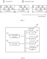
- FIG. 1 is a schematic diagram illustrating the resource allocation mechanism in the wireless device according to the present disclosure.
- a SA message which is indicated by a block in dots, is transmitted, and associated data, which is indicated by a block in slash, is transmitted accordingly.
- the SA message is used for indicating initiation of SPS like transmission.
- middle SA periods such as the second SA period, there is no SA message transmitted.
- a SA message is transmitted to indicate the termination of the SPS like transmission.
- the SA message transmitted in the first SA period is used to indicate data transmission resource in each of the multiple SA periods.
- FIG. 1 shows a first example of the resource allocation mechanism, in which a SA message is transmitted in the first SA period to indicate the start of the SPS like transmission, another SA message is transmitted in the last SA period to indicate the termination of the SPS like transmission, and no SA messages are transmitted in the middle SA periods.
- a SA message is transmitted in the first SA period to indicate information related to the SPS like transmission, such as the time period or the like, and no SA messages are transmitted in the SA periods other than the first SA period.
- the SA message transmitted in the first SA period is further used to indicate data transmission resource in each of the multiple SA periods.
- a wireless device which is applied in a wireless communication network comprising multiple wireless devices capable of communicating with each other directly, such as in the V2X communication network or the like.
- the wireless device 200 can comprise a processing circuitry 210 operative to multiplex data with a scheduling assignment message, into transmission information; and a transmitter 220 operative to transmit the transmission information in a scheduling assignment period, to another wireless device in the wireless communication network.
- the scheduling assignment message may be used for indicating data transmission resource in the scheduling assignment period.
- the scheduling assignment message may also be used for indicating data transmission resource in a previous scheduling assignment period. That means receiving wireless device needs to buffer the data and decode it after such device has successfully received scheduling assignment message in the next scheduling assignment period, which will be described in detail with reference to FIG. 3 .
- Respective components as described above do not limit the scope of the present disclosure.
- the functions of the above processing circuitry 210 and transmitter 220 may be implemented by hardware, and the above CPU 230, ROM 240, RAM 250 and/or storage unit 260 may not be necessary.
- the functions of the above processing circuitry 210 and transmitter 220 may also be implemented by functional software in combination with the above CPU 230, ROM 240, RAM 250 and/or storage unit 260 etc.
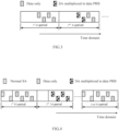
- FIG. 3 is a schematic diagram illustrating another resource allocation mechanism in a wireless device according to present disclosure.
- FIG. 3 there are multiple SA periods, similar to those in FIG. 1 .
- the difference between the present embodiment and the embodiment shown in FIG. 1 lies in that, there is a dedicated SA region in FIG. 1 for transmitting the SA message; while there may not be a dedicated SA region in the present embodiment as shown in FIG. 3 , in which all subframes in a scheduling assignment period can potentially transmit data.
- the difference between the present embodiment and the embodiment shown in FIG. 1 lies in that, in FIG. 3 , the SA message is multiplexed with the data into transmission information, which is indicated by blocks filled with dark squares.
- the transmission information is transmitted in a SA period, for example, the second SA period as shown in FIG.3 , to another wireless device.
- the SA message is used for indicating data transmission resource in the present SA period, when the current data transmission resource (e.g., subframe) is allowed to transmit the transmission information.
- the current data transmission resource e.g., subframe
- data when the current subframe is not allowed to transmit the transmission information, data may be transmitted first, for example, in a previous SA period such as the first SA period in FIG. 3 , and then the multiplexed SA message is transmitted, for example, in a following SA period such as the second SA period in FIG. 3 .
- the SA message is used for indicating data transmission resource in the previous SA period.
- some subframes may be buffered, and the data may be decoded after the multiplexed SA message is detected. The start of the data may be indicated by the multiplexed SA message.
- the wireless device may transmit data quickly and the latency may be reduced.
- FIG. 4 is a schematic diagram illustrating a further scheduling assignment mechanism according to an embodiment of the present disclosure.
- the scheduling assignment mechanism in FIG. 4 also adopts the SPS like mechanism, as described with reference to FIG. 1 .
- the difference between the present embodiment and the embodiment shown in FIG. 1 lies in that, there is no SA message transmitted in middle SA periods in FIG. 1 ; while the SA message multiplexed with the data is transmitted in the middle SA periods in the present embodiment.
- the transmission information is transmitted in the middle SA periods as shown in FIG. 4 , in another example not shown, it may be transmitted in both the middle SA periods and the last SA period.
- the SA message is multiplexed with data into transmission information as shown, and the transmission information is transmitted in the data transmission resource of at least one SA period other than the first SA period.
- Each of the multiple SA periods comprises a data region.
- the data transmission resource in each data region is indicated by the SA message.
- the SA message may be multiplexed with the data in various ways.
- the processing circuitry may embed the resource elements of SA message into the data resource in a physical layer, to form the transmission information, in which relevant resource elements of data resource is punctured.
- the processing circuitry may map the SA message into a part of the data transmission resource, such as one slot of a subframe, and map the data into the other part of the data transmission resource, such as the other slot of the subframe, to form the transmission information, in which a coding rate of the data is matched within the other part, such as the other slot, transmitting the data.
- the first SA period comprises a SA region in which another SA message for indicating the data transmission resource is transmitted.
- a field or a combination of several fields may be added into said another SA message to indicate parameters related to the SPS like transmission, for example, to indicate the start of the SPS like transmission, the time period of the SPS like transmission, the time/frequency resource of SPS or the like.
- a different RNTI Radio Network Temporary Identity
- the format of the SA message multiplexed with the data in the data region which may be referred to as the multiplexed SA message hereinafter
- the format of the multiplexed SA message may be the same as that of said another SA message transmitted in the first SA period, which may be referred to as the normal SA message hereinafter.
- the Sidelink Control Information (SCI) format 0 may be reused.
- the format of the multiplexed SA message may be more simplified as compared to that of the normal SA message. For example, a resource allocation field in the normal SA message may be removed or reduced in size, since the position of the multiplexed SA message may reflect the position of the data.
- a timing advance field in the normal SA message may be removed, since the data and the multiplexed SA message are operated in the same data resource, that is, they use the same timing advance.
- the transmitter may be operative to transmit the transmission information using a downlink timing which is based on reception timing from another wireless device and has no timing advance, in both an eNode B scheduling transmission, like the mode 1 transmission in the D2D network, and a UE autonomous scheduling transmission, like the mode 2 transmission in the D2D network.
- a timing advance may be applied to the first SA period.
- a time resource pattern (T-RPT) field in the normal SA message may be removed or reduced in size, since the multiplexed SA message may reflect certain T-RPT index, as described later with reference to FIG. 5 .
- the SPS like transmission may be enabled or disabled by a wireless device, and may be indicated through a broadcast channel, such as PSBCH or the like.
- the wireless device may be the present wireless device or other wireless devices in the communication network, as long as it may function as a synchronizing source.
- transmission properties such as MCS (modulation and coding scheme) or the like, may be adapted.
- the data transmission resource may be selected by the wireless device once in the first SA period, when the transmission from the wireless device to the other wireless device is scheduled by the wireless device autonomously. That is, in a case of the UE autonomous scheduling transmission, the wireless device may transmit the normal SA message in the first SA period and the multiplexed SA message in the following SA periods, and the wireless device just selects resource (SA or data) once in the first SA period. The resource will be repeated in the following SA periods.
- the data transmission resource may be selected by a base station when the transmission from the wireless device to the other wireless device is scheduled by the base station. That is, in a case of the eNode B based scheduling transmission, similarly, the wireless device may transmit the normal SA message in the first SA period and the multiplexed SA message in the following SA periods. However, different from that in the above case, the resource selection will follow the eNode B's guidance.
- FIG. 5 is a diagram schematically showing a position of a multiplexed SA message in time domain according to an embodiment of the present disclosure.
- the time position of the multiplexed SA message may be limited to first few "1" subframes the second T-RPT bitmap indicates.
- the value of the bitmap is, for example, "11100100" which means subframes #1, #2, #3 and #6 in slash are available for transmission.
- Such bitmap is repeated to the end of the SA period and a truncated bitmap is used for the last few subframes, as shown in FIG. 5 .
- bitmap is common for all UEs so that the receiving wireless device and the transmitting wireless device know when to apply the first bitmap, the second bitmap, and so on.
- the value of the bitmap shown in FIG. 5 is only an example, and other values of the bitmap are also possible.
- the starting subframe to apply the T-RPT pattern is aligned between the multiplexed SA message and the data.
- the timing to apply T-RPT pattern is cell-specific or group-specific, the transmitting wireless device and the receiving wireless device have the same understanding on the time to transmit the multiplexed SA message.
- the transmitter may be operative to transmit the transmission information in part of subframes applying time resource pattern (T-PRT) in a SA period.
- T-PRT time resource pattern
- the part of subframes may be specified, predefined or configured depending on resource allocation mode (eNode B scheduled or UE autonomous selection).
- the receiver does not know the value of the bitmap in advance, so it will presume one value of bitmap (time resource pattern), for example "11100100", and attempt to detect the multiplexed SA message. In order to reduce the decoding complexity, it is possible to restrict part of the T-RPT patterns to transmit the multiplexed SA message.
- the multiplexed SA message may be transmitted in various ways. As an example, the multiplexed SA message may be transmitted in one PRB in a subframe. As another example, the multiplexed SA message may be transmitted repeatedly in all allocated PRBs in a subframe. As a further example, the same multiplexed SA message may be transmitted across several PRBs in a subframe.
- the frequency position to transmit the multiplexed SA message in a SA period may be also limited.
- FIG. 6 is a diagram schematically showing a position of a multiplexed SA message in frequency domain according to an embodiment of the present disclosure.
- the frequency position of the multiplexed SA message may be linked with the T-RPT pattern. For example, if the T-RPT pattern is "11100100", the first PRB (Physical Resource Block) is used for transmitting the multiplexed SA message. If the T-RPT pattern is "11000000", the third PRB is used for transmitting the multiplexed SA message. That is, different T-RPT pattern is linked with different frequency position of the multiplexed SA message. Therefore, the transmitter may be operative to transmit the transmission information in a PRB of the data transmission resource, an index of the PRB being associated with a T-RPT index of the data transmission resource.
- the receiving wireless device it may presume certain T-RPT pattern and attempt to detect the multiplexed SA message. If the multiplexed SA message is detected, the T-RPT pattern is also known accordingly. In FIG. 6 , a candidate 1 is linked with the T-RPT pattern 1 and a candidate 2 is linked with the T-RPT pattern 2.
- the frequency resource allocation should include corresponding linked PRB to transmit the multiplexed SA message. Therefore, in such example, the complexity of the receiving wireless device may be reduced, but there may be some restriction on resource allocation in frequency domain.
- the frequency position of the multiplexed SA message may be fixed regardless of the T-RPT pattern. That is, the transmitter may be operative to transmit the transmission information in a fixed PRB of the data transmission resource. For example, PRBs 1 and 13 may always be the possible candidates to transmit the multiplexed SA message. In such a case, the data resource should include one of the candidate PRBs.
- the multiplexed SA message is described in a SPS like resource allocation scenario in the present embodiment, the present disclosure is not limited thereto, and may be applied to a dynamic resource allocation or even in a scenario without a SA resource pool as shown in FIG. 3 .
- the SA channel used for transmitting one SA message or the data channel used for transmitting one transport block is repeated. Between or among the repeated SA channels or the repeated data channels, a certain hopping rule may be applied. For example, in FIG. 4 , the SA channel is repeated twice, the data channel is repeated four times, and the multiplexed SA message is transmitted in four repeated data channels. However, it is just an example, and the present disclosure is not limited thereto. Those skilled in the art shall understand that the SA channel and the data channel may be repeated other times than those shown in the figures, and the multiplexed SA message may be transmitted in any one or more of the repeated data channels.
- the resource allocation mechanisms may be applied to both the eNode B scheduled transmission, like the mode 1 transmission in the D2D network, and the UE autonomous transmission, like the mode 2 transmission in the D2D network.
- the SA resource pool may be relaxed, and the newly joined UE will not miss any data transmitted in any SA period other than the first SA period.
- FIG. 7 is a block diagram schematically illustrating a wireless device according to an embodiment of the present disclosure.
- the wireless device 700 can comprise a receiver 710 operative to receive transmission information in a scheduling assignment period, from another wireless device in the communication network; and a processing circuitry 720 operative to de-multiplex a scheduling assignment message from the transmission information, and to decode data from the transmission information based on the scheduling assignment message.
- the scheduling assignment message may be used for indicating data transmission resource in the scheduling assignment period. Alternatively, the scheduling assignment message may also be used for indicating data transmission resource in a previous scheduling assignment period.
- the wireless device 700 may optionally include a CPU (Central Processing Unit) 730 for executing related programs to process various data and control operations of respective units in the wireless device 700, a ROM (Read Only Memory) 740 for storing various programs required for performing various process and control by the CPU 730, a RAM (Random Access Memory) 750 for storing intermediate data temporarily produced in the procedure of process and control by the CPU 730, and/or a storage unit 760 for storing various programs, data and so on.
- the above receiver 710, processing circuitry 720, CPU 730, ROM 740, RAM 750 and/or storage unit 760 etc. may be interconnected via data and/or command bus 770 and transfer signals between one another.
- Respective components as described above do not limit the scope of the present disclosure.
- the functions of the above receiver 710 and processing circuitry 720 may be implemented by hardware, and the above CPU 730, ROM 740, RAM 750 and/or storage unit 760 may not be necessary.
- the functions of the above receiver 710, processing circuitry 720 may also be implemented by functional software in combination with the above CPU 730, ROM 740, RAM 750 and/or storage unit 760 etc.
- the data transmission resource is in a data region of a scheduling assignment period including a SA region and the data region.
- the processing circuitry may be operative to try to blindly decode the scheduling assignment message from the SA region first. Then the processing circuitry may be operative to blindly decode the SA message from the data region. After decoding the SA message, the data is decoded accordingly.
- the processing circuitry may be operative to decode the SA message from the SA region, when it is indicated that the SA message and the data are not multiplexed through a broadcast channel, such as the PSBCH or the like, or when it is indicated that the SPS like resource allocation is not enabled through the broadcast channel.
- a broadcast channel such as the PSBCH or the like
- another SA message (the normal SA message as described above) is transmitted in the first SA period.
- the wireless device which has already detected the normal SA message indicating the SPS like resource allocation in the first SA period, it may not require to detect or monitor the multiplexed SA message in the following SA periods, since it already knows the SPS like transmission from beginning based on the normal SA message in the SA resource pool.
- the wireless device newly joining in the following SA periods it will firstly detect the normal SA message in the SA resource pool, and then detect the multiplexed SA message in the data resource pool as described above.
- the new joined wireless device can still decode data of the SPS like transmission correctly.
- FIG. 8 is a flowchart illustrating a wireless communication method 800 according to an embodiment of the present disclosure.
- data is multiplexed with a scheduling assignment message, into transmission information.
- the transmission information is transmitted in a scheduling assignment period, to another wireless device in the communication network.
- the scheduling assignment message may be used for indicating data transmission resource in the scheduling assignment period or in a previous scheduling assignment period.
- FIG. 9 is a flowchart illustrating another wireless communication method 900 according to an embodiment of the present disclosure.
- transmission information is received in a scheduling assignment period, from another wireless device in the communication network.
- a scheduling assignment message is de-multiplexed from the transmission information, and data is decoded from the transmission information based on the scheduling assignment message, at a block 930.
- the newly joined UE will not miss any data transmitted in any SA period other than the first SA period.
- the present disclosure can be realized by software, hardware, or software in cooperation with hardware.
- Each functional block used in the description of each embodiment described above can be realized by an LSI as an integrated circuit, and each process described in the each embodiment may be controlled by LSI. They may be individually formed as chips, or one chip may be formed so as to include a part or all of the functional blocks. They may include a data input and output coupled thereto.
- the LSI here may be referred to as an IC, a system LSI, a super LSI, or an ultra LSI depending on a difference in the degree of integration.
- the technique of implementing an integrated circuit is not limited to the LSI and may be realized by using a dedicated circuit or a general-purpose processor.
- a FPGA Field Programmable Gate Array
- a reconfigurable processor in which the connections and the settings of circuits cells disposed inside the LSI can be reconfigured may be used.
Landscapes
- Engineering & Computer Science (AREA)
- Signal Processing (AREA)
- Computer Networks & Wireless Communication (AREA)
- Mobile Radio Communication Systems (AREA)
- Time-Division Multiplex Systems (AREA)
Priority Applications (2)
| Application Number | Priority Date | Filing Date | Title |
|---|---|---|---|
| EP23181245.4A EP4255077B1 (en) | 2015-11-05 | 2015-11-05 | Wireless device and wireless communication method |
| EP20170380.8A EP3709745B1 (en) | 2015-11-05 | 2015-11-05 | Wireless device and wireless communication method |
Applications Claiming Priority (3)
| Application Number | Priority Date | Filing Date | Title |
|---|---|---|---|
| EP15907625.6A EP3372027B1 (en) | 2015-11-05 | 2015-11-05 | Wireless device and wireless communication method |
| PCT/CN2015/093894 WO2017075783A1 (en) | 2015-11-05 | 2015-11-05 | Wireless device and wireless communication method |
| EP20170380.8A EP3709745B1 (en) | 2015-11-05 | 2015-11-05 | Wireless device and wireless communication method |
Related Parent Applications (2)
| Application Number | Title | Priority Date | Filing Date |
|---|---|---|---|
| EP15907625.6A Division EP3372027B1 (en) | 2015-11-05 | 2015-11-05 | Wireless device and wireless communication method |
| EP15907625.6A Division-Into EP3372027B1 (en) | 2015-11-05 | 2015-11-05 | Wireless device and wireless communication method |
Related Child Applications (2)
| Application Number | Title | Priority Date | Filing Date |
|---|---|---|---|
| EP23181245.4A Division EP4255077B1 (en) | 2015-11-05 | 2015-11-05 | Wireless device and wireless communication method |
| EP23181245.4A Division-Into EP4255077B1 (en) | 2015-11-05 | 2015-11-05 | Wireless device and wireless communication method |
Publications (2)
| Publication Number | Publication Date |
|---|---|
| EP3709745A1 EP3709745A1 (en) | 2020-09-16 |
| EP3709745B1 true EP3709745B1 (en) | 2023-08-09 |
Family
ID=58661489
Family Applications (3)
| Application Number | Title | Priority Date | Filing Date |
|---|---|---|---|
| EP20170380.8A Active EP3709745B1 (en) | 2015-11-05 | 2015-11-05 | Wireless device and wireless communication method |
| EP23181245.4A Active EP4255077B1 (en) | 2015-11-05 | 2015-11-05 | Wireless device and wireless communication method |
| EP15907625.6A Active EP3372027B1 (en) | 2015-11-05 | 2015-11-05 | Wireless device and wireless communication method |
Family Applications After (2)
| Application Number | Title | Priority Date | Filing Date |
|---|---|---|---|
| EP23181245.4A Active EP4255077B1 (en) | 2015-11-05 | 2015-11-05 | Wireless device and wireless communication method |
| EP15907625.6A Active EP3372027B1 (en) | 2015-11-05 | 2015-11-05 | Wireless device and wireless communication method |
Country Status (10)
Families Citing this family (12)
| Publication number | Priority date | Publication date | Assignee | Title |
|---|---|---|---|---|
| EP3709745B1 (en) | 2015-11-05 | 2023-08-09 | Panasonic Intellectual Property Corporation of America | Wireless device and wireless communication method |
| WO2017128757A1 (zh) * | 2016-01-27 | 2017-08-03 | 华为技术有限公司 | 一种通信方法及通信装置 |
| US10716130B2 (en) | 2016-02-05 | 2020-07-14 | Guangdong Oppo Mobile Telecommunications Corp., Ltd. | Communication method, terminal equipment, and network equipment |
| WO2017150959A1 (ko) | 2016-03-04 | 2017-09-08 | 엘지전자 주식회사 | 무선 통신 시스템에서 단말에 의해 수행되는 v2x 전송 자원 선택 방법 및 상기 방법을 이용하는 단말 |
| US11147044B2 (en) | 2016-03-04 | 2021-10-12 | Lg Electronics Inc. | V2X transmission resource selecting method implemented by terminal in wireless communication system and terminal using same |
| JP2019525648A (ja) * | 2016-08-11 | 2019-09-05 | 華為技術有限公司Huawei Technologies Co.,Ltd. | スケジューリング割当情報送信方法及びシステム並びに装置 |
| EP3685613B1 (en) * | 2017-09-18 | 2022-07-13 | Telefonaktiebolaget LM Ericsson (Publ) | A method and network node for radio resource allocation |
| CN110738715B (zh) * | 2018-07-19 | 2021-07-09 | 北京大学 | 一种基于样例的动态文本特效的自动迁移方法 |
| CN110062465B (zh) * | 2018-09-29 | 2021-05-14 | 中国信息通信研究院 | 一种终端直通通信的资源分配方法 |
| JP7531597B2 (ja) | 2020-02-14 | 2024-08-09 | オッポ広東移動通信有限公司 | 情報処理方法、装置、記憶媒体、プロセッサ、及び電子デバイス |
| EP4158969A4 (en) * | 2020-05-29 | 2024-02-28 | Qualcomm Incorporated | MULTIPLEXING SIDELINK SYNCHRONIZATION SIGNAL BLOCK (S-SSB) AND SIDELINK PHYSICAL CONTROL CHANNEL (PSCCH/PSCCH) AND OCCUPANCY CHANNEL BANDWIDTH (OCB) FULFILLMENT FOR NEW RADIO-UNLICENSED (NR-U) |
| KR20250071554A (ko) * | 2023-11-15 | 2025-05-22 | 현대모비스 주식회사 | 사이드링크를 통한 ta 정보 공유 방법 및 이를 위한 장치 |
Family Cites Families (40)
| Publication number | Priority date | Publication date | Assignee | Title |
|---|---|---|---|---|
| CN101617559A (zh) * | 2007-01-09 | 2009-12-30 | 株式会社Ntt都科摩 | 基站、通信终端、发送方法及接收方法 |
| US8798084B2 (en) * | 2007-04-13 | 2014-08-05 | Hart Communication Foundation | Increasing reliability and reducing latency in a wireless network |
| EP2166804A1 (en) | 2008-09-17 | 2010-03-24 | Panasonic Corporation | Deactivation of semi-persistent resource allocations in a mobile communication network |
| US8433251B2 (en) * | 2009-09-28 | 2013-04-30 | Qualcomm Incorporated | Control information signaling |
| CN104320225A (zh) * | 2010-01-07 | 2015-01-28 | 三星电子株式会社 | 发送/接收自动重复请求确认的用户设备/基站及方法 |
| CN103098537B (zh) * | 2010-09-14 | 2016-05-25 | 诺基亚技术有限公司 | 一种无线通信方法和装置 |
| EP3525385B1 (en) * | 2011-10-03 | 2020-07-01 | Telefonaktiebolaget LM Ericsson (publ) | Multiplexing control and data in one resource block |
| CN103298113B (zh) * | 2012-02-23 | 2016-08-10 | 华为技术有限公司 | 端到端d2d通信方法和d2d通信设备 |
| US9538502B2 (en) * | 2012-05-01 | 2017-01-03 | Qualcomm Incorporated | Methods and apparatus for managing control and data transmissions for low cost user equipments |
| US9949265B2 (en) * | 2012-05-04 | 2018-04-17 | Comcast Cable Communications, Llc | Control channel in a wireless communication system |
| CN105474726B (zh) * | 2013-08-07 | 2019-05-31 | 三星电子株式会社 | 用于在无线通信系统中传送和接收资源分配信息的方法和装置 |
| CN104469961A (zh) * | 2013-09-25 | 2015-03-25 | 中兴通讯股份有限公司 | 一种设备到设备的通信方法、设备和系统 |
| KR102193118B1 (ko) * | 2013-11-08 | 2020-12-18 | 삼성전자주식회사 | 기기 대 기기 통신을 위한 제어 정보 전송 방법 및 장치 |
| WO2015111909A1 (ko) * | 2014-01-21 | 2015-07-30 | 엘지전자(주) | 단말 간 통신을 지원하는 무선 통신 시스템에서 단말 식별자를 결정하기 위한 방법 및 이를 위한 장치 |
| WO2015115793A1 (ko) | 2014-01-28 | 2015-08-06 | 엘지전자 주식회사 | 무선 통신 시스템에서 장치 대 장치 단말의 신호 송수신 방법 및 장치 |
| CN104811892B (zh) | 2014-01-29 | 2020-03-13 | 中兴通讯股份有限公司 | 一种资源分配方法、装置及系统 |
| US20160345312A1 (en) * | 2014-02-11 | 2016-11-24 | Lg Electronics Inc. | Method and apparatus for transmitting and receiving signals in wireless communication system |
| US20160360541A1 (en) | 2014-02-12 | 2016-12-08 | Lg Electronics Inc. | Method for transmitting/receiving signal in wireless communication system, and apparatus therefor |
| US20150245334A1 (en) | 2014-02-27 | 2015-08-27 | Innovative Sonic Corporation | Method and apparatus for device to device service in a wireless communication system |
| CN110234168B (zh) * | 2014-02-27 | 2022-12-06 | Lg 电子株式会社 | 在无线通信系统中发送侧链路数据信号的方法和装置 |
| US10524282B2 (en) * | 2014-03-19 | 2019-12-31 | Qualcomm Incorporated | Scheduling assignment content and transmission in wireless communications |
| JP6189238B2 (ja) | 2014-03-20 | 2017-08-30 | 株式会社Nttドコモ | ユーザ装置、及び信号送受信方法 |
| US10660146B2 (en) | 2014-03-21 | 2020-05-19 | Samsung Electronics Co., Ltd. | Methods and apparatus for device to device synchronization priority |
| WO2015147608A1 (ko) * | 2014-03-28 | 2015-10-01 | 엘지전자 주식회사 | 단말 간 통신을 지원하는 무선 통신 시스템에서 신호를 송수신하는 방법 및 이를 위한 장치 |
| KR101793118B1 (ko) | 2014-03-30 | 2017-11-02 | 엘지전자 주식회사 | 무선 통신 시스템에서 신호를 송수신하기 위한 방법 및 이를 위한 장치 |
| JP2017516361A (ja) | 2014-03-30 | 2017-06-15 | エルジー エレクトロニクス インコーポレイティド | 端末間通信を支援する無線通信システムにおけるダウンリンク制御情報の送受信方法及びそのための装置 |
| EP3128782B1 (en) * | 2014-04-02 | 2019-10-23 | LG Electronics Inc. | Method for transceiving signal in wireless communication system and apparatus therefor |
| WO2015179826A1 (en) * | 2014-05-22 | 2015-11-26 | Kyocera Corporation | Physical channel structure for communication in unlicensed frequency band |
| EP3157294B1 (en) | 2014-06-10 | 2019-08-07 | LG Electronics Inc. | Method for controlling timing advance for direct communication between terminals in wireless communication system, and apparatus therefor |
| CN105338633A (zh) * | 2014-07-08 | 2016-02-17 | 夏普株式会社 | 基站、用户设备及相关方法 |
| MY193658A (en) | 2014-08-06 | 2022-10-23 | Interdigital Patent Holdings Inc | Device-to-device (d2d) pre-emption and access control |
| JP6405447B2 (ja) * | 2014-08-08 | 2018-10-17 | 京セラ株式会社 | ネットワーク支援参照信号送信を有する装置間(d2d)チャネル管理 |
| US9794976B2 (en) | 2014-09-03 | 2017-10-17 | Futurewei Technologies, Inc. | System and method for D2D resource allocation |
| WO2016085210A1 (ko) * | 2014-11-25 | 2016-06-02 | 엘지전자(주) | 단말 간 통신을 지원하는 무선 통신 시스템에서 단말 간 통신을 조력하기 위한 방법 및 이를 위한 장치 |
| US20160249344A1 (en) * | 2015-02-23 | 2016-08-25 | Rohde & Schwarz Gmbh & Co. Kg | Method and Apparatus for Providing a Degree of a Resource Pool Occupation of Resources Used in Device-to-Device Communication |
| US20160295624A1 (en) | 2015-04-02 | 2016-10-06 | Samsung Electronics Co., Ltd | Methods and apparatus for resource pool design for vehicular communications |
| WO2016182294A1 (ko) | 2015-05-08 | 2016-11-17 | 엘지전자 주식회사 | 무선 통신 시스템에서 장치 대 장치 통신 단말의 디스커버리 신호 송수신 방법 및 장치 |
| US10064212B2 (en) * | 2015-05-14 | 2018-08-28 | Blackberry Limited | Transmitting a scheduling request for a device-to-device transmission |
| CN107926005B (zh) * | 2015-08-13 | 2022-03-18 | 株式会社Ntt都科摩 | 用户装置及信号发送方法 |
| EP3709745B1 (en) | 2015-11-05 | 2023-08-09 | Panasonic Intellectual Property Corporation of America | Wireless device and wireless communication method |
-
2015
- 2015-11-05 EP EP20170380.8A patent/EP3709745B1/en active Active
- 2015-11-05 AU AU2015414016A patent/AU2015414016B2/en active Active
- 2015-11-05 WO PCT/CN2015/093894 patent/WO2017075783A1/en active Application Filing
- 2015-11-05 EP EP23181245.4A patent/EP4255077B1/en active Active
- 2015-11-05 US US15/768,481 patent/US10932280B2/en active Active
- 2015-11-05 BR BR112018005697-9A patent/BR112018005697B1/pt active IP Right Grant
- 2015-11-05 RU RU2018114263A patent/RU2699069C1/ru active
- 2015-11-05 CN CN201580083984.7A patent/CN108353386B/zh active Active
- 2015-11-05 KR KR1020227040093A patent/KR102509160B1/ko active Active
- 2015-11-05 EP EP15907625.6A patent/EP3372027B1/en active Active
- 2015-11-05 KR KR1020187009093A patent/KR102469097B1/ko active Active
- 2015-11-05 MX MX2018003933A patent/MX382993B/es unknown
- 2015-11-05 CN CN202310376306.6A patent/CN116506962A/zh active Pending
- 2015-11-05 JP JP2018517396A patent/JP6865215B6/ja active Active
-
2021
- 2021-01-19 US US17/152,468 patent/US11523405B2/en active Active
-
2022
- 2022-10-11 US US17/963,930 patent/US11812424B2/en active Active
-
2023
- 2023-10-03 US US18/480,421 patent/US12213125B2/en active Active
-
2024
- 2024-12-19 US US18/987,665 patent/US20250126611A1/en active Pending
Also Published As
Similar Documents
| Publication | Publication Date | Title |
|---|---|---|
| US11812424B2 (en) | Wireless device and wireless communication method for scheduling assignment message transmission | |
| US12342371B2 (en) | User equipment and wireless communication method | |
| AU2018430965B2 (en) | Control information transmission method and apparatus, resource pool configuration method and apparatus, and communication device | |
| JP7203948B2 (ja) | 通信装置、通信方法、及び集積回路 | |
| JP2023025241A (ja) | 通信装置、通信方法、及び集積回路 | |
| KR20160129053A (ko) | 신호 재송신 장치 및 방법 및 통신 시스템 | |
| CN107006003A (zh) | 在多个时间实例中的上行链路资源调度 | |
| WO2018171352A1 (zh) | 一种数据传输方法及终端 | |
| JP6923698B2 (ja) | 無線通信装置、無線通信方法および集積回路 |
Legal Events
| Date | Code | Title | Description |
|---|---|---|---|
| PUAI | Public reference made under article 153(3) epc to a published international application that has entered the european phase |
Free format text: ORIGINAL CODE: 0009012 |
|
| STAA | Information on the status of an ep patent application or granted ep patent |
Free format text: STATUS: REQUEST FOR EXAMINATION WAS MADE |
|
| 17P | Request for examination filed |
Effective date: 20200420 |
|
| AC | Divisional application: reference to earlier application |
Ref document number: 3372027 Country of ref document: EP Kind code of ref document: P |
|
| AK | Designated contracting states |
Kind code of ref document: A1 Designated state(s): AL AT BE BG CH CY CZ DE DK EE ES FI FR GB GR HR HU IE IS IT LI LT LU LV MC MK MT NL NO PL PT RO RS SE SI SK SM TR |
|
| STAA | Information on the status of an ep patent application or granted ep patent |
Free format text: STATUS: EXAMINATION IS IN PROGRESS |
|
| 17Q | First examination report despatched |
Effective date: 20220210 |
|
| REG | Reference to a national code |
Ref country code: DE Ref legal event code: R079 Ref document number: 602015085111 Country of ref document: DE Free format text: PREVIOUS MAIN CLASS: H04W0072120000 Ipc: H04W0072200000 Ref country code: DE Ref legal event code: R079 Free format text: PREVIOUS MAIN CLASS: H04W0072120000 Ipc: H04W0072200000 |
|
| GRAP | Despatch of communication of intention to grant a patent |
Free format text: ORIGINAL CODE: EPIDOSNIGR1 |
|
| STAA | Information on the status of an ep patent application or granted ep patent |
Free format text: STATUS: GRANT OF PATENT IS INTENDED |
|
| RIC1 | Information provided on ipc code assigned before grant |
Ipc: H04W 72/20 20230101AFI20230124BHEP |
|
| INTG | Intention to grant announced |
Effective date: 20230223 |
|
| GRAS | Grant fee paid |
Free format text: ORIGINAL CODE: EPIDOSNIGR3 |
|
| GRAA | (expected) grant |
Free format text: ORIGINAL CODE: 0009210 |
|
| STAA | Information on the status of an ep patent application or granted ep patent |
Free format text: STATUS: THE PATENT HAS BEEN GRANTED |
|
| AC | Divisional application: reference to earlier application |
Ref document number: 3372027 Country of ref document: EP Kind code of ref document: P |
|
| AK | Designated contracting states |
Kind code of ref document: B1 Designated state(s): AL AT BE BG CH CY CZ DE DK EE ES FI FR GB GR HR HU IE IS IT LI LT LU LV MC MK MT NL NO PL PT RO RS SE SI SK SM TR |
|
| REG | Reference to a national code |
Ref country code: GB Ref legal event code: FG4D |
|
| REG | Reference to a national code |
Ref country code: CH Ref legal event code: EP |
|
| REG | Reference to a national code |
Ref country code: DE Ref legal event code: R096 Ref document number: 602015085111 Country of ref document: DE |
|
| REG | Reference to a national code |
Ref country code: IE Ref legal event code: FG4D |
|
| REG | Reference to a national code |
Ref country code: LT Ref legal event code: MG9D |
|
| REG | Reference to a national code |
Ref country code: NL Ref legal event code: MP Effective date: 20230809 |
|
| REG | Reference to a national code |
Ref country code: AT Ref legal event code: MK05 Ref document number: 1598982 Country of ref document: AT Kind code of ref document: T Effective date: 20230809 |
|
| PG25 | Lapsed in a contracting state [announced via postgrant information from national office to epo] |
Ref country code: GR Free format text: LAPSE BECAUSE OF FAILURE TO SUBMIT A TRANSLATION OF THE DESCRIPTION OR TO PAY THE FEE WITHIN THE PRESCRIBED TIME-LIMIT Effective date: 20231110 |
|
| PG25 | Lapsed in a contracting state [announced via postgrant information from national office to epo] |
Ref country code: IS Free format text: LAPSE BECAUSE OF FAILURE TO SUBMIT A TRANSLATION OF THE DESCRIPTION OR TO PAY THE FEE WITHIN THE PRESCRIBED TIME-LIMIT Effective date: 20231209 |
|
| PG25 | Lapsed in a contracting state [announced via postgrant information from national office to epo] |
Ref country code: SE Free format text: LAPSE BECAUSE OF FAILURE TO SUBMIT A TRANSLATION OF THE DESCRIPTION OR TO PAY THE FEE WITHIN THE PRESCRIBED TIME-LIMIT Effective date: 20230809 Ref country code: RS Free format text: LAPSE BECAUSE OF FAILURE TO SUBMIT A TRANSLATION OF THE DESCRIPTION OR TO PAY THE FEE WITHIN THE PRESCRIBED TIME-LIMIT Effective date: 20230809 Ref country code: PT Free format text: LAPSE BECAUSE OF FAILURE TO SUBMIT A TRANSLATION OF THE DESCRIPTION OR TO PAY THE FEE WITHIN THE PRESCRIBED TIME-LIMIT Effective date: 20231211 Ref country code: NO Free format text: LAPSE BECAUSE OF FAILURE TO SUBMIT A TRANSLATION OF THE DESCRIPTION OR TO PAY THE FEE WITHIN THE PRESCRIBED TIME-LIMIT Effective date: 20231109 Ref country code: NL Free format text: LAPSE BECAUSE OF FAILURE TO SUBMIT A TRANSLATION OF THE DESCRIPTION OR TO PAY THE FEE WITHIN THE PRESCRIBED TIME-LIMIT Effective date: 20230809 Ref country code: LV Free format text: LAPSE BECAUSE OF FAILURE TO SUBMIT A TRANSLATION OF THE DESCRIPTION OR TO PAY THE FEE WITHIN THE PRESCRIBED TIME-LIMIT Effective date: 20230809 Ref country code: LT Free format text: LAPSE BECAUSE OF FAILURE TO SUBMIT A TRANSLATION OF THE DESCRIPTION OR TO PAY THE FEE WITHIN THE PRESCRIBED TIME-LIMIT Effective date: 20230809 Ref country code: IS Free format text: LAPSE BECAUSE OF FAILURE TO SUBMIT A TRANSLATION OF THE DESCRIPTION OR TO PAY THE FEE WITHIN THE PRESCRIBED TIME-LIMIT Effective date: 20231209 Ref country code: HR Free format text: LAPSE BECAUSE OF FAILURE TO SUBMIT A TRANSLATION OF THE DESCRIPTION OR TO PAY THE FEE WITHIN THE PRESCRIBED TIME-LIMIT Effective date: 20230809 Ref country code: GR Free format text: LAPSE BECAUSE OF FAILURE TO SUBMIT A TRANSLATION OF THE DESCRIPTION OR TO PAY THE FEE WITHIN THE PRESCRIBED TIME-LIMIT Effective date: 20231110 Ref country code: FI Free format text: LAPSE BECAUSE OF FAILURE TO SUBMIT A TRANSLATION OF THE DESCRIPTION OR TO PAY THE FEE WITHIN THE PRESCRIBED TIME-LIMIT Effective date: 20230809 Ref country code: AT Free format text: LAPSE BECAUSE OF FAILURE TO SUBMIT A TRANSLATION OF THE DESCRIPTION OR TO PAY THE FEE WITHIN THE PRESCRIBED TIME-LIMIT Effective date: 20230809 |
|
| PG25 | Lapsed in a contracting state [announced via postgrant information from national office to epo] |
Ref country code: PL Free format text: LAPSE BECAUSE OF FAILURE TO SUBMIT A TRANSLATION OF THE DESCRIPTION OR TO PAY THE FEE WITHIN THE PRESCRIBED TIME-LIMIT Effective date: 20230809 |
|
| PG25 | Lapsed in a contracting state [announced via postgrant information from national office to epo] |
Ref country code: ES Free format text: LAPSE BECAUSE OF FAILURE TO SUBMIT A TRANSLATION OF THE DESCRIPTION OR TO PAY THE FEE WITHIN THE PRESCRIBED TIME-LIMIT Effective date: 20230809 |
|
| PG25 | Lapsed in a contracting state [announced via postgrant information from national office to epo] |
Ref country code: SM Free format text: LAPSE BECAUSE OF FAILURE TO SUBMIT A TRANSLATION OF THE DESCRIPTION OR TO PAY THE FEE WITHIN THE PRESCRIBED TIME-LIMIT Effective date: 20230809 Ref country code: RO Free format text: LAPSE BECAUSE OF FAILURE TO SUBMIT A TRANSLATION OF THE DESCRIPTION OR TO PAY THE FEE WITHIN THE PRESCRIBED TIME-LIMIT Effective date: 20230809 Ref country code: ES Free format text: LAPSE BECAUSE OF FAILURE TO SUBMIT A TRANSLATION OF THE DESCRIPTION OR TO PAY THE FEE WITHIN THE PRESCRIBED TIME-LIMIT Effective date: 20230809 Ref country code: EE Free format text: LAPSE BECAUSE OF FAILURE TO SUBMIT A TRANSLATION OF THE DESCRIPTION OR TO PAY THE FEE WITHIN THE PRESCRIBED TIME-LIMIT Effective date: 20230809 Ref country code: DK Free format text: LAPSE BECAUSE OF FAILURE TO SUBMIT A TRANSLATION OF THE DESCRIPTION OR TO PAY THE FEE WITHIN THE PRESCRIBED TIME-LIMIT Effective date: 20230809 Ref country code: CZ Free format text: LAPSE BECAUSE OF FAILURE TO SUBMIT A TRANSLATION OF THE DESCRIPTION OR TO PAY THE FEE WITHIN THE PRESCRIBED TIME-LIMIT Effective date: 20230809 Ref country code: SK Free format text: LAPSE BECAUSE OF FAILURE TO SUBMIT A TRANSLATION OF THE DESCRIPTION OR TO PAY THE FEE WITHIN THE PRESCRIBED TIME-LIMIT Effective date: 20230809 |
|
| REG | Reference to a national code |
Ref country code: DE Ref legal event code: R097 Ref document number: 602015085111 Country of ref document: DE |
|
| PG25 | Lapsed in a contracting state [announced via postgrant information from national office to epo] |
Ref country code: IT Free format text: LAPSE BECAUSE OF FAILURE TO SUBMIT A TRANSLATION OF THE DESCRIPTION OR TO PAY THE FEE WITHIN THE PRESCRIBED TIME-LIMIT Effective date: 20230809 |
|
| PLBE | No opposition filed within time limit |
Free format text: ORIGINAL CODE: 0009261 |
|
| STAA | Information on the status of an ep patent application or granted ep patent |
Free format text: STATUS: NO OPPOSITION FILED WITHIN TIME LIMIT |
|
| REG | Reference to a national code |
Ref country code: CH Ref legal event code: PL |
|
| PG25 | Lapsed in a contracting state [announced via postgrant information from national office to epo] |
Ref country code: MC Free format text: LAPSE BECAUSE OF FAILURE TO SUBMIT A TRANSLATION OF THE DESCRIPTION OR TO PAY THE FEE WITHIN THE PRESCRIBED TIME-LIMIT Effective date: 20230809 |
|
| PG25 | Lapsed in a contracting state [announced via postgrant information from national office to epo] |
Ref country code: LU Free format text: LAPSE BECAUSE OF NON-PAYMENT OF DUE FEES Effective date: 20231105 |
|
| 26N | No opposition filed |
Effective date: 20240513 |
|
| PG25 | Lapsed in a contracting state [announced via postgrant information from national office to epo] |
Ref country code: CH Free format text: LAPSE BECAUSE OF NON-PAYMENT OF DUE FEES Effective date: 20231130 |
|
| GBPC | Gb: european patent ceased through non-payment of renewal fee |
Effective date: 20231109 |
|
| PG25 | Lapsed in a contracting state [announced via postgrant information from national office to epo] |
Ref country code: MC Free format text: LAPSE BECAUSE OF FAILURE TO SUBMIT A TRANSLATION OF THE DESCRIPTION OR TO PAY THE FEE WITHIN THE PRESCRIBED TIME-LIMIT Effective date: 20230809 Ref country code: LU Free format text: LAPSE BECAUSE OF NON-PAYMENT OF DUE FEES Effective date: 20231105 Ref country code: CH Free format text: LAPSE BECAUSE OF NON-PAYMENT OF DUE FEES Effective date: 20231130 Ref country code: SI Free format text: LAPSE BECAUSE OF FAILURE TO SUBMIT A TRANSLATION OF THE DESCRIPTION OR TO PAY THE FEE WITHIN THE PRESCRIBED TIME-LIMIT Effective date: 20230809 |
|
| REG | Reference to a national code |
Ref country code: BE Ref legal event code: MM Effective date: 20231130 |
|
| REG | Reference to a national code |
Ref country code: IE Ref legal event code: MM4A |
|
| PG25 | Lapsed in a contracting state [announced via postgrant information from national office to epo] |
Ref country code: IE Free format text: LAPSE BECAUSE OF NON-PAYMENT OF DUE FEES Effective date: 20231105 |
|
| PG25 | Lapsed in a contracting state [announced via postgrant information from national office to epo] |
Ref country code: GB Free format text: LAPSE BECAUSE OF NON-PAYMENT OF DUE FEES Effective date: 20231109 |
|
| PG25 | Lapsed in a contracting state [announced via postgrant information from national office to epo] |
Ref country code: BE Free format text: LAPSE BECAUSE OF NON-PAYMENT OF DUE FEES Effective date: 20231130 |
|
| PG25 | Lapsed in a contracting state [announced via postgrant information from national office to epo] |
Ref country code: FR Free format text: LAPSE BECAUSE OF NON-PAYMENT OF DUE FEES Effective date: 20231130 |
|
| PG25 | Lapsed in a contracting state [announced via postgrant information from national office to epo] |
Ref country code: IE Free format text: LAPSE BECAUSE OF NON-PAYMENT OF DUE FEES Effective date: 20231105 Ref country code: GB Free format text: LAPSE BECAUSE OF NON-PAYMENT OF DUE FEES Effective date: 20231109 Ref country code: FR Free format text: LAPSE BECAUSE OF NON-PAYMENT OF DUE FEES Effective date: 20231130 Ref country code: BE Free format text: LAPSE BECAUSE OF NON-PAYMENT OF DUE FEES Effective date: 20231130 |
|
| PG25 | Lapsed in a contracting state [announced via postgrant information from national office to epo] |
Ref country code: BG Free format text: LAPSE BECAUSE OF FAILURE TO SUBMIT A TRANSLATION OF THE DESCRIPTION OR TO PAY THE FEE WITHIN THE PRESCRIBED TIME-LIMIT Effective date: 20230809 |
|
| PG25 | Lapsed in a contracting state [announced via postgrant information from national office to epo] |
Ref country code: BG Free format text: LAPSE BECAUSE OF FAILURE TO SUBMIT A TRANSLATION OF THE DESCRIPTION OR TO PAY THE FEE WITHIN THE PRESCRIBED TIME-LIMIT Effective date: 20230809 |
|
| PGFP | Annual fee paid to national office [announced via postgrant information from national office to epo] |
Ref country code: DE Payment date: 20241121 Year of fee payment: 10 |
|
| PG25 | Lapsed in a contracting state [announced via postgrant information from national office to epo] |
Ref country code: CY Free format text: LAPSE BECAUSE OF FAILURE TO SUBMIT A TRANSLATION OF THE DESCRIPTION OR TO PAY THE FEE WITHIN THE PRESCRIBED TIME-LIMIT; INVALID AB INITIO Effective date: 20151105 |
|
| PG25 | Lapsed in a contracting state [announced via postgrant information from national office to epo] |
Ref country code: HU Free format text: LAPSE BECAUSE OF FAILURE TO SUBMIT A TRANSLATION OF THE DESCRIPTION OR TO PAY THE FEE WITHIN THE PRESCRIBED TIME-LIMIT; INVALID AB INITIO Effective date: 20151105 |