EP3709732A1 - Period information indication method for common control resource set of remaining key system information - Google Patents
Period information indication method for common control resource set of remaining key system information Download PDFInfo
- Publication number
- EP3709732A1 EP3709732A1 EP17932403.3A EP17932403A EP3709732A1 EP 3709732 A1 EP3709732 A1 EP 3709732A1 EP 17932403 A EP17932403 A EP 17932403A EP 3709732 A1 EP3709732 A1 EP 3709732A1
- Authority
- EP
- European Patent Office
- Prior art keywords
- indication information
- coreset
- rmsi
- ssb
- radio frame
- Prior art date
- Legal status (The legal status is an assumption and is not a legal conclusion. Google has not performed a legal analysis and makes no representation as to the accuracy of the status listed.)
- Granted
Links
- 238000000034 method Methods 0.000 title claims abstract description 53
- 238000004891 communication Methods 0.000 description 11
- 238000010586 diagram Methods 0.000 description 10
- 230000008569 process Effects 0.000 description 6
- 238000005516 engineering process Methods 0.000 description 5
- 230000003287 optical effect Effects 0.000 description 5
- 230000003993 interaction Effects 0.000 description 4
- 230000005236 sound signal Effects 0.000 description 4
- 238000007726 management method Methods 0.000 description 3
- 230000001133 acceleration Effects 0.000 description 2
- 230000009471 action Effects 0.000 description 2
- 230000008859 change Effects 0.000 description 2
- 238000013500 data storage Methods 0.000 description 2
- 230000011664 signaling Effects 0.000 description 2
- 230000006978 adaptation Effects 0.000 description 1
- 238000003491 array Methods 0.000 description 1
- 230000009286 beneficial effect Effects 0.000 description 1
- 230000000295 complement effect Effects 0.000 description 1
- 238000010276 construction Methods 0.000 description 1
- 238000003384 imaging method Methods 0.000 description 1
- 239000004973 liquid crystal related substance Substances 0.000 description 1
- 229910044991 metal oxide Inorganic materials 0.000 description 1
- 150000004706 metal oxides Chemical class 0.000 description 1
- 238000012986 modification Methods 0.000 description 1
- 230000004048 modification Effects 0.000 description 1
- 230000002093 peripheral effect Effects 0.000 description 1
- 239000004065 semiconductor Substances 0.000 description 1
- 230000003068 static effect Effects 0.000 description 1
Images


Classifications
-
- H—ELECTRICITY
- H04—ELECTRIC COMMUNICATION TECHNIQUE
- H04W—WIRELESS COMMUNICATION NETWORKS
- H04W56/00—Synchronisation arrangements
- H04W56/001—Synchronization between nodes
-
- H—ELECTRICITY
- H04—ELECTRIC COMMUNICATION TECHNIQUE
- H04W—WIRELESS COMMUNICATION NETWORKS
- H04W48/00—Access restriction; Network selection; Access point selection
- H04W48/08—Access restriction or access information delivery, e.g. discovery data delivery
- H04W48/12—Access restriction or access information delivery, e.g. discovery data delivery using downlink control channel
-
- H—ELECTRICITY
- H04—ELECTRIC COMMUNICATION TECHNIQUE
- H04W—WIRELESS COMMUNICATION NETWORKS
- H04W72/00—Local resource management
- H04W72/20—Control channels or signalling for resource management
- H04W72/23—Control channels or signalling for resource management in the downlink direction of a wireless link, i.e. towards a terminal
-
- H—ELECTRICITY
- H04—ELECTRIC COMMUNICATION TECHNIQUE
- H04L—TRANSMISSION OF DIGITAL INFORMATION, e.g. TELEGRAPHIC COMMUNICATION
- H04L5/00—Arrangements affording multiple use of the transmission path
- H04L5/003—Arrangements for allocating sub-channels of the transmission path
- H04L5/0048—Allocation of pilot signals, i.e. of signals known to the receiver
-
- H—ELECTRICITY
- H04—ELECTRIC COMMUNICATION TECHNIQUE
- H04W—WIRELESS COMMUNICATION NETWORKS
- H04W72/00—Local resource management
- H04W72/04—Wireless resource allocation
- H04W72/044—Wireless resource allocation based on the type of the allocated resource
- H04W72/0446—Resources in time domain, e.g. slots or frames
-
- H—ELECTRICITY
- H04—ELECTRIC COMMUNICATION TECHNIQUE
- H04W—WIRELESS COMMUNICATION NETWORKS
- H04W72/00—Local resource management
- H04W72/04—Wireless resource allocation
- H04W72/044—Wireless resource allocation based on the type of the allocated resource
- H04W72/0453—Resources in frequency domain, e.g. a carrier in FDMA
-
- H—ELECTRICITY
- H04—ELECTRIC COMMUNICATION TECHNIQUE
- H04W—WIRELESS COMMUNICATION NETWORKS
- H04W72/00—Local resource management
- H04W72/30—Resource management for broadcast services
-
- H—ELECTRICITY
- H04—ELECTRIC COMMUNICATION TECHNIQUE
- H04W—WIRELESS COMMUNICATION NETWORKS
- H04W72/00—Local resource management
- H04W72/50—Allocation or scheduling criteria for wireless resources
- H04W72/53—Allocation or scheduling criteria for wireless resources based on regulatory allocation policies
Definitions
- the disclosure relates to the technical field of communication, and more particularly, to a method and device for indicating period information of a Common Control Resource Set (CORESET) of Remaining Minimum System Information (RMSI), a method and device for searching for a CORESET of RMSI, a base station, User Equipment (UE), and a computer-readable storage medium.
- CORESET Common Control Resource Set
- RMSI Remaining Minimum System Information
- UE User Equipment
- PBCH Physical Broadcast Channel
- the first indication information may occupy one bit or two bits.
- the first indication information may occupy one bit or two bits.
- a device for indicating period information of a CORESET of RMSI is provided.
- the device may be applicable to a base station and include:
- a base station which may include:
- UE which may include:
- a computer-readable storage medium may store computer instructions that, when being executed by a processor, implement the steps of the method for searching for a CORESET of RMSI as described above.
- First indication information that is configured to indicate a positional relationship between a half radio frame where a CORESET of RMSI corresponding to the SSB is located and a half radio frame where the SSB is located, is added to a PBCH of an SSB, so as to indicate period information of a CORESET of RMSI by using as few bits as possible.
- the half radio frame where the CORESET of the RMSI is located is obtained according to the half radio frame where the SSB is located and the first indication information carried in the received SSB, and the CORESET of the RMSI is searched for in the half radio frame where the CORESET of the RMSI is located.
- the entire implementation process takes fewer bits to indicate the period information of the CORESET of the RMSI, resulting in the frequency of a UE searching for the half radio frame where the CORESET of the RMSI is located to be reduced, thereby improving the search efficiency of the CORESET of the RMSI.
- the first indication information having the same content may represent different meanings. For example, if a value of a period of the CORESET of the RMSI is 10 milliseconds (ms) and the first indication information occupies one bit, when a value of the bit is 0, it may indicate that the SSB and the CORESET of the RMSI corresponding to the SSB are located in the same half radio frame. When the value of bit is 1, it may indicate that the CORESET of the RMSI corresponding to the SSB is located in a next half radio frame to that of the SSB.
- ms milliseconds
- a value of the period of the CORESET of the RMSI is 20ms and the first indication information occupies one bit
- the value of the bit is 0, it may indicate that the SSB is located in a current half radio frame, and the CORESET of the RMSI corresponding to the SSB is located in a next half radio frame.
- the value of the bit is 1, it may indicate that the SSB is located in the (n+2) th half radio frame and the CORESET of the RMSI corresponding to the SSB is located in the (n+3) th half radio frame.
- the indication information may further include second indication information configured to indicate a size relationship between a value of a period of the CORESET of the RMSI and a value of a period of the SSB.
- the value of the period of the CORESET of the RMSI is greater than or equal to the value of the period of the SSB (a maximum period value of the CORESET of the RMSI does not exceed 320ms), and there is a certain relationship between the value of the period of the CORESET of the RMSI and the value of the period of the SSB.
- Table 1 shows a correspondence between multiple period values of a CORESET of RMSI and multiple period values of an SSB.
- the period of the CORESET of the RMSI may be 1, 2, 4, or 8 times the value of the period of the SSB. Therefore, the second indication information may be represented by 2 bits, and fewer bits are used.
- the SSB carrying the indication information is sent to a UE in a beam scanning manner.
- the SSB carrying the indication information may be sent to a UE in a beam scanning manner.
- a half radio frame where the CORESET of the RMSI is located is obtained by the UE according to a half radio frame where the SSB is located and the first indication information.
- the period of the CORESET of the RMSI can be obtained by using a fewer number of times.
- the UE may search for or find the CORESET of the RMSI in the half radio frame where the CORESET of the RMSI is located.
- the half radio frame where the CORESET of the RMSI is located is obtained according to the half radio frame where the SSB is located and the first indication information carried in the received SSB, and the CORESET of the RMSI is searched for in the half radio frame where the CORESET of the RMSI is located.
- the entire implementation process realizes indication of the period information of the CORESET of the RMSI by using fewer bits, resulting in the frequency of a UE searching for the half radio frame where the CORESET of the RMSI is located to be reduced, thereby improving the search efficiency of the CORESET of the RMSI.
- the base station adds indication information to a PBCH of an SSB.
- the indication information includes first indication information and second indication information.
- the first indication information is configured to indicate a positional relationship between a half radio frame where a CORESET of RMSI corresponding to the SSB is located and a half radio frame where the SSB is located.
- the second indication information is configured to indicate a size relationship between a value of a period of the CORESET of the RMSI and a value of a period of the SSB.
- the base station sends the SSB carrying the indication information to the UE in a beam scanning manner.
- the UE receives the SSB carrying the indication information sent by the base station.
- the addition module 41 is configured to add indication information to a PBCH of an SSB.
- the indication information includes first indication information configured to indicate a positional relationship between a half radio frame where a CORESET of RMSI corresponding to the SSB is located and a half radio frame where the SSB is located.
- the first indication information having the same content may represent different meanings. For example, if a value of a period of the CORESET of the RMSI is 10 milliseconds (ms) and the first indication information occupies one bit, when the value of the bit is 0, it may indicate that the SSB and the CORESET of the RMSI corresponding to the SSB are located in the same half radio frame. When the value of the bit is 1, it may indicate that the CORESET of the RMSI corresponding to the SSB is located in a next half radio frame to that of the SSB.
- ms milliseconds
- the value of the period of the CORESET of the RMSI is 20 milliseconds (ms) and the first indication information occupies one bit
- the value of the bit is 0, it may indicate that the SSB is located in a current half radio frame, and the CORESET of the RMSI corresponding to the SSB is located in a next half radio frame.
- the value of the bit is 1, it may indicate that the SSB is located in an (n+2) th half radio frame and the CORESET of the RMSI corresponding to the SSB is located in an (n+3) th half radio frame.
- the indication information may further include second indication information configured to indicate a size relationship between the value of the period of the CORESET of the RMSI and the value of the period of the SSB.
- the value of the period of the CORESET of the RMSI is greater than or equal to the value of the period of the SSB (a maximum period value of the CORESET of the RMSI does not exceed 320ms), and there is a certain relationship between the value of the period of the CORESET of the RMSI and the value of the period of the SSB.
- Table 1 shows a correspondence between multiple period values of a CORESET of RMSI and multiple period values of an SSB.
- the period of the CORESET of the RMSI may be 1, 2, 4, or 8 times the period of the SSB. Therefore, the second indication information may be represented by 2 bits, and fewer bits are used.
- the sending module 42 is configured to send, in a beam scanning manner, the SSB carrying the indication information added by the addition module 41 to a UE.
- the receiving module 51 is configured to receive an SSB carrying indication information sent by a base station.
- the indication information includes first indication information configured to indicate a positional relationship between a half radio frame where a CORESET of RMSI corresponding to the SSB is located and a half radio frame where the SSB is located.
- the indication information may further include second indication information configured to indicate a size relationship between a value of a period of the CORESET of the RMSI and a value of a period of the SSB.
- the first obtaining module 52 is configured to obtain, according to a half radio frame where the SSB is located and the first indication information carried in the SSB received by the receiving module 51, a half radio frame where the CORESET of the RMSI is located.
- the search module 53 is configured to search for the CORESET of the RMSI in the half radio frame where the CORESET of the RMSI obtained by the first obtaining module 52 is located.
- the UE may search for the CORESET of the RMSI in the half radio frame where the CORESET of the RMSI is located.
- FIG. 6 is a block diagram illustrating another device for searching for a CORESET of RMSI, according to an exemplary embodiment. As shown in FIG. 6 , on the basis of the foregoing embodiment shown in FIG. 5 , the device may further include a second obtaining module 54.
- the UE firstly obtains the period of the CORESET of the RMSI according to the period of the SSB and the second indication information, and then obtains the half radio frame where the CORESET of the RMSI is located according to the half radio frame where the SSB is located and the first indication information.
- One of the processors in the processing component 722 may be configured to:
- the device 800 may include one or more of the following components: a processing component 802, a memory 804, a power component 806, a multimedia component 808, an audio component 810, an Input/Output (I/O) interface 812, a sensor component 814, and a communication component 816.
- a processing component 802 a memory 804, a power component 806, a multimedia component 808, an audio component 810, an Input/Output (I/O) interface 812, a sensor component 814, and a communication component 816.
- the processing component 802 typically controls overall operations of the device 800, such as operations associated with display, telephone calls, data communications, camera operations, and recording operations.
- the processing component 802 may include one or more processors 820 to execute instructions to perform all or part of the steps in the above described methods.
- the processing component 802 may include one or more modules which facilitate the interactions between the processing component 802 and other components.
- the processing component 802 may include a multimedia module to facilitate the interaction between the multimedia component 808 and the processing component 802.
- One of the processors 820 in the processing component 802 may be configured to:
- the memory 804 is configured to store various types of data to support the operation of the device 800. Examples of such data include instructions for any applications or methods operated on the device 800, contact data, phonebook data, messages, pictures, video, etc.
- the memory 804 may be implemented using any type of volatile or non-volatile memory devices, or a combination thereof, such as a Static Random Access Memory (SRAM), an Electrically Erasable Programmable Read-Only Memory (EEPROM), an Erasable Programmable Read-Only Memory (EPROM), a Programmable Read-Only Memory (PROM), a Read-Only Memory (ROM), a magnetic memory, a flash memory, a magnetic or optical disk.
- SRAM Static Random Access Memory
- EEPROM Electrically Erasable Programmable Read-Only Memory
- EPROM Erasable Programmable Read-Only Memory
- PROM Programmable Read-Only Memory
- ROM Read-Only Memory
- the multimedia component 808 includes a screen providing an output interface between the device 800 and the user.
- the screen may include a Liquid Crystal Display (LCD) and a Touch Panel (TP). If the screen includes the TP, the screen may be implemented as a touch screen to receive input signals from the user.
- the TP includes one or more touch sensors to sense touches, swipes and gestures on the TP. The touch sensors may not only sense a boundary of a touch or swipe action, but also sense a period of time and a pressure associated with the touch or swipe action.
- the multimedia component 808 includes a front camera and/or a rear camera.
- the sensor component 814 may also include a light sensor, such as a Complementary Metal Oxide Semiconductor (CMOS) or Charge Coupled Device (CCD) image sensor, for use in imaging applications.
- CMOS Complementary Metal Oxide Semiconductor
- CCD Charge Coupled Device
- the sensor component 814 may also include an acceleration sensor, a gyroscope sensor, a magnetic sensor, a pressure sensor, or a temperature sensor.
- the communication component 816 is configured to facilitate communication, wired or wirelessly, between the device 800 and other devices.
- the device 800 may access a wireless network based on a communication standard, such as WiFi, 2G or 3G, or a combination thereof.
- the communication component 816 receives a broadcast signal or broadcast associated information from an external broadcast management system via a broadcast channel.
- the communication component 816 further includes a Near Field Communication (NFC) module to facilitate short-range communications.
- NFC Near Field Communication
- the NFC module may be implemented based on a Radio Frequency Identification (RFID) technology, an Infrared Data Association (IrDA) technology, an Ultra-Wideband (UWB) technology, a Bluetooth (BT) technology, and other technologies.
- RFID Radio Frequency Identification
- IrDA Infrared Data Association
- UWB Ultra-Wideband
- BT Bluetooth
- the device 800 may be implemented with one or more Application Specific Integrated Circuits (ASICs), Digital Signal Processors (DSPs), Digital Signal Processing Devices (DSPDs), Programmable Logic Devices (PLDs), Field Programmable Gate Arrays (FPGAs), controllers, micro-controllers, microprocessors, or other electronic elements, for performing the above described methods.
- ASICs Application Specific Integrated Circuits
- DSPs Digital Signal Processors
- DSPDs Digital Signal Processing Devices
- PLDs Programmable Logic Devices
- FPGAs Field Programmable Gate Arrays
- controllers micro-controllers, microprocessors, or other electronic elements, for performing the above described methods.
- non-transitory computer-readable storage medium including instructions, such as being included in the memory 804, executable by the processor 820 of the device 800 to complete the above described methods.
- the non-transitory computer-readable storage medium may be a ROM, a RAM, a CD-ROM, a magnetic tape, a floppy disc, an optical data storage device and the like.
- the device embodiments substantially correspond to the method embodiments, and thus reference for related parts may be made to part of descriptions of the method embodiments.
- the device embodiment described above is only schematic. Units described as separate parts therein may or may not be physically separated. Parts displayed as units may or may not be physical units, and namely may be located in the same place or may also be distributed to a plurality of network units. Part or all of the modules therein may be selected according to a practical requirement to achieve the purpose of the solutions of the embodiments. Those of ordinary skill in the art may understand and implement without creative work.
Landscapes
- Engineering & Computer Science (AREA)
- Signal Processing (AREA)
- Computer Networks & Wireless Communication (AREA)
- Computer Security & Cryptography (AREA)
- Mobile Radio Communication Systems (AREA)
- Selective Calling Equipment (AREA)
- Circuits Of Receivers In General (AREA)
Abstract
Description
- The disclosure relates to the technical field of communication, and more particularly, to a method and device for indicating period information of a Common Control Resource Set (CORESET) of Remaining Minimum System Information (RMSI), a method and device for searching for a CORESET of RMSI, a base station, User Equipment (UE), and a computer-readable storage medium.
- In the recent 3rd Generation Partnership Project (3GPP) discussion, it is proposed that how to indicate period information of a CORESET of RMSI in a Physical Broadcast Channel (PBCH) is an important issue to be solved. Because the PBCH currently leaves only about 8 bits for indication information of the CORESET of the RMSI, in which one or two bits may need to be reserved for future use, it is a great challenge to how to indicate the period information of the CORESET of the RMSI in a broadband system. In addition, since merging of the PBCH in time domain is to be considered, the content of a bit of the PBCH, that is used to indicate a CORESET period, in a broadcasted Synchronization Signal Block (SSB) corresponding to each beam is required to be the same which further limits the freedom of indication for the CORESET of the RMSI in frequency domain and increases the indication difficulty.
- In view of this, the disclosure relates to a method and device for indicating period information of a CORESET of RMSI, a method and device for searching for a CORESET of RMSI, a base station, a UE, and a computer-readable storage medium, so as to indicate period information of a CORESET by using as few bits as possible.
- According to a first aspect of embodiments of the disclosure, a method for indicating period information of a CORESET of RMSI is provided. The method may be applicable to a base station and include:
- adding indication information to a PBCH of an SSB, the indication information including first indication information configured to indicate a positional relationship between a half radio frame where a CORESET of RMSI corresponding to the SSB is located and a half radio frame where the SSB is located; and
- sending the SSB carrying the indication information to UE in a beam scanning manner.
- In an embodiment, the indication information may further include second indication information configured to indicate a size relationship between a value of a period of the CORESET of the RMSI and a value of a period of the SSB.
- In an embodiment, the first indication information may occupy one bit or two bits.
- According to a second aspect of the embodiments of the disclosure, a method for searching for a CORESET of RMSI is provided. The method may be applicable to UE and include:
- receiving an SSB carrying indication information from a base station, the indication information including first indication information configured to indicate a positional relationship between a half radio frame where a CORESET of RMSI corresponding to the SSB is located and a half radio frame where the SSB is located;
- obtaining the half radio frame where the CORESET of the RMSI is located according to the half radio frame where the SSB is located and the first indication information; and
- searching for the CORESET of the RMSI in the half radio frame where the CORESET of the RMSI is located.
- In an embodiment, the indication information may further include second indication information configured to indicate a size relationship between a value of a period of the CORESET of the RMSI and a value of a period of the SSB.
- In an embodiment, the first indication information may occupy one bit or two bits.
- In an embodiment, the method may further include:
before obtaining the half radio frame where the CORESET of the RMSI is located according to the half radio frame where the SSB is located and the first indication information, obtaining the value of the period of the CORESET of the RMSI according to the value of the period of the SSB and the second indication information. - According to a third aspect of the embodiments of the disclosure, a device for indicating period information of a CORESET of RMSI is provided. The device may be applicable to a base station and include:
- an addition module, configured to add indication information to a PBCH of an SSB, the indication information including first indication information configured to indicate a positional relationship between a half radio frame where a CORESET of RMSI corresponding to the SSB is located and a half radio frame where the SSB is located; and
- a sending module, configured to send the SSB carrying the indication information added by the addition module to UE in a beam scanning manner.
- In an embodiment, the indication information may further include second indication information configured to indicate a size relationship between a value of a period of the CORESET of the RMSI and a value of a period of the SSB.
- In an embodiment, the first indication information may occupy one bit or two bits.
- According to a fourth aspect of the embodiments of the disclosure, a device for searching for a CORESET of RMSI is provided. The device may be applicable to UE and include:
- a receiving module, configured to receive an SSB carrying indication information from a base station, the indication information including first indication information configured to indicate a positional relationship between a half radio frame where a CORESET of RMSI corresponding to the SSB is located and a half radio frame where the SSB is located;
- a first obtaining module, configured to obtain the half radio frame where the CORESET of the RMSI is located according to the half radio frame where the SSB is located and the first indication information that is carried in the SSB received by the receiving module; and
- a search module, configured to search for the CORESET of the RMSI in the half radio frame where the CORESET of the RMSI obtained by the first obtaining module is located.
- In one embodiment, the indication information may further include second indication information configured to indicate a size relationship between a value of a period of the CORESET of the RMSI and a value of a period of the SSB.
- In one embodiment, the first indication information may occupy one bit or two bits.
- In one embodiment, the device may further include:
a second obtaining module, configured to obtain, before the first obtaining module obtains the half radio frame where the CORESET of the RMSI is located according to the half radio frame where the SSB is located and the first indication information, the value of the period of the CORESET of the RMSI according to the value of the period of the SSB and the second indication information. - According to a fifth aspect of the embodiments of the disclosure, a base station is provided, which may include:
- a processor; and
- a memory configured to store instructions executable by the processor.
- The processor may be configured to:
- add indication information to a PBCH of an SSB, the indication information including first indication information configured to indicate a positional relationship between a half radio frame where a CORESET of RMSI corresponding to the SSB is located and a half radio frame where the SSB is located; and
- send the SSB carrying the indication information to a UE in a beam scanning manner.
- According to a sixth aspect of the embodiments of the disclosure, UE is provided, which may include:
- a processor; and
- a memory configured to store instructions executable by the processor.
- The processor may be configured to:
- receive an SSB carrying indication information from a base station, the indication information including first indication information configured to indicate a positional relationship between a half radio frame where a CORESET of RMSI corresponding to the SSB is located and a half radio frame where the SSB is located;
- obtain the half radio frame where the CORESET of the RMSI is located according to the half radio frame where the SSB is located and the first indication information; and
- search for the CORESET of the RMSI in the half radio frame where the CORESET of the RMSI is located.
- According to a seventh aspect of the embodiments of the disclosure, a computer-readable storage medium is provided. The computer-readable storage medium may store computer instructions that, when being executed by a processor, implement the steps of the method for indicating period information of a CORESET of RMSI as described above.
- According to an eighth aspect of the embodiments of the disclosure, a computer-readable storage medium is provided. The computer-readable storage medium may store computer instructions that, when being executed by a processor, implement the steps of the method for searching for a CORESET of RMSI as described above.
- The technical solutions provided by the embodiments of the disclosure may include the following beneficial effects.
- First indication information, that is configured to indicate a positional relationship between a half radio frame where a CORESET of RMSI corresponding to the SSB is located and a half radio frame where the SSB is located, is added to a PBCH of an SSB, so as to indicate period information of a CORESET of RMSI by using as few bits as possible.
- The half radio frame where the CORESET of the RMSI is located is obtained according to the half radio frame where the SSB is located and the first indication information carried in the received SSB, and the CORESET of the RMSI is searched for in the half radio frame where the CORESET of the RMSI is located. The entire implementation process takes fewer bits to indicate the period information of the CORESET of the RMSI, resulting in the frequency of a UE searching for the half radio frame where the CORESET of the RMSI is located to be reduced, thereby improving the search efficiency of the CORESET of the RMSI.
- It is to be understood that the above general descriptions and detailed description below are only exemplary and explanatory and not intended to limit the disclosure.
- The accompanying drawings, which are incorporated in and constitute a part of this specification, illustrate embodiments consistent with the disclosure and, together with the specification, serve to explain the principles of the disclosure.
-
FIG. 1 is a flowchart showing a method for indicating period information of a CORESET of RMSI according to an exemplary embodiment of the disclosure. -
FIG. 2 is a flowchart showing a method for searching for a CORESET of RMSI, according to an exemplary embodiment of the disclosure. -
FIG. 3 is a signaling flowchart showing a method for searching for a CORESET of RMSI, according to an exemplary embodiment of the disclosure. -
FIG. 4 is a block diagram illustrating a device for indicating period information of a CORESET of RMSI, according to an exemplary embodiment. -
FIG. 5 is a block diagram illustrating a device for searching for a CORESET of RMSI, according to an exemplary embodiment. -
FIG. 6 is a block diagram illustrating another device for searching for a CORESET of RMSI, according to an exemplary embodiment. -
FIG. 7 is a block diagram illustrating a device suitable for indicating period information of a CORESET of RMSI, according to an exemplary embodiment. -
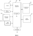
FIG. 8 is a block diagram illustrating a device for searching for a CORESET of RMSI, according to an exemplary embodiment. - Reference will now be made in detail to exemplary embodiments, examples of which are illustrated in the accompanying drawings. The following description refers to the accompanying drawings in which the same numbers in different drawings represent the same or similar elements unless otherwise represented. The implementations set forth in the following description of exemplary embodiments do not represent all implementations consistent with the disclosure. Instead, they are merely examples of devices and methods consistent with aspects related to the disclosure as recited in the appended claims.
-
FIG. 1 is a flowchart showing a method for indicating period information of a CORESET of RMSI, according to an exemplary embodiment of the disclosure. This embodiment is described from a base station side. As shown inFig. 1 , the method for indicating period information of a CORESET of RMSI includes the following steps. - In block S101, indication information is added to a PBCH of an SSB. The indication information includes first indication information configured to indicate a positional relationship between a half radio frame where a CORESET of RMSI corresponding to the SSB is located and a half radio frame where the SSB is located.
- The SSB may be an SS Block or a PBCH Block. The first indication information may occupy different bits, for example, may occupy one bit or two bits.
- In this embodiment, for periods of a CORESET of RMSI that have different magnitudes or sizes, the first indication information having the same content may represent different meanings. For example, if a value of a period of the CORESET of the RMSI is 10 milliseconds (ms) and the first indication information occupies one bit, when a value of the bit is 0, it may indicate that the SSB and the CORESET of the RMSI corresponding to the SSB are located in the same half radio frame. When the value of bit is 1, it may indicate that the CORESET of the RMSI corresponding to the SSB is located in a next half radio frame to that of the SSB. For example, if a value of the period of the CORESET of the RMSI is 20ms and the first indication information occupies one bit, when the value of the bit is 0, it may indicate that the SSB is located in a current half radio frame, and the CORESET of the RMSI corresponding to the SSB is located in a next half radio frame. When the value of the bit is 1, it may indicate that the SSB is located in the (n+2)th half radio frame and the CORESET of the RMSI corresponding to the SSB is located in the (n+3)th half radio frame.
- In addition, for periods of a CORESET of RMSI that have the same size, a positional relationship between the half radio frame where the CORESET of the RMSI corresponding to the SSB is located and the half radio frame where the SSB is located may be represented by first indication information occupying different bits. For example, the positional relationship therebetween may be represented by the first indication information of 1 bit. The positional relationship therebetween may be represented by the first indication information of 2 bits. The use of the first indication information of 2 bits may increase the flexibility of indication.
- In this embodiment, the indication information may further include second indication information configured to indicate a size relationship between a value of a period of the CORESET of the RMSI and a value of a period of the SSB. The value of the period of the CORESET of the RMSI is greater than or equal to the value of the period of the SSB (a maximum period value of the CORESET of the RMSI does not exceed 320ms), and there is a certain relationship between the value of the period of the CORESET of the RMSI and the value of the period of the SSB. For example, Table 1 shows a correspondence between multiple period values of a CORESET of RMSI and multiple period values of an SSB.
Table 1 Correspondence between period of CORESET of RMSI and period of SSB Period of SSB (ms) Period of CORESET of RMSI (ms) 00 01 10 11 5 5 10 20 40 10 10 20 40 80 20 20 40 80 160 40 40 80 160 320 80 80 160 320 X - It can be seen from Table 1 that the period of the CORESET of the RMSI may be 1, 2, 4, or 8 times the value of the period of the SSB. Therefore, the second indication information may be represented by 2 bits, and fewer bits are used.
- In addition, in this embodiment, the period information of the CORESET of the RMSI may include a positional relationship between the half radio frame where the CORESET of the RMSI is located and the half radio frame where the corresponding SSB is located, and the value of the period of the CORESET of the RMSI.
- In block S102, the SSB carrying the indication information is sent to a UE in a beam scanning manner.
- In this embodiment, after the indication information is added to the PBCH of the SSB, the SSB carrying the indication information may be sent to a UE in a beam scanning manner.
- In the foregoing embodiment, first indication information, that is configured to indicate a positional relationship between a half radio frame where a CORESET of RMSI corresponding to the SSB is located and a half radio frame where the SSB is located, is added to a PBCH of an SSB, so as to indicate period information of a CORESET of RMSI by using as few bits as possible.
-
FIG. 2 is a flowchart showing a method for searching for a CORESET of RMSI, according to an exemplary embodiment of the disclosure. This embodiment is described from a UE side. As shown inFig. 2 , the method for searching for a CORESET of RMSI includes the following steps. - In block S201, an SSB carrying indication information sent by a base station is received by the UE. The indication information includes first indication information configured to indicate a positional relationship between a half radio frame where a CORESET of RMSI corresponding to the SSB is located and a half radio frame where the SSB is located.
- The first indication information may occupy different bits, for example, one or two bits.
- In this embodiment, the indication information may further include second indication information configured to indicate a size relationship between a value of a period of the CORESET of the RMSI and a value of a period of the SSB.
- In block S202, a half radio frame where the CORESET of the RMSI is located is obtained by the UE according to a half radio frame where the SSB is located and the first indication information.
- In this embodiment, if the indication information further includes second indication information, the UE firstly obtains the value of the period of the CORESET of the RMSI according to the value of the period of the SSB and the second indication information, and then obtains the half radio frame where the CORESET of the RMSI is located according to the half radio frame where the SSB is located and the first indication information.
- Because the second indication information occupies fewer bits, the period of the CORESET of the RMSI can be obtained by using a fewer number of times.
- In block S203, the CORESET of the RMSI is searched for in the half radio frame where the CORESET of the RMSI is located.
- After the UE obtains the half radio frame where the CORESET of the RMSI is located, the UE may search for or find the CORESET of the RMSI in the half radio frame where the CORESET of the RMSI is located.
- In the foregoing embodiment, the half radio frame where the CORESET of the RMSI is located is obtained according to the half radio frame where the SSB is located and the first indication information carried in the received SSB, and the CORESET of the RMSI is searched for in the half radio frame where the CORESET of the RMSI is located. The entire implementation process realizes indication of the period information of the CORESET of the RMSI by using fewer bits, resulting in the frequency of a UE searching for the half radio frame where the CORESET of the RMSI is located to be reduced, thereby improving the search efficiency of the CORESET of the RMSI.
-
FIG. 3 is a signaling flowchart showing a method for searching for a CORESET of RMSI, according to an exemplary embodiment of the disclosure. This embodiment is described on the basis of interaction between a base station and UE. As shown inFIG. 3 , the method includes the following steps. - In block S301, the base station adds indication information to a PBCH of an SSB. The indication information includes first indication information and second indication information. The first indication information is configured to indicate a positional relationship between a half radio frame where a CORESET of RMSI corresponding to the SSB is located and a half radio frame where the SSB is located. The second indication information is configured to indicate a size relationship between a value of a period of the CORESET of the RMSI and a value of a period of the SSB.
- In block S302, the base station sends the SSB carrying the indication information to the UE in a beam scanning manner.
- In block S303, the UE receives the SSB carrying the indication information sent by the base station.
- In block S304, the UE obtains the period of a CORESET of RMSI according to the period of the SSB and the second indication information, and obtains the half radio frame where the CORESET of the RMSI is located according to the half radio frame where the SSB is located and the first indication information.
- In block S305, the UE searches for the CORESET of the RMSI in the half radio frame where the CORESET of the RMSI is located.
- In the foregoing embodiment, through interaction between the base station and the UE, the period information of the CORESET of the RMSI can be indicated by using as few bits as possible, and the search efficiency for the CORESET of the RMSI can be improved.
-
FIG. 4 is a block diagram illustrating a device for indicating period information of a CORESET of RMSI, according to an exemplary embodiment. The device may be located in a base station. As shown inFIG. 4 , the device includes anaddition module 41 and a sendingmodule 42. - The
addition module 41 is configured to add indication information to a PBCH of an SSB. The indication information includes first indication information configured to indicate a positional relationship between a half radio frame where a CORESET of RMSI corresponding to the SSB is located and a half radio frame where the SSB is located. - The first indication information may occupy different bits, for example, may occupy one bit or two bits.
- In this embodiment, for periods of a CORESET of RMSI that have different sizes, the first indication information having the same content may represent different meanings. For example, if a value of a period of the CORESET of the RMSI is 10 milliseconds (ms) and the first indication information occupies one bit, when the value of the bit is 0, it may indicate that the SSB and the CORESET of the RMSI corresponding to the SSB are located in the same half radio frame. When the value of the bit is 1, it may indicate that the CORESET of the RMSI corresponding to the SSB is located in a next half radio frame to that of the SSB. For example, if the value of the period of the CORESET of the RMSI is 20 milliseconds (ms) and the first indication information occupies one bit, when the value of the bit is 0, it may indicate that the SSB is located in a current half radio frame, and the CORESET of the RMSI corresponding to the SSB is located in a next half radio frame. When the value of the bit is 1, it may indicate that the SSB is located in an (n+2)th half radio frame and the CORESET of the RMSI corresponding to the SSB is located in an (n+3)th half radio frame.
- In addition, for periods of a CORESET of RMSI that have the same size, a positional relationship between the half radio frame where the CORESET of the RMSI corresponding to the SSB is located and the half radio frame where the SSB is located may be represented by first indication information occupying different bits. For example, the positional relationship therebetween may be represented by the first indication information of 1 bit. The positional relationship therebetween may be represented by the first indication information of 2 bits. The use of the first indication information of 2 bits may increase the flexibility of indication.
- In this embodiment, the indication information may further include second indication information configured to indicate a size relationship between the value of the period of the CORESET of the RMSI and the value of the period of the SSB. The value of the period of the CORESET of the RMSI is greater than or equal to the value of the period of the SSB (a maximum period value of the CORESET of the RMSI does not exceed 320ms), and there is a certain relationship between the value of the period of the CORESET of the RMSI and the value of the period of the SSB. For example, Table 1 shows a correspondence between multiple period values of a CORESET of RMSI and multiple period values of an SSB.
- It can be seen from Table 1 that the period of the CORESET of the RMSI may be 1, 2, 4, or 8 times the period of the SSB. Therefore, the second indication information may be represented by 2 bits, and fewer bits are used.
- In addition, in this embodiment, the period information of the CORESET of the RMSI may include a positional relationship between the half radio frame where the CORESET of the RMSI is located and the half radio frame where the corresponding SSB is located, and the period of the CORESET of the RMSI.
- The sending
module 42 is configured to send, in a beam scanning manner, the SSB carrying the indication information added by theaddition module 41 to a UE. - In this embodiment, after the indication information is added to the PBCH of the SSB, the SSB carrying the indication information may be sent to a UE in a beam scanning manner.
- In the foregoing embodiment, first indication information, that is configured to indicate a positional relationship between a half radio frame where a CORESET of RMSI corresponding to the SSB is located and a half radio frame where the SSB is located, is added to a PBCH of an SSB, so as to indicate period information of a CORESET of RMSI by using as few bits as possible.
-
FIG. 5 is a block diagram illustrating a device for searching for a CORESET of RMSI, according to an exemplary embodiment. The device may be applied in a UE. As shown inFIG. 5 , the device includes a receivingmodule 51, a first obtainingmodule 52 and asearch module 53. - The receiving
module 51 is configured to receive an SSB carrying indication information sent by a base station. The indication information includes first indication information configured to indicate a positional relationship between a half radio frame where a CORESET of RMSI corresponding to the SSB is located and a half radio frame where the SSB is located. - The first indication information may occupy different bits, for example, may occupy one bit or two bits.
- In this embodiment, the indication information may further include second indication information configured to indicate a size relationship between a value of a period of the CORESET of the RMSI and a value of a period of the SSB.
- The first obtaining
module 52 is configured to obtain, according to a half radio frame where the SSB is located and the first indication information carried in the SSB received by the receivingmodule 51, a half radio frame where the CORESET of the RMSI is located. - The
search module 53 is configured to search for the CORESET of the RMSI in the half radio frame where the CORESET of the RMSI obtained by the first obtainingmodule 52 is located. - After the UE obtains the half radio frame where the CORESET of the RMSI is located, the UE may search for the CORESET of the RMSI in the half radio frame where the CORESET of the RMSI is located.
- In the foregoing embodiment, the half radio frame where the CORESET of the RMSI is located is obtained according to the half radio frame where the SSB is located and the first indication information carried in the received SSB, and the CORESET of the RMSI is searched in the half radio frame where the CORESET of the RMSI is located. The entire implementation process realizes indication of the period information of the CORESET of the RMSI by using fewer bits, resulting in the frequency of a UE searching for the half radio frame where the CORESET of the RMSI is located, thereby improving the search efficiency of the CORESET of the RMSI.
-
FIG. 6 is a block diagram illustrating another device for searching for a CORESET of RMSI, according to an exemplary embodiment. As shown inFIG. 6 , on the basis of the foregoing embodiment shown inFIG. 5 , the device may further include a second obtainingmodule 54. - The second obtaining
module 54 is configured to obtain, before the first obtainingmodule 52 obtains the half radio frame where the CORESET of the RMSI is located according to the half radio frame where the SSB is located and the first indication information, a value of a period of the CORESET of the RMSI according to a value of a period of the SSB and the second indication information. - In this embodiment, if the indication information further includes second indication information, the UE firstly obtains the period of the CORESET of the RMSI according to the period of the SSB and the second indication information, and then obtains the half radio frame where the CORESET of the RMSI is located according to the half radio frame where the SSB is located and the first indication information.
- In the foregoing embodiment, the period of the CORESET of the RMSI is obtained according to the period of the SSB and the second indication information. Since the second indication information occupies few bits, it takes a fewer number of times to obtain the period of the CORESET of the RMSI.
-
FIG. 7 is a block diagram illustrating a device for indicating period information of a CORESET of RMSI, according to an exemplary embodiment. Adevice 700 may be provided as a base station. Referring toFIG. 7 , thedevice 700 includes aprocessing component 722, a wireless transmitting/receiving component 724, anantenna component 726, and a wireless interface-specific signal processing portion. Theprocessing component 722 may further include one or more processors. - One of the processors in the
processing component 722 may be configured to: - add indication information to a PBCH of an SSB, the indication information including first indication information configured to indicate a positional relationship between a half radio frame where a CORESET of RMSI corresponding to the SSB is located and a half radio frame where the SSB is located; and
- send, in a beam scanning manner, the SSB carrying the indication information to a UE.
- In some embodiments, there is also provided a non-transitory computer-readable storage medium including instructions, executable by the
processor 722 of thedevice 700 to complete the above described method for indicating period information of a CORESET of RMSI. For example, the non-transitory computer-readable storage medium may be a Read-Only Memory (ROM), a Random Access Memory (RAM), a Compact Disc Read-Only Memory (CD-ROM), a magnetic tape, a floppy disc, an optical data storage device and the like. -
FIG. 8 is a block diagram illustrating a device for indicating period information of a CORESET of RMSI, according to an exemplary embodiment. For example, adevice 800 may be a UE such as a mobile phone, a computer, a digital broadcast terminal, a messaging device, a gaming console, a tablet, a medical device, exercise equipment, and a personal digital assistant. - Referring to
FIG. 8 , thedevice 800 may include one or more of the following components: aprocessing component 802, amemory 804, apower component 806, amultimedia component 808, anaudio component 810, an Input/Output (I/O)interface 812, asensor component 814, and acommunication component 816. - The
processing component 802 typically controls overall operations of thedevice 800, such as operations associated with display, telephone calls, data communications, camera operations, and recording operations. Theprocessing component 802 may include one ormore processors 820 to execute instructions to perform all or part of the steps in the above described methods. Moreover, theprocessing component 802 may include one or more modules which facilitate the interactions between theprocessing component 802 and other components. For example, theprocessing component 802 may include a multimedia module to facilitate the interaction between themultimedia component 808 and theprocessing component 802. - One of the
processors 820 in theprocessing component 802 may be configured to: - receive an SSB carrying indication information sent by a base station, the indication information including first indication information configured to indicate a positional relationship between a half radio frame where a CORESET of RMSI corresponding to the SSB is located and a half radio frame where the SSB is located;
- obtain the half radio frame where the CORESET of the RMSI is located according to the half radio frame where the SSB is located and the first indication information; and
- search for the CORESET of the RMSI in the half radio frame where the CORESET of the RMSI is located.
- The
memory 804 is configured to store various types of data to support the operation of thedevice 800. Examples of such data include instructions for any applications or methods operated on thedevice 800, contact data, phonebook data, messages, pictures, video, etc. Thememory 804 may be implemented using any type of volatile or non-volatile memory devices, or a combination thereof, such as a Static Random Access Memory (SRAM), an Electrically Erasable Programmable Read-Only Memory (EEPROM), an Erasable Programmable Read-Only Memory (EPROM), a Programmable Read-Only Memory (PROM), a Read-Only Memory (ROM), a magnetic memory, a flash memory, a magnetic or optical disk. - The
power component 806 provides power to various components of thedevice 800. Thepower component 806 may include: a power management system, one or more power sources, and any other components associated with the generation, management and distribution of power in thedevice 800. - The
multimedia component 808 includes a screen providing an output interface between thedevice 800 and the user. In some embodiments, the screen may include a Liquid Crystal Display (LCD) and a Touch Panel (TP). If the screen includes the TP, the screen may be implemented as a touch screen to receive input signals from the user. The TP includes one or more touch sensors to sense touches, swipes and gestures on the TP. The touch sensors may not only sense a boundary of a touch or swipe action, but also sense a period of time and a pressure associated with the touch or swipe action. In some embodiments, themultimedia component 808 includes a front camera and/or a rear camera. The front camera and/or the rear camera may receive an external multimedia datum while thedevice 800 is in an operation mode, such as a photographing mode or a video mode. Each of the front camera and the rear camera may be a fixed optical lens system or have focus and optical zoom capability. - The
audio component 810 is configured to output and/or input audio signals. For example, theaudio component 810 includes a Microphone (MIC) configured to receive an external audio signal when thedevice 800 is in an operation mode, such as a call mode, a recording mode, and a voice recognition mode. The received audio signal may be further stored in thememory 804 or transmitted via thecommunication component 816. In some embodiments, theaudio component 810 further includes a speaker to output audio signals. - The I/
O interface 812 provides an interface between theprocessing component 802 and peripheral interface modules, such as a keyboard, a click wheel, or buttons. The buttons may include, but are not limited to, a home button, a volume button, a starting button, and a locking button. - The
sensor component 814 includes one or more sensors to provide status assessments of various aspects of thedevice 800. For example, thesensor component 814 may detect an open/closed status of thedevice 800, and relative positioning of components. For example, the component is the display and the keypad of thedevice 800. Thesensor component 814 may also detect a change in position of thedevice 800 or a component of thedevice 800, a presence or absence of user contact with thedevice 800, an orientation or an acceleration/deceleration of thedevice 800, and a change in temperature of thedevice 800. Thesensor component 814 may include a proximity sensor configured to detect the presence of nearby objects without any physical contact. Thesensor component 814 may also include a light sensor, such as a Complementary Metal Oxide Semiconductor (CMOS) or Charge Coupled Device (CCD) image sensor, for use in imaging applications. In some embodiments, thesensor component 814 may also include an acceleration sensor, a gyroscope sensor, a magnetic sensor, a pressure sensor, or a temperature sensor. - The
communication component 816 is configured to facilitate communication, wired or wirelessly, between thedevice 800 and other devices. Thedevice 800 may access a wireless network based on a communication standard, such as WiFi, 2G or 3G, or a combination thereof. In one exemplary embodiment, thecommunication component 816 receives a broadcast signal or broadcast associated information from an external broadcast management system via a broadcast channel. In one exemplary embodiment, thecommunication component 816 further includes a Near Field Communication (NFC) module to facilitate short-range communications. For example, the NFC module may be implemented based on a Radio Frequency Identification (RFID) technology, an Infrared Data Association (IrDA) technology, an Ultra-Wideband (UWB) technology, a Bluetooth (BT) technology, and other technologies. - In some embodiments, the
device 800 may be implemented with one or more Application Specific Integrated Circuits (ASICs), Digital Signal Processors (DSPs), Digital Signal Processing Devices (DSPDs), Programmable Logic Devices (PLDs), Field Programmable Gate Arrays (FPGAs), controllers, micro-controllers, microprocessors, or other electronic elements, for performing the above described methods. - In some embodiments, there is also provided a non-transitory computer-readable storage medium including instructions, such as being included in the
memory 804, executable by theprocessor 820 of thedevice 800 to complete the above described methods. For example, the non-transitory computer-readable storage medium may be a ROM, a RAM, a CD-ROM, a magnetic tape, a floppy disc, an optical data storage device and the like. - The device embodiments substantially correspond to the method embodiments, and thus reference for related parts may be made to part of descriptions of the method embodiments. The device embodiment described above is only schematic. Units described as separate parts therein may or may not be physically separated. Parts displayed as units may or may not be physical units, and namely may be located in the same place or may also be distributed to a plurality of network units. Part or all of the modules therein may be selected according to a practical requirement to achieve the purpose of the solutions of the embodiments. Those of ordinary skill in the art may understand and implement without creative work.
- It is to be noted that relational terms "first", "second" and the like in the disclosure are adopted only to distinguish one entity or operation from another entity or operation and not always to require or imply existence of any such practical relationship or sequence between the entities or operations. Terms "include" and "comprise" or any other variation thereof is intended to cover nonexclusive inclusions, so that a process, method, object or device including a series of elements not only includes those elements, but also includes other elements that are not clearly listed, or further includes elements intrinsic to the process, the method, the object or the device. Under the condition of no more limitations, an element defined by statement "including a/an......" does not exclude existence of another element that is the same in a process, method, object or device including the element.
- Other embodiments of the disclosure will be apparent to those skilled in the art from consideration of the specification and practice of the disclosure disclosed here. The disclosure is intended to cover any variations, uses, or adaptations of the disclosure following the general principles thereof and including such departures from the disclosure as come within known or customary practice in the art. It is intended that the specification and examples be considered as exemplary only, with a true scope and spirit of the disclosure being indicated by the following claims.
- It will be appreciated that the disclosure is not limited to the exact construction that has been described above and illustrated in the accompanying drawings, and that various modifications and changes can be made without departing from the scope thereof. It is intended that the scope of the disclosure only be limited by the appended claims.
Claims (18)
- A method for indicating period information of a common control resource set (CORESET) of remaining minimum system information (RMSI), for applying to a base station, the method comprising:adding indication information to a physical broadcast channel (PBCH) of a broadcasted synchronization signal block (SSB), wherein the indication information comprises first indication information configured to indicate a positional relationship between a half radio frame where a CORESET of RMSI corresponding to the SSB is located and a half radio frame where the SSB is located; andsending the SSB carrying the indication information to user equipment (UE) in a beam scanning manner.
- The method of claim 1, wherein the indication information further comprises second indication information configured to indicate a size relationship between a value of a period of the CORESET of the RMSI and a value of a period of the SSB.
- The method of claim 1, wherein the first indication information occupies one bit or two bits.
- A method for searching for a common control resource set (CORESET) of remaining minimum system information (RMSI), for applying to User Equipment (UE), the method comprising:receiving a broadcasted synchronization signal block (SSB) carrying indication information from a base station, wherein the indication information comprises first indication information configured to indicate a positional relationship between a half radio frame where a CORESET of RMSI corresponding to the SSB is located and a half radio frame where the SSB is located;obtaining the half radio frame where the CORESET of the RMSI is located according to the half radio frame where the SSB is located and the first indication information; andsearching for the CORESET of the RMSI in the half radio frame where the CORESET of the RMSI is located.
- The method of claim 4, wherein the indication information further comprises second indication information configured to indicate a size relationship between a value of a period of the CORESET of the RMSI and a value of a period of the SSB.
- The method of claim 4, wherein the first indication information occupies one bit or two bits.
- The method of claim 5, wherein the method comprises:
before obtaining the half radio frame where the CORESET of the RMSI is located according to the half radio frame where the SSB is located and the first indication information, obtaining the value of the period of the CORESET of the RMSI according to the value of period of the SSB and the second indication information. - A device for indicating period information of a common control resource set (CORESET) of remaining minimum system information (RMSI), for applying to a base station, the device comprising:an addition module, configured to add indication information to a physical broadcast channel (PBCH) of a broadcasted synchronization signal block (SSB), wherein the indication information comprises first indication information configured to indicate a positional relationship between a half radio frame where a CORESET of RMSI corresponding to the SSB is located and a half radio frame where the SSB is located; anda sending module, configured to send the SSB carrying the indication information added by the addition module to user equipment (UE) in a beam scanning manner.
- The device of claim 8, wherein the indication information further comprises second indication information configured to indicate a size relationship between a value of a period of the CORESET of the RMSI and a value of a period of the SSB.
- The device of claim 8, wherein the first indication information occupies one bit or two bits.
- A device for searching for a common control resource set (CORESET) of remaining minimum system information (RMSI), for applying to user equipment (UE), the device comprising:a receiving module, configured to receive a broadcasted synchronization signal block (SSB) carrying indication information from a base station, wherein the indication information comprises first indication information configured to indicate a positional relationship between a half radio frame where a CORESET of RMSI corresponding to the SSB is located and a half radio frame where the SSB is located;a first obtaining module, configured to obtain the half radio frame where the CORESET of the RMSI is located according to the half radio frame where the SSB is located and the first indication information that is carried in the SSB received by the receiving module; anda search module, configured to search for the CORESET of the RMSI in the half radio frame where the CORESET of the RMSI obtained by the first obtaining module is located.
- The device of claim 11, wherein the indication information further comprises second indication information configured to indicate a size relationship between a value of a period of the CORESET of the RMSI and a value of a period of the SSB.
- The device of claim 11, wherein the first indication information occupies one bit or two bits.
- The device of claim 12, further comprising:
a second obtaining module, configured to obtain, before the first obtaining module obtains the half radio frame where the CORESET of the RMSI is located according to the half radio frame where the SSB is located and the first indication information, the value of period of the CORESET of the RMSI according to the period of the SSB and the second indication information. - Abase station, comprising:a processor; anda memory configured to store instructions executable by the processor,wherein the processor is configured to:add indication information to a physical broadcast channel (PBCH) of a broadcasted synchronization signal block (SSB), wherein the indication information comprises first indication information configured to indicate a positional relationship between a half radio frame where a common control resource set (CORESET) of remaining minimum system information (RMSI) corresponding to the SSB is located and a half radio frame where the SSB is located; andsend the SSB carrying the indication information to User Equipment (UE) in a beam scanning manner.
- User equipment (UE), comprising:a processor; anda memory configured to store instructions executable by the processor,wherein the processor is configured to:receive a broadcasted synchronization signal block (SSB) carrying indication information sent by a base station, wherein the indication information comprises first indication information configured to indicate a positional relationship between a half radio frame where a common control resource set (CORESET) of remaining minimum system information (RMSI) corresponding to the SSB is located and a half radio frame where the SSB is located;obtain the half radio frame where the CORESET of the RMSI is located according to a half radio frame where the SSB is located and the first indication information; andsearch for the CORESET of the RMSI in the half radio frame where the CORESET of the RMSI is located.
- A computer-readable storage medium, having stored thereon computer instructions that, when being executed by a processor, implement the steps of the method for indicating period information of a common control resource set (CORESET) of remaining minimum system information (RMSI) of claim 1.
- A computer-readable storage medium, having stored thereon computer instructions that, when being executed by a processor, implement the steps of the method for search for a common control resource set (CORESET) of remaining minimum system information (RMSI) of claim 4.
Applications Claiming Priority (1)
| Application Number | Priority Date | Filing Date | Title |
|---|---|---|---|
| PCT/CN2017/111084 WO2019095140A1 (en) | 2017-11-15 | 2017-11-15 | Period information indication method for common control resource set of remaining key system information |
Publications (4)
| Publication Number | Publication Date |
|---|---|
| EP3709732A1 true EP3709732A1 (en) | 2020-09-16 |
| EP3709732A4 EP3709732A4 (en) | 2021-07-21 |
| EP3709732C0 EP3709732C0 (en) | 2023-07-26 |
| EP3709732B1 EP3709732B1 (en) | 2023-07-26 |
Family
ID=62142037
Family Applications (1)
| Application Number | Title | Priority Date | Filing Date |
|---|---|---|---|
| EP17932403.3A Active EP3709732B1 (en) | 2017-11-15 | 2017-11-15 | Period information indication method for common control resource set of remaining key system information |
Country Status (5)
| Country | Link |
|---|---|
| US (1) | US11770781B2 (en) |
| EP (1) | EP3709732B1 (en) |
| CN (1) | CN108064466B (en) |
| ES (1) | ES2954302T3 (en) |
| WO (1) | WO2019095140A1 (en) |
Families Citing this family (13)
| Publication number | Priority date | Publication date | Assignee | Title |
|---|---|---|---|---|
| CN117793919A (en) | 2017-11-17 | 2024-03-29 | 中兴通讯股份有限公司 | Information sending and receiving method and device |
| CN110691413A (en) * | 2018-07-04 | 2020-01-14 | 普天信息技术有限公司 | Method and equipment for transmitting residual minimum system information control resource set |
| CN112425247B (en) * | 2018-07-17 | 2024-07-05 | 上海诺基亚贝尔股份有限公司 | Synchronization signal block and residual minimum system information location reporting in NR measurements |
| CN110753394B (en) * | 2018-07-23 | 2023-03-31 | 中国移动通信有限公司研究院 | Information transmitting method, information receiving method, terminal, network device and computer storage medium |
| CN110830187B (en) * | 2018-08-07 | 2021-08-17 | 维沃移动通信有限公司 | Information transmission indication method, network equipment and terminal |
| CN110831151B (en) * | 2018-08-09 | 2022-05-10 | 中国移动通信有限公司研究院 | Method, device and computer readable storage medium for determining paging position |
| CN110830402B (en) * | 2018-08-09 | 2022-05-27 | 大唐移动通信设备有限公司 | Method and device for sending and detecting synchronous broadcast information |
| CN112753262A (en) | 2018-09-27 | 2021-05-04 | Oppo广东移动通信有限公司 | Information processing method, device and storage medium |
| CN110972238B (en) * | 2018-09-28 | 2021-06-22 | 华为技术有限公司 | Communication method and device |
| CN110971322B (en) * | 2018-09-30 | 2022-02-15 | 维沃移动通信有限公司 | Information transmission method, network equipment and terminal |
| CN109565649B (en) * | 2018-11-01 | 2021-09-14 | 北京小米移动软件有限公司 | Method and device for transmitting synchronization indication information |
| CN112369093B (en) * | 2018-11-30 | 2023-09-12 | Oppo广东移动通信有限公司 | Method, equipment, chip and medium for determining SSB transmission mode of synchronous signal block |
| CN110463258B (en) * | 2019-06-28 | 2022-07-22 | 北京小米移动软件有限公司 | Initial access indication method, device and storage medium |
Family Cites Families (33)
| Publication number | Priority date | Publication date | Assignee | Title |
|---|---|---|---|---|
| US7894417B2 (en) | 2005-11-01 | 2011-02-22 | Nokia Corporation | Signal arrangement for multi-bandwidth OFDM system |
| JP4869778B2 (en) | 2006-01-18 | 2012-02-08 | 株式会社エヌ・ティ・ティ・ドコモ | Transmitting apparatus, receiving apparatus, and communication method |
| RU2428815C2 (en) | 2006-01-18 | 2011-09-10 | Нтт Досомо, Инк. | Transmitter, receiver and method of communication |
| CN101578775B (en) | 2007-01-04 | 2013-08-28 | 高通股份有限公司 | Method and apparatus for utilizing other sector interference (OSI) indication |
| CN101453243B (en) | 2007-11-30 | 2012-07-04 | 华为技术有限公司 | Method, equipment and system for on-line reconfiguration control |
| US8442069B2 (en) | 2008-04-14 | 2013-05-14 | Qualcomm Incorporated | System and method to enable uplink control for restricted association networks |
| KR101557400B1 (en) | 2008-11-18 | 2015-10-05 | 삼성전자주식회사 | Apparatus and method for system information receiving in mobile communication terminal |
| US9286312B2 (en) | 2012-04-13 | 2016-03-15 | Massachusetts Institute Of Technology | Data coreset compression |
| CN109921890A (en) | 2012-09-26 | 2019-06-21 | 华为技术有限公司 | A kind of control channel detection method and user equipment |
| WO2014067146A1 (en) | 2012-11-02 | 2014-05-08 | 华为技术有限公司 | Control channel detection method and device |
| JP6179589B2 (en) | 2013-04-04 | 2017-08-16 | 富士通株式会社 | Mobile communication system, mobile station, base station, and cell detection method |
| EP2787671B1 (en) | 2013-04-05 | 2018-10-03 | Alcatel Lucent | Downlink communication with repetition transmissions |
| US9736829B2 (en) | 2013-10-14 | 2017-08-15 | Qualcomm Incorporated | Downlink control management in an unlicensed or shared spectrum |
| US20150201249A1 (en) | 2014-01-10 | 2015-07-16 | Samsung Electronics Co., Ltd. | Method and apparatus for receiving broadcasting channel |
| EP3354097B1 (en) | 2015-09-23 | 2020-04-29 | Telefonaktiebolaget LM Ericsson (PUBL) | Scheduling and transmitting control information and data for direct communication |
| EP3482596B1 (en) | 2016-08-11 | 2021-10-06 | Samsung Electronics Co., Ltd. | Method and apparatus of data transmission in next generation cellular networks |
| US10159097B2 (en) | 2016-09-30 | 2018-12-18 | Qualcomm Incorporated | Signaling and determination of slot and mini-slot structure |
| WO2018082017A1 (en) | 2016-11-04 | 2018-05-11 | Mediatek Singapore Pte. Ltd. | Methods and apparatus for random access procedure in nr system with beamforming |
| CN106851840B (en) | 2017-03-23 | 2021-03-09 | 北京小米移动软件有限公司 | Method, device and system for sending key system information |
| CN107278383B (en) * | 2017-03-28 | 2020-08-14 | 北京小米移动软件有限公司 | Method and device for transmitting and acquiring synchronous information block |
| EP3606133B1 (en) | 2017-05-02 | 2021-08-04 | Guangdong Oppo Mobile Telecommunications Corp., Ltd. | Method and terminal device for transmitting signal |
| US10952273B2 (en) | 2017-08-10 | 2021-03-16 | At&T Intellectual Property I, L.P. | Detecting and correcting radio link failures based on different usage scenarios |
| JP7130030B2 (en) | 2017-08-10 | 2022-09-02 | 中興通訊股▲ふん▼有限公司 | Common control block communication |
| CN109391454B (en) * | 2017-08-11 | 2021-09-14 | 华为技术有限公司 | Information sending and receiving method and device |
| KR102413499B1 (en) | 2017-09-08 | 2022-06-27 | 삼성전자 주식회사 | A method and system for handling radio link monitoring(rlm) using bandwidth part(bwp) configurations |
| WO2019051802A1 (en) * | 2017-09-15 | 2019-03-21 | Oppo广东移动通信有限公司 | Data transmission method, network device and terminal device |
| US10727968B2 (en) * | 2017-09-15 | 2020-07-28 | Qualcomm Incorporated | Synchronization signal block and control resource set multiplexing |
| CN117793925A (en) | 2017-09-19 | 2024-03-29 | 日本电气株式会社 | Method and device for transmitting control information |
| JP7241070B2 (en) | 2017-09-30 | 2023-03-16 | 華為技術有限公司 | Communication method and communication device |
| CN111194574B (en) | 2017-10-06 | 2024-01-16 | 株式会社Ntt都科摩 | Terminal, wireless communication method, base station and system |
| US11082320B2 (en) * | 2017-10-25 | 2021-08-03 | Qualcomm Incorporated | Techniques for RMSI PDCCH transmission and monitoring |
| US10715371B2 (en) * | 2017-11-01 | 2020-07-14 | Samsung Electronics Co., Ltd. | Method and apparatus of NR RMSI coreset configuration in MIB |
| US10728916B2 (en) | 2017-11-17 | 2020-07-28 | Qualcomm Incorporated | Designs for remaining minimum system information (RMSI) control resource set (CORESET) and other system information (OSI) CORESET |
-
2017
- 2017-11-15 US US16/762,657 patent/US11770781B2/en active Active
- 2017-11-15 CN CN201780001841.6A patent/CN108064466B/en active Active
- 2017-11-15 EP EP17932403.3A patent/EP3709732B1/en active Active
- 2017-11-15 WO PCT/CN2017/111084 patent/WO2019095140A1/en unknown
- 2017-11-15 ES ES17932403T patent/ES2954302T3/en active Active
Also Published As
| Publication number | Publication date |
|---|---|
| WO2019095140A1 (en) | 2019-05-23 |
| EP3709732C0 (en) | 2023-07-26 |
| EP3709732A4 (en) | 2021-07-21 |
| ES2954302T3 (en) | 2023-11-21 |
| US20200280938A1 (en) | 2020-09-03 |
| CN108064466A (en) | 2018-05-22 |
| CN108064466B (en) | 2021-12-21 |
| US11770781B2 (en) | 2023-09-26 |
| EP3709732B1 (en) | 2023-07-26 |
Similar Documents
| Publication | Publication Date | Title |
|---|---|---|
| EP3709732B1 (en) | Period information indication method for common control resource set of remaining key system information | |
| US11523369B2 (en) | Signal reception method and apparatus | |
| US11469962B2 (en) | Method and apparatus for configuring information of indicating time-frequency position of SSB, and method and apparatus for determining time-frequency position of SSB | |
| EP3713327B1 (en) | Method for indicating frequency-domain information of common control resource set of remaining minimum system information | |
| US11457437B2 (en) | Method and apparatus for configuring information, base station and user equipment | |
| US11178637B2 (en) | Paging message receiving method and device, and paging configuration method and device | |
| EP3706349A1 (en) | Hybrid automatic repeat request feedback indication and feedback method, device, and base station | |
| US11284398B2 (en) | Communication link configuration method and device | |
| US20230292269A1 (en) | Method and apparatus for determining offset indication, and method and apparatus for determining offset | |
| US12089101B2 (en) | Cell handover method and apparatus, handover configuration method and apparatus, and user equipment | |
| US20220256497A1 (en) | Methods and apparatuses for receiving paging signaling, and methods and apparatuses for transmitting paging signaling | |
| US20240063980A1 (en) | System information reception method and apparatus, and system information transmission method and apparatus | |
| US11012958B2 (en) | Signal transmission method and signal transmission apparatus | |
| US11160012B2 (en) | Methods and devices for notifying system information modification, and computer-readable storage media | |
| EP3726885A1 (en) | Cell reselection method and device, and storage medium | |
| EP3768008A1 (en) | Method and apparatus for indicating and searching for position of synchronous broadcast block of defined cell, and base station | |
| US11218990B2 (en) | Method and apparatus for receiving and sending system information, user equipment and base station | |
| US11297626B2 (en) | Information indication method and apparatus, base station and user equipment | |
| EP3684111B1 (en) | Correspondence indicating and determining method, base station, and user equipment | |
| US11064415B2 (en) | Wireless communication method and apparatus | |
| EP4221361A2 (en) | Method and apparatus for accessing base station | |
| EP3562177A1 (en) | System information transmission method and device | |
| US20200344681A1 (en) | Cell access method and apparatus |
Legal Events
| Date | Code | Title | Description |
|---|---|---|---|
| STAA | Information on the status of an ep patent application or granted ep patent |
Free format text: STATUS: THE INTERNATIONAL PUBLICATION HAS BEEN MADE |
|
| PUAI | Public reference made under article 153(3) epc to a published international application that has entered the european phase |
Free format text: ORIGINAL CODE: 0009012 |
|
| STAA | Information on the status of an ep patent application or granted ep patent |
Free format text: STATUS: REQUEST FOR EXAMINATION WAS MADE |
|
| 17P | Request for examination filed |
Effective date: 20200608 |
|
| AK | Designated contracting states |
Kind code of ref document: A1 Designated state(s): AL AT BE BG CH CY CZ DE DK EE ES FI FR GB GR HR HU IE IS IT LI LT LU LV MC MK MT NL NO PL PT RO RS SE SI SK SM TR |
|
| AX | Request for extension of the european patent |
Extension state: BA ME |
|
| DAV | Request for validation of the european patent (deleted) | ||
| DAX | Request for extension of the european patent (deleted) | ||
| A4 | Supplementary search report drawn up and despatched |
Effective date: 20210621 |
|
| RIC1 | Information provided on ipc code assigned before grant |
Ipc: H04W 72/04 20090101AFI20210615BHEP |
|
| RAP1 | Party data changed (applicant data changed or rights of an application transferred) |
Owner name: KONINKLIJKE PHILIPS N.V. |
|
| REG | Reference to a national code |
Ref country code: DE Ref legal event code: R079 Ref document number: 602017071994 Country of ref document: DE Free format text: PREVIOUS MAIN CLASS: H04W0072040000 Ipc: H04L0005000000 Ref country code: DE Free format text: PREVIOUS MAIN CLASS: H04W0072040000 Ipc: H04L0005000000 |
|
| GRAP | Despatch of communication of intention to grant a patent |
Free format text: ORIGINAL CODE: EPIDOSNIGR1 |
|
| STAA | Information on the status of an ep patent application or granted ep patent |
Free format text: STATUS: GRANT OF PATENT IS INTENDED |
|
| RIC1 | Information provided on ipc code assigned before grant |
Ipc: H04W 48/12 20090101ALI20230124BHEP Ipc: H04L 5/00 20060101AFI20230124BHEP |
|
| INTG | Intention to grant announced |
Effective date: 20230223 |
|
| GRAS | Grant fee paid |
Free format text: ORIGINAL CODE: EPIDOSNIGR3 |
|
| GRAA | (expected) grant |
Free format text: ORIGINAL CODE: 0009210 |
|
| STAA | Information on the status of an ep patent application or granted ep patent |
Free format text: STATUS: THE PATENT HAS BEEN GRANTED |
|
| AK | Designated contracting states |
Kind code of ref document: B1 Designated state(s): AL AT BE BG CH CY CZ DE DK EE ES FI FR GB GR HR HU IE IS IT LI LT LU LV MC MK MT NL NO PL PT RO RS SE SI SK SM TR |
|
| REG | Reference to a national code |
Ref country code: CH Ref legal event code: EP |
|
| REG | Reference to a national code |
Ref country code: IE Ref legal event code: FG4D |
|
| REG | Reference to a national code |
Ref country code: DE Ref legal event code: R096 Ref document number: 602017071994 Country of ref document: DE |
|
| U01 | Request for unitary effect filed |
Effective date: 20230726 |
|
| U07 | Unitary effect registered |
Designated state(s): AT BE BG DE DK EE FI FR IT LT LU LV MT NL PT SE SI Effective date: 20230731 |
|
| REG | Reference to a national code |
Ref country code: LT Ref legal event code: MG9D |
|
| REG | Reference to a national code |
Ref country code: ES Ref legal event code: FG2A Ref document number: 2954302 Country of ref document: ES Kind code of ref document: T3 Effective date: 20231121 |
|
| U20 | Renewal fee paid [unitary effect] |
Year of fee payment: 7 Effective date: 20231130 |
|
| PG25 | Lapsed in a contracting state [announced via postgrant information from national office to epo] |
Ref country code: GR Free format text: LAPSE BECAUSE OF FAILURE TO SUBMIT A TRANSLATION OF THE DESCRIPTION OR TO PAY THE FEE WITHIN THE PRESCRIBED TIME-LIMIT Effective date: 20231027 |
|
| PGFP | Annual fee paid to national office [announced via postgrant information from national office to epo] |
Ref country code: GB Payment date: 20231121 Year of fee payment: 7 |
|
| PGFP | Annual fee paid to national office [announced via postgrant information from national office to epo] |
Ref country code: ES Payment date: 20231219 Year of fee payment: 7 |
|
| PG25 | Lapsed in a contracting state [announced via postgrant information from national office to epo] |
Ref country code: IS Free format text: LAPSE BECAUSE OF FAILURE TO SUBMIT A TRANSLATION OF THE DESCRIPTION OR TO PAY THE FEE WITHIN THE PRESCRIBED TIME-LIMIT Effective date: 20231126 |
|
| PG25 | Lapsed in a contracting state [announced via postgrant information from national office to epo] |
Ref country code: RS Free format text: LAPSE BECAUSE OF FAILURE TO SUBMIT A TRANSLATION OF THE DESCRIPTION OR TO PAY THE FEE WITHIN THE PRESCRIBED TIME-LIMIT Effective date: 20230726 Ref country code: NO Free format text: LAPSE BECAUSE OF FAILURE TO SUBMIT A TRANSLATION OF THE DESCRIPTION OR TO PAY THE FEE WITHIN THE PRESCRIBED TIME-LIMIT Effective date: 20231026 Ref country code: IS Free format text: LAPSE BECAUSE OF FAILURE TO SUBMIT A TRANSLATION OF THE DESCRIPTION OR TO PAY THE FEE WITHIN THE PRESCRIBED TIME-LIMIT Effective date: 20231126 Ref country code: HR Free format text: LAPSE BECAUSE OF FAILURE TO SUBMIT A TRANSLATION OF THE DESCRIPTION OR TO PAY THE FEE WITHIN THE PRESCRIBED TIME-LIMIT Effective date: 20230726 Ref country code: GR Free format text: LAPSE BECAUSE OF FAILURE TO SUBMIT A TRANSLATION OF THE DESCRIPTION OR TO PAY THE FEE WITHIN THE PRESCRIBED TIME-LIMIT Effective date: 20231027 |
|
| PGFP | Annual fee paid to national office [announced via postgrant information from national office to epo] |
Ref country code: TR Payment date: 20231102 Year of fee payment: 7 |
|
| PG25 | Lapsed in a contracting state [announced via postgrant information from national office to epo] |
Ref country code: PL Free format text: LAPSE BECAUSE OF FAILURE TO SUBMIT A TRANSLATION OF THE DESCRIPTION OR TO PAY THE FEE WITHIN THE PRESCRIBED TIME-LIMIT Effective date: 20230726 |
|
| REG | Reference to a national code |
Ref country code: DE Ref legal event code: R097 Ref document number: 602017071994 Country of ref document: DE |
|
| PG25 | Lapsed in a contracting state [announced via postgrant information from national office to epo] |
Ref country code: SM Free format text: LAPSE BECAUSE OF FAILURE TO SUBMIT A TRANSLATION OF THE DESCRIPTION OR TO PAY THE FEE WITHIN THE PRESCRIBED TIME-LIMIT Effective date: 20230726 Ref country code: RO Free format text: LAPSE BECAUSE OF FAILURE TO SUBMIT A TRANSLATION OF THE DESCRIPTION OR TO PAY THE FEE WITHIN THE PRESCRIBED TIME-LIMIT Effective date: 20230726 Ref country code: CZ Free format text: LAPSE BECAUSE OF FAILURE TO SUBMIT A TRANSLATION OF THE DESCRIPTION OR TO PAY THE FEE WITHIN THE PRESCRIBED TIME-LIMIT Effective date: 20230726 Ref country code: SK Free format text: LAPSE BECAUSE OF FAILURE TO SUBMIT A TRANSLATION OF THE DESCRIPTION OR TO PAY THE FEE WITHIN THE PRESCRIBED TIME-LIMIT Effective date: 20230726 |
|
| PLBE | No opposition filed within time limit |
Free format text: ORIGINAL CODE: 0009261 |
|
| STAA | Information on the status of an ep patent application or granted ep patent |
Free format text: STATUS: NO OPPOSITION FILED WITHIN TIME LIMIT |
|
| REG | Reference to a national code |
Ref country code: CH Ref legal event code: PL |
|
| PG25 | Lapsed in a contracting state [announced via postgrant information from national office to epo] |
Ref country code: MC Free format text: LAPSE BECAUSE OF FAILURE TO SUBMIT A TRANSLATION OF THE DESCRIPTION OR TO PAY THE FEE WITHIN THE PRESCRIBED TIME-LIMIT Effective date: 20230726 |
|
| 26N | No opposition filed |
Effective date: 20240429 |
|
| PG25 | Lapsed in a contracting state [announced via postgrant information from national office to epo] |
Ref country code: CH Free format text: LAPSE BECAUSE OF NON-PAYMENT OF DUE FEES Effective date: 20231130 |
|
| PG25 | Lapsed in a contracting state [announced via postgrant information from national office to epo] |
Ref country code: MC Free format text: LAPSE BECAUSE OF FAILURE TO SUBMIT A TRANSLATION OF THE DESCRIPTION OR TO PAY THE FEE WITHIN THE PRESCRIBED TIME-LIMIT Effective date: 20230726 Ref country code: CH Free format text: LAPSE BECAUSE OF NON-PAYMENT OF DUE FEES Effective date: 20231130 |