EP3709552B1 - Verfahren zum senden und empfangen eines steuerungskanals, basisstation und benutzergerät - Google Patents
Verfahren zum senden und empfangen eines steuerungskanals, basisstation und benutzergerät Download PDFInfo
- Publication number
- EP3709552B1 EP3709552B1 EP19216353.3A EP19216353A EP3709552B1 EP 3709552 B1 EP3709552 B1 EP 3709552B1 EP 19216353 A EP19216353 A EP 19216353A EP 3709552 B1 EP3709552 B1 EP 3709552B1
- Authority
- EP
- European Patent Office
- Prior art keywords
- physical resource
- resource elements
- control channel
- physical
- resource element
- Prior art date
- Legal status (The legal status is an assumption and is not a legal conclusion. Google has not performed a legal analysis and makes no representation as to the accuracy of the status listed.)
- Active
Links
Images


Classifications
-
- H—ELECTRICITY
- H04—ELECTRIC COMMUNICATION TECHNIQUE
- H04L—TRANSMISSION OF DIGITAL INFORMATION, e.g. TELEGRAPHIC COMMUNICATION
- H04L5/00—Arrangements affording multiple use of the transmission path
- H04L5/003—Arrangements for allocating sub-channels of the transmission path
- H04L5/0048—Allocation of pilot signals, i.e. of signals known to the receiver
-
- H—ELECTRICITY
- H04—ELECTRIC COMMUNICATION TECHNIQUE
- H04W—WIRELESS COMMUNICATION NETWORKS
- H04W72/00—Local resource management
- H04W72/04—Wireless resource allocation
-
- H—ELECTRICITY
- H04—ELECTRIC COMMUNICATION TECHNIQUE
- H04L—TRANSMISSION OF DIGITAL INFORMATION, e.g. TELEGRAPHIC COMMUNICATION
- H04L5/00—Arrangements affording multiple use of the transmission path
- H04L5/003—Arrangements for allocating sub-channels of the transmission path
- H04L5/0053—Allocation of signalling, i.e. of overhead other than pilot signals
-
- H—ELECTRICITY
- H04—ELECTRIC COMMUNICATION TECHNIQUE
- H04L—TRANSMISSION OF DIGITAL INFORMATION, e.g. TELEGRAPHIC COMMUNICATION
- H04L5/00—Arrangements affording multiple use of the transmission path
- H04L5/003—Arrangements for allocating sub-channels of the transmission path
- H04L5/0058—Allocation criteria
- H04L5/0064—Rate requirement of the data, e.g. scalable bandwidth, data priority
-
- H—ELECTRICITY
- H04—ELECTRIC COMMUNICATION TECHNIQUE
- H04W—WIRELESS COMMUNICATION NETWORKS
- H04W72/00—Local resource management
- H04W72/20—Control channels or signalling for resource management
-
- H—ELECTRICITY
- H04—ELECTRIC COMMUNICATION TECHNIQUE
- H04L—TRANSMISSION OF DIGITAL INFORMATION, e.g. TELEGRAPHIC COMMUNICATION
- H04L5/00—Arrangements affording multiple use of the transmission path
- H04L5/0001—Arrangements for dividing the transmission path
- H04L5/0003—Two-dimensional division
- H04L5/0005—Time-frequency
- H04L5/0007—Time-frequency the frequencies being orthogonal, e.g. OFDM(A) or DMT
- H04L5/001—Time-frequency the frequencies being orthogonal, e.g. OFDM(A) or DMT the frequencies being arranged in component carriers
Definitions
- the present invention relates to a communications technology, and in particular, to methods for transmitting and receiving a control channel, a base station, and a user equipment.
- an orthogonal frequency division multiple access (Orthogonal Frequency Division Multiple Access, OFDMA for short below) manner is generally used as a downlink multiple access mode.
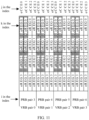
- Downlink resources of the system are divided into orthogonal frequency division multiplexing (Orthogonal Frequency Division Multiple, OFDM for short below) symbols in terms of time, and are divided into subcarriers in terms of frequencies.
- one normal downlink subframe includes two timeslots (slots), where a timeslot includes 7 OFDM symbols, and a normal downlink subframe includes 14 or 12 OFDM symbols in total.
- the LTE Release 8/9/10 standard defines the size of a resource block (Resource Block, RB for short below).
- One RB includes 12 subcarriers in a frequency domain, and includes one half of a subframe duration in a time domain (one timeslot), that is, it includes 7 or 6 OFDM symbols.
- a subcarrier in an OFDM symbol is referred to as a resource element (Resource Element, RE for short below). Therefore, one RB includes 84 or 72 REs.
- a pair of RBs in two timeslots is referred to as a resource block pair (RB pair, RB pair for short below).
- a resource block pair used for physical resources (physical RB pair) is also referred to as a physical resource block pair (Physical RB pair, PRB pair for short below).
- the PRB pair is generally briefed as a PRB. Therefore, the PRB, PRB pair, physical resource block, and physical resource block pair in the following description all refer to a PRB pair.
- Control channels Data of all types borne in a subframe is organized and mapped onto various physical channels based on division of physical time-frequency resources in the subframe.
- Various physical channels may be generally classified into two types: control channels and traffic channels.
- data borne in a control channel may be referred to as control data (or control information), and data borne in a traffic channel may be referred to as service data.
- An ultimate purpose of communication is to transmit service data.
- a function of the control channel is to provide assistance in transmission of service data.
- a complete physical downlink control channel (Physical Downlink Control Channel, PDCCH) is formed by one or more control channel elements (Control Channel Element, CCE for short below), and one CCE is formed by 9 resource element groups (Resource Element Group, REG for short below), where one REG occupies 4 REs.
- PDCCH Physical Downlink Control Channel
- one PDCCH may be formed by 1, 2, 4, or 8 CCEs, respectively corresponding to aggregation level 1, 2, 4, or 8.
- an enhanced physical downlink control channel (Enhanced PDCCH, E-PDCCH for short below) transmitted based on a MIMO precoding mode is introduced.
- the E-PDCCH may be demodulated based on a UE-specific reference signal - demodulation reference signal (Demodulation Reference Signal, DMRS for short below).
- N enhanced control channel elements Enhanced Control Channel Element, eCCE for short below
- eCCE Enhanced Control Channel Element
- E-PDCCHs may be classified into localized (localized) E-PDCCHs and distributed (distributed) E-PDCCHs, where a localized E-PDCCH is transmitted by using a localized transmission mode, and a distributed E-PDCCH is transmitted by using a distributed transmission mode.
- a localized E-PDCCH one control channel is generally located in one PRB pair.
- one eCCE is further divided into at least one enhanced resource element group (Enhanced Resource Element Group, eREG for short below).
- the at least one eREG may be distributed in multiple PRB pairs, so that a frequency diversity gain is obtained.
- interleaving is performed in units of eREGs in the prior art to obtain the position of one distributed E-PDCCH in a PRB pair. It is assumed that a PRB pair includes 4 eCCEs, and that an eCCE includes 4 eREGs. It is assumed that the E-PDCCH of UE1 uses the distributed transmission mode, and is located in 4 PRB pairs with index numbers 3, 4, 8, and 9.
- mapping is performed in units of eREGs, 16 eREGs to which an E-PDCCH at aggregation level 4 is mapped may be located in 16 different eCCEs, and 8 eREGs to which an E-PDCCH at aggregation level 2 is mapped may be located in 8 different eCCEs.
- Abase station (evolved NodeB, eNB for short below) needs to transmit E-PDCCHs to multiple UEs, where some UEs use distributed E-PDCCHs, and some UEs use localized E-PDCCHs.
- E-PDCCH at aggregation level 4 as an example, according to the mapping mode, in the 4 PRB pairs with index numbers 3, 4, 8, and 9, a part of eREGs on each eCCE are occupied by the E-PDCCH of UE1. If the eNB transmits the E-PDCCH to UE1 according to the mapping mode, the eNB cannot transmit a localized E-PDCCH in the 4 PRB pairs. Therefore, the E-PDCCH multiplexing efficiency is relatively low.
- LG ELECTRONICS "On ePDCCH Search Space Design Supporting Localized and Distributed Transmission", 3GPP DRAFT; R1-122309 EPDCCH SS_LG, 3RD GENERATION PARTNERSHIP PROJECT (3GPP), MOBILE COMPETENCE CENTRE ; 650, ROUTE DES LUCIOLES ; F-06921 SOPHIA-ANTIPOLIS CEDEX ; FRANCE, (20120512), vol. RAN WG1, no. Prague, Czech Republic; 20120521 - 20120525 , relates to ePDCCH search space design supporting localized and distributed transmission.
- NEC GROUP "ePDCCH search space design", 3GPP DRAFT; R1-122595, 3RD GENERATION PARTNERSHIP PROJECT (3GPP), MOBILE COMPETENCE CENTRE ; 650, ROUTE DES LUCIOLES ; F-06921 SOPHIA-ANTIPOLIS CEDEX ; FRANCE, (20120512), vol. RAN WG1, no. Prague, Czech Republic; 20120521 - 20120525 , relates to ePDCCH search space design.
- NTT DOCOMO "Resource Mapping Scheme for E-PDCCH", 3GPP DRAFT; R1-121477 MAPPING FOR E-PDCCH, 3RD GENERATION PARTNERSHIP PROJECT (3GPP), MOBILE COMPETENCE CENTRE ; 650, ROUTE DES LUCIOLES ; F-06921 SOPHIA-ANTIPOLIS CEDEX ; FRANCE, (20120320), vol. RAN WG1, no. Jeju, Korea; 20120326 - 20120330 , relates to resource mapping scheme for E-PDCCH.
- the present invention provides methods for transmitting and receiving a control channel, a base station, and a user equipment, so as to improve multiplexing efficiency of E-PDCCHs of different modes.
- the technical effects of the present invention are: at an aggregation level L, when any control channel candidate of a distributed control channel to be transmitted is mapped to physical resources, and some eREGs of the control channel candidate are mapped to a physical resource block pair, these eREGs are preferably mapped to physical resources corresponding to fewest localized eCCEs in the physical resource block pair, thereby improving multiplexing efficiency of control channels of different modes.
- FIG. 1 is a flowchart of an embodiment of a method for transmitting a control channel according to the present invention.
- the method for transmitting a control channel may include: Step 101: Determine m PRB pairs used for transmitting a control channel to be transmitted.
- An i th PRB pair includes n i first physical resource elements, the i th PRB pair includes k i second physical resource elements, and the second physical resource elements included in the m PRB pairs form multiple second physical resource element groups, where the first physical resource elements are used for transmitting the control channel to be transmitted by using a localized transmission mode, and the second physical resource elements are used for transmitting the control channel to be transmitted by using a distributed transmission mode, where m ⁇ 1, n i ⁇ 1, k i ⁇ 1, 0 ⁇ i ⁇ m-1, and m, i, n i , and k i are all integers.
- One of the first physical resource elements includes at least two second physical resource elements, that is, physical resources of the first physical resource element include physical resources of at least two second physical resource elements.
- the control channel may be an E-PDCCH or a PDCCH, which is not limited by this embodiment.
- Step 102 When the control channel to be transmitted is transmitted by using the distributed transmission mode, determine an aggregation level L of the control channel to be transmitted, where L ⁇ 1, and L is an integer.
- Step 103 Determine, according to the aggregation level L, the number G L of second physical resource elements included in each of the second physical resource element groups, where the G L second physical resource elements included in each of the second physical resource element groups are located in ⁇ G L / q ⁇ first physical resource elements in the m PRB pairs, where q indicates the number of second physical resource elements included in one first physical resource element, ⁇ G L / q ⁇ indicates roundup of G L / q , G L ⁇ 1, and G L is an integer.
- Step 104 Determine, according to the aggregation level L, a first control channel candidate at the aggregation level L, where the first control channel candidate corresponds to N L second physical resource element groups, where N L ⁇ 1, and N L is an integer.
- Step 105 Place, on physical resources to which the first control channel candidate is mapped, control information of the control channel to be transmitted, and transmit the control information.
- the G L second physical resource elements are located in one first physical resource element in the m PRB pairs.
- the determining, according to the aggregation level L, the number G L of second physical resource elements included in each of the second physical resource element groups may be: determining the G L according to a preset mapping relationship between the aggregation level L and the number G L of second physical resource elements included in each of the second physical resource element groups.
- higher layer signaling may be transmitted to a receiving device, where the higher layer signaling is used for configuring the number G L corresponding to the aggregation level L, of second physical resource elements included in each of the second physical resource element groups.
- the number G L of second physical resource elements included in a second physical resource element group corresponding to at least one aggregation level is greater than or equal to 2; in this case, the number G L of second physical resource elements included in a second physical resource element group corresponding to at least one aggregation level is greater than or equal to 2, and the G L second physical resource elements included in each of the second physical resource element groups are located in ⁇ G L / q ⁇ first physical resource elements in the m PRB pairs, and therefore, at this aggregation level, each of the second physical resource element groups occupies fewer first physical resource elements, thereby avoiding a case where each second physical resource element in the second physical resource element group occupies one first physical resource element, so that more first physical resource elements may be used in the localized transmission mode; or for at least two aggregation levels in multiple different aggregation levels, a second physical resource element group corresponding to a higher aggregation level in the at least two aggregation levels includes more second
- a performance gain is not great.
- correlation also exists in a frequency domain, and only a limited diversity gain can be obtained in the frequency domain. Therefore, it is unnecessary to distribute the second physical resource elements occupied by the control channel at the higher aggregation level to a lot of PRB pairs, so long as a certain diversity gain is obtained.
- the second physical resource elements occupied by the control channel at the higher aggregation level are distributed to 4 channel-independent PRB pairs in the frequency domain. Therefore, in the case where a certain frequency diversity gain is obtained at each aggregation level, some first physical resource elements are reserved for a localized E-PDCCH.
- all second physical resource elements included in one second physical resource element group are located in one PRB pair; or all second physical resource elements included in all the second physical resource element groups are located on physical resources of a part of first physical resource elements in the m PRB pairs; or in one PRB pair, all second physical resource elements included in one second physical resource element group are located on physical resources of a part of first physical resource elements in the one PRB pair; or in one PRB pair, all second physical resource elements included in all second physical resource element groups are located on physical resources of a part of first physical resource elements in the one PRB pair. Therefore, some first physical resource elements may be used for localized E-PDCCH transmission.
- all second physical resource element groups are formed by physical resources corresponding to a part of antenna ports in the one PRB pair; or in one PRB pair, all second physical resource elements included in all second physical resource element groups are located in first physical resource elements corresponding to a part of antenna ports in the one PRB pair.
- the determining, according to the aggregation level L, a first control channel candidate at the aggregation level L may be: determining, according to the aggregation level L, the number M of control channel candidates at the aggregation level L, where M is an integer, and M ⁇ 1; mapping the M control channel candidates to physical resources in the m PRB pairs; and selecting one first control channel candidate from the M control channel candidates.
- the mapping the M control channel candidates to M ⁇ H L virtual resource elements in the virtual resource element set may be: mapping, according to a pre-obtained start position, the M control channel candidates to M ⁇ H L consecutive virtual resource elements consecutively.
- the sequence numbers of the resource block pairs are sequence numbers of PRB pairs or sequence numbers of virtual resource block pairs; and when the sequence numbers of the resource block pairs are sequence numbers of virtual resource block pairs, a mapping relationship exists between the sequence numbers of the virtual resource block pairs and the sequence numbers of the PRB pairs.
- any control channel candidate of a distributed control channel to be transmitted is mapped to physical resources, and some eREGs of the control channel candidate are mapped to a PRB pair, these eREGs are preferably mapped to physical resources corresponding to fewest localized eCCEs in the PRB pair, thereby improving multiplexing efficiency of control channels of different modes.
- the first physical resource elements may be physical resources corresponding to eCCEs.
- the size of a first physical resource element corresponds to the size of an eCCE, that is, a physical resource element included in one of the first physical resource element may contain one eCCE.
- the second physical resource elements may be physical resources corresponding to eREGs.
- the size of a second physical resource element corresponds to the size of an eREG, or a second physical resource element itself is an eREG.
- control channel to be transmitted may be an E-PDCCH.
- One E-PDCCH may include at least one eCCE.
- the following describes the method for transmitting a control channel according to the embodiment shown in FIG. 1 by using an example where the first physical resource elements are physical resources corresponding to eCCEs, the second physical resource elements are physical resources corresponding to eREGs, and the control channel to be transmitted is an E-PDCCH.
- Step 1 A base station determines m PRB pairs that may be used for transmitting an E-PDCCH to be transmitted, where m ⁇ 1, and m is an integer.
- the physical resources of eCCEs include physical resources of at least two eREGs.
- the localized E-PDCCH and the distributed E-PDCCH include the same number of eREGs, but their specific mappings are different.
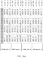
- an E-PDCCH at aggregation level 1 occupies one eCCE. If the E-PDCCH is a localized E-PDCCH, the eREGs of the eCCE are located in one PRB pair; if the E-PDCCH is a distributed E-PDCCH, the eCCE is formed by eREGs located in more than one PRB pair, as shown in FIG. 2(a) and FIG. 2(b) .
- FIG. 2(a) and FIG. 2(b) FIG.
- FIG. 2(a) is a schematic diagram of eCCEs of a localized E-PDCCH
- FIG. 2(b) is a schematic diagram of eCCEs of a distributed E-PDCCH.
- the shadow shows eREGs corresponding to one eCCE of the localized E-PDCCH
- the shadow shows eREGs corresponding to one eCCE of the distributed E-PDCCH.
- each localized eCCE is formed by a column of eREGs in FIG. 2(a) .
- eCCE0 is formed by 4 eREGs numbered eREG0, eREG1, eREG2, and eREG3 in PRB pair 3.
- a distributed E-PDCCH at aggregation level 1 occupies one eCCE, and the eREGs corresponding to the eCCE include eREGs in different PRB pairs, for example, the eCCE may be formed by eREGs having the same number in different PRB pairs.
- eREG0 of PRB pairs numbered 3, 4, 8, and 9 corresponds to an eCCE of a distributed E-PDCCH.
- both the localized and distributed E-PDCCHs define eCCEs and eREGs.
- One eCCE of the localized E-PDCCH and one eCCE of the distributed E-PDCCH correspond to the same number of eREGs.
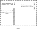
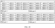
- mapping granularities or interleaving granularities of different aggregation levels are different, as shown in FIG. 3.
- FIG. 3 is a schematic diagram of an embodiment of interleaving granularities of different aggregation levels according to the present invention. In FIG.
- interleaving granularity G 1 of aggregation level 1 is 1 eREG
- interleaving granularity G 2 of aggregation level 2 is 2 eREGs
- interleaving granularities G 4 and G 8 of aggregation levels 4 and 8 are 4 eREGs.
- an interleaving unit is defined as an eREG group; for an E-PDCCH at the aggregation level L, an eREG group includes G L eREGs.
- the size of an eREG group may be predefined, or may also be notified by the base station to a UE through control signaling.
- G L When G L is less than or equal to the number of eREGs corresponding to an eCCE, the G L eREGs are located in one eCCE in the m PRB pairs.
- G L is greater than the number of eREGs corresponding to an eCCE, G L eREGs are located in ⁇ G L / q ⁇ localized eCCEs in the m PRB pairs, where q indicates the number of eREGs included in one eCCE, for example, 4, and ⁇ G L / q ⁇ indicates roundup of G L / q .
- the numbers of eREGs included in eREG groups corresponding to at least two aggregation levels are different.
- the E-PDCCH at the aggregation level L needs to be mapped to H L eREGs.
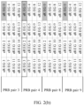
- FIG. 4 is a schematic diagram of an embodiment of eREGs to which distributed E-PDCCHs are mapped according to the present invention.
- physical resources of one eCCE of a distributed E-PDCCH at aggregation level 1 include physical resources corresponding to 4 eREGs in 4 PRB pairs;
- one control channel of a distributed E-PDCCH at aggregation level 2 is formed by 8 eREGs in 4 PRB pairs, but every two eREGs belong to physical resources corresponding to one localized eCCE.
- a binding relationship between the eREGs and demodulation reference signal (Demodulation Reference Signal, DMRS for short below) pilots may reuse the relationship between eCCEs and DMRS pilots in the localized E-PDCCH.
- a pilot port of the eREG is the same as a pilot port corresponding to the eCCE of the localized E-PDCCH.
- a distributed E-PDCCH at aggregation level 1 occupies eREG0, which belongs to eCCE0 of the localized E-PDCCH; in this case, eREG0 uses DMRS port 7.
- Step 2 The base station determines an aggregation level L of the E-PDCCH to be transmitted, and determines, according to the aggregation level L, the number M of control channel candidates, where M ⁇ 1, L ⁇ 1, and M and L are integers.
- Step 3 The base station maps the M control channel candidates to physical resources of the m PRB pairs.
- an eREG group is defined to include 2 eREGs, and therefore, a distributed E-PDCCH at the aggregation level 2 includes 8 eREGs and 4 eREG groups.
- virtual resource elements may be set first, where each of the virtual resource elements corresponds to one eREG on a physical resource.
- the mapping the M control channel candidates to M ⁇ H L virtual resource elements in the virtual resource element set may be: mapping, according to a pre-obtained start position, the M control channel candidates to M ⁇ H L consecutive virtual resource elements consecutively, as shown in FIG. 5.
- FIG. 5 is a schematic diagram of an embodiment of virtual resource elements to which control channel candidates are mapped according to the present invention.
- the preset start position is a virtual resource element numbered T
- control channel candidate 1 is mapped to a virtual resource element numbered T to a virtual resource element numbered T+H L -1
- control channel candidate 2 is mapped to a virtual resource element numbered T+H L to a virtual resource element numbered T+2 ⁇ H L -1.
- control channel candidate M is mapped to a virtual resource element numbered T+(M-1) ⁇ H L to a virtual resource element numbered T+M ⁇ H L -1.
- aggregation level 2 because one virtual resource element corresponds to one eREG on a physical resource, as can be seen from FIG. 4 , the number of virtual resource elements included in each virtual resource element group is 2, and the number of PRB pairs is 4.
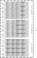
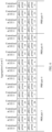
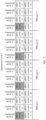
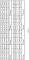
- the 32 virtual resource element groups are sequentially written into the interleaving matrix according to rows, as shown in Table 1.
- Table 1 Virtual resource element group 0 Virtual resource element group 1 Virtual resource element group 2 Virtual resource element group 3 Virtual resource element group 4 Virtual resource element group 5 Virtual resource element group 6 Virtual resource element group 7 Virtual resource element group 8 Virtual resource element group 9 Virtual resource element group 10 Virtual resource element group 11 Virtual resource element group 12 Virtual resource element group 13 Virtual resource element group 14 Virtual resource element group 15 Virtual resource element group 16 Virtual resource element group 17 Virtual resource element group 18 Virtual resource element group 19 Virtual resource element group 20 Virtual resource element group 21 Virtual resource element group 22 Virtual resource element group 23 Virtual resource element group 24 Virtual resource element group 25 Virtual resource element group 26 Virtual resource element group 27 Virtual resource element group 28 Virtual resource element group 29 Virtual resource element group 30 Virtual resource element group 31
- the 32 virtual resource element groups are sequentially read from the interleaving matrix according to columns, and the sequentially read 32 virtual resource element groups are: virtual resource element group 0, virtual resource element group 4, virtual resource element group 8, virtual resource element group 12, virtual resource element group 16, virtual resource element group 20, virtual resource element group 24, virtual resource element group 28, virtual resource element group 1, virtual resource element group 5, virtual resource element group 9, virtual resource element group 13, virtual resource element group 17, virtual resource element group 21, virtual resource element group 25, virtual resource element group 29, virtual resource element group 2, virtual resource element group 6, virtual resource element group 10, virtual resource element group 14, virtual resource element group 18, virtual resource element group 22, virtual resource element group 26, virtual resource element group 30, virtual resource element group 3, virtual resource element group 7, virtual resource element group 11, virtual resource element group 15, virtual resource element group 19, virtual resource element group 23, virtual resource element group 27, and virtual resource element group 31.
- the sequentially read 32 virtual resource element groups form the interleaved virtual resource element set.
- a predefined sequence for example, in ascending or descending order of numbers of virtual resource element groups
- the sequence numbers of the RB pairs are sequence numbers of PRB pairs or sequence numbers of virtual resource block (Virtual RB, VRB for short below) pairs; and when the sequence numbers of the RB pairs are sequence numbers of VRB pairs, a mapping relationship exists between the sequence numbers of the VRB pairs and the sequence numbers of the PRB pairs.
- Virtual RB Virtual RB
- FIG. 6 is a schematic diagram of an embodiment of eREG groups to which virtual resource element groups are mapped according to the present invention.
- a distributed E-PDCCH at aggregation level 2 has 6 control channel candidates.
- 6 control channel candidates occupy eREG groups 0-3, eREG groups 4-7, eREG groups 8-11, eREG groups 12-15, eREG groups 16-19, and eREG groups 20-23 respectively.
- the UE transmits a distributed E-PDCCH to the base station on control channel candidate 1
- FIG. 7 a schematic diagram of mapping the distributed E-PDCCH to eREG groups
- a schematic diagram of mapping the distributed E-PDCCH to eREGs is shown in FIG. 8 .
- FIG. 7 a schematic diagram of mapping the distributed E-PDCCH to eREGs
- FIG. 7 is a schematic diagram of an embodiment of eREG groups to which a distributed E-PDCCH is mapped according to the present invention.
- FIG. 8 is a schematic diagram of an embodiment of eREGs to which a distributed E-PDCCH is mapped according to the present invention.
- the numbers correspond to eREG0 and eREG1 of the first PRB pair (PRB pair 3), eREG0 and eREG1 of the second PRB pair (PRB pair 4), eREG0 and eRFG1 of the third PRB pair (PRB pair 8), and eREG0 and eRFG1 of the fourth PRB pair (PRB pair 9) respectively.
- the previous numbers are cycled.
- a distributed E-PDCCH at aggregation level 2 as an example, for a UE, assuming that the start position of an eREG group occupied by a control channel candidate is eREG group 28, the first control channel candidate occupies eREG groups 28-31, the second control channel candidate occupies eREG groups 0-3, and so on.
- Step 4 The base station places, on physical resources to which a control channel candidate is mapped, control information of the E-PDCCH to be transmitted, and transmits the control information, where the control channel candidate is any one of the M control channel candidates.
- all eREGs included in the eREG group are in a PRB pair; or all eREGs included in all eREG groups are on physical resources of a part of eCCEs in m PRB pairs; or in a PRB pair, all eREGs included in an eREG group are on physical resources of a part of eCCEs in a PRB pair.
- all eREG groups in a PRB pair may be formed by physical resources corresponding to a part of antenna ports in a PRB pair.
- FIG. 9 is a schematic diagram of another embodiment of eREGs to which a distributed E-PDCCH is mapped according to the present invention.
- a distributed E-PDCCH is mapped to only physical resources corresponding to one or two antenna ports, where the mapping relationship between the antenna port and the physical resource is a mapping relationship between the antenna port and the physical resource in a localized E-PDCCH.
- FIG. 9 in a PRB pair, a distributed E-PDCCH is mapped to only physical resources corresponding to one or two antenna ports, where the mapping relationship between the antenna port and the physical resource is a mapping relationship between the antenna port and the physical resource in a localized E-PDCCH.
- the combination of eCCEs shown in FIG. 9 is used only for ease of description.
- the combination of eCCEs occupied by different eREGs belonging to an E-PDCCH in same PRB pairs may be any combination of available eCCEs.
- the distributed E-PDCCH is mapped to only a part of localized eCCEs. For example, in a PRB pair, only eCCEs numbered 0 and 1 may be occupied by the distributed E-PDCCH.
- the number of the eCCE that may be occupied by the distributed E-PDCCH may be notified by the base station to the UE, or may also be predefined by the two parties.
- the diagonal shadow and box shadow respectively indicate physical resources corresponding to the eREGs occupied by a distributed E-PDCCH.
- eREGs included in the localized eCCEs numbered 0 and 1 may be occupied by the distributed E-PDCCH (where the eCCE numbered 0 corresponds to antenna port 7, and the eCCE numbered 1 corresponds to antenna port 8).
- a localized eCCE corresponds to 4 eREGs.
- eCCEs in a localized E-PDCCH at an aggregation level L are numbered.
- eREG groups are numbered, herein assuming that an eREG group includes 1 eREG.
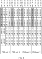
- FIG. 10 is a schematic diagram of an embodiment of eREGs that may be occupied by a distributed E-PDCCH according to the present invention.
- the 4 PRB pairs respectively correspond to VRB pairs 0-3.
- there are b 4 eCCEs, but only two may be used to transmit the distributed E-PDCCH, and the two eCCEs are numbered 0 and 1 respectively.
- physical resource elements occupied by different eCCEs in a PRB pair are predefined; and physical resource elements occupied by different eREGs and different eREG groups in an eCCE in a PRB pair are predefined.
- an eREG group includes 1 eREG, numbers of eREG groups in an eCCE are 0-3, and when an eREG group includes 2 eREGs, numbers of eREG groups in an eCCE are 0-1, and so on.
- FIG. 10 uses an example where an eREG group includes 1 eREG and numbers of eREG groups in an eCCE are 0-3.
- the shadow part in FIG. 10 indicates eREGs that the distributed E-PDCCH is allowed to use.
- an index of an eREG group may be expressed as (i, j, k), where, i indicates sequence numbers of RB pairs (for example, PRB pairs or VRB pairs), and the sequence numbers of the VRB pairs are used in this example; j indicates sequence numbers of eCCEs in an RB pair (for example, an PRB pair or a VRB pair); and k indicates a sequence number of an eREG group in an eCCE of an RB pair (for example, a PRB pair or a VRB pair).
- the mapping rule of M control channel candidates at the aggregation level L is: starting from a preset start position, mapping the M control channel candidates according to the sequence of first j, then i, and finally k.
- an index of the first eREG group or eREG in 8 eREG groups or eREGs of the first control channel candidate is (0, 0, 0); according to the sequence of first j, then i, and finally k, an index of the second eREG group or eREG is (0, 1, 0); an index of the third eREG group or eREG is (1, 0, 0); by analogy, an index of the eighth eREG group or eREG is (3, 1, 0).
- FIG. 11 is a schematic diagram of another embodiment of eREGs to which a distributed E-PDCCH is mapped according to the present invention.
- FIG. 11 indicates eREGs to which the first control channel candidate is mapped; indicates eREGs to which the second control channel candidate is mapped; and indicates eREGs to which the third control channel candidate is mapped.
- FIG. 12 is a flowchart of an embodiment of a method for receiving a control channel according to the present invention. As shown in FIG. 12 , the method for receiving a control channel may include: Step 1201: Determine m PRB pairs used for transmitting a control channel.
- An i th PRB pair includes n i first physical resource elements, the i th physical resource block pair includes k i second physical resource elements, and the second physical resource elements included in the m PRB pairs form multiple second physical resource element groups, where the first physical resource elements are used for transmitting the control channel to be transmitted by using a localized transmission mode, and the second physical resource elements are used for transmitting the control channel to be transmitted by using a distributed transmission mode, where m ⁇ 1, n i ⁇ 1, k i ⁇ 1, 0 ⁇ i ⁇ m-1, and m, i, n i , and k i are all integers.
- One of the first physical resource elements includes at least two second physical resource elements, that is, physical resources of the first physical resource element include physical resources of at least two second physical resource elements.
- the control channel may be an E-PDCCH or a PDCCH, which is not limited by this embodiment.
- Step 1202 Determine, according to an aggregation level L of the control channel, the number G L of second physical resource elements included in each of the second physical resource element groups, where the G L second physical resource elements included in each of the second physical resource element groups are located in ⁇ G L / q ⁇ first physical resource elements in the m PRB pairs, where q indicates the number of second physical resource elements included in one first physical resource element, ⁇ G L / q ⁇ indicates roundup of G L / q, G L ⁇ 1, L ⁇ 1, and G L and L are both integers.
- Step 1203 Determine, according to the aggregation level L, M control channel candidates at the aggregation level L.
- Each control channel candidate corresponds to N L second physical resource elements, where M ⁇ 1, N L ⁇ 1, and M and N L are both integers.
- Step 1204 Detect the M control channel candidates.
- the G L second physical resource elements are located in one first physical resource element in the m PRB pairs.
- the determining, according to an aggregation level L of the control channel, the number G L of second physical resource elements included in each of the second physical resource element groups may be: obtaining the number G L configured by higher layer signaling and corresponding to the aggregation level L, of second physical resource elements included in each of the second physical resource element groups; or determining the G L according to a preset mapping relationship between the aggregation level L and the number G L of second physical resource elements included in each of the second physical resource element groups.
- the number G L of second physical resource elements included in a second physical resource element group corresponding to at least one aggregation level is greater than or equal to 2; in this case, the number G L of second physical resource elements included in a second physical resource element group corresponding to at least one aggregation level is greater than or equal to 2, and the G L second physical resource elements included in each of the second physical resource element groups are located in ⁇ G L / q ⁇ first physical resource elements in the m PRB pairs, and therefore, at this aggregation level, each of the second physical resource element groups occupies fewer first physical resource elements, thereby avoiding a case where each second physical resource element in the second physical resource element group occupies one first physical resource element, so that more first physical resource elements may be used in the localized transmission mode; or for at least two aggregation levels in multiple different aggregation levels, a second physical resource element group corresponding to a higher aggregation level in the at least two aggregation levels includes more second
- a performance gain is not great.
- correlation also exists in a frequency domain, and only a limited diversity gain can be obtained in the frequency domain. Therefore, it is unnecessary to distribute the second physical resource elements occupied by the control channel at the higher aggregation level to a lot of PRB pairs, so long as a certain diversity gain is obtained.
- the second physical resource elements occupied by the control channel at the higher aggregation level are distributed to 4 channel-independent PRB pairs in 4 frequency domains. Therefore, in the case where a certain frequency diversity gain is obtained at each aggregation level, some first physical resource elements are reserved for a localized E-PDCCH.
- all second physical resource elements included in one second physical resource element group are located in one PRB pair; or all second physical resource elements included in all the second physical resource element groups are located on physical resources of a part of first physical resource elements in the m PRB pairs; or in one PRB pair, all second physical resource elements included in one second physical resource element group are located on physical resources of a part of first physical resource elements in the one PRB pair; or in one PRB pair, all second physical resource elements included in all second physical resource element groups are located on physical resources of a part of first physical resource elements in the one PRB pair. Therefore, some first physical resource elements may be used for localized E-PDCCH transmission.
- all second physical resource element groups are formed by physical resources corresponding to a part of antenna ports in the one PRB pair; or in one PRB pair, all second physical resource elements included in all second physical resource element groups are located in first physical resource elements corresponding to a part of antenna ports in the one PRB pair.
- the detecting the M control channel candidates may be: detecting physical resources to which the M control channel candidates are mapped, and when a correct control channel is detected, parsing the correct control channel to obtain control information borne in the correct control channel, or when no correct control channel is detected, continuing to perform the step of determining the number M of control channel candidates at other aggregation levels than the aggregation level L and subsequent steps, until a correct control channel is detected or until all control channel candidates corresponding to all aggregation levels are traversed.
- the determining, according to the aggregation level L, M control channel candidates at the aggregation level L may be: determining, according to the aggregation level L, the number M of control channel candidates at the aggregation level L, where M is an integer, and M ⁇ 1; and determining a mapping from the M control channel candidates to physical resources in the m PRB pairs.
- the determining that the M control channel candidates are mapped to M ⁇ H L virtual resource elements in a virtual resource element set may be: determining that the M control channel candidates are mapped to M ⁇ H L consecutive virtual resource elements starting from a pre-obtained start position.
- the sequence numbers of the RB pairs are sequence numbers of PRB pairs or sequence numbers of VRB pairs; and when the sequence numbers of the RB pairs are sequence numbers of VRB pairs, a mapping relationship exists between the sequence numbers of the VRB pairs and the sequence numbers of the PRB pairs.
- any control channel candidate of a distributed control channel to be transmitted is mapped to physical resources, and some eREGs of the control channel candidate are mapped to a PRB pair, these eREGs are preferably mapped to physical resources corresponding to fewest localized eCCEs in the PRB pair, thereby improving multiplexing efficiency of control channels of different modes.
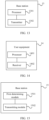
- FIG. 13 is a schematic structural diagram of an embodiment of a base station according to the present invention.
- a base station 13 in this embodiment may implement the procedure of the embodiment shown in FIG. 1 of the present invention.
- the base station 13 may include: a processor 1301 and a transmitter 1302.
- the processor 1301 is configured to: determine m PRB pairs used for transmitting a control channel to be transmitted, where an i th PRB pair includes n i first physical resource elements, the i th PRB pair includes k i second physical resource elements, and the second physical resource elements included in the m PRB pairs form multiple second physical resource element groups, where the first physical resource elements are used for transmitting the control channel to be transmitted by using a localized transmission mode, the second physical resource elements are used for transmitting the control channel to be transmitted by using a distributed transmission mode, and one of the first physical resource elements includes at least two second physical resource elements, where m ⁇ 1, n i ⁇ 1, k i ⁇ 1, 0 ⁇ i ⁇ m-1, and m, i, n i , and k i are all integers; when the control channel to be transmitted is transmitted by using the distributed transmission mode, determine an aggregation level L of the control channel to be transmitted, where L ⁇ 1, and L is an integer; determine, according to
- the transmitter 1302 is configured to place, on physical resources to which the first control channel candidate is mapped, control information of the control channel to be transmitted, and transmit the control information.
- the control channel may be an E-PDCCH or a PDCCH, which is not limited by this embodiment.
- the G L second physical resource elements are located in one first physical resource element in the m PRB pairs.
- the processor 1301 being configured to determine, according to the aggregation level L, the number G L of second physical resource elements included in each of the second physical resource element groups may be: the processor 1301 being configured to determine the G L according to a preset mapping relationship between the aggregation level L and the number G L of second physical resource elements included in each of the second physical resource element groups.
- the transmitter 1302 is further configured to transmit higher layer signaling to a receiving device, where the higher layer signaling is used for configuring the number G L corresponding to the aggregation level L, of second physical resource elements included in each of the second physical resource element groups.
- the number G L of second physical resource elements included in a second physical resource element group corresponding to at least one aggregation level is greater than or equal to 2; in this case, the number G L of second physical resource elements included in a second physical resource element group corresponding to at least one aggregation level is greater than or equal to 2, and the G L second physical resource elements included in each of the second physical resource element groups are located in ⁇ G L / q ⁇ first physical resource elements in the m PRB pairs, and therefore, at this aggregation level, each of the second physical resource element groups occupies fewer first physical resource elements, thereby avoiding a case where each second physical resource element in the second physical resource element group occupies one first physical resource element, so that more first physical resource elements may be used in the localized transmission mode; or for at least two aggregation levels in multiple different aggregation levels, a second physical resource element group corresponding to a higher aggregation level in the at least two aggregation levels includes more second
- a performance gain is not great.
- correlation also exists in a frequency domain, and only a limited diversity gain can be obtained in the frequency domain. Therefore, it is unnecessary to distribute the second physical resource elements occupied by the control channel at the higher aggregation level to a lot of PRB pairs, so long as a certain diversity gain is obtained.
- the second physical resource elements occupied by the control channel at the higher aggregation level are distributed to 4 channel-independent PRB pairs in 4 frequency domains. Therefore, in the case where a certain frequency diversity gain is obtained at each aggregation level, some first physical resource elements are reserved for a localized E-PDCCH.
- all second physical resource elements included in one second physical resource element group are located in one PRB pair; or all second physical resource elements included in all the second physical resource element groups are located on physical resources of a part of first physical resource elements in the m physical resource block pairs; or in one PRB pair, all second physical resource elements included in one second physical resource element group are located on physical resources of a part of first physical resource elements in the one PRB pair; or in one PRB pair, all second physical resource elements included in all second physical resource element groups are located on physical resources of a part of first physical resource elements in the one PRB pair. Therefore, some first physical resource elements may be used for localized E-PDCCH transmission.
- all second physical resource element groups are formed by physical resources corresponding to a part of antenna ports in the one PRB pair; or in one PRB pair, all second physical resource elements included in all second physical resource element groups are located in first physical resource elements corresponding to a part of antenna ports in the one PRB pair.
- the processor 1301 being configured to determine, according to the aggregation level L, a first control channel candidate at the aggregation level L may be: the processor 1301 being configured to determine, according to the aggregation level L, the number M of control channel candidates at the aggregation level L, where M is an integer, and M ⁇ 1; map the M control channel candidates to physical resources in the m PRB pairs; and select one first control channel candidate from the M control channel candidates.
- the processor 1301 being configured to map the M control channel candidates to M ⁇ H L virtual resource elements in the virtual resource element set may be: the processor 1301 being configured to map, according to a pre-obtained start position, the M control channel candidates to M ⁇ H L consecutive virtual resource elements consecutively.
- the sequence numbers of the RB pairs are sequence numbers of PRB pairs or sequence numbers of virtual resource block pairs; and when the sequence numbers of the RB pairs are sequence numbers of virtual resource block pairs, a mapping relationship exists between the sequence numbers of the virtual resource block pairs and the sequence numbers of the PRB pairs.
- any control channel candidate of a distributed control channel to be transmitted is mapped to physical resources, and some eREGs of the control channel candidate are mapped to a PRB pair, these eREGs are preferably mapped to physical resources corresponding to fewest localized eCCEs in the PRB pair, thereby improving multiplexing efficiency of control channels of different modes.
- FIG. 14 is a schematic structural diagram of an embodiment of a user equipment according to the present invention.
- a user equipment 14 in this embodiment may implement the procedure of the embodiment shown in FIG. 12 of the present invention.
- the user equipment 14 may include: a processor 1401 and a receiver 1402.
- the processor 1401 is configured to: determine m PRB pairs used for transmitting a control channel, where an i th PRB pair includes n i first physical resource elements, the i th PRB pair includes k i second physical resource elements, and the second physical resource elements included in the m PRB pairs form multiple second physical resource element groups, where the first physical resource elements are used for transmitting the control channel to be transmitted by using a localized transmission mode, the second physical resource elements are used for transmitting the control channel to be transmitted by using a distributed transmission mode, and one of the first physical resource elements includes at least two second physical resource elements, where m ⁇ 1, n i ⁇ 1, k i ⁇ 1, 0 ⁇ i ⁇ m-1, and m, i, n i , and k i are all integers; determine, according to an aggregation level L of the control channel, the number G L of second physical resource elements included in each of the second physical resource element groups, where the G L second physical resource elements included in each of the second
- the receiver 1402 is configured to detect the M control channel candidates.
- the control channel may be an E-PDCCH or a PDCCH, which is not limited by this embodiment.
- the G L second physical resource elements are located in one first physical resource element in the m PRB pairs.
- the processor 1401 being configured to determine, according to an aggregation level L of the control channel, the number G L of second physical resource elements included in each of the second physical resource element groups may be: the processor 1401 being configured to: obtain the number G L configured by higher layer signaling and corresponding to the aggregation level L, of second physical resource elements included in each of the second physical resource element groups; or determine the G L according to a preset mapping relationship between the aggregation level L and the number G L of second physical resource elements included in each of the second physical resource element groups.
- the number G L of second physical resource elements included in a second physical resource element group corresponding to at least one aggregation level is greater than or equal to 2; in this case, the number G L of second physical resource elements included in a second physical resource element group corresponding to at least one aggregation level is greater than or equal to 2, and the G L second physical resource elements included in each of the second physical resource element groups are located in ⁇ G L / q ⁇ first physical resource elements in the m PRB pairs, and therefore, at this aggregation level, each of the second physical resource element groups occupies fewer first physical resource elements, thereby avoiding a case where each second physical resource element in the second physical resource element group occupies one first physical resource element, so that more first physical resource elements may be used in the localized transmission mode; or for at least two aggregation levels in multiple different aggregation levels, a second physical resource element group corresponding to a higher aggregation level in the at least two aggregation levels includes more second
- a performance gain is not great.
- correlation also exists in a frequency domain, and only a limited diversity gain can be obtained in the frequency domain. Therefore, it is unnecessary to distribute the second physical resource elements occupied by the control channel at the higher aggregation level to a lot of PRB pairs, so long as a certain diversity gain is obtained.
- the second physical resource elements occupied by the control channel at the higher aggregation level are distributed to 4 channel-independent PRB pairs in 4 frequency domains. Therefore, in the case where a certain frequency diversity gain is obtained at each aggregation level, some first physical resource elements are reserved for a localized E-PDCCH.
- all second physical resource elements included in one second physical resource element group are located in one PRB pair; or all second physical resource elements included in all the second physical resource element groups are located on physical resources of a part of first physical resource elements in the m PRB pairs; or in one PRB pair, all second physical resource elements included in one second physical resource element group are located on physical resources of a part of first physical resource elements in the one PRB pair; or in one PRB pair, all second physical resource elements included in all second physical resource element groups are located on physical resources of a part of first physical resource elements in the one PRB pair. Therefore, some first physical resource elements may be used for localized E-PDCCH transmission.
- all second physical resource element groups are formed by physical resources corresponding to a part of antenna ports in the one PRB pair; or in one PRB pair, all second physical resource elements included in all second physical resource element groups are located in first physical resource elements corresponding to a part of antenna ports in the one PRB pair.
- the receiver 1402 being configured to detect the M control channel candidates may be: the receiver 1402 being configured to detect physical resources to which the M control channel candidates are mapped, and when a correct control channel is detected, parse the correct control channel to obtain control information borne in the correct control channel, or when no correct control channel is detected, continue to perform the step of determining the number M of control channel candidates at other aggregation levels than the aggregation level L and subsequent steps, until a correct control channel is detected or until all control channel candidates corresponding to all aggregation levels are traversed.
- the processor 1401 being configured to determine, according to the aggregation level L, M control channel candidates at the aggregation level L may be: the processor 1401 being configured to: determine, according to the aggregation level L, the number M of control channel candidates at the aggregation level L, where M is an integer, and M ⁇ 1; and determine a mapping from the M control channel candidates to physical resources in the m PRB pairs.
- the processor 1401 being configured to determine that the M control channel candidates are mapped to M ⁇ H L virtual resource elements in a virtual resource element set may be: the processor 1401 being configured to determine that the M control channel candidates are mapped to M ⁇ H L consecutive virtual resource elements starting from a pre-obtained start position.
- the sequence numbers of the RB pairs are sequence numbers of PRB pairs or sequence numbers of VRB pairs; and when the sequence numbers of the RB pairs are sequence numbers of VRB pairs, a mapping relationship exists between the sequence numbers of the VRB pairs and the sequence numbers of the PRB pairs.
- any control channel candidate of a distributed control channel to be transmitted is mapped to physical resources, and some eREGs of the control channel candidate are mapped to a PRB pair, these eREGs are preferably mapped to physical resources corresponding to fewest localized eCCEs in the PRB pair, thereby improving multiplexing efficiency of control channels of different modes.
- FIG. 15 is a schematic structural diagram of another embodiment of a base station according to the present invention.
- a base station 15 in this embodiment may implement the procedure of the embodiment shown in FIG. 1 of the present invention.
- the base station 15 may include: a first determining module 1501 and a transmitting module 1502.
- the first determining module 1501 is configured to: determine m PRB pairs used for transmitting a control channel to be transmitted, where an i th PRB pair includes n i first physical resource elements, the i th PRB pair includes k i second physical resource elements, and the second physical resource elements included in the m PRB pairs form multiple second physical resource element groups, where the first physical resource elements are used for transmitting the control channel to be transmitted by using a localized transmission mode, the second physical resource elements are used for transmitting the control channel to be transmitted by using a distributed transmission mode, and one of the first physical resource elements includes at least two second physical resource elements, where m ⁇ 1, n i ⁇ 1, k i ⁇ 1, 0 ⁇ i ⁇ m-1, and m, i, n i , and k i are all integers; when the control channel to be transmitted is transmitted by using the distributed transmission mode, determine an aggregation level L of the control channel to be transmitted, where L ⁇ 1, and L is an integer; determine
- the transmitting module 1502 is configured to: receive, from the first determining module 1501, the physical resources to which the first control channel candidate is mapped; and place, on the physical resources to which the first control channel candidate is mapped, control information of the control channel to be transmitted, and transmit the control information.
- the control channel may be an E-PDCCH or a PDCCH, which is not limited by this embodiment.
- the G L second physical resource elements are located in one first physical resource element in the m PRB pairs.
- the first determining module 1501 being configured to determine, according to the aggregation level L, the number G L of second physical resource elements included in each of the second physical resource element groups may be: the first determining module 1501 being configured to determine the G L according to a preset mapping relationship between the aggregation level L and the number G L of second physical resource elements included in each of the second physical resource element groups.
- the transmitting module 1502 is further configured to transmit higher layer signaling to a receiving device, where the higher layer signaling is used for configuring the number G L corresponding to the aggregation level L, of second physical resource elements included in each of the second physical resource element groups.
- the number G L of second physical resource elements included in a second physical resource element group corresponding to at least one aggregation level is greater than or equal to 2; in this case, the number G L of second physical resource elements included in a second physical resource element group corresponding to at least one aggregation level is greater than or equal to 2, and the G L second physical resource elements included in each of the second physical resource element groups are located in ⁇ G L / q ⁇ first physical resource elements in the m PRB pairs, and therefore, at this aggregation level, each of the second physical resource element groups occupies fewer first physical resource elements, thereby avoiding a case where each second physical resource element in the second physical resource element group occupies one first physical resource element, so that more first physical resource elements may be used in the localized transmission mode; or for at least two aggregation levels in multiple different aggregation levels, a second physical resource element group corresponding to a higher aggregation level in the at least two aggregation levels includes more second
- a performance gain is not great.
- correlation also exists in a frequency domain, and only a limited diversity gain can be obtained in the frequency domain. Therefore, it is unnecessary to distribute the second physical resource elements occupied by the control channel at the higher aggregation level to a lot of PRB pairs, so long as a certain diversity gain is obtained.
- the second physical resource elements occupied by the control channel at the higher aggregation level are distributed to 4 channel-independent PRB pairs in 4 frequency domains. Therefore, in the case where a certain frequency diversity gain is obtained at each aggregation level, some first physical resource elements are reserved for a localized E-PDCCH.
- all second physical resource elements included in one second physical resource element group are located in one PRB pair; or all second physical resource elements included in all the second physical resource element groups are located on physical resources of a part of first physical resource elements in the m PRB pairs; or in one PRB pair, all second physical resource elements included in one second physical resource element group are located on physical resources of a part of first physical resource elements in the one PRB pair; or in one PRB pair, all second physical resource elements included in all second physical resource element groups are located on physical resources of a part of first physical resource elements in the one PRB pair. Therefore, some first physical resource elements may be used for localized E-PDCCH transmission.
- all second physical resource element groups are formed by physical resources corresponding to a part of antenna ports in the one PRB pair; or in one PRB pair, all second physical resource elements included in all second physical resource element groups are located in first physical resource elements corresponding to a part of antenna ports in the one PRB pair.
- the first determining module 1501 being configured to determine, according to the aggregation level L, a first control channel candidate at the aggregation level L may be: the first determining module 1501 being configured to determine, according to the aggregation level L, the number M of control channel candidates at the aggregation level L, where M is an integer, and M ⁇ 1, map the M control channel candidates to physical resources in the m PRB pairs, and select one first control channel candidate from the M control channel candidates.
- the first determining module 1501 being configured to map the M control channel candidates to M ⁇ H L virtual resource elements in the virtual resource element set may be: the first determining module 1501 being configured to map, according to a pre-obtained start position, the M control channel candidates to M ⁇ H L consecutive virtual resource elements consecutively.
- the sequence numbers of the RB pairs are sequence numbers of PRB pairs or sequence numbers of virtual resource block pairs; and when the sequence numbers of the RB pairs are sequence numbers of virtual resource block pairs, a mapping relationship exists between the sequence numbers of the virtual resource block pairs and the sequence numbers of the PRB pairs.
- any control channel candidate of a distributed control channel to be transmitted is mapped to physical resources, and some eREGs of the control channel candidate are mapped to a PRB pair, these eREGs are preferably mapped to physical resources corresponding to fewest localized eCCEs in the PRB pair, thereby improving multiplexing efficiency of control channels of different modes.
- FIG. 16 is a schematic structural diagram of another embodiment of a user equipment according to the present invention.
- a user equipment 16 in this embodiment may implement the procedure of the embodiment shown in FIG. 12 of the present invention.
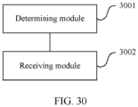
- the user equipment 16 may include: a second determining module 1601 and a receiving module 1602.
- the second determining module 1601 is configured to: determine m PRB pairs used for transmitting a control channel, where an i th PRB pair includes n i first physical resource elements, the i th PRB pair includes k i second physical resource elements, and the second physical resource elements included in the m PRB pairs form multiple second physical resource element groups, where the first physical resource elements are used for transmitting the control channel to be transmitted by using a localized transmission mode, the second physical resource elements are used for transmitting the control channel to be transmitted by using a distributed transmission mode, and one of the first physical resource elements includes at least two second physical resource elements, where m ⁇ 1, n i ⁇ 1, k i ⁇ 1, 0 ⁇ i ⁇ m-1, and m, i, n i , and k i are all integers; determine, according to an aggregation level L of the control channel, the number G L of second physical resource elements included in each of the second physical resource element groups, where the G L second physical resource elements included in each
- the receiving module 1602 is configured to detect the M control channel candidates determined by the determining module 1601.
- the control channel may be an E-PDCCH or a PDCCH, which is not limited by this embodiment.
- the G L second physical resource elements are located in one first physical resource element in the m PRB pairs.
- the second determining module 1601 being configured to determine, according to an aggregation level L of the control channel, the number G L of second physical resource elements included in each of the second physical resource element groups may be: the second determining module 1601 being configured to: obtain the number G L configured by higher layer signaling and corresponding to the aggregation level L, of second physical resource elements included in each of the second physical resource element groups; or determine the G L according to a preset mapping relationship between the aggregation level L and the number G L of second physical resource elements included in each of the second physical resource element groups.
- the number G L of second physical resource elements included in a second physical resource element group corresponding to at least one aggregation level is greater than or equal to 2; in this case, the number G L of second physical resource elements included in a second physical resource element group corresponding to at least one aggregation level is greater than or equal to 2, and the G L second physical resource elements included in each of the second physical resource element groups are located in ⁇ G L / q ⁇ first physical resource elements in the m PRB pairs, and therefore, at this aggregation level, each of the second physical resource element groups occupies fewer first physical resource elements, thereby avoiding a case where each second physical resource element in the second physical resource element group occupies one first physical resource element, so that more first physical resource elements may be used in the localized transmission mode; or for at least two aggregation levels in multiple different aggregation levels, a second physical resource element group corresponding to a higher aggregation level in the at least two aggregation levels includes more second
- a performance gain is not great.
- correlation also exists in a frequency domain, and only a limited diversity gain can be obtained in the frequency domain. Therefore, it is unnecessary to distribute the second physical resource elements occupied by the control channel at the higher aggregation level to a lot of PRB pairs, so long as a certain diversity gain is obtained.
- the second physical resource elements occupied by the control channel at the higher aggregation level are distributed to 4 channel-independent PRB pairs in 4 frequency domains. Therefore, in the case where a certain frequency diversity gain is obtained at each aggregation level, some first physical resource elements are reserved for a localized E-PDCCH.
- all second physical resource elements included in one second physical resource element group are located in one PRB pair; or all second physical resource elements included in all the second physical resource element groups are located on physical resources of a part of first physical resource elements in the m physical resource block pairs; or in one PRB pair, all second physical resource elements included in one second physical resource element group are located on physical resources of a part of first physical resource elements in the one PRB pair; or in one PRB pair, all second physical resource elements included in all second physical resource element groups are located on physical resources of a part of first physical resource elements in the one PRB pair. Therefore, some first physical resource elements may be used for localized E-PDCCH transmission.
- all second physical resource element groups are formed by physical resources corresponding to a part of antenna ports in the one PRB pair; or in one PRB pair, all second physical resource elements included in all second physical resource element groups are located in first physical resource elements corresponding to a part of antenna ports in the one PRB pair.
- the receiving module 1602 being configured to detect the M control channel candidates determined by the second determining module 1601 may be: the receiving module 1602 being configured to detect physical resources to which the M control channel candidates are mapped, and when a correct control channel is detected, parse the correct control channel to obtain control information borne in the correct control channel, or when no correct control channel is detected, continue to perform the step of determining the number M of control channel candidates at other aggregation levels than the aggregation level L and subsequent steps, until a correct control channel is detected or until all control channel candidates corresponding to all aggregation levels are traversed.
- the second determining module 1601 being configured to determine, according to the aggregation level L, M control channel candidates at the aggregation level L may be: the second determining module 1601 being configured to: determine, according to the aggregation level L, the number M of control channel candidates at the aggregation level L, where M is an integer, and M ⁇ 1; and determine a mapping from the M control channel candidates to physical resources in the m PRB pairs.
- the second determining module 1601 being configured to determine that the M control channel candidates are mapped to M ⁇ H L virtual resource elements in a virtual resource element set may be: the second determining module 1601 being configured to determine that the M control channel candidates are mapped to M ⁇ H L consecutive virtual resource elements starting from a pre-obtained start position.
- the sequence numbers of the RB pairs are sequence numbers of PRB pairs or sequence numbers of VRB pairs; and when the sequence numbers of the RB pairs are sequence numbers of VRB pairs, a mapping relationship exists between the sequence numbers of the VRB pairs and the sequence numbers of the PRB pairs.
- any control channel candidate of a distributed control channel to be transmitted is mapped to physical resources, and some eREGs of the control channel candidate are mapped to a PRB pair, these eREGs are preferably mapped to physical resources corresponding to fewest localized eCCEs in the PRB pair, thereby improving multiplexing efficiency of control channels of different modes.
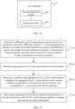
- FIG. 17 is a flowchart of another embodiment of a method for transmitting a control channel according to the present invention. As shown in FIG. 17 , the method for transmitting a control channel may include:
- the first physical resource elements when the first physical resource elements are used for transmitting the control channel to be transmitted by using a localized transmission mode, the first physical resource elements are localized first physical resource elements; when the first physical resource elements are used for transmitting the control channel to be transmitted by using a distributed transmission mode, the first physical resource elements are distributed first physical resource elements;
- a mapping relationship exists between numbers of second physical resource elements included in one localized first physical resource element in one PRB pair and numbers of second physical resource elements included in one distributed first physical resource element in the one PRB pair; and second physical resource elements included in one localized first physical resource element are located in one PRB pair, and second physical resource elements included in one distributed first physical resource element are located in at least two PRB pairs.
- numbers of second physical resource elements included in one localized first physical resource element in one PRB pair and numbers of second physical resource elements included in one distributed first physical resource element in the one PRB pair are the same.
- numbers of m ⁇ n distributed first physical resource elements in the m PRB pairs are respectively x, x+1, ..., x+m ⁇ n-1, and numbers of n localized first physical resource elements in each of the PRB pairs are respectively z, z+1, ..., z+n-1;
- each of the PRB pairs includes n sub-blocks, and each sub-block includes q second physical resource elements;
- the m PRB pairs include n sub-block groups, each sub-block group includes m sub-blocks, which are located in different PRB pairs, and numbers of the m ⁇ n first physical resource elements included in the m PRB pairs are respectively x, x+1, ..., x+m ⁇ n-1;
- each sub-block group includes m ⁇ q second physical resource elements; and numbers of m first physical resource elements in each of the sub-block groups are y, y+1, ..., y+m-1; and values of y are x, x+m, x+2m, ..., x+(n-1) ⁇ m.
- the number of PRB pairs to which each first physical resource element is mapped is uniformly A; and/or
- any control channel candidate consecutively occupies L distributed first physical resource elements, and the M control channel candidates occupy M ⁇ L consecutive distributed first physical resource elements.
- any control channel candidate of a distributed control channel to be transmitted is mapped to physical resources, and some eREGs of the control channel candidate are mapped to a PRB pair, these eREGs are preferably mapped to physical resources corresponding to fewest localized eCCEs in the PRB pair, thereby improving multiplexing efficiency of control channels of different modes.
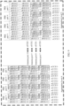
- FIG. 18 is a flowchart of another embodiment of a method for receiving a control channel according to the present invention. As shown in FIG. 18 , the method for receiving a control channel may include:
- the first physical resource elements when the first physical resource elements are used for transmitting the control channel to be transmitted by using a localized transmission mode, the first physical resource elements are localized first physical resource elements; when the first physical resource elements are used for transmitting the control channel to be transmitted by using a distributed transmission mode, the first physical resource elements are distributed first physical resource elements;
- a mapping relationship exists between numbers of second physical resource elements included in one localized first physical resource element in one PRB pair and numbers of second physical resource elements included in one distributed first physical resource element in the one PRB pair; and second physical resource elements included in one localized first physical resource element are located in one PRB pair, and second physical resource elements included in one distributed first physical resource element are located in at least two PRB pairs.
- numbers of second physical resource elements included in one localized first physical resource element in one PRB pair and numbers of second physical resource elements included in one distributed first physical resource element in the one PRB pair are the same.
- numbers of m ⁇ n distributed first physical resource elements in the m PRB pairs are respectively x, x+1, ..., x+m ⁇ n-1, and numbers of n localized first physical resource elements in each of the PRB pairs are respectively z, z+1, ..., z+n-1;
- each of the PRB pairs includes n sub-blocks, and each sub-block includes q second physical resource elements;
- the m PRB pairs include n sub-block groups, each sub-block group includes m sub-blocks, which are located in different PRB pairs, and numbers of the m ⁇ n first physical resource elements included in the m PRB pairs are respectively x, x+1, ..., x+m ⁇ n-1;
- each sub-block group includes m ⁇ q second physical resource elements; and numbers of m first physical resource elements in each of the sub-block groups are y, y+1, ..., y+m-1; and values of y are x, x+m, x+2m, ..., x+(n-1) ⁇ m.
- the number of PRB pairs to which each first physical resource element is mapped is uniformly A; and/or
- any control channel candidate consecutively occupies L distributed first physical resource elements, and the M control channel candidates occupy M ⁇ L consecutive distributed first physical resource elements.
- any control channel candidate of a distributed control channel to be transmitted is mapped to physical resources, and some eREGs of the control channel candidate are mapped to a PRB pair, these eREGs are preferably mapped to physical resources corresponding to fewest localized eCCEs in the PRB pair, thereby improving multiplexing efficiency of control channels of different modes.
- the first physical resource elements may be physical resources corresponding to eCCEs.
- the size of a first physical resource element corresponds to the size of an eCCE, that is, a physical resource element included in one of the first physical resource element may contain one eCCE.
- the second physical resource elements may be physical resources corresponding to eREGs.
- the size of a second physical resource element corresponds to the size of an eREG, or a second physical resource element itself is an eREG.
- control channel to be transmitted may be an E-PDCCH.
- One E-PDCCH may include at least one eCCE.
- At least one E-PDCCH set may be defined, and furthermore, in an E-PDCCH set, a group of m PRB pairs is defined.
- the value range of m is 1, 2, 4, 8, or 16.
- q 4 for a normal subframe (namely, a subframe including a normal cyclic prefix).
- PRB pair there are 16 eREGs. Because for a localized E-PDCCH, REs corresponding to an eCCE are located in a PRB pair, for the localized E-PDCCH, REs occupied by a PRB pair are equivalent to REs occupied by 4 eCCEs.
- an embodiment of the present invention describes the definition of a distributed eCCE in the case where the number m of PRB pairs in a set is 2, 4, 8, or 16, and the rule of mapping a distributed E-PDCCH to eREGs at different aggregation levels.
- FIG. 19 is a schematic diagram of an embodiment of a mapping of eREGs in a normal subframe according to the present invention.
- each column indicates an OFDM symbol, and there are 14 OFDM symbols in total, whose indexes are 0-13; each row indicates a subcarrier in a frequency domain, and there are 12 subcarriers in total, whose indexes are 0-11.
- an RE numbered x indicates that the RE belongs to an eREG numbered x. 4 eREGs form an eCCE.
- eREGs indexed 0, 4, 8, and 12 form an eCCE (eCCE0); eREGs indexed 1, 5, 9, and 13 form an eCCE (eCCE1); eREGs indexed 2, 6, 10, and 14 form an eCCE (eCCE2); and eREGs indexed 3, 7, 11, and 15 form an eCCE (eCCE3).
- Table 2 The details are shown in Table 2.
- 4 eREGs of a PRB pair form an eCCE; for the distributed E-PDCCH, 4 eREGs of an eCCE are distributed in at least two PRB pairs.
- the m PRB pairs are numbered PRB1, PRB2, ..., PRBm in ascending or descending order of sequence numbers of PRB pairs.
- an E-PDCCH set includes 4 PRB pairs, whose indexes are #1, #8, #10, and #15 respectively in system bandwidth. Therefore, the PRB pair indexed #1 may be described as PRB1; the PRB pair indexed #8 may be described as PRB2; the PRB pair indexed #10 may be described as PRB3; and the PRB pair indexed #15 may be described as PRB4.
- AL Aggregation Level
- the E-PDCCH set includes m PRB pairs.
- PRB pairs include 8 eCCEs, where the eREGs occupied by the 8 eCCEs are all mapped according to the foregoing rule, which is not further described herein.
- a potential E-PDCCH candidate occupies 8 eREGs, that is, eREGs in each row in FIG. 20 are eREGs occupied by a potential E-PDCCH candidate. That is, a potential E-PDCCH candidate occupies 2 distributed eCCEs.
- eREGs corresponding to a distributed eCCE are eREG0 of PRB pair 1, eREG4 of PRB pair 2, eREG8 of PRB pair 1, and eREG12 of PRB pair 2.
- eREGs corresponding to another distributed eCCE are eREG4 of PRB pair 1, eREG8 of PRB pair 2, eREG12 of PRB pair 1, and eREG0 of PRB pair 2.
- eREGs occupied by the potential E-PDCCH candidate, in each PRB pair are located in only one localized eCCE, which can ensure that fewest resources of localized eCCEs are occupied.
- eREGs occupied by a potential E-PDCCH candidate are formed by eREGs occupied by two potential E-PDCCH candidates at aggregation level 2 in FIG. 20 .
- eREGs corresponding to one E-PDCCH are located in 4 PRB pairs respectively.
- indexes of eREGs corresponding to an eCCE of a distributed E-PDCCH are the same as those corresponding to a localized eCCE, as shown in Table 2, but 4 eREGs included in an eCCE of a distributed E-PDCCH are distributed in 4 PRB pairs.
- eREG0 of PRB pair 1, eREG4 of PRB pair 2, eREG8 of PRB pair 3, and eREG12 of PRB pair 4 form an eCCE
- eREG4 of PRB pair 1, eREG8 of PRB pair 2, eREG12 of PRB pair 3, and eREG0 of PRB pair 4 form an eCCE
- eREG8 of PRB pair 1, eREG12 of PRB pair 2, eREG0 of PRB pair 3, and eREG4 of PRB pair 4 form an eCCE
- eREG12 of PRB pair 1, eREG0 of PRB pair 2, eREG4 of PRB pair 3, and eREG8 of PRB pair 4 form an eCCE.
- an eCCE formed by eREGs indexed 1, 5, 9, and 13 an eCCE formed by eREGs indexed 2, 6, 10, and 13, and an eCCE formed by eREGs indexed 3, 7, 11, and 15 may be obtained.
- each PRB pair includes 2 eREGs, and the 2 eREGs are located in a localized eCCE.
- a potential candidate at aggregation level 2 is formed by two distributed eCCEs, where one distributed eCCE is formed by eREG0 of PRB pair 1, eREG4 of PRB pair 2, eREG8 of PRB pair 3, and eREG12 of PRB pair 4, and another distributed eCCE is formed by eREG4 of PRB pair 1, eREG8 of PRB pair 2, eREG12 of PRB pair 3, and eREG0 of PRB pair 4.
- another potential candidate at aggregation level 2 is formed by two distributed eCCEs, where one distributed eCCE is formed by eREG8 of PRB pair 1, eREG12 of PRB pair 2, eREG0 of PRB pair 3, and eREG4 of PRB pair 4, and another distributed eCCE is formed by eREG12 of PRB pair 1, eREG0 of PRB pair 2, eREG4 of PRB pair 3, and eREG8 of PRB pair 4.
- a combination of potential candidates at aggregation level 2 which are formed by eREGs indexed 1, 5, 9, and 13 a combination of potential candidates at aggregation level 2 which are formed by eREGs indexed 2, 6, 10, and 13, and a combination of potential candidates at aggregation level 2 which are formed by eREGs indexed 3, 7, 11, and 15 may be obtained, which is not further described herein.
- a potential candidate at aggregation level 4 is formed by 4 distributed eCCEs, where one distributed eCCE is formed by eREG0 of PRB pair 1, eREG4 of PRB pair 2, eREG8 of PRB pair 3, and eREG12 of PRB pair 4; another distributed eCCE is formed by eREG4 of PRB pair 1, eREG8 of PRB pair 2, eREG12 of PRB pair 3, and eREG0 of PRB pair 4; another distributed eCCE is formed by eREG8 of PRB pair 1, eREG12 of PRB pair 2, eREG0 of PRB pair 3, and eREG4 of PRB pair 4; the last distributed eCCE is formed by eREG12 of PRB pair 1, eREG0 of PRB pair 2, eREG4 of PRB pair 3, and eREG8 of PRB pair 4.
- a potential E-PDCCH candidate at aggregation level 4 is placed in 4 PRB pairs. In each
- eREGs corresponding to a potential E-PDCCH candidate are formed by eREGs corresponding to two potential E-PDCCH candidates at aggregation level 4, which can ensure that fewest resources of localized eCCEs are occupied.
- eREGs corresponding to a potential E-PDCCH candidate are located in 4 PRB pairs respectively.
- indexes of eREGs corresponding to an eCCE of a distributed E-PDCCH are the same as those corresponding to a localized eCCE, as shown in Table 2, but 4 eREGs included in an eCCE of a distributed E-PDCCH are distributed in 4 PRB pairs.
- Table 3 shows positions of distributed eCCEs formed by eREGs indexed 0, 4, 8, and 12 in PRB pairs.
- Table 3 Distributed eCCE PRB Pair 1 PRB Pair 2 PRB Pair 3 PRB Pair 4 PRB Pair 5 PRB Pair 6 PRB Pair 7 PRB Pair 8 eCCE0 eREG0 eREG4 eREG8 eREG1 2 eCCE1 eREG4 eREG8 eREG12 eREG0 eCCE2 eREG8 eREG12 eREG0 eREG4 eCCE3 eREG12 eREG0 eREG4 eREG8 eCCE4 eREG 0 eREG4 eREG8 eREG1 2 eCCE5 eREG 4 eREG8 eREG12 eREG0 eCCE6 eREG 8 eREG12 eREG0 eREG4 eCCE
- eREG0 of an eCCE is eREG0 of PRB pair 1
- eREG4 is eREG4 of PRB pair 3
- eREG8 is eREG8 of PRB pair 5
- eREG12 is eREG12 of PRB pair 7.
- an eCCE formed by eREGs indexed 1, 5, 9, and 13 is obtained by replacing eREG0 with eREG1, eREG4 with eREG5, eREG8 with eREG9, and eREG12 with eREG13.
- an eCCE formed by eREGs indexed 2, 6, 10, and 13, and an eCCE formed by eREGs indexed 3, 7, 11, and 15 may be obtained.
- 8 eREGs corresponding to a potential E-PDCCH candidate are located in 8 PRB pairs, and each PRB pair includes an eREG.
- Indexes of the 8 eREGs include only 4 values, which are one of: 0, 4, 8, 16; 1, 5, 9, 13; 2, 6, 10, 13; and 3, 7, 11, 15.
- Table 4 shows potential candidates at aggregation level 2 which are formed by eREGs indexed 0, 4, 8, and 12.
- potential candidates at aggregation level 2 which are formed by eREGs indexed 1, 5, 9, and 13 are obtained by replacing eREG0 with eREG1, eREG4 with eREG5, eREG8 with eREG9, and eREG12 with eREG13.
- potential candidates at aggregation level 2 which are formed by eREGs indexed 2, 6, 10, and 13, and potential candidates at aggregation level 2 which are formed by eREGs indexed 3, 7, 11, and 15 may be obtained.
- 16 eREGs corresponding to a potential E-PDCCH candidate are located in 8 PRB pairs, and each PRB pair includes 2 eREGs.
- Indexes of the 8 eREGs include only 4 values, which are one of: 0, 4, 8, 16; 1, 5, 9, 13; 2, 6, 10, 13; and 3, 7, 11, 15.
- Table 5 shows potential candidates at aggregation level 4 which are formed by eREGs indexed 0, 4, 8, and 12.
- potential candidates at aggregation level 4 which are formed by eREGs indexed 1, 5, 9, and 13 are obtained by replacing eREG0 with eREG1, eREG4 with eREG5, eREG8 with eREG9, and eREG12 with eREG13.
- potential candidates at aggregation level 4 which are formed by eREGs indexed 2, 6, 10, and 13, and potential candidates at aggregation level 4 which are formed by eREGs indexed 3, 7, 11, and 15 may be obtained.
- each PRB pair includes 4 eREGs, and the 4 eREGs belong to a localized eCCE.
- indexes of the 8 eREGs include only 4 values.
- the 4 indexes are one of: 0, 4, 8, 16; 1, 5, 9, 13; 2, 6, 10, 13; and 3, 7, 11, 15.
- 4 eREGs form an eCCE.
- eCCE0 eCCE0
- eREGs indexed 1, 5, 9, and 13 form an eCCE (eCCE1)
- eREGs indexed 2, 6, 10, and 14 form an eCCE (eCCE2)
- eREGs indexed 3, 7, 11, and 15 form an eCCE (eCCE3), as shown in Table 2.
- FIG. 23 is a schematic diagram of another embodiment of an E-PDCCH set including 4 PRB pairs according to the present invention.
- FIG. 23 shows numbers of eREGs in a PRB pair, and shows numbers of eCCEs corresponding to eREGs.
- an eCCE numbered eCCE1 is formed by eREG4 of PRB pair 1, eREG8 of PRB pair 2, eREG12 of PRB pair 3, and eREG0 of PRB pair 4.
- FIG. 24 is a schematic diagram of an embodiment of distributed eCCEs occupied by control channel candidates at different aggregation levels according to the present invention.
- aggregation levels 1, 2, 4, and 8 respectively correspond to 6, 6, 2, and 2 candidates. If the start position at aggregation level 1 is eCCE1, 6 eCCEs are consecutively selected as 6 candidates, and the 6 candidates respectively correspond to eCCE1, eCCE2, eCCE3, eCCE4, eCCES, and eCCE6.
- the 6 candidates respectively correspond to: eCCE2, eCCE3; eCCE4, eCCE5; eCCE6, eCCE7; eCCE8, eCCE9; eCCE10, eCCE11; and eCCE12, eCCE13.
- the start position at aggregation level 4 is eCCE4
- the 2 candidates respectively correspond to: eCCE4, eCCE5, eCCE6, and eCCE7; and eCCE8, eCCE9, eCCE10, and eCCE11.
- the 2 candidates respectively correspond to eCCE8 to eCCE15, and eCCE0 to eCCE7. Thereby, it can be ensured that fewest resources of localized eCCEs are occupied.
- a position of a control channel candidate is drawn with respect to different aggregation levels.
- the shadow indicates a control channel candidate at aggregation level 1; the shadow
- indicates a control channel candidate at aggregation level 2; the shadow indicates a control channel candidate at aggregation level 4; and the shadow indicates a control channel candidate at aggregation level 8.
- a search space may be indicated by formula (1): L Y k + m ′ mod ⁇ N CCE ,k / L ⁇ + i
- a control channel includes a carrier indicator field (Carrier Indicator Field, CIF for short below)
- m' p' + M (L) ⁇ n CI , where, nci indicates a CIF value.
- N CCE,k indicates the number of eCCEs in a set.
- FIG. 25 is a schematic diagram of an embodiment of a numbering mode of eCCEs according to the present invention.
- FIG. 26 is a schematic diagram of another embodiment of a numbering mode of eCCEs according to the present invention.
- FIG. 27 is a schematic structural diagram of another embodiment of a base station according to the present invention.
- the base station in this embodiment may implement the procedure of the embodiment shown in FIG. 17 of the present invention.
- the base station may include: a processor 2701 and a transmitter 2702.
- the processor 2701 is configured to: determine m PRB pairs used for transmitting a control channel to be transmitted, where the m PRB pairs include m ⁇ n first physical resource elements, the number of resource elements occupied by each PRB pair is equal to the number of resource elements occupied by n first physical resource elements, and each of the first physical resource elements includes q second physical resource elements, where m ⁇ 1, n ⁇ 1, q ⁇ 2, and m, n, and q are all integers; determine an aggregation level L of the control channel to be transmitted, where L ⁇ 1, and L is an integer; and determine, according to the aggregation level L, a first control channel candidate at the aggregation level L, where the first control channel candidate corresponds to L first physical resource elements, and corresponds to L ⁇ q second physical resource elements.
- the transmitter 2702 is configured to place, on physical resources to which the first control channel candidate determined by the processor 2702 is mapped, control information of the control channel to be transmitted, and transmit the control information.
- the first physical resource elements when the first physical resource elements are used for transmitting the control channel to be transmitted by using a localized transmission mode, the first physical resource elements are localized first physical resource elements; when the first physical resource elements are used for transmitting the control channel to be transmitted by using a distributed transmission mode, the first physical resource elements are distributed first physical resource elements;
- a mapping relationship exists between numbers of second physical resource elements included in one localized first physical resource element in one PRB pair and numbers of second physical resource elements included in one distributed first physical resource element in the one PRB pair; and second physical resource elements included in one localized first physical resource element are located in one PRB pair, and second physical resource elements included in one distributed first physical resource element are located in at least two PRB pairs.
- numbers of second physical resource elements included in one localized first physical resource element in one PRB pair and numbers of second physical resource elements included in one distributed first physical resource element in the one PRB pair are the same.
- numbers of m ⁇ n distributed first physical resource elements in the m PRB pairs are respectively x, x+1, ..., x+m ⁇ n-1, and numbers of n localized first physical resource elements in each of the PRB pairs are respectively z, z+1, ..., z+n-1;
- each of the PRB pairs includes n sub-blocks, and each sub-block includes q second physical resource elements;
- the m PRB pairs include n sub-block groups, each sub-block group includes m sub-blocks, which are located in different PRB pairs, and numbers of the m ⁇ n first physical resource elements included in the m PRB pairs are respectively x, x+1, ..., x+m ⁇ n-1;
- each sub-block group includes m ⁇ q second physical resource elements; and numbers of m first physical resource elements in each of the sub-block groups are y, y+1, ..., y+m-1; and values of y are x, x+m, x+2m, ..., x+(n-1) ⁇ m.
- the number of PRB pairs to which each first physical resource element is mapped is uniformly A; and/or
- any control channel candidate consecutively occupies L distributed first physical resource elements, and the M control channel candidates occupy M ⁇ L consecutive distributed first physical resource elements.
- any control channel candidate of a distributed control channel to be transmitted is mapped to physical resources, and some eREGs of the control channel candidate are mapped to a PRB pair, these eREGs are preferably mapped to physical resources corresponding to fewest localized eCCEs in the PRB pair, thereby improving multiplexing efficiency of control channels of different modes.
- FIG. 28 is a schematic structural diagram of another embodiment of a user equipment according to the present invention.
- the user equipment in this embodiment may implement the procedure of the embodiment shown in FIG. 18 of the present invention.
- the user equipment may include: a processor 2801 and a receiver 2802.
- the processor 2801 is configured to: determine m PRB pairs used for transmitting a control channel to be transmitted, where the m PRB pairs include m ⁇ n first physical resource elements, the number of resource elements occupied by each PRB pair is equal to the number of resource elements occupied by n first physical resource elements, and each of the first physical resource elements includes q second physical resource elements, where m ⁇ 1, n ⁇ 1, q ⁇ 2, and m, n, and q are all integers; and determine, according to an aggregation level L, M control channel candidates at the aggregation level L, where each of the control channel candidates corresponds to L first physical resource elements, and corresponds to L ⁇ q second physical resource elements.
- the receiver 2802 is configured to detect the M control channel candidates determined by the processor 2801.
- the first physical resource elements when the first physical resource elements are used for transmitting the control channel to be transmitted by using a localized transmission mode, the first physical resource elements are localized first physical resource elements; when the first physical resource elements are used for transmitting the control channel to be transmitted by using a distributed transmission mode, the first physical resource elements are distributed first physical resource elements;
- a mapping relationship exists between numbers of second physical resource elements included in one localized first physical resource element in one PRB pair and numbers of second physical resource elements included in one distributed first physical resource element in the one PRB pair; and second physical resource elements included in one localized first physical resource element are located in one PRB pair, and second physical resource elements included in one distributed first physical resource element are located in at least two PRB pairs.
- numbers of second physical resource elements included in one localized first physical resource element in one PRB pair and numbers of second physical resource elements included in one distributed first physical resource element in the one PRB pair are the same.
- numbers of m ⁇ n distributed first physical resource elements in the m PRB pairs are respectively x, x+1, ..., x+m ⁇ n-1, and numbers of n localized first physical resource elements in each of the PRB pairs are respectively z, z+1, ..., z+n-1;
- each of the PRB pairs includes n sub-blocks, and each sub-block includes q second physical resource elements;
- the m PRB pairs include n sub-block groups, each sub-block group includes m sub-blocks, which are located in different PRB pairs, and numbers of the m ⁇ n first physical resource elements included in the m PRB pairs are respectively x, x+1, ..., x+m ⁇ n-1;
- each sub-block group includes m ⁇ q second physical resource elements; and numbers of m first physical resource elements in each of the sub-block groups are y, y+1, ..., y+m-1; and values of y are x, x+m, x+2m, ..., x+(n-1) ⁇ m.
- the number of PRB pairs to which each first physical resource element is mapped is uniformly A; and/or
- any control channel candidate consecutively occupies L distributed first physical resource elements, and the M control channel candidates occupy M ⁇ L consecutive distributed first physical resource elements.
- any control channel candidate of a distributed control channel to be transmitted is mapped to physical resources, and some eREGs of the control channel candidate are mapped to a PRB pair, these eREGs are preferably mapped to physical resources corresponding to fewest localized eCCEs in the PRB pair, thereby improving multiplexing efficiency of control channels of different modes.
- FIG. 29 is a schematic structural diagram of another embodiment of a base station according to the present invention.
- the base station in this embodiment may implement the procedure of the embodiment shown in FIG. 17 of the present invention.
- the base station may include: a determining module 2901 and a transmitting module 2902.
- the determining module 2901 is configured to: determine m PRB pairs used for transmitting a control channel to be transmitted, where the m PRB pairs include m ⁇ n first physical resource elements, the number of resource elements occupied by each PRB pair is equal to the number of resource elements occupied by n first physical resource elements, and each of the first physical resource elements includes q second physical resource elements, where m ⁇ 1, n ⁇ 1, q ⁇ 2, and m, n, and q are all integers; determine an aggregation level L of the control channel to be transmitted, where L ⁇ 1, and L is an integer; and determine, according to the aggregation level L, a first control channel candidate at the aggregation level L, where the first control channel candidate corresponds to L first physical resource elements, and corresponds to L ⁇ q second physical resource elements.
- the transmitting module 2902 is configured to place, on physical resources to which the first control channel candidate determined by the determining module 2901 is mapped, control information of the control channel to be transmitted, and transmit the control information.
- the first physical resource elements when the first physical resource elements are used for transmitting the control channel to be transmitted by using a localized transmission mode, the first physical resource elements are localized first physical resource elements; when the first physical resource elements are used for transmitting the control channel to be transmitted by using a distributed transmission mode, the first physical resource elements are distributed first physical resource elements;
- a mapping relationship exists between numbers of second physical resource elements included in one localized first physical resource element in one PRB pair and numbers of second physical resource elements included in one distributed first physical resource element in the one PRB pair; and second physical resource elements included in one localized first physical resource element are located in one PRB pair, and second physical resource elements included in one distributed first physical resource element are located in at least two PRB pairs.
- numbers of second physical resource elements included in one localized first physical resource element in one PRB pair and numbers of second physical resource elements included in one distributed first physical resource element in the one PRB pair are the same.
- numbers of m ⁇ n distributed first physical resource elements in the m PRB pairs are respectively x, x+1, ..., x+m ⁇ n-1, and numbers of n localized first physical resource elements in each of the PRB pairs are respectively z, z+1, ..., z+n-1;
- each of the PRB pairs includes n sub-blocks, and each sub-block includes q second physical resource elements;
- the m PRB pairs include n sub-block groups, each sub-block group includes m sub-blocks, which are located in different PRB pairs, and numbers of the m ⁇ n first physical resource elements included in the m PRB pairs are respectively x, x+1, ..., x+m ⁇ n-1;
- each sub-block group includes m ⁇ q second physical resource elements; and numbers of m first physical resource elements in each of the sub-block groups are y, y+1, ..., y+m-1; and values of y are x, x+m, x+2m, ..., x+(n-1) ⁇ m.
- the number of PRB pairs to which each first physical resource element is mapped is uniformly A; and/or
- any control channel candidate consecutively occupies L distributed first physical resource elements, and the M control channel candidates occupy M ⁇ L consecutive distributed first physical resource elements.
- any control channel candidate of a distributed control channel to be transmitted is mapped to physical resources, and some eREGs of the control channel candidate are mapped to a PRB pair, these eREGs are preferably mapped to physical resources corresponding to fewest localized eCCEs in the PRB pair, thereby improving multiplexing efficiency of control channels of different modes.
- FIG. 30 is a schematic structural diagram of another embodiment of a user equipment according to the present invention.
- the user equipment in this embodiment may implement the procedure of the embodiment shown in FIG. 18 of the present invention.
- the user equipment may include: a determining module 3001 and a receiving module 3002.
- the determining module 3001 is configured to: determine m PRB pairs used for transmitting a control channel to be transmitted, where the m PRB pairs include m ⁇ n first physical resource elements, the number of resource elements occupied by each PRB pair is equal to the number of resource elements occupied by n first physical resource elements, and each of the first physical resource elements includes q second physical resource elements, where m ⁇ 1, n ⁇ 1, q ⁇ 2, and m, n, and q are all integers; and determine, according to an aggregation level L, M control channel candidates at the aggregation level L, where each of the control channel candidates corresponds to L first physical resource elements, and corresponds to L ⁇ q second physical resource elements.
- the receiving module 3002 is configured to detect the M control channel candidates determined by the determining module 3001.
- the first physical resource elements when the first physical resource elements are used for transmitting the control channel to be transmitted by using a localized transmission mode, the first physical resource elements are localized first physical resource elements; when the first physical resource elements are used for transmitting the control channel to be transmitted by using a distributed transmission mode, the first physical resource elements are distributed first physical resource elements;
- a mapping relationship exists between numbers of second physical resource elements included in one localized first physical resource element in one PRB pair and numbers of second physical resource elements included in one distributed first physical resource element in the one PRB pair; and second physical resource elements included in one localized first physical resource element are located in one PRB pair, and second physical resource elements included in one distributed first physical resource element are located in at least two PRB pairs.
- numbers of second physical resource elements included in one localized first physical resource element in one PRB pair and numbers of second physical resource elements included in one distributed first physical resource element in the one PRB pair are the same.
- numbers of m ⁇ n distributed first physical resource elements in the m PRB pairs are respectively x, x+1, ..., x+m ⁇ n-1, and numbers of n localized first physical resource elements in each of the PRB pairs are respectively z, z+1, ..., z+n-1;
- each of the PRB pairs includes n sub-blocks, and each sub-block includes q second physical resource elements;
- the m PRB pairs include n sub-block groups, each sub-block group includes m sub-blocks, which are located in different PRB pairs, and numbers of the m ⁇ n first physical resource elements included in the m PRB pairs are respectively x, x+1, ..., x+m ⁇ n-1;
- each sub-block group includes m ⁇ q second physical resource elements; and numbers of m first physical resource elements in each of the sub-block groups are y, y+1, ..., y+m-1; and values of y are x, x+m, x+2m, ..., x+(n-1) ⁇ m.
- the number of PRB pairs to which each first physical resource element is mapped is uniformly A; and/or
- any control channel candidate consecutively occupies L distributed first physical resource elements, and the M control channel candidates occupy M ⁇ L consecutive distributed first physical resource elements.
- any control channel candidate of a distributed control channel to be transmitted is mapped to physical resources, and some eREGs of the control channel candidate are mapped to a PRB pair, these eREGs are preferably mapped to physical resources corresponding to fewest localized eCCEs in the PRB pair, thereby improving multiplexing efficiency of control channels of different modes.
- the disclosed system, apparatus, and method may be implemented in other manners.
- the described apparatus embodiment is merely exemplary.
- the module division is merely logical function division and may be other division in actual implementation.
- a plurality of modules or components may be combined or integrated into another system, or some features may be ignored or not performed.
- the displayed or discussed mutual couplings or direct couplings or communication connections may be implemented through some interfaces.
- the indirect couplings or communication connections between the apparatuses or units may be implemented in electronic, mechanical, or other forms.
- the functions may be stored in a computer-readable storage medium.
- the computer software product is stored in a storage medium and includes several instructions for instructing a computer device (which may be a personal computer, a server, or a network device or the like) to perform all or a part of the steps of the methods described in the embodiments of the present invention.
- the foregoing storage medium includes: any mediums capable of storing program code, such as a USB flash disk, a removable hard disk, a read-only memory (Read-Only Memory, ROM), a random access memory (Random Access Memory, RAM), a magnetic disk, or an optical disc.
- program code such as a USB flash disk, a removable hard disk, a read-only memory (Read-Only Memory, ROM), a random access memory (Random Access Memory, RAM), a magnetic disk, or an optical disc.
Landscapes
- Engineering & Computer Science (AREA)
- Signal Processing (AREA)
- Computer Networks & Wireless Communication (AREA)
- Mobile Radio Communication Systems (AREA)
Claims (30)
- Verfahren zum Übertragen eines Steuerkanals, wobei das Verfahren von einer Basisstation durchgeführt wird und das Verfahren Folgendes aufweist:Bestimmen (1701) von m Ressourceneinheiten, die zum Übertragen eines zu übertragenden Steuerkanals verwendet werden, wobei eine i-te Ressourceneinheit ni erste physikalische Ressourcenelemente und ki zweite physikalische Ressourcenelemente aufweist und die zweiten physikalischen Ressourcenelemente mehrere zweite physikalische Ressourcenelementgruppen bilden, wobei die ersten physikalischen Ressourcenelemente zum Übertragen des zu übertragenden Steuerkanals in einem lokalisierten Übertragungsmodus verwendet werden, die zweiten physikalischen Ressourcenelemente zum Übertragen des zu übertragenden Steuerkanals in einem verteilten Übertragungsmodus verwendet werden und eines der ni ersten physikalischen Ressourcenelemente mindestens zwei zweite physikalische Ressourcenelemente aufweist, wobei m ≥ 1, n; ≥ 1, ki ≥ 1, 0 ≤ i ≤ m - 1 und m, i, ni und ki alle ganze Zahlen sind;wenn der zu übertragende Steuerkanal im verteilten Übertragungsmodus übertragen wird, Bestimmen eines Aggregationsniveaus L des zu übertragenden Steuerkanals, wobei L ≥ 1 und L eine ganze Zahl ist;Bestimmen (1702), gemäß dem Aggregationsniveau L, einer Anzahl GL von zweiten physikalischen Ressourcenelementen, die in jeder der zweiten physikalischen Ressourcenelementgruppen enthalten sind, wobei die GL, zweiten physikalischen Ressourcenelemente, die in jeder der zweiten physikalischen Ressourcenelementgruppen enthalten sind, sich in [GL / q] ersten physikalischen Ressourcenelementen in den m Ressourceneinheiten befinden, wobei q eine Anzahl von zweiten physikalischen Ressourcenelementen angibt, die in einem der ni ersten physikalischen Ressourcenelemente enthalten sind, [GL /q] eine Aufrundung von GL / q angibt, GL ≥ 1 und GL eine ganze Zahl ist;Bestimmen (1703), gemäß dem Aggregationsniveau L, eines ersten Steuerkanalkandidaten auf dem Aggregationsniveau L, wobei der erste Steuerkanalkandidat NL zweiten physikalischen Ressourcenelementgruppen entspricht, wobei NL ≥ 1 und NL eine ganze Zahl ist; undPlatzieren (1704) von Steuerinformationen des zu übertragenden Steuerkanals auf physikalischen Ressourcen, auf die der erste Steuerkanalkandidat abgebildet ist, und Übertragen der Steuerinformationen;wobei das Bestimmen, gemäß dem Aggregationsniveau L, eines ersten Steuerkanalkandidaten auf dem Aggregationsniveau L Folgendes aufweist:Bestimmen, gemäß dem Aggregationsniveau L, der Anzahl M von Steuerkanalkandidaten auf dem Aggregationsniveau L, wobei M eine ganze Zahl ist und M ≥ 1;Abbilden der M Steuerkanalkandidaten auf physikalische Ressourcen in den m Ressourceneinheiten; undAuswählen eines ersten Steuerkanalkandidaten aus den M Steuerkanalkandidaten.
- Verfahren nach Anspruch 1, wobei:
wenn GL kleiner oder gleich der Anzahl der zweiten physikalischen Ressourcenelemente ist, die in einem der ni ersten physikalischen Ressourcenelemente enthalten sind, sich die GL, zweiten physikalischen Ressourcenelemente in einem der ni ersten physikalischen Ressourcenelemente in den m Ressourceneinheiten befinden. - Verfahren nach Anspruch 1, wobei das Bestimmen, gemäß dem Aggregationsniveau L, der Anzahl GL der zweiten physikalischen Ressourcenelemente, die in jeder der zweiten physikalischen Ressourcenelementgruppen enthalten sind, Folgendes aufweist:
Bestimmen von GL, gemäß einer Abbildungsbeziehung zwischen dem voreingestellten Aggregationsniveau L und der Anzahl GL der zweiten physikalischen Ressourcenelemente, die in jeder der zweiten physikalischen Ressourcenelementgruppen enthalten sind. - Verfahren nach Anspruch 1, das ferner Folgendes aufweist:
Übertragen einer Signalisierung auf höherer Ebene an eine Empfangsvorrichtung, wobei die Signalisierung auf höherer Ebene zum Konfigurieren der Anzahl GL verwendet wird, die dem Aggregationsniveau L der zweiten physikalischen Ressourcenelemente entspricht, die in jeder der zweiten physikalischen Ressourcenelementgruppen enthalten sind. - Verfahren nach Anspruch 1, wobei:für verschiedene Aggregationsniveaus die Anzahl GL der zweiten physikalischen Ressourcenelemente, die in einer zweiten physikalischen Ressourcenelementgruppe enthalten sind, die mindestens einem Aggregationsniveau entspricht, größer als oder gleich 2 ist; oderfür mindestens zwei Aggregationsniveaus in mehreren verschiedenen Aggregationsniveaus eine zweite physikalische Ressourcenelementgruppe, die einem höheren Aggregationsniveau in den mindestens zwei Aggregationsniveaus entspricht, mehr zweite physikalische Ressourcenelemente aufweist.
- Verfahren nach Anspruch 1, wobei:alle zweiten physikalischen Ressourcenelemente, die in einer der zweiten physikalischen Ressourcenelementgruppen enthalten sind, sich in einer Ressourceneinheit befinden, oderalle zweiten physikalischen Ressourcenelemente, die in allen zweiten physikalischen Ressourcenelementgruppen enthalten sind, sich auf physikalischen Ressourcen eines Teils der ersten physikalischen Ressourcenelemente in den m Ressourceneinheiten befinden, oderin einer Ressourceneinheit alle zweiten physikalischen Ressourcenelemente, die in einer zweiten physikalischen Ressourcenelementgruppe enthalten sind, sich auf physikalischen Ressourcen eines Teils der ersten physikalischen Ressourcenelemente in der einen Ressourceneinheit befinden, oderin einer Ressourceneinheit alle zweiten physikalischen Ressourcenelemente, die in allen zweiten physikalischen Ressourcenelementgruppen enthalten sind, sich auf physikalischen Ressourcen eines Teils der ersten physikalischen Ressourcenelemente in der einen Ressourceneinheit befinden.
- Verfahren nach Anspruch 1, wobei:in einer Ressourceneinheit alle zweiten physikalischen Ressourcenelementgruppen durch physikalische Ressourcen gebildet werden, die einem Teil der Antennenanschlüsse in der einen Ressourceneinheit entsprechen; oderin einer Ressourceneinheit alle zweiten physikalischen Ressourcenelemente, die in allen zweiten physikalischen Ressourcenelementgruppen enthalten sind, sich in ersten physikalischen Ressourcenelementen befinden, die einem Teil der Antennenanschlüsse in der einen Ressourceneinheit entsprechen.
- Verfahren zum Empfangen eines Steuerkanals, wobei das Verfahren von einer Benutzerausrüstung durchgeführt wird und das Verfahren Folgendes aufweist:Bestimmen (1801) von m Ressourceneinheiten, die zum Übertragen eines Steuerkanals verwendet werden, wobei eine i-te Ressourceneinheit ni erste physikalische Ressourcenelemente und ki zweite physikalische Ressourcenelemente aufweist und die zweiten physikalischen Ressourcenelemente mehrere zweite physikalische Ressourcenelementgruppen bilden, wobei die ersten physikalischen Ressourcenelemente zum Übertragen des zu übertragenden Steuerkanals in einem lokalisierten Übertragungsmodus verwendet werden, die zweiten physikalischen Ressourcenelemente zum Übertragen des zu übertragenden Steuerkanals in einem verteilten Übertragungsmodus verwendet werden und eines der ni ersten physikalischen Ressourcenelemente mindestens zwei zweite physikalische Ressourcenelemente aufweist, wobei m ≥ 1, n; ≥ 1, ki ≥ 1, 0 ≤ i ≤ m - 1 und m, i, ni und ki alle ganze Zahlen sind;Bestimmen (1802), gemäß einem Aggregationsniveau L des Steuerkanals, einer Anzahl GL von zweiten physikalischen Ressourcenelementen, die in jeder der zweiten physikalischen Ressourcenelementgruppen enthalten sind, wobei die GL, zweiten physikalischen Ressourcenelemente, die in jeder der zweiten physikalischen Ressourcenelementgruppen enthalten sind, sich in [GL / q] ersten physikalischen Ressourcenelementen in den m Ressourceneinheiten befinden, wobei q eine Anzahl von zweiten physikalischen Ressourcenelementen angibt, die in einem der ni ersten physikalischen Ressourcenelemente enthalten sind, [GL /q] eine Aufrundung von GL / q angibt, GL ≥ 1, L ≥ 1 und GL und L beide ganze Zahlen sind;Bestimmen (1803), gemäß dem Aggregationsniveau L, von M Steuerkanalkandidaten auf dem Aggregationsniveau L, wobei jeder der Steuerkanalkandidaten NL zweiten physikalischen Ressourcenelementgruppen entspricht, wobei M ≥ 1, NL ≥ 1 und M und NL beide ganze Zahlen sind; undErkennen (1804) der M Steuerkanalkandidaten.
- Verfahren nach Anspruch 8, wobei:
wenn GL kleiner oder gleich der Anzahl der zweiten physikalischen Ressourcenelemente ist, die in einem der ni ersten physikalischen Ressourcenelemente enthalten sind, sich die GL zweiten physikalischen Ressourcenelemente in einem der ni ersten physikalischen Ressourcenelemente in den m Ressourceneinheiten befinden. - Verfahren nach Anspruch 8, wobei das Bestimmen, gemäß einem Aggregationsniveau L der Steuerkanalkandidaten, der Anzahl GL der zweiten physikalischen Ressourcenelemente, die in jeder der zweiten physikalischen Ressourcenelementgruppen enthalten sind, Folgendes aufweist:Erhalten der Anzahl GL, die über Signalisierung auf höherer Ebene konfiguriert wird und dem Aggregationsniveau L der zweiten physikalischen Ressourcenelemente entspricht, die in jeder der zweiten physikalischen Ressourcenelementgruppen enthalten sind; oderBestimmen von GL, gemäß einer Abbildungsbeziehung zwischen dem voreingestellten Aggregationsniveau L und der Anzahl GL, der zweiten physikalischen Ressourcenelemente, die in jeder der zweiten physikalischen Ressourcenelementgruppen enthalten sind.
- Verfahren nach Anspruch 8, wobei:für verschiedene Aggregationsniveaus die Anzahl GL, der zweiten physikalischen Ressourcenelemente, die in einer zweiten physikalischen Ressourcenelementgruppe enthalten sind, die mindestens einem Aggregationsniveau entspricht, größer als oder gleich 2 ist; oderfür mindestens zwei Aggregationsniveaus in mehreren verschiedenen Aggregationsniveaus eine zweite physikalische Ressourcenelementgruppe, die einem höheren Aggregationsniveau in den mindestens zwei Aggregationsniveaus entspricht, mehr zweite physikalische Ressourcenelemente aufweist.
- Verfahren nach Anspruch 8, wobei:alle zweiten physikalischen Ressourcenelemente, die in einer der zweiten physikalischen Ressourcenelementgruppen enthalten sind, sich in einer Ressourceneinheit befinden; oderalle zweiten physikalischen Ressourcenelemente, die in allen zweiten physikalischen Ressourcenelementgruppen enthalten sind, sich auf physikalischen Ressourcen eines Teils der ersten physikalischen Ressourcenelemente in den m Ressourceneinheiten befinden; oderin einer Ressourceneinheit alle zweiten physikalischen Ressourcenelemente, die in einer zweiten physikalischen Ressourcenelementgruppe enthalten sind, sich auf physikalischen Ressourcen eines Teils der ersten physikalischen Ressourcenelemente in der einen Ressourceneinheit befinden; oderin einer Ressourceneinheit alle zweiten physikalischen Ressourcenelemente, die in allen zweiten physikalischen Ressourcenelementgruppen enthalten sind, sich auf physikalischen Ressourcen eines Teils der ersten physikalischen Ressourcenelemente in der einen Ressourceneinheit befinden.
- Verfahren nach Anspruch 8, wobei:in einer Ressourceneinheit alle zweiten physikalischen Ressourcenelementgruppen durch physikalische Ressourcen gebildet werden, die einem Teil der Antennenanschlüsse in der einen Ressourceneinheit entsprechen; oderin einer Ressourceneinheit alle zweiten physikalischen Ressourcenelemente, die in allen zweiten physikalischen Ressourcenelementgruppen enthalten sind, sich in ersten physikalischen Ressourcenelementen befinden, die einem Teil der Antennenanschlüsse in der einen Ressourceneinheit entsprechen.
- Verfahren nach Anspruch 8, wobei das Erkennen der M Steuerkanalkandidaten Folgendes aufweist:
Erkennen der physikalischen Ressourcen, auf die die M Steuerkanalkandidaten abgebildet sind, und wenn ein korrekter Steuerkanal erkannt wird, Analysieren des korrekten Steuerkanals, um die im korrekten Steuerkanal enthaltenen Steuerinformationen zu erhalten, oder wenn kein korrekter Steuerkanal erkannt wird, Fortsetzen des Schritts zum Bestimmen der Anzahl M von Steuerkanalkandidaten auf anderen Aggregationsniveaus als dem Aggregationsniveau L und der nachfolgenden Schritte, bis ein korrekter Steuerkanal erkannt wird oder bis alle Steuerkanalkandidaten, die allen Aggregationsniveaus entsprechen, durchlaufen wurden. - Verfahren nach Anspruch 8, wobei das Bestimmen, gemäß dem Aggregationsniveau L, von M Steuerkanalkandidaten auf dem Aggregationsniveau L Folgendes aufweist:Bestimmen, gemäß dem Aggregationsniveau L, der Anzahl M von Steuerkanalkandidaten auf dem Aggregationsniveau L, wobei M eine ganze Zahl ist und M ≥ 1, undBestimmen einer Abbildung der M Steuerkanalkandidaten auf physikalische Ressourcen in den m Ressourceneinheiten.
- Basisstation, konfiguriert zum:Bestimmen von m Ressourceneinheiten, die zum Übertragen eines zu übertragenden Steuerkanals verwendet werden, wobei eine i-te Ressourceneinheit m erste physikalische Ressourcenelemente und ki zweite physikalische Ressourcenelemente aufweist und die zweiten physikalischen Ressourcenelemente mehrere zweite physikalische Ressourcenelementgruppen bilden, wobei die ersten physikalischen Ressourcenelemente zum Übertragen des zu übertragenden Steuerkanals in einem lokalisierten Übertragungsmodus verwendet werden, die zweiten physikalischen Ressourcenelemente zum Übertragen des zu übertragenden Steuerkanals in einem verteilten Übertragungsmodus verwendet werden und eines der ni ersten physikalischen Ressourcenelemente mindestens zwei zweite physikalische Ressourcenelemente aufweist, wobei m ≥ 1, n; ≥ 1, ki ≥ 1, 0 ≤ i ≤ m - 1 und m, i, ni und ki alle ganze Zahlen sind;wenn der zu übertragende Steuerkanal im verteilten Übertragungsmodus übertragen wird, Bestimmen eines Aggregationsniveaus L des zu übertragenden Steuerkanals, wobei L ≥ 1 und L eine ganze Zahl ist;Bestimmen, gemäß dem Aggregationsniveau L, einer Anzahl GL, von zweiten physikalischen Ressourcenelementen, die in jeder der zweiten physikalischen Ressourcenelementgruppen enthalten sind, wobei die GL zweiten physikalischen Ressourcenelemente, die in jeder der zweiten physikalischen Ressourcenelementgruppen enthalten sind, sich in [GL, / q] ersten physikalischen Ressourcenelementen in den m Ressourceneinheiten befinden, wobei q eine Anzahl von zweiten physikalischen Ressourcenelementen angibt, die in einem der ni ersten physikalischen Ressourcenelemente enthalten sind, [GL /q] eine Aufrundung von GL / q angibt, GL ≥ 1 und GL eine ganze Zahl ist; undBestimmen, gemäß dem Aggregationsniveau L, eines ersten Steuerkanalkandidaten auf dem Aggregationsniveau L, wobei der erste Steuerkanalkandidat NL zweiten physikalischen Ressourcenelementgruppen entspricht, wobei NL ≥ 1 und NL eine ganze Zahl ist; undPlatzieren von Steuerinformationen des zu übertragenden Steuerkanals auf physikalischen Ressourcen, auf die der erste Steuerkanalkandidat abgebildet ist, und Übertragen der Steuerinformationen;wobei die Basisstation ferner konfiguriert ist zum:
Bestimmen, gemäß dem Aggregationsniveau L, der Anzahl M von Steuerkanalkandidaten auf dem Aggregationsniveau L, Abbilden der M Steuerkanalkandidaten auf physikalische Ressourcen in den m Ressourceneinheiten und Auswählen eines ersten Steuerkanalkandidaten aus den M Steuerkanalkandidaten, wobei M eine ganze Zahl ist und M ≥ 1. - Basisstation nach Anspruch 16, wobei:
wenn GL, kleiner oder gleich der Anzahl der zweiten physikalischen Ressourcenelemente ist, die in einem der ni ersten physikalischen Ressourcenelemente enthalten sind, sich die GL zweiten physikalischen Ressourcenelemente in einem der ni ersten physikalischen Ressourcenelemente in den m Ressourceneinheiten befinden. - Basisstation nach Anspruch 16, wobei die Basisstation ferner konfiguriert ist zum:
Bestimmen von GL, gemäß einer Abbildungsbeziehung zwischen dem voreingestellten Aggregationsniveau L und der Anzahl GL, der zweiten physikalischen Ressourcenelemente, die in jeder der zweiten physikalischen Ressourcenelementgruppen enthalten sind. - Basisstation nach Anspruch 16, wobei die Basisstation ferner konfiguriert ist zum:
Übertragen einer Signalisierung auf höherer Ebene an eine Empfangsvorrichtung, wobei die Signalisierung auf höherer Ebene zum Konfigurieren der Anzahl GL, verwendet wird, die dem Aggregationsniveau L der zweiten physikalischen Ressourcenelemente entspricht, die in jeder der zweiten physikalischen Ressourcenelementgruppen enthalten sind. - Basisstation nach Anspruch 16, wobei:für verschiedene Aggregationsniveaus die Anzahl GL, der zweiten physikalischen Ressourcenelemente, die in einer zweiten physikalischen Ressourcenelementgruppe enthalten sind, die mindestens einem Aggregationsniveau entspricht, größer als oder gleich 2 ist; oderfür mindestens zwei Aggregationsniveaus in mehreren verschiedenen Aggregationsniveaus eine zweite physikalische Ressourcenelementgruppe, die einem höheren Aggregationsniveau in den mindestens zwei Aggregationsniveaus entspricht, mehr zweite physikalische Ressourcenelemente aufweist.
- Basisstation nach Anspruch 16, wobei:alle zweiten physikalischen Ressourcenelemente, die in einer der zweiten physikalischen Ressourcenelementgruppen enthalten sind, sich in einer Ressourceneinheit befinden; oderalle zweiten physikalischen Ressourcenelemente, die in allen zweiten physikalischen Ressourcenelementgruppen enthalten sind, sich auf physikalischen Ressourcen eines Teils der ersten physikalischen Ressourcenelemente in den m Ressourceneinheiten befinden; oderin einer Ressourceneinheit alle zweiten physikalischen Ressourcenelemente, die in einer zweiten physikalischen Ressourcenelementgruppe enthalten sind, sich auf physikalischen Ressourcen eines Teils der ersten physikalischen Ressourcenelemente in der einen Ressourceneinheit befinden; oderin einer Ressourceneinheit alle zweiten physikalischen Ressourcenelemente, die in allen zweiten physikalischen Ressourcenelementgruppen enthalten sind, sich auf physikalischen Ressourcen eines Teils der ersten physikalischen Ressourcenelemente in der einen Ressourceneinheit befinden.
- Basisstation nach Anspruch 16, wobei:in einer Ressourceneinheit alle zweiten physikalischen Ressourcenelementgruppen durch physikalische Ressourcen gebildet werden, die einem Teil der Antennenanschlüsse in der einen Ressourceneinheit entsprechen; oderin einer Ressourceneinheit alle zweiten physikalischen Ressourcenelemente, die in allen zweiten physikalischen Ressourcenelementgruppen enthalten sind, sich in ersten physikalischen Ressourcenelementen befinden, die einem Teil der Antennenanschlüsse in der einen Ressourceneinheit entsprechen.
- Benutzerausrüstung, konfiguriert zum:Bestimmen von m Ressourceneinheiten, die zum Übertragen eines Steuerkanals verwendet werden, wobei eine i-te Ressourceneinheit ni erste physikalische Ressourcenelemente und ki zweite physikalische Ressourcenelemente aufweist und die zweiten physikalischen Ressourcenelemente mehrere zweite physikalische Ressourcenelementgruppen bilden, wobei die ersten physikalischen Ressourcenelemente zum Übertragen des zu übertragenden Steuerkanals in einem lokalisierten Übertragungsmodus verwendet werden, die zweiten physikalischen Ressourcenelemente zum Übertragen des zu übertragenden Steuerkanals in einem verteilten Übertragungsmodus verwendet werden und eines der ni ersten physikalischen Ressourcenelemente mindestens zwei zweite physikalische Ressourcenelemente aufweist, wobei m ≥ 1, ni ≥ 1, ki ≥ 1, 0 ≤ i ≤ m - 1 und m, i, ni und ki alle ganze Zahlen sind;Bestimmen, gemäß einem Aggregationsniveau L des Steuerkanals, einer Anzahl GL von zweiten physikalischen Ressourcenelementen, die in jeder der zweiten physikalischen Ressourcenelementgruppen enthalten sind, wobei die GL zweiten physikalischen Ressourcenelemente, die in jeder der zweiten physikalischen Ressourcenelementgruppen enthalten sind, sich in [GL / q] ersten physikalischen Ressourcenelementen in den m Ressourceneinheiten befinden, wobei q eine Anzahl von zweiten physikalischen Ressourcenelementen angibt, die in einem der ni ersten physikalischen Ressourcenelemente enthalten sind, [GL /q] eine Aufrundung von GL / q angibt, GL ≥ 1, L ≥ 1 und GL und L beide ganze Zahlen sind; undBestimmen, gemäß dem Aggregationsniveau L, von M Steuerkanalkandidaten auf dem Aggregationsniveau L, wobei jeder der Steuerkanalkandidaten NL zweiten physikalischen Ressourcenelementgruppen entspricht, wobei M ≥ 1, NL ≥ 1 und M und NL beide ganze Zahlen sind; undErkennen der M Steuerkanalkandidaten.
- Benutzerausrüstung nach Anspruch 23, wobei:
wenn GL kleiner oder gleich der Anzahl der zweiten physikalischen Ressourcenelemente ist, die in einem der ni ersten physikalischen Ressourcenelemente enthalten sind, sich die GL zweiten physikalischen Ressourcenelemente in einem der ni ersten physikalischen Ressourcenelemente in den m Ressourceneinheiten befinden. - Benutzerausrüstung nach Anspruch 23, wobei die Benutzerausrüstung ferner konfiguriert ist zum:Erhalten der Anzahl GL, die über Signalisierung auf höherer Ebene konfiguriert wird und dem Aggregationsniveau L der zweiten physikalischen Ressourcenelemente entspricht, die in jeder der zweiten physikalischen Ressourcenelementgruppen enthalten sind; oderBestimmen von GL gemäß einer Abbildungsbeziehung zwischen dem voreingestellten Aggregationsniveau L und der Anzahl GL der zweiten physikalischen Ressourcenelemente, die in jeder der zweiten physikalischen Ressourcenelementgruppen enthalten sind.
- Benutzerausrüstung nach Anspruch 23, wobei:für verschiedene Aggregationsniveaus die Anzahl GL der zweiten physikalischen Ressourcenelemente, die in einer zweiten physikalischen Ressourcenelementgruppe enthalten sind, die mindestens einem Aggregationsniveau entspricht, größer als oder gleich 2 ist; oderfür mindestens zwei Aggregationsniveaus in mehreren verschiedenen Aggregationsniveaus eine zweite physikalische Ressourcenelementgruppe, die einem höheren Aggregationsniveau in den mindestens zwei Aggregationsniveaus entspricht, mehr zweite physikalische Ressourcenelemente aufweist.
- Benutzerausrüstung nach Anspruch 23, wobei:alle zweiten physikalischen Ressourcenelemente, die in einer zweiten physikalischen Ressourcenelementgruppe enthalten sind, sich in einer Ressourceneinheit befinden; oderalle zweiten physikalischen Ressourcenelemente, die in allen zweiten physikalischen Ressourcenelementgruppen enthalten sind, sich auf physikalischen Ressourcen eines Teils der ersten physikalischen Ressourcenelemente in den m Ressourceneinheiten befinden; oderin einer Ressourceneinheit alle zweiten physikalischen Ressourcenelemente, die in einer zweiten physikalischen Ressourcenelementgruppe enthalten sind, sich auf physikalischen Ressourcen eines Teils der ersten physikalischen Ressourcenelemente in der einen Ressourceneinheit befinden; oderin einer Ressourceneinheit alle zweiten physikalischen Ressourcenelemente, die in allen zweiten physikalischen Ressourcenelementgruppen enthalten sind, sich auf physikalischen Ressourcen eines Teils der ersten physikalischen Ressourcenelemente in der einen Ressourceneinheit befinden.
- Benutzerausrüstung nach Anspruch 23, wobei:in einer Ressourceneinheit alle zweiten physikalischen Ressourcenelementgruppen durch physikalische Ressourcen gebildet werden, die einem Teil der Antennenanschlüsse in der einen Ressourceneinheit entsprechen; oderin einer Ressourceneinheit alle zweiten physikalischen Ressourcenelemente, die in allen zweiten physikalischen Ressourcenelementgruppen enthalten sind, sich in ersten physikalischen Ressourcenelementen befinden, die einem Teil der Antennenanschlüsse in der einen Ressourceneinheit entsprechen.
- Benutzerausrüstung nach Anspruch 23, wobei die Benutzerausrüstung ferner konfiguriert ist zum:
Erkennen der physikalischen Ressourcen, auf die die M Steuerkanalkandidaten abgebildet sind, und wenn ein korrekter Steuerkanal erkannt wird, Analysieren des korrekten Steuerkanals, um die im korrekten Steuerkanal enthaltenen Steuerinformationen zu erhalten, oder wenn kein korrekter Steuerkanal erkannt wird, Fortsetzen des Schritts zum Bestimmen der Anzahl M von Steuerkanalkandidaten auf anderen Aggregationsniveaus als dem Aggregationsniveau L und der nachfolgenden Schritte, bis ein korrekter Steuerkanal erkannt wird oder bis alle Steuerkanalkandidaten, die allen Aggregationsniveaus entsprechen, durchlaufen wurden. - Benutzerausrüstung nach Anspruch 23, wobei die Benutzerausrüstung ferner konfiguriert ist zum:Bestimmen, gemäß dem Aggregationsniveau L, der Anzahl M von Steuerkanalkandidaten auf dem Aggregationsniveau L, wobei M eine ganze Zahl ist und M ≥ 1; undBestimmen einer Abbildung der M Steuerkanalkandidaten auf physikalische Ressourcen in den m Ressourceneinheiten.
Applications Claiming Priority (4)
| Application Number | Priority Date | Filing Date | Title |
|---|---|---|---|
| PCT/CN2012/079604 WO2014019206A1 (zh) | 2012-08-02 | 2012-08-02 | 控制信道的传输、接收方法、基站和用户设备 |
| PCT/CN2012/082390 WO2014019285A1 (zh) | 2012-08-02 | 2012-09-28 | 控制信道的传输、接收方法、基站和用户设备 |
| EP16186183.6A EP3171537B1 (de) | 2012-08-02 | 2012-09-28 | Verfahren zum senden und empfangen eines steuerungskanals, basisstation und benutzergerät |
| EP12882281.4A EP2882240B1 (de) | 2012-08-02 | 2012-09-28 | Übertragungs- und empfangsverfahren eines steuerkanals, basisstation und benutzervorrichtung |
Related Parent Applications (3)
| Application Number | Title | Priority Date | Filing Date |
|---|---|---|---|
| EP12882281.4A Division EP2882240B1 (de) | 2012-08-02 | 2012-09-28 | Übertragungs- und empfangsverfahren eines steuerkanals, basisstation und benutzervorrichtung |
| EP16186183.6A Division EP3171537B1 (de) | 2012-08-02 | 2012-09-28 | Verfahren zum senden und empfangen eines steuerungskanals, basisstation und benutzergerät |
| EP16186183.6A Division-Into EP3171537B1 (de) | 2012-08-02 | 2012-09-28 | Verfahren zum senden und empfangen eines steuerungskanals, basisstation und benutzergerät |
Publications (2)
| Publication Number | Publication Date |
|---|---|
| EP3709552A1 EP3709552A1 (de) | 2020-09-16 |
| EP3709552B1 true EP3709552B1 (de) | 2023-11-15 |
Family
ID=50027129
Family Applications (4)
| Application Number | Title | Priority Date | Filing Date |
|---|---|---|---|
| EP12882313.5A Active EP2879450B1 (de) | 2012-08-02 | 2012-08-02 | Steuerkanalsende- und empfangsverfahren, basisstation und benutzervorrichtung |
| EP12882281.4A Active EP2882240B1 (de) | 2012-08-02 | 2012-09-28 | Übertragungs- und empfangsverfahren eines steuerkanals, basisstation und benutzervorrichtung |
| EP19216353.3A Active EP3709552B1 (de) | 2012-08-02 | 2012-09-28 | Verfahren zum senden und empfangen eines steuerungskanals, basisstation und benutzergerät |
| EP16186183.6A Active EP3171537B1 (de) | 2012-08-02 | 2012-09-28 | Verfahren zum senden und empfangen eines steuerungskanals, basisstation und benutzergerät |
Family Applications Before (2)
| Application Number | Title | Priority Date | Filing Date |
|---|---|---|---|
| EP12882313.5A Active EP2879450B1 (de) | 2012-08-02 | 2012-08-02 | Steuerkanalsende- und empfangsverfahren, basisstation und benutzervorrichtung |
| EP12882281.4A Active EP2882240B1 (de) | 2012-08-02 | 2012-09-28 | Übertragungs- und empfangsverfahren eines steuerkanals, basisstation und benutzervorrichtung |
Family Applications After (1)
| Application Number | Title | Priority Date | Filing Date |
|---|---|---|---|
| EP16186183.6A Active EP3171537B1 (de) | 2012-08-02 | 2012-09-28 | Verfahren zum senden und empfangen eines steuerungskanals, basisstation und benutzergerät |
Country Status (6)
| Country | Link |
|---|---|
| US (4) | US9641300B2 (de) |
| EP (4) | EP2879450B1 (de) |
| JP (1) | JP6032511B2 (de) |
| CN (1) | CN104025685B (de) |
| ES (2) | ES2627971T3 (de) |
| WO (3) | WO2014019206A1 (de) |
Families Citing this family (12)
| Publication number | Priority date | Publication date | Assignee | Title |
|---|---|---|---|---|
| EP2728775B1 (de) | 2011-06-29 | 2021-03-03 | LG Electronics Inc. | Verfahren und vorrichtung zum empfang von steuerinformationen in einem drahtlosen kommunikationssystem |
| KR102130353B1 (ko) * | 2012-09-18 | 2020-07-06 | 삼성전자주식회사 | 통신 시스템에서 제어 채널 자원 구성 방법 및 장치 |
| CN103716121B (zh) * | 2012-09-28 | 2019-03-08 | 上海诺基亚贝尔股份有限公司 | 一种用于确定基于ePDCCH的下行控制信息的方法和设备 |
| WO2014205790A1 (zh) * | 2013-06-28 | 2014-12-31 | 华为技术有限公司 | 一种发送控制信息、接收控制信息的方法和装置 |
| US10548122B2 (en) * | 2014-11-20 | 2020-01-28 | Lg Electronics Inc. | MTC device operating in only partial band of system band of cell and downlink control channel reception |
| WO2017028071A1 (zh) * | 2015-08-14 | 2017-02-23 | 华为技术有限公司 | 下行控制信息的接收、发送方法及装置 |
| US11825482B2 (en) * | 2016-10-03 | 2023-11-21 | Qualcomm Incorporated | Techniques for improved control channels |
| US10826571B2 (en) | 2017-01-09 | 2020-11-03 | Apple Inc. | Generation node-B (GNB), user equipment (UE) and methods for interleaving in multiple-input multiple-output (MIMO) arrangements |
| CN109511169B (zh) * | 2017-09-15 | 2024-01-05 | 华为技术有限公司 | 一种控制资源集合的获取方法、装置以及系统 |
| US10992433B2 (en) * | 2017-10-25 | 2021-04-27 | Qualcomm Incorporated | Symbol mapping for a downlink control channel |
| US12114291B2 (en) * | 2017-11-10 | 2024-10-08 | Qualcomm Incorporated | Virtual resource block to physical resource block mapping in new radio |
| CN108848676B (zh) * | 2018-04-24 | 2021-12-03 | 北京小米移动软件有限公司 | 交织映射方法和交织映射装置 |
Family Cites Families (17)
| Publication number | Priority date | Publication date | Assignee | Title |
|---|---|---|---|---|
| AU2007200145A1 (en) | 2006-01-18 | 2007-08-02 | Nec Australia Pty Ltd | Method of physical resource management in a wideband communication system |
| PL3182605T3 (pl) * | 2007-10-29 | 2020-05-18 | Optis Wireless Technology, Llc | Przestrzeń wyszukiwania na podstawie rozmiaru agregacji elementów kanału sterowania |
| CN101605023B (zh) | 2008-06-10 | 2013-01-16 | 中兴通讯股份有限公司 | 控制信道资源映射方法及装置 |
| EP2308183A4 (de) | 2008-07-30 | 2014-07-23 | Lg Electronics Inc | Verfahren und vorrichtung zum empfangen von daten in einem drahtlosen kommunikationssystem |
| KR101104965B1 (ko) | 2008-12-19 | 2012-01-12 | 한국전자통신연구원 | 하향링크 제어채널 자원을 고려한 기지국에서의 스케줄링 방법 및 장치 |
| US10003445B2 (en) | 2010-04-30 | 2018-06-19 | Google Technology Holdings LLC | Method and apparatus for scheduling a controlchannel in an orthogonal frequency division multiplexing communication system |
| CN102255841B (zh) * | 2010-05-17 | 2016-03-30 | 中兴通讯股份有限公司 | 广播控制信道、数据信道资源映射方法及装置 |
| CN115767752A (zh) * | 2011-02-11 | 2023-03-07 | 交互数字专利控股公司 | 用于增强型控制信道的系统和方法 |
| US20130039291A1 (en) * | 2011-08-12 | 2013-02-14 | Research In Motion Limited | Design on Enhanced Control Channel for Wireless System |
| US9113463B2 (en) * | 2011-11-04 | 2015-08-18 | Qualcomm Incorporated | Resource management for enhanced PDCCH |
| DK2777206T3 (da) * | 2011-11-07 | 2016-03-14 | Ericsson Telefon Ab L M | Fremgangsmåde og indretning til modtagelse af downlink-styringsinformation til mobil trådløs kommunikation |
| US9198181B2 (en) * | 2012-03-19 | 2015-11-24 | Blackberry Limited | Enhanced common downlink control channels |
| CN102612094A (zh) | 2012-04-01 | 2012-07-25 | 华为技术有限公司 | 一种控制信令资源单元确定方法、基站及用户设备 |
| WO2013153276A1 (en) | 2012-04-12 | 2013-10-17 | Nokia Corporation | Transmit diversity on a control channel without additional reference signals |
| US20130301562A1 (en) * | 2012-05-09 | 2013-11-14 | Mediatek, Inc. | Methods for Resource Multiplexing of Distributed and Localized transmission in Enhanced Physical Downlink Control Channel |
| WO2014019181A1 (zh) * | 2012-08-01 | 2014-02-06 | 华为技术有限公司 | 一种控制信道传输方法及装置 |
| WO2014019202A1 (zh) | 2012-08-02 | 2014-02-06 | 华为技术有限公司 | 增强型物理下行控制信道传输方法及设备 |
-
2012
- 2012-08-02 EP EP12882313.5A patent/EP2879450B1/de active Active
- 2012-08-02 ES ES12882313.5T patent/ES2627971T3/es active Active
- 2012-08-02 WO PCT/CN2012/079604 patent/WO2014019206A1/zh not_active Ceased
- 2012-08-02 CN CN201280065660.7A patent/CN104025685B/zh active Active
- 2012-09-28 JP JP2015524594A patent/JP6032511B2/ja active Active
- 2012-09-28 WO PCT/CN2012/082390 patent/WO2014019285A1/zh not_active Ceased
- 2012-09-28 EP EP12882281.4A patent/EP2882240B1/de active Active
- 2012-09-28 EP EP19216353.3A patent/EP3709552B1/de active Active
- 2012-09-28 ES ES16186183T patent/ES2792870T3/es active Active
- 2012-09-28 EP EP16186183.6A patent/EP3171537B1/de active Active
- 2012-11-02 WO PCT/CN2012/084037 patent/WO2014019298A1/zh not_active Ceased
-
2015
- 2015-02-02 US US14/611,440 patent/US9641300B2/en active Active
- 2015-02-02 US US14/611,999 patent/US9673947B2/en active Active
-
2017
- 2017-04-19 US US15/491,290 patent/US10084580B2/en active Active
-
2018
- 2018-08-06 US US16/055,317 patent/US10623156B2/en active Active
Also Published As
| Publication number | Publication date |
|---|---|
| CN104025685B (zh) | 2018-01-12 |
| JP2015526044A (ja) | 2015-09-07 |
| ES2627971T3 (es) | 2017-08-01 |
| US9673947B2 (en) | 2017-06-06 |
| EP2879450B1 (de) | 2017-04-26 |
| EP3709552A1 (de) | 2020-09-16 |
| US20150146672A1 (en) | 2015-05-28 |
| BR112015002326A2 (pt) | 2017-07-04 |
| US10084580B2 (en) | 2018-09-25 |
| WO2014019298A1 (zh) | 2014-02-06 |
| EP2879450A1 (de) | 2015-06-03 |
| WO2014019206A1 (zh) | 2014-02-06 |
| EP2879450A4 (de) | 2015-06-24 |
| US9641300B2 (en) | 2017-05-02 |
| CN104025685A (zh) | 2014-09-03 |
| US20170324529A1 (en) | 2017-11-09 |
| JP6032511B2 (ja) | 2016-11-30 |
| ES2792870T3 (es) | 2020-11-12 |
| EP3171537B1 (de) | 2020-03-04 |
| EP2882240A4 (de) | 2015-06-24 |
| EP2882240B1 (de) | 2016-11-09 |
| WO2014019285A1 (zh) | 2014-02-06 |
| US10623156B2 (en) | 2020-04-14 |
| EP3171537A1 (de) | 2017-05-24 |
| US20150146666A1 (en) | 2015-05-28 |
| US20180343094A1 (en) | 2018-11-29 |
| EP2882240A1 (de) | 2015-06-10 |
Similar Documents
| Publication | Publication Date | Title |
|---|---|---|
| EP3709552B1 (de) | Verfahren zum senden und empfangen eines steuerungskanals, basisstation und benutzergerät | |
| US10893525B2 (en) | Method for transmitting and receiving control channel in wireless communication systems | |
| CN104186017B (zh) | Pdsch的传输方法及装置 | |
| CN104769871B (zh) | 用于控制信道的控制信道元素的复用资源元素组 | |
| EP2871894B1 (de) | Verfahren und vorrichtung zur steuerkanalübertragung | |
| CN102638892B (zh) | 一种对e-pdcch进行资源映射的方法及装置 | |
| JP7197562B2 (ja) | 新無線(nr)の復調参照信号(dmrs)ポートのマッピングおよび関連するシグナリング | |
| EP2827524A1 (de) | Kanalsuchverfahren, vorrichtung und system | |
| EP2712254B1 (de) | Steuerkanalübertragungsverfahren und -vorrichtung | |
| US20150146668A1 (en) | Method and apparatus for configuring and transmitting pilot | |
| US9445404B2 (en) | Method, base station, and user equipment for transmitting control channel | |
| CN103313273B (zh) | 一种信道发送方法、检测方法、基站及终端 | |
| CN104041161B (zh) | 控制信道的传输、接收方法、基站和用户设备 |
Legal Events
| Date | Code | Title | Description |
|---|---|---|---|
| PUAI | Public reference made under article 153(3) epc to a published international application that has entered the european phase |
Free format text: ORIGINAL CODE: 0009012 |
|
| STAA | Information on the status of an ep patent application or granted ep patent |
Free format text: STATUS: THE APPLICATION HAS BEEN PUBLISHED |
|
| AC | Divisional application: reference to earlier application |
Ref document number: 2882240 Country of ref document: EP Kind code of ref document: P Ref document number: 3171537 Country of ref document: EP Kind code of ref document: P |
|
| AK | Designated contracting states |
Kind code of ref document: A1 Designated state(s): AL AT BE BG CH CY CZ DE DK EE ES FI FR GB GR HR HU IE IS IT LI LT LU LV MC MK MT NL NO PL PT RO RS SE SI SK SM TR |
|
| STAA | Information on the status of an ep patent application or granted ep patent |
Free format text: STATUS: REQUEST FOR EXAMINATION WAS MADE |
|
| 17P | Request for examination filed |
Effective date: 20210316 |
|
| RBV | Designated contracting states (corrected) |
Designated state(s): AL AT BE BG CH CY CZ DE DK EE ES FI FR GB GR HR HU IE IS IT LI LT LU LV MC MK MT NL NO PL PT RO RS SE SI SK SM TR |
|
| STAA | Information on the status of an ep patent application or granted ep patent |
Free format text: STATUS: EXAMINATION IS IN PROGRESS |
|
| 17Q | First examination report despatched |
Effective date: 20220201 |
|
| GRAP | Despatch of communication of intention to grant a patent |
Free format text: ORIGINAL CODE: EPIDOSNIGR1 |
|
| STAA | Information on the status of an ep patent application or granted ep patent |
Free format text: STATUS: GRANT OF PATENT IS INTENDED |
|
| INTG | Intention to grant announced |
Effective date: 20230607 |
|
| GRAS | Grant fee paid |
Free format text: ORIGINAL CODE: EPIDOSNIGR3 |
|
| GRAA | (expected) grant |
Free format text: ORIGINAL CODE: 0009210 |
|
| STAA | Information on the status of an ep patent application or granted ep patent |
Free format text: STATUS: THE PATENT HAS BEEN GRANTED |
|
| P01 | Opt-out of the competence of the unified patent court (upc) registered |
Effective date: 20230927 |
|
| AC | Divisional application: reference to earlier application |
Ref document number: 2882240 Country of ref document: EP Kind code of ref document: P Ref document number: 3171537 Country of ref document: EP Kind code of ref document: P |
|
| AK | Designated contracting states |
Kind code of ref document: B1 Designated state(s): AL AT BE BG CH CY CZ DE DK EE ES FI FR GB GR HR HU IE IS IT LI LT LU LV MC MK MT NL NO PL PT RO RS SE SI SK SM TR |
|
| REG | Reference to a national code |
Ref country code: CH Ref legal event code: EP Ref country code: GB Ref legal event code: FG4D |
|
| REG | Reference to a national code |
Ref country code: DE Ref legal event code: R096 Ref document number: 602012080313 Country of ref document: DE |
|
| REG | Reference to a national code |
Ref country code: IE Ref legal event code: FG4D |
|
| REG | Reference to a national code |
Ref country code: LT Ref legal event code: MG9D |
|
| REG | Reference to a national code |
Ref country code: NL Ref legal event code: MP Effective date: 20231115 |
|
| PG25 | Lapsed in a contracting state [announced via postgrant information from national office to epo] |
Ref country code: GR Free format text: LAPSE BECAUSE OF FAILURE TO SUBMIT A TRANSLATION OF THE DESCRIPTION OR TO PAY THE FEE WITHIN THE PRESCRIBED TIME-LIMIT Effective date: 20240216 |
|
| PG25 | Lapsed in a contracting state [announced via postgrant information from national office to epo] |
Ref country code: IS Free format text: LAPSE BECAUSE OF FAILURE TO SUBMIT A TRANSLATION OF THE DESCRIPTION OR TO PAY THE FEE WITHIN THE PRESCRIBED TIME-LIMIT Effective date: 20240315 |
|
| PG25 | Lapsed in a contracting state [announced via postgrant information from national office to epo] |
Ref country code: LT Free format text: LAPSE BECAUSE OF FAILURE TO SUBMIT A TRANSLATION OF THE DESCRIPTION OR TO PAY THE FEE WITHIN THE PRESCRIBED TIME-LIMIT Effective date: 20231115 |
|
| REG | Reference to a national code |
Ref country code: AT Ref legal event code: MK05 Ref document number: 1632742 Country of ref document: AT Kind code of ref document: T Effective date: 20231115 |
|
| PG25 | Lapsed in a contracting state [announced via postgrant information from national office to epo] |
Ref country code: NL Free format text: LAPSE BECAUSE OF FAILURE TO SUBMIT A TRANSLATION OF THE DESCRIPTION OR TO PAY THE FEE WITHIN THE PRESCRIBED TIME-LIMIT Effective date: 20231115 |
|
| PG25 | Lapsed in a contracting state [announced via postgrant information from national office to epo] |
Ref country code: AT Free format text: LAPSE BECAUSE OF FAILURE TO SUBMIT A TRANSLATION OF THE DESCRIPTION OR TO PAY THE FEE WITHIN THE PRESCRIBED TIME-LIMIT Effective date: 20231115 |
|
| PG25 | Lapsed in a contracting state [announced via postgrant information from national office to epo] |
Ref country code: ES Free format text: LAPSE BECAUSE OF FAILURE TO SUBMIT A TRANSLATION OF THE DESCRIPTION OR TO PAY THE FEE WITHIN THE PRESCRIBED TIME-LIMIT Effective date: 20231115 |
|
| PG25 | Lapsed in a contracting state [announced via postgrant information from national office to epo] |
Ref country code: NL Free format text: LAPSE BECAUSE OF FAILURE TO SUBMIT A TRANSLATION OF THE DESCRIPTION OR TO PAY THE FEE WITHIN THE PRESCRIBED TIME-LIMIT Effective date: 20231115 Ref country code: LT Free format text: LAPSE BECAUSE OF FAILURE TO SUBMIT A TRANSLATION OF THE DESCRIPTION OR TO PAY THE FEE WITHIN THE PRESCRIBED TIME-LIMIT Effective date: 20231115 Ref country code: IS Free format text: LAPSE BECAUSE OF FAILURE TO SUBMIT A TRANSLATION OF THE DESCRIPTION OR TO PAY THE FEE WITHIN THE PRESCRIBED TIME-LIMIT Effective date: 20240315 Ref country code: GR Free format text: LAPSE BECAUSE OF FAILURE TO SUBMIT A TRANSLATION OF THE DESCRIPTION OR TO PAY THE FEE WITHIN THE PRESCRIBED TIME-LIMIT Effective date: 20240216 Ref country code: ES Free format text: LAPSE BECAUSE OF FAILURE TO SUBMIT A TRANSLATION OF THE DESCRIPTION OR TO PAY THE FEE WITHIN THE PRESCRIBED TIME-LIMIT Effective date: 20231115 Ref country code: BG Free format text: LAPSE BECAUSE OF FAILURE TO SUBMIT A TRANSLATION OF THE DESCRIPTION OR TO PAY THE FEE WITHIN THE PRESCRIBED TIME-LIMIT Effective date: 20240215 Ref country code: AT Free format text: LAPSE BECAUSE OF FAILURE TO SUBMIT A TRANSLATION OF THE DESCRIPTION OR TO PAY THE FEE WITHIN THE PRESCRIBED TIME-LIMIT Effective date: 20231115 Ref country code: PT Free format text: LAPSE BECAUSE OF FAILURE TO SUBMIT A TRANSLATION OF THE DESCRIPTION OR TO PAY THE FEE WITHIN THE PRESCRIBED TIME-LIMIT Effective date: 20240315 |
|
| PG25 | Lapsed in a contracting state [announced via postgrant information from national office to epo] |
Ref country code: SE Free format text: LAPSE BECAUSE OF FAILURE TO SUBMIT A TRANSLATION OF THE DESCRIPTION OR TO PAY THE FEE WITHIN THE PRESCRIBED TIME-LIMIT Effective date: 20231115 Ref country code: RS Free format text: LAPSE BECAUSE OF FAILURE TO SUBMIT A TRANSLATION OF THE DESCRIPTION OR TO PAY THE FEE WITHIN THE PRESCRIBED TIME-LIMIT Effective date: 20231115 Ref country code: PL Free format text: LAPSE BECAUSE OF FAILURE TO SUBMIT A TRANSLATION OF THE DESCRIPTION OR TO PAY THE FEE WITHIN THE PRESCRIBED TIME-LIMIT Effective date: 20231115 Ref country code: NO Free format text: LAPSE BECAUSE OF FAILURE TO SUBMIT A TRANSLATION OF THE DESCRIPTION OR TO PAY THE FEE WITHIN THE PRESCRIBED TIME-LIMIT Effective date: 20240215 Ref country code: LV Free format text: LAPSE BECAUSE OF FAILURE TO SUBMIT A TRANSLATION OF THE DESCRIPTION OR TO PAY THE FEE WITHIN THE PRESCRIBED TIME-LIMIT Effective date: 20231115 Ref country code: HR Free format text: LAPSE BECAUSE OF FAILURE TO SUBMIT A TRANSLATION OF THE DESCRIPTION OR TO PAY THE FEE WITHIN THE PRESCRIBED TIME-LIMIT Effective date: 20231115 |
|
| PG25 | Lapsed in a contracting state [announced via postgrant information from national office to epo] |
Ref country code: DK Free format text: LAPSE BECAUSE OF FAILURE TO SUBMIT A TRANSLATION OF THE DESCRIPTION OR TO PAY THE FEE WITHIN THE PRESCRIBED TIME-LIMIT Effective date: 20231115 |
|
| PG25 | Lapsed in a contracting state [announced via postgrant information from national office to epo] |
Ref country code: CZ Free format text: LAPSE BECAUSE OF FAILURE TO SUBMIT A TRANSLATION OF THE DESCRIPTION OR TO PAY THE FEE WITHIN THE PRESCRIBED TIME-LIMIT Effective date: 20231115 |
|
| PG25 | Lapsed in a contracting state [announced via postgrant information from national office to epo] |
Ref country code: SK Free format text: LAPSE BECAUSE OF FAILURE TO SUBMIT A TRANSLATION OF THE DESCRIPTION OR TO PAY THE FEE WITHIN THE PRESCRIBED TIME-LIMIT Effective date: 20231115 |
|
| PG25 | Lapsed in a contracting state [announced via postgrant information from national office to epo] |
Ref country code: SM Free format text: LAPSE BECAUSE OF FAILURE TO SUBMIT A TRANSLATION OF THE DESCRIPTION OR TO PAY THE FEE WITHIN THE PRESCRIBED TIME-LIMIT Effective date: 20231115 Ref country code: SK Free format text: LAPSE BECAUSE OF FAILURE TO SUBMIT A TRANSLATION OF THE DESCRIPTION OR TO PAY THE FEE WITHIN THE PRESCRIBED TIME-LIMIT Effective date: 20231115 Ref country code: RO Free format text: LAPSE BECAUSE OF FAILURE TO SUBMIT A TRANSLATION OF THE DESCRIPTION OR TO PAY THE FEE WITHIN THE PRESCRIBED TIME-LIMIT Effective date: 20231115 Ref country code: IT Free format text: LAPSE BECAUSE OF FAILURE TO SUBMIT A TRANSLATION OF THE DESCRIPTION OR TO PAY THE FEE WITHIN THE PRESCRIBED TIME-LIMIT Effective date: 20231115 Ref country code: EE Free format text: LAPSE BECAUSE OF FAILURE TO SUBMIT A TRANSLATION OF THE DESCRIPTION OR TO PAY THE FEE WITHIN THE PRESCRIBED TIME-LIMIT Effective date: 20231115 Ref country code: DK Free format text: LAPSE BECAUSE OF FAILURE TO SUBMIT A TRANSLATION OF THE DESCRIPTION OR TO PAY THE FEE WITHIN THE PRESCRIBED TIME-LIMIT Effective date: 20231115 Ref country code: CZ Free format text: LAPSE BECAUSE OF FAILURE TO SUBMIT A TRANSLATION OF THE DESCRIPTION OR TO PAY THE FEE WITHIN THE PRESCRIBED TIME-LIMIT Effective date: 20231115 |
|
| REG | Reference to a national code |
Ref country code: DE Ref legal event code: R097 Ref document number: 602012080313 Country of ref document: DE |
|
| PLBE | No opposition filed within time limit |
Free format text: ORIGINAL CODE: 0009261 |
|
| STAA | Information on the status of an ep patent application or granted ep patent |
Free format text: STATUS: NO OPPOSITION FILED WITHIN TIME LIMIT |
|
| 26N | No opposition filed |
Effective date: 20240819 |
|
| PG25 | Lapsed in a contracting state [announced via postgrant information from national office to epo] |
Ref country code: SI Free format text: LAPSE BECAUSE OF FAILURE TO SUBMIT A TRANSLATION OF THE DESCRIPTION OR TO PAY THE FEE WITHIN THE PRESCRIBED TIME-LIMIT Effective date: 20231115 |
|
| PG25 | Lapsed in a contracting state [announced via postgrant information from national office to epo] |
Ref country code: SI Free format text: LAPSE BECAUSE OF FAILURE TO SUBMIT A TRANSLATION OF THE DESCRIPTION OR TO PAY THE FEE WITHIN THE PRESCRIBED TIME-LIMIT Effective date: 20231115 |
|
| REG | Reference to a national code |
Ref country code: DE Ref legal event code: R119 Ref document number: 602012080313 Country of ref document: DE |
|
| PG25 | Lapsed in a contracting state [announced via postgrant information from national office to epo] |
Ref country code: MC Free format text: LAPSE BECAUSE OF FAILURE TO SUBMIT A TRANSLATION OF THE DESCRIPTION OR TO PAY THE FEE WITHIN THE PRESCRIBED TIME-LIMIT Effective date: 20231115 |
|
| REG | Reference to a national code |
Ref country code: CH Ref legal event code: PL |
|
| PG25 | Lapsed in a contracting state [announced via postgrant information from national office to epo] |
Ref country code: LU Free format text: LAPSE BECAUSE OF NON-PAYMENT OF DUE FEES Effective date: 20240928 |
|
| PG25 | Lapsed in a contracting state [announced via postgrant information from national office to epo] |
Ref country code: DE Free format text: LAPSE BECAUSE OF NON-PAYMENT OF DUE FEES Effective date: 20250401 |
|
| REG | Reference to a national code |
Ref country code: BE Ref legal event code: MM Effective date: 20240930 |
|
| PG25 | Lapsed in a contracting state [announced via postgrant information from national office to epo] |
Ref country code: BE Free format text: LAPSE BECAUSE OF NON-PAYMENT OF DUE FEES Effective date: 20240930 |
|
| PG25 | Lapsed in a contracting state [announced via postgrant information from national office to epo] |
Ref country code: FR Free format text: LAPSE BECAUSE OF NON-PAYMENT OF DUE FEES Effective date: 20240930 |
|
| PG25 | Lapsed in a contracting state [announced via postgrant information from national office to epo] |
Ref country code: CH Free format text: LAPSE BECAUSE OF NON-PAYMENT OF DUE FEES Effective date: 20240930 |
|
| PG25 | Lapsed in a contracting state [announced via postgrant information from national office to epo] |
Ref country code: IE Free format text: LAPSE BECAUSE OF NON-PAYMENT OF DUE FEES Effective date: 20240928 |
|
| PG25 | Lapsed in a contracting state [announced via postgrant information from national office to epo] |
Ref country code: FI Free format text: LAPSE BECAUSE OF FAILURE TO SUBMIT A TRANSLATION OF THE DESCRIPTION OR TO PAY THE FEE WITHIN THE PRESCRIBED TIME-LIMIT Effective date: 20231115 |
|
| PGFP | Annual fee paid to national office [announced via postgrant information from national office to epo] |
Ref country code: GB Payment date: 20250807 Year of fee payment: 14 |
|
| PG25 | Lapsed in a contracting state [announced via postgrant information from national office to epo] |
Ref country code: CY Free format text: LAPSE BECAUSE OF FAILURE TO SUBMIT A TRANSLATION OF THE DESCRIPTION OR TO PAY THE FEE WITHIN THE PRESCRIBED TIME-LIMIT; INVALID AB INITIO Effective date: 20120928 |
|
| PG25 | Lapsed in a contracting state [announced via postgrant information from national office to epo] |
Ref country code: HU Free format text: LAPSE BECAUSE OF FAILURE TO SUBMIT A TRANSLATION OF THE DESCRIPTION OR TO PAY THE FEE WITHIN THE PRESCRIBED TIME-LIMIT; INVALID AB INITIO Effective date: 20120928 |