EP3709388A1 - Battery pack comprising connection plate - Google Patents
Battery pack comprising connection plate Download PDFInfo
- Publication number
- EP3709388A1 EP3709388A1 EP19869802.9A EP19869802A EP3709388A1 EP 3709388 A1 EP3709388 A1 EP 3709388A1 EP 19869802 A EP19869802 A EP 19869802A EP 3709388 A1 EP3709388 A1 EP 3709388A1
- Authority
- EP
- European Patent Office
- Prior art keywords
- connection
- battery
- connection plate
- battery pack
- module housing
- Prior art date
- Legal status (The legal status is an assumption and is not a legal conclusion. Google has not performed a legal analysis and makes no representation as to the accuracy of the status listed.)
- Granted
Links
- 239000004020 conductor Substances 0.000 claims description 6
- 238000003466 welding Methods 0.000 description 24
- 238000004519 manufacturing process Methods 0.000 description 9
- 238000000034 method Methods 0.000 description 8
- 230000008878 coupling Effects 0.000 description 5
- 238000010168 coupling process Methods 0.000 description 5
- 238000005859 coupling reaction Methods 0.000 description 5
- 239000000463 material Substances 0.000 description 5
- 229910052751 metal Inorganic materials 0.000 description 5
- 239000002184 metal Substances 0.000 description 5
- PXHVJJICTQNCMI-UHFFFAOYSA-N Nickel Chemical compound [Ni] PXHVJJICTQNCMI-UHFFFAOYSA-N 0.000 description 4
- RYGMFSIKBFXOCR-UHFFFAOYSA-N Copper Chemical compound [Cu] RYGMFSIKBFXOCR-UHFFFAOYSA-N 0.000 description 3
- 229910052782 aluminium Inorganic materials 0.000 description 3
- XAGFODPZIPBFFR-UHFFFAOYSA-N aluminium Chemical compound [Al] XAGFODPZIPBFFR-UHFFFAOYSA-N 0.000 description 3
- 229910052802 copper Inorganic materials 0.000 description 3
- 239000010949 copper Substances 0.000 description 3
- BQCADISMDOOEFD-UHFFFAOYSA-N Silver Chemical compound [Ag] BQCADISMDOOEFD-UHFFFAOYSA-N 0.000 description 2
- 229910000831 Steel Inorganic materials 0.000 description 2
- 230000002950 deficient Effects 0.000 description 2
- 230000005611 electricity Effects 0.000 description 2
- 238000004146 energy storage Methods 0.000 description 2
- PCHJSUWPFVWCPO-UHFFFAOYSA-N gold Chemical compound [Au] PCHJSUWPFVWCPO-UHFFFAOYSA-N 0.000 description 2
- 229910052737 gold Inorganic materials 0.000 description 2
- 239000010931 gold Substances 0.000 description 2
- 238000009434 installation Methods 0.000 description 2
- 229910001092 metal group alloy Inorganic materials 0.000 description 2
- 238000012986 modification Methods 0.000 description 2
- 230000004048 modification Effects 0.000 description 2
- 229910052759 nickel Inorganic materials 0.000 description 2
- 238000013021 overheating Methods 0.000 description 2
- 239000004033 plastic Substances 0.000 description 2
- 239000000047 product Substances 0.000 description 2
- 229910052709 silver Inorganic materials 0.000 description 2
- 239000004332 silver Substances 0.000 description 2
- 239000010935 stainless steel Substances 0.000 description 2
- 229910001220 stainless steel Inorganic materials 0.000 description 2
- 239000010959 steel Substances 0.000 description 2
- 239000004642 Polyimide Substances 0.000 description 1
- 239000004721 Polyphenylene oxide Substances 0.000 description 1
- 239000011149 active material Substances 0.000 description 1
- 239000004760 aramid Substances 0.000 description 1
- 229920003235 aromatic polyamide Polymers 0.000 description 1
- 239000006227 byproduct Substances 0.000 description 1
- 230000000694 effects Effects 0.000 description 1
- 238000010292 electrical insulation Methods 0.000 description 1
- 238000003487 electrochemical reaction Methods 0.000 description 1
- 239000003792 electrolyte Substances 0.000 description 1
- 239000002803 fossil fuel Substances 0.000 description 1
- 239000012811 non-conductive material Substances 0.000 description 1
- 229920002492 poly(sulfone) Polymers 0.000 description 1
- 229920001721 polyimide Polymers 0.000 description 1
- 229920006380 polyphenylene oxide Polymers 0.000 description 1
- VIXWGKYSYIBATJ-UHFFFAOYSA-N pyrrol-2-one Chemical compound O=C1C=CC=N1 VIXWGKYSYIBATJ-UHFFFAOYSA-N 0.000 description 1
- 230000035939 shock Effects 0.000 description 1
- 238000004904 shortening Methods 0.000 description 1
- 238000003860 storage Methods 0.000 description 1
Images


Classifications
-
- H—ELECTRICITY
- H01—ELECTRIC ELEMENTS
- H01M—PROCESSES OR MEANS, e.g. BATTERIES, FOR THE DIRECT CONVERSION OF CHEMICAL ENERGY INTO ELECTRICAL ENERGY
- H01M50/00—Constructional details or processes of manufacture of the non-active parts of electrochemical cells other than fuel cells, e.g. hybrid cells
- H01M50/20—Mountings; Secondary casings or frames; Racks, modules or packs; Suspension devices; Shock absorbers; Transport or carrying devices; Holders
-
- H—ELECTRICITY
- H01—ELECTRIC ELEMENTS
- H01M—PROCESSES OR MEANS, e.g. BATTERIES, FOR THE DIRECT CONVERSION OF CHEMICAL ENERGY INTO ELECTRICAL ENERGY
- H01M50/00—Constructional details or processes of manufacture of the non-active parts of electrochemical cells other than fuel cells, e.g. hybrid cells
- H01M50/50—Current conducting connections for cells or batteries
- H01M50/502—Interconnectors for connecting terminals of adjacent batteries; Interconnectors for connecting cells outside a battery casing
-
- H—ELECTRICITY
- H01—ELECTRIC ELEMENTS
- H01M—PROCESSES OR MEANS, e.g. BATTERIES, FOR THE DIRECT CONVERSION OF CHEMICAL ENERGY INTO ELECTRICAL ENERGY
- H01M50/00—Constructional details or processes of manufacture of the non-active parts of electrochemical cells other than fuel cells, e.g. hybrid cells
- H01M50/20—Mountings; Secondary casings or frames; Racks, modules or packs; Suspension devices; Shock absorbers; Transport or carrying devices; Holders
- H01M50/204—Racks, modules or packs for multiple batteries or multiple cells
- H01M50/207—Racks, modules or packs for multiple batteries or multiple cells characterised by their shape
- H01M50/213—Racks, modules or packs for multiple batteries or multiple cells characterised by their shape adapted for cells having curved cross-section, e.g. round or elliptic
-
- H—ELECTRICITY
- H01—ELECTRIC ELEMENTS
- H01M—PROCESSES OR MEANS, e.g. BATTERIES, FOR THE DIRECT CONVERSION OF CHEMICAL ENERGY INTO ELECTRICAL ENERGY
- H01M50/00—Constructional details or processes of manufacture of the non-active parts of electrochemical cells other than fuel cells, e.g. hybrid cells
- H01M50/20—Mountings; Secondary casings or frames; Racks, modules or packs; Suspension devices; Shock absorbers; Transport or carrying devices; Holders
- H01M50/258—Modular batteries; Casings provided with means for assembling
-
- H—ELECTRICITY
- H01—ELECTRIC ELEMENTS
- H01M—PROCESSES OR MEANS, e.g. BATTERIES, FOR THE DIRECT CONVERSION OF CHEMICAL ENERGY INTO ELECTRICAL ENERGY
- H01M50/00—Constructional details or processes of manufacture of the non-active parts of electrochemical cells other than fuel cells, e.g. hybrid cells
- H01M50/20—Mountings; Secondary casings or frames; Racks, modules or packs; Suspension devices; Shock absorbers; Transport or carrying devices; Holders
- H01M50/298—Mountings; Secondary casings or frames; Racks, modules or packs; Suspension devices; Shock absorbers; Transport or carrying devices; Holders characterised by the wiring of battery packs
-
- H—ELECTRICITY
- H01—ELECTRIC ELEMENTS
- H01M—PROCESSES OR MEANS, e.g. BATTERIES, FOR THE DIRECT CONVERSION OF CHEMICAL ENERGY INTO ELECTRICAL ENERGY
- H01M50/00—Constructional details or processes of manufacture of the non-active parts of electrochemical cells other than fuel cells, e.g. hybrid cells
- H01M50/50—Current conducting connections for cells or batteries
- H01M50/502—Interconnectors for connecting terminals of adjacent batteries; Interconnectors for connecting cells outside a battery casing
- H01M50/503—Interconnectors for connecting terminals of adjacent batteries; Interconnectors for connecting cells outside a battery casing characterised by the shape of the interconnectors
-
- H—ELECTRICITY
- H01—ELECTRIC ELEMENTS
- H01M—PROCESSES OR MEANS, e.g. BATTERIES, FOR THE DIRECT CONVERSION OF CHEMICAL ENERGY INTO ELECTRICAL ENERGY
- H01M2220/00—Batteries for particular applications
- H01M2220/20—Batteries in motive systems, e.g. vehicle, ship, plane
-
- H—ELECTRICITY
- H01—ELECTRIC ELEMENTS
- H01M—PROCESSES OR MEANS, e.g. BATTERIES, FOR THE DIRECT CONVERSION OF CHEMICAL ENERGY INTO ELECTRICAL ENERGY
- H01M2220/00—Batteries for particular applications
- H01M2220/30—Batteries in portable systems, e.g. mobile phone, laptop
-
- Y—GENERAL TAGGING OF NEW TECHNOLOGICAL DEVELOPMENTS; GENERAL TAGGING OF CROSS-SECTIONAL TECHNOLOGIES SPANNING OVER SEVERAL SECTIONS OF THE IPC; TECHNICAL SUBJECTS COVERED BY FORMER USPC CROSS-REFERENCE ART COLLECTIONS [XRACs] AND DIGESTS
- Y02—TECHNOLOGIES OR APPLICATIONS FOR MITIGATION OR ADAPTATION AGAINST CLIMATE CHANGE
- Y02E—REDUCTION OF GREENHOUSE GAS [GHG] EMISSIONS, RELATED TO ENERGY GENERATION, TRANSMISSION OR DISTRIBUTION
- Y02E60/00—Enabling technologies; Technologies with a potential or indirect contribution to GHG emissions mitigation
- Y02E60/10—Energy storage using batteries
Definitions
- the present disclosure relates to a battery pack including a connection plate, and more particularly, to a battery pack including a plurality of battery modules in a slimmer design and having an improved energy density.
- Secondary batteries are highly applicable to various products and has electrical characteristics with high energy density.
- the secondary battery is applied not only to portable electronic devices but also to electric vehicles, hybrid electric vehicles, power storage devices, and the like, driven by an electric driving source.
- the secondary battery is attracting attention as a new energy source for improving eco-friendliness and energy efficiency since the use of fossil fuels is significantly reduced and no by-product is generated during the use of energy.
- a battery pack applied to an electric vehicle has a structure in which a plurality of battery modules, each having a plurality of battery cells, are connected to obtain a high output.
- each battery cell is an electrode assembly including positive and negative electrode current collectors, a separator, an active material, an electrolyte, and the like to be repeatedly charged and discharged by an electrochemical reaction between the components.
- a battery pack having a multi-module structure in which a plurality of battery modules, each having a plurality of secondary batteries in series and/or in parallel, are aggregated.
- a plurality of battery modules are arranged in close contact in a front and rear direction so that a large number of battery modules are accommodated in a limited space inside the battery pack.
- the conventional battery pack has a metal plate configured to electrically connect a plurality of battery modules to each other and to electrically connect a plurality of cylindrical battery cells provided in each battery module.
- a separate space for welding metal plates should be separately provided in a module housing of the battery module in order to connect a metal plate mounted to one battery module with a metal plate of another battery module.
- the conventional battery module has a dead space formed in the module housing and thus has a limitation in including a larger number of cylindrical battery cells, and thus, the energy density of the battery pack greatly deteriorates.
- the present disclosure is designed to solve the problems of the related art, and therefore the present disclosure is directed to providing a battery pack, which may include a plurality of battery modules in a slimmer design and have an improved energy density.
- a battery pack comprising:
- connection plate may include a first connection plate having the body portion located at the upper portion of the plurality of cylindrical battery cells and having the connection portion protrusively extending from the body portion and bent downward; and a second connection plate having the body portion located at the lower portion of the plurality of cylindrical battery cells and having the connection portion protrusively extending from the body portion and bent upward.
- connection portion of the first connection plate may be in contact and connection with the connection portion of the second connection plate provided at another battery module.
- connection portion of at least one of the first connection plate and the second connection plate may have an expanded structure protrusively extending forward further to a foremost terminal of the module housing or protrusively extending rearward further to a rearmost terminal of the module housing.
- a rib may be formed at an outer wall of the module housing to protrusively extend in a horizontal direction from an outer surface thereof.
- the module housing may include fixing tubes located at left and right outer sides thereof and having a hollow structure perforated in a vertical direction.
- the fixing tube may have a vertical terminal protrusively extending in a vertical direction further to an upper surface or a lower surface of the module housing, and the body portion may have a guide hole perforated in a vertical direction so that the terminal of the fixing tube protruding in a vertical direction is inserted therein.
- connection portion may be located to face left and right outer sides of the fixing tube.
- the module housing may include a protection plate ridged outward from the left and right outer walls thereof and having a plate shape with a predetermined thickness.
- the battery module may further include a protection member at least partially inserted and fixed in an outer wall of the module housing at a location facing the connection portion and having a plate shape with a predetermined thickness.
- connection portion may have a bent structure at which an end thereof is bent upward or downward.
- the battery pack may further comprise a plurality of other battery modules located above the plurality of battery modules.
- the battery pack may further comprise a plurality of other battery modules located above the plurality of battery modules, and a connection bus bar having an electrically conductive material is provided to electrically connect at least two of the first connection plates, or at least two of the second connection plates, or a first connection plate and a second connection plate, respectively included in the plurality of battery modules and the plurality of other battery modules located above the plurality of battery modules.
- connection bus bar may include a first contact portion provided in contact with any one of the first connection plate and the second connection plate; a second contact portion provided in contact with the other of the first connection plate and the second connection plate; and a detouring portion having both ends respectively connected to the first contact portion and the second contact portion, the detouring portion being stepped outward from the first contact portion and the second contact portion.
- the battery pack may further comprise a plurality of battery modules; a plurality of other battery modules located above or below the plurality of battery modules; and a third connection plate configured to electrically connect the plurality of battery modules and the plurality of other battery modules located above or below the plurality of battery modules.
- the third connection plate may include a body portion located at the upper portion or the lower portion of the plurality of cylindrical battery cells and having a plurality of connection terminals respectively in electrical contact and connection with the electrode terminal formed at one of the plurality of cylindrical battery cells; and a second connection portion configured to be bent and extending upward or downward from a left or right end of the body portion to be in contact and connection with a portion of a connection plate of another battery module mounted to an upper side.
- a hook structure may be formed at left and right outer walls of the module housing to protrusively extend outward from the outer walls of the module housing so that the connection portion of the connection plate is closely fixed to the outer wall of the module housing.
- an electronic device comprising the battery pack according to the present disclosure.
- a vehicle comprising the battery pack according to the present disclosure.
- the battery pack of the present disclosure since the battery pack of the present disclosure includes a connection plate having a body portion mounted to the upper portion or the lower portion of the module housing and a connection portion extending in the left and right direction of the body portion and bent upward or downward, unlike the conventional battery pack, the connection plates may be in contact and connection with each other at the left and right outer sides of the module housing. Accordingly, unlike the conventional art, it is not necessary to secure a space for contact and connection between the connection plates in the module housing, thereby enabling a slimmer battery module. Ultimately, the slim battery pack may have a maximized energy density.
- connection portion of at least one of the first connection plate and the second connection plate since the connection portion of at least one of the first connection plate and the second connection plate has the expanded structure protrusively extending forward further to the foremost terminal of the module housing or protrusively extending rearward further to the rearmost terminal of the module housing, one connection plate may be in contact with the other connection plate without a separate connection member. Accordingly, the manufacturing cost of the battery pack may be reduced and the manufacturing process may be simplified.
- the outer wall of the module housing has the rib protrusively extending in the horizontal direction from the outer surface thereof, it is possible to secure a predetermined mechanical rigidity of the outer wall of the module housing and form an empty space in the outer wall of the module housing, thereby reducing the weight of the module housing.
- the rib of the present disclosure has the protruding wall protrusively extending outward to support the connection portions of the first connection plate and the second connection plate, the welding process may be easily performed between the connection plates.
- the rib since the rib may form an empty space between the outer wall of the module housing and the connection portions of the first connection plate and the second connection plate, it is possible to minimize the damage to the module housing caused by the heat of welding.
- connection portions of the first connection plate and the second connection plate since the overlapped region of the connection portions of the first connection plate and the second connection plate is located to face the left outer side or the right outer side of the fixing tube, namely since the connection portions are located as far from the cylindrical battery cells as possible, the amount of heat generated during the welding process of the connection portion and transferred to the cylindrical battery cells of the battery module may be minimized. Accordingly, it is possible to prevent that the performance of the cylindrical battery cell deteriorates or a fire occurs due to overheating that may occur in the welding process, thereby effectively reducing the defective rate.
- the protection member is inserted and fixed at a location (portion) of the outer wall of the module housing facing the connection portion, when the connection portions of the first connection plate and the second connection plate are welded to each other, it is possible to reduce the amount of welding heat conducted into the inside of the module housing or to prevent the module housing from being melted and damaged. As a result, damage to the battery module caused by welding between the connection plates may be minimized.
- the bent structure is formed at the end of the connection portion bent upward or downward, when the connection portions of the first connection plate and the second connection plate are welded to each other, it is possible to effectively reduce the amount of generated welding heat conducted to the inside of the module housing, without any separate member. Accordingly, damage to the battery module caused by welding between the connection plates may be minimized.
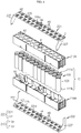
- FIG. 1 is a perspective view schematically showing a battery pack according to an embodiment of the present disclosure.
- FIG. 2 is a perspective front view schematically showing a battery module, employed at the battery pack according to an embodiment of the present disclosure.
- FIG. 3 is a perspective rear view schematically showing the battery module, employed at the battery pack according to an embodiment of the present disclosure.
- FIG. 4 is an exploded perspective view showing components of the battery module, employed at the battery pack according to an embodiment of the present disclosure.
- a battery pack 1000 includes a plurality of battery modules 200, 201, 202, 203, 204, 205, 206 arranged in the front and rear direction.
- the battery module 200 may include a plurality of cylindrical battery cells 100, a module housing 210, and a connection plate 220.
- the cylindrical battery cell 100 may include a cylindrical battery can 120 and an electrode assembly (not shown) accommodated in the battery can 120.
- the cylindrical battery cell 100 may be configured such that the battery can 120 stands up in the vertical direction.
- the battery can 120 may include a material with high electrical conductivity.
- the battery can 120 may include an aluminum or copper.
- electrode terminals 111a, 111b may be formed at an upper portion and a lower portion of the battery can 120, respectively.
- a first electrode terminal 111a may be formed at a flat circular upper surface of the upper end of the battery can 120
- a second electrode terminal 111b may be formed at a flat circular bottom of the lower end of the battery can 120.
- an electrical insulation member may be coated on a side portion of the battery can 120. That is, since the battery can 120 is electrically connected to the electrodes of the electrode assembly therein, for example, an insulating film (not shown) may be coated to surround the side portion of the battery can 120 in order to prevent an unintended conductive object from contacting the battery can 120 and causing electricity leakage.
- the electrode assembly (not shown) may be wound in a jelly-roll form in a state where a separator is interposed between a positive electrode and a negative electrode.
- a positive electrode tab may be attached to the positive electrode (not shown) and connected to the first electrode terminal 111a at the upper end of the battery can 120.
- a negative electrode tab may be attached to the negative electrode (not shown) and connected to the second electrode terminal 111b at the lower end of the battery can 120.
- the plurality of cylindrical battery cells 100 may be arranged in the horizontal direction to stand up in the vertical direction inside the module housing 210.
- one battery module 200 includes 23 cylindrical battery cells 100.
- the 23 cylindrical battery cells 100 may be arranged to be adjacent to each other in the horizontal direction in a state of standing up in the vertical direction. Further, the positive electrode of the cylindrical battery cell 100 may be formed at the upper end thereof, and the negative electrode may be formed at the lower end thereof.
- the terms indicating directions such as front, rear, left, right, upper and lower, used in this specification, may vary depending on the position of an observer or the shape of an object.
- the front, rear, left, right, upper and lower directions are distinguished based on the case where viewed in the F direction.
- the module housing 210 may be formed to have an inner space in which the plurality of cylindrical battery cells 100 are inserted and accommodated. Specifically, the module housing 210 may have a plurality of hollows H1 formed to surround the outer surface of the cylindrical battery cell 100. Further, the module housing 210 may include left and right outer walls 210c, 210d and front and rear outer walls 210a, 210b.
- the module housing 210 may include an upper case 210A and a lower case 210B.
- the upper case 210A may have a hollow H1 formed to surround the outer surface of the upper portion of the cylindrical battery cell 100.
- the lower case 210B may be fastened to the lower portion of the upper case 210A and have a hollow H1 formed to surround the outer surface of the lower portion of the cylindrical battery cell 100.
- a coupling protrusion 213 may be formed on the front outer wall 210a of the module housing 210 to protrusively extend from the outer surface of the outer wall 210a.
- a guide groove 215 dented inward from the outer surface of the outer wall 210b may be formed at the rear outer wall 210b of the module housing 210 so that the coupling protrusion 213 is inserted therein.
- two coupling protrusions 213 may be formed on the front outer wall 210a of the module housing 210.
- two guide grooves 215 may be formed at the rear outer wall 210b of the module housing 210.
- the coupling protrusion 213 of the module housing 210 of the present disclosure may be inserted into the guide groove 215 of another battery module 200 to guide the arrangement of the plurality of battery modules 200, the battery modules 200 may not only be arranged easily and but also be fixed to each other without being easily separated.
- connection plate 220 may include a body portion 225 and a connection portion 227.
- the body portion 225 may be located at an upper portion or a lower portion of the plurality of cylindrical battery cells 100. That is, the body portion 225 may be mounted to the upper portion or the lower portion of the module housing 210.
- a guide protrusion P1 protruding upward or downward may be formed at the upper portion or the lower portion of the module housing 210 to guide a location at which the body portion 225 of the connection plate 220 is mounted.
- the connection plate 220 may have a guide hole H4 perforated such that the guide protrusion P1 is inserted therein.
- connection plate 220 may include an electrically conductive material.
- the electrically conductive material may be a metal alloy mainly including copper, nickel, aluminum, gold, silver, or the like.
- the battery module 200 may have two connection plates 221, 222 respectively located at the upper portion and the lower portion of the plurality of cylindrical battery cells 100.
- three guide holes H4 may be formed in the connection plate 221 mounted to the upper portion of the module housing 210, and three guide protrusions P1 may be formed on the upper portion of the module housing 210.
- three guide holes H4 may be formed in the connection plate 222 mounted to the lower portion of the module housing 210, and three guide protrusions P1 (not shown) may be formed on the lower portion of the module housing 210.
- the body portion 225 may include a plurality of connection terminals 225c provided in a partial region thereof to be in electrical contact and connection with the electrode terminals 111 of the plurality of cylindrical battery cells 100.
- connection opening H3 perforated in a vertical direction may be formed in the body portion 225.
- connection terminal 225c of the connection plate 220 may be formed to protrusively extend in a horizontal direction from an inner side of the edge of the connection opening H3 to be in electrical contact and connection with the electrode terminals 111 formed at the plurality of cylindrical battery cells 100.
- the protrusively extending end of the connection terminal 225c may have a branched structure that is split into two sides with respect to the protrusively extending direction.
- connection openings H3 may be formed in each of the two connection plates 221, 222.
- 23 connection terminals 225c may be respectively formed at the 23 connection openings H3 to protrusively extend horizontally from the inner side of the edge thereof.
- the connection terminal 225c may have a branched structure that is split into two sides with respect to the protrusively extending direction.
- connection portion 227 may be formed to protrusively extend in a left direction or a right direction from the body portion 225. Also, the protrusively extending portion of the connection portion 227 may be bent upward or downward from the body portion 225. In addition, the bent end of the connection portion 227 may be in contact and connection with a portion of the other connection plate 220.
- connection portions 227 bent and extending downward from left and right ends of the body portion 225 may be formed at the connection plate 221 mounted to the upper portion of the module housing 210 of one battery module 200.
- the bent end of the connection portion 227 may be in contact and connection with a portion of the connection plate 222 of another battery module 206.
- two connection portions 227 bent and extending upward from the left and right ends of the body portion 225 may be formed at the connection plate 222 mounted to the lower portion of the module housing 210.
- the bent end of the connection portion 227 may be in contact and connection with a portion of the other connection plate 220.
- connection plate 220 having the body portion 225 mounted to the upper portion or the lower portion of the module housing 210 and the connection portion 227 extending in the left and right direction of the body portion 225 and bent upward or downward, unlike from the conventional battery pack 1000, the connection plates 220 may be in contact and connection with each other in the left and right direction of the module housing 210. Accordingly, unlike the conventional art, it is not necessary to secure a space in the front and rear direction for allowing the connection plates 221, 222 to contact and connect each other inside the module housing, thereby implementing the battery module 200 with a slimmer design in the front and rear direction. Ultimately, the energy density of the battery pack 1000 may be maximized.
- connection plate 220 may include a first connection plate 221 and a second connection plate 222.
- the body portion 225 may be located at the upper portion of the plurality of cylindrical battery cells 100.
- the connection portion 227 protrusively extending from the body portion 225 may be bent downward.
- the first connection plate 221 may be electrically connected (bonded) with the electrode terminals 111a located at the upper portion of the plurality of cylindrical battery cells 100.
- the connection portion 227 of the first connection plate 221 may be in electrical contact (bond) with the connection portion 227 of the second connection plate 222 provided to another battery module 200.
- the connection terminal 225c of the first connection plate 221 may be bonded to the first electrode terminal 111a of the plurality of cylindrical battery cells 100 by means of resistance welding.
- the body portion 225 may be located at the lower portion of the plurality of cylindrical battery cells 100, and the connection portion 227 protrusively extending from the body portion 225 may be bent upward.
- the second connection plate 222 may be in electric connection (contact) with the electrode terminal 111b located at the lower portion of the plurality of cylindrical battery cells 100.
- the connection portion 227 of the second connection plate 222 may be in electrical contact with the connection portion 227 of the first connection plate 221 provided to another battery module 200.
- the connection terminal 225c of the second connection plate 222 may be bonded to the second electrode terminal 111b of the plurality of cylindrical battery cells 100 by means of resistance welding.
- connection portion 227 of at least one of the first connection plate 221 and the second connection plate 222 may have an expanded structure 221b protrusively extending forward further to a foremost terminal of the module housing 210.
- connection portion 227 of at least one of the first connection plate 221 and the second connection plate 222 may have an expanded structure 221b protrusively extending rearward further to a rearmost terminal of the module housing 210.
- connection portion 227 of the first connection plate 221 may have an expanded structure 221b protrusively extending forward further to the foremost terminal of the module housing 210.
- connection portion 227 of the second connection plate 222 may have an expanded structure (not shown) protrusively extending rearward further to the rearmost terminal of the module housing 210.
- the battery pack 1000 may include seven battery modules 200.
- the battery pack 1000 may include 14 connection plates 220.
- the connection portions of six first connection plate 221 provided to each of the seven battery modules 200 may be formed to protrusively extend forward further to the foremost terminal of the module housing 210 so as to be in contact with the connection portions 227 of the six second connection plates 222.
- connection portion 227 of at least one of the first connection plate 221 and the second connection plate 222 has the expanded structure 221b protrusively extending forward further to the foremost terminal of the module housing 210 or protrusively extending rearward further to the rearmost terminal of the module housing 210, one connection plate 221 may be in contact with the other connection plate 222 without a separate connection member. Accordingly, the manufacturing cost of the battery pack 1000 may be reduced and the manufacturing process may be simplified.
- any one battery module 206 may include an external input/output bus bar 290.
- the external input/output bus bar 290 may be provided to the battery module 206 located at an outermost front side. Further, the external input/output bus bar 290 may be electrically connected to the first connection plate 221 of the battery module 206. In addition, the external input/output bus bar 290 may be bent forward, and then its bent end may be bent again upward.
- FIG. 5 is a side view schematically showing the battery pack according to an embodiment of the present disclosure.
- a rib R1 may be formed at the outer wall 210d of the module housing 210 to protrusively extend in the horizontal direction from an outer surface thereof.
- the rib R1 may be formed at the left and right outer wall 210d of the module housing 210.
- the rib R1 may have a protruding wall having a structure extending in the vertical direction and a structure extending in the front and rear direction.
- the protruding wall may have a shape protrusively extending outward from an outer wall of the hollow H1 or an outer wall of the fixing tube 212 located outside the module housing 210.
- the rib R1 may be formed to support the connection portions 227 of the first connection plate 221 and the second connection plate 222 in an outer direction (the horizontal direction).
- the protruding wall of the rib R1 of the module housing 210 of the battery module 206 is formed at a location facing a region S' where the connection portion 227 of the first connection plate 221 and the connection portion 227 of the second connection plate 222 overlap each other to support the connection portions 227 outward.
- the outer wall 210d of the module housing 210 has the rib R1 protrusively extending in the horizontal direction from the outer surface thereof, it is possible to secure a predetermined mechanical rigidity of the outer wall 210d of the module housing 210 and form an empty space in the outer wall 210d of the module housing 210, thereby reducing the weight of the module housing 210. Also, since the rib R1 has the protruding wall protrusively extending outward to support the connection portions 227 of the first connection plate 221 and the second connection plate 222, the welding process may be easily performed between the connection plates 220.
- the rib R1 may form an empty space between the outer wall 210d of the module housing 210 and the connection portions 227 of the first connection plate 221 and the second connection plate 222, it is possible to minimize the damage to the module housing 210 caused by the heat of welding.
- the module housing 210 may include a fixing tube 212 having a hollow structure H5 penetrated in the vertical direction.
- the fixing tube 212 may be located at left and right outer sides, respectively.
- the fixing tube 212 may be located at a left rear end of the module housing 210.
- another fixing tube 212 may be located at a right rear end of the module housing 210.
- the fixing tube 212 may be used to insert a fixing bolt (not shown) for fixing the battery module 200 to a floor or a ceiling at a specific installation location.
- the fixing tube 212 having the hollow structure H5 is provided to the module housing 210, a fixing bolt may be easily inserted and fixed such that the battery pack 1000 including the plurality of battery modules 200 may be stably fixed to an installation site.
- the fixing tube 212 may have a vertical terminal protrusively extending in a vertical direction to the upper surface or the lower surface of the module housing 210, respectively.
- a guide holes H2 perforated in a vertical direction may be formed in the body portion 225 so that the terminal of the fixing tube 212 protruding in a vertical direction is inserted therein.
- the terminal of the fixing tube 212 protruding upward may have a structure protruding upward further to the upper surface of the module housing 210.
- the terminal of the fixing tube 212 protruding downward may have a structure protruding downward further to the lower surface of the module housing 210.
- two guide holes H2 may be formed in the body portion 225 of the first connection plate 221.
- the terminal of the fixing tube 212 protruding upward may be inserted into each of the two guide holes H2.
- two guide holes H2 may be formed in the body portion 225 of the second connection plate 222.
- the terminal of the fixing tube 212 protruding downward may be inserted into each of the two guide holes H2.
- the first connection plate 221 and the second connection plate 222 may be guided to be mounted in place at the upper portion or the lower portion of the module housing 210. Accordingly, the connection terminals 225c of the first connection plate 221 and the second connection plate 222 may be disposed at locations corresponding to the electrode terminals 111 of the plurality of cylindrical battery cells 100, thereby increasing the manufacturing efficiency and the product completion more effectively.
- connection portion 227 may be located to face the left and right outer sides of the fixing tube 212 located at the outer wall 210d.
- the fixing tube 212 provided to the module housing 210 has a hollow structure H5 with an empty inside.
- the fixing tube 212 may be formed adjacent to the left and right outer walls 210d of the module housing 210 to give a predetermined distance between the connection portions 227 and the plurality of cylindrical battery cells 100 welded to each other for electrical connection between the first connection plate 221 and the second connection plate 222.
- the overlapped region S' of the connection portions 227 of the first connection plate 221 and the second connection plate 222 is located to face the left outer side or the right outer side of the fixing tube 212, the amount of heat generated during the welding process of the connection portion 227 and transferred to the cylindrical battery cells 100 of the battery module 200 may be minimized. Accordingly, it is possible to prevent that the performance of the cylindrical battery cell 100 deteriorates or a fire occurs due to overheating that may occur in the welding process, thereby effectively reducing the defective rate.
- FIG. 6 is a side view schematically showing a battery module, employed at the battery pack according to another embodiment of the present disclosure.
- a protection plate 214 having a plate shape with a predetermined thickness may be formed at left and right outer walls of the module housing 210. Specifically, the protection plate 214 may be ridged outward from the left and right outer walls 210d of the module housing 210.
- the protection plate 214 may have a size corresponding to the size of the portion S' ( FIG. 5 ) where the connection portions 227 of the first connection plate 221 and the second connection plate 222 overlap each other.
- the protection plate 214 may be formed at a location corresponding to the location of the overlapped region of the connection portions 227 of the first connection plate 221 and the second connection plate 222.
- the protection plate 214 having a plate shape with a predetermined thickness may be formed at the right outer wall 210d of the module housing 210.
- the protection plate 214 may be located at a portion where the connection portions 227 of the first connection plate 221 and the second connection plate 222 overlap each other.
- the module housing 210 since the module housing 210 includes the protection plate 214 having a plate shape with a predetermined thickness and formed at the left and right outer walls thereof, when the connection portions 227 of the first connection plate 221 and the second connection plate 222 are welded to each other, the welding heat may be prevented from being conducted into the inside of the module housing 210. As a result, it is possible to minimize damage to the battery module 200 caused by welding between the connection plates 220.
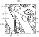
- FIG. 7 is a perspective view schematically showing a battery pack according to another embodiment of the present disclosure. Also, FIG. 8 is an enlarged view schematically showing a region A' of the battery pack of FIG. 7 .
- the battery module 200B, 201B, 202B, 203B of the battery pack 1000B may further include a protection member 230 having a plate shape with a predetermined thickness. Specifically, at least a portion of the protection member 230 may be inserted and fixed at a location (portion) of the outer wall 210d of the module housing 210 facing the connection portion 227.
- the protection member 230 may include a material with a large specific heat or a material with low thermal conductivity.
- the protection member 230 may include a metal or plastic with low thermal conductivity and excellent heat resistance. More specifically, the protection member 230 may be a plastic material with excellent heat resistance such as aromatic polyamide, polyimide, polysulfone, polyimidazole pyrrolone, polybenzoimidazole, polyphenylene oxide and the like.
- the protection member 230 having a plate shape with a predetermined thickness may be inserted into the right outer wall 210d of the module housing 210.
- the protection member 230 may be located to correspond to a portion where the connection portions 227 of the first connection plate 221 and the second connection plate 222 overlap each other.
- the protection member 230 is inserted and fixed at a location (portion) of the outer wall 210d of the module housing 210 facing the connection portion 227, when the connection portions 227 of the first connection plate 221 and the second connection plate 222 are welded to each other, it is possible to reduce the amount of welding heat conducted into the inside of the module housing 210 or to prevent the module housing 210 from being melted and damaged. As a result, damage to the battery module 200 caused by welding between the connection plates 221, 222 may be minimized.
- connection portion 227 may have a bent structure B1 at which an end thereof is bent upward or downward.
- connection portion 227 of any one of the first connection plate 221 and the second connection plate 222 may have the bent structure B1 at an upper end or a lower end.
- an end area of the bent structure may be equal to or smaller than the overlapped size of the connection portions 227 of the first connection plate 221 and the second connection plate 222.
- the bent structure B1 may be formed at a region where the connection portions 227 of the first connection plate 221 and the second connection plate 222 are welded to each other.
- a gap of a predetermined distance may be formed between the end of the connection portion 227 and the bent structure B1. This gap may effectively reduce the amount of welding heat generated during the welding process of the connection portions 227 and conducted to the inside of the module housing 210.
- a bent structure B1 may be further formed at an upper end of the connection portion 227 of the second connection plate 222.
- the portion where the bent structure B1 of the connection portion 227 of the second connection plate 222 is formed may overlap the connection portion 227 of the first connection plate 221.
- the end of the connection portion 227 of the second connection plate 222 and the bent structure B1 may be welded to the end of the connection portion 227 of the first connection plate 221.
- connection portion 227 of the first connection plate 221 and the second connection plate 222 are welded to each other, it is possible to effectively reduce the amount of generated welding heat conducted to the inside of the module housing 210, without any separate member. Accordingly, damage to the battery module 200 caused by welding between the connection plates 220 may be minimized.
- a fixing hole H6 may be formed in the connection portions 227 of each of the first connection plate 221 and the second connection plate 222.
- a fixing protrusion P2 may be formed on the outer wall 210d of the module housing 210.
- the fixing hole H6 may have a shape perforated in the left and right direction so that a protruding portion of the fixing protrusion P2 may be inserted therein.
- the fixing protrusion P2 may protrude from the outer wall 210d of the module housing 210 in the left or right direction.
- connection portion 227 of each of the first connection plate 221 and the second connection plate 222 may be guided to be placed at a suitable location on left and right outer walls of the module housing 210. Accordingly, the assembling process may be easily performed, thereby shortening the manufacturing time.
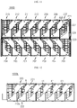
- FIG. 9 is a perspective view schematically showing a battery pack according to an embodiment of the present disclosure.
- the battery pack 1000C of the present disclosure may further include a plurality of other battery modules 207, 208, 209, 210, 211, 212, 213 located above the plurality of battery modules 200, 201, 202, 203, 204, 205, 206.
- the plurality of other battery modules located on top of the plurality of battery modules 200, 201, 202, 203, 204, 205, 206 and the plurality of other battery modules 207, 208, 209, 210, 211, 212, 213 located above the plurality of battery modules 200, 201, 202, 203, 204, 205, 206 may be mounted to a mounting structure 280.
- the mounting structure 280 may include pillar portions 281 respectively located at front and rear sides thereof and having a vertically standing plate shape, and a mounting portion 283 connected to the front and rear pillar portions 281 so that the plurality of battery modules 200 are located therebelow and mounted thereon, the mounting portion 283 having a plate shape lying down in the horizontal direction. That is, the mounting structure 280 may have an 'H' shape as a whole.
- the mounting structure 280 may include a material such as steel, stainless steel, or the like plated with a non-conductive material through which electricity does not pass.
- the pillar portion 281 may have a beading structure 285 formed therein and ridged inward or outward.
- the beading structure 285 may increase the mechanical rigidity of the pillar portion 281.
- the mounting structure 280 may be made of steel or stainless steel.
- connection bus bar 240 may be provided to electrically connect at least two first connection plates 221, or at least two second connection plates 222, or the first connection plate 221 and the second connection plate 222, respectively provided at the plurality of battery modules 200, 201, 202, 203, 204, 205, 206 and the plurality of other battery modules 207, 208, 209, 210, 211, 212, 213 located above the plurality of battery modules 200, 201, 202, 203, 204, 205, 206.
- the connection bus bar 240 may include an electrically conductive material.
- the electrically conductive material may be a metal alloy mainly containing copper, nickel, aluminum, gold, silver, and the like.
- connection bus bar 240 may include a first contact portion 242, a second contact portion 244, and a detouring portion 246.
- first contact portion 242 may have a plate elongated downward to be in contact with any one of the first connection plate 221 and the second connection plate 222.
- second contact portion 244 may have a plate elongated upward to be in contact with the other of the first connection plate 221 and the second connection plate 222.
- both ends of the detouring portion 246 may be connected with the first contact portion 242 and the second contact portion 244, respectively.
- the detouring portion 246 may have a plate stepped outward from the first contact portion 242 and the second contact portion 244.
- one connection bus bar 240 may be provided to electrically connect two second connection plates 222 provided at the battery modules 200, 201, 202, 203, 204, 205, 206 located in a first layer (a lower side) of the battery pack 1000C and the battery modules 207, 208, 209, 210, 211, 212, 213 located in a second layer (an upper side) of the battery pack 1000C.
- connection bus bar 240 may include a first contact portion 242 in contact with the second connection plate 222 provided to the battery module 205 of the first layer and a second contact portion 244 in contact with the second connection plate 222 of the battery module 207 of the second layer.
- a detouring portion 246 configured to connect the first contact portion 242 and the second contact portion 244 to each other and stepped outward from the first contact portion 242 and the second contact portion 244 may be provided.
- the battery pack 1000C includes the connection bus bar 240 having the first contact portion 242, the second contact portion 244 and the detouring portion 246, the plurality of battery modules 200 and the plurality of other battery modules 200 located thereabove may electrically connected in an easy way without causing shorting between the plurality of battery modules 200, 201, 202, 203, 204, 205, 206 and the plurality of other battery modules 207, 208, 209, 210, 211, 212, 213, thereby increasing the manufacturing efficiency and safety.
- FIG. 10 is a perspective view schematically showing a third connection plate of a battery module according to still another embodiment of the present disclosure.
- FIG. 11 is a side view schematically showing a battery pack according to still another embodiment of the present disclosure.
- a battery pack 1000D may include a plurality of battery modules 200, 201, 202, 203, 204, 205, 206, a plurality of other battery modules 207, 208, 209, 210, 211, 212, 213 located above or below the plurality of battery modules 200, 201, 202, 203, 204, 205, 206, and a third connection plate 223 configured to electrically connect the plurality of battery modules 200, 201, 202, 203, 204, 205, 206 and the plurality of other battery modules 207, 208, 209, 210, 211, 212, 213 located thereabove or therebelow.
- the battery pack 1000D may further include a plurality of other battery modules 207, 208, 209, 210, 211, 212, 213 located in a second layer provided above the plurality of battery modules 200, 201, 202, 203, 204, 205, 206 located in a first layer (a lower side).
- the plurality of other battery modules 207, 208, 209, 210, 211, 212, 213 of the second layer located at the upper side of the battery pack 1000D may be arranged in a direction opposite to the arrangement direction of the plurality of battery modules 200, 201, 202, 203, 204, 205, 206 of the first layer located at the lower side of the battery pack 1000D.
- the plurality of battery modules 200, 201, 202, 203, 204, 205, 206 of the first layer located at the lower side of the battery pack 1000D may be arranged from front to rear.
- the plurality of other battery modules 207, 208, 209, 210, 211, 212, 213 of the second layer located at the upper side of the battery pack 1000D may be arranged from rear to front.
- the battery pack 1000D may include a first connection plate 221 and a second connection plate 222 provided to any one battery module 205 among the plurality of battery modules 200, 201, 202, 203, 204, 205, 206 located in the first layer, and additionally include a third connection plate 223 electrically connected to the plurality of other battery modules 207, 208, 209, 210, 211, 212, 213.
- the third connection plate 223 include a body portion 225 having a plurality of connection terminals 225c located at the upper portion or the lower portion of the plurality of cylindrical battery cells 100 and in electrical contact and connection with the electrode terminal 111 formed at one of the plurality of cylindrical battery cells 100.
- the third connection plate 223 may include a second connection portion 229 configured to be in contact and connection with a portion of the connection plate 220 of the plurality of other battery modules 207, 208, 209, 210, 211, 212, 213 mounted to the upper side.
- the second connection portion 229 may be bent and extending upward or downward from the left or right end of the body portion 225.
- the third connection plate 223 may include a body portion 225 having a plurality of connection terminals 225c formed to be in electrical contact and connection with the electrode terminal 111 formed at one of the plurality of cylindrical battery cells 100. Further, the third connection plate 223 may include two second connection portions 229 formed at both left and right ends of the body portion 225 to be in contact and connection with a portion of the connection plate 220 of another battery module 207 mounted to the upper side. In addition, the two second connection portions 229 may be bent and extending upward.
- the plurality of battery modules 200, 201, 202, 203, 204, 205, 206 located in the lower side (the first layer) and the plurality of other battery modules 207, 208, 209, 210, 211, 212, 213 located in the upper side (the second layer) may be electrically connected to each other by means of the third connection plate 223.
- the plurality of cylindrical battery cells 100 of one battery module 205 may be electrically connected and simultaneously may be electrically connected to the connection plate 220 of another battery module 207 located at the upper side or the lower side. Accordingly, it is possible to shorten the manufacturing time of the battery pack and reduce the manufacturing cost.
- FIG. 12 is a side view schematically showing a battery module, employed at the battery pack according to another embodiment of the present disclosure. Also, FIG. 13 is an enlarged view schematically showing a region B' of the battery pack of FIG. 12 .
- the battery pack 1000E may include a plurality of battery modules 200.
- a hook structure K1 may be formed at the outer wall 210d of the module housing 210 provided to the battery module 200 such that the connection portion 227 of each of the connection plates 221, 222 is closely fixed to the outer wall 210d of the module housing 210.
- the hook structure K1 may protrusively extend from the outer wall 210d of the module housing 210 in the outer direction (the left and right direction).
- the battery pack 1000E may include seven battery modules 200.
- seven hook structures K1 may be formed at the left and right outer walls 210d of the module housings 210 respectively provided to the seven battery modules 200 such that the connection portions 227 of each of the connection plates 221, 222 is closely fixed to the outer wall of the module housing 210.
- connection portion 227 of the connection plate 220 may be fixed by the hook structure K1 protrusively extending outward. Accordingly, when the connection portions 227 of the two connection plates 220 are welded, the connection portions 227 may be stably fixed, thereby greatly increasing the welding efficiency. In addition, when an external shock is applied to the battery pack 1000, it is possible to prevent the connection portions 227 of the bonded connection plates 220 from being separated.
- the battery pack 1000 may include several electrical components (not shown) along with the plurality of battery modules 200, 201, 202, 203, 204, 205, 206.
- the electrical components are also referred to as electrical equipment.
- Representative examples of the electrical equipment included in the battery pack 1000 include a relay, a current sensor, a fuse, a battery management system (BMS), and the like.
- the electrical equipment is a component for managing charge and discharge of the cylindrical battery cells 100 included in the battery pack and ensuring safety, and may be regarded as an essential component of most battery packs.
- the present disclosure may provide an electronic device including the battery pack.
- the electronic device may be a large-capacity energy storage device including at least one battery pack.
- the electronic device may have an electronic system for checking or controlling the state of the battery pack.
- the present disclosure may provide a vehicle including the battery pack.
- the vehicle may be an electric vehicle including at least one battery pack.
- the vehicle may have an electronic system for checking or controlling the state of the battery pack.
- Reference Signs 1000 battery pack 100: cylindrical battery cells 200, 201, 202, 203, 204, 205, 206, 207, 208, 209, 210, 211, 212, 213: battery module 111, 111a, 111b: electrode terminal, first electrode terminal, second electrode terminal 220, 221, 222: connection plate, first connection plate, second connection plate 225: body portion 227: connection portion 210: module housing 210a, 210b, 210c, 210d: outer wall 221b: expanded structure
- H1 hollow H2: guide hole 214: protection member 230: protection member B1: bent structure
- 240 connection bus bar 242, 244, 246: first contact portion, second contact portion, detouring portion 223: third connection plate 229: second connection portion K1: hook structure
- H3 connection opening 225c: connection terminal 213, 215: coupling protrusion, guide groove
- the present disclosure relates to a battery pack including a connection plate.
- the present disclosure is available for industries associated with electronic devices or vehicles including the battery pack.
Abstract
Description
- The present disclosure relates to a battery pack including a connection plate, and more particularly, to a battery pack including a plurality of battery modules in a slimmer design and having an improved energy density.
- The present application claims priority to Korean Patent Application No.
10-2018-0118477 filed on October 4, 2018 - Secondary batteries are highly applicable to various products and has electrical characteristics with high energy density. The secondary battery is applied not only to portable electronic devices but also to electric vehicles, hybrid electric vehicles, power storage devices, and the like, driven by an electric driving source.
- The secondary battery is attracting attention as a new energy source for improving eco-friendliness and energy efficiency since the use of fossil fuels is significantly reduced and no by-product is generated during the use of energy.
- A battery pack applied to an electric vehicle has a structure in which a plurality of battery modules, each having a plurality of battery cells, are connected to obtain a high output. In addition, each battery cell is an electrode assembly including positive and negative electrode current collectors, a separator, an active material, an electrolyte, and the like to be repeatedly charged and discharged by an electrochemical reaction between the components.
- Recently, as the necessity for a large capacity structure increases along with application as an energy storage source, there is an increasing demand for a battery pack having a multi-module structure, in which a plurality of battery modules, each having a plurality of secondary batteries in series and/or in parallel, are aggregated. In this case, a plurality of battery modules are arranged in close contact in a front and rear direction so that a large number of battery modules are accommodated in a limited space inside the battery pack.
- In addition, the conventional battery pack has a metal plate configured to electrically connect a plurality of battery modules to each other and to electrically connect a plurality of cylindrical battery cells provided in each battery module.
- However, if a plurality of battery modules are closely arranged in the front and rear direction, a separate space for welding metal plates should be separately provided in a module housing of the battery module in order to connect a metal plate mounted to one battery module with a metal plate of another battery module.
- For this reason, the conventional battery module has a dead space formed in the module housing and thus has a limitation in including a larger number of cylindrical battery cells, and thus, the energy density of the battery pack greatly deteriorates.
- The present disclosure is designed to solve the problems of the related art, and therefore the present disclosure is directed to providing a battery pack, which may include a plurality of battery modules in a slimmer design and have an improved energy density.
- These and other objects and advantages of the present disclosure may be understood from the following detailed description and will become more fully apparent from the exemplary embodiments of the present disclosure. Also, it will be easily understood that the objects and advantages of the present disclosure may be realized by the means shown in the appended claims and combinations thereof.
- In one aspect of the present disclosure, there is provided a battery pack, comprising:
- a plurality of battery modules arranged in a front and rear direction,
- wherein each of the plurality of battery modules includes:
- a plurality of cylindrical battery cells arranged in a horizontal direction and having electrode terminals formed at an upper portion and a lower portion thereof, respectively;
- a module housing having a plurality of hollows in which the plurality of cylindrical battery cells are inserted and accommodated; and
- a connection plate having a body portion located at the upper portion or the lower portion of the plurality of cylindrical battery cells and provided with a plurality of connection terminals respectively in electrical contact and connection with the electrode terminal formed at one of the plurality of cylindrical battery cells, and a connection portion configured to protrusively extend in a left direction or a right direction from the body portion so that a protrusively extending portion of the connection portion is bent upward or downward from the body portion and a bent end of the connection portion is in contact and connection with a portion of another connection plate.
- Also, the connection plate may include a first connection plate having the body portion located at the upper portion of the plurality of cylindrical battery cells and having the connection portion protrusively extending from the body portion and bent downward; and a second connection plate having the body portion located at the lower portion of the plurality of cylindrical battery cells and having the connection portion protrusively extending from the body portion and bent upward.
- Moreover, the connection portion of the first connection plate may be in contact and connection with the connection portion of the second connection plate provided at another battery module.
- In addition, the connection portion of at least one of the first connection plate and the second connection plate may have an expanded structure protrusively extending forward further to a foremost terminal of the module housing or protrusively extending rearward further to a rearmost terminal of the module housing.
- Further, a rib may be formed at an outer wall of the module housing to protrusively extend in a horizontal direction from an outer surface thereof.
- Also, the module housing may include fixing tubes located at left and right outer sides thereof and having a hollow structure perforated in a vertical direction.
- Further, the fixing tube may have a vertical terminal protrusively extending in a vertical direction further to an upper surface or a lower surface of the module housing, and the body portion may have a guide hole perforated in a vertical direction so that the terminal of the fixing tube protruding in a vertical direction is inserted therein.
- Also, the connection portion may be located to face left and right outer sides of the fixing tube.
- Moreover, the module housing may include a protection plate ridged outward from the left and right outer walls thereof and having a plate shape with a predetermined thickness.
- In addition, the battery module may further include a protection member at least partially inserted and fixed in an outer wall of the module housing at a location facing the connection portion and having a plate shape with a predetermined thickness.
- Further, the connection portion may have a bent structure at which an end thereof is bent upward or downward.
- Also, the battery pack may further comprise a plurality of other battery modules located above the plurality of battery modules.
- Moreover, the battery pack may further comprise a plurality of other battery modules located above the plurality of battery modules, and a connection bus bar having an electrically conductive material is provided to electrically connect at least two of the first connection plates, or at least two of the second connection plates, or a first connection plate and a second connection plate, respectively included in the plurality of battery modules and the plurality of other battery modules located above the plurality of battery modules.
- In addition, the connection bus bar may include a first contact portion provided in contact with any one of the first connection plate and the second connection plate; a second contact portion provided in contact with the other of the first connection plate and the second connection plate; and a detouring portion having both ends respectively connected to the first contact portion and the second contact portion, the detouring portion being stepped outward from the first contact portion and the second contact portion.
- Further, the battery pack may further comprise a plurality of battery modules; a plurality of other battery modules located above or below the plurality of battery modules; and a third connection plate configured to electrically connect the plurality of battery modules and the plurality of other battery modules located above or below the plurality of battery modules.
- Also, the third connection plate may include a body portion located at the upper portion or the lower portion of the plurality of cylindrical battery cells and having a plurality of connection terminals respectively in electrical contact and connection with the electrode terminal formed at one of the plurality of cylindrical battery cells; and a second connection portion configured to be bent and extending upward or downward from a left or right end of the body portion to be in contact and connection with a portion of a connection plate of another battery module mounted to an upper side.
- Moreover, a hook structure may be formed at left and right outer walls of the module housing to protrusively extend outward from the outer walls of the module housing so that the connection portion of the connection plate is closely fixed to the outer wall of the module housing.
- In addition, in another aspect of the present disclosure, there is also provided an electronic device comprising the battery pack according to the present disclosure.
- Further, in another aspect of the present disclosure, there is also provided a vehicle comprising the battery pack according to the present disclosure.
- According to an embodiment of the present disclosure, since the battery pack of the present disclosure includes a connection plate having a body portion mounted to the upper portion or the lower portion of the module housing and a connection portion extending in the left and right direction of the body portion and bent upward or downward, unlike the conventional battery pack, the connection plates may be in contact and connection with each other at the left and right outer sides of the module housing. Accordingly, unlike the conventional art, it is not necessary to secure a space for contact and connection between the connection plates in the module housing, thereby enabling a slimmer battery module. Ultimately, the slim battery pack may have a maximized energy density.
- Also, according to this embodiment of the present disclosure, since the connection portion of at least one of the first connection plate and the second connection plate has the expanded structure protrusively extending forward further to the foremost terminal of the module housing or protrusively extending rearward further to the rearmost terminal of the module housing, one connection plate may be in contact with the other connection plate without a separate connection member. Accordingly, the manufacturing cost of the battery pack may be reduced and the manufacturing process may be simplified.
- Moreover, according to an embodiment of the present disclosure, since the outer wall of the module housing has the rib protrusively extending in the horizontal direction from the outer surface thereof, it is possible to secure a predetermined mechanical rigidity of the outer wall of the module housing and form an empty space in the outer wall of the module housing, thereby reducing the weight of the module housing.
- Also, since the rib of the present disclosure has the protruding wall protrusively extending outward to support the connection portions of the first connection plate and the second connection plate, the welding process may be easily performed between the connection plates. In addition, since the rib may form an empty space between the outer wall of the module housing and the connection portions of the first connection plate and the second connection plate, it is possible to minimize the damage to the module housing caused by the heat of welding.
- In addition, according to an embodiment of the present disclosure, since the overlapped region of the connection portions of the first connection plate and the second connection plate is located to face the left outer side or the right outer side of the fixing tube, namely since the connection portions are located as far from the cylindrical battery cells as possible, the amount of heat generated during the welding process of the connection portion and transferred to the cylindrical battery cells of the battery module may be minimized. Accordingly, it is possible to prevent that the performance of the cylindrical battery cell deteriorates or a fire occurs due to overheating that may occur in the welding process, thereby effectively reducing the defective rate.
- Further, according to an embodiment of the present disclosure, since the protection member is inserted and fixed at a location (portion) of the outer wall of the module housing facing the connection portion, when the connection portions of the first connection plate and the second connection plate are welded to each other, it is possible to reduce the amount of welding heat conducted into the inside of the module housing or to prevent the module housing from being melted and damaged. As a result, damage to the battery module caused by welding between the connection plates may be minimized.
- Also, according to an embodiment of the present disclosure, since the bent structure is formed at the end of the connection portion bent upward or downward, when the connection portions of the first connection plate and the second connection plate are welded to each other, it is possible to effectively reduce the amount of generated welding heat conducted to the inside of the module housing, without any separate member. Accordingly, damage to the battery module caused by welding between the connection plates may be minimized.
- The accompanying drawings illustrate a preferred embodiment of the present disclosure and together with the foregoing disclosure, serve to provide further understanding of the technical features of the present disclosure, and thus, the present disclosure is not construed as being limited to the drawing.
-
FIG. 1 is a perspective view schematically showing a battery pack according to an embodiment of the present disclosure. -
FIG. 2 is a perspective front view schematically showing a battery module, employed at the battery pack according to an embodiment of the present disclosure. -
FIG. 3 is a perspective rear view schematically showing the battery module, employed at the battery pack according to an embodiment of the present disclosure. -
FIG. 4 is an exploded perspective view showing components of the battery module, employed at the battery pack according to an embodiment of the present disclosure. -
FIG. 5 is a side view schematically showing the battery pack according to an embodiment of the present disclosure. -
FIG. 6 is a side view schematically showing a battery module, employed at the battery pack according to another embodiment of the present disclosure. -
FIG. 7 is a perspective view schematically showing a battery pack according to another embodiment of the present disclosure. -
FIG. 8 is an enlarged view schematically showing a region A' of the battery pack ofFIG. 7 . -
FIG. 9 is a perspective view schematically showing a battery pack according to an embodiment of the present disclosure. -
FIG. 10 is a perspective view schematically showing a third connection plate of a battery module according to still another embodiment of the present disclosure. -
FIG. 11 is a side view schematically showing a battery pack according to still another embodiment of the present disclosure. -
FIG. 12 is a side view schematically showing a battery module, employed at the battery pack according to another embodiment of the present disclosure. -
FIG. 13 is an enlarged view schematically showing a region B' of the battery pack ofFIG. 12 . - Hereinafter, preferred embodiments of the present disclosure will be described in detail with reference to the accompanying drawings. Prior to the description, it should be understood that the terms used in the specification and the appended claims should not be construed as limited to general and dictionary meanings, but interpreted based on the meanings and concepts corresponding to technical aspects of the present disclosure on the basis of the principle that the inventor is allowed to define terms appropriately for the best explanation.
- Therefore, the description proposed herein is just a preferable example for the purpose of illustrations only, not intended to limit the scope of the disclosure, so it should be understood that other equivalents and modifications could be made thereto without departing from the scope of the disclosure.
-
FIG. 1 is a perspective view schematically showing a battery pack according to an embodiment of the present disclosure.FIG. 2 is a perspective front view schematically showing a battery module, employed at the battery pack according to an embodiment of the present disclosure.FIG. 3 is a perspective rear view schematically showing the battery module, employed at the battery pack according to an embodiment of the present disclosure. Also,FIG. 4 is an exploded perspective view showing components of the battery module, employed at the battery pack according to an embodiment of the present disclosure. - Referring to
FIGS. 1 to 4 , abattery pack 1000 according to the present disclosure includes a plurality ofbattery modules - Specifically, the
battery module 200 may include a plurality ofcylindrical battery cells 100, amodule housing 210, and aconnection plate 220. - Here, the
cylindrical battery cell 100 may include a cylindrical battery can 120 and an electrode assembly (not shown) accommodated in the battery can 120. - Here, the
cylindrical battery cell 100 may be configured such that the battery can 120 stands up in the vertical direction. Also, the battery can 120 may include a material with high electrical conductivity. For example, the battery can 120 may include an aluminum or copper. - In addition,
electrode terminals first electrode terminal 111a may be formed at a flat circular upper surface of the upper end of the battery can 120, and asecond electrode terminal 111b may be formed at a flat circular bottom of the lower end of the battery can 120. - Also, an electrical insulation member may be coated on a side portion of the battery can 120. That is, since the battery can 120 is electrically connected to the electrodes of the electrode assembly therein, for example, an insulating film (not shown) may be coated to surround the side portion of the battery can 120 in order to prevent an unintended conductive object from contacting the battery can 120 and causing electricity leakage.
- In addition, the electrode assembly (not shown) may be wound in a jelly-roll form in a state where a separator is interposed between a positive electrode and a negative electrode. A positive electrode tab may be attached to the positive electrode (not shown) and connected to the
first electrode terminal 111a at the upper end of the battery can 120. A negative electrode tab may be attached to the negative electrode (not shown) and connected to thesecond electrode terminal 111b at the lower end of the battery can 120. - Further, when viewed in the F direction, the plurality of
cylindrical battery cells 100 may be arranged in the horizontal direction to stand up in the vertical direction inside themodule housing 210. - For example, as shown in
FIG. 4 , onebattery module 200 includes 23cylindrical battery cells 100. The 23cylindrical battery cells 100 may be arranged to be adjacent to each other in the horizontal direction in a state of standing up in the vertical direction. Further, the positive electrode of thecylindrical battery cell 100 may be formed at the upper end thereof, and the negative electrode may be formed at the lower end thereof. - Here, the terms indicating directions such as front, rear, left, right, upper and lower, used in this specification, may vary depending on the position of an observer or the shape of an object. However, in this specification, for convenience of description, the front, rear, left, right, upper and lower directions are distinguished based on the case where viewed in the F direction.
- Here, the
module housing 210 may be formed to have an inner space in which the plurality ofcylindrical battery cells 100 are inserted and accommodated. Specifically, themodule housing 210 may have a plurality of hollows H1 formed to surround the outer surface of thecylindrical battery cell 100. Further, themodule housing 210 may include left and rightouter walls outer walls - In addition, the
module housing 210 may include anupper case 210A and alower case 210B. - Here, in the
upper case 210A may have a hollow H1 formed to surround the outer surface of the upper portion of thecylindrical battery cell 100. Further, thelower case 210B may be fastened to the lower portion of theupper case 210A and have a hollow H1 formed to surround the outer surface of the lower portion of thecylindrical battery cell 100. - In addition, a
coupling protrusion 213 may be formed on the frontouter wall 210a of themodule housing 210 to protrusively extend from the outer surface of theouter wall 210a. Also, aguide groove 215 dented inward from the outer surface of theouter wall 210b may be formed at the rearouter wall 210b of themodule housing 210 so that thecoupling protrusion 213 is inserted therein. - For example, as shown in
FIG. 2 , twocoupling protrusions 213 may be formed on the frontouter wall 210a of themodule housing 210. In addition, as shown inFIG. 3 , twoguide grooves 215 may be formed at the rearouter wall 210b of themodule housing 210. - Thus, according to this configuration of the present disclosure, since the
coupling protrusion 213 of themodule housing 210 of the present disclosure may be inserted into theguide groove 215 of anotherbattery module 200 to guide the arrangement of the plurality ofbattery modules 200, thebattery modules 200 may not only be arranged easily and but also be fixed to each other without being easily separated. - In addition, the
connection plate 220 may include abody portion 225 and aconnection portion 227. Specifically, thebody portion 225 may be located at an upper portion or a lower portion of the plurality ofcylindrical battery cells 100. That is, thebody portion 225 may be mounted to the upper portion or the lower portion of themodule housing 210. In this case, a guide protrusion P1 protruding upward or downward may be formed at the upper portion or the lower portion of themodule housing 210 to guide a location at which thebody portion 225 of theconnection plate 220 is mounted. In addition, theconnection plate 220 may have a guide hole H4 perforated such that the guide protrusion P1 is inserted therein. - Further, the
connection plate 220 may include an electrically conductive material. For example, the electrically conductive material may be a metal alloy mainly including copper, nickel, aluminum, gold, silver, or the like. - For example, as shown in
FIG. 4 , thebattery module 200 may have twoconnection plates cylindrical battery cells 100. In addition, three guide holes H4 may be formed in theconnection plate 221 mounted to the upper portion of themodule housing 210, and three guide protrusions P1 may be formed on the upper portion of themodule housing 210. Further, three guide holes H4 may be formed in theconnection plate 222 mounted to the lower portion of themodule housing 210, and three guide protrusions P1 (not shown) may be formed on the lower portion of themodule housing 210. - Further, the
body portion 225 may include a plurality ofconnection terminals 225c provided in a partial region thereof to be in electrical contact and connection with the electrode terminals 111 of the plurality ofcylindrical battery cells 100. - Specifically, at least one connection opening H3 perforated in a vertical direction may be formed in the
body portion 225. Also, theconnection terminal 225c of theconnection plate 220 may be formed to protrusively extend in a horizontal direction from an inner side of the edge of the connection opening H3 to be in electrical contact and connection with the electrode terminals 111 formed at the plurality ofcylindrical battery cells 100. Moreover, the protrusively extending end of theconnection terminal 225c may have a branched structure that is split into two sides with respect to the protrusively extending direction. - For example, as shown in
FIG. 4 , 23 connection openings H3 may be formed in each of the twoconnection plates connection terminals 225c may be respectively formed at the 23 connection openings H3 to protrusively extend horizontally from the inner side of the edge thereof. Further, theconnection terminal 225c may have a branched structure that is split into two sides with respect to the protrusively extending direction. - Meanwhile, the
connection portion 227 may be formed to protrusively extend in a left direction or a right direction from thebody portion 225. Also, the protrusively extending portion of theconnection portion 227 may be bent upward or downward from thebody portion 225. In addition, the bent end of theconnection portion 227 may be in contact and connection with a portion of theother connection plate 220. - For example, as shown in
FIGS. 1 to 4 , twoconnection portions 227 bent and extending downward from left and right ends of thebody portion 225 may be formed at theconnection plate 221 mounted to the upper portion of themodule housing 210 of onebattery module 200. Also, the bent end of theconnection portion 227 may be in contact and connection with a portion of theconnection plate 222 of anotherbattery module 206. Further, twoconnection portions 227 bent and extending upward from the left and right ends of thebody portion 225 may be formed at theconnection plate 222 mounted to the lower portion of themodule housing 210. In addition, the bent end of theconnection portion 227 may be in contact and connection with a portion of theother connection plate 220. - Thus, according to this configuration of the present disclosure, since there is provided the
connection plate 220 having thebody portion 225 mounted to the upper portion or the lower portion of themodule housing 210 and theconnection portion 227 extending in the left and right direction of thebody portion 225 and bent upward or downward, unlike from theconventional battery pack 1000, theconnection plates 220 may be in contact and connection with each other in the left and right direction of themodule housing 210. Accordingly, unlike the conventional art, it is not necessary to secure a space in the front and rear direction for allowing theconnection plates battery module 200 with a slimmer design in the front and rear direction. Ultimately, the energy density of thebattery pack 1000 may be maximized. - Referring to
FIGS. 1 to 4 , theconnection plate 220 may include afirst connection plate 221 and asecond connection plate 222. - Specifically, in the
first connection plate 221, thebody portion 225 may be located at the upper portion of the plurality ofcylindrical battery cells 100. Also, theconnection portion 227 protrusively extending from thebody portion 225 may be bent downward. For example, thefirst connection plate 221 may be electrically connected (bonded) with theelectrode terminals 111a located at the upper portion of the plurality ofcylindrical battery cells 100. Moreover, theconnection portion 227 of thefirst connection plate 221 may be in electrical contact (bond) with theconnection portion 227 of thesecond connection plate 222 provided to anotherbattery module 200. In addition, theconnection terminal 225c of thefirst connection plate 221 may be bonded to thefirst electrode terminal 111a of the plurality ofcylindrical battery cells 100 by means of resistance welding. - Further, in the
second connection plate 222, thebody portion 225 may be located at the lower portion of the plurality ofcylindrical battery cells 100, and theconnection portion 227 protrusively extending from thebody portion 225 may be bent upward. For example, thesecond connection plate 222 may be in electric connection (contact) with theelectrode terminal 111b located at the lower portion of the plurality ofcylindrical battery cells 100. Moreover, theconnection portion 227 of thesecond connection plate 222 may be in electrical contact with theconnection portion 227 of thefirst connection plate 221 provided to anotherbattery module 200. In addition, theconnection terminal 225c of thesecond connection plate 222 may be bonded to thesecond electrode terminal 111b of the plurality ofcylindrical battery cells 100 by means of resistance welding. - Also, the
connection portion 227 of at least one of thefirst connection plate 221 and thesecond connection plate 222 may have an expandedstructure 221b protrusively extending forward further to a foremost terminal of themodule housing 210. Alternatively, theconnection portion 227 of at least one of thefirst connection plate 221 and thesecond connection plate 222 may have an expandedstructure 221b protrusively extending rearward further to a rearmost terminal of themodule housing 210. - Specifically, the
connection portion 227 of thefirst connection plate 221 may have an expandedstructure 221b protrusively extending forward further to the foremost terminal of themodule housing 210. Moreover, theconnection portion 227 of thesecond connection plate 222 may have an expanded structure (not shown) protrusively extending rearward further to the rearmost terminal of themodule housing 210. - For example, as shown in
FIGS. 1 and2 , thebattery pack 1000 may include sevenbattery modules 200. In addition, thebattery pack 1000 may include 14connection plates 220. Also, the connection portions of sixfirst connection plate 221 provided to each of the sevenbattery modules 200 may be formed to protrusively extend forward further to the foremost terminal of themodule housing 210 so as to be in contact with theconnection portions 227 of the sixsecond connection plates 222. - Thus, according to this configuration of the present disclosure, since the
connection portion 227 of at least one of thefirst connection plate 221 and thesecond connection plate 222 has the expandedstructure 221b protrusively extending forward further to the foremost terminal of themodule housing 210 or protrusively extending rearward further to the rearmost terminal of themodule housing 210, oneconnection plate 221 may be in contact with theother connection plate 222 without a separate connection member. Accordingly, the manufacturing cost of thebattery pack 1000 may be reduced and the manufacturing process may be simplified. - Also, referring to
FIG. 1 again, among the plurality ofbattery modules battery pack 1000, any onebattery module 206 may include an external input/output bus bar 290. Specifically, the external input/output bus bar 290 may be provided to thebattery module 206 located at an outermost front side. Further, the external input/output bus bar 290 may be electrically connected to thefirst connection plate 221 of thebattery module 206. In addition, the external input/output bus bar 290 may be bent forward, and then its bent end may be bent again upward. -
FIG. 5 is a side view schematically showing the battery pack according to an embodiment of the present disclosure. - Referring to
FIGS. 1 and5 , a rib R1 may be formed at theouter wall 210d of themodule housing 210 to protrusively extend in the horizontal direction from an outer surface thereof. Specifically, the rib R1 may be formed at the left and rightouter wall 210d of themodule housing 210. Also, the rib R1 may have a protruding wall having a structure extending in the vertical direction and a structure extending in the front and rear direction. The protruding wall may have a shape protrusively extending outward from an outer wall of the hollow H1 or an outer wall of the fixingtube 212 located outside themodule housing 210. - Moreover, the rib R1 may be formed to support the
connection portions 227 of thefirst connection plate 221 and thesecond connection plate 222 in an outer direction (the horizontal direction). For example, as shown inFIG. 5 , the protruding wall of the rib R1 of themodule housing 210 of thebattery module 206 is formed at a location facing a region S' where theconnection portion 227 of thefirst connection plate 221 and theconnection portion 227 of thesecond connection plate 222 overlap each other to support theconnection portions 227 outward. - Thus, according to this configuration of the present disclosure, since the
outer wall 210d of themodule housing 210 has the rib R1 protrusively extending in the horizontal direction from the outer surface thereof, it is possible to secure a predetermined mechanical rigidity of theouter wall 210d of themodule housing 210 and form an empty space in theouter wall 210d of themodule housing 210, thereby reducing the weight of themodule housing 210. Also, since the rib R1 has the protruding wall protrusively extending outward to support theconnection portions 227 of thefirst connection plate 221 and thesecond connection plate 222, the welding process may be easily performed between theconnection plates 220. In addition, since the rib R1 may form an empty space between theouter wall 210d of themodule housing 210 and theconnection portions 227 of thefirst connection plate 221 and thesecond connection plate 222, it is possible to minimize the damage to themodule housing 210 caused by the heat of welding. - Meanwhile, referring to
FIG. 2 again, themodule housing 210 may include a fixingtube 212 having a hollow structure H5 penetrated in the vertical direction. Specifically, the fixingtube 212 may be located at left and right outer sides, respectively. For example, as shown inFIG. 2 , the fixingtube 212 may be located at a left rear end of themodule housing 210. Also, another fixingtube 212 may be located at a right rear end of themodule housing 210. - Moreover, the fixing
tube 212 may be used to insert a fixing bolt (not shown) for fixing thebattery module 200 to a floor or a ceiling at a specific installation location. - Thus, according to this configuration of the present disclosure, since the fixing
tube 212 having the hollow structure H5 is provided to themodule housing 210, a fixing bolt may be easily inserted and fixed such that thebattery pack 1000 including the plurality ofbattery modules 200 may be stably fixed to an installation site. - Meanwhile, referring to
FIGS. 2 and3 again, the fixingtube 212 may have a vertical terminal protrusively extending in a vertical direction to the upper surface or the lower surface of themodule housing 210, respectively. - In addition, a guide holes H2 perforated in a vertical direction may be formed in the
body portion 225 so that the terminal of the fixingtube 212 protruding in a vertical direction is inserted therein. - Specifically, the terminal of the fixing
tube 212 protruding upward may have a structure protruding upward further to the upper surface of themodule housing 210. Further, the terminal of the fixingtube 212 protruding downward may have a structure protruding downward further to the lower surface of themodule housing 210. - For example, as shown in
FIG. 2 , two guide holes H2 may be formed in thebody portion 225 of thefirst connection plate 221. The terminal of the fixingtube 212 protruding upward may be inserted into each of the two guide holes H2. Moreover, for example, as shown inFIG. 3 , two guide holes H2 may be formed in thebody portion 225 of thesecond connection plate 222. The terminal of the fixingtube 212 protruding downward may be inserted into each of the two guide holes H2. - Thus, according to this configuration of the present disclosure, since the guide hole H2 perforated in the vertical direction is formed at the
body portion 225 so that the terminal of the fixingtube 212 protruding in a vertical direction is inserted therein, thefirst connection plate 221 and thesecond connection plate 222 may be guided to be mounted in place at the upper portion or the lower portion of themodule housing 210. Accordingly, theconnection terminals 225c of thefirst connection plate 221 and thesecond connection plate 222 may be disposed at locations corresponding to the electrode terminals 111 of the plurality ofcylindrical battery cells 100, thereby increasing the manufacturing efficiency and the product completion more effectively. - In addition, referring to
FIG. 5 again, theconnection portion 227 may be located to face the left and right outer sides of the fixingtube 212 located at theouter wall 210d. Specifically, the fixingtube 212 provided to themodule housing 210 has a hollow structure H5 with an empty inside. In other words, the fixingtube 212 may be formed adjacent to the left and rightouter walls 210d of themodule housing 210 to give a predetermined distance between theconnection portions 227 and the plurality ofcylindrical battery cells 100 welded to each other for electrical connection between thefirst connection plate 221 and thesecond connection plate 222. - Thus, according to this configuration of the present disclosure, since the overlapped region S' of the
connection portions 227 of thefirst connection plate 221 and thesecond connection plate 222 is located to face the left outer side or the right outer side of the fixingtube 212, the amount of heat generated during the welding process of theconnection portion 227 and transferred to thecylindrical battery cells 100 of thebattery module 200 may be minimized. Accordingly, it is possible to prevent that the performance of thecylindrical battery cell 100 deteriorates or a fire occurs due to overheating that may occur in the welding process, thereby effectively reducing the defective rate. -
FIG. 6 is a side view schematically showing a battery module, employed at the battery pack according to another embodiment of the present disclosure. - Referring to
FIG. 6 along withFIG. 5 , in abattery module 200B according to another embodiment, unlike themodule housing 210 ofFIG. 5 , aprotection plate 214 having a plate shape with a predetermined thickness may be formed at left and right outer walls of themodule housing 210. Specifically, theprotection plate 214 may be ridged outward from the left and rightouter walls 210d of themodule housing 210. - More specifically, the
protection plate 214 may have a size corresponding to the size of the portion S' (FIG. 5 ) where theconnection portions 227 of thefirst connection plate 221 and thesecond connection plate 222 overlap each other. In addition, theprotection plate 214 may be formed at a location corresponding to the location of the overlapped region of theconnection portions 227 of thefirst connection plate 221 and thesecond connection plate 222. - For example, referring to
FIG. 6 , theprotection plate 214 having a plate shape with a predetermined thickness may be formed at the rightouter wall 210d of themodule housing 210. Theprotection plate 214 may be located at a portion where theconnection portions 227 of thefirst connection plate 221 and thesecond connection plate 222 overlap each other. - Thus, according to this configuration of the present disclosure, since the
module housing 210 includes theprotection plate 214 having a plate shape with a predetermined thickness and formed at the left and right outer walls thereof, when theconnection portions 227 of thefirst connection plate 221 and thesecond connection plate 222 are welded to each other, the welding heat may be prevented from being conducted into the inside of themodule housing 210. As a result, it is possible to minimize damage to thebattery module 200 caused by welding between theconnection plates 220. -
FIG. 7 is a perspective view schematically showing a battery pack according to another embodiment of the present disclosure. Also,FIG. 8 is an enlarged view schematically showing a region A' of the battery pack ofFIG. 7 . - Referring to
FIGS. 7 and8 , thebattery module battery pack 1000B according to another embodiment of the present disclosure may further include aprotection member 230 having a plate shape with a predetermined thickness. Specifically, at least a portion of theprotection member 230 may be inserted and fixed at a location (portion) of theouter wall 210d of themodule housing 210 facing theconnection portion 227. In addition, theprotection member 230 may include a material with a large specific heat or a material with low thermal conductivity. For example, theprotection member 230 may include a metal or plastic with low thermal conductivity and excellent heat resistance. More specifically, theprotection member 230 may be a plastic material with excellent heat resistance such as aromatic polyamide, polyimide, polysulfone, polyimidazole pyrrolone, polybenzoimidazole, polyphenylene oxide and the like. - For example, referring to
FIG. 8 , theprotection member 230 having a plate shape with a predetermined thickness may be inserted into the rightouter wall 210d of themodule housing 210. Theprotection member 230 may be located to correspond to a portion where theconnection portions 227 of thefirst connection plate 221 and thesecond connection plate 222 overlap each other. - Thus, according to this configuration of the present disclosure, since the
protection member 230 is inserted and fixed at a location (portion) of theouter wall 210d of themodule housing 210 facing theconnection portion 227, when theconnection portions 227 of thefirst connection plate 221 and thesecond connection plate 222 are welded to each other, it is possible to reduce the amount of welding heat conducted into the inside of themodule housing 210 or to prevent themodule housing 210 from being melted and damaged. As a result, damage to thebattery module 200 caused by welding between theconnection plates - Referring to
FIGS. 7 and8 again, theconnection portion 227 may have a bent structure B1 at which an end thereof is bent upward or downward. Specifically, theconnection portion 227 of any one of thefirst connection plate 221 and thesecond connection plate 222 may have the bent structure B1 at an upper end or a lower end. In addition, an end area of the bent structure may be equal to or smaller than the overlapped size of theconnection portions 227 of thefirst connection plate 221 and thesecond connection plate 222. In particular, the bent structure B1 may be formed at a region where theconnection portions 227 of thefirst connection plate 221 and thesecond connection plate 222 are welded to each other. - Further, a gap of a predetermined distance may be formed between the end of the
connection portion 227 and the bent structure B1. This gap may effectively reduce the amount of welding heat generated during the welding process of theconnection portions 227 and conducted to the inside of themodule housing 210. - For example, as shown in
FIG. 8 , a bent structure B1 may be further formed at an upper end of theconnection portion 227 of thesecond connection plate 222. In addition, the portion where the bent structure B1 of theconnection portion 227 of thesecond connection plate 222 is formed may overlap theconnection portion 227 of thefirst connection plate 221. Further, the end of theconnection portion 227 of thesecond connection plate 222 and the bent structure B1 may be welded to the end of theconnection portion 227 of thefirst connection plate 221. - Thus, according to this configuration of the present disclosure, since the bent structure B1 is formed at the end of the
connection portion 227 bent upward or downward, when theconnection portions 227 of thefirst connection plate 221 and thesecond connection plate 222 are welded to each other, it is possible to effectively reduce the amount of generated welding heat conducted to the inside of themodule housing 210, without any separate member. Accordingly, damage to thebattery module 200 caused by welding between theconnection plates 220 may be minimized. - Referring to
FIGS. 7 and8 again, a fixing hole H6 may be formed in theconnection portions 227 of each of thefirst connection plate 221 and thesecond connection plate 222. Further, a fixing protrusion P2 may be formed on theouter wall 210d of themodule housing 210. Specifically, the fixing hole H6 may have a shape perforated in the left and right direction so that a protruding portion of the fixing protrusion P2 may be inserted therein. In addition, the fixing protrusion P2 may protrude from theouter wall 210d of themodule housing 210 in the left or right direction. - Thus, according to this configuration of the present disclosure, since the fixing hole H6 and the fixing protrusion P2 are provided to the battery module, the
connection portion 227 of each of thefirst connection plate 221 and thesecond connection plate 222 may be guided to be placed at a suitable location on left and right outer walls of themodule housing 210. Accordingly, the assembling process may be easily performed, thereby shortening the manufacturing time. -
FIG. 9 is a perspective view schematically showing a battery pack according to an embodiment of the present disclosure. - Referring to
FIG. 9 , the battery pack 1000C of the present disclosure may further include a plurality ofother battery modules battery modules battery modules other battery modules battery modules structure 280. - Specifically, the mounting
structure 280 may includepillar portions 281 respectively located at front and rear sides thereof and having a vertically standing plate shape, and a mountingportion 283 connected to the front andrear pillar portions 281 so that the plurality ofbattery modules 200 are located therebelow and mounted thereon, the mountingportion 283 having a plate shape lying down in the horizontal direction. That is, the mountingstructure 280 may have an 'H' shape as a whole. Here, the mountingstructure 280 may include a material such as steel, stainless steel, or the like plated with a non-conductive material through which electricity does not pass. - In addition, the
pillar portion 281 may have abeading structure 285 formed therein and ridged inward or outward. Thebeading structure 285 may increase the mechanical rigidity of thepillar portion 281. For example, the mountingstructure 280 may be made of steel or stainless steel. - Further, a
connection bus bar 240 may be provided to electrically connect at least twofirst connection plates 221, or at least twosecond connection plates 222, or thefirst connection plate 221 and thesecond connection plate 222, respectively provided at the plurality ofbattery modules other battery modules battery modules connection bus bar 240 may include an electrically conductive material. For example, the electrically conductive material may be a metal alloy mainly containing copper, nickel, aluminum, gold, silver, and the like. - Specifically, the
connection bus bar 240 may include afirst contact portion 242, asecond contact portion 244, and a detouringportion 246. More specifically, thefirst contact portion 242 may have a plate elongated downward to be in contact with any one of thefirst connection plate 221 and thesecond connection plate 222. In addition, thesecond contact portion 244 may have a plate elongated upward to be in contact with the other of thefirst connection plate 221 and thesecond connection plate 222. Moreover, both ends of the detouringportion 246 may be connected with thefirst contact portion 242 and thesecond contact portion 244, respectively. In addition, the detouringportion 246 may have a plate stepped outward from thefirst contact portion 242 and thesecond contact portion 244. - For example, as shown in
FIG. 9 , oneconnection bus bar 240 may be provided to electrically connect twosecond connection plates 222 provided at thebattery modules battery modules - In addition, the
connection bus bar 240 may include afirst contact portion 242 in contact with thesecond connection plate 222 provided to thebattery module 205 of the first layer and asecond contact portion 244 in contact with thesecond connection plate 222 of thebattery module 207 of the second layer. Also, a detouringportion 246 configured to connect thefirst contact portion 242 and thesecond contact portion 244 to each other and stepped outward from thefirst contact portion 242 and thesecond contact portion 244 may be provided. - Thus, according to this configuration of the present disclosure, since the battery pack 1000C includes the
connection bus bar 240 having thefirst contact portion 242, thesecond contact portion 244 and the detouringportion 246, the plurality ofbattery modules 200 and the plurality ofother battery modules 200 located thereabove may electrically connected in an easy way without causing shorting between the plurality ofbattery modules other battery modules -
FIG. 10 is a perspective view schematically showing a third connection plate of a battery module according to still another embodiment of the present disclosure. Also,FIG. 11 is a side view schematically showing a battery pack according to still another embodiment of the present disclosure. - Referring to
FIGS. 10 and11 , abattery pack 1000D according to another embodiment of the present disclosure may include a plurality ofbattery modules other battery modules battery modules third connection plate 223 configured to electrically connect the plurality ofbattery modules other battery modules - For example, the
battery pack 1000D may further include a plurality ofother battery modules battery modules other battery modules battery pack 1000D may be arranged in a direction opposite to the arrangement direction of the plurality ofbattery modules battery pack 1000D. - For example, as shown in
FIG. 11 , the plurality ofbattery modules battery pack 1000D may be arranged from front to rear. Also, the plurality ofother battery modules battery pack 1000D may be arranged from rear to front. - In addition, the
battery pack 1000D may include afirst connection plate 221 and asecond connection plate 222 provided to any onebattery module 205 among the plurality ofbattery modules third connection plate 223 electrically connected to the plurality ofother battery modules third connection plate 223 include abody portion 225 having a plurality ofconnection terminals 225c located at the upper portion or the lower portion of the plurality ofcylindrical battery cells 100 and in electrical contact and connection with the electrode terminal 111 formed at one of the plurality ofcylindrical battery cells 100. - Further, the
third connection plate 223 may include asecond connection portion 229 configured to be in contact and connection with a portion of theconnection plate 220 of the plurality ofother battery modules second connection portion 229 may be bent and extending upward or downward from the left or right end of thebody portion 225. - For example, as shown in
FIG. 10 , thethird connection plate 223 may include abody portion 225 having a plurality ofconnection terminals 225c formed to be in electrical contact and connection with the electrode terminal 111 formed at one of the plurality ofcylindrical battery cells 100. Further, thethird connection plate 223 may include twosecond connection portions 229 formed at both left and right ends of thebody portion 225 to be in contact and connection with a portion of theconnection plate 220 of anotherbattery module 207 mounted to the upper side. In addition, the twosecond connection portions 229 may be bent and extending upward. - That is, in the
battery pack 1000D, the plurality ofbattery modules other battery modules third connection plate 223. - Thus, according to this configuration of the present disclosure, in the
battery pack 1000D according to another embodiment, by using thethird connection plate 223, without a separate bus bar configuration, the plurality ofcylindrical battery cells 100 of onebattery module 205 may be electrically connected and simultaneously may be electrically connected to theconnection plate 220 of anotherbattery module 207 located at the upper side or the lower side. Accordingly, it is possible to shorten the manufacturing time of the battery pack and reduce the manufacturing cost. -
FIG. 12 is a side view schematically showing a battery module, employed at the battery pack according to another embodiment of the present disclosure. Also,FIG. 13 is an enlarged view schematically showing a region B' of the battery pack ofFIG. 12 . - Referring to
FIGS. 12 and13 , thebattery pack 1000E may include a plurality ofbattery modules 200. Also, a hook structure K1 may be formed at theouter wall 210d of themodule housing 210 provided to thebattery module 200 such that theconnection portion 227 of each of theconnection plates outer wall 210d of themodule housing 210. Specifically, the hook structure K1 may protrusively extend from theouter wall 210d of themodule housing 210 in the outer direction (the left and right direction). - For example, as shown in
FIG. 12 , thebattery pack 1000E may include sevenbattery modules 200. In addition, seven hook structures K1 may be formed at the left and rightouter walls 210d of themodule housings 210 respectively provided to the sevenbattery modules 200 such that theconnection portions 227 of each of theconnection plates module housing 210. - Thus, according to this configuration of the present disclosure, since the hook structure K1 is formed at the left and right
outer walls 210d of themodule housing 210, theconnection portion 227 of theconnection plate 220 may be fixed by the hook structure K1 protrusively extending outward. Accordingly, when theconnection portions 227 of the twoconnection plates 220 are welded, theconnection portions 227 may be stably fixed, thereby greatly increasing the welding efficiency. In addition, when an external shock is applied to thebattery pack 1000, it is possible to prevent theconnection portions 227 of the bondedconnection plates 220 from being separated. - Meanwhile, the
battery pack 1000 may include several electrical components (not shown) along with the plurality ofbattery modules battery pack 1000 include a relay, a current sensor, a fuse, a battery management system (BMS), and the like. The electrical equipment is a component for managing charge and discharge of thecylindrical battery cells 100 included in the battery pack and ensuring safety, and may be regarded as an essential component of most battery packs. - Meanwhile, the present disclosure may provide an electronic device including the battery pack. Specifically, the electronic device may be a large-capacity energy storage device including at least one battery pack. In addition, the electronic device may have an electronic system for checking or controlling the state of the battery pack.
- Meanwhile, the present disclosure may provide a vehicle including the battery pack. Specifically, the vehicle may be an electric vehicle including at least one battery pack. Further, the vehicle may have an electronic system for checking or controlling the state of the battery pack.
- Meanwhile, even though the terms indicating directions such as upper, lower, left, right, front and rear directions are used in the specification, it is obvious to those skilled in the art that these merely represent relative locations for convenience in explanation and may vary based on a location of an observer or an object.
- The present disclosure has been described in detail. However, it should be understood that the detailed description and specific examples, while indicating preferred embodiments of the disclosure, are given by way of illustration only, since various changes and modifications within the scope of the disclosure will become apparent to those skilled in the art from this detailed description.
Reference Signs 1000: battery pack 100: cylindrical battery cells 200, 201, 202, 203, 204, 205, 206, 207, 208, 209, 210, 211, 212, 213: battery module 111, 111a, 111b: electrode terminal, first electrode terminal, second electrode terminal 220, 221, 222: connection plate, first connection plate, second connection plate 225: body portion 227: connection portion 210: module housing 210a, 210b, 210c, 210d: outer wall 221b: expanded structure R1: rib 212: fixing tube H1: hollow H2: guide hole 214: protection member 230: protection member B1: bent structure 240: connection bus bar 242, 244, 246: first contact portion, second contact portion, detouring portion 223: third connection plate 229: second connection portion K1: hook structure H3: connection opening 225c: connection terminal 213, 215: coupling protrusion, guide groove - The present disclosure relates to a battery pack including a connection plate. In addition, the present disclosure is available for industries associated with electronic devices or vehicles including the battery pack.
Claims (15)
- A battery pack, comprising:a plurality of battery modules arranged in a front and rear direction,wherein each of the plurality of battery modules includes:a plurality of cylindrical battery cells arranged in a horizontal direction and having electrode terminals formed at an upper portion and a lower portion thereof, respectively;a module housing having a plurality of hollows in which the plurality of cylindrical battery cells are inserted and accommodated; anda connection plate having a body portion located at the upper portion or the lower portion of the plurality of cylindrical battery cells and provided with a plurality of connection terminals respectively in electrical contact and connection with the electrode terminal formed at one of the plurality of cylindrical battery cells, and a connection portion configured to protrusively extend in a left direction or a right direction from the body portion so that a protrusively extending portion of the connection portion is bent upward or downward from the body portion and a bent end of the connection portion is in contact and connection with a portion of another connection plate.
- The battery pack according to claim 1,
wherein the connection plate includes:a first connection plate having the body portion located at the upper portion of the plurality of cylindrical battery cells and having the connection portion protrusively extending from the body portion and bent downward; anda second connection plate having the body portion located at the lower portion of the plurality of cylindrical battery cells and having the connection portion protrusively extending from the body portion and bent upward,wherein the connection portion of the first connection plate is in contact and connection with the connection portion of the second connection plate provided at another battery module. - The battery pack according to claim 2,
wherein the connection portion of at least one of the first connection plate and the second connection plate has an expanded structure protrusively extending forward further to a foremost terminal of the module housing or protrusively extending rearward further to a rearmost terminal of the module housing. - The battery pack according to claim 1,
wherein a rib is formed at an outer wall of the module housing to protrusively extend in a horizontal direction from an outer surface thereof. - The battery pack according to claim 1,
wherein the module housing includes fixing tubes located at left and right outer sides thereof and having a hollow structure perforated in a vertical direction. - The battery pack according to claim 5,
wherein the fixing tube has a vertical terminal protrusively extending in a vertical direction further to an upper surface or a lower surface of the module housing, and
wherein the body portion has a guide hole perforated in a vertical direction so that the terminal of the fixing tube protruding in a vertical direction is inserted therein. - The battery pack according to claim 5,
wherein the connection portion is located to face left and right outer sides of the fixing tube. - The battery pack according to claim 1,
wherein the module housing includes a protection plate ridged outward from the left and right outer walls thereof and having a plate shape with a predetermined thickness. - The battery pack according to claim 1,
wherein the battery module further includes a protection member at least partially inserted and fixed in an outer wall of the module housing at a location facing the connection portion and having a plate shape with a predetermined thickness. - The battery pack according to claim 1,
wherein the connection portion has a bent structure at which an end thereof is bent upward or downward. - The battery pack according to claim 1, further comprising:a plurality of other battery modules located above the plurality of battery modules,wherein a connection bus bar having an electrically conductive material is provided to electrically connect at least two of the first connection plates, or at least two of the second connection plates, or a first connection plate and a second connection plate, respectively included in the plurality of battery modules and the plurality of other battery modules located above the plurality of battery modules,wherein the connection bus bar includes:a first contact portion provided in contact with any one of the first connection plate and the second connection plate;a second contact portion provided in contact with the other of the first connection plate and the second connection plate; anda detouring portion having both ends respectively connected to the first contact portion and the second contact portion, the detouring portion being stepped outward from the first contact portion and the second contact portion.
- The battery pack according to claim 1, further comprising:a plurality of battery modules;a plurality of other battery modules located above or below the plurality of battery modules; anda third connection plate configured to electrically connect the plurality of battery modules and the plurality of other battery modules located above or below the plurality of battery modules,wherein the third connection plate includes:a body portion located at the upper portion or the lower portion of the plurality of cylindrical battery cells and having a plurality of connection terminals respectively in electrical contact and connection with the electrode terminal formed at one of the plurality of cylindrical battery cells; anda second connection portion configured to be bent and extending upward or downward from a left or right end of the body portion to be in contact and connection with a portion of a connection plate of another battery module mounted to an upper side.
- The battery pack according to claim 1,
wherein a hook structure is formed at left and right outer walls of the module housing to protrusively extend outward from the outer walls of the module housing so that the connection portion of the connection plate is closely fixed to the outer wall of the module housing. - An electronic device, comprising the battery pack according to any one of claims 1 to 13.
- A vehicle, comprising the battery pack according to any one of claims 1 to 13.
Applications Claiming Priority (2)
| Application Number | Priority Date | Filing Date | Title |
|---|---|---|---|
| KR1020180118477A KR102301196B1 (en) | 2018-10-04 | 2018-10-04 | Battery Pack Having Connecting Plate |
| PCT/KR2019/011204 WO2020071642A1 (en) | 2018-10-04 | 2019-08-30 | Battery pack comprising connection plate |
Publications (3)
| Publication Number | Publication Date |
|---|---|
| EP3709388A1 true EP3709388A1 (en) | 2020-09-16 |
| EP3709388A4 EP3709388A4 (en) | 2021-04-07 |
| EP3709388B1 EP3709388B1 (en) | 2023-10-11 |
Family
ID=70055531
Family Applications (1)
| Application Number | Title | Priority Date | Filing Date |
|---|---|---|---|
| EP19869802.9A Active EP3709388B1 (en) | 2018-10-04 | 2019-08-30 | Battery pack including connection plate |
Country Status (9)
| Country | Link |
|---|---|
| US (1) | US20210005865A1 (en) |
| EP (1) | EP3709388B1 (en) |
| JP (1) | JP7069312B2 (en) |
| KR (1) | KR102301196B1 (en) |
| CN (1) | CN111406329B (en) |
| ES (1) | ES2960979T3 (en) |
| HU (1) | HUE063394T2 (en) |
| PL (1) | PL3709388T3 (en) |
| WO (1) | WO2020071642A1 (en) |
Cited By (3)
| Publication number | Priority date | Publication date | Assignee | Title |
|---|---|---|---|---|
| EP3916888A4 (en) * | 2019-07-02 | 2022-03-30 | LG Energy Solution, Ltd. | Battery pack including connection plate, electronic device, and automobile |
| EP4044353A1 (en) * | 2021-02-11 | 2022-08-17 | Samsung SDI Co., Ltd. | Assembly set for assembling a carrier framework for a stack of battery cell blocks |
| EP4050722A4 (en) * | 2020-01-08 | 2023-06-07 | LG Energy Solution, Ltd. | Battery pack having connection plates, electronic device, and vehicle |
Families Citing this family (5)
| Publication number | Priority date | Publication date | Assignee | Title |
|---|---|---|---|---|
| KR102326596B1 (en) * | 2018-11-05 | 2021-11-12 | 주식회사 엘지에너지솔루션 | Battery Pack Having Mounting Structure |
| WO2022012704A1 (en) * | 2020-07-15 | 2022-01-20 | Scio Technology Gmbh | Energy storage module for storing electric energy |
| DE102020213480A1 (en) * | 2020-10-27 | 2022-04-28 | Robert Bosch Gesellschaft mit beschränkter Haftung | battery |
| KR20220065717A (en) * | 2020-11-13 | 2022-05-20 | 주식회사 엘지에너지솔루션 | Battery Pack, Vehicle, and Electric Device |
| KR20230052032A (en) * | 2021-10-12 | 2023-04-19 | 엘지전자 주식회사 | Energy Storage System |
Family Cites Families (25)
| Publication number | Priority date | Publication date | Assignee | Title |
|---|---|---|---|---|
| KR100886571B1 (en) * | 2006-08-07 | 2009-03-05 | 주식회사 엘지화학 | Battery Pack Case |
| US9077056B2 (en) * | 2007-12-11 | 2015-07-07 | Battery Patent Trust | Device for housing electrochemical cells |
| US8475954B2 (en) * | 2008-04-14 | 2013-07-02 | A123 Systems, LLC | Flexible voltage nested battery module design |
| JP2012238393A (en) | 2009-09-18 | 2012-12-06 | Panasonic Corp | Battery pack, battery pack assembly and battery module |
| WO2012073399A1 (en) | 2010-11-30 | 2012-06-07 | パナソニック株式会社 | Battery module and battery pack |
| US20130136969A1 (en) * | 2011-01-25 | 2013-05-30 | Panasonic Corporation | Battery module and battery assembly used in battery module |
| JP5039245B1 (en) * | 2011-03-17 | 2012-10-03 | パナソニック株式会社 | Battery block |
| US8785027B2 (en) * | 2011-10-05 | 2014-07-22 | Go-Tech Energy Co., Ltd. | Battery pack having cooling system |
| WO2014049653A1 (en) * | 2012-09-27 | 2014-04-03 | 三洋電機株式会社 | Battery block |
| CN104823302B (en) | 2012-11-30 | 2017-09-01 | 丰田自动车株式会社 | Electrical storage device |
| KR101446147B1 (en) * | 2013-04-29 | 2014-10-06 | 주식회사 엘지화학 | Battery module for vehicle's battery pack |
| WO2015064097A1 (en) * | 2013-10-31 | 2015-05-07 | パナソニックIpマネジメント株式会社 | Battery module |
| JP2015099726A (en) * | 2013-11-20 | 2015-05-28 | トヨタ自動車株式会社 | Electric power storage module |
| CN104701912B (en) * | 2013-12-09 | 2017-06-20 | 高达能源科技股份有限公司 | Charging cell module |
| JP2016091959A (en) * | 2014-11-10 | 2016-05-23 | トヨタ自動車株式会社 | Battery pack |
| BR112017014403A2 (en) * | 2015-01-07 | 2018-01-16 | Eos Energy Storage Llc | battery module containment system |
| JP2017091989A (en) * | 2015-11-17 | 2017-05-25 | トヨタ自動車株式会社 | Battery unit |
| JP2017157509A (en) | 2016-03-04 | 2017-09-07 | トヨタ自動車株式会社 | Bus bar |
| JP2018041633A (en) * | 2016-09-08 | 2018-03-15 | トヨタ自動車株式会社 | Battery module |
| CN206098524U (en) * | 2016-10-27 | 2017-04-12 | 重庆小康工业集团股份有限公司 | Cylinder battery module |
| JP6638667B2 (en) * | 2017-02-10 | 2020-01-29 | トヨタ自動車株式会社 | Battery pack |
| JP6923664B2 (en) | 2017-02-20 | 2021-08-25 | テスラ,インコーポレイテッド | Energy storage pack |
| GB2560039B (en) * | 2017-02-28 | 2020-05-27 | Jaguar Land Rover Ltd | Battery cell housing |
| KR102003679B1 (en) * | 2017-03-03 | 2019-10-02 | 한국에너지기술연구원 | Battery Packing Module |
| KR101926183B1 (en) | 2017-04-21 | 2019-02-26 | 서울대학교 산학협력단 | Safe starter for the production of soybean fermented food and soybean fermented food therefrom |
-
2018
- 2018-10-04 KR KR1020180118477A patent/KR102301196B1/en active IP Right Grant
-
2019
- 2019-08-30 PL PL19869802.9T patent/PL3709388T3/en unknown
- 2019-08-30 ES ES19869802T patent/ES2960979T3/en active Active
- 2019-08-30 JP JP2020526197A patent/JP7069312B2/en active Active
- 2019-08-30 WO PCT/KR2019/011204 patent/WO2020071642A1/en unknown
- 2019-08-30 HU HUE19869802A patent/HUE063394T2/en unknown
- 2019-08-30 US US16/767,748 patent/US20210005865A1/en active Pending
- 2019-08-30 EP EP19869802.9A patent/EP3709388B1/en active Active
- 2019-08-30 CN CN201980005961.2A patent/CN111406329B/en active Active
Cited By (3)
| Publication number | Priority date | Publication date | Assignee | Title |
|---|---|---|---|---|
| EP3916888A4 (en) * | 2019-07-02 | 2022-03-30 | LG Energy Solution, Ltd. | Battery pack including connection plate, electronic device, and automobile |
| EP4050722A4 (en) * | 2020-01-08 | 2023-06-07 | LG Energy Solution, Ltd. | Battery pack having connection plates, electronic device, and vehicle |
| EP4044353A1 (en) * | 2021-02-11 | 2022-08-17 | Samsung SDI Co., Ltd. | Assembly set for assembling a carrier framework for a stack of battery cell blocks |
Also Published As
| Publication number | Publication date |
|---|---|
| JP2021503157A (en) | 2021-02-04 |
| US20210005865A1 (en) | 2021-01-07 |
| EP3709388A4 (en) | 2021-04-07 |
| HUE063394T2 (en) | 2024-01-28 |
| PL3709388T3 (en) | 2024-02-05 |
| CN111406329A (en) | 2020-07-10 |
| KR20200038801A (en) | 2020-04-14 |
| CN111406329B (en) | 2023-07-18 |
| ES2960979T3 (en) | 2024-03-07 |
| KR102301196B1 (en) | 2021-09-09 |
| JP7069312B2 (en) | 2022-05-17 |
| WO2020071642A1 (en) | 2020-04-09 |
| EP3709388B1 (en) | 2023-10-11 |
Similar Documents
| Publication | Publication Date | Title |
|---|---|---|
| EP3709388B1 (en) | Battery pack including connection plate | |
| EP3748722B1 (en) | Battery pack comprising mounting structure | |
| JP7049542B2 (en) | Battery module and battery pack with busbar | |
| EP3346517B1 (en) | Battery system | |
| EP2328201B1 (en) | Battery Pack | |
| KR101217564B1 (en) | Voltage Sensing Assembly and Battery Module Employed with the Same | |
| KR102378374B1 (en) | Battery Module Having Bus-bar and Battery Pack | |
| EP2645454A2 (en) | Bus bar assembly having a novel structure | |
| JP7038942B2 (en) | battery pack | |
| US20220231382A1 (en) | Battery pack with enhanced structure for preventing short circuit and shock | |
| EP4050722A1 (en) | Battery pack having connection plates, electronic device, and vehicle | |
| CN113767513B (en) | Battery pack including connection plate, electronic device, and vehicle | |
| JP7460777B2 (en) | Battery module, battery pack and vehicle including the same, and method for manufacturing the battery pack | |
| EP3792992B1 (en) | Battery module comprising module housing | |
| KR20220151560A (en) | Busbar assembly, battery pack and vehicle comprising the busbar assembly | |
| JP2024517279A (en) | Busbar assembly, battery pack including same, and automobile |
Legal Events
| Date | Code | Title | Description |
|---|---|---|---|
| STAA | Information on the status of an ep patent application or granted ep patent |
Free format text: STATUS: THE INTERNATIONAL PUBLICATION HAS BEEN MADE |
|
| PUAI | Public reference made under article 153(3) epc to a published international application that has entered the european phase |
Free format text: ORIGINAL CODE: 0009012 |
|
| STAA | Information on the status of an ep patent application or granted ep patent |
Free format text: STATUS: REQUEST FOR EXAMINATION WAS MADE |
|
| 17P | Request for examination filed |
Effective date: 20200608 |
|
| AK | Designated contracting states |
Kind code of ref document: A1 Designated state(s): AL AT BE BG CH CY CZ DE DK EE ES FI FR GB GR HR HU IE IS IT LI LT LU LV MC MK MT NL NO PL PT RO RS SE SI SK SM TR |
|
| AX | Request for extension of the european patent |
Extension state: BA ME |
|
| REG | Reference to a national code |
Ref document number: 602019039353 Country of ref document: DE Ref country code: DE Ref legal event code: R079 Free format text: PREVIOUS MAIN CLASS: H01M0002100000 Ipc: H01M0050502000 |
|
| A4 | Supplementary search report drawn up and despatched |
Effective date: 20210310 |
|
| RIC1 | Information provided on ipc code assigned before grant |
Ipc: H01M 50/502 20210101AFI20210303BHEP Ipc: H01M 50/503 20210101ALI20210303BHEP Ipc: H01M 50/258 20210101ALI20210303BHEP Ipc: H01M 50/298 20210101ALI20210303BHEP |
|
| DAV | Request for validation of the european patent (deleted) | ||
| DAX | Request for extension of the european patent (deleted) | ||
| RAP1 | Party data changed (applicant data changed or rights of an application transferred) |
Owner name: LG ENERGY SOLUTION LTD. |
|
| RAP3 | Party data changed (applicant data changed or rights of an application transferred) |
Owner name: LG ENERGY SOLUTION, LTD. |
|
| GRAP | Despatch of communication of intention to grant a patent |
Free format text: ORIGINAL CODE: EPIDOSNIGR1 |
|
| STAA | Information on the status of an ep patent application or granted ep patent |
Free format text: STATUS: GRANT OF PATENT IS INTENDED |
|
| INTG | Intention to grant announced |
Effective date: 20221130 |
|
| GRAJ | Information related to disapproval of communication of intention to grant by the applicant or resumption of examination proceedings by the epo deleted |
Free format text: ORIGINAL CODE: EPIDOSDIGR1 |
|
| STAA | Information on the status of an ep patent application or granted ep patent |
Free format text: STATUS: REQUEST FOR EXAMINATION WAS MADE |
|
| INTC | Intention to grant announced (deleted) | ||
| P01 | Opt-out of the competence of the unified patent court (upc) registered |
Effective date: 20230516 |
|
| GRAP | Despatch of communication of intention to grant a patent |
Free format text: ORIGINAL CODE: EPIDOSNIGR1 |
|
| STAA | Information on the status of an ep patent application or granted ep patent |
Free format text: STATUS: GRANT OF PATENT IS INTENDED |
|
| GRAS | Grant fee paid |
Free format text: ORIGINAL CODE: EPIDOSNIGR3 |
|
| GRAA | (expected) grant |
Free format text: ORIGINAL CODE: 0009210 |
|
| STAA | Information on the status of an ep patent application or granted ep patent |
Free format text: STATUS: THE PATENT HAS BEEN GRANTED |
|
| INTG | Intention to grant announced |
Effective date: 20230818 |
|
| AK | Designated contracting states |
Kind code of ref document: B1 Designated state(s): AL AT BE BG CH CY CZ DE DK EE ES FI FR GB GR HR HU IE IS IT LI LT LU LV MC MK MT NL NO PL PT RO RS SE SI SK SM TR |
|
| REG | Reference to a national code |
Ref country code: GB Ref legal event code: FG4D |
|
| REG | Reference to a national code |
Ref country code: CH Ref legal event code: EP |
|
| REG | Reference to a national code |
Ref country code: DE Ref legal event code: R096 Ref document number: 602019039353 Country of ref document: DE |
|
| REG | Reference to a national code |
Ref country code: IE Ref legal event code: FG4D |
|
| REG | Reference to a national code |
Ref country code: HU Ref legal event code: AG4A Ref document number: E063394 Country of ref document: HU |
|
| REG | Reference to a national code |
Ref country code: LT Ref legal event code: MG9D |
|
| REG | Reference to a national code |
Ref country code: NL Ref legal event code: MP Effective date: 20231011 |
|
| REG | Reference to a national code |
Ref country code: ES Ref legal event code: FG2A Ref document number: 2960979 Country of ref document: ES Kind code of ref document: T3 Effective date: 20240307 |
|
| REG | Reference to a national code |
Ref country code: AT Ref legal event code: MK05 Ref document number: 1621157 Country of ref document: AT Kind code of ref document: T Effective date: 20231011 |
|
| PG25 | Lapsed in a contracting state [announced via postgrant information from national office to epo] |
Ref country code: NL Free format text: LAPSE BECAUSE OF FAILURE TO SUBMIT A TRANSLATION OF THE DESCRIPTION OR TO PAY THE FEE WITHIN THE PRESCRIBED TIME-LIMIT Effective date: 20231011 |
|
| PG25 | Lapsed in a contracting state [announced via postgrant information from national office to epo] |
Ref country code: GR Free format text: LAPSE BECAUSE OF FAILURE TO SUBMIT A TRANSLATION OF THE DESCRIPTION OR TO PAY THE FEE WITHIN THE PRESCRIBED TIME-LIMIT Effective date: 20240112 |
|
| PG25 | Lapsed in a contracting state [announced via postgrant information from national office to epo] |
Ref country code: IS Free format text: LAPSE BECAUSE OF FAILURE TO SUBMIT A TRANSLATION OF THE DESCRIPTION OR TO PAY THE FEE WITHIN THE PRESCRIBED TIME-LIMIT Effective date: 20240211 |