EP3708985B1 - Electronic heating cost distributor and method for operating the same - Google Patents
Electronic heating cost distributor and method for operating the same Download PDFInfo
- Publication number
- EP3708985B1 EP3708985B1 EP20161211.6A EP20161211A EP3708985B1 EP 3708985 B1 EP3708985 B1 EP 3708985B1 EP 20161211 A EP20161211 A EP 20161211A EP 3708985 B1 EP3708985 B1 EP 3708985B1
- Authority
- EP
- European Patent Office
- Prior art keywords
- wall
- room
- temperature
- cost allocator
- temperature sensor
- Prior art date
- Legal status (The legal status is an assumption and is not a legal conclusion. Google has not performed a legal analysis and makes no representation as to the accuracy of the status listed.)
- Active
Links
- 238000010438 heat treatment Methods 0.000 title claims description 43
- 238000000034 method Methods 0.000 title claims description 18
- 238000011156 evaluation Methods 0.000 claims description 28
- 238000004891 communication Methods 0.000 claims description 22
- 230000002123 temporal effect Effects 0.000 claims description 9
- 230000015572 biosynthetic process Effects 0.000 description 7
- 238000005259 measurement Methods 0.000 description 6
- 238000012544 monitoring process Methods 0.000 description 5
- 238000013461 design Methods 0.000 description 4
- 238000012986 modification Methods 0.000 description 4
- 230000004048 modification Effects 0.000 description 4
- 238000009423 ventilation Methods 0.000 description 4
- 230000009849 deactivation Effects 0.000 description 3
- 238000001514 detection method Methods 0.000 description 3
- 238000006243 chemical reaction Methods 0.000 description 2
- 230000008878 coupling Effects 0.000 description 2
- 238000010168 coupling process Methods 0.000 description 2
- 238000005859 coupling reaction Methods 0.000 description 2
- 238000005315 distribution function Methods 0.000 description 2
- 230000007613 environmental effect Effects 0.000 description 2
- 230000007935 neutral effect Effects 0.000 description 2
- 230000003213 activating effect Effects 0.000 description 1
- 230000004913 activation Effects 0.000 description 1
- 230000005494 condensation Effects 0.000 description 1
- 238000009833 condensation Methods 0.000 description 1
- 238000013480 data collection Methods 0.000 description 1
- 230000003287 optical effect Effects 0.000 description 1
- 238000012545 processing Methods 0.000 description 1
- 238000007789 sealing Methods 0.000 description 1
- 238000012546 transfer Methods 0.000 description 1
- 230000000007 visual effect Effects 0.000 description 1
Images


Classifications
-
- G—PHYSICS
- G01—MEASURING; TESTING
- G01K—MEASURING TEMPERATURE; MEASURING QUANTITY OF HEAT; THERMALLY-SENSITIVE ELEMENTS NOT OTHERWISE PROVIDED FOR
- G01K17/00—Measuring quantity of heat
- G01K17/06—Measuring quantity of heat conveyed by flowing media, e.g. in heating systems e.g. the quantity of heat in a transporting medium, delivered to or consumed in an expenditure device
- G01K17/08—Measuring quantity of heat conveyed by flowing media, e.g. in heating systems e.g. the quantity of heat in a transporting medium, delivered to or consumed in an expenditure device based upon measurement of temperature difference or of a temperature
-
- G—PHYSICS
- G01—MEASURING; TESTING
- G01N—INVESTIGATING OR ANALYSING MATERIALS BY DETERMINING THEIR CHEMICAL OR PHYSICAL PROPERTIES
- G01N25/00—Investigating or analyzing materials by the use of thermal means
- G01N25/56—Investigating or analyzing materials by the use of thermal means by investigating moisture content
- G01N25/66—Investigating or analyzing materials by the use of thermal means by investigating moisture content by investigating dew-point
-
- G—PHYSICS
- G01—MEASURING; TESTING
- G01W—METEOROLOGY
- G01W1/00—Meteorology
- G01W1/17—Catathermometers for measuring "cooling value" related either to weather conditions or to comfort of other human environment
Definitions
- the invention relates to an electronic heat cost allocator according to the features of the preamble of claim 1 and a method for operating it in a heat cost allocator function and/or in a mold risk warning function.
- an electronic heat cost allocator for determining the amount of heat given off by a radiator in a room.
- the heat cost allocator includes a measuring device for measuring the temperature of the radiator and a transmitting device for transmitting the measurement data via radio to a central receiver.
- An additional sensor for measuring room-specific environmental data is integrated into the heat cost allocator, although this environmental data is not data that is required and used to determine the amount of heat emitted by the radiator.
- the transmitting device of the heat cost allocator and the central receiver of the heat cost allocator are used to send the electronic signals from the sensor. The signals are stored and/or evaluated and/or displayed in this central receiver.
- a method and a device arrangement for recording and evaluating indoor climate data are described.
- the method includes a measurement of a first humidity and a determination of a first dew point at a neutral point, a measurement of a second humidity and a determination of a second dew point at a cold point, a comparison of the first dew point with the second dew point and an assessment of the indoor climate on the basis comparing the two dew points.
- the device arrangement for carrying out this method comprises a first sensor device for measuring a first temperature and the first humidity at the neutral point and a second sensor device for measuring a second temperature and the second humidity at the cold point.
- the invention is based on the object of specifying an electronic heat cost allocator that is improved over the prior art and a method for operating it in a heat cost allocator function and/or in a mold risk warning function that is improved over the prior art.
- an electronic heat cost allocator with the features of claim 1 and a method for operating it in a heat cost allocator function and / or in a mold risk warning function with the features of claim 9.
- An electronic heat cost allocator comprises a first temperature sensor for detecting a radiator temperature of a radiator arranged in a room, a second temperature sensor for detecting a wall temperature of a wall of the room or at least a room air temperature of the room near the wall that is significantly influenced by the wall temperature at a predetermined distance, in particular as small as possible to the wall of the room, and a humidity sensor.
- a humidity sensor By means of the humidity sensor, room humidity near the wall can be detected in particular when the electronic heat cost allocator is arranged on the wall, in particular when it is mounted.
- the first temperature sensor is designed as a remote sensor, ie arranged outside a housing of a base unit of the electronic heat cost allocator and connected to it by a wireless or wired sensor connection, and can be thermally coupled or coupled to the radiator arranged in the room, and the second temperature sensor is in this way electronic heat cost allocator, according to the invention arranged in the base unit, ie in and/or on the housing, and the electronic heat cost allocator, in particular the base unit, is designed such that the second temperature sensor is arranged by an arrangement of the electronic heat cost allocator, in particular the base unit, for example by means of a corresponding holder , can be positioned on the wall of the room on the wall or at a specified distance from the wall or is positioned, whereby the second temperature sensor can be thermally coupled or coupled to the wall or at least to the room air near the wall.
- the humidity sensor is also a component of the base unit, ie arranged in and/or on the housing of the base unit, but in other embodiments not according to the invention can also be designed, for example, as a remote sensor.
- the humidity sensor if it is arranged in the base unit, is advantageously arranged in the electronic heat cost allocator, in particular in the base unit, ie in or on the housing, and the electronic heat cost allocator, in particular the base unit, is designed such that the humidity sensor is arranged by an arrangement of the Electronic heat cost allocator, in particular the base unit, can be positioned or positioned, for example by means of a corresponding holder, on the wall of the room, advantageously on the wall or at a predetermined distance from the wall, whereby the humidity sensor is climatically connected to the wall or at least to the room air near the wall, in particular with regard to Moisture, can be easily coupled or coupled.
- the sensor connection of the first temperature sensor to the base unit is designed, for example, as a connection
- Close to the wall means in particular a distance to the wall of a maximum of 30 mm, in particular a maximum of 25 mm, in particular a maximum of 20 mm, in particular a maximum of 15 mm, preferably a maximum of 10 mm, particularly preferably a maximum of 5 mm.
- the sensor in question in particular the second temperature sensor and/or the humidity sensor, is expediently arranged within this distance from the wall if the electronic heat cost allocator, in particular its base unit, is arranged, in particular mounted, on the wall.
- close to the wall means in particular that the sensor in question, in particular the second temperature sensor and/or the humidity sensor, in the heat cost allocator, in particular in its base unit, is closer to a back side facing the wall than to a back side opposite the back side and the front facing the room is arranged, in particular several times closer to the back than to the front.
- this electronic heat cost allocator enables a mold risk determination and thus a mold risk warning.
- the electronic heat cost allocator can therefore also be used as a mold alarm, for example as an alternative or in addition to its use in its heat cost allocator function, i.e. H. in the mold danger warning function.
- the risk of mold can be determined, for example, by calculating the dew point depending on a measured relative humidity and determining whether the determined current wall temperature or the determined room air temperature of the room near the wall, which is significantly influenced by the wall temperature, is at a predetermined, in particular as small as possible, distance from the Wall of the room is below the dew point temperature and there is therefore a risk of condensation on a wall surface of the wall and therefore an important prerequisite for mold formation.
- the risk of mold formation, especially on the walls of the room exists particularly if there is a low wall temperature and high humidity in the room and if the room is not heated. This can be determined using the first and second temperature sensors and the humidity sensor. For this purpose, for example, only minor modifications to a conventional electronic heat cost allocator are required in order to form the electronic heat cost allocator according to the invention.
- a second temperature sensor which in the solution described here is used to detect the wall temperature of the wall of the room or at least the room air temperature of the room near the wall, which is significantly influenced by the wall temperature, at a predetermined, in particular as small as possible, distance from the wall of the Room is provided, for example a conventional radiator temperature sensor can be used, which would be provided in a conventional heat cost allocator to record the radiator temperature.
- a temperature sensor in the electronic heat cost allocator, ie in the base unit, and/or by a corresponding arrangement of the base unit on the wall.
- the Conventional room air temperature sensor can be used, which would be provided in a conventional heating cost allocator to record the room air temperature far from the wall.
- such a conventional room air temperature sensor is arranged in a conventional electronic heat cost allocator in such a way that it can detect a housing temperature and thus the room air temperature away from the wall as well as possible.
- the wall temperature is crucial for a mold danger warning.
- this second temperature sensor which is designed as a conventional room temperature sensor, with the wall or at least to bring it into the predetermined, in particular as small as possible, distance from the wall
- it can be provided, for example, to position this conventional room air temperature sensor differently within the base unit, in particular in such a way that that this conventional room air temperature sensor now faces a back of the base unit and can therefore be thermally coupled to this wall or at least to the room air near the wall by arranging the base unit with its back on the wall.
- this temperature sensor can be done, for example, by arranging this temperature sensor on a back side of a main circuit board of the base unit facing the back of the base unit or by rotating it through 180°, in particular around the longitudinal axis, together with the main circuit board on which it is arranged.
- this can be done, for example, by placing a sensor circuit board on which this temperature sensor is arranged in the Base unit is rotated by 180° and arranged on the back of the main circuit board or by rotating this sensor circuit board together with the main circuit board by 180°, in particular around the longitudinal axis of the main circuit board, so that the end of the sensor circuit board is now connected to the temperature sensor which now forms the second temperature sensor is positioned in the area of the back of the base unit.
- the humidity sensor is an additional sensor that is not provided in a conventional heat cost allocator for detecting the radiator temperature and is additionally present in the heat cost allocator according to the invention, in particular in its base unit, and is provided by a corresponding arrangement in the electronic heat cost allocator, in particular on the side opposite the room side main circuit board, i.e. H. in the base unit, and/or by a corresponding arrangement of the base unit on the wall for detecting the wall moisture of the wall of the room or at least the moisture of the room near the wall at the predetermined, as small as possible, distance from the wall of the room.
- the electronic heat cost allocator comprises a third temperature sensor for detecting the room air temperature of the room remote from the wall, which is arranged at a distance from the second temperature sensor, in particular is arranged at a distance such that it is due to the arrangement of the electronic heat cost allocator, in particular the base unit, on the wall of the Room can be positioned or positioned at a greater distance from the wall than the second temperature sensor and can therefore detect the room air temperature far from the wall, ie a room air temperature of air that is further away from the wall than the air whose room air temperature near the wall can be detected by the second temperature sensor.
- this makes it possible to use the electronic heat cost allocator simultaneously for the heat cost allocator function and for the mold risk warning function, since both the wall temperature or the room air temperature near the wall can be recorded at the predetermined short distance from the wall, which is required for the mold risk warning function, as well as the room air temperature away from the wall of the room at a greater distance from the wall, which is therefore not or significantly less influenced by the wall temperature.
- the humidity sensor and the second temperature sensor are arranged in particular on the side of the main circuit board facing the back and/or mounting side of the electronic heat cost allocator, in particular the base unit, or in the area of this side of the main circuit board in the electronic heat cost allocator, in particular in the base unit, and the electronic heat cost allocator, in particular the base unit, is in particular designed in such a way that the humidity sensor and the second temperature sensor can be positioned or are positioned by an arrangement of the electronic heat cost allocator, in particular the base unit, on the wall of the room on the wall or at a predetermined distance from the wall and are therefore climatically good are coupled to the wall conditions.
- the third temperature sensor if present, is arranged in particular in the electronic heat cost allocator, in particular in the base unit, on the front and/or side of the room or in the area thereof, and the electronic heat cost allocator, in particular the base unit, is designed such that the third temperature sensor is well connected to the room air temperature away from the wall is coupled.
- the first temperature sensor is designed as a remote sensor and, in particular when the heat cost allocator, in particular the base unit, is arranged on the wall, can be thermally coupled or coupled to the radiator arranged in the room.
- the housing of the electronic heat cost allocator is advantageously essentially open to the wall of the radiator.
- the housing is shell-shaped or lid-shaped, with the housing edge being arranged flush on the wall and, for example, sealing tightly with it.
- the main circuit board can be inserted into the housing that is open in the direction of the wall and arranged in such a way that a gap formed between the wall and the main circuit board is enclosed or encapsulated by the housing.
- the housing is essentially closed to the room between the wall and the main circuit board.
- the housing thus encapsulates the space between the wall and the main circuit board from the surroundings and thus the room or encases it.
- the main circuit board advantageously also serves to close off this gap from the environment and thus from the room. It shields this gap in particular from the front, towards the front of the housing and thus towards the room.
- the housing can be designed in such a way that it rests on the wall with a minimal contact surface, for example only with the edge of the housing.
- a sensor aligned on the main circuit board in the direction of the wall and arranged in the gap or a sensor arranged on the sensor circuit board and in the gap such as a humidity or temperature sensor, in particular the second temperature sensor and / or the humidity sensor, can be thermally coupled to the wall, In particular, it can be thermally coupled to the wall directly or indirectly via air exchange. Due to the design of the housing between the wall and the main circuit board, which is essentially closed to the room, the natural convection on the wall cannot take place through the volume below the main circuit board or is at least very severely restricted.
- a rear side of the housing which forms the mounting side of the electronic heat cost allocator, in particular the base unit, is designed to be correspondingly open towards the wall and optionally closed towards the space below the main circuit board.
- the minimum support surface is dimensioned such that the electronic heat cost allocator, in particular the base unit, can be mounted on the wall, for example by means of a wall bracket, and is open in such a way that a good climatic and/or thermal coupling of the second temperature sensor and the humidity sensor to the wall is possible.
- a minimal contact surface on the wall is particularly important in order to avoid mold formation on a damp wall between the wall and the support surface.
- the housing can have openings for ventilation on the cover side and thus on the side facing away from the wall, ie in particular on the side facing the room.
- the electronic heat cost allocator can also be used, alternatively or in addition to its use in its heat cost allocator function and/or mold risk warning function, in a room temperature monitoring function, in particular to monitor a time course of the room air temperature away from the wall by means of the third temperature sensor and, if necessary, by means of a warning unit, if the room air temperature falls below a predeterminable minimum or to signal that a predetermined maximum room air temperature has been exceeded. This generally only requires minor modifications to a conventional heat cost allocator.
- the heating temperature and - Duration are suitable for delivering a room air temperature that is suitable for reaching a predeterminable threshold value or for increasing the room air temperature so that this wall temperature can increase as a result of the increased room air temperature in such a way that the moisture content of the room air near the wall is reduced so that the risk of mold formation is prevented or reduced.
- the second temperature sensor which in the solution described here is provided for detecting a wall temperature of a wall of the room or at least a room air temperature of the room near the wall that is significantly influenced by the wall temperature, at a predetermined, in particular as small as possible, distance from the wall of the room, is in a possible Embodiment designed as a radiator temperature sensor integrated in the electronic heat cost allocator, ie in the base unit, which is provided for detecting the radiator temperature when the heat cost allocator is arranged on the radiator and the first temperature sensor is not used.
- a radiator temperature sensor integrated in the electronic heat cost allocator, ie in the base unit, which is provided for detecting the radiator temperature when the heat cost allocator is arranged on the radiator and the first temperature sensor is not used.
- Such an integrated radiator temperature sensor is deactivated in a conventional electronic heat cost allocator when using a radiator temperature sensor designed as a remote sensor. However, this is not done with the solution described here, i.e.
- the radiator temperature sensor is not deactivated, but is now used as a second temperature sensor to record the wall temperature or at least the room air temperature of the room near the wall, which is significantly influenced by the wall temperature, at the specified, in particular as small as possible, distance from the wall of the room.
- the base unit can be arranged on the wall in the same or similar way as it would be arranged on the radiator as an electronic heat cost allocator without a remote sensor, for example with a corresponding mounting plate, and now by means of the second temperature sensor the wall temperature of the wall of the room or at least that through the wall temperature is significantly influenced by recording the room air temperature of the room near the wall at a specified, in particular as small as possible, distance from the wall of the room. Therefore, only a very small modification of a conventional electronic heat cost allocator is required in order to enable this and thus the mold risk warning function and, in particular at the same time, to continue to enable the heat cost allocator function.
- the additional humidity sensor and the first temperature sensor designed as a remote sensor are required for detecting the radiator temperature. Furthermore, for example, a correspondingly adapted evaluation of sensor results from the sensors of the heating cost allocator is required.
- the second temperature sensor is arranged on a sensor circuit board, which is arranged at a predetermined angle, in particular perpendicular, to the main circuit board and is connected to the main circuit board. This results in the second temperature sensor being arranged even closer to the wall.
- This can be achieved, for example, by converting a conventional heat cost allocator, whereby, as an alternative to the previously described variant and as already explained above, a conventional room air temperature sensor is used as the second temperature sensor, which would be used in a conventional electronic heat cost allocator to record the room air temperature and for this purpose one end of the sensor circuit board would be arranged in the area of a front side of the base unit.
- this sensor circuit board can now be rotated by 180° in the base unit and arranged on the back of the main circuit board or together with it the main circuit board, in particular around its longitudinal axis, can be rotated by 180 °, so that the end of the sensor circuit board with the previous room air temperature sensor, which now forms the second temperature sensor, is positioned in the area of the back of the base unit.
- the base unit can now be arranged with its back on the wall, as it would be arranged on a radiator in a conventional procedure, for example using a corresponding mounting plate.
- this second temperature sensor is now thermally coupled to the wall or at least to the room air near the wall.
- the humidity sensor together with the second temperature sensor, is also arranged on the sensor circuit board in order to achieve an arrangement particularly close to the wall for the humidity sensor.
- both the second temperature sensor and the third temperature sensor can be arranged on the sensor circuit board, in which case the third temperature sensor is arranged at a distance from the second temperature sensor, in particular is arranged at a distance such that it is due to the arrangement of the electronic heat cost allocator, in particular the base unit, can be positioned or positioned on the wall of the room at a greater distance from the wall than the second temperature sensor.
- the second temperature sensor is then arranged in particular in the area of the back of the base unit, which can be arranged or arranged on the wall
- the third temperature sensor is then arranged in particular in the area of the front of the base unit, which faces the interior of the room in order to one of the Wall temperature is not or only slightly influenced to determine the room temperature, which is required for the heat cost distribution function.
- only the third temperature sensor can be arranged on the sensor circuit board in the manner described.
- a separate sensor circuit board can be provided for the second temperature sensor and the third temperature sensor, which are then arranged and aligned accordingly as described above using the example of the common sensor circuit board.
- the respective temperature sensor and/or the humidity sensor can also be arranged on the main circuit board, for example.
- the humidity sensor and/or the second temperature sensor is arranged on the side of the main circuit board which faces this wall when the heat cost allocator, in particular the base unit, is mounted on the wall.
- the third temperature sensor is then arranged on the side of the main circuit board, which faces away from this wall when the heat cost allocator, in particular the base unit, is mounted on the wall.
- one or more housing openings can be provided in the housing of the base unit.
- the electronic heat cost allocator advantageously comprises an evaluation unit, which is arranged in particular in the base unit, in particular in its housing. This makes it possible to carry out the evaluation of sensor values recorded by the sensors in the electronic heat cost allocator, in particular in the base unit, so that the electronic heat cost allocator itself determines the level of mold risk and/or an amount of heat emitted by the radiator or an equivalent value for that emitted by the radiator Amount of heat and/or a fall below and/or exceedance of a predetermined room air temperature away from the wall can be determined.
- the electronic heat cost allocator, in particular the evaluation unit is designed and set up accordingly to carry out this. A transfer of these sensor values to an external evaluation unit and corresponding external evaluation is therefore not necessary.
- the electronic heat cost allocator in particular its base unit, includes a warning unit.
- a warning unit for example a visual and/or acoustic warning message, if there is a high risk of mold, that is, if the determined level of mold risk exceeds a predetermined limit and/or if the predetermined minimum room air temperature away from the wall is undershot or if the predetermined maximum room temperature away from the wall has been exceeded.
- the electronic heat cost allocator in particular its base unit, comprises a communication unit for communication with at least one unit external to the heat cost allocator, for example with a reading unit and/or with an evaluation unit external to the heat cost allocator and/or with a warning unit external to the heat cost allocator, for example a mobile phone, on which the warning message and/or or other information can be output.
- a reading advantageously a remote reading, of the electronic heat cost allocator, so that, for example, the determined level of mold risk and/or the determined amount of heat emitted by the radiator or the determined equivalent value for the amount of heat emitted by the radiator and/or the room air temperature profile can be read out .
- the communication unit can include, for example, an infrared interface and/or a radio interface.
- the readout unit is arranged, for example, in particular away from the electronic heat cost allocator, in particular from the base unit, in particular outside the room and, for example, also outside a building to which the room belongs.
- the readout unit is part of a central data collection of a heat supplier or a readout service provider.
- the reading unit can, for example, also be operated by a property management company or the property management company has a communication connection to the reading unit or is informed about reading results.
- the radiator temperature detected by the first temperature sensor is also transmitted to this readout unit, in particular also transmitted several times over time, in particular after a mold risk has been determined, that is, when the level of mold risk has exceeded the predetermined limit value, and after a corresponding warning message is transmitted several times over time.
- the temperature values recorded by the other temperature sensors and/or the humidity measurement value recorded by the humidity sensor can also be transmitted and evaluated in this way.
- the second temperature sensor and the humidity sensor are designed as a common sensor unit.
- the second temperature sensor is integrated in the humidity sensor and is therefore designed as a temperature sensor integrated in the humidity sensor.
- the electronic heat cost allocator can be operated in a heat cost allocator function and/or in a mold risk warning function.
- the radiator temperature of the radiator is expediently recorded by means of the first temperature sensor that is thermally coupled to the radiator.
- the base unit is arranged, for example, on the wall.
- the wall temperature or the room air temperature near the wall is not required to operate the heat cost allocator exclusively in the heat cost allocator function
- the base unit not on the wall, but on the radiator in a conventional manner, so that the first temperature sensor designed as a remote sensor then is not required.
- the second temperature sensor which faces the back of the housing of the base unit and is actually intended to detect the wall temperature or the room air temperature near the wall, can be used to detect the radiator temperature of the radiator.
- the amount of heat emitted by the radiator or the equivalent value for that from the radiator amount of heat released is determined.
- the electronic heat cost allocator can therefore be used in an originally intended function.
- the radiator temperature of the radiator is recorded by means of the first temperature sensor that is thermally coupled to the radiator, and the wall temperature of the wall of the room or at least the second temperature sensor that is thermally coupled to the wall or at least to the room air close to the wall room air temperature of the room near the wall is detected at a predetermined, in particular as small as possible, distance from the wall of the room, moisture, in particular air humidity in the room, is detected by means of the humidity sensor and at a predetermined distance from the wall by means of the detected radiator temperature, the detected wall temperature or room air temperature near the wall of the room and the moisture detected, the level of mold risk is determined.
- the electronic heat cost allocator can therefore be used as a mold risk warning as an alternative to the heat cost allocator function.
- it is installed in such a way that the first temperature sensor is thermally coupled to the radiator and the second temperature sensor is thermally coupled to the wall or is at least positioned at the predetermined distance from the wall, which is as small as possible.
- This mold risk warning function advantageously includes the comparison of the radiator temperature, the wall temperature and advantageously additionally the room air temperature, for which the room air temperature is advantageously additionally recorded by means of the third temperature sensor and is also taken into account when determining the level of mold risk.
- the mold danger warning function then advantageously also includes the assessment derived therefrom as to whether the radiator temperature and a heating duration are suitable for delivering a room air temperature away from the wall and therefore also near the wall, which is suitable for achieving a predeterminable threshold value or the room air temperature away from the wall and therefore also near the wall to increase the wall temperature as a result of this increased room air temperature so that the moisture content of the Room air close to the wall is reduced in such a way that the risk of mold formation is prevented or reduced.
- the radiator temperature of the radiator is recorded by means of the first temperature sensor that is thermally coupled to the radiator, and the wall temperature of the wall of the room is recorded by means of the second temperature sensor that is thermally coupled to the wall or at least to the room air near the wall or at least the room air temperature of the room near the wall is detected at a predetermined, in particular as small as possible, distance from the wall of the room and the moisture, in particular the air humidity in the room, is detected by means of the humidity sensor.
- the amount of heat emitted by the radiator or the equivalent value for the amount of heat emitted by the radiator is determined.
- the level of mold risk is determined using the radiator temperature recorded, the wall temperature recorded by the second temperature sensor or the room air temperature near the wall at a specified distance from the wall of the room and the recorded moisture.
- the electronic heat cost allocator can therefore be used, in particular at the same time, in the heat cost allocator function and in the mold risk warning function.
- it is installed in such a way that the first temperature sensor is thermally coupled to the radiator and the second temperature sensor is thermally coupled to the wall or is at least positioned at the predetermined distance from the wall, which is as small as possible.
- the electronic heat cost allocator works as a "single sensor device" in the heat cost allocator function.
- the heat cost allocator can also have the third temperature sensor for detecting the room air temperature of the room far from the wall, which is arranged at a distance from the second temperature sensor in the manner described above.
- the room air temperature of the room remote from the wall is additionally detected by means of the third temperature sensor which is thermally coupled to the room air away from the wall, in particular at a greater distance from the wall of the room than by the second temperature sensor, and then advantageously by means of the detected radiator temperature and the The amount of heat emitted by the radiator or the equivalent value for the amount of heat emitted by the radiator is determined from the room air temperature recorded away from the wall.
- the electronic heat cost allocator then works in the heat cost allocator function as a “two-sensor device”.
- the electronic heat cost allocator is then installed in such a way that the first temperature sensor is thermally coupled to the radiator, the second temperature sensor is thermally coupled to the wall or at least at the predetermined, as small as possible, distance from it Wall is positioned and the third temperature sensor is positioned at a greater distance from the wall than the second temperature sensor.
- a temporal room temperature profile is determined by using the third temperature sensor to record the room air temperature of the room far from the wall over time.
- the amount of heat emitted by the radiator or the equivalent value for the amount of heat emitted by the radiator and/or the level of mold risk and/or the temporal room temperature profile are/is determined in particular by means of, in particular in the base unit, i.e. H.
- the evaluation unit of the electronic heat cost allocator arranged in its housing is determined.
- the electronic heat cost allocator, in particular its evaluation unit, is designed and set up accordingly for this purpose. An external evaluation is therefore not necessary, as already described above.
- a warning message is generated, in particular by the evaluation unit, when the temporal room temperature profile falls below or exceeds a predetermined limit value.
- the generated warning message or the respective generated warning message is issued by the warning unit and/or transmitted to the readout unit by means of the communication unit.
- the warning unit and/or transmitted to the readout unit by means of the communication unit.
- people present in the room can be informed of the risk of mold or of the temperature falling below or exceeding the temperature using the warning unit and/or external responsible persons, for example a property management company, can be informed of the risk of mold or the temperature falling below or exceeding the temperature using the transmitted warning message.
- the detected radiator temperature is transmitted by means of the communication unit to the at least one unit external to the heat cost allocator, in particular to the readout unit, and in particular also transmitted several times over time, in particular after a mold risk has been determined, i.e. H. if the level of mold risk has exceeded the specified limit, and transmitted several times over time after a corresponding warning message has been issued.
- a mold risk has been determined, i.e. H. if the level of mold risk has exceeded the specified limit, and transmitted several times over time after a corresponding warning message has been issued.
- the property management should check whether and how the warning message regarding the risk of mold is responded to, in particular whether the radiator is activated and the room is heated sufficiently to reduce the risk of mold.
- the detected room air temperature of the room far from the wall and/or the detected wall temperature of the wall of the room or at least the room air temperature of the room near the wall at a predetermined distance from the wall of the room and/or the detected temporal room temperature profile and/or the detected humidity measurement value can also be used by means of the Communication unit to which at least one unit external to the heat cost allocator, for example to the readout unit, are transmitted.
- the warning unit of the electronic heat cost allocator can also be provided to transmit the warning message, either directly or via the readout unit, to at least one further warning unit external to the heat cost allocator, for example to a warning unit in the room and/or to a mobile phone or other device, such as a user, owner or tenant of the space, and/or For example, to transmit to a heating control, also directly or via the readout unit, the heating control activating the radiator and / or a heater, ie in particular a boiler, based on the warning message.
- the warning unit on the electronic heat cost allocator can be omitted, or it can still be provided to issue the warning message directly on the electronic heat cost allocator.
- the third temperature sensor if it is present and integrated in the base unit, is arranged in particular in the area of a side of the housing of the base unit, which faces away from the wall of the room when the base unit is arranged on the wall, and thus the interior of the room is facing.
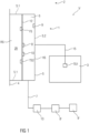
- the Figures 1 to 5 show schematically five exemplary embodiments of an electronic heat cost allocator 1, which can be used in a mold danger warning function.
- the electronic heat cost allocator 1 in all embodiments includes a first temperature sensor TS1 for detecting a radiator temperature of a radiator 3 arranged in a room 2, a second temperature sensor TS2 for detecting a wall temperature of a wall 4 of the room 2 or at least a room air temperature of the room 2 near the wall in one specified distance to wall 4 of room 2 and a humidity sensor FS. More precisely, they show Figures 1 to 5 each a device V with such an electronic heat cost allocator 1.
- this electronic heat cost allocator 1 can also be used in a room temperature monitoring function.
- the first temperature sensor TS1 is designed as a remote sensor, that is, arranged outside a housing 5 of a base unit 6 of the electronic heat cost allocator 1 and connected to the base unit 6 by a wireless or wired sensor connection 15.
- This first temperature sensor TS1 can be thermally coupled to the radiator 3 arranged in the room 2 or, as in the Figures 1 to 5 shown, thermally coupled.
- the second temperature sensor TS2 is arranged in the electronic heat cost allocator 1, in particular in its base unit 6, ie in and/or on its housing 5, and the electronic heat cost allocator 1 is designed such that the second temperature sensor TS2 is arranged by an arrangement of the electronic heat cost allocator 1, in particular the base unit 6, on the wall 4 of the room 2 on the wall 4 or at a predetermined, in particular as small as possible, distance from the wall 4 can be positioned or, as in the Figures 1 to 5 shown, positioned and can therefore be thermally coupled to the wall 4 or at least to the room air near the wall or, as in the Figures 1 to 5 shown is thermally coupled.
- the electronic heat cost allocator 1 advantageously comprises an evaluation unit 8, which is advantageously also integrated in the base unit 6, in particular in the housing 5 of which is arranged, advantageously a warning unit 9 for issuing a, in particular optical and/or acoustic, warning message and advantageously a communication unit 10 for wireless or wired communication with at least one external, in particular external to the heating cost allocator and in particular also external to the room and, for example, also external to the building, unit 13, 8 ', 9', in particular the reading unit 13 and / or the evaluation unit 8 'external to the heating cost allocator and / or the warning unit 9 external to the heating cost allocator ⁇ . i.e.
- the respective heat cost allocator-external unit 13, 8', 9' is arranged in particular outside the room 2 in which the radiator 3 and the electronic heat cost allocator 1 are arranged, in particular also outside a building in which this room 2 is arranged.
- the warning unit 9 and/or the communication unit 10 is/are expediently arranged in and/or on the base unit 6, in particular in and/or on its housing 5.
- the electronic heat cost allocator 1 is, for example, essentially designed as a conventional heat cost allocator, with the first temperature sensor TS1 being designed as a remote sensor for detecting the radiator temperature.
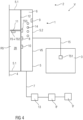
- the main difference to a conventional heat cost allocator is the additional humidity sensor FS and the warning unit 9 and an advantageously present third temperature sensor TS3, such as in the embodiments according to Figures 2 to 5 shown. The function of this third temperature sensor TS3 will be explained in more detail below.
- the electronic heat cost allocator 1 is designed such that the second temperature sensor TS2 is positioned in the area of a back RS of the heat cost allocator 1, in particular the base unit 6, or at least on a side of the main circuit board 12 facing the back RS.
- This back side RS is a mounting side which faces wall 4 during wall mounting.
- Wall mounting is advantageously carried out using a holder for the electronic heat cost allocator 1, in particular for the base unit 6, for example using a mounting plate.
- the embodiments of the electronic heat cost allocator 1 according to Figures 1 to 5 enable the operation of the electronic heat cost allocator 1 in the heat cost allocator function or in the mold risk warning function, but they also enable the operation of the electronic heat cost allocator 1, in particular at the same time, in the heat cost allocator function and in the mold risk warning function, in particular without the need for any conversion work regarding the design and arrangement of the electronic heat cost allocator 1 are required.
- the electronic heat cost allocator 1 does not have the third temperature sensor TS3, as in Figure 1 shown, the electronic heat cost allocator 1 works in the heat cost allocator function as a “single-sensor device”. Does the electronic heat cost allocator 1 have the third temperature sensor TS3, as in the Figures 2 to 5 shown, the electronic heat cost allocator 1 advantageously works in the heat cost allocator function as a “two-sensor device”.
- the third temperature sensor TS3 is intended to record the room air temperature in room 2 that is far from the wall. It is arranged at a distance from the second temperature sensor TS2, in particular arranged at a distance such that it can be positioned at a greater distance from the wall 4 due to the arrangement of the electronic heat cost allocator 1, in particular the base unit 6, on the wall 4 of the room 2 or, as in the Figures 2 to 5 shown, is positioned as the second temperature sensor TS2 and can therefore detect the room air temperature far from the wall, ie a room air temperature of room air that is further away from the wall 4 than the room air, whose room air temperature near the wall can be detected by the second temperature sensor TS2.
- the third temperature sensor TS3 is arranged in the area of the front side VS of the housing 5 of the base unit 6 in and/or on the housing 5, in particular in the area of the opening O of the housing 5 which is advantageously provided here, and the second temperature sensor TS2 is in the area the back RS of the housing 5 of the base unit 6 is arranged.
- the third temperature sensor TS3 is arranged in this way in the electronic heat cost allocator 1, in particular in its base unit 6, ie in its housing 5, preferably on the room-side side of the main circuit board 12 or on a sensor circuit board 11 oriented towards the room side, ie towards the front VS, and the Electronic heat cost allocator 1 is designed in such a way that the third temperature sensor TS3 is as far away as possible from the wall 4 by arranging the electronic heat cost allocator 1, in particular the base unit 6, on the wall 4 of the room 2, in particular with the smallest possible distance from the front VS of the housing 5 can be positioned or, as in the Figures 2 to 5 shown, is positioned and can therefore be thermally coupled well with the temperature of the room 2, in particular the room air away from the wall, or, as in the Figures 2 to 5 shown is thermally coupled.
- the housing 5 of the base unit 6 of the heat cost allocator 1 is advantageously provided with one or more housing openings 14 in order to allow air exchange with the room 2 and thus the thermal coupling of the third temperature sensor TS3 to improve the room air.
- the third temperature sensor TS3 is arranged on the sensor circuit board 11 and the second temperature sensor TS2 and the humidity sensor FS are each arranged on the side of the main circuit board 12 facing the back RS.
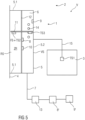
- the second temperature sensor TS2 and the humidity sensor FS are arranged on the sensor circuit board 11 and in this example are designed as a common sensor unit and the third temperature sensor TS3 is arranged on the main circuit board 12, more precisely on a side of the main circuit board 12, which is a front side VS of the electronic Heat cost allocator 1, in particular the base unit 6, faces, which faces an interior of the room 2.
- the housing 5 has one or more housing openings 14 in the area of the third temperature sensor TS3, as exemplified in Figure 4 shown.
- Both the second temperature sensor TS2 and the humidity sensor FS, which in this example are designed as a common sensor unit, as well as the third temperature sensor TS3 are arranged on the sensor circuit board 11, at opposite ends of the sensor circuit board 11, that is, the second temperature sensor TS2 on one of the back RS the end facing the housing 5 and the third temperature sensor TS3 at an end facing the front VS of the housing 5.
- the main circuit board 12 is advantageously arranged between them, ie the sensor circuit board 11 penetrates the main circuit board 12, as in Figure 5 shown.
- this deactivation does not occur despite the connected first temperature sensor TS1 designed as a remote sensor for detecting the radiator temperature, that is, in these embodiments of the electronic heat cost allocator 1, this deactivation is prevented when the first temperature sensor TS1 designed as a remote sensor is connected, so that in conventional heat cost allocators it functions as a radiator temperature sensor
- the internal temperature sensor provided can now be used as a second temperature sensor TS2 for detecting the wall temperature of the wall 4 of the room 2 or at least the room air temperature of the room 2 near the wall at a predetermined distance from the wall 4 of the room 2 by attaching the base unit 6 to the wall 4 of the room 2 is arranged as in the Figures 1 and 2 shown.
- this temperature sensor which is provided as a radiator temperature sensor in conventional heat cost allocators, as a second temperature sensor TS2 for detecting the wall temperature or at least the room air temperature near the wall.
- the humidity sensor must be provided for this and the evaluation and processing of sensor results from the sensors TS1, TS2, TS3, FS must be adjusted in order to enable the heating cost distribution function and the mold risk warning function.
- the second temperature sensor TS2 is arranged on a rear side of the main circuit board 12 facing the back side RS of the housing 5, as shown in FIGS Figures 1 and 2 shown, or on the sensor circuit board 11, as in the Figures 3 to 5 shown, here too the main circuit board 12 is arranged between the second temperature sensor TS2 and the third temperature sensor TS3.
- the main circuit board 12 acts as a thermal shield for the second temperature sensor TS2 against the room air temperature far from the wall and for the third temperature sensor TS3, if this is present, against the wall temperature and / or room air temperature near the wall, so that better temperature detection by means of the second temperature sensor TS2 and, If available, this is made possible by means of the third temperature sensor TS3.
- the radiator temperature of the radiator 3 is detected.
- the room air temperature of the room 2 remote from the wall is detected by means of the third temperature sensor TS3, which is thermally coupled to the room air away from the wall, in the embodiment according to Figure 1 by means of the detected radiator temperature and in the embodiments according to Figures 2 to 5 by means of the detected radiator temperature and the detected room air temperature away from the wall, an amount of heat emitted by the radiator 3 or an equivalent value for the amount of heat emitted by the radiator is determined.
- the radiator temperature of the radiator 3 is detected by means of the first temperature sensor TS1, which is thermally coupled to the radiator 3, and by means of the second temperature sensor TS2, which is thermally coupled to the wall 4 or at least to the room air near the wall, the wall temperature of the wall 4 of the room 2 or at least the room air temperature near the wall of the room 2 at the predetermined, in particular as small as possible, distance from the wall 4 of the room 2, the moisture, in particular the air humidity in the room 2, is detected by means of the humidity sensor FS and by means of the detected radiator temperature, the detected wall temperature or the room air temperature near the wall in the predetermined The distance from wall 4 of room 2 and the moisture detected determines the level of mold risk.
- the radiator temperature of the radiator 3 is detected by means of the first temperature sensor TS1, which is thermally coupled to the radiator 3, by means of which it is thermally coupled to the wall 4 or at least to the room air near the wall second temperature sensor TS2, the wall temperature of the wall 4 of the room 2 or at least the room air temperature of the room 2 near the wall is detected at the predetermined, in particular as small as possible, distance from the wall 4 of the room 2 and the moisture, in particular the air humidity in the room, is determined by means of the humidity sensor FS 2, recorded.
- the room air temperature of the room 2 remote from the wall is detected by means of the third temperature sensor TS3, which is thermally coupled to the room air away from the wall, in particular at a greater distance from the wall 4 of the room 2 than by the second temperature sensor TS2.
- the detected radiator temperature and in the embodiments according to Figures 2 to 5
- the amount of heat emitted by the radiator 3 or the equivalent value for the amount of heat emitted by the radiator 3 is determined by means of the room air temperature far from the wall detected by the third temperature sensor TS3.
- the level of mold risk is determined by means of the detected radiator temperature, the wall temperature or room air temperature near the wall at a predetermined distance from the wall 4 of the room 2 and the detected moisture using the second temperature sensor TS2.
- the radiator temperature of the radiator 3 is detected by means of the first temperature sensor TS1, which is thermally coupled to the radiator 3, by means of the first temperature sensor TS1, which is connected to the wall 4 or at least with the second temperature sensor TS2 thermally coupled to the room air close to the wall, the wall temperature of the wall 4 of the room 2 or at least the room air temperature of the room 2 close to the wall is detected at the predetermined, in particular as small as possible, distance from the wall 4 of the room 2, by means of the room air distant from the wall
- the thermally coupled third temperature sensor TS3 detects the room air temperature of the room 2 far from the wall, in particular at a greater distance from the wall 4 of the room 2 than by the second temperature sensor TS2, and the humidity, in particular the air humidity in the vicinity of the wall 4, is measured by means of the humidity sensor FS , recorded
- the amount of heat emitted by the radiator 3 or the equivalent value for the amount of heat emitted by the radiator 3 is determined by means of the detected radiator temperature and, for example, additionally by means of the room air temperature far from the wall detected by the third temperature sensor TS3.
- the level of mold risk is determined by means of the wall temperature or room air temperature near the wall detected by the second temperature sensor TS2 at a predetermined distance from the wall 4 of the room 2 and the detected moisture.
- the room temperature monitoring function is carried out and whether predetermined temperature thresholds are exceeded or undershot is monitored.
- the mold risk warning function includes the comparison of the radiator temperature, advantageously the room air temperature and the wall temperature, and the assessment derived therefrom as to whether the heating temperature and duration are suitable for delivering a room temperature that is suitable for reaching a predeterminable threshold value or for increasing the room temperature in this way that the wall temperature can rise as a result of the increased room temperature to such an extent that the moisture content of the air near the wall is reduced in such a way that the risk of mold formation is prevented or reduced becomes.
- the electronic heat cost allocator 1 can therefore be used as an alternative or in addition to the heat cost allocator function as a mold risk warning and for room temperature monitoring.
- the amount of heat emitted by the radiator 3 or the equivalent value for the amount of heat emitted by the radiator 3 and / or the level of the risk of mold and / or compliance with predetermined room temperature threshold values are / is determined in all embodiments shown in particular by means of, in particular in the base unit 6, i.e. H. in the housing 5, arranged, evaluation unit 8 of the electronic heat cost allocator 1 is determined.
- the electronic heat cost allocator 1, in particular its evaluation unit 8, is designed and set up accordingly for this purpose. An external evaluation is therefore not necessary.
- a warning message is generated, in particular by the evaluation unit 8, if the determined level of mold risk exceeds a predetermined limit value. This means that an immediate indication of the existing risk of mold can be provided.
- the generated warning message is output by the warning unit 9 and/or transmitted to the external readout unit 13 by means of the communication unit 10.
- people present in room 2 can be made aware of the risk of mold by means of the warning unit 9 and/or external responsible persons, for example a property management company, can be made aware of the risk of mold by means of the transmitted warning message.
- the detected radiator temperature is transmitted by means of the communication unit 10 to the at least one unit 13, 8 ', 9' external to the heat cost allocator, in particular to the external readout unit 13, and in particular also transmitted several times over time, in particular after a risk of mold has been determined, d. H. if the level of mold risk has exceeded the specified limit, and transmitted several times over time after a corresponding warning message has been issued.
- the property management should check whether and how the warning message regarding the risk of mold is responded to, in particular whether the radiator 3 is activated and thus the room 2 is heated sufficiently to reduce the risk of mold.
- the detected room air temperature of room 2 far from the wall and/or the detected wall temperature of wall 4 of room 2 or at least the room air temperature of room 2 close to the wall at a predetermined distance from wall 4 of room 2 and/or the detected temporal room temperature profile and/or or the recorded moisture measurement value can be transmitted in this way, for example to check whether corresponding reactions, in particular the activation or deactivation of the radiator 3, can be checked.
- Figures 1 to 5 show a housing 5 which is shell-shaped or lid-shaped, with a housing edge 5.1 being arranged flush on the wall 4 and, for example, being largely sealed, in particular media-tight, with the wall 4.
- the main circuit board 12 can be inserted into the housing 5, which is open in the direction of the wall 4, and arranged in such a way that a space ZR formed between the wall 4 and the main circuit board 12 is enclosed or encapsulated by the housing 5, in particular by the housing edge 5.1.
- the housing 5 is designed between the wall 4 and the main circuit board 12 to be essentially closed relative to the space 2.
- the humidity sensor FS and/or the second temperature sensor TS2 is/are arranged in an air volume that is open to the wall 4 and closed to the room 2.
- the housing 5 can be designed in such a way that it rests on the wall 4 with a minimal contact surface, for example only with the housing edge 5.1.
- a sensor aligned on the main circuit board 12 in the direction of the wall 4 and arranged in the space ZR such as the humidity sensor FS and/or the second temperature sensor TS2
- the minimum contact surface of the housing 5 on the wall 4 is particularly important in order to avoid mold formation on a damp wall 4 between the wall 4 and the support surface.
- the housing 5 can have openings 14 for ventilation on its cover side 5.2 and thus on the cover side 5.2 facing away from the wall 4 of the radiator, as in Figures 4 and 5 shown.
- Figure 6 shows an arrangement of the electronic heat cost allocator 1, in particular the base unit 6, not on the wall 4, but on the radiator 3.
- This shows another possible use of the electronic heat cost allocator 1 described here, in particular for its operation in the heat cost allocator function.
- the first temperature sensor TS1 which is designed as a remote sensor, is not required.
- the second temperature sensor TS2 which is actually intended to detect the wall temperature of a wall 4 of a room 2 or at least a room air temperature of the room 2 near the wall at a predetermined distance from the wall 4 of the room 2, can take over the function of the first temperature sensor TS1 here, namely the detection of the radiator temperature of the radiator 3 arranged in a room 2.
- the radiator temperature of the radiator 3 is then recorded by means of the second temperature sensor TS2, which is now thermally coupled to the radiator 3, and the amount of heat emitted by the radiator or the equivalent value for that emitted by the radiator amount of heat determined by means of the radiator temperature recorded in this way and, for example, the additionally recorded room air temperature of room 2 far from the wall.
Description
Die Erfindung betrifft einen elektronischen Heizkostenverteiler nach den Merkmalen des Oberbegriffs des Anspruchs 1 und ein Verfahren zu dessen Betrieb in einer Heizkostenverteilerfunktion und/oder in einer Schimmelgefahrwarnerfunktion.The invention relates to an electronic heat cost allocator according to the features of the preamble of claim 1 and a method for operating it in a heat cost allocator function and/or in a mold risk warning function.
Aus dem Stand der Technik ist, wie in der
In der
Der Erfindung liegt die Aufgabe zu Grunde, einen gegenüber dem Stand der Technik verbesserten elektronischen Heizkostenverteiler und ein gegenüber dem Stand der Technik verbessertes Verfahren zu dessen Betrieb in einer Heizkostenverteilerfunktion und/oder in einer Schimmelgefahrwarnerfunktion anzugeben.The invention is based on the object of specifying an electronic heat cost allocator that is improved over the prior art and a method for operating it in a heat cost allocator function and/or in a mold risk warning function that is improved over the prior art.
Die Aufgabe wird erfindungsgemäß gelöst durch einen elektronischen Heizkostenverteiler mit den Merkmalen des Anspruchs 1 und ein Verfahren zu dessen Betrieb in einer Heizkostenverteilerfunktion und/oder in einer Schimmelgefahrwarnerfunktion mit den Merkmalen des Anspruchs 9.The object is achieved according to the invention by an electronic heat cost allocator with the features of claim 1 and a method for operating it in a heat cost allocator function and / or in a mold risk warning function with the features of
Vorteilhafte Ausgestaltungen der Erfindung sind Gegenstand der Unteransprüche.Advantageous embodiments of the invention are the subject of the subclaims.
Ein elektronischer Heizkostenverteiler umfasst einen ersten Temperatursensor zur Erfassung einer Heizkörpertemperatur eines in einem Raum angeordneten Heizkörpers, einen zweiten Temperatursensor zur Erfassung einer Wandtemperatur einer Wand des Raums oder zumindest einer durch die Wandtemperatur erheblich beeinflussten wandnahen Raumlufttemperatur des Raums in einem vorgegebenen, insbesondere möglichst geringen, Abstand zur Wand des Raums, und einen Feuchtesensor. Mittels des Feuchtesensors ist insbesondere eine wandnahe Raumfeuchte erfassbar, wenn der elektronische Heizkostenverteiler an der Wand angeordnet ist, insbesondere montiert ist.An electronic heat cost allocator comprises a first temperature sensor for detecting a radiator temperature of a radiator arranged in a room, a second temperature sensor for detecting a wall temperature of a wall of the room or at least a room air temperature of the room near the wall that is significantly influenced by the wall temperature at a predetermined distance, in particular as small as possible to the wall of the room, and a humidity sensor. By means of the humidity sensor, room humidity near the wall can be detected in particular when the electronic heat cost allocator is arranged on the wall, in particular when it is mounted.
Erfindungsgemäß ist der erste Temperatursensor als ein Fernfühler ausgebildet, d. h. außerhalb eines Gehäuses einer Basiseinheit des elektronischen Heizkostenverteilers angeordnet und mit dieser durch eine kabellose oder kabelgebundene Sensoranbindung verbunden, und mit dem im Raum angeordneten Heizkörper thermisch koppelbar oder gekoppelt, und der zweite Temperatursensor ist derart im elektronischen Heizkostenverteiler, erfindungsgemäß in der Basiseinheit, d. h. in und/oder am Gehäuse, angeordnet und der elektronische Heizkostenverteiler, insbesondere die Basiseinheit, ist derart ausgebildet, dass der zweite Temperatursensor durch eine Anordnung des elektronischen Heizkostenverteilers, insbesondere der Basiseinheit, beispielsweise mittels einer entsprechenden Halterung, an der Wand des Raumes an der Wand oder in einem vorgegebenen Abstand zur Wand positionierbar oder positioniert ist, wodurch der zweite Temperatursensor mit der Wand oder zumindest mit der wandnahen Raumluft thermisch koppelbar bzw. gekoppelt ist. Der Feuchtesensor ist erfindungsgemäß ebenfalls ein Bestandteil der Basiseinheit, d. h. im und/oder am Gehäuse der Basiseinheit angeordnet, kann aber in nicht erfindungsgemäßen anderen Ausführungsformen beispielsweise auch als ein Fernfühler ausgebildet sein. Der Feuchtesensor ist, wenn er in der Basiseinheit angeordnet ist, vorteilhafterweise derart im elektronischen Heizkostenverteiler, insbesondere in der Basiseinheit, d. h. in oder am Gehäuse, angeordnet und der elektronische Heizkostenverteiler, insbesondere die Basiseinheit, ist derart ausgebildet, dass der Feuchtesensor durch eine Anordnung des elektronischen Heizkostenverteilers, insbesondere der Basiseinheit, beispielsweise mittels einer entsprechenden Halterung, an der Wand des Raumes vorteilhafterweise an der Wand oder in einem vorgegebenen Abstand zur Wand positionierbar oder positioniert ist, wodurch der Feuchtesensor mit der Wand oder zumindest mit der wandnahen Raumluft klimatisch, insbesondere bezüglich Feuchtigkeit, gut koppelbar bzw. gekoppelt ist. Die Sensoranbindung des ersten Temperatursensors zur Basiseinheit ist beispielsweise als eine Anschlussleitung zum Messen eines Sensorwiderstandes des ersten Temperatursensors ausgebildet, kann in anderen Ausführungsformen aber beispielsweise auch als eine digitale Busanschlussleitung oder als eine drahtlose Sensoranbindung ausgebildet sein.According to the invention, the first temperature sensor is designed as a remote sensor, ie arranged outside a housing of a base unit of the electronic heat cost allocator and connected to it by a wireless or wired sensor connection, and can be thermally coupled or coupled to the radiator arranged in the room, and the second temperature sensor is in this way electronic heat cost allocator, according to the invention arranged in the base unit, ie in and/or on the housing, and the electronic heat cost allocator, in particular the base unit, is designed such that the second temperature sensor is arranged by an arrangement of the electronic heat cost allocator, in particular the base unit, for example by means of a corresponding holder , can be positioned on the wall of the room on the wall or at a specified distance from the wall or is positioned, whereby the second temperature sensor can be thermally coupled or coupled to the wall or at least to the room air near the wall. According to the invention, the humidity sensor is also a component of the base unit, ie arranged in and/or on the housing of the base unit, but in other embodiments not according to the invention can also be designed, for example, as a remote sensor. The humidity sensor, if it is arranged in the base unit, is advantageously arranged in the electronic heat cost allocator, in particular in the base unit, ie in or on the housing, and the electronic heat cost allocator, in particular the base unit, is designed such that the humidity sensor is arranged by an arrangement of the Electronic heat cost allocator, in particular the base unit, can be positioned or positioned, for example by means of a corresponding holder, on the wall of the room, advantageously on the wall or at a predetermined distance from the wall, whereby the humidity sensor is climatically connected to the wall or at least to the room air near the wall, in particular with regard to Moisture, can be easily coupled or coupled. The sensor connection of the first temperature sensor to the base unit is designed, for example, as a connection line for measuring a sensor resistance of the first temperature sensor, but in other embodiments can also be designed, for example, as a digital bus connection line or as a wireless sensor connection.
Unter wandnah ist insbesondere ein Abstand zur Wand von maximal 30 mm, insbesondere von maximal 25 mm, insbesondere von maximal 20 mm, insbesondere von maximal 15 mm, bevorzugt von maximal 10 mm, besonders bevorzugt von maximal 5 mm, zu verstehen. Innerhalb dieses Abstands zur Wand ist der betreffende Sensor, insbesondere der zweiten Temperatursensor und/oder der Feuchtesensor, zweckmäßigerweise angeordnet, wenn der elektronische Heizkostenverteiler, insbesondere dessen Basiseinheit, an der Wand angeordnet ist, insbesondere montiert ist.Close to the wall means in particular a distance to the wall of a maximum of 30 mm, in particular a maximum of 25 mm, in particular a maximum of 20 mm, in particular a maximum of 15 mm, preferably a maximum of 10 mm, particularly preferably a maximum of 5 mm. The sensor in question, in particular the second temperature sensor and/or the humidity sensor, is expediently arranged within this distance from the wall if the electronic heat cost allocator, in particular its base unit, is arranged, in particular mounted, on the wall.
Unter wandnah ist alternativ oder zusätzlich insbesondere zu verstehen, dass der betreffende Sensor, insbesondere der zweite Temperatursensor und/oder der Feuchtesensor, im Heizkostenverteiler, insbesondere in dessen Basiseinheit, näher an einer der Wand zugewandten Rückseite als an einer der Rückseite gegenüberliegenden und dem Raum zugewandten Vorderseite angeordnet ist, insbesondere um ein Mehrfaches näher an der Rückseite als an der Vorderseite.Alternatively or additionally, close to the wall means in particular that the sensor in question, in particular the second temperature sensor and/or the humidity sensor, in the heat cost allocator, in particular in its base unit, is closer to a back side facing the wall than to a back side opposite the back side and the front facing the room is arranged, in particular several times closer to the back than to the front.
Durch diese erfindungsgemäße Ausbildung des elektronischen Heizkostenverteilers, insbesondere durch den als Fernfühler ausgebildeten ersten Temperatursensor zur Heizkörpertemperaturerfassung, den zusätzlichen Feuchtesensor, insbesondere zur Erfassung des wandnahen Luftfeuchtegehaltes, und den zweiten Temperatursensor zur Erfassung der Wandtemperatur oder der wandnahen Raumlufttemperatur in einem vorgegebenen, möglichst kleinen, Abstand zur Wand, wird mittels dieses elektronischen Heizkostenverteilers eine Schimmelgefahrermittlung und somit einer Schimmelgefahrwarnung ermöglicht. Der elektronische Heizkostenverteiler kann somit, beispielsweise alternativ oder zusätzlich zur Verwendung in seiner Heizkostenverteilerfunktion, auch als Schimmelwarner verwendet werden, d. h. in der Schimmelgefahrwarnerfunktion. Die Schimmelgefahr kann beispielsweise ermittelt werden, indem in Abhängigkeit von einer gemessenen relativen Feuchte der Taupunkt berechnet wird und festgestellt wird, ob die ermittelte aktuelle Wandtemperatur oder die ermittelte durch die Wandtemperatur erheblich beeinflusste wandnahe Raumlufttemperatur des Raums in einem vorgegebenen, insbesondere möglichst geringen, Abstand zur Wand des Raums unterhalb der Taupunkttemperatur liegt und somit die Gefahr einer Kondensation auf einer Wandoberfläche der Wand vorliegt und damit eine wichtige Voraussetzung für Schimmelbildung vorhanden ist. Die Gefahr der Schimmelbildung, insbesondere an Wänden des Raums, besteht insbesondere dann, wenn eine geringe Wandtemperatur und eine hohe Feuchtigkeit im Raum vorliegen und wenn der Raum nicht beheizt wird. Dies kann mittels des ersten und zweiten Temperatursensors und des Feuchtesensors ermittelt werden. Hierfür sind beispielsweise nur geringe Modifikationen eines herkömmlichen elektronischen Heizkostenverteilers erforderlich, um den erfindungsgemäßen elektronischen Heizkostenverteiler auszubilden.Through this inventive design of the electronic heat cost allocator, in particular through the first temperature sensor designed as a remote sensor for detecting the radiator temperature, the additional humidity sensor, in particular for detecting the air moisture content near the wall, and the second temperature sensor for detecting the wall temperature or the room air temperature near the wall at a predetermined distance that is as small as possible to the wall, this electronic heat cost allocator enables a mold risk determination and thus a mold risk warning. The electronic heat cost allocator can therefore also be used as a mold alarm, for example as an alternative or in addition to its use in its heat cost allocator function, i.e. H. in the mold danger warning function. The risk of mold can be determined, for example, by calculating the dew point depending on a measured relative humidity and determining whether the determined current wall temperature or the determined room air temperature of the room near the wall, which is significantly influenced by the wall temperature, is at a predetermined, in particular as small as possible, distance from the Wall of the room is below the dew point temperature and there is therefore a risk of condensation on a wall surface of the wall and therefore an important prerequisite for mold formation. The risk of mold formation, especially on the walls of the room, exists particularly if there is a low wall temperature and high humidity in the room and if the room is not heated. This can be determined using the first and second temperature sensors and the humidity sensor. For this purpose, for example, only minor modifications to a conventional electronic heat cost allocator are required in order to form the electronic heat cost allocator according to the invention.
Als zweiter Temperatursensor, welcher bei der hier beschriebenen Lösung zur Erfassung der Wandtemperatur der Wand des Raums oder zumindest der durch die Wandtemperatur erheblich beeinflussten wandnahen Raumlufttemperatur des Raums in einem vorgegebenen, insbesondere möglichst geringen, Abstand zur Wand des Raums vorgesehen ist, kann beispielsweise ein herkömmlicher Heizkörpertemperatursensor verwendet werden, welcher in einem herkömmlichen Heizkostenverteiler zur Erfassung der Heizkörpertemperatur vorgesehen wäre. Dies wird durch eine entsprechende Anordnung eines solchen Temperatursensors im elektronischen Heizkostenverteiler, d. h. in der Basiseinheit, und/oder durch eine entsprechende Anordnung der Basiseinheit an der Wand ermöglicht.As a second temperature sensor, which in the solution described here is used to detect the wall temperature of the wall of the room or at least the room air temperature of the room near the wall, which is significantly influenced by the wall temperature, at a predetermined, in particular as small as possible, distance from the wall of the Room is provided, for example a conventional radiator temperature sensor can be used, which would be provided in a conventional heat cost allocator to record the radiator temperature. This is made possible by a corresponding arrangement of such a temperature sensor in the electronic heat cost allocator, ie in the base unit, and/or by a corresponding arrangement of the base unit on the wall.
Alternativ kann als zweiter Temperatursensor, welcher bei der hier beschriebenen Lösung zur Erfassung der Wandtemperatur der Wand des Raums oder zumindest der durch die Wandtemperatur erheblich beeinflussten wandnahen Raumlufttemperatur des Raums in einem vorgegebenen, insbesondere möglichst geringen, Abstand zur Wand des Raums vorgesehen ist, auch der herkömmliche Raumlufttemperatursensor verwendet werden, welcher in einem herkömmlichen Heizkostenverteiler zur Erfassung der wandfernen Raumlufttemperatur vorgesehen wäre.Alternatively, as a second temperature sensor, which in the solution described here is provided for detecting the wall temperature of the wall of the room or at least the room air temperature of the room near the wall, which is significantly influenced by the wall temperature, at a predetermined, in particular as small as possible, distance from the wall of the room, the Conventional room air temperature sensor can be used, which would be provided in a conventional heating cost allocator to record the room air temperature far from the wall.
Üblicherweise ist ein solcher herkömmlicher Raumlufttemperatursensor bei einem herkömmlichen elektronischen Heizkostenverteiler derart angeordnet, dass er möglichst gut eine Gehäusetemperatur und damit die wandferne Raumlufttemperatur erfassen kann. Für einen Schimmelgefahrwarner ist jedoch die Wandtemperatur maßgeblich. Um diesen als herkömmlichen Raumtemperatursensor ausgebildeten zweiten Temperatursensor daher mit der Wand thermisch zu kontaktieren oder zumindest in den vorgegebenen, insbesondere möglichst geringen, Abstand zur Wand zu bringen, kann beispielsweise vorgesehen sein, diesen herkömmlichen Raumlufttemperatursensor innerhalb der Basiseinheit entsprechend anders zu positionieren, insbesondere derart, dass dieser herkömmliche Raumlufttemperatursensor nun einer Rückseite der Basiseinheit zugewandt ist und somit durch Anordnen der Basiseinheit mit ihrer Rückseite an der Wand mit dieser Wand oder zumindest mit der wandnahen Raumluft thermisch koppelbar ist. Dies kann beispielsweise erfolgen, indem dieser Temperatursensor auf einer der Rückseite der Basiseinheit zugewandten Rückseite einer Hauptleiterplatte der Basiseinheit angeordnet wird oder zusammen mit der Hauptleiterplatte, auf welcher er angeordnet ist, um 180°, insbesondere um die Längsachse, gedreht wird. Alternativ kann dies beispielsweise erfolgen, indem eine Sensorleiterplatte, auf welcher dieser Temperatursensor angeordnet ist, in der Basiseinheit um 180° gedreht und an der Rückseite der Hauptleiterplatte angeordnet wird oder indem diese Sensorleiterplatte zusammen mit der Hauptleiterplatte um 180°, insbesondere um die Längsachse der Hauptleiterplatte, gedreht wird, so dass nun das Ende der Sensorleiterplatte mit dem nun den zweiten Temperatursensor bildenden Temperatursensor im Bereich der Rückseite der Basiseinheit positioniert ist.Typically, such a conventional room air temperature sensor is arranged in a conventional electronic heat cost allocator in such a way that it can detect a housing temperature and thus the room air temperature away from the wall as well as possible. However, the wall temperature is crucial for a mold danger warning. In order to thermally contact this second temperature sensor, which is designed as a conventional room temperature sensor, with the wall or at least to bring it into the predetermined, in particular as small as possible, distance from the wall, it can be provided, for example, to position this conventional room air temperature sensor differently within the base unit, in particular in such a way that that this conventional room air temperature sensor now faces a back of the base unit and can therefore be thermally coupled to this wall or at least to the room air near the wall by arranging the base unit with its back on the wall. This can be done, for example, by arranging this temperature sensor on a back side of a main circuit board of the base unit facing the back of the base unit or by rotating it through 180°, in particular around the longitudinal axis, together with the main circuit board on which it is arranged. Alternatively, this can be done, for example, by placing a sensor circuit board on which this temperature sensor is arranged in the Base unit is rotated by 180° and arranged on the back of the main circuit board or by rotating this sensor circuit board together with the main circuit board by 180°, in particular around the longitudinal axis of the main circuit board, so that the end of the sensor circuit board is now connected to the temperature sensor which now forms the second temperature sensor is positioned in the area of the back of the base unit.
Der Feuchtesensor ist ein zusätzlicher Sensor, der in einem herkömmlichen Heizkostenverteiler zur Erfassung der Heizkörpertemperatur nicht vorgesehen ist und in dem erfindungsgemäßen Heizkostenverteiler, insbesondere in dessen Basiseinheit, zusätzlich vorhanden ist und durch eine entsprechende Anordnung im elektronischen Heizkostenverteiler, insbesondere auf der der Raumseite gegenüberliegenden Seite der Hauptleiterplatte, d. h. in der Basiseinheit, und/oder durch eine entsprechende Anordnung der Basiseinheit an der Wand zur Erfassung der Wandfeuchte der Wand des Raums oder zumindest der wandnahen Feuchte des Raums im vorgegebenen, möglichst geringen, Abstand zur Wand des Raums verwendet werden kann.The humidity sensor is an additional sensor that is not provided in a conventional heat cost allocator for detecting the radiator temperature and is additionally present in the heat cost allocator according to the invention, in particular in its base unit, and is provided by a corresponding arrangement in the electronic heat cost allocator, in particular on the side opposite the room side main circuit board, i.e. H. in the base unit, and/or by a corresponding arrangement of the base unit on the wall for detecting the wall moisture of the wall of the room or at least the moisture of the room near the wall at the predetermined, as small as possible, distance from the wall of the room.
In einer möglichen Ausführungsform umfasst der elektronische Heizkostenverteiler einen dritten Temperatursensor zur Erfassung der wandfernen Raumlufttemperatur des Raums, welcher vom zweiten Temperatursensor beabstandet angeordnet ist, insbesondere derart beabstandet angeordnet ist, dass er durch die Anordnung des elektronischen Heizkostenverteilers, insbesondere der Basiseinheit, an der Wand des Raumes in einem größeren Abstand zur Wand positionierbar oder positioniert ist als der zweite Temperatursensor und somit die wandferne Raumlufttemperatur erfassen kann, d. h. eine Raumlufttemperatur von Luft, die weiter entfernt von der Wand ist als die Luft, deren wandnahe Raumlufttemperatur vom zweiten Temperatursensor erfasst werden kann. Insbesondere dadurch wird es ermöglicht, den elektronischen Heizkostenverteiler gleichzeitig für die Heizkostenverteilerfunktion und für die Schimmelgefahrwarnerfunktion zu verwenden, da sowohl die Wandtemperatur oder die wandnahe Raumlufttemperatur im vorgegebenen geringen Abstand zur Wand erfasst werden kann, welche für die Schimmelgefahrwarnerfunktion erforderlich ist, als auch die wandferne Raumlufttemperatur des Raums in größerem Abstand zur Wand, welche somit nicht oder wesentlich geringer durch die Wandtemperatur beeinflusst ist, erfasst werden kann.In a possible embodiment, the electronic heat cost allocator comprises a third temperature sensor for detecting the room air temperature of the room remote from the wall, which is arranged at a distance from the second temperature sensor, in particular is arranged at a distance such that it is due to the arrangement of the electronic heat cost allocator, in particular the base unit, on the wall of the Room can be positioned or positioned at a greater distance from the wall than the second temperature sensor and can therefore detect the room air temperature far from the wall, ie a room air temperature of air that is further away from the wall than the air whose room air temperature near the wall can be detected by the second temperature sensor. In particular, this makes it possible to use the electronic heat cost allocator simultaneously for the heat cost allocator function and for the mold risk warning function, since both the wall temperature or the room air temperature near the wall can be recorded at the predetermined short distance from the wall, which is required for the mold risk warning function, as well as the room air temperature away from the wall of the room at a greater distance from the wall, which is therefore not or significantly less influenced by the wall temperature.
Der Feuchtesensor und der zweite Temperatursensor sind insbesondere auf der der Rückseite und/oder Montageseite des elektronischen Heizkostenverteilers, insbesondere der Basiseinheit, zugewandten Seite der Hauptleiterplatte oder im Bereich dieser Seite der Hauptleiterplatte im elektronischen Heizkostenverteiler, insbesondere in der Basiseinheit, angeordnet und der elektronische Heizkostenverteiler, insbesondere die Basiseinheit, ist insbesondere derart ausgebildet, dass der Feuchtesensor und der zweite Temperatursensor durch eine Anordnung des elektronischen Heizkostenverteilers, insbesondere der Basiseinheit, an der Wand des Raumes an der Wand oder in einem vorgegebenen Abstand zur Wand positionierbar oder positioniert sind und damit klimatisch gut an die Wandverhältnisse angekoppelt sind.The humidity sensor and the second temperature sensor are arranged in particular on the side of the main circuit board facing the back and/or mounting side of the electronic heat cost allocator, in particular the base unit, or in the area of this side of the main circuit board in the electronic heat cost allocator, in particular in the base unit, and the electronic heat cost allocator, in particular the base unit, is in particular designed in such a way that the humidity sensor and the second temperature sensor can be positioned or are positioned by an arrangement of the electronic heat cost allocator, in particular the base unit, on the wall of the room on the wall or at a predetermined distance from the wall and are therefore climatically good are coupled to the wall conditions.
Der dritte Temperatursensor ist, wenn vorhanden, insbesondere derart im elektronischen Heizkostenverteiler, insbesondere in der Basiseinheit, an der Vorderseite und/oder Raumseite oder in deren Bereich angeordnet und der elektronische Heizkostenverteiler, insbesondere die Basiseinheit, derart ausgebildet, dass der dritte Temperatursensor gut an die wandferne Raumlufttemperatur angekoppelt ist.The third temperature sensor, if present, is arranged in particular in the electronic heat cost allocator, in particular in the base unit, on the front and/or side of the room or in the area thereof, and the electronic heat cost allocator, in particular the base unit, is designed such that the third temperature sensor is well connected to the room air temperature away from the wall is coupled.
Der erste Temperatursensor ist, wie bereits erwähnt, als ein Fernfühler ausgebildet und, insbesondere bei einer Anordnung des Heizkostenverteilers, insbesondere der Basiseinheit, an der Wand, mit dem im Raum angeordneten Heizkörper thermisch koppelbar oder gekoppelt.As already mentioned, the first temperature sensor is designed as a remote sensor and, in particular when the heat cost allocator, in particular the base unit, is arranged on the wall, can be thermally coupled or coupled to the radiator arranged in the room.
Das Gehäuse des elektronischen Heizkostenverteilers, genauer gesagt der Basiseinheit des elektronischen Heizkostenverteilers, ist vorteilhafterweise im Wesentlichen offen gegenüber der Wand des Heizkörpers. Beispielsweise ist das Gehäuse schalenförmig oder deckelförmig ausgebildet, wobei der Gehäuserand bündig auf der Wand angeordnet ist und beispielsweise dicht mit dieser abschließt. Die Hauptleiterplatte kann dabei in dem in Richtung der Wand offenen Gehäuse eingesetzt und derart angeordnet sein, dass ein zwischen der Wand und der Hauptleiterplatte gebildeter Zwischenraum vom Gehäuse umschlossen oder eingekapselt ist. Mit anderen Worten: Das Gehäuse ist zwischen Wand und Hauptleiterplatte im Wesentlichen geschlossen gegenüber dem Raum ausgebildet. Das Gehäuse kapselt somit den Zwischenraum zwischen Wand und Hauptleiterplatte gegenüber der Umgebung und damit dem Raum ab oder ummantelt diesen. Die Hauptleiterplatte dient dabei vorteilhafterweise ebenfalls zum Abschließen dieses Zwischenraums gegenüber der Umgebung und damit gegenüber dem Raum. Sie schirmt diesen Zwischenraum insbesondere nach vorn, in Richtung der Vorderseite des Gehäuses und somit in Richtung des Raums ab.The housing of the electronic heat cost allocator, more precisely the base unit of the electronic heat cost allocator, is advantageously essentially open to the wall of the radiator. For example, the housing is shell-shaped or lid-shaped, with the housing edge being arranged flush on the wall and, for example, sealing tightly with it. The main circuit board can be inserted into the housing that is open in the direction of the wall and arranged in such a way that a gap formed between the wall and the main circuit board is enclosed or encapsulated by the housing. In other words: The housing is essentially closed to the room between the wall and the main circuit board. The housing thus encapsulates the space between the wall and the main circuit board from the surroundings and thus the room or encases it. The main circuit board advantageously also serves to close off this gap from the environment and thus from the room. It shields this gap in particular from the front, towards the front of the housing and thus towards the room.
Darüber hinaus kann das Gehäuse derart ausgebildet sein, dass es mit minimaler Auflagefläche, beispielsweise nur mit dem Gehäuserand, auf der Wand aufliegt. Hierdurch ist ein auf der Hauptleiterplatte in Richtung der Wand ausgerichteter und im Zwischenraum angeordneter Sensor oder ein auf der Sensorleiterplatte und im Zwischenraum angeordneter Sensor, wie ein Feuchte- oder Temperatursensor, insbesondere der zweite Temperatursensor und/oder der Feuchtesensor, thermisch mit der Wand koppelbar, insbesondere direkt oder indirekt über Luftaustausch mit der Wand thermisch koppelbar. Durch die im Wesentlichen gegenüber dem Raum geschlossene Ausbildung des Gehäuses zwischen Wand und Hauptleiterplatte kann die natürliche Konvektion an der Wand nicht durch das Volumen unterhalb der Hauptleiterplatte erfolgen oder ist zumindest sehr stark eingeschränkt.In addition, the housing can be designed in such a way that it rests on the wall with a minimal contact surface, for example only with the edge of the housing. As a result, a sensor aligned on the main circuit board in the direction of the wall and arranged in the gap or a sensor arranged on the sensor circuit board and in the gap, such as a humidity or temperature sensor, in particular the second temperature sensor and / or the humidity sensor, can be thermally coupled to the wall, In particular, it can be thermally coupled to the wall directly or indirectly via air exchange. Due to the design of the housing between the wall and the main circuit board, which is essentially closed to the room, the natural convection on the wall cannot take place through the volume below the main circuit board or is at least very severely restricted.
Beispielsweise ist eine Rückseite des Gehäuses, welche die Montageseite des elektronischen Heizkostenverteilers, insbesondere der Basiseinheit, bildet, entsprechend offen gegen die Wand und optional geschlossen gegenüber dem Raum unterhalb der Hauptleiterplatte ausgebildet. Die minimale Auflagefläche ist derart bemessen, dass der elektronische Heizkostenverteiler, insbesondere die Basiseinheit, an der Wand montierbar ist, beispielsweise mittels einer Wandhalterung, und derart offen ist, dass eine gute klimatische und/oder thermische Kopplung des zweiten Temperatursensors und des Feuchtesensors an die Wand ermöglicht ist. Eine minimale Auflagefläche auf der Wand ist vor allem wichtig, um eine Schimmelbildung auf einer feuchten Wand zwischen Wand und Auflagefläche zu vermeiden. Für eine hinreichende Durchlüftung kann das Gehäuse auf der Deckseite und damit auf der von der Wand abgewandten Seite, d. h. insbesondere auf der dem Raum zugewandten Seite, Öffnungen zum Belüften aufweisen.For example, a rear side of the housing, which forms the mounting side of the electronic heat cost allocator, in particular the base unit, is designed to be correspondingly open towards the wall and optionally closed towards the space below the main circuit board. The minimum support surface is dimensioned such that the electronic heat cost allocator, in particular the base unit, can be mounted on the wall, for example by means of a wall bracket, and is open in such a way that a good climatic and/or thermal coupling of the second temperature sensor and the humidity sensor to the wall is possible. A minimal contact surface on the wall is particularly important in order to avoid mold formation on a damp wall between the wall and the support surface. For sufficient ventilation, the housing can have openings for ventilation on the cover side and thus on the side facing away from the wall, ie in particular on the side facing the room.
Der elektronische Heizkostenverteiler kann des Weiteren alternativ oder zusätzlich zur Verwendung in seiner Heizkostenverteilerfunktion und/oder Schimmelgefahrwarnerfunktion auch in einer Raumtemperaturüberwachungsfunktion eingesetzt werden, um insbesondere einen zeitlichen Verlauf der wandfernen Raumlufttemperatur mittels des dritten Temperatursensors zu überwachen und gegebenenfalls mittels einer Warneinheit eine Unterschreitung einer vorgebbaren minimalen Raumlufttemperatur oder eine Überschreitung einer vorgebaren maximalen Raumlufttemperatur zu signalisieren. Hierzu sind im Allgemeinen nur geringe Modifikationen eines herkömmlichen Heizkostenverteilers notwendig.The electronic heat cost allocator can also be used, alternatively or in addition to its use in its heat cost allocator function and/or mold risk warning function, in a room temperature monitoring function, in particular to monitor a time course of the room air temperature away from the wall by means of the third temperature sensor and, if necessary, by means of a warning unit, if the room air temperature falls below a predeterminable minimum or to signal that a predetermined maximum room air temperature has been exceeded. This generally only requires minor modifications to a conventional heat cost allocator.
Des Weiteren kann aus dem Vergleich der Heizkörpertemperatur, der wandfernen Raumlufttemperatur und der Wandtemperatur der Wand des Raums oder zumindest der durch die Wandtemperatur erheblich beeinflussten wandnahen Raumlufttemperatur des Raums im vorgegebenen, insbesondere möglichst geringen, Abstand zur Wand des Raums abgeleitet werden, ob die Heiztemperatur und -dauer dazu geeignet sind, eine Raumlufttemperatur zu liefern, die einen vorgebbaren Schwellwert zu erreichen geeignet ist bzw. die Raumlufttemperatur so zu erhöhen, dass diese Wandtemperatur in Folge der erhöhten Raumlufttemperatur so ansteigen kann, dass der Feuchtegehalt der wandnahen Raumluft so verringert wird, dass die Schimmelbildungsgefahr verhindert oder vermindert wird.Furthermore, from the comparison of the radiator temperature, the room air temperature away from the wall and the wall temperature of the wall of the room or at least the room air temperature of the room near the wall, which is significantly influenced by the wall temperature, at the specified, in particular as small as possible, distance from the wall of the room, it can be derived whether the heating temperature and - Duration are suitable for delivering a room air temperature that is suitable for reaching a predeterminable threshold value or for increasing the room air temperature so that this wall temperature can increase as a result of the increased room air temperature in such a way that the moisture content of the room air near the wall is reduced so that the risk of mold formation is prevented or reduced.
Der zweite Temperatursensor, welcher bei der hier beschriebenen Lösung zur Erfassung einer Wandtemperatur einer Wand des Raums oder zumindest einer durch die Wandtemperatur erheblich beeinflussten wandnahen Raumlufttemperatur des Raums in einem vorgegebenen, insbesondere möglichst geringen, Abstand zur Wand des Raums vorgesehen ist, ist in einer möglichen Ausführungsform als ein im elektronischen Heizkostenverteiler, d. h. in der Basiseinheit, integrierter Heizkörpertemperatursensor ausgebildet, welcher zur Erfassung der Heizkörpertemperatur bei am Heizkörper angeordnetem Heizkostenverteiler und nicht verwendetem ersten Temperatursensor vorgesehen ist. Ein solcher integrierter Heizkörpertemperatursensor wird bei einem herkömmlichen elektronischen Heizkostenverteiler bei Verwendung eines als Fernfühler ausgebildeten Heizkörpertemperatursensors deaktiviert. Dies wird bei der hier beschriebenen Lösung jedoch nicht gemacht, d. h. dieser interne Heizkörpertemperatursensor wird, obwohl zusätzlich der Fernfühler vorhanden ist, nicht deaktiviert, sondern er wird nun als zweiter Temperatursensor zur Erfassung der Wandtemperatur oder zumindest der durch die Wandtemperatur erheblich beeinflussten wandnahen Raumlufttemperatur des Raums im vorgegebenen, insbesondere möglichst geringen, Abstand zur Wand des Raums verwendet. Dadurch kann die Basiseinheit auf gleiche oder ähnliche Weise an der Wand angeordnet werden, wie sie als elektronischer Heizkostenverteiler ohne Fernfühler am Heizkörper angeordnet werden würde, beispielsweise mit einer entsprechenden Montageplatte, und nun mittels des zweiten Temperatursensors die Wandtemperatur der Wand des Raums oder zumindest die durch die Wandtemperatur erheblich beeinflusste wandnahe Raumlufttemperatur des Raums im vorgegebenen, insbesondere möglichst geringen, Abstand zur Wand des Raums erfassen. Es ist somit nur eine sehr geringe Modifikation eines herkömmlichen elektronischen Heizkostenverteilers erforderlich, um dies und somit die Schimmelgefahrwarnerfunktion und, insbesondere auch gleichzeitig, weiterhin die Heizkostenverteilerfunktion zu ermöglichen. Hierfür sind insbesondere der zusätzliche Feuchtesensor und der als Fernfühler ausgebildete erste Temperatursensor zur Erfassung der Heizkörpertemperatur erforderlich. Des Weiteren ist beispielsweise eine entsprechend angepasste Auswertung von Sensorergebnissen der Sensoren des Heizkostenverteilers erforderlich.The second temperature sensor, which in the solution described here is provided for detecting a wall temperature of a wall of the room or at least a room air temperature of the room near the wall that is significantly influenced by the wall temperature, at a predetermined, in particular as small as possible, distance from the wall of the room, is in a possible Embodiment designed as a radiator temperature sensor integrated in the electronic heat cost allocator, ie in the base unit, which is provided for detecting the radiator temperature when the heat cost allocator is arranged on the radiator and the first temperature sensor is not used. Such an integrated radiator temperature sensor is deactivated in a conventional electronic heat cost allocator when using a radiator temperature sensor designed as a remote sensor. However, this is not done with the solution described here, i.e. this internal one Although the remote sensor is also present, the radiator temperature sensor is not deactivated, but is now used as a second temperature sensor to record the wall temperature or at least the room air temperature of the room near the wall, which is significantly influenced by the wall temperature, at the specified, in particular as small as possible, distance from the wall of the room. This means that the base unit can be arranged on the wall in the same or similar way as it would be arranged on the radiator as an electronic heat cost allocator without a remote sensor, for example with a corresponding mounting plate, and now by means of the second temperature sensor the wall temperature of the wall of the room or at least that through the wall temperature is significantly influenced by recording the room air temperature of the room near the wall at a specified, in particular as small as possible, distance from the wall of the room. Therefore, only a very small modification of a conventional electronic heat cost allocator is required in order to enable this and thus the mold risk warning function and, in particular at the same time, to continue to enable the heat cost allocator function. In particular, the additional humidity sensor and the first temperature sensor designed as a remote sensor are required for detecting the radiator temperature. Furthermore, for example, a correspondingly adapted evaluation of sensor results from the sensors of the heating cost allocator is required.
In einer möglichen Ausführungsform ist der zweite Temperatursensor auf einer Sensorleiterplatte angeordnet, die in einem vorgegebenen Winkel, insbesondere senkrecht, zur Hauptleiterplatte angeordnet und mit der Hauptleiterplatte verbunden ist. Dadurch wird eine noch wandnähere Anordnung des zweiten Temperatursensors erreicht. Dies kann beispielsweise durch einen Umbau eines herkömmlichen Heizkostenverteilers erreicht werden, wobei alternativ zur vorher beschriebenen Variante und wie weiter oben bereits erläutert, als zweiter Temperatursensor ein herkömmlicher Raumlufttemperatursensor verwendet wird, welcher bei einem herkömmlichen elektronischen Heizkostenverteiler zur Erfassung der Raumlufttemperatur verwendet werden würde und hierzu an einem Ende der Sensorleiterplatte im Bereich einer Vorderseite der Basiseinheit angeordnet wäre. Beispielsweise kann nun diese Sensorleiterplatte in der Basiseinheit um 180° gedreht und an einer Rückseite der Hauptleiterplatte angeordnet werden oder zusammen mit der Hauptleiterplatte, insbesondere um deren Längsachse, um 180° gedreht werden, so dass nun das Ende der Sensorleiterplatte mit dem nun den zweiten Temperatursensor bildenden bisherigen Raumlufttemperatursensor im Bereich der Rückseite der Basiseinheit positioniert ist. Die Basiseinheit kann nun mit der Rückseite an der Wand angeordnet werden, wie sie bei herkömmlicher Vorgehensweise an einem Heizkörper angeordnet werden würde, beispielsweise mittels einer entsprechenden Montageplatte. Dadurch ist nun dieser zweite Temperatursensor mit der Wand oder zumindest mit der wandnahen Raumluft thermisch gekoppelt.In a possible embodiment, the second temperature sensor is arranged on a sensor circuit board, which is arranged at a predetermined angle, in particular perpendicular, to the main circuit board and is connected to the main circuit board. This results in the second temperature sensor being arranged even closer to the wall. This can be achieved, for example, by converting a conventional heat cost allocator, whereby, as an alternative to the previously described variant and as already explained above, a conventional room air temperature sensor is used as the second temperature sensor, which would be used in a conventional electronic heat cost allocator to record the room air temperature and for this purpose one end of the sensor circuit board would be arranged in the area of a front side of the base unit. For example, this sensor circuit board can now be rotated by 180° in the base unit and arranged on the back of the main circuit board or together with it the main circuit board, in particular around its longitudinal axis, can be rotated by 180 °, so that the end of the sensor circuit board with the previous room air temperature sensor, which now forms the second temperature sensor, is positioned in the area of the back of the base unit. The base unit can now be arranged with its back on the wall, as it would be arranged on a radiator in a conventional procedure, for example using a corresponding mounting plate. As a result, this second temperature sensor is now thermally coupled to the wall or at least to the room air near the wall.
Vorteilhafterweise ist auch der Feuchtesensor, zusammen mit dem zweiten Temperatursensor, auf der Sensorleiterplatte angeordnet, um dadurch auch für den Feuchtesensor eine besonders wandnahe Anordnung zu erreichen.Advantageously, the humidity sensor, together with the second temperature sensor, is also arranged on the sensor circuit board in order to achieve an arrangement particularly close to the wall for the humidity sensor.
Ist der dritte Temperatursensor vorgesehen, so können sowohl der zweite Temperatursensor als auch der dritte Temperatursensor auf der Sensorleiterplatte angeordnet sein, wobei dann der dritte Temperatursensor vom zweiten Temperatursensor beabstandet angeordnet ist, insbesondere derart beabstandet angeordnet ist, dass er durch die Anordnung des elektronischen Heizkostenverteilers, insbesondere der Basiseinheit, an der Wand des Raumes in einem größeren Abstand zur Wand positionierbar oder positioniert ist als der zweite Temperatursensor. Der zweite Temperatursensor ist dann insbesondere im Bereich der Rückseite der Basiseinheit angeordnet, welche an der Wand anordbar oder angeordnet ist, und der dritte Temperatursensor ist dann insbesondere im Bereich der Vorderseite der Basiseinheit angeordnet, welche dem Inneren des Raums zugewandt ist, um eine von der Wandtemperatur nicht oder nur gering beeinflusste Raumtemperatur zu ermitteln, welche für die Heizkostenverteilerfunktion erforderlich ist. Alternativ kann beispielsweise auch nur der dritte Temperatursensor auf die beschriebene Weise auf der Sensorleiterplatte angeordnet sein. Alternativ können für den zweiten Temperatursensor und den dritten Temperatursensor jeweils eine eigene Sensorleiterplatte vorgesehen sein, welche dann jeweils entsprechend angeordnet und ausgerichtet sind wie oben am Beispiel der gemeinsamen Sensorleiterplatte beschrieben.If the third temperature sensor is provided, both the second temperature sensor and the third temperature sensor can be arranged on the sensor circuit board, in which case the third temperature sensor is arranged at a distance from the second temperature sensor, in particular is arranged at a distance such that it is due to the arrangement of the electronic heat cost allocator, in particular the base unit, can be positioned or positioned on the wall of the room at a greater distance from the wall than the second temperature sensor. The second temperature sensor is then arranged in particular in the area of the back of the base unit, which can be arranged or arranged on the wall, and the third temperature sensor is then arranged in particular in the area of the front of the base unit, which faces the interior of the room in order to one of the Wall temperature is not or only slightly influenced to determine the room temperature, which is required for the heat cost distribution function. Alternatively, for example, only the third temperature sensor can be arranged on the sensor circuit board in the manner described. Alternatively, a separate sensor circuit board can be provided for the second temperature sensor and the third temperature sensor, which are then arranged and aligned accordingly as described above using the example of the common sensor circuit board.
Alternativ kann der jeweilige Temperatursensor und/oder der Feuchtesensor beispielsweise auch auf der Hauptleiterplatte angeordnet sein. Dann ist der Feuchtesensor und/oder der zweite Temperatursensor auf der Seite der Hauptleiterplatte angeordnet, welche bei einer Montage des Heizkostenverteilers, insbesondere der Basiseinheit, an der Wand dieser Wand zugewandt ist. Der dritte Temperatursensor ist dann an der Seite der Hauptleiterplatte angeordnet, welche bei einer Montage des Heizkostenverteilers, insbesondere der Basiseinheit, an der Wand von dieser Wand abgewandt ist. Um einen besseren thermischen Kontakt dieses dritten Temperatursensors zur wandfernen Raumluft zu erreichen, können im Gehäuse der Basiseinheit eine oder mehrere Gehäuseöffnungen vorgesehen sein.Alternatively, the respective temperature sensor and/or the humidity sensor can also be arranged on the main circuit board, for example. Then the humidity sensor and/or the second temperature sensor is arranged on the side of the main circuit board which faces this wall when the heat cost allocator, in particular the base unit, is mounted on the wall. The third temperature sensor is then arranged on the side of the main circuit board, which faces away from this wall when the heat cost allocator, in particular the base unit, is mounted on the wall. In order to achieve better thermal contact of this third temperature sensor with the room air away from the wall, one or more housing openings can be provided in the housing of the base unit.
Vorteilhafterweise umfasst der elektronische Heizkostenverteiler eine Auswerteeinheit, welche insbesondere in der Basiseinheit, insbesondere in deren Gehäuse, angeordnet ist. Dadurch wird es ermöglicht, die Auswertung von den Sensoren erfasster Sensorwerte im elektronischen Heizkostenverteiler, insbesondere in der Basiseinheit, durchzuführen, so dass der elektronische Heizkostenverteiler selbst eine Höhe der Schimmelgefahr und/oder eine vom Heizkörper abgegebene Wärmemenge bzw. einen Äquivalenzwert für die vom Heizkörper abgegebene Wärmemenge und/oder eine Unterschreitung und/oder Überschreitung einer vorgegebenen wandfernen Raumlufttemperatur ermitteln kann. Der elektronische Heizkostenverteiler, insbesondere die Auswerteeinheit, ist entsprechend ausgebildet und eingerichtet, um dies durchzuführen. Eine Übertragung dieser Sensorwerte an eine externe Auswerteeinheit und entsprechend eine externe Auswertung ist somit nicht erforderlich.The electronic heat cost allocator advantageously comprises an evaluation unit, which is arranged in particular in the base unit, in particular in its housing. This makes it possible to carry out the evaluation of sensor values recorded by the sensors in the electronic heat cost allocator, in particular in the base unit, so that the electronic heat cost allocator itself determines the level of mold risk and/or an amount of heat emitted by the radiator or an equivalent value for that emitted by the radiator Amount of heat and/or a fall below and/or exceedance of a predetermined room air temperature away from the wall can be determined. The electronic heat cost allocator, in particular the evaluation unit, is designed and set up accordingly to carry out this. A transfer of these sensor values to an external evaluation unit and corresponding external evaluation is therefore not necessary.
Vorteilhafterweise umfasst der elektronische Heizkostenverteiler, insbesondere dessen Basiseinheit, eine Warneinheit. Dadurch wird eine Ausgabe einer Warnmeldung, beispielsweise einer optischen und/oder akustischen Warnmeldung, ermöglicht, wenn eine hohe Schimmelgefahr besteht, d. h. wenn die ermittelte Höhe der Schimmelgefahr einen vorgegebenen Grenzwert überschreitet und/oder wenn die vorgegebene minimale wandferne Raumlufttemperatur unterschritten oder wenn die vorgegebene maximale wandferne Raumtemperatur überschritten wurde.Advantageously, the electronic heat cost allocator, in particular its base unit, includes a warning unit. This makes it possible to output a warning message, for example a visual and/or acoustic warning message, if there is a high risk of mold, that is, if the determined level of mold risk exceeds a predetermined limit and/or if the predetermined minimum room air temperature away from the wall is undershot or if the predetermined maximum room temperature away from the wall has been exceeded.
Vorteilhafterweise umfasst der elektronische Heizkostenverteiler, insbesondere dessen Basiseinheit, eine Kommunikationseinheit zur Kommunikation mit mindestens einer heizkostenverteilerexternen Einheit, beispielsweise mit einer Ausleseeinheit und/oder mit einer heizkostenverteilerexternen Auswerteeinheit und/oder mit einer heizkostenverteilerexternen Warneinheit, beispielsweise einem Mobiltelefon, auf welchem ebenfalls die Warnmeldung und/oder andere Informationen ausgegeben werden können. Dadurch wird eine Auslesung, vorteilhafterweise eine Fernauslesung, des elektronischen Heizkostenverteilers ermöglicht, so dass beispielsweise die ermittelte Höhe der Schimmelgefahr und/oder die ermittelte vom Heizkörper abgegebene Wärmemenge bzw. der ermittelte Äquivalenzwert für die vom Heizkörper abgegebene Wärmemenge und/oder das Raumlufttemperaturprofil ausgelesen werden können. Die Kommunikationseinheit kann beispielsweise eine Infrarotschnittstelle und/oder eine Funkschnittstelle umfassen.Advantageously, the electronic heat cost allocator, in particular its base unit, comprises a communication unit for communication with at least one unit external to the heat cost allocator, for example with a reading unit and/or with an evaluation unit external to the heat cost allocator and/or with a warning unit external to the heat cost allocator, for example a mobile phone, on which the warning message and/or or other information can be output. This enables a reading, advantageously a remote reading, of the electronic heat cost allocator, so that, for example, the determined level of mold risk and/or the determined amount of heat emitted by the radiator or the determined equivalent value for the amount of heat emitted by the radiator and/or the room air temperature profile can be read out . The communication unit can include, for example, an infrared interface and/or a radio interface.
Die Ausleseeinheit ist beispielsweise insbesondere vom elektronischen Heizkostenverteiler, insbesondere von der Basiseinheit, entfernt angeordnet, insbesondere außerhalb des Raums und beispielsweise auch außerhalb eines Gebäudes, zu welchem der Raum gehört. Beispielsweise ist die Ausleseeinheit Bestandteil einer zentralen Datenerfassung eines Wärmeversorgers oder eines Auslesedienstleisters. Die Ausleseeinheit kann beispielsweise auch durch eine Hausverwaltung betrieben werden oder die Hausverwaltung hat eine Kommunikationsverbindung zur Ausleseeinheit oder wird über Ausleseergebnisse informiert.The readout unit is arranged, for example, in particular away from the electronic heat cost allocator, in particular from the base unit, in particular outside the room and, for example, also outside a building to which the room belongs. For example, the readout unit is part of a central data collection of a heat supplier or a readout service provider. The reading unit can, for example, also be operated by a property management company or the property management company has a communication connection to the reading unit or is informed about reading results.
Es kann beispielsweise auch vorgesehen sein, dass zusätzlich auch die vom ersten Temperatursensor erfasste Heizkörpertemperatur an diese Ausleseeinheit übertragen wird, insbesondere auch im Zeitverlauf mehrfach übertragen wird, insbesondere nach einer ermittelten Schimmelgefahr, d. h. wenn die Höhe der Schimmelgefahr den vorgegebenen Grenzwert überschritten hat, und nach einer erfolgten entsprechenden Warnmeldung im Zeitverlauf mehrfach übertragen wird. Dadurch kann extern, d. h. beispielsweise von der Hausverwaltung, überprüft werden, ob und wie auf die Warnmeldung bezüglich der Schimmelgefahr reagiert wird, insbesondere ob der Heizkörper aktiviert wird und somit der Raum ausreichend beheizt wird, um die Schimmelgefahr zu reduzieren.For example, it can also be provided that the radiator temperature detected by the first temperature sensor is also transmitted to this readout unit, in particular also transmitted several times over time, in particular after a mold risk has been determined, that is, when the level of mold risk has exceeded the predetermined limit value, and after a corresponding warning message is transmitted several times over time. This means that it can be checked externally, for example by the property management, whether and how the warning message regarding the risk of mold is responded to, in particular whether the radiator is activated and the room is thus heated sufficiently to reduce the risk of mold.
Auch die von den anderen Temperatursensoren erfassten Temperaturwerte und/oder der vom Feuchtesensor erfasste Feuchtemesswert können auf diese Weise übertragen und ausgewertet werden.The temperature values recorded by the other temperature sensors and/or the humidity measurement value recorded by the humidity sensor can also be transmitted and evaluated in this way.
In einer möglichen Ausführungsform sind der zweite Temperatursensor und der Feuchtesensor als eine gemeinsame Sensoreinheit ausgebildet. Beispielsweise ist der zweite Temperatursensor im Feuchtesensor integriert und somit als ein im Feuchtesensor integrierter Temperatursensor ausgebildet.In a possible embodiment, the second temperature sensor and the humidity sensor are designed as a common sensor unit. For example, the second temperature sensor is integrated in the humidity sensor and is therefore designed as a temperature sensor integrated in the humidity sensor.
In einem erfindungsgemäßen Verfahren zum Betrieb eines solchen elektronischen Heizkostenverteilers kann der elektronische Heizkostenverteiler in einer Heizkostenverteilerfunktion und/oder in einer Schimmelgefahrwarnerfunktion betrieben werden.In a method according to the invention for operating such an electronic heat cost allocator, the electronic heat cost allocator can be operated in a heat cost allocator function and/or in a mold risk warning function.
Zum Betrieb des elektronischen Heizostenverteilers ausschließlich in der Heizkostenverteilerfunktion wird zweckmäßigerweise mittels des mit dem Heizkörper thermisch gekoppelten ersten Temperatursensors die Heizkörpertemperatur des Heizkörpers erfasst. Die Basiseinheit ist dabei beispielsweise an der Wand angeordnet.To operate the electronic heater distributor exclusively in the heat cost allocator function, the radiator temperature of the radiator is expediently recorded by means of the first temperature sensor that is thermally coupled to the radiator. The base unit is arranged, for example, on the wall.
Da zum Betrieb des Heizkostenverteilers ausschließlich in der Heizkostenverteilerfunktion die Wandtemperatur oder die wandnahe Raumlufttemperatur nicht benötigt wird, besteht jedoch alternativ auch die Möglichkeit, die Basiseinheit nicht an der Wand, sondern auf herkömmliche Weise am Heizkörper anzuordnen, so dass der als Fernfühler ausgebildete erste Temperatursensor dann nicht erforderlich ist. Somit kann dann bei dieser Anordnung der Basiseinheit am Heizkörper wieder der zweite Temperatursensor, welcher der Rückseite des Gehäuses der Basiseinheit zugewandt ist und eigentlich zur Erfassung der Wandtemperatur oder der wandnahen Raumlufttemperatur vorgesehen ist, zur Erfassung der Heizkörpertemperatur des Heizkörpers verwendet werden.Since the wall temperature or the room air temperature near the wall is not required to operate the heat cost allocator exclusively in the heat cost allocator function, there is also the alternative of arranging the base unit not on the wall, but on the radiator in a conventional manner, so that the first temperature sensor designed as a remote sensor then is not required. Thus, with this arrangement of the base unit on the radiator, the second temperature sensor, which faces the back of the housing of the base unit and is actually intended to detect the wall temperature or the room air temperature near the wall, can be used to detect the radiator temperature of the radiator.
Mittels zumindest der erfassten Heizkörpertemperatur wird die vom Heizkörper abgegebene Wärmemenge oder der Äquivalenzwert für die vom Heizkörper abgegebene Wärmemenge ermittelt. Der elektronische Heizkostenverteiler ist somit in einer ursprünglich vorgesehenen Funktion verwendbar.Using at least the detected radiator temperature, the amount of heat emitted by the radiator or the equivalent value for that from the radiator amount of heat released is determined. The electronic heat cost allocator can therefore be used in an originally intended function.
Zum Betrieb des elektronischen Heizostenverteilers ausschließlich in der Schimmelgefahrwarnerfunktion wird mittels des mit dem Heizkörper thermisch gekoppelten ersten Temperatursensor die Heizkörpertemperatur des Heizkörpers erfasst, mittels des mit der Wand oder zumindest mit der wandnahen Raumluft thermisch gekoppelten zweiten Temperatursensors wird die Wandtemperatur der Wand des Raums oder zumindest die wandnahe Raumlufttemperatur des Raums im vorgegebenen, insbesondere möglichst geringen, Abstand zur Wand des Raums erfasst, mittels des Feuchtesensors wird eine Feuchtigkeit, insbesondere eine Luftfeuchtigkeit in dem Raum, erfasst und mittels der erfassten Heizkörpertemperatur, der erfassten Wandtemperatur oder wandnahen Raumlufttemperatur im vorgegebenen Abstand zur Wand des Raums und der erfassten Feuchtigkeit wird die Höhe der Schimmelgefahr ermittelt.To operate the electronic heater distributor exclusively in the mold danger warning function, the radiator temperature of the radiator is recorded by means of the first temperature sensor that is thermally coupled to the radiator, and the wall temperature of the wall of the room or at least the second temperature sensor that is thermally coupled to the wall or at least to the room air close to the wall room air temperature of the room near the wall is detected at a predetermined, in particular as small as possible, distance from the wall of the room, moisture, in particular air humidity in the room, is detected by means of the humidity sensor and at a predetermined distance from the wall by means of the detected radiator temperature, the detected wall temperature or room air temperature near the wall of the room and the moisture detected, the level of mold risk is determined.
Der elektronische Heizkostenverteiler ist somit alternativ zur Heizkostenverteilerfunktion als Schimmelgefahrwarner verwendbar. Er wird hierfür derart installiert, dass der erste Temperatursensor mit dem Heizkörper thermisch gekoppelt ist und der zweite Temperatursensor mit der Wand thermisch gekoppelt ist oder zumindest im vorgegebenen, möglichst geringen, Abstand zur Wand positioniert ist. Diese Schimmelgefahrwarnerfunktion umfasst vorteilhafterweise den Vergleich der Heizkörpertemperatur, der Wandtemperatur und vorteilhafterweise zusätzlich der Raumlufttemperatur, wofür vorteilhafterweise zusätzlich die Raumlufttemperatur mittels des dritten Temperatursensors erfasst wird und ebenfalls bei der Ermittlung der Höhe der Schimmelgefahr berücksichtigt wird. Die Schimmelgefahrwarnerfunktion umfasst dann vorteilhafterweise auch die daraus abgeleitete Bewertung, ob die Heizkörpertemperatur und eine Heizdauer dazu geeignet sind, eine wandferne und somit auch wandnahe Raumlufttemperatur zu liefern, die einen vorgebbaren Schwellwert zu erreichen geeignet ist bzw. die wandferne und somit auch die wandnahe Raumlufttemperatur so zu erhöhen, dass die Wandtemperatur in Folge dieser erhöhten Raumlufttemperatur so ansteigen kann, dass der Feuchtegehalt der wandnahen Raumluft so verringert wird, dass die Schimmelbildungsgefahr verhindert oder vermindert wird.The electronic heat cost allocator can therefore be used as a mold risk warning as an alternative to the heat cost allocator function. For this purpose, it is installed in such a way that the first temperature sensor is thermally coupled to the radiator and the second temperature sensor is thermally coupled to the wall or is at least positioned at the predetermined distance from the wall, which is as small as possible. This mold risk warning function advantageously includes the comparison of the radiator temperature, the wall temperature and advantageously additionally the room air temperature, for which the room air temperature is advantageously additionally recorded by means of the third temperature sensor and is also taken into account when determining the level of mold risk. The mold danger warning function then advantageously also includes the assessment derived therefrom as to whether the radiator temperature and a heating duration are suitable for delivering a room air temperature away from the wall and therefore also near the wall, which is suitable for achieving a predeterminable threshold value or the room air temperature away from the wall and therefore also near the wall to increase the wall temperature as a result of this increased room air temperature so that the moisture content of the Room air close to the wall is reduced in such a way that the risk of mold formation is prevented or reduced.
Zum Betrieb des elektronischen Heizostenverteilers in der Heizkostenverteilerfunktion und in der Schimmelgefahrwarnerfunktion wird mittels des mit dem Heizkörper thermisch gekoppelten ersten Temperatursensors die Heizkörpertemperatur des Heizkörpers erfasst, mittels des mit der Wand oder zumindest mit der wandnahen Raumluft thermisch gekoppelten zweiten Temperatursensors wird die Wandtemperatur der Wand des Raums oder zumindest die wandnahe Raumlufttemperatur des Raums im vorgegebenen, insbesondere möglichst geringen, Abstand zur Wand des Raums erfasst und mittels des Feuchtesensors wird die Feuchtigkeit, insbesondere die Luftfeuchtigkeit in dem Raum, erfasst. Mittels zumindest der erfassten Heizkörpertemperatur wird die vom Heizkörper abgegebene Wärmemenge oder der Äquivalenzwert für die vom Heizkörper abgegebene Wärmemenge ermittelt. Mittels der erfassten Heizkörpertemperatur, der mittels des zweiten Temperatursensors erfassten Wandtemperatur oder wandnahen Raumlufttemperatur im vorgegebenen Abstand zur Wand des Raums und der erfassten Feuchtigkeit wird die Höhe der Schimmelgefahr ermittelt. Der elektronische Heizkostenverteiler ist somit, insbesondere gleichzeitig, in der Heizkostenverteilerfunktion und in der Schimmelgefahrwarnerfunktion verwendbar. Er wird hierfür derart installiert, dass der erste Temperatursensor mit dem Heizkörper thermisch gekoppelt ist und der zweite Temperatursensor mit der Wand thermisch gekoppelt ist oder zumindest im vorgegebenen, möglichst geringen, Abstand zur Wand positioniert ist.To operate the electronic heater distributor in the heat cost allocator function and in the mold risk warning function, the radiator temperature of the radiator is recorded by means of the first temperature sensor that is thermally coupled to the radiator, and the wall temperature of the wall of the room is recorded by means of the second temperature sensor that is thermally coupled to the wall or at least to the room air near the wall or at least the room air temperature of the room near the wall is detected at a predetermined, in particular as small as possible, distance from the wall of the room and the moisture, in particular the air humidity in the room, is detected by means of the humidity sensor. Using at least the detected radiator temperature, the amount of heat emitted by the radiator or the equivalent value for the amount of heat emitted by the radiator is determined. The level of mold risk is determined using the radiator temperature recorded, the wall temperature recorded by the second temperature sensor or the room air temperature near the wall at a specified distance from the wall of the room and the recorded moisture. The electronic heat cost allocator can therefore be used, in particular at the same time, in the heat cost allocator function and in the mold risk warning function. For this purpose, it is installed in such a way that the first temperature sensor is thermally coupled to the radiator and the second temperature sensor is thermally coupled to the wall or is at least positioned at the predetermined distance from the wall, which is as small as possible.
Wird nur die Heizkörpertemperatur zur Ermittlung der vom Heizkörper abgegebene Wärmemenge oder des Äquivalenzwertes für die vom Heizkörper abgegebene Wärmemenge verwendet, so arbeitet der elektronische Heizkostenverteiler in der Heizkostenverteilerfunktion als "Ein-Sensor-Gerät". Der Heizkostenverteiler kann jedoch auch den dritten Temperatursensor zur Erfassung der wandfernen Raumlufttemperatur des Raums aufweisen, welcher vom zweiten Temperatursensor auf die oben beschriebene Weise beabstandet angeordnet ist. Dann kann vorgesehen sein, dass zum Betrieb des elektronischen Heizkostenverteilers ausschließlich in der Heizkostenverteilerfunktion und/oder zum Betrieb des elektronischen Heizostenverteilers in der Heizkostenverteilerfunktion und in der Schimmelgefahrwarnerfunktion zusätzlich mittels des mit der wandfernen Raumluft thermisch gekoppelten dritten Temperatursensors die wandferne Raumlufttemperatur des Raums erfasst wird, insbesondere in einem größeren Abstand zur Wand des Raums als durch den zweiten Temperatursensor, und dann vorteilhafterweise mittels der erfassten Heizkörpertemperatur und der erfassten wandfernen Raumlufttemperatur die vom Heizkörper abgegebene Wärmemenge oder der Äquivalenzwert für die vom Heizkörper abgegebene Wärmemenge ermittelt wird. Der elektronische Heizkostenverteiler arbeitet dann in der Heizkostenverteilerfunktion als "Zwei-Sensor-Gerät".If only the radiator temperature is used to determine the amount of heat emitted by the radiator or the equivalent value for the amount of heat emitted by the radiator, the electronic heat cost allocator works as a "single sensor device" in the heat cost allocator function. However, the heat cost allocator can also have the third temperature sensor for detecting the room air temperature of the room far from the wall, which is arranged at a distance from the second temperature sensor in the manner described above. It can then be provided that to operate the electronic heat cost allocator exclusively in the heat cost allocator function and/or to operate the electronic heat cost allocator in the heating cost allocator function and in the mold risk warning function, the room air temperature of the room remote from the wall is additionally detected by means of the third temperature sensor which is thermally coupled to the room air away from the wall, in particular at a greater distance from the wall of the room than by the second temperature sensor, and then advantageously by means of the detected radiator temperature and the The amount of heat emitted by the radiator or the equivalent value for the amount of heat emitted by the radiator is determined from the room air temperature recorded away from the wall. The electronic heat cost allocator then works in the heat cost allocator function as a “two-sensor device”.
Zum Betrieb des elektronischen Heizostenverteilers in der Heizkostenverteilerfunktion und in der Schimmelgefahrwarnerfunktion wird der elektronische Heizkostenverteiler dann derart installiert, dass der erste Temperatursensor mit dem Heizkörper thermisch gekoppelt ist, der zweite Temperatursensor mit der Wand thermisch gekoppelt ist oder zumindest im vorgegebenen, möglichst geringen, Abstand zur Wand positioniert ist und der dritte Temperatursensor in einem größeren Abstand zur Wand positioniert ist als der zweite Temperatursensor.To operate the electronic heat cost allocator in the heat cost allocator function and in the mold risk warning function, the electronic heat cost allocator is then installed in such a way that the first temperature sensor is thermally coupled to the radiator, the second temperature sensor is thermally coupled to the wall or at least at the predetermined, as small as possible, distance from it Wall is positioned and the third temperature sensor is positioned at a greater distance from the wall than the second temperature sensor.
Alternativ oder zusätzlich kann beispielsweise vorgesehen sein, dass ein zeitliches Raumtemperaturprofil ermittelt wird, indem mittels des dritten Temperatursensors die wandferne Raumlufttemperatur des Raums im Zeitverlauf erfasst wird.Alternatively or additionally, it can be provided, for example, that a temporal room temperature profile is determined by using the third temperature sensor to record the room air temperature of the room far from the wall over time.
Alternativ oder zusätzlich ist der elektronische Heizkostenverteiler auch in einer einfacheren Schimmelgefahrwarnerfunktion verwendbar. Zu diesem Betrieb des elektronischen Heizkostenverteilers wird mittels des mit der Wand oder zumindest mit der wandnahen Raumluft thermisch gekoppelten zweiten Temperatursensors die Wandtemperatur der Wand des Raums oder zumindest die wandnahe Raumlufttemperatur des Raums im vorgegebenen, insbesondere möglichst geringen, Abstand zur Wand des Raums erfasst, mittels des Feuchtesensors wird die Feuchtigkeit, insbesondere die Luftfeuchtigkeit in dem Raum, erfasst und mittels der erfassten Wandtemperatur oder wandnahen Raumlufttemperatur im vorgegebenen Abstand zur Wand des Raums und der erfassten Feuchtigkeit wird die Höhe der Schimmelgefahr ermittelt. Der elektronische Heizkostenverteiler ist somit auch als einfacher Schimmelgefahrwarner verwendbar.Alternatively or additionally, the electronic heat cost allocator can also be used in a simpler mold risk warning function. For this operation of the electronic heat cost allocator, the wall temperature of the wall of the room or at least the room air temperature of the room near the wall is recorded at a predetermined, in particular as small as possible, distance from the wall of the room by means of the second temperature sensor, which is thermally coupled to the wall or at least to the room air near the wall of the humidity sensor, the moisture, in particular the air humidity in the room, is detected and the level of mold risk is determined by means of the detected wall temperature or room air temperature near the wall at a predetermined distance from the wall of the room and the detected moisture determined. The electronic heat cost allocator can therefore also be used as a simple mold risk warning.
Durch die Verknüpfung der Daten mehrerer oder aller Funktionen können weitere Informationen oder Warnungen insbesondere für eine erweitere Schimmelgefahrwarnfunktion abgeleitet werden, zum Beispiel ob die Heizkörpertemperatur ausreichend hoch bzw. die Heizzeit ausreichend lang bemessen ist, um die Raumlufttemperatur so zu erhöhen, dass sich die Wandtemperatur erhöhen und eine potentielle Schimmelgefahr abgewendet werden kann.By linking the data from several or all functions, further information or warnings can be derived, particularly for an expanded mold risk warning function, for example whether the radiator temperature is sufficiently high or the heating time is sufficiently long to increase the room air temperature so that the wall temperature increases and a potential risk of mold can be averted.
Die vom Heizkörper abgegebene Wärmemenge bzw. der Äquivalenzwert für die vom Heizkörper abgegebene Wärmemenge und/oder die Höhe der Schimmelgefahr und/oder das zeitliche Raumtemperaturprofil werden/wird insbesondere mittels der, insbesondere in der Basiseinheit, d. h. in deren Gehäuse, angeordneten, Auswerteeinheit des elektronischen Heizkostenverteilers ermittelt. Der elektronische Heizkostenverteiler, insbesondere dessen Auswerteeinheit, ist hierfür entsprechend ausgebildet und eingerichtet. Eine externe Auswertung ist somit nicht erforderlich, wie oben bereits beschrieben. Sie ist jedoch mittels der Kommunikationseinheit und möglicher heizkostenverteilerexterner Auswerte- und Warneinheiten möglich und sinnvoll, um beispielsweise einen Bewohner einer Wohnung auf verschiedenen Wegen mit relevanten Informationen, insbesondere Warnungen, zu versorgen und auch beispielsweise einer Wohnungsverwaltung relevante Informationen übermitteln zu können.The amount of heat emitted by the radiator or the equivalent value for the amount of heat emitted by the radiator and/or the level of mold risk and/or the temporal room temperature profile are/is determined in particular by means of, in particular in the base unit, i.e. H. The evaluation unit of the electronic heat cost allocator arranged in its housing is determined. The electronic heat cost allocator, in particular its evaluation unit, is designed and set up accordingly for this purpose. An external evaluation is therefore not necessary, as already described above. However, it is possible and useful by means of the communication unit and possible evaluation and warning units external to the heat cost allocator, for example in order to provide a resident of an apartment with relevant information, in particular warnings, in various ways and also to be able to transmit relevant information to an apartment administration, for example.
Vorteilhafterweise wird, insbesondere durch die Auswerteeinheit, eine Warnmeldung generiert, wenn die ermittelte Höhe der Schimmelgefahr einen vorgegebenen Grenzwert überschreitet. Dadurch kann sofort ein Hinweis bezüglich der bestehenden Schimmelgefahr erfolgen.Advantageously, a warning message is generated, in particular by the evaluation unit, if the determined level of mold risk exceeds a predetermined limit value. This means that an immediate indication of the existing risk of mold can be provided.
Vorteilhafterweise wird, insbesondere durch die Auswerteeinheit, eine Warnmeldung generiert, wenn das zeitliche Raumtemperaturprofil einen vorgegebenen Grenzwert unterschreitet oder überschreitet.Advantageously, a warning message is generated, in particular by the evaluation unit, when the temporal room temperature profile falls below or exceeds a predetermined limit value.
Beispielsweise wird die generierte Warnmeldung oder die jeweilige generierte Warnmeldung durch die Warneinheit ausgegeben und/oder mittels der Kommunikationseinheit an die Ausleseeinheit übertragen. Dadurch können im Raum anwesende Personen mittels der Warneinheit auf die Schimmelgefahr bzw. auf die Temperaturunterschreitung oder Temperaturüberschreitung hingewiesen werden und/oder es können externe Verantwortliche, beispielsweise eine Hausverwaltung, durch die übertragene Warnmeldung auf die Schimmelgefahr bzw. auf die Temperaturunterschreitung oder Temperaturüberschreitung hingewiesen werden.For example, the generated warning message or the respective generated warning message is issued by the warning unit and/or transmitted to the readout unit by means of the communication unit. As a result, people present in the room can be informed of the risk of mold or of the temperature falling below or exceeding the temperature using the warning unit and/or external responsible persons, for example a property management company, can be informed of the risk of mold or the temperature falling below or exceeding the temperature using the transmitted warning message.
In einer möglichen Ausführungsform des Verfahrens wird die erfasste Heizkörpertemperatur mittels der Kommunikationseinheit an die mindestens eine heizkostenverteilerexterne Einheit, insbesondere an die Ausleseeinheit, übertragen, insbesondere auch im Zeitverlauf mehrfach übertragen, insbesondere nach einer ermittelten Schimmelgefahr, d. h. wenn die Höhe der Schimmelgefahr den vorgegebenen Grenzwert überschritten hat, und nach einer erfolgten entsprechenden Warnmeldung im Zeitverlauf mehrfach übertragen. Dadurch kann extern, d. h. beispielsweise von der Hausverwaltung, überprüft werden, ob und wie auf die Warnmeldung bezüglich der Schimmelgefahr reagiert wird, insbesondere ob der Heizkörper aktiviert wird und somit der Raum ausreichend beheizt wird, um die Schimmelgefahr zu reduzieren. Alternativ oder zusätzlich können auch die erfasste wandferne Raumlufttemperatur des Raums und/oder die erfasste Wandtemperatur der Wand des Raums oder zumindest die wandnahe Raumlufttemperatur des Raums im vorgegebenen Abstand zur Wand des Raums und/oder das erfasste zeitliche Raumtemperaturprofil und/oder der erfasste Feuchtemesswert mittels der Kommunikationseinheit an die mindestens eine heizkostenverteilerexterne Einheit, beispielsweise an die Ausleseeinheit, übertragen werden.In a possible embodiment of the method, the detected radiator temperature is transmitted by means of the communication unit to the at least one unit external to the heat cost allocator, in particular to the readout unit, and in particular also transmitted several times over time, in particular after a mold risk has been determined, i.e. H. if the level of mold risk has exceeded the specified limit, and transmitted several times over time after a corresponding warning message has been issued. This allows external, i.e. H. For example, the property management should check whether and how the warning message regarding the risk of mold is responded to, in particular whether the radiator is activated and the room is heated sufficiently to reduce the risk of mold. Alternatively or additionally, the detected room air temperature of the room far from the wall and/or the detected wall temperature of the wall of the room or at least the room air temperature of the room near the wall at a predetermined distance from the wall of the room and/or the detected temporal room temperature profile and/or the detected humidity measurement value can also be used by means of the Communication unit to which at least one unit external to the heat cost allocator, for example to the readout unit, are transmitted.
Beispielsweise kann, alternativ oder zusätzlich zur Ausgabe der Warnmeldung über die Warneinheit des elektronischen Heizkostenverteilers, auch vorgesehen sein, die Warnmeldung, entweder direkt oder über die Ausleseeinheit, an mindestens eine heizkostenverteilerexterne weitere Warneinheit zu übermitteln, beispielsweise an eine Warneinheit in dem Raum und/oder an ein Mobiltelefon oder ein anderes Gerät, beispielsweise eines Nutzers, Eigentümers oder Mieters des Raums, und/oder beispielsweise an eine Heizungssteuerung zu übermitteln, ebenfalls direkt oder über die Ausleseeinheit, wobei die Heizungssteuerung den Heizkörper und/oder eine Heizung, d. h. insbesondere einen Heizkessel, aufgrund der Warnmeldung aktiviert. In diesen Fällen kann die Warneinheit am elektronischen Heizkostenverteiler entfallen, oder sie kann weiterhin vorgesehen sein, um auch direkt am elektronischen Heizkostenverteiler die Warnmeldung auszugeben.For example, as an alternative or in addition to issuing the warning message via the warning unit of the electronic heat cost allocator, it can also be provided to transmit the warning message, either directly or via the readout unit, to at least one further warning unit external to the heat cost allocator, for example to a warning unit in the room and/or to a mobile phone or other device, such as a user, owner or tenant of the space, and/or For example, to transmit to a heating control, also directly or via the readout unit, the heating control activating the radiator and / or a heater, ie in particular a boiler, based on the warning message. In these cases, the warning unit on the electronic heat cost allocator can be omitted, or it can still be provided to issue the warning message directly on the electronic heat cost allocator.
Der zweite Temperatursensor und/oder der dritte Temperatursensor und/oder der Feuchtesensor können jeweils in der Basiseinheit des elektronischen Heizkostenverteilers integriert sein, insbesondere in und/oder an deren Gehäuse angeordnet sein, oder als Fernfühler ausgebildet sein d. h. außerhalb des Gehäuses der Basiseinheit des elektronischen Heizkostenverteilers angeordnet und mit der Basiseinheit durch eine oder jeweils eine kabellose oder kabelgebundene Sensoranbindung verbunden sein.The second temperature sensor and/or the third temperature sensor and/or the humidity sensor can each be integrated in the base unit of the electronic heat cost allocator, in particular be arranged in and/or on its housing, or be designed as a remote sensor, d. H. be arranged outside the housing of the base unit of the electronic heat cost allocator and connected to the base unit by one or each wireless or wired sensor connection.
Der zweite Temperatursensor ist, wenn er in der Basiseinheit integriert ist, insbesondere im Bereich einer Seite des Gehäuses der Basiseinheit angeordnet, welche der Wand des Raums zugewandt ist, wenn die Basiseinheit an der Wand angeordnet ist.The second temperature sensor, when integrated in the base unit, is arranged in particular in the area of a side of the housing of the base unit, which faces the wall of the room when the base unit is arranged on the wall.
Der dritte Temperatursensor, wenn er vorhanden und in der Basiseinheit integriert ist, ist insbesondere im Bereich einer Seite des Gehäuses der Basiseinheit angeordnet, welche von der Wand des Raums abgewandt ist, wenn die Basiseinheit an der Wand angeordnet ist, und somit dem Inneren des Raums zugewandt ist.The third temperature sensor, if it is present and integrated in the base unit, is arranged in particular in the area of a side of the housing of the base unit, which faces away from the wall of the room when the base unit is arranged on the wall, and thus the interior of the room is facing.
Ausführungsbeispiele der Erfindung werden im Folgenden anhand von Zeichnungen näher erläutert.Exemplary embodiments of the invention are explained in more detail below with reference to drawings.
Darin zeigen:
- Figur 1
- schematisch eine Ausführungsform eines elektronischen Heizkostenverteilers, umfassend eine an einer Wand eines Raumes angeordnete Basiseinheit und einen als Fernfühler ausgebildeten ersten Temperatursensor zur Erfassung einer Heizkörpertemperatur eines in dem Raum angeordneten Heizkörpers,
Figur 2- schematisch eine weitere Ausführungsform eines elektronischen Heizkostenverteilers, umfassend eine an einer Wand eines Raumes angeordnete Basiseinheit und einen als Fernfühler ausgebildeten ersten Temperatursensor zur Erfassung einer Heizkörpertemperatur eines in dem Raum angeordneten Heizkörpers,
Figur 3- schematisch eine weitere Ausführungsform eines elektronischen Heizkostenverteilers, umfassend eine an einer Wand eines Raumes angeordnete Basiseinheit und einen als Fernfühler ausgebildeten ersten Temperatursensor zur Erfassung einer Heizkörpertemperatur eines in dem Raum angeordneten Heizkörpers,
Figur 4- schematisch eine weitere Ausführungsform eines elektronischen Heizkostenverteilers, umfassend eine an einer Wand eines Raumes angeordnete Basiseinheit und einen als Fernfühler ausgebildeten ersten Temperatursensor zur Erfassung einer Heizkörpertemperatur eines in dem Raum angeordneten Heizkörpers,
Figur 5- schematisch eine weitere Ausführungsform eines elektronischen Heizkostenverteilers, umfassend eine an einer Wand eines Raumes angeordnete Basiseinheit und einen als Fernfühler ausgebildeten ersten Temperatursensor zur Erfassung einer Heizkörpertemperatur eines in dem Raum angeordneten Heizkörpers, und
Figur 6- schematisch einen an einem Heizkörper angeordneten elektronischen Heizkostenverteiler.
- Figure 1
- schematically an embodiment of an electronic heat cost allocator, comprising a base unit arranged on a wall of a room and a first temperature sensor designed as a remote sensor for detecting a radiator temperature of a radiator arranged in the room,
- Figure 2
- schematically a further embodiment of an electronic heat cost allocator, comprising a base unit arranged on a wall of a room and a first temperature sensor designed as a remote sensor for detecting a radiator temperature of a radiator arranged in the room,
- Figure 3
- schematically a further embodiment of an electronic heat cost allocator, comprising a base unit arranged on a wall of a room and a first temperature sensor designed as a remote sensor for detecting a radiator temperature of a radiator arranged in the room,
- Figure 4
- schematically a further embodiment of an electronic heat cost allocator, comprising a base unit arranged on a wall of a room and a first temperature sensor designed as a remote sensor for detecting a radiator temperature of a radiator arranged in the room,
- Figure 5
- schematically a further embodiment of an electronic heat cost allocator, comprising a base unit arranged on a wall of a room and a first temperature sensor designed as a remote sensor for detecting a radiator temperature of a radiator arranged in the room, and
- Figure 6
- schematically an electronic heat cost allocator arranged on a radiator.
Einander entsprechende Teile sind in allen Figuren mit den gleichen Bezugszeichen versehen.Corresponding parts are provided with the same reference numbers in all figures.
Die
Zusätzlich ist dieser elektronische Heizkostenverteiler 1 auch in einer Raumtemperaturüberwachungsfunktion verwendbar.In addition, this electronic heat cost allocator 1 can also be used in a room temperature monitoring function.
Der erste Temperatursensor TS1 ist als ein Fernfühler ausgebildet, d. h. außerhalb eines Gehäuses 5 einer Basiseinheit 6 des elektronischen Heizkostenverteilers 1 angeordnet und mit der Basiseinheit 6 durch eine kabellose oder kabelgebundene Sensoranbindung 15 verbunden. Dieser erste Temperatursensor TS1 ist mit dem im Raum 2 angeordneten Heizkörper 3 thermisch koppelbar oder, wie in den
Der zweite Temperatursensor TS2 ist derart im elektronischen Heizkostenverteiler 1, insbesondere in dessen Basiseinheit 6, d. h. in und/oder an deren Gehäuse 5, angeordnet und der elektronische Heizkostenverteiler 1 ist derart ausgebildet, dass der zweite Temperatursensor TS2 durch eine Anordnung des elektronischen Heizkostenverteilers 1, insbesondere der Basiseinheit 6, an der Wand 4 des Raumes 2 an der Wand 4 oder in einem vorgegebenen, insbesondere möglichst geringen, Abstand zur Wand 4 positionierbar ist oder, wie in den
Der Feuchtesensor FS ist in den dargestellten Ausführungsformen jeweils in der Basiseinheit 6 integriert, d. h. in und/oder an deren Gehäuse 5 angeordnet, kann jedoch in anderen Ausführungsbeispielen beispielsweise als Fernfühler ausgebildet sein und dann, analog zum ersten Temperatursensor TS1, außerhalb des Gehäuses 5 der Basiseinheit 6 des elektronischen Heizkostenverteilers 1 angeordnet und mit der Basiseinheit 6 durch eine kabellose oder kabelgebundene Sensoranbindung 15 verbunden sein. In jedem Fall ist der Feuchtesensor FS in einem Luftvolumen angeordnet, dass offen gegenüber der Wand 4 und geschlossen gegenüber dem Raum 2 ausgebildet ist.In the embodiments shown, the humidity sensor FS is integrated in the
Des Weiteren umfasst der elektronische Heizkostenverteiler 1 vorteilhafterweise eine Auswerteeinheit 8, welche vorteilhafterweise ebenfalls in der Basiseinheit 6 integriert ist, insbesondere in deren Gehäuse 5 angeordnet ist, vorteilhafterweise eine Warneinheit 9 zur Ausgabe einer, insbesondere optischen und/oder akustischen, Warnmeldung und vorteilhafterweise eine Kommunikationseinheit 10 zur kabellosen oder kabelgebundenen Kommunikation mit mindestens einer externen, insbesondere heizkostenverteilerexternen und insbesondere auch raumexternen und beispielsweise auch gebäudeexternen, Einheit 13, 8', 9', insbesondere der Ausleseeinheit 13 und/oder der heizkostenverteilerexternen Auswerteeinheit 8` und/oder der heizkostenverteilerexternen Warneinheit 9`. D. h. die jeweilige heizkostenverteilerexterne Einheit 13, 8', 9`ist insbesondere außerhalb des Raums 2 angeordnet, in welchem der Heizkörper 3 und der elektronische Heizkostenverteiler 1 angeordnet sind, insbesondere auch außerhalb eines Gebäudes, in welchem dieser Raum 2 angeordnet ist. Die Warneinheit 9 und/oder die Kommunikationseinheit 10 ist/sind zweckmäßigerweise in und/oder an der Basiseinheit 6, insbesondere in und/oder an deren Gehäuse 5, angeordnet.Furthermore, the electronic heat cost allocator 1 advantageously comprises an
Der zweite Temperatursensor TS2 ist beispielsweise, wie in den
Der elektronische Heizkostenverteiler 1 ist beispielsweise im Wesentlichen als ein herkömmlicher Heizkostenverteiler ausgebildet, wobei der erste Temperatursensor TS1 zur Erfassung der Heizkörpertemperatur als Fernfühler ausgebildet ist. Der wesentliche Unterschied zu einem herkömmlichen Heizkostenverteiler sind der zusätzliche Feuchtesensor FS und die Warneinheit 9 und ein vorteilhafterweise vorhandener dritter Temperatursensor TS3, wie beispielsweise in den Ausführungsformen gemäß der
Der elektronische Heizkostenverteiler 1 ist derart ausgebildet, dass der zweite Temperatursensor TS2 im Bereich einer Rückseite RS des Heizkostenverteilers 1, insbesondere der Basiseinheit 6, oder zumindest an einer der Rückseite RS zugewandten Seite der Hauptleiterplatte 12 positioniert ist. Diese Rückseite RS ist eine Montageseite, welche bei der Wandmontage der Wand 4 zugewandt ist. Die Wandmontage erfolgt vorteilhafterweise mittels einer Halterung für den elektronischen Heizkostenverteiler 1, insbesondere für die Basiseinheit 6, beispielsweise mittels einer Montageplatte.The electronic heat cost allocator 1 is designed such that the second temperature sensor TS2 is positioned in the area of a back RS of the heat cost allocator 1, in particular the
Die Ausführungsformen des elektronischen Heizkostenverteilers 1 gemäß den
Weist der elektronische Heizkostenverteiler 1 den dritten Temperatursensor TS3 nicht auf, wie in
Der dritte Temperatursensor TS3 ist zur Erfassung der wandfernen Raumlufttemperatur des Raums 2 vorgesehen. Er ist vom zweiten Temperatursensor TS2 beabstandet angeordnet, insbesondere derart beabstandet angeordnet, dass er durch die Anordnung des elektronischen Heizkostenverteilers 1, insbesondere der Basiseinheit 6, an der Wand 4 des Raumes 2 in einem größeren Abstand zur Wand 4 positionierbar oder, wie in den
Der dritte Temperatursensor TS3 ist derart im elektronischen Heizkostenverteiler 1, insbesondere in dessen Basiseinheit 6, d. h. in deren Gehäuse 5, vorzugsweise auf der raumseitigen Seite der Hauptleiterplatte 12 oder auf einer zur Raumseite, d. h. zur Vorderseite VS, hin ausgerichteten Sensorleiterplatte 11, angeordnet und der elektronische Heizkostenverteiler 1 ist derart ausgebildet, dass der dritte Temperatursensor TS3 durch eine Anordnung des elektronischen Heizkostenverteilers 1, insbesondere der Basiseinheit 6, an der Wand 4 des Raumes 2 möglichst weit von der Wand 4 entfernt, insbesondere mit möglichst geringem Abstand zur Vorderseite VS des Gehäuses 5 positionierbar ist oder, wie in den
In der Ausführungsform gemäß
Vorteilhafterweise weist das Gehäuse 5 im Bereich des dritten Temperatursensors TS3 eine oder mehrere Gehäuseöffnungen 14 auf, wie beispielhaft in
Bei den Ausführungsformen gemäß den
Wie bereit beschrieben, ist in den Ausführungsform gemäß
Zum Betrieb des elektronischen Heizostenverteilers 1 in der Heizkostenverteilerfunktion wird bei der in der in den
Zum Betrieb des elektronischen Heizostenverteilers 1 in der Schimmelgefahrwarnerfunktion wird mittels des mit dem Heizkörper 3 thermisch gekoppelten ersten Temperatursensors TS1 die Heizkörpertemperatur des Heizkörpers 3 erfasst, mittels des mit der Wand 4 oder zumindest mit der wandnahen Raumluft thermisch gekoppelten zweiten Temperatursensors TS2 wird die Wandtemperatur der Wand 4 des Raums 2 oder zumindest die wandnahe Raumlufttemperatur des Raums 2 im vorgegebenen, insbesondere möglichst geringen, Abstand zur Wand 4 des Raums 2 erfasst, mittels des Feuchtesensors FS wird die Feuchtigkeit, insbesondere die Luftfeuchtigkeit in dem Raum 2, erfasst und mittels der erfassten Heizkörpertemperatur, der erfassten Wandtemperatur oder wandnahen Raumlufttemperatur im vorgegebenen Abstand zur Wand 4 des Raums 2 und der erfassten Feuchtigkeit wird die Höhe der Schimmelgefahr ermittelt.To operate the electronic heater distributor 1 in the mold danger warning function the radiator temperature of the
Zum Betrieb des elektronischen Heizostenverteilers 1 in der Heizkostenverteilerfunktion und, insbesondere gleichzeitig, in der Schimmelgefahrwarnerfunktion wird mittels des mit dem Heizkörper 3 thermisch gekoppelten ersten Temperatursensors TS1 die Heizkörpertemperatur des Heizkörpers 3 erfasst, mittels des mit der Wand 4 oder zumindest mit der wandnahen Raumluft thermisch gekoppelten zweiten Temperatursensors TS2 wird die Wandtemperatur der Wand 4 des Raums 2 oder zumindest die wandnahe Raumlufttemperatur des Raums 2 im vorgegebenen, insbesondere möglichst geringen, Abstand zur Wand 4 des Raums 2 erfasst und mittels des Feuchtesensors FS wird die Feuchtigkeit, insbesondere die Luftfeuchtigkeit in dem Raum 2, erfasst. Bei den Ausführungsformen gemäß den
Zum Betrieb des elektronischen Heizkostenverteilers 1 in der Heizkostenverteilerfunktion und, insbesondere gleichzeitig, in der Schimmelgefahrwarnerfunktion und, insbesondere gleichzeitig, in der Raumüberwachungsfunktion wird mittels des mit dem Heizkörper 3 thermisch gekoppelten ersten Temperatursensors TS1 die Heizkörpertemperatur des Heizkörpers 3 erfasst, mittels des mit der Wand 4 oder zumindest mit der wandnahen Raumluft thermisch gekoppelten zweiten Temperatursensors TS2 wird die Wandtemperatur der Wand 4 des Raums 2 oder zumindest die wandnahe Raumlufttemperatur des Raums 2 im vorgegebenen, insbesondere möglichst geringen, Abstand zur Wand 4 des Raums 2 erfasst, mittels des mit der wandfernen Raumluft thermisch gekoppelten dritten Temperatursensors TS3 wird die wandferne Raumlufttemperatur des Raums 2 erfasst, insbesondere in einem größeren Abstand zur Wand 4 des Raums 2 als durch den zweiten Temperatursensor TS2, und mittels des Feuchtesensors FS wird die Feuchtigkeit, insbesondere die Luftfeuchtigkeit in der Nähe der Wand 4, erfasst. Mittels der erfassten Heizkörpertemperatur und beispielsweise zusätzlich mittels der mittels des dritten Temperatursensors TS3 erfassten, wandfernen Raumlufttemperatur wird die vom Heizkörper 3 abgegebene Wärmemenge oder der Äquivalenzwert für die vom Heizkörper 3 abgegebene Wärmemenge ermittelt. Mittels der vom zweiten Temperatursensors TS2 erfassten Wandtemperatur oder wandnahen Raumlufttemperatur im vorgegebenen Abstand zur Wand 4 des Raums 2 und der erfassten Feuchtigkeit wird die Höhe der Schimmelgefahr ermittelt. Mittels der mit dem dritten Temperatursensor TS3 ermittelten Raumlufttemperatur wird die Raumtemperaturüberwachungsfunktion durchgeführt und die Über- bzw. Unterschreitung von vorgegebenen Temperaturschwellen überwacht.To operate the electronic heat cost allocator 1 in the heat cost allocator function and, in particular at the same time, in the mold danger warning function and, in particular at the same time, in the room monitoring function, the radiator temperature of the
Die Schimmelgefahrwarnfunktion umfasst den Vergleich der Heizkörpertemperatur, vorteilhafterweise der Raumlufttemperatur und der Wandtemperatur und die daraus abgeleitete Bewertung, ob die Heiztemperatur und -dauer dazu geeignet sind, eine Raumtemperatur zu liefern, die einen vorgebbaren Schwellwert zu erreichen geeignet ist bzw. die Raumtemperatur so zu erhöhen, dass die Wandtemperatur in Folge der erhöhten Raumtemperatur so ansteigen kann, dass der Feuchtegehalt der wandnahen Luft so verringert wird, dass die Schimmelbildungsgefahr verhindert oder vermindert wird. Der elektronische Heizkostenverteiler 1 ist somit alternativ oder zusätzlich zur Heizkostenverteilerfunktion als Schimmelgefahrwarner und zur Raumtemperaturüberwachung verwendbar.The mold risk warning function includes the comparison of the radiator temperature, advantageously the room air temperature and the wall temperature, and the assessment derived therefrom as to whether the heating temperature and duration are suitable for delivering a room temperature that is suitable for reaching a predeterminable threshold value or for increasing the room temperature in this way that the wall temperature can rise as a result of the increased room temperature to such an extent that the moisture content of the air near the wall is reduced in such a way that the risk of mold formation is prevented or reduced becomes. The electronic heat cost allocator 1 can therefore be used as an alternative or in addition to the heat cost allocator function as a mold risk warning and for room temperature monitoring.
Die vom Heizkörper 3 abgegebene Wärmemenge bzw. der Äquivalenzwert für die vom Heizkörper 3 abgegebene Wärmemenge und/oder die Höhe der Schimmelgefahr und/oder die Einhaltung vorgegebener Raumtemperaturschwellwerte werden/wird bei allen dargestellten Ausführungsformen insbesondere mittels der, insbesondere in der Basiseinheit 6, d. h. in deren Gehäuse 5, angeordneten, Auswerteeinheit 8 des elektronischen Heizkostenverteilers 1 ermittelt. Der elektronische Heizkostenverteiler 1, insbesondere dessen Auswerteeinheit 8, ist hierfür entsprechend ausgebildet und eingerichtet. Eine externe Auswertung ist somit nicht erforderlich. Sie ist jedoch mittels der Kommunikationseinheit 10 und möglicher heizkostenverteilerexternen Einheiten 13, 8', 9', insbesondere mittels der Ausleseeinheit 13, der heizkostenverteilerexternen Auswerteeinheit 8` und der heizkostenverteilerexternen Warneinheit 9`, möglich und sinnvoll, um beispielsweise den Bewohner der Wohnung auf verschiedenen Wegen mit relevanten Informationen, insbesondere Warnungen, zu versorgen und auch beispielsweise der Wohnungsverwaltung relevante Informationen übermitteln zu können.The amount of heat emitted by the
Vorteilhafterweise wird, insbesondere durch die Auswerteeinheit 8, eine Warnmeldung generiert, wenn die ermittelte Höhe der Schimmelgefahr einen vorgegebenen Grenzwert überschreitet. Dadurch kann sofort ein Hinweis bezüglich der bestehenden Schimmelgefahr erfolgen.Advantageously, a warning message is generated, in particular by the
Beispielsweise wird die generierte Warnmeldung durch die Warneinheit 9 ausgegeben und/oder mittels der Kommunikationseinheit 10 an die externe Ausleseeinheit 13 übertragen. Dadurch können im Raum 2 anwesende Personen mittels der Warneinheit 9 auf die Schimmelgefahr hingewiesen werden und/oder es können externe Verantwortliche, beispielsweise eine Hausverwaltung, durch die übertragene Warnmeldung auf die Schimmelgefahr hingewiesen werden.For example, the generated warning message is output by the
In einer möglichen Ausführungsform des Verfahrens wird die erfasste Heizkörpertemperatur mittels der Kommunikationseinheit 10 an die zumindest eine heizkostenverteilerexterne Einheit 13, 8', 9', insbesondere an die externe Ausleseeinheit 13, übertragen, insbesondere auch im Zeitverlauf mehrfach übertragen, insbesondere nach einer ermittelten Schimmelgefahr, d. h. wenn die Höhe der Schimmelgefahr den vorgegebenen Grenzwert überschritten hat, und nach einer erfolgten entsprechenden Warnmeldung im Zeitverlauf mehrfach übertragen. Dadurch kann extern, d. h. beispielsweise von der Hausverwaltung, überprüft werden, ob und wie auf die Warnmeldung bezüglich der Schimmelgefahr reagiert wird, insbesondere ob der Heizkörper 3 aktiviert wird und somit der Raum 2 ausreichend beheizt wird, um die Schimmelgefahr zu reduzieren. Alternativ oder zusätzlich können auch die erfasste wandferne Raumlufttemperatur des Raums 2 und/oder die erfasste Wandtemperatur der Wand 4 des Raums 2 oder zumindest die wandnahe Raumlufttemperatur des Raums 2 im vorgegebenen Abstand zur Wand 4 des Raums 2 und/oder das erfasste zeitliche Raumtemperaturprofil und/oder der erfasste Feuchtemesswert auf diese Weise übertragen werden, um beispielsweise zu überprüfen, ob entsprechende Reaktionen, insbesondere das Aktivieren oder Deaktivieren des Heizkörpers 3, zu überprüfen.In a possible embodiment of the method, the detected radiator temperature is transmitted by means of the
Dabei ist bzw. sind der Feuchtesensor FS und/oder der zweite Temperatursensor TS2 in einem Luftvolumen angeordnet, dass offen gegenüber der Wand 4 und geschlossen gegenüber dem Raum 2 ausgebildet ist.The humidity sensor FS and/or the second temperature sensor TS2 is/are arranged in an air volume that is open to the
Dabei kann das Gehäuse 5 derart ausgebildet sein, dass es mit minimaler Auflagefläche, beispielsweise nur mit dem Gehäuserand 5.1, auf der Wand 4 aufliegt. Hierdurch ist ein auf der Hauptleiterplatte 12 in Richtung der Wand 4 ausgerichteter und im Zwischenraum ZR angeordneter Sensor, wie der Feuchtesensor FS und/oder der zweite Temperatursensor TS2, thermisch mit der Wand 4 koppelbar, insbesondere direkt oder indirekt über Luftaustausch mit der Wand 4 thermisch koppelbar. Durch die im Wesentlichen gegenüber dem Raum 2 geschlossene Ausbildung des Gehäuses 5 zwischen Wand 4 und Hauptleiterplatte 12 kann die natürliche Konvektion an der Wand 4 nicht oder zumindest sehr stark eingeschränkt durch das Luftvolumen unterhalb der Hauptleiterplatte 12 erfolgen.The
Die minimale Auflagefläche des Gehäuses 5 auf der Wand 4 ist vor allem wichtig, um eine Schimmelbildung auf einer feuchten Wand 4 zwischen Wand 4 und Auflagefläche zu vermeiden. Für eine hinreichende Durchlüftung kann das Gehäuse 5 auf dessen Deckseite 5.2 und damit auf der von der Wand 4 des Heizkörpers abgewandten Deckseite 5.2 Öffnungen 14 zum Belüften aufweisen, wie in
- 11
- HeizkostenverteilerHeating cost allocator
- 22
- RaumSpace
- 33
- Heizkörperradiator
- 44
- WandWall
- 55
- GehäuseHousing
- 66
- BasiseinheitBase unit
- 77
- KommunikationsverbindungCommunication link
- 88th
- AuswerteeinheitEvaluation unit
- 8`8`
- heizkostenverteilerexterne AuswerteeinheitEvaluation unit external to the heating cost allocator
- 99
- WarneinheitWarning unit
- 9`9`
- heizkostenverteilerexterne WarneinheitWarning unit external to the heating cost allocator
- 1010
- KommunikationseinheitCommunication unit
- 1111
- SensorleiterplatteSensor circuit board
- 1212
- HauptleiterplatteMain circuit board
- 1313
- AusleseeinheitReading unit
- 1414
- GehäuseöffnungCase opening
- 1515
- SensoranbindungSensor connection
- FSFS
- FeuchtesensorHumidity sensor
- RSRS
- Rückseiteback
- TS1TS1
- erster Temperatursensorfirst temperature sensor
- TS2TS2
- zweiter Temperatursensorsecond temperature sensor
- TS3TS3
- dritter Temperatursensorthird temperature sensor
- VSVS
- Vorderseitefront
Claims (15)
- Electronic heat cost allocator (1), comprising- a first temperature sensor (TS1) for recording a heating element temperature of a heating element (3) arranged in a room (2),- a second temperature sensor (TS2) for recording a wall temperature of a wall (4) of the room (2) or at least one near-wall room air temperature of the room (2) at a predefined distance from the wall (4) of the room (2), and- a moisture sensor (FS),characterized in that- the first temperature sensor (TS1) is in the form of a remote sensor and is thermally couplable to the heating element (3) arranged in the room (2),- the second temperature sensor (TS2) is arranged in the electronic heat cost allocator (1), and the electronic heat cost allocator (1) is designed in such a way that the second temperature sensor (TS2) is positionable or positioned on the wall (4) or at a predefined distance from the wall (4) as a result of an arrangement of the electronic heat cost allocator (1) on the wall (4) of the room (2), and- the second temperature sensor (TS2) and the moisture sensor (FS) are arranged in and/or on a housing (5) of a base unit (6) of the electronic heat cost allocator (1).
- Electronic heat cost allocator (1) according to Claim 1,
characterized by a third temperature sensor (TS3) for recording a wall-remote room air temperature of the room (2), which is arranged at a distance from the second temperature sensor (TS2), in particular is arranged at such a distance that it is positionable or positioned at a greater distance from the wall (4) than the second temperature sensor (TS2) as a result of the arrangement of the electronic heat cost allocator (1) on the wall (4) of the room (2). - Electronic heat cost allocator (1) according to either of the preceding claims,
characterized in that the second temperature sensor (TS2) is in the form of a heating element temperature sensor integrated in the electronic heat cost allocator (1), which is intended to record the heating element temperature when the electronic heat cost allocator (1) is arranged on the heating element (3) and the first temperature sensor (TS1) is not being used. - Electronic heat cost allocator (1) according to one of the preceding claims,
characterized in that the second temperature sensor (TS2) is arranged on a sensor circuit board (11) that is arranged at a predefined angle, in particular at right angles, to a motherboard (12) and is connected to the motherboard (12). - Electronic heat cost allocator (1) according to one of the preceding claims,
characterized by an evaluation unit (8). - Electronic heat cost allocator (1) according to one of the preceding claims,
characterized by a warning unit (9). - Electronic heat cost allocator (1) according to one of the preceding claims,
characterized by a communication unit (10) for communication with at least one heat-cost-allocator-external unit. - Electronic heat cost allocator (1) according to one of the preceding claims,
characterized in that the second temperature sensor (TS2) and the moisture sensor (FS) are in the form of a common sensor unit, wherein in particular the second temperature sensor (TS2) is integrated in the moisture sensor (FS). - Method for operating an electronic heat cost allocator (1) according to one of Claims 1 to 8 in a heat cost allocator function and/or in a risk-of-mould warning function,- wherein the electronic heat cost allocator (1) is operated exclusively in the heat cost allocator function by using the first temperature sensor (TS1) or using the second temperature sensor (TS2) to record the heating element temperature of the heating element (3) and at least using the recorded heating element temperature to determine an amount of heat delivered by the heating element (3) or an equivalent value for the amount of heat delivered by the heating element (3),- wherein the electronic heat cost allocator (1) is operated exclusively in the risk-of-mould warning function by using the first temperature sensor (TS 1) to record the heating element temperature of the heating element (3), using the second temperature sensor (TS2) to record the wall temperature of the wall (4) of the room (2) or at least the near-wall room air temperature of the room (2) at the predefined distance from the wall (4) of the room (2) and using the moisture sensor (FS) to record a moisture, in particular a humidity in the room (2), and using the recorded heating element temperature, the recorded wall temperature or near-wall room air temperature at the predefined distance from the wall (4) of the room (2) and the recorded moisture to determine a level of a risk of mould,- wherein the electronic heat cost allocator (1) is operated in the heat cost allocator function and in the risk-of-mould warning function by using the first temperature sensor (TS1) to record the heating element temperature of the heating element (3), using the second temperature sensor (TS2) to record the wall temperature of the wall (4) of the room (2) or at least the near-wall room air temperature of the room (2) at the predefined distance from the wall (4) of the room (2) and using the moisture sensor (FS) to record the moisture, in particular the humidity in the room (2), and at least using the recorded heating element temperature to determine the amount of heat delivered by the heating element (3) or the equivalent value for the amount of heat delivered by the heating element (3) and using the recorded heating element temperature, the recorded wall temperature or near-wall room air temperature at the predefined distance from the wall (4) of the room (2) and the recorded moisture to determine the level of the risk of mould.
- Method according to Claim 9,
characterized in that the electronic heat cost allocator (1) is operated exclusively in the heat cost allocator function and/or in the heat cost allocator function and in the risk-of-mould warning function by additionally using the third temperature sensor (TS3) to record the wall-remote room air temperature of the room (2) and using the recorded heating element temperature and the recorded wall-remote room air temperature to determine the amount of heat delivered by the heating element (3) or the equivalent value for the amount of heat delivered by the heating element (3). - Method according to Claim 9 or 10,
characterized in that a temporal room air temperature profile is determined by using the third temperature sensor (TS3) to record the wall-remote room air temperature of the room (2) over time. - Method according to one of Claims 9 to 11,
characterized in that the amount of heat delivered by the heating element (3) or the equivalent value for the amount of heat delivered by the heating element (3) and/or the level of the risk of mould and/or the temporal room temperature profile is/are determined by means of the evaluation unit (8) of the electronic heat cost allocator (1). - Method according to one of Claims 9 to 12,
characterized in that a warning message is generated if the determined level of the risk of mould exceeds a predefined limit value and/or if the temporal room temperature profile drops below or exceeds a predefined limit value. - Method according to Claim 13,
characterized in that the generated warning message is output by the warning unit (9) and/or is transmitted to the at least one heat-cost-allocator-external unit by means of the communication unit (10). - Method according to one of Claims 9 to 14,
characterized in that the recorded heating element temperature and/or the recorded wall-remote room air temperature of the room (2) and/or the recorded wall temperature of the wall (4) of the room (2) or at least the near-wall room air temperature of the room (2) at the predefined distance from the wall (4) of the room (2) and/or the recorded temporal room temperature profile and/or the recorded moisture measured value is transmitted to the at least one heat-cost-allocator-external unit by means of the communication unit (10).
Applications Claiming Priority (1)
| Application Number | Priority Date | Filing Date | Title |
|---|---|---|---|
| DE102019106096.6A DE102019106096C5 (en) | 2019-03-11 | 2019-03-11 | Procedure for operating an electronic heat cost allocator |
Publications (2)
| Publication Number | Publication Date |
|---|---|
| EP3708985A1 EP3708985A1 (en) | 2020-09-16 |
| EP3708985B1 true EP3708985B1 (en) | 2023-12-20 |
Family
ID=69779833
Family Applications (1)
| Application Number | Title | Priority Date | Filing Date |
|---|---|---|---|
| EP20161211.6A Active EP3708985B1 (en) | 2019-03-11 | 2020-03-05 | Electronic heating cost distributor and method for operating the same |
Country Status (3)
| Country | Link |
|---|---|
| EP (1) | EP3708985B1 (en) |
| DE (1) | DE102019106096C5 (en) |
| PL (1) | PL3708985T3 (en) |
Family Cites Families (8)
| Publication number | Priority date | Publication date | Assignee | Title |
|---|---|---|---|---|
| CH638308A5 (en) | 1979-01-25 | 1983-09-15 | Licentia Gmbh | Method and arrangement of the electrical measurement of thermal energy dissipated by radiator heaters arranged in rooms |
| DE19640900A1 (en) | 1996-10-04 | 1998-04-09 | Kundo Systemtechnik Gmbh | Electrical heating cost allocation device |
| DE102005034226A1 (en) | 2005-07-19 | 2007-02-22 | Kundo System Technik Gmbh | Method for recording room-specific environmental data in rooms |
| DE202007007255U1 (en) | 2007-05-22 | 2007-08-09 | Pager, Dietmar | Heat cost meter for detection of heat consumption of e.g. single-family house, has display unit connected with computing unit for alphanumeric and colored display of signals derived from humidity measuring values of temperature sensor |
| DE102008061087B4 (en) * | 2008-12-08 | 2021-02-11 | Metrona Union Gmbh | Process and device arrangement for the acquisition and evaluation of indoor climate data |
| DE102010003967B3 (en) * | 2010-01-02 | 2011-02-10 | Qundis Gmbh | Electronic heat cost distributor for measuring amount of heat delivered by heater, has sensor conductor plate connected with prime conductor plate by two spring elements and pressed against housing rear part by spring elements |
| PL3336500T3 (en) | 2016-12-14 | 2021-09-27 | Metrona Union Gmbh | Electronic apparatus and method for hybrid heating and cooling agent distribution over standard heating surfaces |
| DE102017113155A1 (en) | 2017-06-14 | 2018-12-20 | Minebea Mitsumi Inc. | Apparatus and method for determining heating costs |
-
2019
- 2019-03-11 DE DE102019106096.6A patent/DE102019106096C5/en active Active
-
2020
- 2020-03-05 PL PL20161211.6T patent/PL3708985T3/en unknown
- 2020-03-05 EP EP20161211.6A patent/EP3708985B1/en active Active
Also Published As
| Publication number | Publication date |
|---|---|
| DE102019106096C5 (en) | 2023-03-09 |
| DE102019106096B3 (en) | 2020-07-23 |
| PL3708985T3 (en) | 2024-04-22 |
| EP3708985A1 (en) | 2020-09-16 |
Similar Documents
| Publication | Publication Date | Title |
|---|---|---|
| DE3703387C2 (en) | ||
| EP2621621B1 (en) | Dispersing device comprising a temperature sensor | |
| EP2100112B1 (en) | Device for measuring temperature | |
| DE202005001093U1 (en) | Portable infrared temperature sensor | |
| AT505962B1 (en) | INDOOR CLIMATE DATA ACQUISITION | |
| DE102005003249B4 (en) | Device for determining the U-value | |
| DE19634338C2 (en) | Arrangement for warning of moisture damage | |
| EP3708985B1 (en) | Electronic heating cost distributor and method for operating the same | |
| EP1746556B1 (en) | Method for recording room specific environmental data in rooms | |
| EP1160552B1 (en) | Method and device for detecting an opened window | |
| EP4031736B1 (en) | Device and method for identifying, and monitoring the state of, an arrangement to be monitored having an openable and closable wing element | |
| DE102013109809A1 (en) | Method for determining the reference junction temperature of a thermocouple | |
| DE102004036578B4 (en) | Measuring and warning device for mold fungus prevention | |
| DE10158554B4 (en) | temperature sensor | |
| DE20318242U1 (en) | Pressure, force and / or temperature sensor | |
| EP2690417B1 (en) | Electronic heating cost distributor with room temperature sensor | |
| DE102019219618A1 (en) | Diagnostic unit for a measuring device | |
| DE102016216707B4 (en) | Valve position transmitter and procedure for evaluating the measured values | |
| EP3376189B1 (en) | Sensor system for detecting air or heat flows due to open window, doors and/or other closable openings in a building room | |
| EP3133705B1 (en) | Control cabinet assembly for the heat emission monitoring of components in a control cabinet | |
| EP3968104B1 (en) | System and method for building automation using a weather-dependent variable | |
| DE3345949A1 (en) | Apparatus for controlling a central heating system | |
| DE3044262C2 (en) | Device for measuring heat consumption | |
| DE102009057256A1 (en) | Sensor unit and building monitoring system with such sensor units | |
| EP3267412A1 (en) | Smoke and thermodifferential blade |
Legal Events
| Date | Code | Title | Description |
|---|---|---|---|
| PUAI | Public reference made under article 153(3) epc to a published international application that has entered the european phase |
Free format text: ORIGINAL CODE: 0009012 |
|
| STAA | Information on the status of an ep patent application or granted ep patent |
Free format text: STATUS: THE APPLICATION HAS BEEN PUBLISHED |
|
| AK | Designated contracting states |
Kind code of ref document: A1 Designated state(s): AL AT BE BG CH CY CZ DE DK EE ES FI FR GB GR HR HU IE IS IT LI LT LU LV MC MK MT NL NO PL PT RO RS SE SI SK SM TR |
|
| AX | Request for extension of the european patent |
Extension state: BA ME |
|
| STAA | Information on the status of an ep patent application or granted ep patent |
Free format text: STATUS: REQUEST FOR EXAMINATION WAS MADE |
|
| 17P | Request for examination filed |
Effective date: 20210311 |
|
| RBV | Designated contracting states (corrected) |
Designated state(s): AL AT BE BG CH CY CZ DE DK EE ES FI FR GB GR HR HU IE IS IT LI LT LU LV MC MK MT NL NO PL PT RO RS SE SI SK SM TR |
|
| STAA | Information on the status of an ep patent application or granted ep patent |
Free format text: STATUS: EXAMINATION IS IN PROGRESS |
|
| 17Q | First examination report despatched |
Effective date: 20220930 |
|
| GRAP | Despatch of communication of intention to grant a patent |
Free format text: ORIGINAL CODE: EPIDOSNIGR1 |
|
| STAA | Information on the status of an ep patent application or granted ep patent |
Free format text: STATUS: GRANT OF PATENT IS INTENDED |
|
| INTG | Intention to grant announced |
Effective date: 20230807 |
|
| GRAS | Grant fee paid |
Free format text: ORIGINAL CODE: EPIDOSNIGR3 |
|
| GRAA | (expected) grant |
Free format text: ORIGINAL CODE: 0009210 |
|
| STAA | Information on the status of an ep patent application or granted ep patent |
Free format text: STATUS: THE PATENT HAS BEEN GRANTED |
|
| AK | Designated contracting states |
Kind code of ref document: B1 Designated state(s): AL AT BE BG CH CY CZ DE DK EE ES FI FR GB GR HR HU IE IS IT LI LT LU LV MC MK MT NL NO PL PT RO RS SE SI SK SM TR |
|
| P01 | Opt-out of the competence of the unified patent court (upc) registered |
Effective date: 20231115 |
|
| REG | Reference to a national code |
Ref country code: GB Ref legal event code: FG4D Free format text: NOT ENGLISH |
|
| REG | Reference to a national code |
Ref country code: CH Ref legal event code: EP |
|
| REG | Reference to a national code |
Ref country code: DE Ref legal event code: R096 Ref document number: 502020006411 Country of ref document: DE |
|
| REG | Reference to a national code |
Ref country code: IE Ref legal event code: FG4D Free format text: LANGUAGE OF EP DOCUMENT: GERMAN |
|
| PG25 | Lapsed in a contracting state [announced via postgrant information from national office to epo] |
Ref country code: GR Free format text: LAPSE BECAUSE OF FAILURE TO SUBMIT A TRANSLATION OF THE DESCRIPTION OR TO PAY THE FEE WITHIN THE PRESCRIBED TIME-LIMIT Effective date: 20240321 |
|
| REG | Reference to a national code |
Ref country code: LT Ref legal event code: MG9D |
|
| PG25 | Lapsed in a contracting state [announced via postgrant information from national office to epo] |
Ref country code: LT Free format text: LAPSE BECAUSE OF FAILURE TO SUBMIT A TRANSLATION OF THE DESCRIPTION OR TO PAY THE FEE WITHIN THE PRESCRIBED TIME-LIMIT Effective date: 20231220 |
|
| REG | Reference to a national code |
Ref country code: NL Ref legal event code: MP Effective date: 20231220 |
|
| PG25 | Lapsed in a contracting state [announced via postgrant information from national office to epo] |
Ref country code: ES Free format text: LAPSE BECAUSE OF FAILURE TO SUBMIT A TRANSLATION OF THE DESCRIPTION OR TO PAY THE FEE WITHIN THE PRESCRIBED TIME-LIMIT Effective date: 20231220 |
|
| PG25 | Lapsed in a contracting state [announced via postgrant information from national office to epo] |
Ref country code: LT Free format text: LAPSE BECAUSE OF FAILURE TO SUBMIT A TRANSLATION OF THE DESCRIPTION OR TO PAY THE FEE WITHIN THE PRESCRIBED TIME-LIMIT Effective date: 20231220 Ref country code: GR Free format text: LAPSE BECAUSE OF FAILURE TO SUBMIT A TRANSLATION OF THE DESCRIPTION OR TO PAY THE FEE WITHIN THE PRESCRIBED TIME-LIMIT Effective date: 20240321 Ref country code: FI Free format text: LAPSE BECAUSE OF FAILURE TO SUBMIT A TRANSLATION OF THE DESCRIPTION OR TO PAY THE FEE WITHIN THE PRESCRIBED TIME-LIMIT Effective date: 20231220 Ref country code: ES Free format text: LAPSE BECAUSE OF FAILURE TO SUBMIT A TRANSLATION OF THE DESCRIPTION OR TO PAY THE FEE WITHIN THE PRESCRIBED TIME-LIMIT Effective date: 20231220 Ref country code: BG Free format text: LAPSE BECAUSE OF FAILURE TO SUBMIT A TRANSLATION OF THE DESCRIPTION OR TO PAY THE FEE WITHIN THE PRESCRIBED TIME-LIMIT Effective date: 20240320 |
|
| PGFP | Annual fee paid to national office [announced via postgrant information from national office to epo] |
Ref country code: DE Payment date: 20240227 Year of fee payment: 5 |