EP1160552B1 - Method and device for detecting an opened window - Google Patents
Method and device for detecting an opened window Download PDFInfo
- Publication number
- EP1160552B1 EP1160552B1 EP01111506A EP01111506A EP1160552B1 EP 1160552 B1 EP1160552 B1 EP 1160552B1 EP 01111506 A EP01111506 A EP 01111506A EP 01111506 A EP01111506 A EP 01111506A EP 1160552 B1 EP1160552 B1 EP 1160552B1
- Authority
- EP
- European Patent Office
- Prior art keywords
- temperature
- sensor
- flow velocity
- amplitude
- signal processing
- Prior art date
- Legal status (The legal status is an assumption and is not a legal conclusion. Google has not performed a legal analysis and makes no representation as to the accuracy of the status listed.)
- Expired - Lifetime
Links
- 238000000034 method Methods 0.000 title claims abstract description 12
- 238000005259 measurement Methods 0.000 claims abstract description 7
- 238000004458 analytical method Methods 0.000 claims abstract description 6
- 239000003570 air Substances 0.000 claims description 17
- 238000009423 ventilation Methods 0.000 claims description 11
- 230000010354 integration Effects 0.000 claims description 5
- 239000012080 ambient air Substances 0.000 claims description 4
- 230000001419 dependent effect Effects 0.000 claims 1
- 230000002123 temporal effect Effects 0.000 claims 1
- 230000009977 dual effect Effects 0.000 abstract 1
- 239000000523 sample Substances 0.000 abstract 1
- 230000001105 regulatory effect Effects 0.000 description 6
- 238000010438 heat treatment Methods 0.000 description 5
- 230000007613 environmental effect Effects 0.000 description 4
- 230000000875 corresponding effect Effects 0.000 description 3
- 238000001514 detection method Methods 0.000 description 3
- 238000005070 sampling Methods 0.000 description 3
- 238000001816 cooling Methods 0.000 description 1
- 230000002596 correlated effect Effects 0.000 description 1
- 230000000694 effects Effects 0.000 description 1
- 230000017525 heat dissipation Effects 0.000 description 1
- 230000000630 rising effect Effects 0.000 description 1
- 230000007704 transition Effects 0.000 description 1
- 230000001960 triggered effect Effects 0.000 description 1
Images
Classifications
-
- G—PHYSICS
- G01—MEASURING; TESTING
- G01P—MEASURING LINEAR OR ANGULAR SPEED, ACCELERATION, DECELERATION, OR SHOCK; INDICATING PRESENCE, ABSENCE, OR DIRECTION, OF MOVEMENT
- G01P5/00—Measuring speed of fluids, e.g. of air stream; Measuring speed of bodies relative to fluids, e.g. of ship, of aircraft
- G01P5/10—Measuring speed of fluids, e.g. of air stream; Measuring speed of bodies relative to fluids, e.g. of ship, of aircraft by measuring thermal variables
- G01P5/12—Measuring speed of fluids, e.g. of air stream; Measuring speed of bodies relative to fluids, e.g. of ship, of aircraft by measuring thermal variables using variation of resistance of a heated conductor
-
- F—MECHANICAL ENGINEERING; LIGHTING; HEATING; WEAPONS; BLASTING
- F24—HEATING; RANGES; VENTILATING
- F24F—AIR-CONDITIONING; AIR-HUMIDIFICATION; VENTILATION; USE OF AIR CURRENTS FOR SCREENING
- F24F11/00—Control or safety arrangements
- F24F11/62—Control or safety arrangements characterised by the type of control or by internal processing, e.g. using fuzzy logic, adaptive control or estimation of values
- F24F11/63—Electronic processing
-
- F—MECHANICAL ENGINEERING; LIGHTING; HEATING; WEAPONS; BLASTING
- F24—HEATING; RANGES; VENTILATING
- F24F—AIR-CONDITIONING; AIR-HUMIDIFICATION; VENTILATION; USE OF AIR CURRENTS FOR SCREENING
- F24F11/00—Control or safety arrangements
- F24F11/30—Control or safety arrangements for purposes related to the operation of the system, e.g. for safety or monitoring
-
- G—PHYSICS
- G01—MEASURING; TESTING
- G01K—MEASURING TEMPERATURE; MEASURING QUANTITY OF HEAT; THERMALLY-SENSITIVE ELEMENTS NOT OTHERWISE PROVIDED FOR
- G01K17/00—Measuring quantity of heat
- G01K17/06—Measuring quantity of heat conveyed by flowing media, e.g. in heating systems e.g. the quantity of heat in a transporting medium, delivered to or consumed in an expenditure device
-
- F—MECHANICAL ENGINEERING; LIGHTING; HEATING; WEAPONS; BLASTING
- F24—HEATING; RANGES; VENTILATING
- F24F—AIR-CONDITIONING; AIR-HUMIDIFICATION; VENTILATION; USE OF AIR CURRENTS FOR SCREENING
- F24F2110/00—Control inputs relating to air properties
-
- F—MECHANICAL ENGINEERING; LIGHTING; HEATING; WEAPONS; BLASTING
- F24—HEATING; RANGES; VENTILATING
- F24F—AIR-CONDITIONING; AIR-HUMIDIFICATION; VENTILATION; USE OF AIR CURRENTS FOR SCREENING
- F24F2140/00—Control inputs relating to system states
- F24F2140/40—Damper positions, e.g. open or closed
Definitions
- the invention relates to a method for detecting a window ventilation in heated rooms by detecting changes in the temperature or flow velocity of the ambient air and a device suitable for this purpose.
- This object is achieved in a method of the type mentioned essentially in that the temperature and / or flow rate measured over time and from a mean course of the temperature and / or flow rate is determined and that amplitude and / or frequency of the deviations from the average course of temperature and / or flow rate are analyzed.
- the invention is based on the finding that two air flows are superimposed on the window opening: the so-called room air roller resulting from rising of the air heated on the radiator and suction of the cooler floor air is superimposed by a forced convective flow of the inflowing colder outside air. This creates turbulences and turbulences, which in particular in the vicinity of the Schuraum configuration, i. of the radiator, are pronounced. Warm and cold air currents swirl in such a way that spatially superimposed on the mean local temperature history a temporally faster changing temperature component.
- mean course of the temperature or flow rate can therefore be reliably concluded that a sustainable change in the environmental variables, which is triggered, for example, by a window opening.
- the measurements of temperature and flow velocity can be combined. Then there are not directly correlated measured values available, which allow a particularly reliable detection of a window opening due to their redundancy.
- the amplitude of the temperature is determined according to the invention, the deviation from the mean temperature determined and analyzed the frequency of deviations. Due to the mixing of cold and warm air during the ventilation process, the recorded temperature changes more than when the window is closed. These fluctuations are reliably determined by determining amplitude and frequency.
- a fast-response temperature sensor is used, which measures the amplitude of the temperature at short time intervals.
- the amplitude of the flow velocity is determined and the deviation from the average flow velocity is determined. From the size (amplitude) of the deviations can then be closed to the window opening, since such deviations do not occur in enclosed spaces.
- Typical upward flow rates at the heater are about 0.4 to 0.8 m / s, with the flowing boundary layer being relatively thin. The speed depends on the overtemperature and the height of the radiator. A flow velocity of 0.8 m / s is achieved, for example, in the case of a radiator with a surface temperature of approximately 70 ° C. and a height of 1 m.
- the frequency of the deviations in the flow velocity can also be analyzed in order to reliably detect the turbulence in the flow velocity.
- an anemometer for example a hot-wire or hot-ball anemometer, is used to measure the flow rate.
- a temperature sensor is heated with a current pulse, wherein it cools down by the air flowing past and the time course of the electrical sensor resistance is determined.
- This sensor is characterized by a low power consumption and a simple technical structure compared to the aforementioned anemometers. Therefore, this sensor is particularly suitable for battery powered systems. Due to the low mass and the large surface of the sensor, this also responds sufficiently quickly to the temperature change due to the passing air.
- the deviations ascertained are recorded in the form of statistical characteristic data, such as mean value, standard deviation or the like, in order to be able to compare them with the determined characteristics of the following deviations.
- the gradient of the mean temperature and / or flow velocity can be determined to provide additional information about changes in these environmental variables.
- a combination of temperature and flow velocity measurement can be carried out, in which the deviations in amplitude and / or frequency are determined in each case, so that a particularly reliable inference to the cause of the changes in the environmental variables is possible.
- the invention relates to a device for detecting a window ventilation by detecting changes in temperature or flow rate of the ambient air with at least one sensor for measuring the amplitude of the temperature and / or flow rate with a predetermined frequency.
- the amplitude and / or frequency of the deviations from the average course of the temperature and / or flow rate is analyzed by a sensor signal processing device.
- an anemometer such as a hot-wire or hot-bulb anemometer, a current-pulsed temperature-sensing temperature sensor or a fluctuation sensor, particularly a fast-response temperature sensor, may be used.
- the two latter sensors have a simple technical structure, so that they can be used inexpensively in the devices.
- the measuring device may also comprise a combination of several of these sensors.
- the sensor may have a low-pass filter for processing its output signal.
- the sensor processing device is preferably a program-controlled computer device in which programs for evaluating the sensor signals are stored. These can be realized, for example, with the aid of a fuzzy set with successive if-then queries.
- the sensor signal processing device can also have an integration device for determining the average temperature profile and / or the average flow velocity, which integrates the temperature and / or the flow velocity over a longer period of time and determines an average value based on the integration time.
- the sensor signal processing device preferably has a memory device for storing the measured values and characteristic data, so that these are available for later comparisons.
- the device also has a regulating and control device connected to the sensor signal processing device via wire or radio, in particular for opening and closing motor-operated radiator valves.
- a regulating and control device connected to the sensor signal processing device via wire or radio, in particular for opening and closing motor-operated radiator valves.
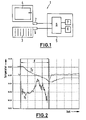
- the device 1 has a sensor 2 which is arranged in the vicinity of a heating surface 3 designed as a heating element and a window 4.
- the sensor 2 is connected to a sensor signal processing device 5.
- the sensor 2 may, for example, be an anemometer with which the flow velocity of the air flowing past is detected.
- the sensor 2 is preferably an electronic temperature sensor, which is heated with a current pulse and cooled by the passing air.
- the time profile of the electrical sensor resistance is then evaluated.
- the sensor 2 may also be an intelligent fluctuation sensor, which consists of a fast-response electronic temperature sensor.
- the amplitude of the temperature in rapid time sequence can be measured one behind the other, so that in the sensor signal processing device 5 in addition to the amplitude and the frequency of deviations from the average temperature profile can be analyzed.
- the analysis is preferably carried out in an arithmetic unit 6 of the sensor signal processing device 5 designed as a computer device. In this case, for example, recourse may be had to known Fourier analysis methods and programs.
- the sensor signal processing device 5 has an integrator 7 and a memory device 8. In successive measured sensor values can be averaged in the integration device 7 in order to also obtain the average temperature profile.
- the sensor 2 may have at its sensor output a low-pass filter, not shown, which smoothes the signal curve.
- the memory device 8 makes it possible to store statistical characteristic data ascertained with the arithmetic unit 6, such as average values and standard deviation of the deviations from the average temperature profile, so that a comparison of the sensor signals over a longer period of time is possible in the sensor signal processing device 5.
- the arithmetic unit 6 can forward a signal to a control and regulating device 9, which is arranged on the thermostatic valve of the radiator 3 and has a motor, not shown, for actuating the thermostatic valve.
- the radiator valve can be closed in discovered window opening to avoid unnecessary heat dissipation.
- the sensor signal processing device 5 and the control and regulating device 9 are shown as separate elements, these may, for example, be integrated into a housing and attached directly to the valve of the radiator 3.
- the sensor 2 it is also conceivable to arrange the sensor 2 in a space which is particularly sensitive to the change in temperature and / or flow velocity in space and to establish the connection to a separate sensor signal processing device via wire or radio.
- the connection between the sensor signal processing device 5 and the control and regulating device 9 may be formed as a wire or radio connection.
- FIG. 2 shows the temperature profile with the window open and closed as a function of time.
- the curve T1 shows a temperature profile measured on the sensor 2 with a short sampling time of a few seconds.
- the temperature profile T1 in contrast to the temperature profile T2 in the interior of the control and control device 9, which is shielded against the turbulence in the vicinity of the radiator 3, significantly higher, high-frequency fluctuations can be seen during the window opening F in the temperature profile T1.
- the temperature profile T1 is essentially constant and undergoes only slight amplitude changes. As tests have shown, variations in the sampling time do not seriously affect the measurement result for the temperature profile T1 as long as the sampling time in relation to the window opening F is short. Therefore, the temperature profile T1 is very suitable for detecting a window opening.
Landscapes
- Engineering & Computer Science (AREA)
- Signal Processing (AREA)
- Physics & Mathematics (AREA)
- Chemical & Material Sciences (AREA)
- Combustion & Propulsion (AREA)
- Mechanical Engineering (AREA)
- General Engineering & Computer Science (AREA)
- Mathematical Physics (AREA)
- Fuzzy Systems (AREA)
- General Physics & Mathematics (AREA)
- Aviation & Aerospace Engineering (AREA)
- Air Conditioning Control Device (AREA)
- Vaporization, Distillation, Condensation, Sublimation, And Cold Traps (AREA)
- Specific Sealing Or Ventilating Devices For Doors And Windows (AREA)
- Indicating Or Recording The Presence, Absence, Or Direction Of Movement (AREA)
- Investigating Or Analysing Materials By Optical Means (AREA)
Abstract
Description
Die Erfindung bezieht sich auf ein Verfahren zur Erkennung einer Fensterlüftung in beheizten Räumen durch Erkennung von Veränderungen in der Temperatur oder Strömungsgeschwindigkeit der Umgebungsluft sowie eine dafür geeignete Vorrichtung.The invention relates to a method for detecting a window ventilation in heated rooms by detecting changes in the temperature or flow velocity of the ambient air and a device suitable for this purpose.
Um wertvolle Heizenergie zu sparen, ist es bei Fensterlüftung angebracht, die Wärmeabgabe der Raumheizflächen zu minimieren. Ein besonders großer Effekt lässt sich dann erzielen, wenn die Raumheizflächen wie üblich in unmittelbarer Nähe der Fenster angeordnet sind. Bei konventionellen Thermostatventilen wird dies durch handbetätigtes Schließen des Thermostatventils erreicht. Bei elektronischen Regeleinrichtungen kann das Schließen der Ventile automatisiert werden, wenn eine entsprechende Fensterlüftungserkennung vorhanden ist.In order to save valuable heating energy, it is appropriate for window ventilation to minimize the heat emission of the space heating surfaces. A particularly great effect can be achieved if the Raumheizflächen are arranged as usual in the immediate vicinity of the windows. In conventional thermostatic valves, this is achieved by manually closing the thermostatic valve. In electronic control devices, the closing of the valves can be automated if a corresponding window ventilation detection is present.
Bekannt sind Systeme (siehe z.B.
Daher ist es Aufgabe der Erfindung, eine sichere und zuverlässige Erkennung einer Fensteröffnung oder dgl. zu ermöglichen.It is therefore an object of the invention to enable a reliable and reliable detection of a window opening or the like.
Diese Aufgabe wird bei einem Verfahren der eingangs genannten Art im Wesentlichen dadurch gelöst, dass die Temperatur und/oder Strömungsgeschwindigkeit über der Zeit gemessen und hieraus ein mittlerer Verlauf der Temperatur und/oder Strömungsgeschwindigkeit ermittelt wird und dass Amplitude und/oder Frequenz der Abweichungen von dem mittleren Verlauf der Temperatur und/oder Strömungsgeschwindigkeit analysiert werden.This object is achieved in a method of the type mentioned essentially in that the temperature and / or flow rate measured over time and from a mean course of the temperature and / or flow rate is determined and that amplitude and / or frequency of the deviations from the average course of temperature and / or flow rate are analyzed.
Der Erfindung liegt die Erkenntnis zugrunde, dass sich bei der Fensteröffnung zwei Luftströmungen überlagern: Die durch Aufsteigen der am Heizkörper erwärmten Luft und Ansaugen der kühleren Bodenluft entstandene sogenannte Raumluftwalze wird durch eine erzwungene konvektive Strömung der einfließenden kälteren Außenluft überlagert. Dadurch entstehen Verwirbelungen und Turbulenzen, die insbesondere im Nahbereich der Heizraumfläche, d.h. des Heizkörpers, ausgeprägt sind. Warme und kalte Luftströmungen verwirbeln dabei so, dass sich örtlich dem mittleren lokalen Temperaturverlauf eine sich zeitlich schneller ändernde Temperaturkomponente überlagert. Durch Messen der Amplitude und/oder der Frequenz der Abweichungen von dem normalen, mittleren Verlauf der Temperatur oder Strömungsgeschwindigkeit kann daher zuverlässig auf eine nachhaltige Veränderung in der Umgebungsvariablen geschlossen werden, die bspw. durch eine Fensteröffnung ausgelöst ist. Insbesondere können die Messungen von Temperatur und Strömungsgeschwindigkeit kombiniert werden. Dann stehen nicht unmittelbar miteinander korrelierte Messwerte zur Verfügung, die aufgrund ihrer Redundanz eine besonders zuverlässige Erkennung einer Fensteröffnung ermöglichen.The invention is based on the finding that two air flows are superimposed on the window opening: the so-called room air roller resulting from rising of the air heated on the radiator and suction of the cooler floor air is superimposed by a forced convective flow of the inflowing colder outside air. This creates turbulences and turbulences, which in particular in the vicinity of the Heizraumfläche, i. of the radiator, are pronounced. Warm and cold air currents swirl in such a way that spatially superimposed on the mean local temperature history a temporally faster changing temperature component. By measuring the amplitude and / or the frequency of the deviations from the normal, mean course of the temperature or flow rate can therefore be reliably concluded that a sustainable change in the environmental variables, which is triggered, for example, by a window opening. In particular, the measurements of temperature and flow velocity can be combined. Then there are not directly correlated measured values available, which allow a particularly reliable detection of a window opening due to their redundancy.
Zur Bestimmung einer Veränderung der Temperatur wird erfindungsgemäß die Amplitude der Temperatur ermittelt, die Abweichung von der mittleren Temperatur bestimmt und die Frequenz der Abweichungen analysiert. Aufgrund der Durchmischung von kalter und warmer Luft fluktuiert während des Lüftungsvorgangs der aufgenommene Temperaturverlauf stärker als bei geschlossenem Fenster. Diese Fluktuationen werden durch Bestimmung von Amplitude und Frequenz zuverlässig ermittelt.To determine a change in temperature, the amplitude of the temperature is determined according to the invention, the deviation from the mean temperature determined and analyzed the frequency of deviations. Due to the mixing of cold and warm air during the ventilation process, the recorded temperature changes more than when the window is closed. These fluctuations are reliably determined by determining amplitude and frequency.
Vorzugsweise wird dazu ein schnell ansprechender Temperatursensor verwendet, der die Amplitude der Temperatur in kurzen zeitlichen Abständen misst.Preferably, a fast-response temperature sensor is used, which measures the amplitude of the temperature at short time intervals.
Zur Bestimmung einer Veränderung der Strömungsgeschwindigkeit wird die Amplitude der Strömungsgeschwindigkeit ermittelt und die Abweichung von der mittleren Strömungsgeschwindigkeit bestimmt. Aus der Größe (Amplitude) der Abweichungen kann dann auf die Fensteröffnung geschlossen werden, da derartige Abweichungen in geschlossenen Räumen nicht auftreten. Typische Geschwindigkeiten der Aufwärtsströmung am Heizkörper betragen etwa 0,4 bis 0,8 m/s, wobei die strömende Grenzschicht relativ dünn ist. Die Geschwindigkeit hängt von der Übertemperatur und der Höhe des Heizkörpers ab. Eine Strömungsgeschwindigkeit von 0,8 m/s wird bspw. bei einem Heizkörper mit etwa 70° C Oberflächentemperatur und 1 m Höhe erreicht. Zusätzlich kann auch die Frequenz der Abweichungen in der Strömungsgeschwindigkeit analysiert werden, um die Turbulenzen in der Strömungsgeschwindigkeit sicher zu erfassen.In order to determine a change in the flow velocity, the amplitude of the flow velocity is determined and the deviation from the average flow velocity is determined. From the size (amplitude) of the deviations can then be closed to the window opening, since such deviations do not occur in enclosed spaces. Typical upward flow rates at the heater are about 0.4 to 0.8 m / s, with the flowing boundary layer being relatively thin. The speed depends on the overtemperature and the height of the radiator. A flow velocity of 0.8 m / s is achieved, for example, in the case of a radiator with a surface temperature of approximately 70 ° C. and a height of 1 m. In addition, the frequency of the deviations in the flow velocity can also be analyzed in order to reliably detect the turbulence in the flow velocity.
Erfindungsgemäß wird zur Messung der Strömungsgeschwindigkeit ein Anemometer, bspw. ein Hitzedraht- oder Hitzekugelanemometer verwendet. Gemäß einer anderen, besonders bevorzugten Ausführungsform wird jedoch ein Temperatursensor mit einem Strompuls aufgeheizt, wobei er sich durch die vorbeiströmende Luft abkühlt und der zeitliche Verlauf des elektrischen Sensorwiderstandes bestimmt wird. Dieser Sensor zeichnet sich im Vergleich zu den vorgenannten Anemometern durch einen niedrigen Stromverbrauch und einen einfachen technischen Aufbau aus. Daher eignet sich dieser Sensor insbesondere für batteriebetriebene Systeme. Aufgrund der geringen Masse und der großen Oberfläche des Sensors spricht dieser auch hinreichend schnell auf die Temperaturänderung durch die vorbeiströmende Luft an.According to the invention, an anemometer, for example a hot-wire or hot-ball anemometer, is used to measure the flow rate. According to another, particularly preferred embodiment, however, a temperature sensor is heated with a current pulse, wherein it cools down by the air flowing past and the time course of the electrical sensor resistance is determined. This sensor is characterized by a low power consumption and a simple technical structure compared to the aforementioned anemometers. Therefore, this sensor is particularly suitable for battery powered systems. Due to the low mass and the large surface of the sensor, this also responds sufficiently quickly to the temperature change due to the passing air.
Eine einfache Möglichkeit zur Analyse der Amplituden- und Frequenzabweichungen bietet eine Fourieranalyse.A simple way to analyze the amplitude and frequency deviations offers a Fourier analysis.
Vorteilhafterweise werden die ermittelten Abweichungen in Form von statistischen Kenndaten, wie Mittelwert, Standardabweichung oder dgl. festgehalten, um sie mit den ermittelten Kenndaten der nachfolgenden Abweichungen vergleichen zu können.Advantageously, the deviations ascertained are recorded in the form of statistical characteristic data, such as mean value, standard deviation or the like, in order to be able to compare them with the determined characteristics of the following deviations.
Zusätzlich kann der Gradient des mittleren Verlaufs der Temperatur und/oder der Strömungsgeschwindigkeit bestimmt werden, um eine zusätzliche Information über Veränderungen dieser Umgebungsvariablen zu erhalten. Insbesondere kann auch eine Kombination von Temperatur- und Strömungsgeschwindigkeitsmessung durchgeführt werden, bei denen jeweils die Abweichungen in Amplitude und/oder Frequenz bestimmt werden, so dass ein besonders zuverlässiger Rückschluss auf die Ursache der Veränderungen in den Umgebungsvariablen möglich ist.In addition, the gradient of the mean temperature and / or flow velocity can be determined to provide additional information about changes in these environmental variables. In particular, a combination of temperature and flow velocity measurement can be carried out, in which the deviations in amplitude and / or frequency are determined in each case, so that a particularly reliable inference to the cause of the changes in the environmental variables is possible.
Ferner bezieht sich die Erfindung auf eine Vorrichtung zur Erkennung einer Fensterlüftung durch Erkennen von Veränderungen in Temperatur oder Strömungsgeschwindigkeit der Umgebungsluft mit mindestens einem Sensor zum Messen der Amplitude der Temperatur und/oder Strömungsgeschwindigkeit mit einer vorgebbaren Frequenz. Dabei wird durch eine Sensorsignal-Verarbeitungseinrichtung die Amplitude und/oder Frequenz der Abweichungen vom mittleren Verlauf der Temperatur und/oder Strömungsgeschwindigkeit analysiert.Furthermore, the invention relates to a device for detecting a window ventilation by detecting changes in temperature or flow rate of the ambient air with at least one sensor for measuring the amplitude of the temperature and / or flow rate with a predetermined frequency. In this case, the amplitude and / or frequency of the deviations from the average course of the temperature and / or flow rate is analyzed by a sensor signal processing device.
Als Sensor kann ein Anemometer, wie ein Hitzedraht- oder Hitzekugelanemometer, ein stromgepulster Temperatursensor mit temperaturabhängigem Widerstand oder ein Fluktuationssensor, insbesondere ein schnell ansprechender Temperatursensor, verwendet werden. Insbesondere die beiden letztgenannten Sensoren haben einen einfachen technischen Aufbau, so dass sie kostengünstig in den Vorrichtungen verwendet werden können. Die Messvorrichtung kann auch eine Kombination mehrerer dieser Sensoren aufweisen.As the sensor, an anemometer such as a hot-wire or hot-bulb anemometer, a current-pulsed temperature-sensing temperature sensor or a fluctuation sensor, particularly a fast-response temperature sensor, may be used. In particular, the two latter sensors have a simple technical structure, so that they can be used inexpensively in the devices. The measuring device may also comprise a combination of several of these sensors.
Der Sensor kann zur Bearbeitung seines Ausgangssignals einen Tiefpassfilter aufweisen.The sensor may have a low-pass filter for processing its output signal.
Vorzugsweise ist die Sensor-Verarbeitungseinrichtung eine programmgesteuerte Computereinrichtung, in der Programme zur Auswertung der Sensorsignale gespeichert sind. Diese können bspw. mit Hilfe eines Fuzzy-Sets mit aufeinanderfolgenden Wenn-Dann-Abfragen realisiert werden.The sensor processing device is preferably a program-controlled computer device in which programs for evaluating the sensor signals are stored. These can be realized, for example, with the aid of a fuzzy set with successive if-then queries.
Die Sensorsignal-Verarbeitungseinrichtung kann erfindungsgemäß auch eine Integrationseinrichtung zur Bestimmung des mittleren Temperaturverlaufs und/oder der mittleren Strömungsgeschwindigkeit aufweisen, die die Temperatur und/oder die Strömungsgeschwindigkeit über einen längeren Zeitraum aufintegriert und bezogen auf die Integrationszeit einen Mittelwert bestimmt.According to the invention, the sensor signal processing device can also have an integration device for determining the average temperature profile and / or the average flow velocity, which integrates the temperature and / or the flow velocity over a longer period of time and determines an average value based on the integration time.
Außerdem weist die Sensorsignal-Verarbeitungseinrichtung vorzugsweise eine Speichereinrichtung zur Speicherung der Messwerte und Kenndaten auf, so dass diese für spätere Vergleiche zur Verfügung stehen.In addition, the sensor signal processing device preferably has a memory device for storing the measured values and characteristic data, so that these are available for later comparisons.
Gemäß einer speziellen Ausführungsform ist bei der Vorrichtung auch eine mit der Sensorsignal-Verarbeitungseinrichtung über Draht oder Funk verbundene Regel- und Steuereinrichtung vorgesehen, insbesondere zum Öffnen und Schließen von motorbetriebenen Heizkörperventilen. Auf diese Weise kann die durch die Vorrichtung erkannte Fensterlüftung sofort in eine Heizungsregelung an einem motorbetriebenen Thermostatventil umgesetzt werden.According to a specific embodiment, the device also has a regulating and control device connected to the sensor signal processing device via wire or radio, in particular for opening and closing motor-operated radiator valves. In this way, the detected by the device window ventilation immediately be implemented in a heating control on a motor-operated thermostatic valve.
Die Erfindung wird nachfolgend anhand von Ausführungsbeispielen und der Zeichnung näher beschrieben.The invention will be described in more detail with reference to embodiments and the drawing.
Es zeigen:
- Fig. 1
- schematisch den Aufbau der erfindungsgemäßen Vorrichtung zum Erkennen von Veränderungen in den Umgebungsvariablen und
- Fig. 2
- den Temperaturverlauf bei geschlossenem und geöffnetem Fenster
- Fig. 1
- schematically the structure of the device according to the invention for detecting changes in the environment variables and
- Fig. 2
- the temperature profile with the window closed and opened
Die Vorrichtung 1 weist einen Sensor 2 auf, der in der Nähe einer als Heizkörper 3 ausgebildeten Heizfläche und eines Fensters 4 angeordnet ist. Der Sensor 2 ist mit einer Sensorsignal-Verarbeitungseinrichtung 5 verbunden.The device 1 has a
Beim Öffnen des Fensters 4 in einem beheizten Raum strömt kalte Außenluft in das Zimmer ein, die mit der durch freie Konvektion entstandenen Raumwalze verwirbelt. Dies geschieht hauptsächlich in der Nähe des Fensters 4 und des Heizkörpers 3, wo auch der Sensor 2 zur Erfassung von Veränderung der Umgebungsvariablen angeordnet ist. Bei dem Sensor 2 kann es sich bspw. um ein Anemometer handeln, mit dem die Strömungsgeschwindigkeit der vorbeiströmenden Luft erfasst wird. In diesem Fall ist der Sensor 2 vorzugsweise ein elektronischer Temperatursensor, der mit einem Strompuls aufgeheizt und durch die vorbeiströmende Luft abgekühlt wird. In der Sensorsignal-Verarbeitungseinrichtung 5 wird dann der zeitliche Verlauf des elektrischen Sensorwiderstandes ausgewertet.When opening the
Alternativ oder zusätzlich kann der Sensor 2 auch ein intelligenter Fluktuationssensor sein, der aus einem schnell ansprechenden elektronischen Temperatursensor besteht. So kann die Amplitude der Temperatur in schneller zeitlicher Abfolge hintereinander gemessen werden, so dass in der Sensorsignal-Verarbeitungseinrichtung 5 neben der Amplitude auch die Frequenz der Abweichungen vom mittleren Temperaturverlauf analysiert werden kann. Die Analyse geschieht vorzugsweise in einem Rechenwerk 6 der als Computereinrichtung ausgebildeten Sensorsignal-Verarbeltungseinrichtung 5. Dabei kann bspw. auf bekannte Fourier-Analyse-Verfahren und -programme zurückgegriffen werden. Zusätzlich weist die Sensorsignal-Verarbeitungseinrichtung 5 eine Integrationseinrichtung 7 und eine Speichereinrichtung 8 auf. In der Integrationseinrichtung 7 können aufeinanderfolgend gemessene Sensorwerte gemittelt werden, um auch den mittleren Temperaturverlauf zu erhalten. Dazu kann der Sensor 2 an seinem Sensorausgang einen nicht dargestellten Tiefpassfilter aufweisen, der den Signalverlauf glättet.Alternatively or additionally, the
Die Speichereinrichtung 8 ermöglicht das Abspeichern von mit dem Rechenwerk 6 ermittelten statistischen Kenndaten, wie Mittelwerte und Standardabweichung der ermittelten Abweichungen vom mittleren Temperaturverlauf, so dass in der Sensorsignal-Verarbeitungseinrichtung 5 ein Vergleich der Sensorsignale über einen längeren Zeitraum möglich ist.The
Wenn von der Sensorsignal-Verarbeitungseinrichtung 5 eine Fensterlüftung erkannt wurde, kann das Rechenwerk 6 ein Signal an eine Regel- und Steuereinrichtung 9 weiterleiten, die an dem Thermostatventil des Heizkörpers 3 angeordnet ist und einen nicht dargestellten Motor zum Betätigen des Thermostatventils aufweist. So kann das Heizkörperventil bei entdeckter Fensteröffnung geschlossen werden, um eine unnötige Wärmeabgabe zu vermeiden. Wenn das Schließen des Fensters durch eine entsprechende Änderung von Temperatur und/oder Strömungsgeschwindigkeit, die mit dem Sensor 2 nachgewiesen wurde, festgestellt wird, kann die Regel- und Steuereinrichtung 9 das Ventil am Heizkörper 3 wieder öffnen.If a window ventilation has been detected by the sensor
Obwohl in der schematischen Darstellung der Sensor 2, die Sensorsignal-Verarbeitungseinrichtung 5 und die Regel- und Steuereinrichtung 9 als getrennte Elemente dargestellt sind, können diese bspw. in ein Gehäuse integriert und direkt am Ventil des Heizkörpers 3 angebracht sein.Although in the schematic representation of the
Es ist ebenso denkbar, den Sensor 2 an einer für die Veränderung von Temperatur und/oder Strömungsgeschwindigkeit besonders sensitiven Stelle im Raum anzuordnen und die Verbindung zu einer separaten Sensorsignal-Verarbeitungseinrichtung über Draht oder Funk herzustellen. Ebenso kann die Verbindung zwischen der Sensorsignal-Verarbeitungseinrichtung 5 und der Regel- und Steuereinrichtung 9 als Draht- oder Funkverbindung ausgebildet sein.It is also conceivable to arrange the
In Fig. 2 ist der Temperaturverlauf bei geöffnetem und geschlossenem Fenster in Abhängigkeit von der Zeit dargestellt. Die Kurve T1 zeigt einen an dem Sensor 2 mit einer kurzen Abtastzeit von einigen Sekunden gemessenen Temperaturverlauf. Im Gegensatz zu dem Temperaturverlauf T2 im Inneren der Regel- und Steuereinrichtung 9, das gegen die Turbulenzen im Nahbereich des Heizkörpers 3 abgeschirmt ist, sind während der Fensteröffnung F im Temperaturverlauf T1 deutlich stärkere, hochfrequente Schwankungen zu erkennen. Nach dem Schließen des Fensters ist der Temperaturverlauf T1 dagegen im Wesentlichen konstant und unterliegt nur geringen Amplitudenänderungen. Wie Versuche gezeigt haben, beeinflussen Variationen in der Abtastzeit das Messergebnis für den Temperaturverlauf T1 nicht gravierend, solange die Abtastzeit im Verhältnis zur Fensteröffnung F kurz ist. Daher eignet sich der Temperaturverlauf T1 sehr gut zur Erkennung einer Fensteröffnung.FIG. 2 shows the temperature profile with the window open and closed as a function of time. The curve T1 shows a temperature profile measured on the
Durch die Analyse der Amplitude und/oder Frequenz der Abweichungen von Temperatur und/oder Strömungsgeschwindigkeit ist es also möglich, eine Fensterlüftung in beheizten Räumen zuverlässig und sicher nachzuweisen, um ggf. elektronische Regeleinrichtungen zum Schließen und Öffnen der Heizkörperventile zu betätigen.By analyzing the amplitude and / or frequency of the deviations from temperature and / or flow rate, it is thus possible reliably and reliably detect a window ventilation in heated rooms, if necessary to actuate electronic control devices for closing and opening the radiator valves.
- 11
- Vorrichtungcontraption
- 22
- Sensorsensor
- 33
- Heizkörperradiator
- 44
- Fensterwindow
- 55
- Sensorsignal-VerarbeitungseinrichtungSensor signal processing means
- 66
- Rechenwerkcalculator
- 77
- Integrationseinrichtungintegration means
- 88th
- Speichereinrichtungmemory device
- 99
- Regel- und SteuereinrichtungControl and regulating device
- T1T1
- Temperaturverlauftemperature curve
- T2T2
- Temperaturverlauftemperature curve
- FF
- Fensteröffnungwindow opening
Claims (16)
- A method for detecting window ventilation in heated rooms by detecting changes in the temperature and the flow velocity, such as the temperature or flow velocity of the ambient air,
characterised in that the temperature and/or flow velocity is measured over time and a mean course of the temperature and/or flow velocity is determined therefrom
and in that the amplitude and/or frequency of the deviations in the individual measured values from the mean course of the temperature and/or flow velocity are analysed. - A method according to Claim 1,
characterised in that a fast-response temperature sensor is used to measure the amplitude of the temperature in brief time intervals. - A method according to Claim 1,
characterised in that an anemometer, preferably a hot wire or hot ball anemometer, is used to measure the flow velocity. - A method according to Claim 1,
characterised in that a temperature sensor is heated with a current pulse, with it being cooled by the air flowing past,
and in that the temporal course of the electrical sensor resistance is determined. - A method according to one of the preceding Claims,
characterised in that a Fourier analysis of the measurement data is performed to analyse the amplitude and frequency of the deviations. - A method according to one of the preceding Claims,
characterised in that the determined deviations are recorded in the form of statistical characteristic data, such average, standard deviation or the like. - A method according to one of the preceding Claims,
characterised in that the gradient of the mean course of the temperature and/or flow velocity is determined. - A device for detecting window ventilation in heated rooms by detecting changes in the temperature and/or flow velocity of the ambient air, having at least one sensor (2) for measuring the amplitude of the temperature and/or flow velocity with a preset frequency and having a sensor signal processing unit (5) for analysing the amplitude and/or frequency of deviations from the mean course of the temperature and/or flow velocity.
- A device according to Claim 8,
characterised in that the sensor is an anemometer, such as a hot wire or hot ball anemometer. - A device according to Claim 8 or 9,
characterised in that the sensor (2) is a current-pulsed temperature sensor with temperature-dependent resistance. - A device according to one of Claims 8 to 10,
characterised in that the senor (2) is a fluctuation sensor, in particular a fast-response temperature sensor. - A device according to one of Claims 8 to 11,
characterised in that a low-pass filter is provided on the sensor (2). - A device according to one of Claims 8 to 12,
characterised in that the sensor signal processing unit (5) is a programme-controlled computer device. - A device according to one of Claims 8 to 13,
characterised in that the sensor signal processing unit (5) is an integration device (7) for determining the mean temperature profile and/or mean flow velocity. - A device according to one of Claims 8 to 14,
characterised in that the sensor signal processing unit (5) comprises a storage device (8) for storing the measured values and characteristic data. - A device according to one of Claims 8 to 15,
characterised by a control unit (9) connected in wire-bound or wireless manner to the sensor signal processing device (5) for opening and closing motor-driven radiator valves.
Applications Claiming Priority (2)
| Application Number | Priority Date | Filing Date | Title |
|---|---|---|---|
| DE10026957A DE10026957A1 (en) | 2000-05-30 | 2000-05-30 | Method and device for detecting changes in environmental variables |
| DE10026957 | 2000-05-30 |
Publications (2)
| Publication Number | Publication Date |
|---|---|
| EP1160552A1 EP1160552A1 (en) | 2001-12-05 |
| EP1160552B1 true EP1160552B1 (en) | 2007-08-22 |
Family
ID=7644212
Family Applications (1)
| Application Number | Title | Priority Date | Filing Date |
|---|---|---|---|
| EP01111506A Expired - Lifetime EP1160552B1 (en) | 2000-05-30 | 2001-05-11 | Method and device for detecting an opened window |
Country Status (7)
| Country | Link |
|---|---|
| EP (1) | EP1160552B1 (en) |
| AT (1) | ATE371176T1 (en) |
| CZ (1) | CZ20011767A3 (en) |
| DE (2) | DE10026957A1 (en) |
| HU (1) | HUP0102232A3 (en) |
| PL (1) | PL347732A1 (en) |
| SK (1) | SK6802001A3 (en) |
Cited By (1)
| Publication number | Priority date | Publication date | Assignee | Title |
|---|---|---|---|---|
| DE202013012913U1 (en) | 2013-02-22 | 2021-11-16 | Ust Umweltsensortechnik Gmbh | Device for controlling energy consumption in a room |
Families Citing this family (16)
| Publication number | Priority date | Publication date | Assignee | Title |
|---|---|---|---|---|
| DE10208231A1 (en) * | 2002-02-26 | 2003-09-04 | Zahnradfabrik Friedrichshafen | Procedure for calibrating a sensor |
| DE102009023282B3 (en) * | 2009-05-29 | 2010-09-09 | Thomas Beyer | Thermostat valve control for heating system, has rod formed with axial borehole with intermediate tappet, which is in connection between end-sided actuation area of thermostat element and front-sided thrust washer for actuation of tappet |
| US9322569B2 (en) * | 2010-05-03 | 2016-04-26 | Harmonic Design, Inc. | Systems and methods for a motorized vent covering in an environment control system |
| FR2962234B1 (en) * | 2010-07-01 | 2012-07-27 | Atlantic Industrie Sas | METHOD FOR DETECTING THE OPENING AND CLOSING OF AN OPENING IN A WORKPIECE AND THERMAL CONTROL DEVICE IMPLEMENTING SAID METHOD |
| GB201513012D0 (en) * | 2015-06-11 | 2015-09-09 | Eaton Industires Austria Gmbh | Method for the detection of an open ventilation opening |
| US20190078800A1 (en) * | 2016-04-20 | 2019-03-14 | Fandis S.P.A. | Improved cooling system |
| CN106123228A (en) * | 2016-06-30 | 2016-11-16 | 珠海格力电器股份有限公司 | Control device of air conditioner, door and window state detection method and device and air conditioner |
| CN110234933B (en) * | 2016-11-22 | 2021-10-26 | 贝利莫控股公司 | Liquid circulation system and method for operating the same |
| DE102017105388A1 (en) * | 2017-03-14 | 2018-09-20 | Abb Schweiz Ag | Sensor system for detecting arising air or heat flows, caused by open windows, doors and / or other closable openings in a building room |
| CN109282503B (en) * | 2018-09-28 | 2020-11-03 | 中山基尔电器有限公司 | An electric fireplace that can detect open windows |
| CN111006793A (en) * | 2019-12-18 | 2020-04-14 | 北京航空航天大学 | A method for measuring response time of K-type armored thermocouple based on heat pipe method |
| EP4170248B1 (en) * | 2021-10-25 | 2023-12-27 | Siemens Schweiz AG | Detection of windows left opened |
| CN115930317A (en) * | 2022-09-07 | 2023-04-07 | 科宇智能环境技术服务有限公司 | A comprehensive optimization system for geothermal air-conditioning based on multi-energy complementarity |
| DE102022214170A1 (en) | 2022-12-21 | 2024-06-27 | Robert Bosch Gesellschaft mit beschränkter Haftung | Methods for improving indoor air |
| CN115950041B (en) * | 2022-12-26 | 2025-04-15 | 上海建工四建集团有限公司 | A method for identifying and locating doors and windows that are not closed when turning on air conditioning |
| DE102023002879A1 (en) * | 2023-07-15 | 2025-01-16 | Günter Mügge | Method and device for detecting the heat emission of low-temperature radiators |
Family Cites Families (7)
| Publication number | Priority date | Publication date | Assignee | Title |
|---|---|---|---|---|
| SE7407284L (en) * | 1974-08-01 | 1976-02-02 | Welins Einar Patenter Kommandi | WAY TO CHARGE THE FUEL COSTS IN AN APARTMENT HOUSE E.D. ON THE VARIOUS APARTMENTS AND APPROPRIATE DEVICES ATTACHMENTS FOR SATURATION AND FOR CALCULATION AND PRESENTATION OF THE WORLDS REQUIRED FOR THE DISTRIBUTION |
| US4773183A (en) * | 1986-02-28 | 1988-09-27 | Omron Tateisi Electronics Co. | Contact sensitive control apparatus |
| DE4015072A1 (en) * | 1990-04-27 | 1991-10-31 | Erhard Raddatz | Registering just proportion of cost in central heated building - using continuously working temp. measuring appts. in each room taking into consideration size of room, initial temp. and ambient temp. |
| DE4213221C2 (en) * | 1992-04-22 | 2001-05-17 | Porsche Ag | Method for determining the wetting of a road surface |
| DE4424811C2 (en) * | 1994-07-14 | 2003-05-28 | Bosch Gmbh Robert | Method for forming a simulated signal relating to a temperature in the exhaust system of an internal combustion engine |
| DE4440389C2 (en) * | 1994-11-11 | 1996-08-14 | Werner Julius Pof Dr | Combination sensor for the detection of atmospheric variables, in particular for the diagnosis of icing and wind loads on technical objects |
| CA2293475C (en) * | 1997-06-15 | 2007-12-04 | Elwe Technik Gmbh | Meteorological electromagnetic measuring system |
-
2000
- 2000-05-30 DE DE10026957A patent/DE10026957A1/en not_active Ceased
-
2001
- 2001-05-11 AT AT01111506T patent/ATE371176T1/en active
- 2001-05-11 EP EP01111506A patent/EP1160552B1/en not_active Expired - Lifetime
- 2001-05-11 DE DE50112898T patent/DE50112898D1/en not_active Expired - Lifetime
- 2001-05-18 SK SK680-2001A patent/SK6802001A3/en unknown
- 2001-05-21 CZ CZ20011767A patent/CZ20011767A3/en unknown
- 2001-05-25 PL PL01347732A patent/PL347732A1/en not_active IP Right Cessation
- 2001-05-29 HU HU0102232A patent/HUP0102232A3/en unknown
Cited By (1)
| Publication number | Priority date | Publication date | Assignee | Title |
|---|---|---|---|---|
| DE202013012913U1 (en) | 2013-02-22 | 2021-11-16 | Ust Umweltsensortechnik Gmbh | Device for controlling energy consumption in a room |
Also Published As
| Publication number | Publication date |
|---|---|
| CZ20011767A3 (en) | 2002-01-16 |
| SK6802001A3 (en) | 2001-12-03 |
| DE50112898D1 (en) | 2007-10-04 |
| PL347732A1 (en) | 2001-12-03 |
| HUP0102232A3 (en) | 2002-12-28 |
| HUP0102232A2 (en) | 2002-02-28 |
| ATE371176T1 (en) | 2007-09-15 |
| EP1160552A1 (en) | 2001-12-05 |
| HU0102232D0 (en) | 2001-08-28 |
| DE10026957A1 (en) | 2001-12-13 |
Similar Documents
| Publication | Publication Date | Title |
|---|---|---|
| EP1160552B1 (en) | Method and device for detecting an opened window | |
| DE69823400T2 (en) | Monitoring the air cooling of integrated circuits in electronic devices | |
| DE102016211840B3 (en) | Mold Detector | |
| DE10038233A1 (en) | State machine controller for building heating, cooling and air-conditioning system determines e.g. if controller is saturated by evaluating operating data | |
| DE102008044439A1 (en) | Regulation device for automatic ventilation of cellar areas in building for construction industry, has controller connected to ventilator, window drive and/or control valve for controlling operation of ventilator | |
| DE10302285A1 (en) | Method for determining the interior temperature of a motor vehicle passenger compartment, arrangement for carrying out the method and temperature sensor | |
| DE102006058617B3 (en) | Steam quantity temporal distribution determining method for use in oven, involves measuring temporal distribution of temperature at head to cooking chamber atmosphere and determining distribution of quantity based on measurement signals | |
| WO2016166158A1 (en) | Device for window-handle or door-handle position detection on the basis of magnetic field sensing, and operating method therefor | |
| DE69919047T2 (en) | Double system for temperature control for incubator | |
| Zhang et al. | Estimating the number of occupants and activity intensity in large spaces with environmental sensors | |
| DE19634338A1 (en) | Warning system for alerting damp damage e.g. mould at inner sides of enclosed room | |
| DE102012201703A1 (en) | Automatic fire detector for the detection of fires | |
| DE102007057520A1 (en) | Measurement of the ambient temperature with a gas sensor element | |
| DE19964193A1 (en) | Procedure to determine ambient pressure of combustion engine | |
| EP3376189B1 (en) | Sensor system for detecting air or heat flows due to open window, doors and/or other closable openings in a building room | |
| EP2469174A2 (en) | Cooking device | |
| DE202019001963U1 (en) | Point detector, in particular fire or smoke detector, with at least one thermally decoupled on an associated circuit substrate arranged temperature sensor | |
| DE102015201155B4 (en) | Apparatus and method for temperature detection | |
| EP1235130B1 (en) | Method and device for controlling the room temperature | |
| EP1139099B1 (en) | Operation method for an alcohol sensor | |
| DE102011088919B3 (en) | Method for checking functionality of two controllable valves of cooling system for engine of vehicle, involves detecting valve which is in closed state to be defective when other valve is in opened state | |
| DE102007059253A1 (en) | Method and device for detecting the heat emission of a heating surface | |
| CN118111190A (en) | Visual management system of freezer | |
| DE102015101407B4 (en) | Energy meter and method for detecting an amount of energy supplied by a heating and / or air conditioning center to a consumer | |
| EP0796751B1 (en) | Air conditioning device |
Legal Events
| Date | Code | Title | Description |
|---|---|---|---|
| PUAI | Public reference made under article 153(3) epc to a published international application that has entered the european phase |
Free format text: ORIGINAL CODE: 0009012 |
|
| AK | Designated contracting states |
Kind code of ref document: A1 Designated state(s): AT BE CH CY DE DK ES FI FR GB GR IE IT LI LU MC NL PT SE TR |
|
| AX | Request for extension of the european patent |
Free format text: AL;LT;LV;MK;RO;SI |
|
| 17P | Request for examination filed |
Effective date: 20011122 |
|
| AKX | Designation fees paid |
Free format text: AT BE CH CY DE DK ES FI FR GB GR IE IT LI LU MC NL PT SE TR |
|
| RAP1 | Party data changed (applicant data changed or rights of an application transferred) |
Owner name: TECHEM ENERGY SERVICES GMBH |
|
| 17Q | First examination report despatched |
Effective date: 20060629 |
|
| GRAP | Despatch of communication of intention to grant a patent |
Free format text: ORIGINAL CODE: EPIDOSNIGR1 |
|
| GRAS | Grant fee paid |
Free format text: ORIGINAL CODE: EPIDOSNIGR3 |
|
| GRAA | (expected) grant |
Free format text: ORIGINAL CODE: 0009210 |
|
| AK | Designated contracting states |
Kind code of ref document: B1 Designated state(s): AT BE CH CY DE DK ES FI FR GB GR IE IT LI LU MC NL PT SE TR |
|
| REG | Reference to a national code |
Ref country code: GB Ref legal event code: FG4D Free format text: NOT ENGLISH |
|
| REG | Reference to a national code |
Ref country code: CH Ref legal event code: EP |
|
| REG | Reference to a national code |
Ref country code: IE Ref legal event code: FG4D Free format text: LANGUAGE OF EP DOCUMENT: GERMAN |
|
| REF | Corresponds to: |
Ref document number: 50112898 Country of ref document: DE Date of ref document: 20071004 Kind code of ref document: P |
|
| REG | Reference to a national code |
Ref country code: CH Ref legal event code: NV Representative=s name: A. BRAUN, BRAUN, HERITIER, ESCHMANN AG PATENTANWAE |
|
| PG25 | Lapsed in a contracting state [announced via postgrant information from national office to epo] |
Ref country code: FI Free format text: LAPSE BECAUSE OF FAILURE TO SUBMIT A TRANSLATION OF THE DESCRIPTION OR TO PAY THE FEE WITHIN THE PRESCRIBED TIME-LIMIT Effective date: 20070822 Ref country code: NL Free format text: LAPSE BECAUSE OF FAILURE TO SUBMIT A TRANSLATION OF THE DESCRIPTION OR TO PAY THE FEE WITHIN THE PRESCRIBED TIME-LIMIT Effective date: 20070822 Ref country code: ES Free format text: LAPSE BECAUSE OF FAILURE TO SUBMIT A TRANSLATION OF THE DESCRIPTION OR TO PAY THE FEE WITHIN THE PRESCRIBED TIME-LIMIT Effective date: 20071203 |
|
| NLV1 | Nl: lapsed or annulled due to failure to fulfill the requirements of art. 29p and 29m of the patents act | ||
| GBV | Gb: ep patent (uk) treated as always having been void in accordance with gb section 77(7)/1977 [no translation filed] |
Effective date: 20070822 |
|
| REG | Reference to a national code |
Ref country code: IE Ref legal event code: FD4D |
|
| EN | Fr: translation not filed | ||
| PG25 | Lapsed in a contracting state [announced via postgrant information from national office to epo] |
Ref country code: GR Free format text: LAPSE BECAUSE OF FAILURE TO SUBMIT A TRANSLATION OF THE DESCRIPTION OR TO PAY THE FEE WITHIN THE PRESCRIBED TIME-LIMIT Effective date: 20071123 Ref country code: DK Free format text: LAPSE BECAUSE OF FAILURE TO SUBMIT A TRANSLATION OF THE DESCRIPTION OR TO PAY THE FEE WITHIN THE PRESCRIBED TIME-LIMIT Effective date: 20070822 |
|
| PG25 | Lapsed in a contracting state [announced via postgrant information from national office to epo] |
Ref country code: GB Free format text: LAPSE BECAUSE OF FAILURE TO SUBMIT A TRANSLATION OF THE DESCRIPTION OR TO PAY THE FEE WITHIN THE PRESCRIBED TIME-LIMIT Effective date: 20070822 Ref country code: PT Free format text: LAPSE BECAUSE OF FAILURE TO SUBMIT A TRANSLATION OF THE DESCRIPTION OR TO PAY THE FEE WITHIN THE PRESCRIBED TIME-LIMIT Effective date: 20080122 Ref country code: IE Free format text: LAPSE BECAUSE OF FAILURE TO SUBMIT A TRANSLATION OF THE DESCRIPTION OR TO PAY THE FEE WITHIN THE PRESCRIBED TIME-LIMIT Effective date: 20070822 |
|
| REG | Reference to a national code |
Ref country code: CH Ref legal event code: PFA Owner name: TECHEM ENERGY SERVICES GMBH Free format text: TECHEM ENERGY SERVICES GMBH#HAUPTSTRASSE 89#65760 ESCHBORN (DE) -TRANSFER TO- TECHEM ENERGY SERVICES GMBH#HAUPTSTRASSE 89#65760 ESCHBORN (DE) |
|
| PLBE | No opposition filed within time limit |
Free format text: ORIGINAL CODE: 0009261 |
|
| STAA | Information on the status of an ep patent application or granted ep patent |
Free format text: STATUS: NO OPPOSITION FILED WITHIN TIME LIMIT |
|
| PG25 | Lapsed in a contracting state [announced via postgrant information from national office to epo] |
Ref country code: SE Free format text: LAPSE BECAUSE OF FAILURE TO SUBMIT A TRANSLATION OF THE DESCRIPTION OR TO PAY THE FEE WITHIN THE PRESCRIBED TIME-LIMIT Effective date: 20071122 |
|
| 26N | No opposition filed |
Effective date: 20080526 |
|
| BERE | Be: lapsed |
Owner name: TECHEM ENERGY SERVICES G.M.B.H. Effective date: 20080531 |
|
| PG25 | Lapsed in a contracting state [announced via postgrant information from national office to epo] |
Ref country code: MC Free format text: LAPSE BECAUSE OF NON-PAYMENT OF DUE FEES Effective date: 20080531 |
|
| PG25 | Lapsed in a contracting state [announced via postgrant information from national office to epo] |
Ref country code: BE Free format text: LAPSE BECAUSE OF NON-PAYMENT OF DUE FEES Effective date: 20080531 |
|
| PG25 | Lapsed in a contracting state [announced via postgrant information from national office to epo] |
Ref country code: CY Free format text: LAPSE BECAUSE OF FAILURE TO SUBMIT A TRANSLATION OF THE DESCRIPTION OR TO PAY THE FEE WITHIN THE PRESCRIBED TIME-LIMIT Effective date: 20070822 |
|
| PG25 | Lapsed in a contracting state [announced via postgrant information from national office to epo] |
Ref country code: LU Free format text: LAPSE BECAUSE OF NON-PAYMENT OF DUE FEES Effective date: 20080511 |
|
| PG25 | Lapsed in a contracting state [announced via postgrant information from national office to epo] |
Ref country code: TR Free format text: LAPSE BECAUSE OF FAILURE TO SUBMIT A TRANSLATION OF THE DESCRIPTION OR TO PAY THE FEE WITHIN THE PRESCRIBED TIME-LIMIT Effective date: 20070822 |
|
| PG25 | Lapsed in a contracting state [announced via postgrant information from national office to epo] |
Ref country code: IT Free format text: LAPSE BECAUSE OF NON-PAYMENT OF DUE FEES Effective date: 20080531 |
|
| PG25 | Lapsed in a contracting state [announced via postgrant information from national office to epo] |
Ref country code: FR Free format text: LAPSE BECAUSE OF FAILURE TO SUBMIT A TRANSLATION OF THE DESCRIPTION OR TO PAY THE FEE WITHIN THE PRESCRIBED TIME-LIMIT Effective date: 20080418 |
|
| PGFP | Annual fee paid to national office [announced via postgrant information from national office to epo] |
Ref country code: AT Payment date: 20120521 Year of fee payment: 12 |
|
| PGFP | Annual fee paid to national office [announced via postgrant information from national office to epo] |
Ref country code: CH Payment date: 20130522 Year of fee payment: 13 |
|
| PGFP | Annual fee paid to national office [announced via postgrant information from national office to epo] |
Ref country code: DE Payment date: 20130724 Year of fee payment: 13 |
|
| REG | Reference to a national code |
Ref country code: CH Ref legal event code: PCAR Free format text: NEW ADDRESS: HOLBEINSTRASSE 36-38, 4051 BASEL (CH) |
|
| REG | Reference to a national code |
Ref country code: DE Ref legal event code: R119 Ref document number: 50112898 Country of ref document: DE |
|
| REG | Reference to a national code |
Ref country code: CH Ref legal event code: PL |
|
| REG | Reference to a national code |
Ref country code: AT Ref legal event code: MM01 Ref document number: 371176 Country of ref document: AT Kind code of ref document: T Effective date: 20140511 |
|
| PG25 | Lapsed in a contracting state [announced via postgrant information from national office to epo] |
Ref country code: LI Free format text: LAPSE BECAUSE OF NON-PAYMENT OF DUE FEES Effective date: 20140531 Ref country code: CH Free format text: LAPSE BECAUSE OF NON-PAYMENT OF DUE FEES Effective date: 20140531 |
|
| REG | Reference to a national code |
Ref country code: DE Ref legal event code: R119 Ref document number: 50112898 Country of ref document: DE Effective date: 20141202 |
|
| PG25 | Lapsed in a contracting state [announced via postgrant information from national office to epo] |
Ref country code: AT Free format text: LAPSE BECAUSE OF NON-PAYMENT OF DUE FEES Effective date: 20140511 |
|
| PG25 | Lapsed in a contracting state [announced via postgrant information from national office to epo] |
Ref country code: DE Free format text: LAPSE BECAUSE OF NON-PAYMENT OF DUE FEES Effective date: 20141202 |