EP3708929B1 - Refrigeration cycle device - Google Patents
Refrigeration cycle device Download PDFInfo
- Publication number
- EP3708929B1 EP3708929B1 EP18875034.3A EP18875034A EP3708929B1 EP 3708929 B1 EP3708929 B1 EP 3708929B1 EP 18875034 A EP18875034 A EP 18875034A EP 3708929 B1 EP3708929 B1 EP 3708929B1
- Authority
- EP
- European Patent Office
- Prior art keywords
- refrigerant
- temperature
- heat exchange
- exchange unit
- defrost
- Prior art date
- Legal status (The legal status is an assumption and is not a legal conclusion. Google has not performed a legal analysis and makes no representation as to the accuracy of the status listed.)
- Active
Links
- 238000005057 refrigeration Methods 0.000 title description 4
- 239000003507 refrigerant Substances 0.000 claims description 582
- 230000007246 mechanism Effects 0.000 claims description 122
- 238000009529 body temperature measurement Methods 0.000 claims description 18
- 239000007788 liquid Substances 0.000 description 51
- 238000010438 heat treatment Methods 0.000 description 43
- 238000002347 injection Methods 0.000 description 27
- 239000007924 injection Substances 0.000 description 27
- 230000006835 compression Effects 0.000 description 18
- 238000007906 compression Methods 0.000 description 18
- 230000006870 function Effects 0.000 description 18
- 238000011144 upstream manufacturing Methods 0.000 description 18
- 238000001816 cooling Methods 0.000 description 15
- 238000010257 thawing Methods 0.000 description 15
- 238000005259 measurement Methods 0.000 description 10
- 230000004048 modification Effects 0.000 description 10
- 238000012986 modification Methods 0.000 description 10
- 238000012546 transfer Methods 0.000 description 9
- 238000004378 air conditioning Methods 0.000 description 4
- 238000004891 communication Methods 0.000 description 3
- 238000010586 diagram Methods 0.000 description 3
- 239000006096 absorbing agent Substances 0.000 description 2
- 230000015572 biosynthetic process Effects 0.000 description 2
- 230000008859 change Effects 0.000 description 2
- 238000002360 preparation method Methods 0.000 description 2
- 230000002035 prolonged effect Effects 0.000 description 2
- XLYOFNOQVPJJNP-UHFFFAOYSA-N water Substances O XLYOFNOQVPJJNP-UHFFFAOYSA-N 0.000 description 2
- 238000009825 accumulation Methods 0.000 description 1
- 238000002485 combustion reaction Methods 0.000 description 1
- 238000009833 condensation Methods 0.000 description 1
- 230000005494 condensation Effects 0.000 description 1
- 238000006073 displacement reaction Methods 0.000 description 1
- 238000001704 evaporation Methods 0.000 description 1
- 230000008020 evaporation Effects 0.000 description 1
- NBVXSUQYWXRMNV-UHFFFAOYSA-N fluoromethane Chemical compound FC NBVXSUQYWXRMNV-UHFFFAOYSA-N 0.000 description 1
- 230000005764 inhibitory process Effects 0.000 description 1
- 238000000034 method Methods 0.000 description 1
- 230000009467 reduction Effects 0.000 description 1
- 238000000926 separation method Methods 0.000 description 1
- 239000000243 solution Substances 0.000 description 1
- 238000004781 supercooling Methods 0.000 description 1
Images


Classifications
-
- F—MECHANICAL ENGINEERING; LIGHTING; HEATING; WEAPONS; BLASTING
- F25—REFRIGERATION OR COOLING; COMBINED HEATING AND REFRIGERATION SYSTEMS; HEAT PUMP SYSTEMS; MANUFACTURE OR STORAGE OF ICE; LIQUEFACTION SOLIDIFICATION OF GASES
- F25B—REFRIGERATION MACHINES, PLANTS OR SYSTEMS; COMBINED HEATING AND REFRIGERATION SYSTEMS; HEAT PUMP SYSTEMS
- F25B13/00—Compression machines, plants or systems, with reversible cycle
-
- F—MECHANICAL ENGINEERING; LIGHTING; HEATING; WEAPONS; BLASTING
- F25—REFRIGERATION OR COOLING; COMBINED HEATING AND REFRIGERATION SYSTEMS; HEAT PUMP SYSTEMS; MANUFACTURE OR STORAGE OF ICE; LIQUEFACTION SOLIDIFICATION OF GASES
- F25B—REFRIGERATION MACHINES, PLANTS OR SYSTEMS; COMBINED HEATING AND REFRIGERATION SYSTEMS; HEAT PUMP SYSTEMS
- F25B47/00—Arrangements for preventing or removing deposits or corrosion, not provided for in another subclass
- F25B47/02—Defrosting cycles
- F25B47/022—Defrosting cycles hot gas defrosting
- F25B47/025—Defrosting cycles hot gas defrosting by reversing the cycle
-
- F—MECHANICAL ENGINEERING; LIGHTING; HEATING; WEAPONS; BLASTING
- F25—REFRIGERATION OR COOLING; COMBINED HEATING AND REFRIGERATION SYSTEMS; HEAT PUMP SYSTEMS; MANUFACTURE OR STORAGE OF ICE; LIQUEFACTION SOLIDIFICATION OF GASES
- F25B—REFRIGERATION MACHINES, PLANTS OR SYSTEMS; COMBINED HEATING AND REFRIGERATION SYSTEMS; HEAT PUMP SYSTEMS
- F25B49/00—Arrangement or mounting of control or safety devices
- F25B49/02—Arrangement or mounting of control or safety devices for compression type machines, plants or systems
-
- F—MECHANICAL ENGINEERING; LIGHTING; HEATING; WEAPONS; BLASTING
- F25—REFRIGERATION OR COOLING; COMBINED HEATING AND REFRIGERATION SYSTEMS; HEAT PUMP SYSTEMS; MANUFACTURE OR STORAGE OF ICE; LIQUEFACTION SOLIDIFICATION OF GASES
- F25B—REFRIGERATION MACHINES, PLANTS OR SYSTEMS; COMBINED HEATING AND REFRIGERATION SYSTEMS; HEAT PUMP SYSTEMS
- F25B6/00—Compression machines, plants or systems, with several condenser circuits
- F25B6/04—Compression machines, plants or systems, with several condenser circuits arranged in series
-
- F—MECHANICAL ENGINEERING; LIGHTING; HEATING; WEAPONS; BLASTING
- F25—REFRIGERATION OR COOLING; COMBINED HEATING AND REFRIGERATION SYSTEMS; HEAT PUMP SYSTEMS; MANUFACTURE OR STORAGE OF ICE; LIQUEFACTION SOLIDIFICATION OF GASES
- F25B—REFRIGERATION MACHINES, PLANTS OR SYSTEMS; COMBINED HEATING AND REFRIGERATION SYSTEMS; HEAT PUMP SYSTEMS
- F25B2347/00—Details for preventing or removing deposits or corrosion
- F25B2347/02—Details of defrosting cycles
-
- F—MECHANICAL ENGINEERING; LIGHTING; HEATING; WEAPONS; BLASTING
- F25—REFRIGERATION OR COOLING; COMBINED HEATING AND REFRIGERATION SYSTEMS; HEAT PUMP SYSTEMS; MANUFACTURE OR STORAGE OF ICE; LIQUEFACTION SOLIDIFICATION OF GASES
- F25B—REFRIGERATION MACHINES, PLANTS OR SYSTEMS; COMBINED HEATING AND REFRIGERATION SYSTEMS; HEAT PUMP SYSTEMS
- F25B2700/00—Sensing or detecting of parameters; Sensors therefor
- F25B2700/21—Temperatures
- F25B2700/2103—Temperatures near a heat exchanger
Definitions
- the present disclosure relates to a refrigerant cycle apparatus, and particularly to a refrigerant cycle apparatus configured to execute defrost operation of causing a refrigerant to flow in a direction opposite to a direction during normal operation, for removal of frost adhering to a heat exchange unit during the normal operation.
- a refrigerant cycle apparatus configured to execute defrost operation of causing a refrigerant to flow in a heat exchange unit, so as to cause the heat exchange unit to serve as a refrigerant cooler (radiator), in a direction opposite to a direction during normal operation, for removal of frost adhering to the heat exchange unit which serves as a refrigerant heater (heat absorber) during the normal operation.
- JP S63-201442 A discloses a refrigerant cycle apparatus configured to measure temperature of a refrigerant downstream of a heat exchange unit as a defrosting target during defrost operation (herein, the temperature of the refrigerant downstream of the heat exchange unit in a refrigerant flow direction during the defrost operation will be simply called downstream refrigerant temperature for simple description), and determine completion of defrosting based on the downstream refrigerant temperature.
- JP 2007 232274 A discloses an air conditioner according to the preamble of claim 1 wherein discharged gas is sent into an inlet side pipe arrangement of a heat exchanger supercooling pipe arranged in a lowermost row of an outdoor heat exchanger so that accumulation of the water from ice melted by defrosting as well as icing in the next heating operation is prevented.
- Such a heat exchange unit may include a main heat exchange unit, a sub heat exchange unit, and a pressure loss portion disposed on a refrigerant flow path between the main heat exchange unit and the sub heat exchange unit, and may be configured to cause a refrigerant to flow in an order of the sub heat exchange unit, the pressure loss portion, and the main heat exchange unit during normal operation and cause the refrigerant to flow in a direction opposite to the direction of the normal operation during defrost operation.
- the sub heat exchange unit is disposed upstream of the pressure loss portion causing a pressure drop of the refrigerant in a refrigerant flow direction during the normal operation.
- the refrigerant flowing in the sub heat exchange unit is thus higher in temperature than the refrigerant flowing in the main heat exchange unit during the normal operation.
- the sub heat exchange unit is less likely to have problematic frost. For example, even when the main heat exchange unit is desired to be defrosted, the sub heat exchange unit may not particularly need defrosting in some cases.
- the downstream refrigerant temperature increases based on temperature increase of the entire heat exchange unit. Therefore, even when the sub heat exchange unit does not need defrosting, the defrost operation may not be terminated until the temperature of the entire heat exchange unit including the sub heat exchange unit rises and the defrost operation may be unnecessarily prolonged.
- a refrigerant cycle apparatus includes a refrigerant circuit, a first refrigerant temperature measurement unit, a second refrigerant temperature measurement unit, and an operation control unit.
- the refrigerant circuit includes a compressor, a first heat exchange unit, a second heat exchange unit, an expansion mechanism, and a flow direction switching mechanism.
- the compressor compresses a refrigerant.
- the first heat exchange unit includes a main heat exchange unit, a sub heat exchange unit, and a pressure loss portion disposed on a refrigerant flow path between the main heat exchange unit and the sub heat exchange unit.
- the expansion mechanism is disposed on the refrigerant flow path between the first heat exchange unit and the second heat exchange unit, and decompresses the refrigerant.
- the flow direction switching mechanism switches a flow direction of the refrigerant discharged from the compressor, between a first flow direction and a second flow direction.
- the refrigerant flowing in the first flow direction flows to the second heat exchange unit, the expansion mechanism, the sub heat exchange unit, the pressure loss portion, and the main heat exchange unit in the mentioned order.
- the refrigerant flowing in the second flow direction flows in a direction opposite to the first flow direction. Specifically, the refrigerant flowing in the second flow direction flows to the main heat exchange unit, the pressure loss portion, the sub heat exchange unit, the expansion mechanism, and the second heat exchange unit in the mentioned order.
- the first refrigerant temperature measurement unit measures temperature, as first refrigerant temperature, of the refrigerant flowing in the main heat exchange unit or between the main heat exchange unit and the pressure loss portion.
- the second refrigerant temperature measurement unit measures temperature, as second refrigerant temperature, of the refrigerant flowing between the pressure loss portion and the expansion mechanism.
- the operation control unit controls the flow direction switching mechanism to switch between normal operation of causing the refrigerant to flow in the first flow direction and defrost operation of causing the refrigerant to flow in the second flow direction.
- the operation control unit has control modes for the defrost operation, including at least a first defrost control mode and a second defrost control mode.
- the operation control unit terminates the defrost operation based on the first refrigerant temperature.
- the operation control unit terminates the defrost operation based on the second refrigerant temperature.
- the present refrigerant cycle apparatus operating in the first defrost control mode is configured to terminate the defrost operation based on a defrosting status at the main heat exchange unit, to suppress extension of defrost time when the sub heat exchange unit does not particularly need defrosting.
- the operation control unit in the refrigerant cycle apparatus executes the defrost operation in the first defrost control mode when the second refrigerant temperature measured before the defrost operation starts is equal to or more than first temperature.
- the defrost operation in the first defrost control mode is executed when the second refrigerant temperature before the defrost operation starts is relatively high. This configuration suppresses unnecessary extension of the defrost time when the sub heat exchange unit does not particularly need defrosting.
- the operation control unit in the refrigerant cycle apparatus executes the defrost operation in the first defrost control mode when the second refrigerant temperature measured during the normal operation before the defrost operation starts is equal to or more than the first temperature.
- the defrost operation is executed in the first defrost control mode when the sub heat exchange unit is less likely to have frost or frost on the sub heat exchange unit is likely to melt during the normal operation.
- This configuration suppresses unnecessary extension of the defrost time when the sub heat exchange unit does not particularly need defrosting.
- the operation control unit in the refrigerant cycle apparatus executes the defrost operation in the second defrost control mode when the measured second refrigerant temperature is less than the first temperature.
- This configuration is likely to suppress frost from remaining unmelted at the heat exchange unit including the sub heat exchange unit.
- the refrigerant cycle apparatus further includes an air temperature measurement unit.
- the air temperature measurement unit measures air temperature around the first heat exchange unit.
- the operation control unit executes the defrost operation in the first defrost control mode when the air temperature is equal to or more than second temperature.
- the defrost operation is executed in the first defrost control mode when the air temperature around the first heat exchange unit is relatively high and the sub heat exchange unit is less likely to have frost or frost on the sub heat exchange unit is likely to melt. This configuration is therefore likely to suppress unnecessary extension of the defrost time.
- the operation control unit in the refrigerant cycle apparatus executes the defrost operation in the second defrost control mode when the air temperature is less than the second temperature.
- This configuration is likely to suppress frost from remaining unmelted at the heat exchange unit including the sub heat exchange unit even when the air temperature around the first heat exchange unit is relatively low.
- the pressure loss portion in the refrigerant cycle apparatus is a branching portion of the refrigerant flow path in the first flow direction.
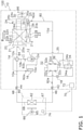
- FIG. 1 is a schematic configuration diagram of a refrigerant cycle apparatus 100 according to a practical example.
- the refrigerant cycle apparatus 100 herein is an air conditioner configured to cool or heat an interior of a building by means of a vapor compression refrigeration cycle.
- the refrigerant cycle apparatus 100 should not be limited to the air conditioner, but may alternatively be configured as a different apparatus such as a hot water supply apparatus.
- the refrigerant cycle apparatus 100 principally includes a heat source unit 10, a utilization unit 60, a liquid-refrigerant connection pipe 46, and a gas-refrigerant connection pipe 48 (see FIG. 1 ).
- the liquid-refrigerant connection pipe 46 and the gas-refrigerant connection pipe 48 connect the heat source unit 10 and the utilization unit 60.
- the liquid-refrigerant connection pipe 46 and the gas-refrigerant connection pipe 48 are constructed onsite when the refrigerant cycle apparatus 100 is installed.
- the refrigerant cycle apparatus 100 includes the single utilization unit 60, but may alternatively include a plurality of utilization units 60 connected in parallel.
- the heat source unit 10 and the utilization unit 60 are connected via the liquid-refrigerant connection pipe 46 and the gas-refrigerant connection pipe 48 to constitute a refrigerant circuit 80.
- the refrigerant circuit 80 principally includes a compressor 12, a heat source heat exchanger 20, an expansion mechanism 18, and a flow direction switching mechanism 14 included in the heat source unit 10, and a utilization heat exchanger 62 included in the utilization unit 60.
- a refrigerant adopted in the refrigerant cycle apparatus 100 may be a fluorocarbon refrigerant such as R32.
- the refrigerant adopted in the refrigerant cycle apparatus 100 may alternatively be a natural refrigerant.
- the refrigerant cycle apparatus 100 is configured to execute cooling operation, heating operation, and defrost operation.
- the cooling operation is executed to cool air in an air conditioning target space provided with the utilization unit 60.
- the heating operation is executed to heat air in the air conditioning target space provided with the utilization unit 60.
- the defrost operation is executed to achieve a principal object of removing frost formed on the heat source heat exchanger 20.
- the utilization unit 60 is installed in the air conditioning target space such as an interior of a building.
- the utilization unit 60 may be of a ceiling embedded type to be installed in a ceiling.
- the utilization unit 60 should not be limited to the ceiling embedded type, but may alternatively be of a ceiling pendant type, a wall mounted type to be mounted on a wall, a floor mount type to be placed on a floor, or the like.
- the utilization unit 60 is connected to the heat source unit 10 via the liquid-refrigerant connection pipe 46 and the gas-refrigerant connection pipe 48, and constitutes part of the refrigerant circuit 80.
- the utilization unit 60 will be described below in terms of its configuration.
- the utilization unit 60 principally includes the utilization heat exchanger 62, a utilization fan 66, and a utilization control unit 74 (see FIG. 1 ).
- the utilization unit 60 further includes a liquid refrigerant pipe 67 connecting a liquid side of the utilization heat exchanger 62 and the liquid-refrigerant connection pipe 46, and a gas refrigerant pipe 68 connecting a gas side of the utilization heat exchanger 62 and the gas-refrigerant connection pipe 48 (see FIG. 1 ).
- the utilization heat exchanger 62 exemplifies the second heat exchange unit.
- the utilization heat exchanger 62 should not be limited in terms of its type, but may be exemplified by a fin-and-tube heat exchanger of a cross-fin type including heat transfer tubes (not depicted) and a large number of fins (not depicted).
- the utilization heat exchanger 62 causes heat exchange between the refrigerant flowing in the utilization heat exchanger 62 and indoor air (air in the air conditioning target space).
- the utilization heat exchanger 62 has a liquid side end connected to the liquid refrigerant pipe 67, and a gas side end connected to the gas refrigerant pipe 68.
- the utilization heat exchanger 62 functions as a refrigerant heater (evaporator) configured to heat a refrigerant flowing from the heat source heat exchanger 20 functioning as a refrigerant cooler (condenser) via the expansion mechanism 18.
- the utilization heat exchanger 62 functions as a refrigerant cooler (condenser) configured to cool a refrigerant compressed by the compressor 12.
- the utilization fan 66 is configured to suck indoor air into the utilization unit 60, supply the sucked indoor air to the utilization heat exchanger 62, and supply air that exchanged heat with a refrigerant in the utilization heat exchanger 62 to the indoor.
- the utilization fan 66 is exemplified by a centrifugal fan such as a turbo fan or a sirocco fan.
- the utilization fan 66 should not be limited to the centrifugal fan in terms of its type, but may be configured appropriately.
- the utilization fan 66 is driven by a fan motor 65.
- the utilization control unit 74 controls operation of respective parts of the utilization unit 60.
- the utilization control unit 74 includes a microcomputer, a memory, and the like provided for control of the utilization unit 60.
- the utilization control unit 74 is configured to transmit and receive control signals and the like to and from the heat source unit 10 via a communication line.
- the utilization control unit 74 is further configured to receive signals relevant to operation and stop of the refrigerant cycle apparatus 100 and signals relevant to various setting, and the like transmitted from a remote controller (not depicted) provided for operation of the utilization unit 60.
- the utilization unit 60 includes various sensors.
- the utilization unit 60 includes an indoor temperature sensor (not depicted) configured to measure temperature of indoor air sucked into the utilization unit 60.
- the heat source unit 10 is exemplarily placed outside a building provided with the refrigerant cycle apparatus 100.
- the heat source unit 10 is connected to the utilization unit 60 via the liquid-refrigerant connection pipe 46 and the gas-refrigerant connection pipe 48, and constitutes part of the refrigerant circuit 80.
- the heat source unit 10 will be described below in terms of its configuration.
- the heat source unit 10 principally includes the compressor 12, the flow direction switching mechanism 14, the heat source heat exchanger 20, the expansion mechanism 18, an accumulator 16, a bridge circuit 32, an economiser heat exchanger 34, an injection valve 36, and a heat source fan 30 (see FIG. 1 ).
- the heat source unit 10 further includes various sensors.
- the heat source unit 10 still further includes a heat source control unit 72 configured to control operation of respective parts of the heat source unit 10 (see FIG. 1 ).
- the heat source unit 10 also includes a suction pipe 10a, a discharge pipe 10b, a first gas refrigerant pipe 10c, a liquid refrigerant pipe 10d, and a second gas refrigerant pipe 10e (see FIG. 1 ).
- the suction pipe 10a connects the flow direction switching mechanism 14 and a suction side of the compressor 12.
- the discharge pipe 10b connects a discharge side of the compressor 12 and the flow direction switching mechanism 14.
- the first gas refrigerant pipe 10c connects the flow direction switching mechanism 14 and a gas side end of the heat source heat exchanger 20.
- the liquid refrigerant pipe 10d connects a liquid side end of the heat source heat exchanger 20 and the liquid-refrigerant connection pipe 46.
- a liquid-side shutoff valve 42 is disposed at a part at which the liquid refrigerant pipe 10d and the liquid-refrigerant connection pipe 46 are connected.
- the second gas refrigerant pipe 10e connects the flow direction switching mechanism 14 and the gas-refrigerant connection pipe 48.
- a gas-side shutoff valve 44 is disposed at a part at which the second gas refrigerant pipe 10e and the gas-refrigerant connection pipe 48 are connected.
- the liquid-side shutoff valve 42 and the gas-side shutoff valve 44 are configured to be manually opened and closed.
- the heat source unit 10 will be described below in terms of its various parts.
- the compressor 12 is configured to compress a refrigerant.
- the compressor 12 pressurizes a low-pressure refrigerant to reach high pressure.
- the compressor 12 is configured as a displacement compressor of a rotary type or a scroll type, though not limited in terms of its type.
- the compressor 12 includes a compression mechanism (not depicted) driven by a compressor motor 12a (see FIG. 1 ).
- the compressor motor 12a is configured to have a number of rotations controlled by an inverter or the like. The number of rotations of the compressor motor 12a is controlled to control the capacity of the compressor 12.
- the compression mechanism of the compressor 12 may alternatively be driven by a motor (e.g. an internal combustion engine) other than the electric motor.
- the flow direction switching mechanism 14 is configured to switch a flow direction of the refrigerant in the refrigerant circuit 80.
- the flow direction switching mechanism 14 is configured to switch the flow direction of the refrigerant discharged from the compressor 12, between a first flow direction and a second flow direction (the first flow direction and the second flow direction will be described later).
- the flow direction switching mechanism 14 herein is configured as a four-way switching valve.
- the flow direction switching mechanism 14 switches the flow direction of the refrigerant discharged from the compressor 12 to the first flow direction during heating operation exemplifying normal operation.
- the refrigerant flow direction is switched to the first flow direction, the refrigerant discharged from the compressor 12 flows, in the refrigerant circuit 80, through the utilization heat exchanger 62, the expansion mechanism 18, and the heat source heat exchanger 20 in the mentioned order.
- the refrigerant discharged from the compressor 12 flows, in the refrigerant circuit 80, through the utilization heat exchanger 62, the expansion mechanism 18, a sub heat exchange unit 28 of the heat source heat exchanger 20, a distributor 25 of the heat source heat exchanger 20, and a main heat exchange unit 22 of the heat source heat exchanger 20 in the mentioned order (the heat source heat exchanger 20 will be described later).
- the flow direction switching mechanism 14 causes pipes to be connected in the following manner when the refrigerant flow direction is set to the first flow direction (herein, mentioned as while the first flow direction is selected). While the first flow direction is selected, the flow direction switching mechanism 14 causes the suction pipe 10a to communicate with the first gas refrigerant pipe 10c, and causes the discharge pipe 10b to communicate with the second gas refrigerant pipe 10e (see broken lines in the flow direction switching mechanism 14 depicted in FIG. 1 ).
- the flow direction switching mechanism 14 causes the suction side of the compressor 12 to communicate with the gas side end of the heat source heat exchanger 20 via the suction pipe 10a and the first gas refrigerant pipe 10c, and causes the discharge side of the compressor 12 to communicate with the gas-refrigerant connection pipe 48 via the discharge pipe 10b and the second gas refrigerant pipe 10e.
- the flow direction switching mechanism 14 achieves connection of the pipes in this state, the refrigerant circuit 80 comes into a heating operation state.
- the heat source heat exchanger 20 functions as a refrigerant heater (evaporator) and the utilization heat exchanger 62 functions as a refrigerant cooler (condenser).
- the flow direction switching mechanism 14 switches the flow direction of the refrigerant discharged from the compressor 12 to the second flow direction during cooling operation and defrost operation.
- the refrigerant flow direction is switched to the second flow direction, the refrigerant discharged from the compressor 12 flows, in the refrigerant circuit 80, through the heat source heat exchanger 20, the expansion mechanism 18, and the utilization heat exchanger 62 in the mentioned order.
- the refrigerant discharged from the compressor 12 flows, in the refrigerant circuit 80, through the main heat exchange unit 22 of the heat source heat exchanger 20, the distributor 25 of the heat source heat exchanger 20, the sub heat exchange unit 28 of the heat source heat exchanger 20, the expansion mechanism 18, and the utilization heat exchanger 62 in the mentioned order.
- the refrigerant flowing to the second flow direction flows opposite to the first direction.
- the flow direction switching mechanism 14 causes pipes to be connected in the following manner when the refrigerant flow direction is set to the second flow direction (herein, mentioned as while the second flow direction is selected). While the second flow direction is selected, the flow direction switching mechanism 14 causes the suction pipe 10a to communicate with the second gas refrigerant pipe 10e, and causes the discharge pipe 10b to communicate with the first gas refrigerant pipe 10c (see solid lines in the flow direction switching mechanism 14 depicted in FIG. 1 ).
- the flow direction switching mechanism 14 causes the suction side of the compressor 12 to communicate with the gas-refrigerant connection pipe 48 via the suction pipe 10a and the second gas refrigerant pipe 10e, and causes the discharge side of the compressor 12 to communicate with the gas side end of the heat source heat exchanger 20 via the discharge pipe 10b and the first gas refrigerant pipe 10c.
- the flow direction switching mechanism 14 achieves connection of the pipes in this state, the refrigerant circuit 80 comes into a cooling operation state or a defrost operation state.
- the heat source heat exchanger 20 functions as a refrigerant cooler (condenser) and the utilization heat exchanger 62 functions as a refrigerant heater (evaporator).
- the flow direction switching mechanism 14 should not be limited to the four-way switching valve but may be alternatively configure by combining a plurality of electromagnetic valves and refrigerant pipes so as to switch the refrigerant flow direction as described above.
- the heat source heat exchanger 20 exemplifies the first heat exchange unit.
- the heat source heat exchanger 20 causes heat exchange between a refrigerant and outdoor air.
- the heat source heat exchanger 20 has the liquid side end connected to the liquid refrigerant pipe 10d, and the gas side end connected to the first gas refrigerant pipe 10c.
- the heat source heat exchanger 20 is exemplified by a fin-and-tube heat exchanger including heat transfer tubes (not depicted) and a large number of fins (not depicted).
- the heat source heat exchanger 20 should not be limited to the fin-and-tube heat exchanger in terms of its type, but may alternatively be of a different type.
- the heat source heat exchanger 20 principally includes a header 21, a heat exchange unit 23 configured to cause heat exchange between a refrigerant and outdoor air, small-diameter pipes 24, the distributor 25, and a main pipe 26 (see FIG. 1 ).
- the heat exchange unit 23 includes the main heat exchange unit 22 and the sub heat exchange unit 28 (see FIG. 1 ).
- the main heat exchange unit 22 and the sub heat exchange unit 28 each includes heat transfer tubes (not depicted) and a large number of fins (not depicted).
- the header 21 has a longitudinally extending tubular shape.
- the first gas refrigerant pipe 10c is connected to the header 21.
- the first gas refrigerant pipe 10c communicates with an internal space of the header 21.
- the first gas refrigerant pipe 10c is connected to a gas side connecting port 20a of the header 21.
- the header 21 is also connected to the main heat exchange unit 22 via a plurality of header connection pipes 21a.
- the internal space of the header 21 and the heat transfer tubes (not depicted) of the main heat exchange unit 22 communicate with each other via the header connection pipes 21a.
- the main heat exchange unit 22 causes heat exchange between the refrigerant flowing in a plurality of heat transfer tubes (not depicted) of the main heat exchange unit 22 and outdoor air.
- the plurality of heat transfer tubes in the main heat exchange unit 22 preferably extends horizontally.
- the main heat exchange unit 22 includes the plurality of heat transfer tubes vertically sectioned into a plurality of groups, and the heat transfer tubes belonging to each of the plurality of groups constitute a refrigerant flow path independent from the other groups.
- Each of the refrigerant flow paths has one end connected to the corresponding header connection pipe 21a and the other end connected to the corresponding small-diameter pipe 24 (see FIG. 1 ).
- the small-diameter pipes 24 are each connected to a lower portion of the corresponding refrigerant flow path.
- FIG. 1 depicts a state where three header connection pipes 21a and three small-diameter pipes 24 are connected to the main heat exchange unit 22.
- the main heat exchange unit 22 depicted in FIG. 1 has three refrigerant flow paths (a first refrigerant flow path 22a, a second refrigerant flow path 22b, and a third refrigerant flow path 22c disposed in the mentioned order from below).
- the state depicted in FIG. 1 is merely exemplified for description, and the main heat exchange unit 22 may alternatively be sectioned into two or at least four groups.
- the numbers of the header connection pipes 21a and the small-diameter pipes 24 may be determined based on the number of groups (the number of refrigerant flow paths).
- the small-diameter pipes 24 is connected to one of the independent refrigerant flow paths in the main heat exchange unit 22.
- the small-diameter pipes 24 according to the present embodiment include a first small-diameter pipe 24a connected to the first refrigerant flow path 22a, a second small-diameter pipe 24b connected to the second refrigerant flow path 22b, and a third small-diameter pipe 24c connected to the third refrigerant flow path 22c.
- the first small-diameter pipe 24a, the second small-diameter pipe 24b, and the third small-diameter pipe 24c each have an end opposite to an end connected to the main heat exchange unit 22 and connected to an upper end of the distributor 25.
- the distributor 25 has the upper end connected to the plurality of small-diameter pipes 24 and a lower end connected to the single main pipe 26 (see FIG. 1 ).
- the main pipe 26 and the plurality of small-diameter pipes 24 communicate with each other in the distributor 25.
- the main pipe 26 has an end opposite to an end connected to the distributor 25 and connected to the sub heat exchange unit 28.
- the sub heat exchange unit 28 is disposed below the main heat exchange unit 22.
- the sub heat exchange unit 28 should not be limitedly disposed below the main heat exchange unit 22. However, it is preferable that the sub heat exchange unit 28 in which relatively high temperature flows during heating operation is disposed below the main heat exchange unit 22 for reducing the formation of frost at a lower portion of a heat exchange unit being likely to have frost.
- the sub heat exchange unit 28 causes heat exchange between the refrigerant flowing in the heat transfer tube (not depicted) of the sub heat exchange unit 28 and outdoor air.
- the sub heat exchange unit 28 includes a refrigerant flow path having one end connected to the main pipe 26 and the other end connected to the liquid refrigerant pipe 10d.
- the liquid refrigerant pipe 10d is connected to a liquid side connecting port 20b provided at the sub heat exchange unit 28.
- the refrigerant flows in the heat source heat exchanger 20 from the first gas refrigerant pipe 10c toward the liquid refrigerant pipe 10d (while the second flow direction is selected, i.e. during cooling operation or defrost operation, see a refrigerant flow direction A indicated in FIG. 1 )
- the refrigerant flows, in the heat source heat exchanger 20, to the internal space of the header 21, the header connection pipes 21a, the main heat exchange unit 22, the small-diameter pipes 24, the distributor 25, the main pipe 26, and the sub heat exchange unit 28 in the mentioned order.
- the heat source heat exchanger 20 functions as a cooler (condenser or radiator) configured to cool a refrigerant compressed by the compressor 12.
- the refrigerant (mainly in a gas phase) flowing in the first gas refrigerant pipe 10c flows into the internal space of the header 21 via the gas side connecting port 20a.
- the refrigerant flowed into the header 21 is divided into the three header connection pipes 21a to flow into the refrigerant flow paths (the first refrigerant flow path 22a, the second refrigerant flow path 22b, and the third refrigerant flow path 22c) in the main heat exchange unit 22.
- the refrigerant cooled in the first refrigerant flow path 22a, the second refrigerant flow path 22b, and the third refrigerant flow path 22c flows into the first small-diameter pipe 24a, the second small-diameter pipe 24b, and the third small-diameter pipe 24c, respectively, and then flows into the distributor 25.
- the distributor 25 functions as a joining portion of the refrigerant flow paths in the refrigerant flow direction A while the second flow direction is selected.
- the distributor 25 corresponds to an area reduced portion of the refrigerant flow paths in the refrigerant flow direction during cooling operation.
- the area reduced portion of the refrigerant flow paths herein corresponds to a portion having reduction in area of the refrigerant flow paths by at least 80% in comparison to an upstream portion.
- the distributor 25 functions as a pressure loss portion configured to cause a pressure drop of a refrigerant flowing in the second flow direction.
- the pressure loss portion possibly has a larger pressure drop in comparison to an upstream portion.
- the pressure loss portion has friction loss or form loss larger than loss at an upstream portion when the refrigerant flows in the heat source heat exchanger 20 (when the refrigerant flows in the second flow direction in this case).
- Examples of the pressure loss portion may include, in addition to the joining portion of the refrigerant flow paths, a branching portion of the refrigerant flow paths, a curved portion of a refrigerant flow path, an expanding portion (including a rapidly expanding portion or a diffuser) of a refrigerant flow path, and a reducing portion (including a rapidly reducing portion or a nozzle) of a refrigerant flow path.
- the pressure loss portion has an average value of pressure loss (a change rate of a pressure drop) per unit flow path length being larger than twice the average value of pressure loss per unit flow path length at an upstream portion (in the heat source heat exchanger 20).
- the refrigerant flowed into the distributor 25 passes the main pipe 26 and flows into the sub heat exchange unit 28.
- the refrigerant cooled by the sub heat exchange unit 28 flows into the liquid refrigerant pipe 10d via the liquid side connecting port 20b (an outlet of the condenser) provided at the sub heat exchange unit 28.
- the refrigerant flows in the heat source heat exchanger 20 from the liquid refrigerant pipe 10d toward the first gas refrigerant pipe 10c (while the first flow direction is selected, i.e. during heating operation, see a refrigerant flow direction B indicated in FIG. 1 )
- the refrigerant flows, in the heat source heat exchanger 20, to the sub heat exchange unit 28, the main pipe 26, the distributor 25, the small-diameter pipes 24, the main heat exchange unit 22, the header connection pipes 21a, and the internal space of the header 21 in the mentioned order.
- the heat source heat exchanger 20 functions as a refrigerant heater (evaporator or heat absorber) configured to heat a refrigerant flowing from the utilization heat exchanger 62 functioning as a refrigerant cooler (condenser or radiator) via the expansion mechanism 18.
- a refrigerant heater evaporator or heat absorber
- the utilization heat exchanger 62 functioning as a refrigerant cooler (condenser or radiator) via the expansion mechanism 18.
- the refrigerant (in a gas-liquid two-phase state) flowing from the liquid refrigerant pipe 10d into the heat source heat exchanger 20 flows into the sub heat exchange unit 28 via the liquid side connecting port 20b.
- the refrigerant heated by the sub heat exchange unit 28 passes the main pipe 26 and flows into the distributor 25.
- the distributor 25 functions as a branching portion of the refrigerant flow paths in the refrigerant flow direction B while the first flow direction is selected.
- the distributor 25 functions as a pressure loss portion configured to cause a pressure drop of a refrigerant flowing in the first flow direction.
- the pressure loss portion possibly has a larger pressure drop in comparison to an upstream portion.
- the pressure loss portion has friction loss or form loss larger than loss at an upstream portion when the refrigerant flows in the heat source heat exchanger 20 (when the refrigerant flows in the first flow direction in this case).
- Examples of the pressure loss portion may include, in addition to the branching portion of the refrigerant flow paths, a joining portion of the refrigerant flow paths, a curved portion of a refrigerant flow path, an expanding portion (including a rapidly expanding portion or a diffuser) of a refrigerant flow path, and a reducing portion (including a rapidly reducing portion or a nozzle) of a refrigerant flow path.
- the pressure loss portion has an average value of pressure loss (a change rate of a pressure drop) per unit flow path length being larger than twice the average value of pressure loss per unit flow path length at an upstream portion (in the heat source heat exchanger 20).
- the refrigerant divided at the distributor 25 flows into the first small-diameter pipe 24a, the second small-diameter pipe 24b, and the third small-diameter pipe 24c.
- the refrigerant flowed into the first small-diameter pipe 24a, the second small-diameter pipe 24b, and the third small-diameter pipe 24c flows into the first refrigerant flow path 22a, the second refrigerant flow path 22b, and the third refrigerant flow path 22c, respectively.
- the refrigerant heated while passing the first refrigerant flow path 22a, the second refrigerant flow path 22b, and the third refrigerant flow path 22c flows into the internal space of the header 21 via the header connection pipes 21a.
- the refrigerant flowed into the internal space of the header 21 flows into the first gas refrigerant pipe 10c via the gas side connecting port 20a of the heat source heat exchanger 20.
- the expansion mechanism 18 is disposed on the refrigerant flow path between the heat source heat exchanger 20 and the utilization heat exchanger 62 (see FIG. 1 ).
- the expansion mechanism 18 is configured to decompress a refrigerant flowing in the first flow direction (from the utilization heat exchanger 62 toward the heat source heat exchanger 20).
- the expansion mechanism 18 is also configured to decompress a refrigerant flowing in the second flow direction (from the heat source heat exchanger 20 toward the utilization heat exchanger 62).
- the expansion mechanism 18 is configured as an electric expansion valve having a controllable opening degree for control of a refrigerant flow rate or the like.
- the expansion mechanism 18 is provided on the liquid refrigerant pipe 10d. The opening degree of the expansion mechanism 18 is controlled by a controller 70 to be described later.
- the expansion mechanism 18 should not be limited to the electric expansion valve but may alternatively be a different mechanism configured to decompress a refrigerant.
- Examples of the expansion mechanism 18 may include a capillary tube.
- the accumulator 16 is a vessel having a gas-liquid separation function of separating a refrigerant flowing into a gas refrigerant and a liquid refrigerant.
- the accumulator 16 is disposed upstream of the compressor 12 in the refrigerant flow direction (see FIG. 1 ).
- the accumulator 16 is provided on the suction pipe 10a in which a refrigerant flows to the suction side of the compressor 12.
- the refrigerant flowing into the accumulator 16 is divided into a gas refrigerant and a liquid refrigerant, and the gas refrigerant collecting in an upper space flows out toward the compressor 12.
- the bridge circuit 32 is a mechanism configured to control a refrigerant flow direction.
- the bridge circuit 32 includes a first check valve 32a, a second check valve 32b, a third check valve 32c, and a fourth check valve 32d connected as depicted in FIG. 1 (see FIG. 1 ).
- the first check valve 32a allows a refrigerant flow from the expansion mechanism 18 to the liquid-refrigerant connection pipe 46, and does not allow an opposite flow.
- the second check valve 32b allows a refrigerant flow from the expansion mechanism 18 to the heat source heat exchanger 20, and does not allow an opposite flow.
- the third check valve 32c allows a refrigerant flow from the liquid-refrigerant connection pipe 46 to the expansion mechanism 18 via the economiser heat exchanger 34, and does not allow an opposite flow.
- the fourth check valve 32d allows a refrigerant flow from the heat source heat exchanger 20 to the expansion mechanism 18 via the economiser heat exchanger 34, and does not allow an opposite flow.
- the bridge circuit 32 thus configured causes the refrigerant to flow from the heat source heat exchanger 20 to the expansion mechanism 18 via the fourth check valve 32d, and further causes the refrigerant to flow to the liquid-refrigerant connection pipe 46 via the first check valve 32a.
- the bridge circuit 32 thus configured causes the refrigerant to flow from the liquid-refrigerant connection pipe 46 to the expansion mechanism 18 via the third check valve 32c, and further causes the refrigerant to flow to the heat source heat exchanger 20 via the second check valve 32b.
- Examples of the economiser heat exchanger 34 include a double pipe heat exchanger and a plate heat exchanger.
- the economiser heat exchanger 34 has a first flow path 34a and a second flow path 34b (see FIG. 1 ), and is configured to cause heat exchange between a refrigerant flowing in the first flow path 34a and a refrigerant flowing in the second flow path 34b.
- the first flow path 34a constitutes part of a refrigerant flow path for a refrigerant flowing from the bridge circuit 32 toward the expansion mechanism 18.
- the first flow path 34a allows a refrigerant to flow to the expansion mechanism 18 via the third check valve 32c or the fourth check valve 32d in the bridge circuit 32.
- the second flow path 34b constitutes part of an injection flow path 35.
- the injection flow path 35 is a refrigerant flow path branching from a refrigerant pipe allowing a refrigerant to flow from the bridge circuit 32 toward the expansion mechanism 18 and communicating with a compression space (not depicted) during compression in the compression mechanism of the compressor 12.
- the second flow path 34b allows a flow of a refrigerant that branches from the refrigerant flow path in which refrigerant flowing from the bridge circuit 32 toward the expansion mechanism 18 through the third check valve 32c or the fourth check valve 32d in the bridge circuit 32, and then flows toward the compressor 12 via the injection valve 36.
- the injection valve 36 is exemplarily configured as an electric valve having a controllable opening degree.
- the injection valve 36 is provided on a pipe connecting the refrigerant flow path for a refrigerant flowing from the bridge circuit 32 toward the expansion mechanism 18 and the second flow path 34b of the economiser heat exchanger 34.
- the refrigerant branching from the refrigerant flow path for a refrigerant flowing from the bridge circuit 32 toward the expansion mechanism 18 flows into the second flow path 34b of the economiser heat exchanger 34.
- the refrigerant flowed into the second flow path 34b exchanges heat with the refrigerant flowing in the first flow path 34a and becomes a refrigerant in the gas phase to be supplied to the compression space during compression in the compression mechanism of the compressor 12.
- the injection valve 36 may alternatively be an electromagnetic valve simply controlled to open and close, instead of the electric valve having the controllable opening degree.
- the injection valve 36 is configured as an electromagnetic valve, the injection flow path 35 is preferably provided with a capillary.
- the heat source fan 30 is configured to suck outdoor air into the heat source unit 10, supply the sucked outdoor air to the heat source heat exchanger 20, and discharge air having exchanged heat with a refrigerant in the heat source heat exchanger 20 to the outside.
- the heat source fan 30 is configured to supply the heat source heat exchanger 20 with outdoor air as a cooling source or a heating source for the refrigerant flowing in the heat source heat exchanger 20.
- the heat source fan 30 is exemplified by an axial fan such as a propeller fan.
- the heat source fan 30 should not be limited to the axial fan but may be appropriately selected in terms of its type.
- the heat source fan 30 is driven by a fan motor 30a (see FIG. 1 ).
- the heat source unit 10 includes various sensors.
- the sensors in the heat source unit 10 will be exemplified below.
- a temperature sensor or a pressure sensor to be described below is configured to measure desired temperature or pressure, and may be of any appropriately selected type.
- the heat source unit 10 includes a suction temperature sensor 92a configured to measure suction temperature Ts of the compressor 12 (see FIG. 1 ).
- the heat source unit 10 further includes a discharge pressure sensor 94 configured to measure discharge pressure Pd of the compressor 12 (see FIG. 1 ).
- the heat source unit 10 further includes a discharge temperature sensor 92b configured to measure discharge temperature Td of the compressor 12 (see FIG. 1 ).
- the heat source unit 10 further includes a first temperature sensor 92c and a second temperature sensor 92d (see FIG. 1 ).
- Each of the first temperature sensor 92c and the second temperature sensor 92d should not be limited in terms of its type, but may be exemplified by a thermistor.
- the first temperature sensor 92c exemplifies the first refrigerant temperature measurement unit.
- the first temperature sensor 92c measures temperature, as first refrigerant temperature T1, of the refrigerant flowing in the main heat exchange unit 22 or between the main heat exchange unit 22 and the distributor 25 (the small-diameter pipes 24 in this case).
- the first temperature sensor 92c is preferably configured to measure temperature of a refrigerant flowing downstream of a center (indicated by a dashed line C in FIG. 1 ) of the main heat exchange unit 22 disposed upstream of the distributor 25 and flowing upstream of the distributor 25 in the refrigerant flow direction A (the second flow direction).
- the measurement position of the first temperature sensor 92c is described with respect to the refrigerant flow direction A (the second flow direction) in this case simply for easier description, and the first temperature sensor 92c measures refrigerant temperature also in the case where the refrigerant flows in the flow direction B (the first flow direction).
- the explanation of the measurement position of the first temperature sensor 92c with respect to the refrigerant flow direction B (the first direction) will be omitted herein.
- the first temperature sensor 92c is more preferably configured to measure temperature of a refrigerant flowing in one of the plurality of pipes (the small-diameter pipes 24) connecting the main heat exchange unit 22 and the distributor 25. Furthermore, the first temperature sensor 92c is preferably configured to measure temperature of a refrigerant flowing in the small-diameter pipe 24 at a position downstream of a center (indicated by a dashed line N in FIG. 1 ) between the main heat exchange unit 22 and the distributor 25 in the refrigerant flow direction A (the second flow direction).
- the first temperature sensor 92c is preferably configured to measure temperature of a refrigerant flowing in the first small-diameter pipe 24a connected to the main heat exchange unit 22 at a lowest position (i.e. connected to the first refrigerant flow path 22a) among the small-diameter pipes 24 connected to (the first refrigerant flow path 22a, the second refrigerant flow path 22b, and the third refrigerant flow path 22c of) the main heat exchange unit 22 at different levels.
- the first temperature sensor 92c should not be limited in terms of its measurement position of refrigerant temperature, and is attached, in the practical example of FIG. 1 , to the first small-diameter pipe 24a at a position downstream of the center (indicated by the dashed line N) between the main heat exchange unit 22 and the distributor 25 in the refrigerant flow direction A (the second flow direction).
- the first temperature sensor 92c measures temperature of the refrigerant flowing in the first small-diameter pipe 24a at its attached position.
- the first temperature sensor 92c is attached on the first small-diameter pipe 24a at a position adjacent to the distributor 25, and measures temperature of the refrigerant flowing in the first small-diameter pipe 24a at the attached position.
- the second temperature sensor 92d exemplifies the second refrigerant temperature measurement unit.
- the second temperature sensor 92d is configured to measure, as second refrigerant temperature T2, temperature of a refrigerant downstream of the distributor 25 (the pressure loss portion) of the heat source heat exchanger 20 and upstream of the expansion mechanism 18 in the refrigerant flow direction A (the second flow direction).
- the second temperature sensor 92d measures, as the second refrigerant temperature T2, temperature of the refrigerant flowing from the distributor 25 to the expansion mechanism 18 in the second flow direction and temperature of the refrigerant flowing from the expansion mechanism 18 to the distributor 25 in the first flow direction.
- the second temperature sensor 92d should not be limited in terms of its measurement position of refrigerant temperature, and is configured, in the practical example of FIG. 1 , to measure, as the second refrigerant temperature T2, temperature of a refrigerant flowing in the liquid refrigerant pipe 10d downstream of the distributor 25 (the pressure loss portion) of the heat source heat exchanger 20 and upstream of the expansion mechanism 18 in the refrigerant flow direction A (the second flow direction).
- the second temperature sensor 92d is configured to measure, as the second refrigerant temperature T2, temperature of the refrigerant flowing in the liquid refrigerant pipe 10d downstream of the expansion mechanism 18 and upstream of the distributor 25 (the pressure loss portion) of the heat source heat exchanger 20 in the refrigerant flow direction B (the first flow direction).
- the heat source unit 10 further includes a liquid pipe temperature sensor 92e provided on the liquid refrigerant pipe 10d between the bridge circuit 32 and the liquid-side shutoff valve 42 (on a pipe connecting the liquid-side shutoff valve 42 and a pipe connecting a downstream end of the first check valve 32a and an upstream side of the third check valve 32c in the bridge circuit 32).
- the liquid pipe temperature sensor 92e is configured to measure temperature Tlp of a refrigerant sent from the bridge circuit 32 to the liquid-refrigerant connection pipe 46 or a refrigerant sent from the liquid-refrigerant connection pipe 46 to the bridge circuit 32.
- the heat source unit 10 further includes an outside air temperature sensor 96 configured to measure air temperature Toa around the heat source heat exchanger 20.
- the outside air temperature sensor 96 exemplifies the air temperature measurement unit.
- the heat source control unit 72 controls operation of the respective parts of the heat source unit 10.
- the heat source control unit 72 includes a microcomputer, a memory, and the like provided for control of the heat source unit 10.
- the heat source control unit 72 is configured to transmit and receive control signals and the like to and from the utilization control unit 74 of the utilization unit 60 via the communication line.
- the heat source control unit 72 of the heat source unit 10 and the utilization control unit 74 of the utilization unit 60 are communicably connected via the communication line to constitute the controller 70 configured to control operation of the entire refrigerant cycle apparatus 100.
- the controller 70 controls operation of the entire refrigerant cycle apparatus 100 through execution of a program stored in the memory by the microcomputer.
- the controller 70 according to the present embodiment merely exemplifies a control device of the refrigerant cycle apparatus 100.
- the controller may achieve functions similar to functions of the controller 70 according to the present embodiment by means of hardware such as a logic circuit or a combination of hardware and software.
- the controller 70 herein is constituted by the heat source control unit 72 and the utilization control unit 74, but should not be limited thereto.
- the refrigerant cycle apparatus 100 may include, in addition to or in place of the heat source control unit 72 and the utilization control unit 74, a control device provided separately from the heat source unit 10 and the utilization unit 60 and configured to achieve part or all of functions to be described below.
- the controller 70 is connected to receive measurement signals of the temperature sensors 92a to 92e configured to measure refrigerant temperature, the discharge pressure sensor 94, and the outside air temperature sensor 96.
- the controller 70 is connected to the compressor 12, the flow direction switching mechanism 14, the expansion mechanism 18, the heat source fan 30, the injection valve 36, and the utilization fan 66, to control these devices 12, 14, 18, 30, 36, and 66 based on the measurement signals from the sensors.
- the controller 70 controls the compressor 12, the flow direction switching mechanism 14, the expansion mechanism 18, the heat source fan 30, the injection valve 36, the utilization fan 66, and the like to cause the refrigerant cycle apparatus 100 to execute cooling operation, heating operation, or defrost operation.
- the controller 70 exemplifies the operation control unit, and is configured to control the flow direction switching mechanism 14 to switch between heating operation (normal operation) of causing a refrigerant to flow in the first flow direction and defrost operation of causing a refrigerant to flow in the second flow direction.
- the controller 70 controls the flow direction switching mechanism 14 such that the refrigerant flows in the second flow direction (such that the flow direction switching mechanism 14 comes into a state indicated by the solid lines in FIG. 1 ).
- the controller 70 controls operation of the compressor 12, the heat source fan 30, and the utilization fan 66 based on the measurement signals from the sensors. Though not limited, the controller 70 controls a number of rotations of the compressor 12 based on evaporation temperature at the utilization heat exchanger 62 or the like. The controller 70 controls operation of the expansion mechanism 18 and the injection valve 36 to achieve predetermined operation based on the measurement signals from the sensors. Though not limited, the controller 70 controls the expansion mechanism 18 based on a degree of subcooling or the like, and controls operation of the injection valve 36 based on a degree of discharge superheating or the like.
- a low-pressure gas refrigerant in the refrigerant circuit 80 is sucked into the compressor 12 to be compressed into a high-pressure gas refrigerant.
- the gas refrigerant compressed by the compressor 12 is sent to the heat source heat exchanger 20 via the flow direction switching mechanism 14.
- the high-pressure gas refrigerant sent to the heat source heat exchanger 20 exchanges heat with outdoor air supplied by the heat source fan 30 in the heat source heat exchanger 20 functioning as a refrigerant cooler (condenser) to be cooled and condensed into a high-pressure liquid refrigerant.
- the liquid refrigerant condensed by the heat source heat exchanger 20 is decompressed to expand by the expansion mechanism 18, and is sent to the utilization unit 60 via the liquid-side shutoff valve 42 and the liquid-refrigerant connection pipe 46.
- the injection valve 36 When the injection valve 36 is opened, the liquid refrigerant condensed by the heat source heat exchanger 20 is further cooled by the economiser heat exchanger 34 before being decompressed by the expansion mechanism 18.
- the injection valve 36 When the injection valve 36 is opened, part of the liquid refrigerant flowing in the liquid refrigerant pipe 10d branches into the injection flow path 35 to be decompressed by the injection valve 36.
- the refrigerant decompressed by the injection valve 36 is sent to the economiser heat exchanger 34, exchanges heat with a high-pressure liquid refrigerant flowing in the liquid refrigerant pipe 10d to be heated and evaporated, and is injected into the compression space during compression in the compression mechanism of the compressor 12.
- the refrigerant sent to the utilization unit 60 is sent to the utilization heat exchanger 62.
- a low-pressure refrigerant in the gas-liquid two-phase state sent to the utilization heat exchanger 62 exchanges heat with indoor air supplied by the utilization fan 66 in the utilization heat exchanger 62 functioning as a refrigerant heater (evaporator) to be heated and evaporated into a low-pressure gas refrigerant.
- the low-pressure gas refrigerant is sent from the utilization unit 60 to the heat source unit 10 via the gas-refrigerant connection pipe 48.
- the low-pressure gas refrigerant sent to the heat source unit 10 is sucked into the compressor 12 again via the gas-side shutoff valve 44 and the flow direction switching mechanism 14.
- the controller 70 controls the flow direction switching mechanism 14 such that the refrigerant flows in the first flow direction (such that the flow direction switching mechanism 14 comes into a state indicated by the broken lines in FIG. 1 ).
- the controller 70 controls operation of the compressor 12, the heat source fan 30, and the utilization fan 66 based on the measurement signals from the sensors. Though not limited, the controller 70 controls the number of rotations of the compressor 12 based on condensation temperature at the utilization heat exchanger 62 or the like. The controller 70 controls operation of the expansion mechanism 18 and the injection valve 36 to achieve predetermined operation based on the measurement signals from the sensors. Though not limited, the controller 70 controls the expansion mechanism 18 based on a degree of subcooling or the like, and controls operation of the injection valve 36 based on a degree of discharge superheating or the like.
- a low-pressure gas refrigerant circuit in the refrigerant circuit 80 is sucked into the compressor 12 to be compressed into a high-pressure gas refrigerant.
- the gas refrigerant compressed by the compressor 12 is sent from the heat source unit 10 to the utilization unit 60 via the flow direction switching mechanism 14, the gas-side shutoff valve 44, and the gas-refrigerant connection pipe 48.
- the high-pressure gas refrigerant sent to the utilization unit 60 is sent to the utilization heat exchanger 62.
- the high-pressure gas refrigerant sent to the utilization heat exchanger 62 exchanges heat with indoor air supplied by the utilization fan 66 in the utilization heat exchanger 62 functioning as a refrigerant cooler (condenser or radiator) to be cooled and condensed into a high-pressure liquid refrigerant.
- the high-pressure liquid refrigerant is sent from the utilization unit 60 to the heat source unit 10 via the liquid-refrigerant connection pipe 46.
- the refrigerant sent to the heat source unit 10 is sent to the expansion mechanism 18 and is decompressed by the expansion mechanism 18 into a refrigerant in the gas-liquid two-phase state.
- the refrigerant in the gas-liquid two-phase state is sent to the heat source heat exchanger 20.
- the refrigerant sent to the heat source unit 10 is further cooled by the economiser heat exchanger 34 before being decompressed by the expansion mechanism 18.
- part of the liquid refrigerant flowing in the liquid refrigerant pipe 10d branches into the injection flow path 35 to be decompressed by the injection valve 36.
- the refrigerant decompressed by the injection valve 36 is sent to the economiser heat exchanger 34, exchanges heat with a high-pressure liquid refrigerant flowing in the liquid refrigerant pipe 10d to be heated and evaporated, and is injected into the compression space during compression in the compression mechanism of the compressor 12.
- the refrigerant in the gas-liquid two-phase state sent to the heat source heat exchanger 20 exchanges heat with outdoor air supplied by the heat source fan 30 in the heat source heat exchanger 20 functioning as a refrigerant evaporator to be heated and evaporated into a low-pressure gas refrigerant.
- the low-pressure gas refrigerant is sucked into the compressor 12 again via the flow direction switching mechanism 14.
- the heat source heat exchanger 20 includes the distributor 25 functioning as the pressure loss portion, so that a refrigerant at an inlet of the distributor 25 is higher in pressure than a low-pressure refrigerant flowing in the main heat exchange unit 22 (see FIG. 3 ).
- the refrigerant at the inlet of the distributor 25 is accordingly higher in temperature than the refrigerant flowing in the main heat exchange unit 22.
- the refrigerant flowing in the sub heat exchange unit 28 upstream of the distributor 25 is higher in temperature than the refrigerant flowing in the main heat exchange unit 22 downstream of the distributor 25 in the first flow direction.
- the refrigerant flowing in the sub heat exchange unit 28 may have temperature not causing frost at the sub heat exchange unit 28. Furthermore, the refrigerant flowing in the sub heat exchange unit 28 may have temperature allowing frost to melt even if the frost is formed at the sub heat exchange unit 28 for some reason.
- the controller 70 determines that a predetermined defrost start condition is satisfied during heating operation, the controller 70 controls the flow direction switching mechanism 14 to temporarily stop heating operation of causing a refrigerant to flow in the first flow direction and switch to defrost operation of causing the refrigerant to flow in the second flow direction.
- the defrost start condition is satisfied, the heat source heat exchanger 20 is desired to be defrosted.
- the controller 70 determines that the defrost start condition is satisfied in a case where the first refrigerant temperature T1 measured by the first temperature sensor 92c becomes equal to or less than predetermined temperature (e.g. -5°C) or a case where predetermined time (e.g. two hours) has elapsed after heating operation starts.
- controller 70 of the refrigerant cycle apparatus 100 Described in detail below is control by the controller 70 of the refrigerant cycle apparatus 100 during defrost operation.
- the controller 70 determines that the defrost start condition is satisfied during heating operation, the controller 70 stops controlling various devices for heating operation and causes the various devices to execute operation for preparation of defrost operation. For example, the controller 70 reduces the number of rotations of the compressor 12 to a predetermined number of rotations, and controls the expansion mechanism 18 to have a predetermined opening degree.
- the controller 70 controls the flow direction switching mechanism 14 to switch the refrigerant flow direction from the first flow direction to the second flow direction. That is, the controller 70 controls the flow direction switching mechanism 14 at the predetermined timing such that the flow direction switching mechanism 14 comes into the state indicated by the solid lines in FIG. 1 .
- the refrigerant cycle apparatus 100 is thus switched to defrost operation of causing a refrigerant to flow in the second flow direction.
- the controller 70 controls the compressor 12 and the expansion mechanism 18 during defrost operation such that the compressor 12 executes predetermined operation and the expansion mechanism 18 has a predetermined opening degree.
- the controller 70 controls the heat source fan 30 and the utilization fan 66 during defrost operation to stop the heat source fan 30 and the utilization fan 66.
- Control by the controller 70 of respective parts of the refrigerant cycle apparatus 100 during defrost operation should not be limited to the above.
- the controller 70 may control the respective parts of the refrigerant cycle apparatus 100 for appropriate defrosting at the heat source heat exchanger 20.
- the controller 70 terminates defrost operations in the following manner after the defrost operation starts.
- the controller 70 has, as the control modes for the defrost operation, a first defrost control mode of terminating defrost operation based on the first refrigerant temperature T1 and a second defrost control mode of terminating defrost operation based on the second refrigerant temperature T2.
- the controller 70 in the first defrost control mode determines termination of defrost operation, in a case where the first refrigerant temperature T1 measured by the first temperature sensor 92c is equal to or more than first defrost termination determination temperature and such a state lasts for at least first predetermined time after the defrost operation starts.
- the controller 70 in the second defrost control mode determines termination of defrost operation, in a case where the second refrigerant temperature T2 measured by the second temperature sensor 92d is equal to or more than second defrost termination determination temperature and such a state lasts for at least second predetermined time after the defrost operation starts.
- the first defrost termination determination temperature is equal to the second defrost termination determination temperature
- the first predetermined time is equal to the second predetermined time.
- the first defrost termination determination temperature and the second defrost termination determination temperature, and/or the first predetermined time and the second predetermined time may alternatively be different from each other.
- Defrost operation termination determination by the controller 70 in the defrost control modes should not be limited to the above methods.
- the controller 70 may alternatively determine termination of defrost operation in the first defrost control mode if the first refrigerant temperature T1 becomes equal to or more than the first defrost termination determination temperature (without determining whether or not the state lasts). The same applies to defrost operation termination determination by the controller 70 in the second defrost control mode.
- the controller 70 selects one of the two defrost control modes based on a flowchart in FIG. 4 for example, and determines termination of defrost operation based on the control mode thus selected.
- the controller 70 selects an applicable one of the control modes for the defrost operation when the defrost start condition is satisfied. Selection of the control mode for defrost operation should not be limited to such timing when the defrost start condition is satisfied, but may alternatively be made when the defrost operation starts, for example.
- the controller 70 acquires the second refrigerant temperature T2 measured before defrost operation starts, and selects an applicable one of the control modes based on the second refrigerant temperature T2 thus acquired.
- the controller 70 acquires the second refrigerant temperature T2 measured before defrost operation starts, and compares the second refrigerant temperature T2 with first determination temperature Trt to select an applicable one of the control modes based on a comparison result (step S1).
- the first determination temperature Trt include temperature less likely to cause frost at the sub heat exchange unit 28 when a refrigerant having temperature equal to or more than the first determination temperature Trt flows into the sub heat exchange unit 28.
- the examples of the first determination temperature Trt may also include temperature expected to allow frost on the sub heat exchange unit 28 to melt when a refrigerant having temperature equal to or more than the first determination temperature Trt flows into the sub heat exchange unit 28.
- the controller 70 acquires the second refrigerant temperature T2 measured during heating operation before defrost operation starts. For example, the controller 70 acquires the second refrigerant temperature T2 measured by the second temperature sensor 92d when the controller 70 determines that the defrost start condition is satisfied during heating operation.
- the controller 70 may acquire, instead of the second refrigerant temperature T2 measured by the second temperature sensor 92d at a certain moment, a representative value of the second refrigerant temperature T2 measured by the second temperature sensor 92d during a predetermined period (e.g. a maximum value, an average value, an intermediate value, or the like of the second refrigerant temperature T2 measured by the second temperature sensor 92d during the predetermined period).
- the controller 70 executes defrost operation in the first defrost control mode if the second refrigerant temperature T2 is determined as being equal to or more than the first determination temperature Trt in step S1 (step S2). In other words, if the second refrigerant temperature T2 is determined as being equal to or more than the first determination temperature Trt, the controller 70 determines termination of defrost operation based on the first refrigerant temperature T1 measured by the first temperature sensor 92c.
- the controller 70 executes defrost operation in the second defrost control mode if the second refrigerant temperature T2 is determined as being less than the first determination temperature Trt in step S1 (step S3). In other words, if the second refrigerant temperature T2 is determined as being less than the first determination temperature Trt, the controller 70 determines termination of defrost operation based on the second refrigerant temperature T2 measured by the second temperature sensor 92d.
- the controller 70 executes defrost operation in either the first defrost control mode or the second defrost control mode and determines termination of the defrost operation
- the controller 70 reduces the number of rotations of the compressor 12 (or stops the compressor 12), and increases the opening degree of the expansion mechanism 18 to a predetermined opening degree for pressure equalization between a high-pressure side and a low-pressure side.
- the controller 70 controls the flow direction switching mechanism 14 at predetermined timing such that the flow direction switching mechanism 14 comes into the state indicated by the broken lines in FIG. 1 , to switch the refrigerant flow direction from the second flow direction to the first flow direction.
- the refrigerant cycle apparatus 100 accordingly terminates defrost operation and restarts heating operation.
- the refrigerant cycle apparatus 100 includes the refrigerant circuit 80, the first temperature sensor 92c exemplifying the first refrigerant temperature measurement unit, the second temperature sensor 92d exemplifying the second refrigerant temperature measurement unit, and the controller 70 exemplifying the operation control unit.
- the refrigerant circuit 80 includes the compressor 12, the heat source heat exchanger 20 exemplifying the first heat exchange unit, the utilization heat exchanger 62 exemplifying the second heat exchange unit, the expansion mechanism 18, and the flow direction switching mechanism 14.
- the compressor 12 compresses the refrigerant.
- the heat source heat exchanger 20 includes the main heat exchange unit 22, the sub heat exchange unit 28, and the distributor 25 disposed on the refrigerant flow path between the main heat exchange unit 22 and the sub heat exchange unit 28.
- the distributor 25 exemplifies the pressure loss portion.
- the expansion mechanism 18 is disposed on the refrigerant flow path between the heat source heat exchanger 20 and the utilization heat exchanger 62, and decompresses the refrigerant.
- the flow direction switching mechanism 14 switches the flow direction of the refrigerant discharged from the compressor 12, between the first flow direction and the second flow direction.
- the refrigerant flowing in the first flow direction flows to the utilization heat exchanger 62, the expansion mechanism 18, the sub heat exchange unit 28, the distributor 25, and the main heat exchange unit 22 in the mentioned order.
- the refrigerant flowing in the second flow direction flows to the main heat exchange unit 22, the distributor 25, the sub heat exchange unit 28, the expansion mechanism 18, and the utilization heat exchanger 62 in the mentioned order.
- the refrigerant flowing in the second flow direction flows in a direction opposite to the first flow direction.
- the first temperature sensor 92c measures temperature, as the first refrigerant temperature T1, of the refrigerant flowing in the main heat exchange unit 22 or between the main heat exchange unit 22 and the distributor 25.
- the first temperature sensor 92c measures temperature, as the first refrigerant temperature T1, of the refrigerant flowing in the small-diameter pipe 24 between the main heat exchange unit 22 and the distributor 25.
- the second temperature sensor 92d measures temperature, as the second refrigerant temperature T2, of the refrigerant flowing between the distributor 25 and the expansion mechanism 18. Though not limited, the second temperature sensor 92d according to the present embodiment measures temperature, as the second refrigerant temperature T2, of the refrigerant flowing in the liquid refrigerant pipe 10d between the distributor 25 and the expansion mechanism 18.
- the controller 70 controls the flow direction switching mechanism 14 to switch between heating operation of causing the refrigerant to flow in the first flow direction and defrost operation of causing the refrigerant to flow in the second flow direction.
- the heating operation exemplifies normal operation.
- the controller 70 has the control modes for the defrost operation, including at least the first defrost control mode and the second defrost control mode.
- the controller 70 terminates the defrost operation based on the first refrigerant temperature T1.
- the controller 70 terminates the defrost operation based on the second refrigerant temperature T2.
- the heat source heat exchanger 20 includes the main heat exchange unit 22, the sub heat exchange unit 28, and the pressure loss portion (the distributor 25 in the present embodiment) disposed on the refrigerant flow path between the main heat exchange unit 22 and the sub heat exchange unit 28.
- the heat source heat exchanger 20 is configured to cause the refrigerant to flow to the sub heat exchange unit 28, the distributor 25, and the main heat exchange unit 22 in the mentioned order during the normal operation (heating operation), and to flow in a direction opposite to the direction of the heating operation during the defrost operation.
- the sub heat exchange unit 28 is disposed upstream of the distributor 25 causing a pressure drop of the refrigerant in the refrigerant flow direction during the heating operation.
- the refrigerant flowing in the sub heat exchange unit 28 is thus higher in temperature than the refrigerant flowing in the main heat exchange unit 22 during the heating operation (see FIG. 3 ).
- the sub heat exchange unit 28 is less likely to have problematic frost. For example, even in a case where the main heat exchange unit 22 is desired to be defrosted, the sub heat exchange unit 28 may not need defrosting in some cases.
- the defrost operation is terminated based on the second refrigerant temperature T2
- the second refrigerant temperature T2 rises only after the temperature of the entire heat source heat exchanger 20 rises. Therefore, even in a case where the sub heat exchange unit 28 does not need defrosting, the defrost operation may not be terminated until the entire heat source heat exchanger 20 including the sub heat exchange unit 28 rises. Thus, the defrost operation may be unnecessarily prolonged.
- the present refrigerant cycle apparatus 100 has, as a control mode for the defrost operation, the first defrost control mode of determining termination of the defrost operation based on the first refrigerant temperature T1.
- the present refrigerant cycle apparatus 100 operating in the first defrost control mode is configured to terminate the defrost operation based on a defrosting status at the main heat exchange unit 22, to suppress extension of defrost time when the sub heat exchange unit 28 does not particularly need defrosting.
- the present refrigerant cycle apparatus 100 also has, as a control mode for the defrost operation, the second defrost control mode of determining termination of the defrost operation based on the second refrigerant temperature T2. Therefore, in a case where the sub heat exchange unit 28 is desired to be defrosted, this configuration suppresses frost from remaining unmelted in the entire heat source heat exchanger 20 including the sub heat exchange unit 28.
- the controller 70 in the refrigerant cycle apparatus 100 executes the defrost operation in the first defrost control mode if the second refrigerant temperature T2 measured before the defrost operation starts is equal to or more than the first determination temperature Trt.
- the first determination temperature Trt exemplifies the first temperature.
- the second refrigerant temperature T2 measured before the defrost operation starts being relatively high indicates that the temperature of the refrigerant at the sub heat exchange unit 28 is relatively high.
- the sub heat exchange unit 28 having relatively high temperature of the refrigerant is less likely to have problematic frost.
- the present refrigerant cycle apparatus 100 executes the defrost operation in the first defrost control mode when the second refrigerant temperature T2 before the defrost operation starts is relatively high. This configuration is thus likely to suppress unnecessary extension of the defrost time.
- the controller 70 in the refrigerant cycle apparatus 100 particularly executes the defrost operation in the first defrost control mode when the second refrigerant temperature T2 measured during the heating operation (normal operation) before the defrost operation starts is equal to or more than the first determination temperature Trt.
- the second refrigerant temperature T2 measured during the heating operation being relatively high indicates that the temperature of the refrigerant flowing in the sub heat exchange unit 28 during the heating operation is relatively high.
- the sub heat exchange unit 28 is less likely to have problematic frost.
- the frost is expected to melt during the heating operation.
- the present refrigerant cycle apparatus 100 executes the defrost operation in the first defrost control mode if the second refrigerant temperature T2 measured during the normal operation is relatively high. This configuration is thus likely to suppress unnecessary extension of the defrost time.
- the controller 70 selects one of the control modes for the defrost operation based on the second refrigerant temperature T2 measured during the normal operation (during the heating operation).
- the controller 70 may alternatively select one of the control modes for the defrost operation based on the second refrigerant temperature T2 measured before the defrost operation starts after the normal operation (heating operation) is stopped (e.g. during operation for preparation of the defrost operation before the refrigerant flow direction is switched from the first flow direction to the second flow direction).
- the controller 70 in the refrigerant cycle apparatus 100 executes the defrost operation in the second defrost control mode when the measured second refrigerant temperature T2 is less than the first determination temperature Trt.
- the sub heat exchange unit 28 also possibly has problematic frost.
- the present refrigerant cycle apparatus 100 executes the defrost operation in the second defrost control mode when the second refrigerant temperature T2 thus measured is relatively low. Therefore, it is likely to suppress frost from remaining unmelted at the heat source heat exchanger 20 including the sub heat exchange unit 28.
- the controller 70 selects one of the control modes for the defrost operation based on the second refrigerant temperature acquired by the second temperature sensor 92d.
- the controller 70 may alternatively select an applicable one of the control modes for the defrost operation based on the air temperature Toa around the heat source heat exchanger 20 measured by the outside air temperature sensor 96 exemplifying the air temperature measurement unit.
- the controller 70 may select an applicable one of the control modes for the defrost operation based on a flowchart depicted in FIG. 5 .
- the controller 70 acquires the air temperature Toa measured by the outside air temperature sensor 96, and selects an applicable one of the control modes based on the air temperature Toa thus acquired. For example, the controller 70 compares the current air temperature Toa with second determination temperature Tat to select an applicable one of the control modes based on a comparison result (step S11).
- the second determination temperature Tat include temperature less likely to cause frost at the sub heat exchange unit 28 when the outside air temperature is equal to or more than the second determination temperature Tat.
- the examples of the second determination temperature Tat may also include temperature expected to allow frost to melt even when the sub heat exchange unit 28 has the frost.
- the controller 70 may acquire the air temperature Toa measured by the outside air temperature sensor 96 at a certain moment, or acquire a representative value of the air temperature Toa measured by the outside air temperature sensor 96 during a predetermined period (e.g. a maximum value, an average value, an intermediate value, or the like of the air temperature Toa measured by the outside air temperature sensor 96 during the predetermined period).
- a predetermined period e.g. a maximum value, an average value, an intermediate value, or the like of the air temperature Toa measured by the outside air temperature sensor 96 during the predetermined period.
- the controller 70 executes the defrost operation in the first defrost control mode when the air temperature Toa is determined as being equal to or more than the second determination temperature Tat in step S11 (step S12). In other words, when the air temperature Toa is determined as being equal to or more than the second determination temperature Tat, the controller 70 determines termination of the defrost operation based on the first refrigerant temperature T1 measured by the first temperature sensor 92c.
- the controller 70 executes the defrost operation in the second defrost control mode when the air temperature Toa is determined as being less than the second determination temperature Tat in step S11 (step S13). In other words, when the air temperature Toa is determined as being less than the second determination temperature Tat, the controller 70 determines termination of the defrost operation based on the second refrigerant temperature T2 measured by the second temperature sensor 92d.
- the air temperature around the heat source heat exchanger 20 being relatively high indicates that the temperature of the refrigerant flowing in the sub heat exchange unit 28 is less likely to be low. In a case where the refrigerant flowing in the sub heat exchange unit 28 has relatively high temperature, the sub heat exchange unit 28 is less likely to have problematic frost. In another case where the refrigerant flowing in the sub heat exchange unit 28 has relatively low temperature, the sub heat exchange unit 28 possibly has problematic frost.
- the present refrigerant cycle apparatus 100 executes the defrost operation in the first defrost control mode when the air temperature Toa around the heat source heat exchanger 20 is relatively high. This configuration is thus likely to suppress unnecessary extension of the defrost time.
- the present refrigerant cycle apparatus 100 executes the defrost operation in the second defrost control mode when the air temperature Toa around the heat source heat exchanger 20 is relatively low. This configuration is likely to suppress frost from remaining unmelted at the heat source heat exchanger 20 even when the air temperature Toa is relatively low.
- the refrigerant cycle apparatus 100 is configured to inject a gas refrigerant into the compression space during compression in the compression mechanism of the compressor 12.
- the refrigerant cycle apparatus may alternatively not be configured to inject the gas refrigerant.
- the refrigerant cycle apparatus 100 is configured to switch between the cooling operation and the heating operation.
- the present disclosure should not be limited to this case.
- the refrigerant cycle apparatus 100 may alternatively be configured to execute only the heating operation and the defrost operation.
- the refrigerant cycle apparatus 100 includes the distributor 25 as the pressure loss portion of the heat source heat exchanger 20.
- the pressure loss portion should not be limited to the distributor.
- the pressure loss portion is a portion that possibly has a larger pressure drop in comparison to an upstream portion when a refrigerant flows to a condenser as described above.
- the configuration according to the above embodiment is effective also in a case where the condenser includes a pressure loss portion other than the distributor (e.g. a branching portion of the refrigerant flow paths, a curved portion of a refrigerant flow path, an expanding portion (including a rapidly expanding portion or a diffuser) of a refrigerant flow path, and a reducing portion (including a rapidly reducing portion or a nozzle) of a refrigerant flow path.
- a pressure loss portion other than the distributor e.g. a branching portion of the refrigerant flow paths, a curved portion of a refrigerant flow path, an expanding portion (including a rapidly expanding portion or a diffuser) of a refrigerant flow path, and a reducing portion (including a rapidly reducing portion or a nozzle
- the present disclosure is useful and widely applicable to a refrigerant cycle apparatus including a heat exchange unit having a main heat exchange unit, a sub heat exchange unit, and a pressure loss portion disposed between the main heat exchange unit and the sub heat exchange unit, and configured to execute defrost operation of defrosting the heat exchange unit and causing a refrigerant to flow in a direction opposite to a direction during normal operation.
Description
- The present disclosure relates to a refrigerant cycle apparatus, and particularly to a refrigerant cycle apparatus configured to execute defrost operation of causing a refrigerant to flow in a direction opposite to a direction during normal operation, for removal of frost adhering to a heat exchange unit during the normal operation.
- There has been conventionally known a refrigerant cycle apparatus configured to execute defrost operation of causing a refrigerant to flow in a heat exchange unit, so as to cause the heat exchange unit to serve as a refrigerant cooler (radiator), in a direction opposite to a direction during normal operation, for removal of frost adhering to the heat exchange unit which serves as a refrigerant heater (heat absorber) during the normal operation.
-
JP S63-201442 A -
JP 2007 232274 A - Such a heat exchange unit may include a main heat exchange unit, a sub heat exchange unit, and a pressure loss portion disposed on a refrigerant flow path between the main heat exchange unit and the sub heat exchange unit, and may be configured to cause a refrigerant to flow in an order of the sub heat exchange unit, the pressure loss portion, and the main heat exchange unit during normal operation and cause the refrigerant to flow in a direction opposite to the direction of the normal operation during defrost operation.
- In the heat exchange unit thus configured, the sub heat exchange unit is disposed upstream of the pressure loss portion causing a pressure drop of the refrigerant in a refrigerant flow direction during the normal operation. The refrigerant flowing in the sub heat exchange unit is thus higher in temperature than the refrigerant flowing in the main heat exchange unit during the normal operation. Even when the heat exchange unit functions as a refrigerant heater, the sub heat exchange unit is less likely to have problematic frost. For example, even when the main heat exchange unit is desired to be defrosted, the sub heat exchange unit may not particularly need defrosting in some cases.
- If the defrost operation is terminated based on the downstream refrigerant temperature as described above, the downstream refrigerant temperature increases based on temperature increase of the entire heat exchange unit. Therefore, even when the sub heat exchange unit does not need defrosting, the defrost operation may not be terminated until the temperature of the entire heat exchange unit including the sub heat exchange unit rises and the defrost operation may be unnecessarily prolonged.
- It is an object of the present disclosure to provide a refrigerant cycle apparatus configured to execute defrost operation of causing a refrigerant to flow in a direction opposite to a direction during normal operation during which the refrigerant flows a sub heat exchange unit, a pressure loss portion, and a main heat exchange unit in this order, for inhibition of unnecessary extension of defrost time.
- The present invention is defined by the appended set of claims.
- A refrigerant cycle apparatus includes a refrigerant circuit, a first refrigerant temperature measurement unit, a second refrigerant temperature measurement unit, and an operation control unit. The refrigerant circuit includes a compressor, a first heat exchange unit, a second heat exchange unit, an expansion mechanism, and a flow direction switching mechanism. The compressor compresses a refrigerant. The first heat exchange unit includes a main heat exchange unit, a sub heat exchange unit, and a pressure loss portion disposed on a refrigerant flow path between the main heat exchange unit and the sub heat exchange unit. The expansion mechanism is disposed on the refrigerant flow path between the first heat exchange unit and the second heat exchange unit, and decompresses the refrigerant. The flow direction switching mechanism switches a flow direction of the refrigerant discharged from the compressor, between a first flow direction and a second flow direction. The refrigerant flowing in the first flow direction flows to the second heat exchange unit, the expansion mechanism, the sub heat exchange unit, the pressure loss portion, and the main heat exchange unit in the mentioned order. The refrigerant flowing in the second flow direction flows in a direction opposite to the first flow direction. Specifically, the refrigerant flowing in the second flow direction flows to the main heat exchange unit, the pressure loss portion, the sub heat exchange unit, the expansion mechanism, and the second heat exchange unit in the mentioned order. The first refrigerant temperature measurement unit measures temperature, as first refrigerant temperature, of the refrigerant flowing in the main heat exchange unit or between the main heat exchange unit and the pressure loss portion. The second refrigerant temperature measurement unit measures temperature, as second refrigerant temperature, of the refrigerant flowing between the pressure loss portion and the expansion mechanism. The operation control unit controls the flow direction switching mechanism to switch between normal operation of causing the refrigerant to flow in the first flow direction and defrost operation of causing the refrigerant to flow in the second flow direction. The operation control unit has control modes for the defrost operation, including at least a first defrost control mode and a second defrost control mode. In the first defrost control mode, the operation control unit terminates the defrost operation based on the first refrigerant temperature. In the second defrost control mode, the operation control unit terminates the defrost operation based on the second refrigerant temperature.
- The present refrigerant cycle apparatus operating in the first defrost control mode is configured to terminate the defrost operation based on a defrosting status at the main heat exchange unit, to suppress extension of defrost time when the sub heat exchange unit does not particularly need defrosting.
- The operation control unit in the refrigerant cycle apparatus executes the defrost operation in the first defrost control mode when the second refrigerant temperature measured before the defrost operation starts is equal to or more than first temperature.
- In this case, the defrost operation in the first defrost control mode is executed when the second refrigerant temperature before the defrost operation starts is relatively high. This configuration suppresses unnecessary extension of the defrost time when the sub heat exchange unit does not particularly need defrosting.
- Preferably, the operation control unit in the refrigerant cycle apparatus executes the defrost operation in the first defrost control mode when the second refrigerant temperature measured during the normal operation before the defrost operation starts is equal to or more than the first temperature.
- In this case, the defrost operation is executed in the first defrost control mode when the sub heat exchange unit is less likely to have frost or frost on the sub heat exchange unit is likely to melt during the normal operation. This configuration suppresses unnecessary extension of the defrost time when the sub heat exchange unit does not particularly need defrosting.
- Preferably, the operation control unit in the refrigerant cycle apparatus executes the defrost operation in the second defrost control mode when the measured second refrigerant temperature is less than the first temperature.
- This configuration is likely to suppress frost from remaining unmelted at the heat exchange unit including the sub heat exchange unit.
- Preferably, the refrigerant cycle apparatus further includes an air temperature measurement unit. The air temperature measurement unit measures air temperature around the first heat exchange unit. The operation control unit executes the defrost operation in the first defrost control mode when the air temperature is equal to or more than second temperature.
- In this case, the defrost operation is executed in the first defrost control mode when the air temperature around the first heat exchange unit is relatively high and the sub heat exchange unit is less likely to have frost or frost on the sub heat exchange unit is likely to melt. This configuration is therefore likely to suppress unnecessary extension of the defrost time.
- More preferably, the operation control unit in the refrigerant cycle apparatus executes the defrost operation in the second defrost control mode when the air temperature is less than the second temperature.
- This configuration is likely to suppress frost from remaining unmelted at the heat exchange unit including the sub heat exchange unit even when the air temperature around the first heat exchange unit is relatively low.
- The pressure loss portion in the refrigerant cycle apparatus is a branching portion of the refrigerant flow path in the first flow direction.
-
-
FIG. 1 is a schematic configuration diagram of a refrigerant cycle apparatus according to an embodiment of the present disclosure. -
FIG. 2 is a block diagram of the refrigerant cycle apparatus depicted inFIG. 1 . -
FIG. 3 is a pressure-enthalpy graph of a schematic explanatory refrigeration cycle indicating a relation between temperature of a refrigerant flowing in a sub heat exchange unit and temperature of a refrigerant flowing in a main heat exchange unit during heating operation. -
FIG. 4 is an explanatory flowchart depicting selection between control modes for the defrost operation of the refrigerant cycle apparatus depicted inFIG. 1 . -
FIG. 5 is an explanatory flowchart depicting selection between control modes for defrost operation of a refrigerant cycle apparatus according to a modification example A. - A refrigerant cycle apparatus according to an embodiment of the present disclosure will be described hereinafter with reference to the drawings.
-
FIG. 1 is a schematic configuration diagram of arefrigerant cycle apparatus 100 according to a practical example. - The
refrigerant cycle apparatus 100 herein is an air conditioner configured to cool or heat an interior of a building by means of a vapor compression refrigeration cycle. Therefrigerant cycle apparatus 100 should not be limited to the air conditioner, but may alternatively be configured as a different apparatus such as a hot water supply apparatus. - The
refrigerant cycle apparatus 100 principally includes aheat source unit 10, autilization unit 60, a liquid-refrigerant connection pipe 46, and a gas-refrigerant connection pipe 48 (seeFIG. 1 ). The liquid-refrigerant connection pipe 46 and the gas-refrigerant connection pipe 48 connect theheat source unit 10 and theutilization unit 60. The liquid-refrigerant connection pipe 46 and the gas-refrigerant connection pipe 48 are constructed onsite when therefrigerant cycle apparatus 100 is installed. - The
refrigerant cycle apparatus 100 according to the present embodiment includes thesingle utilization unit 60, but may alternatively include a plurality ofutilization units 60 connected in parallel. - The
heat source unit 10 and theutilization unit 60 are connected via the liquid-refrigerant connection pipe 46 and the gas-refrigerant connection pipe 48 to constitute arefrigerant circuit 80. Therefrigerant circuit 80 principally includes acompressor 12, a heatsource heat exchanger 20, anexpansion mechanism 18, and a flowdirection switching mechanism 14 included in theheat source unit 10, and autilization heat exchanger 62 included in theutilization unit 60. - Although it is not limited, a refrigerant adopted in the
refrigerant cycle apparatus 100 may be a fluorocarbon refrigerant such as R32. The refrigerant adopted in therefrigerant cycle apparatus 100 may alternatively be a natural refrigerant. - The
refrigerant cycle apparatus 100 is configured to execute cooling operation, heating operation, and defrost operation. The cooling operation is executed to cool air in an air conditioning target space provided with theutilization unit 60. The heating operation is executed to heat air in the air conditioning target space provided with theutilization unit 60. The defrost operation is executed to achieve a principal object of removing frost formed on the heatsource heat exchanger 20. - The
utilization unit 60 is installed in the air conditioning target space such as an interior of a building. - The
utilization unit 60 may be of a ceiling embedded type to be installed in a ceiling. Theutilization unit 60 should not be limited to the ceiling embedded type, but may alternatively be of a ceiling pendant type, a wall mounted type to be mounted on a wall, a floor mount type to be placed on a floor, or the like. - As described above, the
utilization unit 60 is connected to theheat source unit 10 via the liquid-refrigerant connection pipe 46 and the gas-refrigerant connection pipe 48, and constitutes part of therefrigerant circuit 80. - The
utilization unit 60 will be described below in terms of its configuration. - The
utilization unit 60 principally includes theutilization heat exchanger 62, autilization fan 66, and a utilization control unit 74 (seeFIG. 1 ). Theutilization unit 60 further includes a liquidrefrigerant pipe 67 connecting a liquid side of theutilization heat exchanger 62 and the liquid-refrigerant connection pipe 46, and agas refrigerant pipe 68 connecting a gas side of theutilization heat exchanger 62 and the gas-refrigerant connection pipe 48 (seeFIG. 1 ). - The
utilization heat exchanger 62 exemplifies the second heat exchange unit. Theutilization heat exchanger 62 should not be limited in terms of its type, but may be exemplified by a fin-and-tube heat exchanger of a cross-fin type including heat transfer tubes (not depicted) and a large number of fins (not depicted). Theutilization heat exchanger 62 causes heat exchange between the refrigerant flowing in theutilization heat exchanger 62 and indoor air (air in the air conditioning target space). Theutilization heat exchanger 62 has a liquid side end connected to the liquidrefrigerant pipe 67, and a gas side end connected to thegas refrigerant pipe 68. - During cooling operation, the
utilization heat exchanger 62 functions as a refrigerant heater (evaporator) configured to heat a refrigerant flowing from the heatsource heat exchanger 20 functioning as a refrigerant cooler (condenser) via theexpansion mechanism 18. During heating operation, theutilization heat exchanger 62 functions as a refrigerant cooler (condenser) configured to cool a refrigerant compressed by thecompressor 12. - The
utilization fan 66 is configured to suck indoor air into theutilization unit 60, supply the sucked indoor air to theutilization heat exchanger 62, and supply air that exchanged heat with a refrigerant in theutilization heat exchanger 62 to the indoor. Theutilization fan 66 is exemplified by a centrifugal fan such as a turbo fan or a sirocco fan. Theutilization fan 66 should not be limited to the centrifugal fan in terms of its type, but may be configured appropriately. Theutilization fan 66 is driven by afan motor 65. - The
utilization control unit 74 controls operation of respective parts of theutilization unit 60. Theutilization control unit 74 includes a microcomputer, a memory, and the like provided for control of theutilization unit 60. Theutilization control unit 74 is configured to transmit and receive control signals and the like to and from theheat source unit 10 via a communication line. Theutilization control unit 74 is further configured to receive signals relevant to operation and stop of therefrigerant cycle apparatus 100 and signals relevant to various setting, and the like transmitted from a remote controller (not depicted) provided for operation of theutilization unit 60. - The
utilization unit 60 includes various sensors. For example, theutilization unit 60 includes an indoor temperature sensor (not depicted) configured to measure temperature of indoor air sucked into theutilization unit 60. - The
heat source unit 10 is exemplarily placed outside a building provided with therefrigerant cycle apparatus 100. - As described above, the
heat source unit 10 is connected to theutilization unit 60 via the liquid-refrigerant connection pipe 46 and the gas-refrigerant connection pipe 48, and constitutes part of therefrigerant circuit 80. - The
heat source unit 10 will be described below in terms of its configuration. - The
heat source unit 10 principally includes thecompressor 12, the flowdirection switching mechanism 14, the heatsource heat exchanger 20, theexpansion mechanism 18, anaccumulator 16, abridge circuit 32, aneconomiser heat exchanger 34, aninjection valve 36, and a heat source fan 30 (seeFIG. 1 ). Theheat source unit 10 further includes various sensors. Theheat source unit 10 still further includes a heatsource control unit 72 configured to control operation of respective parts of the heat source unit 10 (seeFIG. 1 ). - The
heat source unit 10 also includes asuction pipe 10a, adischarge pipe 10b, a firstgas refrigerant pipe 10c, a liquidrefrigerant pipe 10d, and a secondgas refrigerant pipe 10e (seeFIG. 1 ). Thesuction pipe 10a connects the flowdirection switching mechanism 14 and a suction side of thecompressor 12. Thedischarge pipe 10b connects a discharge side of thecompressor 12 and the flowdirection switching mechanism 14. The firstgas refrigerant pipe 10c connects the flowdirection switching mechanism 14 and a gas side end of the heatsource heat exchanger 20. The liquidrefrigerant pipe 10d connects a liquid side end of the heatsource heat exchanger 20 and the liquid-refrigerant connection pipe 46. A liquid-side shutoff valve 42 is disposed at a part at which the liquidrefrigerant pipe 10d and the liquid-refrigerant connection pipe 46 are connected. The secondgas refrigerant pipe 10e connects the flowdirection switching mechanism 14 and the gas-refrigerant connection pipe 48. A gas-side shutoff valve 44 is disposed at a part at which the secondgas refrigerant pipe 10e and the gas-refrigerant connection pipe 48 are connected. The liquid-side shutoff valve 42 and the gas-side shutoff valve 44 are configured to be manually opened and closed. - The
heat source unit 10 will be described below in terms of its various parts. - The
compressor 12 is configured to compress a refrigerant. Thecompressor 12 pressurizes a low-pressure refrigerant to reach high pressure. - The
compressor 12 is configured as a displacement compressor of a rotary type or a scroll type, though not limited in terms of its type. Thecompressor 12 includes a compression mechanism (not depicted) driven by a compressor motor 12a (seeFIG. 1 ). The compressor motor 12a is configured to have a number of rotations controlled by an inverter or the like. The number of rotations of the compressor motor 12a is controlled to control the capacity of thecompressor 12. The compression mechanism of thecompressor 12 may alternatively be driven by a motor (e.g. an internal combustion engine) other than the electric motor. - The flow
direction switching mechanism 14 is configured to switch a flow direction of the refrigerant in therefrigerant circuit 80. The flowdirection switching mechanism 14 is configured to switch the flow direction of the refrigerant discharged from thecompressor 12, between a first flow direction and a second flow direction (the first flow direction and the second flow direction will be described later). The flowdirection switching mechanism 14 herein is configured as a four-way switching valve. - The flow
direction switching mechanism 14 switches the flow direction of the refrigerant discharged from thecompressor 12 to the first flow direction during heating operation exemplifying normal operation. When the refrigerant flow direction is switched to the first flow direction, the refrigerant discharged from thecompressor 12 flows, in therefrigerant circuit 80, through theutilization heat exchanger 62, theexpansion mechanism 18, and the heatsource heat exchanger 20 in the mentioned order. More specifically, when the refrigerant flow direction is switched to the first flow direction, the refrigerant discharged from thecompressor 12 flows, in therefrigerant circuit 80, through theutilization heat exchanger 62, theexpansion mechanism 18, a sub heat exchange unit 28 of the heatsource heat exchanger 20, adistributor 25 of the heatsource heat exchanger 20, and a main heat exchange unit 22 of the heatsource heat exchanger 20 in the mentioned order (the heatsource heat exchanger 20 will be described later). - The flow
direction switching mechanism 14 causes pipes to be connected in the following manner when the refrigerant flow direction is set to the first flow direction (herein, mentioned as while the first flow direction is selected). While the first flow direction is selected, the flowdirection switching mechanism 14 causes thesuction pipe 10a to communicate with the firstgas refrigerant pipe 10c, and causes thedischarge pipe 10b to communicate with the secondgas refrigerant pipe 10e (see broken lines in the flowdirection switching mechanism 14 depicted inFIG. 1 ). Specifically, while the first flow direction is selected, the flowdirection switching mechanism 14 causes the suction side of thecompressor 12 to communicate with the gas side end of the heatsource heat exchanger 20 via thesuction pipe 10a and the firstgas refrigerant pipe 10c, and causes the discharge side of thecompressor 12 to communicate with the gas-refrigerant connection pipe 48 via thedischarge pipe 10b and the secondgas refrigerant pipe 10e. When the flowdirection switching mechanism 14 achieves connection of the pipes in this state, therefrigerant circuit 80 comes into a heating operation state. While the first flow direction is selected, the heatsource heat exchanger 20 functions as a refrigerant heater (evaporator) and theutilization heat exchanger 62 functions as a refrigerant cooler (condenser). - The flow
direction switching mechanism 14 switches the flow direction of the refrigerant discharged from thecompressor 12 to the second flow direction during cooling operation and defrost operation. When the refrigerant flow direction is switched to the second flow direction, the refrigerant discharged from thecompressor 12 flows, in therefrigerant circuit 80, through the heatsource heat exchanger 20, theexpansion mechanism 18, and theutilization heat exchanger 62 in the mentioned order. More specifically, when the refrigerant flow direction is switched to the second flow direction, the refrigerant discharged from thecompressor 12 flows, in therefrigerant circuit 80, through the main heat exchange unit 22 of the heatsource heat exchanger 20, thedistributor 25 of the heatsource heat exchanger 20, the sub heat exchange unit 28 of the heatsource heat exchanger 20, theexpansion mechanism 18, and theutilization heat exchanger 62 in the mentioned order. The refrigerant flowing to the second flow direction flows opposite to the first direction. - The flow
direction switching mechanism 14 causes pipes to be connected in the following manner when the refrigerant flow direction is set to the second flow direction (herein, mentioned as while the second flow direction is selected). While the second flow direction is selected, the flowdirection switching mechanism 14 causes thesuction pipe 10a to communicate with the secondgas refrigerant pipe 10e, and causes thedischarge pipe 10b to communicate with the firstgas refrigerant pipe 10c (see solid lines in the flowdirection switching mechanism 14 depicted inFIG. 1 ). Specifically, while the second flow direction is selected, the flowdirection switching mechanism 14 causes the suction side of thecompressor 12 to communicate with the gas-refrigerant connection pipe 48 via thesuction pipe 10a and the secondgas refrigerant pipe 10e, and causes the discharge side of thecompressor 12 to communicate with the gas side end of the heatsource heat exchanger 20 via thedischarge pipe 10b and the firstgas refrigerant pipe 10c. When the flowdirection switching mechanism 14 achieves connection of the pipes in this state, therefrigerant circuit 80 comes into a cooling operation state or a defrost operation state. While the second flow direction is selected, the heatsource heat exchanger 20 functions as a refrigerant cooler (condenser) and theutilization heat exchanger 62 functions as a refrigerant heater (evaporator). - The flow
direction switching mechanism 14 should not be limited to the four-way switching valve but may be alternatively configure by combining a plurality of electromagnetic valves and refrigerant pipes so as to switch the refrigerant flow direction as described above. - The heat
source heat exchanger 20 exemplifies the first heat exchange unit. - The heat
source heat exchanger 20 causes heat exchange between a refrigerant and outdoor air. The heatsource heat exchanger 20 has the liquid side end connected to the liquidrefrigerant pipe 10d, and the gas side end connected to the firstgas refrigerant pipe 10c. - The heat
source heat exchanger 20 is exemplified by a fin-and-tube heat exchanger including heat transfer tubes (not depicted) and a large number of fins (not depicted). The heatsource heat exchanger 20 should not be limited to the fin-and-tube heat exchanger in terms of its type, but may alternatively be of a different type. - The heat
source heat exchanger 20 principally includes aheader 21, aheat exchange unit 23 configured to cause heat exchange between a refrigerant and outdoor air, small-diameter pipes 24, thedistributor 25, and a main pipe 26 (seeFIG. 1 ). Theheat exchange unit 23 includes the main heat exchange unit 22 and the sub heat exchange unit 28 (seeFIG. 1 ). The main heat exchange unit 22 and the sub heat exchange unit 28 each includes heat transfer tubes (not depicted) and a large number of fins (not depicted). - The
header 21 has a longitudinally extending tubular shape. The firstgas refrigerant pipe 10c is connected to theheader 21. The firstgas refrigerant pipe 10c communicates with an internal space of theheader 21. The firstgas refrigerant pipe 10c is connected to a gasside connecting port 20a of theheader 21. Theheader 21 is also connected to the main heat exchange unit 22 via a plurality ofheader connection pipes 21a. The internal space of theheader 21 and the heat transfer tubes (not depicted) of the main heat exchange unit 22 communicate with each other via theheader connection pipes 21a. - The main heat exchange unit 22 causes heat exchange between the refrigerant flowing in a plurality of heat transfer tubes (not depicted) of the main heat exchange unit 22 and outdoor air. The plurality of heat transfer tubes in the main heat exchange unit 22 preferably extends horizontally. The main heat exchange unit 22 includes the plurality of heat transfer tubes vertically sectioned into a plurality of groups, and the heat transfer tubes belonging to each of the plurality of groups constitute a refrigerant flow path independent from the other groups. Each of the refrigerant flow paths has one end connected to the corresponding
header connection pipe 21a and the other end connected to the corresponding small-diameter pipe 24 (seeFIG. 1 ). The small-diameter pipes 24 are each connected to a lower portion of the corresponding refrigerant flow path. -
FIG. 1 depicts a state where threeheader connection pipes 21a and three small-diameter pipes 24 are connected to the main heat exchange unit 22. The main heat exchange unit 22 depicted inFIG. 1 has three refrigerant flow paths (a firstrefrigerant flow path 22a, a secondrefrigerant flow path 22b, and a thirdrefrigerant flow path 22c disposed in the mentioned order from below). The state depicted inFIG. 1 is merely exemplified for description, and the main heat exchange unit 22 may alternatively be sectioned into two or at least four groups. The numbers of theheader connection pipes 21a and the small-diameter pipes 24 may be determined based on the number of groups (the number of refrigerant flow paths). - Each of the small-
diameter pipes 24 is connected to one of the independent refrigerant flow paths in the main heat exchange unit 22. The small-diameter pipes 24 according to the present embodiment include a first small-diameter pipe 24a connected to the firstrefrigerant flow path 22a, a second small-diameter pipe 24b connected to the secondrefrigerant flow path 22b, and a third small-diameter pipe 24c connected to the thirdrefrigerant flow path 22c. The first small-diameter pipe 24a, the second small-diameter pipe 24b, and the third small-diameter pipe 24c each have an end opposite to an end connected to the main heat exchange unit 22 and connected to an upper end of thedistributor 25. - The
distributor 25 has the upper end connected to the plurality of small-diameter pipes 24 and a lower end connected to the single main pipe 26 (seeFIG. 1 ). Themain pipe 26 and the plurality of small-diameter pipes 24 communicate with each other in thedistributor 25. Themain pipe 26 has an end opposite to an end connected to thedistributor 25 and connected to the sub heat exchange unit 28. - The sub heat exchange unit 28 is disposed below the main heat exchange unit 22. The sub heat exchange unit 28 should not be limitedly disposed below the main heat exchange unit 22. However, it is preferable that the sub heat exchange unit 28 in which relatively high temperature flows during heating operation is disposed below the main heat exchange unit 22 for reducing the formation of frost at a lower portion of a heat exchange unit being likely to have frost.
- The sub heat exchange unit 28 causes heat exchange between the refrigerant flowing in the heat transfer tube (not depicted) of the sub heat exchange unit 28 and outdoor air. The sub heat exchange unit 28 includes a refrigerant flow path having one end connected to the
main pipe 26 and the other end connected to the liquidrefrigerant pipe 10d. The liquidrefrigerant pipe 10d is connected to a liquidside connecting port 20b provided at the sub heat exchange unit 28. - In a case where the refrigerant flows in the heat
source heat exchanger 20 from the firstgas refrigerant pipe 10c toward the liquidrefrigerant pipe 10d (while the second flow direction is selected, i.e. during cooling operation or defrost operation, see a refrigerant flow direction A indicated inFIG. 1 ), the refrigerant flows, in the heatsource heat exchanger 20, to the internal space of theheader 21, theheader connection pipes 21a, the main heat exchange unit 22, the small-diameter pipes 24, thedistributor 25, themain pipe 26, and the sub heat exchange unit 28 in the mentioned order. In another case where the refrigerant flows in the heatsource heat exchanger 20 from the firstgas refrigerant pipe 10c toward the liquidrefrigerant pipe 10d, the heatsource heat exchanger 20 functions as a cooler (condenser or radiator) configured to cool a refrigerant compressed by thecompressor 12. - More specifically, the flow of the refrigerant in the heat
source heat exchanger 20 from the firstgas refrigerant pipe 10c toward the liquidrefrigerant pipe 10d (while the second flow direction is selected) will be described below. - While the second flow direction is selected, the refrigerant (mainly in a gas phase) flowing in the first
gas refrigerant pipe 10c flows into the internal space of theheader 21 via the gasside connecting port 20a. The refrigerant flowed into theheader 21 is divided into the threeheader connection pipes 21a to flow into the refrigerant flow paths (the firstrefrigerant flow path 22a, the secondrefrigerant flow path 22b, and the thirdrefrigerant flow path 22c) in the main heat exchange unit 22. The refrigerant cooled in the firstrefrigerant flow path 22a, the secondrefrigerant flow path 22b, and the thirdrefrigerant flow path 22c flows into the first small-diameter pipe 24a, the second small-diameter pipe 24b, and the third small-diameter pipe 24c, respectively, and then flows into thedistributor 25. - The
distributor 25 functions as a joining portion of the refrigerant flow paths in the refrigerant flow direction A while the second flow direction is selected. - The
distributor 25 corresponds to an area reduced portion of the refrigerant flow paths in the refrigerant flow direction during cooling operation. The area reduced portion of the refrigerant flow paths herein corresponds to a portion having reduction in area of the refrigerant flow paths by at least 80% in comparison to an upstream portion. - The
distributor 25 functions as a pressure loss portion configured to cause a pressure drop of a refrigerant flowing in the second flow direction. The pressure loss portion possibly has a larger pressure drop in comparison to an upstream portion. In other words, the pressure loss portion has friction loss or form loss larger than loss at an upstream portion when the refrigerant flows in the heat source heat exchanger 20 (when the refrigerant flows in the second flow direction in this case). Examples of the pressure loss portion may include, in addition to the joining portion of the refrigerant flow paths, a branching portion of the refrigerant flow paths, a curved portion of a refrigerant flow path, an expanding portion (including a rapidly expanding portion or a diffuser) of a refrigerant flow path, and a reducing portion (including a rapidly reducing portion or a nozzle) of a refrigerant flow path. - In a case where the refrigerant flows to the heat source heat exchanger 20 (when the refrigerant flows in the second flow direction in this case), the pressure loss portion has an average value of pressure loss (a change rate of a pressure drop) per unit flow path length being larger than twice the average value of pressure loss per unit flow path length at an upstream portion (in the heat source heat exchanger 20).
- The refrigerant flowed into the
distributor 25 passes themain pipe 26 and flows into the sub heat exchange unit 28. The refrigerant cooled by the sub heat exchange unit 28 flows into the liquidrefrigerant pipe 10d via the liquidside connecting port 20b (an outlet of the condenser) provided at the sub heat exchange unit 28. - In another case where the refrigerant flows in the heat
source heat exchanger 20 from the liquidrefrigerant pipe 10d toward the firstgas refrigerant pipe 10c (while the first flow direction is selected, i.e. during heating operation, see a refrigerant flow direction B indicated inFIG. 1 ), the refrigerant flows, in the heatsource heat exchanger 20, to the sub heat exchange unit 28, themain pipe 26, thedistributor 25, the small-diameter pipes 24, the main heat exchange unit 22, theheader connection pipes 21a, and the internal space of theheader 21 in the mentioned order. When the refrigerant flows in the heatsource heat exchanger 20 from the liquidrefrigerant pipe 10d toward the firstgas refrigerant pipe 10c, the heatsource heat exchanger 20 functions as a refrigerant heater (evaporator or heat absorber) configured to heat a refrigerant flowing from theutilization heat exchanger 62 functioning as a refrigerant cooler (condenser or radiator) via theexpansion mechanism 18. - More specifically, the flow of the refrigerant in the heat
source heat exchanger 20 from the liquidrefrigerant pipe 10d toward the firstgas refrigerant pipe 10c (while the first flow direction is selected) will be described below. - While the first flow direction is selected, the refrigerant (in a gas-liquid two-phase state) flowing from the liquid
refrigerant pipe 10d into the heatsource heat exchanger 20 flows into the sub heat exchange unit 28 via the liquidside connecting port 20b. The refrigerant heated by the sub heat exchange unit 28 passes themain pipe 26 and flows into thedistributor 25. - The
distributor 25 functions as a branching portion of the refrigerant flow paths in the refrigerant flow direction B while the first flow direction is selected. - The
distributor 25 functions as a pressure loss portion configured to cause a pressure drop of a refrigerant flowing in the first flow direction. The pressure loss portion possibly has a larger pressure drop in comparison to an upstream portion. In other words, the pressure loss portion has friction loss or form loss larger than loss at an upstream portion when the refrigerant flows in the heat source heat exchanger 20 (when the refrigerant flows in the first flow direction in this case). Examples of the pressure loss portion may include, in addition to the branching portion of the refrigerant flow paths, a joining portion of the refrigerant flow paths, a curved portion of a refrigerant flow path, an expanding portion (including a rapidly expanding portion or a diffuser) of a refrigerant flow path, and a reducing portion (including a rapidly reducing portion or a nozzle) of a refrigerant flow path. - In a case where the refrigerant flows to the heat source heat exchanger 20 (when the refrigerant flows in the first flow direction in this case), the pressure loss portion has an average value of pressure loss (a change rate of a pressure drop) per unit flow path length being larger than twice the average value of pressure loss per unit flow path length at an upstream portion (in the heat source heat exchanger 20).
- While the first flow direction is selected, the refrigerant divided at the
distributor 25 flows into the first small-diameter pipe 24a, the second small-diameter pipe 24b, and the third small-diameter pipe 24c. The refrigerant flowed into the first small-diameter pipe 24a, the second small-diameter pipe 24b, and the third small-diameter pipe 24c flows into the firstrefrigerant flow path 22a, the secondrefrigerant flow path 22b, and the thirdrefrigerant flow path 22c, respectively. The refrigerant heated while passing the firstrefrigerant flow path 22a, the secondrefrigerant flow path 22b, and the thirdrefrigerant flow path 22c flows into the internal space of theheader 21 via theheader connection pipes 21a. The refrigerant flowed into the internal space of theheader 21 flows into the firstgas refrigerant pipe 10c via the gasside connecting port 20a of the heatsource heat exchanger 20. - The
expansion mechanism 18 is disposed on the refrigerant flow path between the heatsource heat exchanger 20 and the utilization heat exchanger 62 (seeFIG. 1 ). Theexpansion mechanism 18 is configured to decompress a refrigerant flowing in the first flow direction (from theutilization heat exchanger 62 toward the heat source heat exchanger 20). Theexpansion mechanism 18 is also configured to decompress a refrigerant flowing in the second flow direction (from the heatsource heat exchanger 20 toward the utilization heat exchanger 62). Theexpansion mechanism 18 is configured as an electric expansion valve having a controllable opening degree for control of a refrigerant flow rate or the like. Theexpansion mechanism 18 is provided on the liquidrefrigerant pipe 10d. The opening degree of theexpansion mechanism 18 is controlled by acontroller 70 to be described later. - The
expansion mechanism 18 should not be limited to the electric expansion valve but may alternatively be a different mechanism configured to decompress a refrigerant. Examples of theexpansion mechanism 18 may include a capillary tube. - The
accumulator 16 is a vessel having a gas-liquid separation function of separating a refrigerant flowing into a gas refrigerant and a liquid refrigerant. Theaccumulator 16 is disposed upstream of thecompressor 12 in the refrigerant flow direction (seeFIG. 1 ). Theaccumulator 16 is provided on thesuction pipe 10a in which a refrigerant flows to the suction side of thecompressor 12. The refrigerant flowing into theaccumulator 16 is divided into a gas refrigerant and a liquid refrigerant, and the gas refrigerant collecting in an upper space flows out toward thecompressor 12. - The
bridge circuit 32 is a mechanism configured to control a refrigerant flow direction. Thebridge circuit 32 includes afirst check valve 32a, asecond check valve 32b, athird check valve 32c, and afourth check valve 32d connected as depicted inFIG. 1 (seeFIG. 1 ). - The
first check valve 32a allows a refrigerant flow from theexpansion mechanism 18 to the liquid-refrigerant connection pipe 46, and does not allow an opposite flow. Thesecond check valve 32b allows a refrigerant flow from theexpansion mechanism 18 to the heatsource heat exchanger 20, and does not allow an opposite flow. Thethird check valve 32c allows a refrigerant flow from the liquid-refrigerant connection pipe 46 to theexpansion mechanism 18 via theeconomiser heat exchanger 34, and does not allow an opposite flow. Thefourth check valve 32d allows a refrigerant flow from the heatsource heat exchanger 20 to theexpansion mechanism 18 via theeconomiser heat exchanger 34, and does not allow an opposite flow. - During cooling operation or defrost operation, the
bridge circuit 32 thus configured causes the refrigerant to flow from the heatsource heat exchanger 20 to theexpansion mechanism 18 via thefourth check valve 32d, and further causes the refrigerant to flow to the liquid-refrigerant connection pipe 46 via thefirst check valve 32a. During heating operation, thebridge circuit 32 thus configured causes the refrigerant to flow from the liquid-refrigerant connection pipe 46 to theexpansion mechanism 18 via thethird check valve 32c, and further causes the refrigerant to flow to the heatsource heat exchanger 20 via thesecond check valve 32b. - Examples of the
economiser heat exchanger 34 include a double pipe heat exchanger and a plate heat exchanger. Theeconomiser heat exchanger 34 has afirst flow path 34a and asecond flow path 34b (seeFIG. 1 ), and is configured to cause heat exchange between a refrigerant flowing in thefirst flow path 34a and a refrigerant flowing in thesecond flow path 34b. - The
first flow path 34a constitutes part of a refrigerant flow path for a refrigerant flowing from thebridge circuit 32 toward theexpansion mechanism 18. Thefirst flow path 34a allows a refrigerant to flow to theexpansion mechanism 18 via thethird check valve 32c or thefourth check valve 32d in thebridge circuit 32. - The
second flow path 34b constitutes part of aninjection flow path 35. Theinjection flow path 35 is a refrigerant flow path branching from a refrigerant pipe allowing a refrigerant to flow from thebridge circuit 32 toward theexpansion mechanism 18 and communicating with a compression space (not depicted) during compression in the compression mechanism of thecompressor 12. Thesecond flow path 34b allows a flow of a refrigerant that branches from the refrigerant flow path in which refrigerant flowing from thebridge circuit 32 toward theexpansion mechanism 18 through thethird check valve 32c or thefourth check valve 32d in thebridge circuit 32, and then flows toward thecompressor 12 via theinjection valve 36. - The
injection valve 36 is exemplarily configured as an electric valve having a controllable opening degree. Theinjection valve 36 is provided on a pipe connecting the refrigerant flow path for a refrigerant flowing from thebridge circuit 32 toward theexpansion mechanism 18 and thesecond flow path 34b of theeconomiser heat exchanger 34. - When the
injection valve 36 is opened, the refrigerant branching from the refrigerant flow path for a refrigerant flowing from thebridge circuit 32 toward theexpansion mechanism 18 flows into thesecond flow path 34b of theeconomiser heat exchanger 34. The refrigerant flowed into thesecond flow path 34b exchanges heat with the refrigerant flowing in thefirst flow path 34a and becomes a refrigerant in the gas phase to be supplied to the compression space during compression in the compression mechanism of thecompressor 12. - The
injection valve 36 may alternatively be an electromagnetic valve simply controlled to open and close, instead of the electric valve having the controllable opening degree. When theinjection valve 36 is configured as an electromagnetic valve, theinjection flow path 35 is preferably provided with a capillary. - The
heat source fan 30 is configured to suck outdoor air into theheat source unit 10, supply the sucked outdoor air to the heatsource heat exchanger 20, and discharge air having exchanged heat with a refrigerant in the heatsource heat exchanger 20 to the outside. Theheat source fan 30 is configured to supply the heatsource heat exchanger 20 with outdoor air as a cooling source or a heating source for the refrigerant flowing in the heatsource heat exchanger 20. Theheat source fan 30 is exemplified by an axial fan such as a propeller fan. Theheat source fan 30 should not be limited to the axial fan but may be appropriately selected in terms of its type. Theheat source fan 30 is driven by a fan motor 30a (seeFIG. 1 ). - The
heat source unit 10 includes various sensors. The sensors in theheat source unit 10 will be exemplified below. A temperature sensor or a pressure sensor to be described below is configured to measure desired temperature or pressure, and may be of any appropriately selected type. - The
heat source unit 10 includes asuction temperature sensor 92a configured to measure suction temperature Ts of the compressor 12 (seeFIG. 1 ). Theheat source unit 10 further includes adischarge pressure sensor 94 configured to measure discharge pressure Pd of the compressor 12 (seeFIG. 1 ). Theheat source unit 10 further includes adischarge temperature sensor 92b configured to measure discharge temperature Td of the compressor 12 (seeFIG. 1 ). - The
heat source unit 10 further includes afirst temperature sensor 92c and asecond temperature sensor 92d (seeFIG. 1 ). Each of thefirst temperature sensor 92c and thesecond temperature sensor 92d should not be limited in terms of its type, but may be exemplified by a thermistor. - The
first temperature sensor 92c exemplifies the first refrigerant temperature measurement unit. Thefirst temperature sensor 92c measures temperature, as first refrigerant temperature T1, of the refrigerant flowing in the main heat exchange unit 22 or between the main heat exchange unit 22 and the distributor 25 (the small-diameter pipes 24 in this case). - The
first temperature sensor 92c is preferably configured to measure temperature of a refrigerant flowing downstream of a center (indicated by a dashed line C inFIG. 1 ) of the main heat exchange unit 22 disposed upstream of thedistributor 25 and flowing upstream of thedistributor 25 in the refrigerant flow direction A (the second flow direction). The measurement position of thefirst temperature sensor 92c is described with respect to the refrigerant flow direction A (the second flow direction) in this case simply for easier description, and thefirst temperature sensor 92c measures refrigerant temperature also in the case where the refrigerant flows in the flow direction B (the first flow direction). In order to avoid complicated description, the explanation of the measurement position of thefirst temperature sensor 92c with respect to the refrigerant flow direction B (the first direction) will be omitted herein. - The
first temperature sensor 92c is more preferably configured to measure temperature of a refrigerant flowing in one of the plurality of pipes (the small-diameter pipes 24) connecting the main heat exchange unit 22 and thedistributor 25. Furthermore, thefirst temperature sensor 92c is preferably configured to measure temperature of a refrigerant flowing in the small-diameter pipe 24 at a position downstream of a center (indicated by a dashed line N inFIG. 1 ) between the main heat exchange unit 22 and thedistributor 25 in the refrigerant flow direction A (the second flow direction). Thefirst temperature sensor 92c is preferably configured to measure temperature of a refrigerant flowing in the first small-diameter pipe 24a connected to the main heat exchange unit 22 at a lowest position (i.e. connected to the firstrefrigerant flow path 22a) among the small-diameter pipes 24 connected to (the firstrefrigerant flow path 22a, the secondrefrigerant flow path 22b, and the thirdrefrigerant flow path 22c of) the main heat exchange unit 22 at different levels. - The
first temperature sensor 92c should not be limited in terms of its measurement position of refrigerant temperature, and is attached, in the practical example ofFIG. 1 , to the first small-diameter pipe 24a at a position downstream of the center (indicated by the dashed line N) between the main heat exchange unit 22 and thedistributor 25 in the refrigerant flow direction A (the second flow direction). Thefirst temperature sensor 92c measures temperature of the refrigerant flowing in the first small-diameter pipe 24a at its attached position. According to the practical example ofFIG. 1 , thefirst temperature sensor 92c is attached on the first small-diameter pipe 24a at a position adjacent to thedistributor 25, and measures temperature of the refrigerant flowing in the first small-diameter pipe 24a at the attached position. - The
second temperature sensor 92d exemplifies the second refrigerant temperature measurement unit. Thesecond temperature sensor 92d is configured to measure, as second refrigerant temperature T2, temperature of a refrigerant downstream of the distributor 25 (the pressure loss portion) of the heatsource heat exchanger 20 and upstream of theexpansion mechanism 18 in the refrigerant flow direction A (the second flow direction). Thesecond temperature sensor 92d measures, as the second refrigerant temperature T2, temperature of the refrigerant flowing from thedistributor 25 to theexpansion mechanism 18 in the second flow direction and temperature of the refrigerant flowing from theexpansion mechanism 18 to thedistributor 25 in the first flow direction. - The
second temperature sensor 92d should not be limited in terms of its measurement position of refrigerant temperature, and is configured, in the practical example ofFIG. 1 , to measure, as the second refrigerant temperature T2, temperature of a refrigerant flowing in the liquidrefrigerant pipe 10d downstream of the distributor 25 (the pressure loss portion) of the heatsource heat exchanger 20 and upstream of theexpansion mechanism 18 in the refrigerant flow direction A (the second flow direction). In other words, thesecond temperature sensor 92d is configured to measure, as the second refrigerant temperature T2, temperature of the refrigerant flowing in the liquidrefrigerant pipe 10d downstream of theexpansion mechanism 18 and upstream of the distributor 25 (the pressure loss portion) of the heatsource heat exchanger 20 in the refrigerant flow direction B (the first flow direction). - The
heat source unit 10 further includes a liquidpipe temperature sensor 92e provided on the liquidrefrigerant pipe 10d between thebridge circuit 32 and the liquid-side shutoff valve 42 (on a pipe connecting the liquid-side shutoff valve 42 and a pipe connecting a downstream end of thefirst check valve 32a and an upstream side of thethird check valve 32c in the bridge circuit 32). The liquidpipe temperature sensor 92e is configured to measure temperature Tlp of a refrigerant sent from thebridge circuit 32 to the liquid-refrigerant connection pipe 46 or a refrigerant sent from the liquid-refrigerant connection pipe 46 to thebridge circuit 32. - The
heat source unit 10 further includes an outsideair temperature sensor 96 configured to measure air temperature Toa around the heatsource heat exchanger 20. The outsideair temperature sensor 96 exemplifies the air temperature measurement unit. - The heat
source control unit 72 controls operation of the respective parts of theheat source unit 10. The heatsource control unit 72 includes a microcomputer, a memory, and the like provided for control of theheat source unit 10. The heatsource control unit 72 is configured to transmit and receive control signals and the like to and from theutilization control unit 74 of theutilization unit 60 via the communication line. - The heat
source control unit 72 of theheat source unit 10 and theutilization control unit 74 of theutilization unit 60 are communicably connected via the communication line to constitute thecontroller 70 configured to control operation of the entirerefrigerant cycle apparatus 100. Thecontroller 70 controls operation of the entirerefrigerant cycle apparatus 100 through execution of a program stored in the memory by the microcomputer. - The
controller 70 according to the present embodiment merely exemplifies a control device of therefrigerant cycle apparatus 100. The controller may achieve functions similar to functions of thecontroller 70 according to the present embodiment by means of hardware such as a logic circuit or a combination of hardware and software. - The
controller 70 herein is constituted by the heatsource control unit 72 and theutilization control unit 74, but should not be limited thereto. Therefrigerant cycle apparatus 100 may include, in addition to or in place of the heatsource control unit 72 and theutilization control unit 74, a control device provided separately from theheat source unit 10 and theutilization unit 60 and configured to achieve part or all of functions to be described below. - As depicted in
FIG. 2 , thecontroller 70 is connected to receive measurement signals of thetemperature sensors 92a to 92e configured to measure refrigerant temperature, thedischarge pressure sensor 94, and the outsideair temperature sensor 96. Thecontroller 70 is connected to thecompressor 12, the flowdirection switching mechanism 14, theexpansion mechanism 18, theheat source fan 30, theinjection valve 36, and theutilization fan 66, to control thesedevices - The
controller 70 controls thecompressor 12, the flowdirection switching mechanism 14, theexpansion mechanism 18, theheat source fan 30, theinjection valve 36, theutilization fan 66, and the like to cause therefrigerant cycle apparatus 100 to execute cooling operation, heating operation, or defrost operation. Thecontroller 70 exemplifies the operation control unit, and is configured to control the flowdirection switching mechanism 14 to switch between heating operation (normal operation) of causing a refrigerant to flow in the first flow direction and defrost operation of causing a refrigerant to flow in the second flow direction. - Operation of the
refrigerant cycle apparatus 100 controlled by thecontroller 70 during cooling operation, heating operation, and defrost operation will be described hereinafter. - When cooling operation is commanded by means of the remote controller (not depicted) or the like, the
controller 70 controls the flowdirection switching mechanism 14 such that the refrigerant flows in the second flow direction (such that the flowdirection switching mechanism 14 comes into a state indicated by the solid lines inFIG. 1 ). - The
controller 70 controls operation of thecompressor 12, theheat source fan 30, and theutilization fan 66 based on the measurement signals from the sensors. Though not limited, thecontroller 70 controls a number of rotations of thecompressor 12 based on evaporation temperature at theutilization heat exchanger 62 or the like. Thecontroller 70 controls operation of theexpansion mechanism 18 and theinjection valve 36 to achieve predetermined operation based on the measurement signals from the sensors. Though not limited, thecontroller 70 controls theexpansion mechanism 18 based on a degree of subcooling or the like, and controls operation of theinjection valve 36 based on a degree of discharge superheating or the like. - During cooling operation, a low-pressure gas refrigerant in the
refrigerant circuit 80 is sucked into thecompressor 12 to be compressed into a high-pressure gas refrigerant. The gas refrigerant compressed by thecompressor 12 is sent to the heatsource heat exchanger 20 via the flowdirection switching mechanism 14. - The high-pressure gas refrigerant sent to the heat
source heat exchanger 20 exchanges heat with outdoor air supplied by theheat source fan 30 in the heatsource heat exchanger 20 functioning as a refrigerant cooler (condenser) to be cooled and condensed into a high-pressure liquid refrigerant. The liquid refrigerant condensed by the heatsource heat exchanger 20 is decompressed to expand by theexpansion mechanism 18, and is sent to theutilization unit 60 via the liquid-side shutoff valve 42 and the liquid-refrigerant connection pipe 46. - When the
injection valve 36 is opened, the liquid refrigerant condensed by the heatsource heat exchanger 20 is further cooled by theeconomiser heat exchanger 34 before being decompressed by theexpansion mechanism 18. When theinjection valve 36 is opened, part of the liquid refrigerant flowing in the liquidrefrigerant pipe 10d branches into theinjection flow path 35 to be decompressed by theinjection valve 36. The refrigerant decompressed by theinjection valve 36 is sent to theeconomiser heat exchanger 34, exchanges heat with a high-pressure liquid refrigerant flowing in the liquidrefrigerant pipe 10d to be heated and evaporated, and is injected into the compression space during compression in the compression mechanism of thecompressor 12. - The refrigerant sent to the
utilization unit 60 is sent to theutilization heat exchanger 62. A low-pressure refrigerant in the gas-liquid two-phase state sent to theutilization heat exchanger 62 exchanges heat with indoor air supplied by theutilization fan 66 in theutilization heat exchanger 62 functioning as a refrigerant heater (evaporator) to be heated and evaporated into a low-pressure gas refrigerant. The low-pressure gas refrigerant is sent from theutilization unit 60 to theheat source unit 10 via the gas-refrigerant connection pipe 48. - The low-pressure gas refrigerant sent to the
heat source unit 10 is sucked into thecompressor 12 again via the gas-side shutoff valve 44 and the flowdirection switching mechanism 14. - When heating operation is commanded by means of the remote controller (not depicted) or the like, the
controller 70 controls the flowdirection switching mechanism 14 such that the refrigerant flows in the first flow direction (such that the flowdirection switching mechanism 14 comes into a state indicated by the broken lines inFIG. 1 ). - The
controller 70 controls operation of thecompressor 12, theheat source fan 30, and theutilization fan 66 based on the measurement signals from the sensors. Though not limited, thecontroller 70 controls the number of rotations of thecompressor 12 based on condensation temperature at theutilization heat exchanger 62 or the like. Thecontroller 70 controls operation of theexpansion mechanism 18 and theinjection valve 36 to achieve predetermined operation based on the measurement signals from the sensors. Though not limited, thecontroller 70 controls theexpansion mechanism 18 based on a degree of subcooling or the like, and controls operation of theinjection valve 36 based on a degree of discharge superheating or the like. - During heating operation, a low-pressure gas refrigerant circuit in the
refrigerant circuit 80 is sucked into thecompressor 12 to be compressed into a high-pressure gas refrigerant. The gas refrigerant compressed by thecompressor 12 is sent from theheat source unit 10 to theutilization unit 60 via the flowdirection switching mechanism 14, the gas-side shutoff valve 44, and the gas-refrigerant connection pipe 48. - The high-pressure gas refrigerant sent to the
utilization unit 60 is sent to theutilization heat exchanger 62. The high-pressure gas refrigerant sent to theutilization heat exchanger 62 exchanges heat with indoor air supplied by theutilization fan 66 in theutilization heat exchanger 62 functioning as a refrigerant cooler (condenser or radiator) to be cooled and condensed into a high-pressure liquid refrigerant. The high-pressure liquid refrigerant is sent from theutilization unit 60 to theheat source unit 10 via the liquid-refrigerant connection pipe 46. - The refrigerant sent to the
heat source unit 10 is sent to theexpansion mechanism 18 and is decompressed by theexpansion mechanism 18 into a refrigerant in the gas-liquid two-phase state. The refrigerant in the gas-liquid two-phase state is sent to the heatsource heat exchanger 20. - When the
injection valve 36 is opened, the refrigerant sent to theheat source unit 10 is further cooled by theeconomiser heat exchanger 34 before being decompressed by theexpansion mechanism 18. When theinjection valve 36 is opened, part of the liquid refrigerant flowing in the liquidrefrigerant pipe 10d branches into theinjection flow path 35 to be decompressed by theinjection valve 36. The refrigerant decompressed by theinjection valve 36 is sent to theeconomiser heat exchanger 34, exchanges heat with a high-pressure liquid refrigerant flowing in the liquidrefrigerant pipe 10d to be heated and evaporated, and is injected into the compression space during compression in the compression mechanism of thecompressor 12. - The refrigerant in the gas-liquid two-phase state sent to the heat
source heat exchanger 20 exchanges heat with outdoor air supplied by theheat source fan 30 in the heatsource heat exchanger 20 functioning as a refrigerant evaporator to be heated and evaporated into a low-pressure gas refrigerant. The low-pressure gas refrigerant is sucked into thecompressor 12 again via the flowdirection switching mechanism 14. - A relation between temperature of a refrigerant flowing in the sub heat exchange unit 28 of the heat
source heat exchanger 20 and temperature of a refrigerant flowing in the main heat exchange unit 22 of the heatsource heat exchanger 20 during heating operation will be described with reference to a refrigeration cycle depicted inFIG. 3 . - The heat
source heat exchanger 20 includes thedistributor 25 functioning as the pressure loss portion, so that a refrigerant at an inlet of thedistributor 25 is higher in pressure than a low-pressure refrigerant flowing in the main heat exchange unit 22 (seeFIG. 3 ). The refrigerant at the inlet of thedistributor 25 is accordingly higher in temperature than the refrigerant flowing in the main heat exchange unit 22. In other words, the refrigerant flowing in the sub heat exchange unit 28 upstream of thedistributor 25 is higher in temperature than the refrigerant flowing in the main heat exchange unit 22 downstream of thedistributor 25 in the first flow direction. - Even in a case where the refrigerant flowing in the main heat exchange unit 22 has temperature possibly causing frost at the main heat exchange unit 22, the refrigerant flowing in the sub heat exchange unit 28 may have temperature not causing frost at the sub heat exchange unit 28. Furthermore, the refrigerant flowing in the sub heat exchange unit 28 may have temperature allowing frost to melt even if the frost is formed at the sub heat exchange unit 28 for some reason.
- Further, in this embodiment, the sub heat exchange unit 28, in which a refrigerant having relatively high temperature to flow during heating operation, is disposed below the main heat exchange unit 22 as described earlier. It is therefore possible to reduce the formation of frost at a lower portion of the heat
source heat exchanger 20. - If the
controller 70 determines that a predetermined defrost start condition is satisfied during heating operation, thecontroller 70 controls the flowdirection switching mechanism 14 to temporarily stop heating operation of causing a refrigerant to flow in the first flow direction and switch to defrost operation of causing the refrigerant to flow in the second flow direction. When the defrost start condition is satisfied, the heatsource heat exchanger 20 is desired to be defrosted. Though not limited, thecontroller 70 determines that the defrost start condition is satisfied in a case where the first refrigerant temperature T1 measured by thefirst temperature sensor 92c becomes equal to or less than predetermined temperature (e.g. -5°C) or a case where predetermined time (e.g. two hours) has elapsed after heating operation starts. - Described in detail below is control by the
controller 70 of therefrigerant cycle apparatus 100 during defrost operation. - When the
controller 70 determines that the defrost start condition is satisfied during heating operation, thecontroller 70 stops controlling various devices for heating operation and causes the various devices to execute operation for preparation of defrost operation. For example, thecontroller 70 reduces the number of rotations of thecompressor 12 to a predetermined number of rotations, and controls theexpansion mechanism 18 to have a predetermined opening degree. - At predetermined timing, the
controller 70 controls the flowdirection switching mechanism 14 to switch the refrigerant flow direction from the first flow direction to the second flow direction. That is, thecontroller 70 controls the flowdirection switching mechanism 14 at the predetermined timing such that the flowdirection switching mechanism 14 comes into the state indicated by the solid lines inFIG. 1 . Therefrigerant cycle apparatus 100 is thus switched to defrost operation of causing a refrigerant to flow in the second flow direction. - For example, the
controller 70 controls thecompressor 12 and theexpansion mechanism 18 during defrost operation such that thecompressor 12 executes predetermined operation and theexpansion mechanism 18 has a predetermined opening degree. For example, thecontroller 70 controls theheat source fan 30 and theutilization fan 66 during defrost operation to stop theheat source fan 30 and theutilization fan 66. Control by thecontroller 70 of respective parts of therefrigerant cycle apparatus 100 during defrost operation should not be limited to the above. Thecontroller 70 may control the respective parts of therefrigerant cycle apparatus 100 for appropriate defrosting at the heatsource heat exchanger 20. - The
controller 70 terminates defrost operations in the following manner after the defrost operation starts. - Two control modes for the defrost operation differentiated by termination conditions will be described.
- The
controller 70 has, as the control modes for the defrost operation, a first defrost control mode of terminating defrost operation based on the first refrigerant temperature T1 and a second defrost control mode of terminating defrost operation based on the second refrigerant temperature T2. - The
controller 70 in the first defrost control mode determines termination of defrost operation, in a case where the first refrigerant temperature T1 measured by thefirst temperature sensor 92c is equal to or more than first defrost termination determination temperature and such a state lasts for at least first predetermined time after the defrost operation starts. - The
controller 70 in the second defrost control mode determines termination of defrost operation, in a case where the second refrigerant temperature T2 measured by thesecond temperature sensor 92d is equal to or more than second defrost termination determination temperature and such a state lasts for at least second predetermined time after the defrost operation starts. - Herein, the first defrost termination determination temperature is equal to the second defrost termination determination temperature, and the first predetermined time is equal to the second predetermined time. Alternatively, the first defrost termination determination temperature and the second defrost termination determination temperature, and/or the first predetermined time and the second predetermined time may alternatively be different from each other.
- Defrost operation termination determination by the
controller 70 in the defrost control modes should not be limited to the above methods. Thecontroller 70 may alternatively determine termination of defrost operation in the first defrost control mode if the first refrigerant temperature T1 becomes equal to or more than the first defrost termination determination temperature (without determining whether or not the state lasts). The same applies to defrost operation termination determination by thecontroller 70 in the second defrost control mode. - The
controller 70 selects one of the two defrost control modes based on a flowchart inFIG. 4 for example, and determines termination of defrost operation based on the control mode thus selected. Thecontroller 70 selects an applicable one of the control modes for the defrost operation when the defrost start condition is satisfied. Selection of the control mode for defrost operation should not be limited to such timing when the defrost start condition is satisfied, but may alternatively be made when the defrost operation starts, for example. - According to the flowchart in
FIG. 4 , thecontroller 70 acquires the second refrigerant temperature T2 measured before defrost operation starts, and selects an applicable one of the control modes based on the second refrigerant temperature T2 thus acquired. For example, thecontroller 70 acquires the second refrigerant temperature T2 measured before defrost operation starts, and compares the second refrigerant temperature T2 with first determination temperature Trt to select an applicable one of the control modes based on a comparison result (step S1). Examples of the first determination temperature Trt include temperature less likely to cause frost at the sub heat exchange unit 28 when a refrigerant having temperature equal to or more than the first determination temperature Trt flows into the sub heat exchange unit 28. The examples of the first determination temperature Trt may also include temperature expected to allow frost on the sub heat exchange unit 28 to melt when a refrigerant having temperature equal to or more than the first determination temperature Trt flows into the sub heat exchange unit 28. - The
controller 70 according to the present embodiment acquires the second refrigerant temperature T2 measured during heating operation before defrost operation starts. For example, thecontroller 70 acquires the second refrigerant temperature T2 measured by thesecond temperature sensor 92d when thecontroller 70 determines that the defrost start condition is satisfied during heating operation. Thecontroller 70 may acquire, instead of the second refrigerant temperature T2 measured by thesecond temperature sensor 92d at a certain moment, a representative value of the second refrigerant temperature T2 measured by thesecond temperature sensor 92d during a predetermined period (e.g. a maximum value, an average value, an intermediate value, or the like of the second refrigerant temperature T2 measured by thesecond temperature sensor 92d during the predetermined period). - The
controller 70 executes defrost operation in the first defrost control mode if the second refrigerant temperature T2 is determined as being equal to or more than the first determination temperature Trt in step S1 (step S2). In other words, if the second refrigerant temperature T2 is determined as being equal to or more than the first determination temperature Trt, thecontroller 70 determines termination of defrost operation based on the first refrigerant temperature T1 measured by thefirst temperature sensor 92c. - The
controller 70 executes defrost operation in the second defrost control mode if the second refrigerant temperature T2 is determined as being less than the first determination temperature Trt in step S1 (step S3). In other words, if the second refrigerant temperature T2 is determined as being less than the first determination temperature Trt, thecontroller 70 determines termination of defrost operation based on the second refrigerant temperature T2 measured by thesecond temperature sensor 92d. - When the
controller 70 executes defrost operation in either the first defrost control mode or the second defrost control mode and determines termination of the defrost operation, thecontroller 70 reduces the number of rotations of the compressor 12 (or stops the compressor 12), and increases the opening degree of theexpansion mechanism 18 to a predetermined opening degree for pressure equalization between a high-pressure side and a low-pressure side. Thecontroller 70 controls the flowdirection switching mechanism 14 at predetermined timing such that the flowdirection switching mechanism 14 comes into the state indicated by the broken lines inFIG. 1 , to switch the refrigerant flow direction from the second flow direction to the first flow direction. Therefrigerant cycle apparatus 100 accordingly terminates defrost operation and restarts heating operation. - The
refrigerant cycle apparatus 100 according to the present embodiment includes therefrigerant circuit 80, thefirst temperature sensor 92c exemplifying the first refrigerant temperature measurement unit, thesecond temperature sensor 92d exemplifying the second refrigerant temperature measurement unit, and thecontroller 70 exemplifying the operation control unit. Therefrigerant circuit 80 includes thecompressor 12, the heatsource heat exchanger 20 exemplifying the first heat exchange unit, theutilization heat exchanger 62 exemplifying the second heat exchange unit, theexpansion mechanism 18, and the flowdirection switching mechanism 14. Thecompressor 12 compresses the refrigerant. The heatsource heat exchanger 20 includes the main heat exchange unit 22, the sub heat exchange unit 28, and thedistributor 25 disposed on the refrigerant flow path between the main heat exchange unit 22 and the sub heat exchange unit 28. Thedistributor 25 exemplifies the pressure loss portion. Theexpansion mechanism 18 is disposed on the refrigerant flow path between the heatsource heat exchanger 20 and theutilization heat exchanger 62, and decompresses the refrigerant. The flowdirection switching mechanism 14 switches the flow direction of the refrigerant discharged from thecompressor 12, between the first flow direction and the second flow direction. The refrigerant flowing in the first flow direction flows to theutilization heat exchanger 62, theexpansion mechanism 18, the sub heat exchange unit 28, thedistributor 25, and the main heat exchange unit 22 in the mentioned order. The refrigerant flowing in the second flow direction flows to the main heat exchange unit 22, thedistributor 25, the sub heat exchange unit 28, theexpansion mechanism 18, and theutilization heat exchanger 62 in the mentioned order. The refrigerant flowing in the second flow direction flows in a direction opposite to the first flow direction. Thefirst temperature sensor 92c measures temperature, as the first refrigerant temperature T1, of the refrigerant flowing in the main heat exchange unit 22 or between the main heat exchange unit 22 and thedistributor 25. Though not limited, thefirst temperature sensor 92c according to the present embodiment measures temperature, as the first refrigerant temperature T1, of the refrigerant flowing in the small-diameter pipe 24 between the main heat exchange unit 22 and thedistributor 25. Thesecond temperature sensor 92d measures temperature, as the second refrigerant temperature T2, of the refrigerant flowing between thedistributor 25 and theexpansion mechanism 18. Though not limited, thesecond temperature sensor 92d according to the present embodiment measures temperature, as the second refrigerant temperature T2, of the refrigerant flowing in the liquidrefrigerant pipe 10d between thedistributor 25 and theexpansion mechanism 18. Thecontroller 70 controls the flowdirection switching mechanism 14 to switch between heating operation of causing the refrigerant to flow in the first flow direction and defrost operation of causing the refrigerant to flow in the second flow direction. The heating operation exemplifies normal operation. Thecontroller 70 has the control modes for the defrost operation, including at least the first defrost control mode and the second defrost control mode. In the first defrost control mode, thecontroller 70 terminates the defrost operation based on the first refrigerant temperature T1. In the second defrost control mode, thecontroller 70 terminates the defrost operation based on the second refrigerant temperature T2. - The heat
source heat exchanger 20 according to the present embodiment includes the main heat exchange unit 22, the sub heat exchange unit 28, and the pressure loss portion (thedistributor 25 in the present embodiment) disposed on the refrigerant flow path between the main heat exchange unit 22 and the sub heat exchange unit 28. The heatsource heat exchanger 20 is configured to cause the refrigerant to flow to the sub heat exchange unit 28, thedistributor 25, and the main heat exchange unit 22 in the mentioned order during the normal operation (heating operation), and to flow in a direction opposite to the direction of the heating operation during the defrost operation. - In the heat
source heat exchanger 20 thus configured, the sub heat exchange unit 28 is disposed upstream of thedistributor 25 causing a pressure drop of the refrigerant in the refrigerant flow direction during the heating operation. The refrigerant flowing in the sub heat exchange unit 28 is thus higher in temperature than the refrigerant flowing in the main heat exchange unit 22 during the heating operation (seeFIG. 3 ). Even when the heatsource heat exchanger 20 functions as a refrigerant heater (evaporator), the sub heat exchange unit 28 is less likely to have problematic frost. For example, even in a case where the main heat exchange unit 22 is desired to be defrosted, the sub heat exchange unit 28 may not need defrosting in some cases. - If the defrost operation is terminated based on the second refrigerant temperature T2, the second refrigerant temperature T2 rises only after the temperature of the entire heat
source heat exchanger 20 rises. Therefore, even in a case where the sub heat exchange unit 28 does not need defrosting, the defrost operation may not be terminated until the entire heatsource heat exchanger 20 including the sub heat exchange unit 28 rises. Thus, the defrost operation may be unnecessarily prolonged. - In contrast, the present
refrigerant cycle apparatus 100 has, as a control mode for the defrost operation, the first defrost control mode of determining termination of the defrost operation based on the first refrigerant temperature T1. The presentrefrigerant cycle apparatus 100 operating in the first defrost control mode is configured to terminate the defrost operation based on a defrosting status at the main heat exchange unit 22, to suppress extension of defrost time when the sub heat exchange unit 28 does not particularly need defrosting. - The present
refrigerant cycle apparatus 100 also has, as a control mode for the defrost operation, the second defrost control mode of determining termination of the defrost operation based on the second refrigerant temperature T2. Therefore, in a case where the sub heat exchange unit 28 is desired to be defrosted, this configuration suppresses frost from remaining unmelted in the entire heatsource heat exchanger 20 including the sub heat exchange unit 28. - The
controller 70 in therefrigerant cycle apparatus 100 according to the present embodiment executes the defrost operation in the first defrost control mode if the second refrigerant temperature T2 measured before the defrost operation starts is equal to or more than the first determination temperature Trt. The first determination temperature Trt exemplifies the first temperature. - The second refrigerant temperature T2 measured before the defrost operation starts being relatively high indicates that the temperature of the refrigerant at the sub heat exchange unit 28 is relatively high. The sub heat exchange unit 28 having relatively high temperature of the refrigerant is less likely to have problematic frost.
- The present
refrigerant cycle apparatus 100 executes the defrost operation in the first defrost control mode when the second refrigerant temperature T2 before the defrost operation starts is relatively high. This configuration is thus likely to suppress unnecessary extension of the defrost time. - The
controller 70 in therefrigerant cycle apparatus 100 according to the present embodiment particularly executes the defrost operation in the first defrost control mode when the second refrigerant temperature T2 measured during the heating operation (normal operation) before the defrost operation starts is equal to or more than the first determination temperature Trt. - The second refrigerant temperature T2 measured during the heating operation being relatively high indicates that the temperature of the refrigerant flowing in the sub heat exchange unit 28 during the heating operation is relatively high. When the refrigerant flowing in the sub heat exchange unit 28 has relatively high temperature during the heating operation, the sub heat exchange unit 28 is less likely to have problematic frost. Further, in the case where the refrigerant flowing in the sub heat exchange unit 28 during the heating operation has relatively high temperature, even if the sub heat exchange unit 28 has frost for some reason, the frost is expected to melt during the heating operation.
- The present
refrigerant cycle apparatus 100 executes the defrost operation in the first defrost control mode if the second refrigerant temperature T2 measured during the normal operation is relatively high. This configuration is thus likely to suppress unnecessary extension of the defrost time. - The
controller 70 according to the present embodiment selects one of the control modes for the defrost operation based on the second refrigerant temperature T2 measured during the normal operation (during the heating operation). However, the present disclosure should not be limited to such a case. Thecontroller 70 may alternatively select one of the control modes for the defrost operation based on the second refrigerant temperature T2 measured before the defrost operation starts after the normal operation (heating operation) is stopped (e.g. during operation for preparation of the defrost operation before the refrigerant flow direction is switched from the first flow direction to the second flow direction). - The
controller 70 in therefrigerant cycle apparatus 100 according to the present embodiment executes the defrost operation in the second defrost control mode when the measured second refrigerant temperature T2 is less than the first determination temperature Trt. - When the measured second refrigerant temperature T2 is relatively low, the sub heat exchange unit 28 also possibly has problematic frost. The present
refrigerant cycle apparatus 100 executes the defrost operation in the second defrost control mode when the second refrigerant temperature T2 thus measured is relatively low. Therefore, it is likely to suppress frost from remaining unmelted at the heatsource heat exchanger 20 including the sub heat exchange unit 28. - The modification examples of the above embodiment will be described hereinafter. Any one of the following modification examples may be combined with part or all of the configurations according to the above embodiment and the other modification examples where appropriate within ranges having no contradiction.
- The
controller 70 according to the above embodiment selects one of the control modes for the defrost operation based on the second refrigerant temperature acquired by thesecond temperature sensor 92d. However, the present disclosure should not be limited to such a case. Thecontroller 70 may alternatively select an applicable one of the control modes for the defrost operation based on the air temperature Toa around the heatsource heat exchanger 20 measured by the outsideair temperature sensor 96 exemplifying the air temperature measurement unit. - For example, the
controller 70 may select an applicable one of the control modes for the defrost operation based on a flowchart depicted inFIG. 5 . - The
controller 70 acquires the air temperature Toa measured by the outsideair temperature sensor 96, and selects an applicable one of the control modes based on the air temperature Toa thus acquired. For example, thecontroller 70 compares the current air temperature Toa with second determination temperature Tat to select an applicable one of the control modes based on a comparison result (step S11). Examples of the second determination temperature Tat include temperature less likely to cause frost at the sub heat exchange unit 28 when the outside air temperature is equal to or more than the second determination temperature Tat. The examples of the second determination temperature Tat may also include temperature expected to allow frost to melt even when the sub heat exchange unit 28 has the frost. - The
controller 70 may acquire the air temperature Toa measured by the outsideair temperature sensor 96 at a certain moment, or acquire a representative value of the air temperature Toa measured by the outsideair temperature sensor 96 during a predetermined period (e.g. a maximum value, an average value, an intermediate value, or the like of the air temperature Toa measured by the outsideair temperature sensor 96 during the predetermined period). - The
controller 70 executes the defrost operation in the first defrost control mode when the air temperature Toa is determined as being equal to or more than the second determination temperature Tat in step S11 (step S12). In other words, when the air temperature Toa is determined as being equal to or more than the second determination temperature Tat, thecontroller 70 determines termination of the defrost operation based on the first refrigerant temperature T1 measured by thefirst temperature sensor 92c. - The
controller 70 executes the defrost operation in the second defrost control mode when the air temperature Toa is determined as being less than the second determination temperature Tat in step S11 (step S13). In other words, when the air temperature Toa is determined as being less than the second determination temperature Tat, thecontroller 70 determines termination of the defrost operation based on the second refrigerant temperature T2 measured by thesecond temperature sensor 92d. - The air temperature around the heat
source heat exchanger 20 being relatively high indicates that the temperature of the refrigerant flowing in the sub heat exchange unit 28 is less likely to be low. In a case where the refrigerant flowing in the sub heat exchange unit 28 has relatively high temperature, the sub heat exchange unit 28 is less likely to have problematic frost. In another case where the refrigerant flowing in the sub heat exchange unit 28 has relatively low temperature, the sub heat exchange unit 28 possibly has problematic frost. - The present
refrigerant cycle apparatus 100 executes the defrost operation in the first defrost control mode when the air temperature Toa around the heatsource heat exchanger 20 is relatively high. This configuration is thus likely to suppress unnecessary extension of the defrost time. - The present
refrigerant cycle apparatus 100 executes the defrost operation in the second defrost control mode when the air temperature Toa around the heatsource heat exchanger 20 is relatively low. This configuration is likely to suppress frost from remaining unmelted at the heatsource heat exchanger 20 even when the air temperature Toa is relatively low. - The
refrigerant cycle apparatus 100 according to the above embodiment is configured to inject a gas refrigerant into the compression space during compression in the compression mechanism of thecompressor 12. However, the refrigerant cycle apparatus may alternatively not be configured to inject the gas refrigerant. - The
refrigerant cycle apparatus 100 according to the above embodiment is configured to switch between the cooling operation and the heating operation. However, the present disclosure should not be limited to this case. For example, therefrigerant cycle apparatus 100 may alternatively be configured to execute only the heating operation and the defrost operation. - The
refrigerant cycle apparatus 100 according to the above embodiment includes thedistributor 25 as the pressure loss portion of the heatsource heat exchanger 20. However, the pressure loss portion should not be limited to the distributor. - The pressure loss portion is a portion that possibly has a larger pressure drop in comparison to an upstream portion when a refrigerant flows to a condenser as described above. The configuration according to the above embodiment is effective also in a case where the condenser includes a pressure loss portion other than the distributor (e.g. a branching portion of the refrigerant flow paths, a curved portion of a refrigerant flow path, an expanding portion (including a rapidly expanding portion or a diffuser) of a refrigerant flow path, and a reducing portion (including a rapidly reducing portion or a nozzle) of a refrigerant flow path.
- The embodiment and the modification examples of the present disclosure have been described above.
- The present disclosure is useful and widely applicable to a refrigerant cycle apparatus including a heat exchange unit having a main heat exchange unit, a sub heat exchange unit, and a pressure loss portion disposed between the main heat exchange unit and the sub heat exchange unit, and configured to execute defrost operation of defrosting the heat exchange unit and causing a refrigerant to flow in a direction opposite to a direction during normal operation.
-
- 12
- compressor
- 14
- flow direction switching mechanism
- 18
- expansion mechanism
- 20
- heat source heat exchanger (first heat exchange unit)
- 22
- main heat exchange unit
- 25
- distributor (pressure loss portion)
- 28
- sub heat exchange unit
- 62
- utilization heat exchanger (second heat exchange unit)
- 70
- controller (operation control unit)
- 80
- refrigerant circuit
- 92c
- first temperature sensor (first refrigerant temperature measurement unit)
- 92d
- second temperature sensor (second refrigerant temperature measurement unit)
- 96
- air temperature measurement unit
- 100
- refrigerant cycle apparatus
- T1
- first refrigerant temperature
- T2
- second refrigerant temperature
- Tat
- second determination temperature (second temperature)
- Toa
- air temperature
- Trt
- first determination temperature (first temperature)
Claims (5)
- A refrigerant cycle apparatus (100) comprising:a refrigerant circuit (80) including a compressor (12) configured to compress a refrigerant, a first heat exchange unit (20) having a main heat exchange unit (22), a sub heat exchange unit (28), and a pressure loss portion (25) disposed on a flow path of the refrigerant between the main heat exchange unit (22) and the sub heat exchange unit (28), a second heat exchange unit (62), an expansion mechanism (18) disposed on the flow path of the refrigerant between the first heat exchange unit (20) and the second heat exchange unit (62) and configured to decompress the refrigerant, and a flow direction switching mechanism (14) configured to switch a flow direction of the refrigerant discharged from the compressor (12), between a first flow direction of the refrigerant flowing in an order of the second heat exchange unit (62), the expansion mechanism (18), the sub heat exchange unit (28), the pressure loss portion (25), and the main heat exchange unit (22), and a second flow direction of the refrigerant flowing in a direction opposite to the first flow direction;a first refrigerant temperature measurement unit (92c) configured to measure, as first refrigerant temperature (T1), temperature of the refrigerant flowing in the main heat exchange unit (22) or between the main heat exchange unit (22) and the pressure loss portion (25);a second refrigerant temperature measurement unit (92d) configured to measure, as second refrigerant temperature (T2), temperature of the refrigerant flowing between the pressure loss portion (25) and the expansion mechanism (18); andan operation control unit (70) configured to control the flow direction switching mechanism (14) to switch between normal operation of causing the refrigerant to flow in the first flow direction and defrost operation of causing the refrigerant to flow in the second flow direction, whereinthe operation control unit (70) has control modes for the defrost operation, including at least a first defrost control mode of terminating the defrost operation based on the first refrigerant temperature (T1) and a second defrost control mode of terminating the defrost operation based on the second refrigerant temperature, andthe pressure loss portion (25) is a branching portion of a refrigerant flow path in the first flow direction,characterized in thatthe operation control unit (70) is configured to execute the defrost operation in the first defrost control mode when the second refrigerant temperature (T2) measured before the defrost operation starts is equal to or more than a first temperature (Trt).
- The refrigerant cycle apparatus (100) according to claim 1, wherein the operation control unit (70) is configured to execute the defrost operation in the first defrost control mode when the second refrigerant temperature (T2) measured during the normal operation before the defrost operation starts is equal to or more than the first temperature (Trt).
- The refrigerant cycle apparatus (100) according to claim 1 or 2, wherein the operation control unit (70) is configured to execute the defrost operation in the second defrost control mode when the measured second refrigerant temperature (T2) measured is less than the first temperature (Trt).
- The refrigerant cycle apparatus (100) according to claim 1, further comprising an air temperature measurement unit (96) configured to measure air temperature (Toa) around the first heat exchange unit (20), wherein
the operation control unit (70) is configured to execute the defrost operation in the first defrost control mode when the air temperature (Toa) is equal to or more than a second temperature (Tat). - The refrigerant cycle apparatus (100) according to claim 4, wherein the operation control unit (70) is configured to execute the defrost operation in the second defrost control mode when the air temperature (Toa) is less than the second temperature (Tat).
Applications Claiming Priority (2)
| Application Number | Priority Date | Filing Date | Title |
|---|---|---|---|
| JP2017214905A JP2019086218A (en) | 2017-11-07 | 2017-11-07 | Refrigerant cycle device |
| PCT/JP2018/040904 WO2019093249A1 (en) | 2017-11-07 | 2018-11-02 | Refrigeration cycle device |
Publications (3)
| Publication Number | Publication Date |
|---|---|
| EP3708929A1 EP3708929A1 (en) | 2020-09-16 |
| EP3708929A4 EP3708929A4 (en) | 2020-12-23 |
| EP3708929B1 true EP3708929B1 (en) | 2022-01-19 |
Family
ID=66438895
Family Applications (1)
| Application Number | Title | Priority Date | Filing Date |
|---|---|---|---|
| EP18875034.3A Active EP3708929B1 (en) | 2017-11-07 | 2018-11-02 | Refrigeration cycle device |
Country Status (4)
| Country | Link |
|---|---|
| US (1) | US11320186B2 (en) |
| EP (1) | EP3708929B1 (en) |
| JP (1) | JP2019086218A (en) |
| WO (1) | WO2019093249A1 (en) |
Families Citing this family (4)
| Publication number | Priority date | Publication date | Assignee | Title |
|---|---|---|---|---|
| JP2019086218A (en) * | 2017-11-07 | 2019-06-06 | ダイキン工業株式会社 | Refrigerant cycle device |
| US11473816B2 (en) * | 2018-12-21 | 2022-10-18 | Samsung Electronics Co., Ltd. | Air conditioner |
| EP3960709A4 (en) | 2019-04-26 | 2022-07-27 | Sumitomo Metal Mining Co., Ltd. | Nickel composite hydroxide, method for producing nickel composite hydroxide, positive electrode active material for lithium ion secondary battery, method for producing positive electrode active material for lithium ion secondary battery, and lithium ion secondary battery |
| EP3974744B1 (en) * | 2019-05-21 | 2023-04-26 | Mitsubishi Electric Corporation | Air conditioning device |
Family Cites Families (16)
| Publication number | Priority date | Publication date | Assignee | Title |
|---|---|---|---|---|
| JPS62171765U (en) * | 1986-03-28 | 1987-10-31 | ||
| JPS6389563U (en) * | 1986-12-02 | 1988-06-10 | ||
| JPH0684832B2 (en) | 1987-02-13 | 1994-10-26 | ダイキン工業株式会社 | Defroster for air conditioner |
| JPH0612477Y2 (en) * | 1988-10-13 | 1994-03-30 | ダイキン工業株式会社 | Refrigeration equipment |
| JPH07174389A (en) * | 1993-12-16 | 1995-07-14 | Mitsubishi Heavy Ind Ltd | Defrosting controller for air-conditioning machine |
| KR100225640B1 (en) * | 1997-06-27 | 1999-10-15 | 윤종용 | Defrosting control method for air conditioner |
| JP4752541B2 (en) * | 2006-03-01 | 2011-08-17 | パナソニック株式会社 | Air conditioner |
| KR101321546B1 (en) * | 2009-11-13 | 2013-10-28 | 엘지전자 주식회사 | Air conditioner |
| JP2011158144A (en) * | 2010-01-29 | 2011-08-18 | Daikin Industries Ltd | Refrigeration device |
| WO2012168971A1 (en) * | 2011-06-08 | 2012-12-13 | 三菱電機株式会社 | Refrigeration air-conditioning device |
| CN102297549B (en) * | 2011-09-15 | 2013-06-12 | 青岛海信日立空调系统有限公司 | Defrosting method for air conditioner |
| US20130145785A1 (en) * | 2011-12-12 | 2013-06-13 | Samsung Electronics Co., Ltd. | Air conditioner |
| JP5899920B2 (en) * | 2011-12-28 | 2016-04-06 | ダイキン工業株式会社 | Refrigeration equipment |
| JP5897994B2 (en) * | 2012-06-06 | 2016-04-06 | シャープ株式会社 | Air conditioner |
| WO2017094594A1 (en) * | 2015-11-30 | 2017-06-08 | ダイキン工業株式会社 | Refrigeration device |
| JP2019086218A (en) * | 2017-11-07 | 2019-06-06 | ダイキン工業株式会社 | Refrigerant cycle device |
-
2017
- 2017-11-07 JP JP2017214905A patent/JP2019086218A/en active Pending
-
2018
- 2018-11-02 WO PCT/JP2018/040904 patent/WO2019093249A1/en unknown
- 2018-11-02 EP EP18875034.3A patent/EP3708929B1/en active Active
- 2018-11-02 US US16/761,983 patent/US11320186B2/en active Active
Also Published As
| Publication number | Publication date |
|---|---|
| US11320186B2 (en) | 2022-05-03 |
| EP3708929A4 (en) | 2020-12-23 |
| JP2019086218A (en) | 2019-06-06 |
| EP3708929A1 (en) | 2020-09-16 |
| US20200355419A1 (en) | 2020-11-12 |
| WO2019093249A1 (en) | 2019-05-16 |
Similar Documents
| Publication | Publication Date | Title |
|---|---|---|
| EP3708929B1 (en) | Refrigeration cycle device | |
| EP3112781B1 (en) | Heat source side unit and refrigeration cycle device | |
| EP3062031B1 (en) | Air conditioner | |
| EP3026371B1 (en) | Refrigeration cycle apparatus | |
| EP3696480A1 (en) | Air-conditioning device | |
| JP4654828B2 (en) | Air conditioner | |
| EP3546850B1 (en) | Refrigeration device | |
| EP3267130B1 (en) | Refrigeration cycle device | |
| CN111033152B (en) | Refrigerating machine | |
| JP2007232274A (en) | Air conditioner | |
| US10480837B2 (en) | Refrigeration apparatus | |
| JP2013200085A (en) | Air conditioner | |
| JP5558132B2 (en) | Refrigerator and refrigeration apparatus to which the refrigerator is connected | |
| JP6524670B2 (en) | Air conditioner | |
| JP4622901B2 (en) | Air conditioner | |
| JP6123878B1 (en) | Air conditioner | |
| JP4802602B2 (en) | Air conditioner | |
| JP2006162240A (en) | Refrigerating device | |
| JP6780518B2 (en) | Refrigeration equipment | |
| JP2019082316A (en) | Refrigerant cycle device | |
| KR102288427B1 (en) | Method for Defrosting of Air Conditioner for Both Cooling and Heating | |
| CN113167486B (en) | Air conditioner | |
| US11015851B2 (en) | Refrigeration cycle device | |
| JPH04344085A (en) | Defrosting operation control device for refrigerating apparatus | |
| US20220057122A1 (en) | Refrigeration cycle apparatus |
Legal Events
| Date | Code | Title | Description |
|---|---|---|---|
| STAA | Information on the status of an ep patent application or granted ep patent |
Free format text: STATUS: THE INTERNATIONAL PUBLICATION HAS BEEN MADE |
|
| PUAI | Public reference made under article 153(3) epc to a published international application that has entered the european phase |
Free format text: ORIGINAL CODE: 0009012 |
|
| STAA | Information on the status of an ep patent application or granted ep patent |
Free format text: STATUS: REQUEST FOR EXAMINATION WAS MADE |
|
| 17P | Request for examination filed |
Effective date: 20200514 |
|
| AK | Designated contracting states |
Kind code of ref document: A1 Designated state(s): AL AT BE BG CH CY CZ DE DK EE ES FI FR GB GR HR HU IE IS IT LI LT LU LV MC MK MT NL NO PL PT RO RS SE SI SK SM TR |
|
| AX | Request for extension of the european patent |
Extension state: BA ME |
|
| A4 | Supplementary search report drawn up and despatched |
Effective date: 20201125 |
|
| RIC1 | Information provided on ipc code assigned before grant |
Ipc: F25B 47/02 20060101AFI20201119BHEP Ipc: F25B 13/00 20060101ALI20201119BHEP Ipc: F25B 49/02 20060101ALI20201119BHEP Ipc: F25B 6/04 20060101ALI20201119BHEP |
|
| DAV | Request for validation of the european patent (deleted) | ||
| DAX | Request for extension of the european patent (deleted) | ||
| GRAP | Despatch of communication of intention to grant a patent |
Free format text: ORIGINAL CODE: EPIDOSNIGR1 |
|
| STAA | Information on the status of an ep patent application or granted ep patent |
Free format text: STATUS: GRANT OF PATENT IS INTENDED |
|
| INTG | Intention to grant announced |
Effective date: 20211018 |
|
| GRAS | Grant fee paid |
Free format text: ORIGINAL CODE: EPIDOSNIGR3 |
|
| GRAA | (expected) grant |
Free format text: ORIGINAL CODE: 0009210 |
|
| STAA | Information on the status of an ep patent application or granted ep patent |
Free format text: STATUS: THE PATENT HAS BEEN GRANTED |
|
| AK | Designated contracting states |
Kind code of ref document: B1 Designated state(s): AL AT BE BG CH CY CZ DE DK EE ES FI FR GB GR HR HU IE IS IT LI LT LU LV MC MK MT NL NO PL PT RO RS SE SI SK SM TR |
|
| REG | Reference to a national code |
Ref country code: GB Ref legal event code: FG4D |
|
| REG | Reference to a national code |
Ref country code: CH Ref legal event code: EP |
|
| REG | Reference to a national code |
Ref country code: DE Ref legal event code: R096 Ref document number: 602018029912 Country of ref document: DE |
|
| REG | Reference to a national code |
Ref country code: AT Ref legal event code: REF Ref document number: 1464027 Country of ref document: AT Kind code of ref document: T Effective date: 20220215 |
|
| REG | Reference to a national code |
Ref country code: IE Ref legal event code: FG4D |
|
| REG | Reference to a national code |
Ref country code: LT Ref legal event code: MG9D |
|
| REG | Reference to a national code |
Ref country code: NL Ref legal event code: MP Effective date: 20220119 |
|
| REG | Reference to a national code |
Ref country code: AT Ref legal event code: MK05 Ref document number: 1464027 Country of ref document: AT Kind code of ref document: T Effective date: 20220119 |
|
| PG25 | Lapsed in a contracting state [announced via postgrant information from national office to epo] |
Ref country code: NL Free format text: LAPSE BECAUSE OF FAILURE TO SUBMIT A TRANSLATION OF THE DESCRIPTION OR TO PAY THE FEE WITHIN THE PRESCRIBED TIME-LIMIT Effective date: 20220119 |
|
| PG25 | Lapsed in a contracting state [announced via postgrant information from national office to epo] |
Ref country code: SE Free format text: LAPSE BECAUSE OF FAILURE TO SUBMIT A TRANSLATION OF THE DESCRIPTION OR TO PAY THE FEE WITHIN THE PRESCRIBED TIME-LIMIT Effective date: 20220119 Ref country code: RS Free format text: LAPSE BECAUSE OF FAILURE TO SUBMIT A TRANSLATION OF THE DESCRIPTION OR TO PAY THE FEE WITHIN THE PRESCRIBED TIME-LIMIT Effective date: 20220119 Ref country code: PT Free format text: LAPSE BECAUSE OF FAILURE TO SUBMIT A TRANSLATION OF THE DESCRIPTION OR TO PAY THE FEE WITHIN THE PRESCRIBED TIME-LIMIT Effective date: 20220519 Ref country code: NO Free format text: LAPSE BECAUSE OF FAILURE TO SUBMIT A TRANSLATION OF THE DESCRIPTION OR TO PAY THE FEE WITHIN THE PRESCRIBED TIME-LIMIT Effective date: 20220419 Ref country code: LT Free format text: LAPSE BECAUSE OF FAILURE TO SUBMIT A TRANSLATION OF THE DESCRIPTION OR TO PAY THE FEE WITHIN THE PRESCRIBED TIME-LIMIT Effective date: 20220119 Ref country code: HR Free format text: LAPSE BECAUSE OF FAILURE TO SUBMIT A TRANSLATION OF THE DESCRIPTION OR TO PAY THE FEE WITHIN THE PRESCRIBED TIME-LIMIT Effective date: 20220119 Ref country code: ES Free format text: LAPSE BECAUSE OF FAILURE TO SUBMIT A TRANSLATION OF THE DESCRIPTION OR TO PAY THE FEE WITHIN THE PRESCRIBED TIME-LIMIT Effective date: 20220119 Ref country code: BG Free format text: LAPSE BECAUSE OF FAILURE TO SUBMIT A TRANSLATION OF THE DESCRIPTION OR TO PAY THE FEE WITHIN THE PRESCRIBED TIME-LIMIT Effective date: 20220419 |
|
| PG25 | Lapsed in a contracting state [announced via postgrant information from national office to epo] |
Ref country code: PL Free format text: LAPSE BECAUSE OF FAILURE TO SUBMIT A TRANSLATION OF THE DESCRIPTION OR TO PAY THE FEE WITHIN THE PRESCRIBED TIME-LIMIT Effective date: 20220119 Ref country code: LV Free format text: LAPSE BECAUSE OF FAILURE TO SUBMIT A TRANSLATION OF THE DESCRIPTION OR TO PAY THE FEE WITHIN THE PRESCRIBED TIME-LIMIT Effective date: 20220119 Ref country code: GR Free format text: LAPSE BECAUSE OF FAILURE TO SUBMIT A TRANSLATION OF THE DESCRIPTION OR TO PAY THE FEE WITHIN THE PRESCRIBED TIME-LIMIT Effective date: 20220420 Ref country code: FI Free format text: LAPSE BECAUSE OF FAILURE TO SUBMIT A TRANSLATION OF THE DESCRIPTION OR TO PAY THE FEE WITHIN THE PRESCRIBED TIME-LIMIT Effective date: 20220119 Ref country code: AT Free format text: LAPSE BECAUSE OF FAILURE TO SUBMIT A TRANSLATION OF THE DESCRIPTION OR TO PAY THE FEE WITHIN THE PRESCRIBED TIME-LIMIT Effective date: 20220119 |
|
| PG25 | Lapsed in a contracting state [announced via postgrant information from national office to epo] |
Ref country code: IS Free format text: LAPSE BECAUSE OF FAILURE TO SUBMIT A TRANSLATION OF THE DESCRIPTION OR TO PAY THE FEE WITHIN THE PRESCRIBED TIME-LIMIT Effective date: 20220519 |
|
| REG | Reference to a national code |
Ref country code: DE Ref legal event code: R097 Ref document number: 602018029912 Country of ref document: DE |
|
| PG25 | Lapsed in a contracting state [announced via postgrant information from national office to epo] |
Ref country code: SM Free format text: LAPSE BECAUSE OF FAILURE TO SUBMIT A TRANSLATION OF THE DESCRIPTION OR TO PAY THE FEE WITHIN THE PRESCRIBED TIME-LIMIT Effective date: 20220119 Ref country code: SK Free format text: LAPSE BECAUSE OF FAILURE TO SUBMIT A TRANSLATION OF THE DESCRIPTION OR TO PAY THE FEE WITHIN THE PRESCRIBED TIME-LIMIT Effective date: 20220119 Ref country code: RO Free format text: LAPSE BECAUSE OF FAILURE TO SUBMIT A TRANSLATION OF THE DESCRIPTION OR TO PAY THE FEE WITHIN THE PRESCRIBED TIME-LIMIT Effective date: 20220119 Ref country code: EE Free format text: LAPSE BECAUSE OF FAILURE TO SUBMIT A TRANSLATION OF THE DESCRIPTION OR TO PAY THE FEE WITHIN THE PRESCRIBED TIME-LIMIT Effective date: 20220119 Ref country code: DK Free format text: LAPSE BECAUSE OF FAILURE TO SUBMIT A TRANSLATION OF THE DESCRIPTION OR TO PAY THE FEE WITHIN THE PRESCRIBED TIME-LIMIT Effective date: 20220119 Ref country code: CZ Free format text: LAPSE BECAUSE OF FAILURE TO SUBMIT A TRANSLATION OF THE DESCRIPTION OR TO PAY THE FEE WITHIN THE PRESCRIBED TIME-LIMIT Effective date: 20220119 |
|
| PLBE | No opposition filed within time limit |
Free format text: ORIGINAL CODE: 0009261 |
|
| STAA | Information on the status of an ep patent application or granted ep patent |
Free format text: STATUS: NO OPPOSITION FILED WITHIN TIME LIMIT |
|
| PG25 | Lapsed in a contracting state [announced via postgrant information from national office to epo] |
Ref country code: AL Free format text: LAPSE BECAUSE OF FAILURE TO SUBMIT A TRANSLATION OF THE DESCRIPTION OR TO PAY THE FEE WITHIN THE PRESCRIBED TIME-LIMIT Effective date: 20220119 |
|
| 26N | No opposition filed |
Effective date: 20221020 |
|
| PG25 | Lapsed in a contracting state [announced via postgrant information from national office to epo] |
Ref country code: SI Free format text: LAPSE BECAUSE OF FAILURE TO SUBMIT A TRANSLATION OF THE DESCRIPTION OR TO PAY THE FEE WITHIN THE PRESCRIBED TIME-LIMIT Effective date: 20220119 |
|
| PG25 | Lapsed in a contracting state [announced via postgrant information from national office to epo] |
Ref country code: MC Free format text: LAPSE BECAUSE OF FAILURE TO SUBMIT A TRANSLATION OF THE DESCRIPTION OR TO PAY THE FEE WITHIN THE PRESCRIBED TIME-LIMIT Effective date: 20220119 |
|
| REG | Reference to a national code |
Ref country code: CH Ref legal event code: PL |
|
| P01 | Opt-out of the competence of the unified patent court (upc) registered |
Effective date: 20230525 |
|
| REG | Reference to a national code |
Ref country code: BE Ref legal event code: MM Effective date: 20221130 |
|
| PG25 | Lapsed in a contracting state [announced via postgrant information from national office to epo] |
Ref country code: LI Free format text: LAPSE BECAUSE OF NON-PAYMENT OF DUE FEES Effective date: 20221130 Ref country code: IT Free format text: LAPSE BECAUSE OF FAILURE TO SUBMIT A TRANSLATION OF THE DESCRIPTION OR TO PAY THE FEE WITHIN THE PRESCRIBED TIME-LIMIT Effective date: 20220119 Ref country code: CH Free format text: LAPSE BECAUSE OF NON-PAYMENT OF DUE FEES Effective date: 20221130 |
|
| PG25 | Lapsed in a contracting state [announced via postgrant information from national office to epo] |
Ref country code: LU Free format text: LAPSE BECAUSE OF NON-PAYMENT OF DUE FEES Effective date: 20221102 |
|
| PG25 | Lapsed in a contracting state [announced via postgrant information from national office to epo] |
Ref country code: IE Free format text: LAPSE BECAUSE OF NON-PAYMENT OF DUE FEES Effective date: 20221102 |
|
| PGFP | Annual fee paid to national office [announced via postgrant information from national office to epo] |
Ref country code: GB Payment date: 20230928 Year of fee payment: 6 |
|
| PG25 | Lapsed in a contracting state [announced via postgrant information from national office to epo] |
Ref country code: BE Free format text: LAPSE BECAUSE OF NON-PAYMENT OF DUE FEES Effective date: 20221130 |
|
| PGFP | Annual fee paid to national office [announced via postgrant information from national office to epo] |
Ref country code: FR Payment date: 20230929 Year of fee payment: 6 |
|
| PGFP | Annual fee paid to national office [announced via postgrant information from national office to epo] |
Ref country code: DE Payment date: 20230929 Year of fee payment: 6 |