EP3708880A1 - Seal for a sliding element - Google Patents
Seal for a sliding element Download PDFInfo
- Publication number
- EP3708880A1 EP3708880A1 EP19464004.1A EP19464004A EP3708880A1 EP 3708880 A1 EP3708880 A1 EP 3708880A1 EP 19464004 A EP19464004 A EP 19464004A EP 3708880 A1 EP3708880 A1 EP 3708880A1
- Authority
- EP
- European Patent Office
- Prior art keywords
- chamber
- seal
- common
- common wall
- length
- Prior art date
- Legal status (The legal status is an assumption and is not a legal conclusion. Google has not performed a legal analysis and makes no representation as to the accuracy of the status listed.)
- Withdrawn
Links
Images


Classifications
-
- F—MECHANICAL ENGINEERING; LIGHTING; HEATING; WEAPONS; BLASTING
- F16—ENGINEERING ELEMENTS AND UNITS; GENERAL MEASURES FOR PRODUCING AND MAINTAINING EFFECTIVE FUNCTIONING OF MACHINES OR INSTALLATIONS; THERMAL INSULATION IN GENERAL
- F16J—PISTONS; CYLINDERS; SEALINGS
- F16J15/00—Sealings
- F16J15/02—Sealings between relatively-stationary surfaces
- F16J15/021—Sealings between relatively-stationary surfaces with elastic packing
- F16J15/022—Sealings between relatively-stationary surfaces with elastic packing characterised by structure or material
- F16J15/024—Sealings between relatively-stationary surfaces with elastic packing characterised by structure or material the packing being locally weakened in order to increase elasticity
- F16J15/027—Sealings between relatively-stationary surfaces with elastic packing characterised by structure or material the packing being locally weakened in order to increase elasticity and with a hollow profile
-
- F—MECHANICAL ENGINEERING; LIGHTING; HEATING; WEAPONS; BLASTING
- F25—REFRIGERATION OR COOLING; COMBINED HEATING AND REFRIGERATION SYSTEMS; HEAT PUMP SYSTEMS; MANUFACTURE OR STORAGE OF ICE; LIQUEFACTION SOLIDIFICATION OF GASES
- F25D—REFRIGERATORS; COLD ROOMS; ICE-BOXES; COOLING OR FREEZING APPARATUS NOT OTHERWISE PROVIDED FOR
- F25D23/00—General constructional features
- F25D23/08—Parts formed wholly or mainly of plastics materials
- F25D23/082—Strips
- F25D23/087—Sealing strips
-
- F—MECHANICAL ENGINEERING; LIGHTING; HEATING; WEAPONS; BLASTING
- F25—REFRIGERATION OR COOLING; COMBINED HEATING AND REFRIGERATION SYSTEMS; HEAT PUMP SYSTEMS; MANUFACTURE OR STORAGE OF ICE; LIQUEFACTION SOLIDIFICATION OF GASES
- F25D—REFRIGERATORS; COLD ROOMS; ICE-BOXES; COOLING OR FREEZING APPARATUS NOT OTHERWISE PROVIDED FOR
- F25D25/00—Charging, supporting, and discharging the articles to be cooled
- F25D25/02—Charging, supporting, and discharging the articles to be cooled by shelves
- F25D25/024—Slidable shelves
Definitions
- the invention relates to a seal for a sliding element, in particular for a sliding cover or for a sliding shelf of refrigerating device.
- Prior art document EP1651914 discloses a seal embodiment (see Figure 1 ) for a sliding cover of refrigerating device.
- the seal 1 comprises a first chamber C1 bonded to a second chamber C2, the two chambers being separated by a common wall 3.
- the first chamber C1 is provided with latching elements 4 configured to be latched in an associated groove provided in the frame of the sliding cover, and the second chamber C2 is elastic/deformable and provided with strips 7 bonded along its outer surface.
- the second chamber C2 is further provided with hinges 8 that allow the deformation of the second chamber as a result of the contact pressure generated by the sliding cover, wherein the seal may be manufactured of various plastic materials having preferred physico-chemical properties.
- the seal 1 has a vertical symmetry axis X. The seal provides a good sliding, the necessary force for moving the sliding cover being small, such that a user perceives the opening/closing of the sliding cover as an easy operation.
- the present invention has the purpose to provide a seal similar to the one disclosed in EP1651914 , to keep all the advantages thereof, but to eliminate all above mentioned disadvantages.
- the seal for a sliding element comprises:
- sliding element is meant, for example, a sliding cover or a sliding shelf.
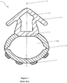
- Figure 1 shows a prior art seal 1, more precisely from document EP1651914 , comprising a first chamber C1 bonded to a second chamber C2.
- the first chamber C1 is provided with latching elements 4 configured to be latched in an associated groove provided in the frame of a sliding cover (not shown in the figure), and the second chamber C2 is elastic/deformable and provided with strips 7 bonded along its outer surface.
- the second chamber C2 is further provided with folding lines 8, having the function of a hinge, that allow the deformation of the second chamber C2 as a result of the contact pressure generated by the sliding cover.
- the seal 1 may be manufactured of various plastic materials having preferred physico-chemical properties.
- the first chamber C1 and the second chamber C2 have a common wall region 3 and a common symmetry axis X.
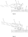
- Figure 2 shows the seal of figure 1 , disadvantageously deformed due to wear. More precisely, the second chamber C2 is deformed such that the contact between the seal 1 and the sliding surface S is no longer accomplished on two or more of the strips 7 (situation in which the sealing is a proper one) but exclusively on the folding lines 8 zones. In other words, the inappropriate deformation of the second chamber C2 consists in the convex shape on which the strips 7 are arranged.
- Figure 3 (a cross section view in a plane perpendicular to the seal's length) shows a seal according to the invention, comprising:
- the seal according to the invention from Figure 3 has the common wall 3 provided with a substantially U-shape when seen in cross-section in a plane perpendicular to the length of the seal 1, such that:
- Figure 4 shows a seal according to the invention, mounted in a sliding element 2 and in contact with a sliding rail S arranged in a plane parallel to the plane of the sliding element 2.
- the latching elements 4 are latched in an associated groove 5 provided in a frame 6 of the sliding element 2.
- the sliding element 2 may be, for example, the cover of a refrigerating container.
- At least one of the sealing elements 7 is in contact with and pressed to the sliding rail S, the pressing force applied to said at least one sealing element 7 thus ensuring the deformation of the second chamber C2 such that the common wall 3 is in contact, over its entire length, with the inner surface of the second chamber C2, thus dividing the second chamber C2 into two separate rooms C21, C22, isolated from one another.
- the U-shape of the common wall 3 eliminates the possibility of a disadvantageous deformation (similar to the one shown in Figure 2 ) of the chamber C2.
- the exterior of the room C21 is in contact with the air outside the refrigerating device and the exterior of the room C22 is in contact with the air inside the refrigerating device.
- Figure 5 is similar to Figure 4 , the difference between the two figures being that the sliding rail S from Figure 5 is arranged in a plane non-parallel to the plane of the sliding element 2.
- Both first chamber C1 and second chamber C2 preferably have the wall thickness of about 1.5 mm, except for the regions of the folding grooves 8 where the wall thickness is about 0.5 mm.
- the first chamber C1 is preferably made of T.R.T. rubber having Shore hardness 90.
- the second chamber C2 is preferably made of T.R.T. rubber having Shore hardness 60.
- the parallel strips 7 are preferably made of H.D.P.E.
Landscapes
- Engineering & Computer Science (AREA)
- General Engineering & Computer Science (AREA)
- Mechanical Engineering (AREA)
- Chemical & Material Sciences (AREA)
- Combustion & Propulsion (AREA)
- Physics & Mathematics (AREA)
- Thermal Sciences (AREA)
- Sealing Devices (AREA)
Abstract
Seal (1) for a sliding element (2), comprising:
- a first chamber (C1) and a second chamber (C2), arranged inside the seal (1) and separated by a common wall (3), wherein the first chamber (C1) and the second chamber (C2) have a common symmetry axis (X) perpendicular to the length of the seal (1);
- latching elements (4)
- sealing elements (7)
- two parallel folding grooves (8) capable to ensure the deformation of the second chamber (C2) when applying an external pressure to the sealing elements (7);
- the common wall (3) has a substantially U-shape when seen in cross-section in a plane perpendicular to the length of the seal (1), such that in the region of the common wall (3), the contour of the first chamber (C1) has a convex shape and the contour of the second chamber (C2) has a concave shape.
- a first chamber (C1) and a second chamber (C2), arranged inside the seal (1) and separated by a common wall (3), wherein the first chamber (C1) and the second chamber (C2) have a common symmetry axis (X) perpendicular to the length of the seal (1);
- latching elements (4)
- sealing elements (7)
- two parallel folding grooves (8) capable to ensure the deformation of the second chamber (C2) when applying an external pressure to the sealing elements (7);
- the common wall (3) has a substantially U-shape when seen in cross-section in a plane perpendicular to the length of the seal (1), such that in the region of the common wall (3), the contour of the first chamber (C1) has a convex shape and the contour of the second chamber (C2) has a concave shape.
Description
- The invention relates to a seal for a sliding element, in particular for a sliding cover or for a sliding shelf of refrigerating device.
- Prior art document
EP1651914 discloses a seal embodiment (seeFigure 1 ) for a sliding cover of refrigerating device. Theseal 1 comprises a first chamber C1 bonded to a second chamber C2, the two chambers being separated by acommon wall 3. The first chamber C1 is provided withlatching elements 4 configured to be latched in an associated groove provided in the frame of the sliding cover, and the second chamber C2 is elastic/deformable and provided withstrips 7 bonded along its outer surface. The second chamber C2 is further provided withhinges 8 that allow the deformation of the second chamber as a result of the contact pressure generated by the sliding cover, wherein the seal may be manufactured of various plastic materials having preferred physico-chemical properties. Theseal 1 has a vertical symmetry axis X. The seal provides a good sliding, the necessary force for moving the sliding cover being small, such that a user perceives the opening/closing of the sliding cover as an easy operation. - It is known that a good sealing is ensured only while the strips on the second chamber are in contact with the rails on which the cover is sliding.
The disadvantage of the seal disclosed inEP16519140 Figure 2 , where the deformation of the second chamber is such that the strips are no longer in contact with the sliding rails, thus leading to a deficient sealing.
Because of the interspaces that are formed due to the defective deformation of the seal, an air exchange takes place between the surrounding environment and the refrigerated space, process during which warmer outer air enters the refrigerated space, thus occurring energy dissipation effects, and consequently reducing the efficiency of the refrigerating device. - The present invention has the purpose to provide a seal similar to the one disclosed in
EP1651914 , to keep all the advantages thereof, but to eliminate all above mentioned disadvantages. - The seal for a sliding element, according to the invention, comprises:
- a first chamber, arranged inside the seal and extending along the whole length of the seal;
- a second chamber, arranged inside the seal and extending along the whole length of the seal;
- the first chamber and the second chamber being separated by a common wall;
- the first chamber and the second chamber having a common simmetry axis perpendicular to the length of the seal;
- latching elements provided on the outer surface of the first chamber, and configured to be latched in an associated groove provided in a frame of the sliding element;
- sealing elements provided on the outer surface of the seal on the second chamber, opposed to the latching elements;
- two parallel folding grooves, arranged along the second chamber and symmetrically in respect to the common symmetry axis, said folding grooves being capable to ensure the deformation of the second chamber when applying an external pressure to the sealing elements;
- the common wall has a substantially U-shape when seen in cross-section in a plane perpendicular to the length of the seal, such that:
- the common wall extends inside the second chamber;
- when seen in said cross-section, in the region of the common wall, the contour of the first chamber has a convex shape and the contour of the second chamber has a concave shape;
- when at least one of the sealing elements is in contact with and pressed to a sliding rail, the second chamber is capable to adopt a deformed position in which the common wall is in contact, over its entire length, with the inner surface of the second chamber, thus dividing the second chamber into two separate rooms, isolated from one another.
- By sliding element is meant, for example, a sliding cover or a sliding shelf.
- The invention will be better understood from the following embodiment, explained in detail and based on the drawings, that show:
-
Figure 1 : a seal according to the closest prior art; -
Figure 2 : the seal offigure 1 , disadvantageously deformed due to wear; -
Figure 3 : seal according to the invention (not deformed); -
Figure 4 : seal according to the invention, mounted in a sliding element and in contact with a sliding rail arranged in a plane parallel to the plane of the sliding element; -
Figure 5 : seal according to the invention, mounted in a sliding element and in contact with a sliding rail arranged in a plane non-parallel to the plane of the sliding element; -
Figure 1 shows aprior art seal 1, more precisely from documentEP1651914 , comprising a first chamber C1 bonded to a second chamber C2. The first chamber C1 is provided withlatching elements 4 configured to be latched in an associated groove provided in the frame of a sliding cover (not shown in the figure), and the second chamber C2 is elastic/deformable and provided withstrips 7 bonded along its outer surface. The second chamber C2 is further provided withfolding lines 8, having the function of a hinge, that allow the deformation of the second chamber C2 as a result of the contact pressure generated by the sliding cover. Theseal 1 may be manufactured of various plastic materials having preferred physico-chemical properties. The first chamber C1 and the second chamber C2 have acommon wall region 3 and a common symmetry axis X. -
Figure 2 shows the seal offigure 1 , disadvantageously deformed due to wear. More precisely, the second chamber C2 is deformed such that the contact between theseal 1 and the sliding surface S is no longer accomplished on two or more of the strips 7 (situation in which the sealing is a proper one) but exclusively on thefolding lines 8 zones. In other words, the inappropriate deformation of the second chamber C2 consists in the convex shape on which thestrips 7 are arranged. - As a matter of fact, if said seal is used to seal a container, the wear of the seal will lead to a defective sealing and implicitly to a defective thermal insulation of the inside of the container in respect to the outer atmosphere.
-
Figure 3 (a cross section view in a plane perpendicular to the seal's length) shows a seal according to the invention, comprising: - a first chamber C1, arranged inside the
seal 1 and extending along the whole length of the seal 1 (in other words, the length of the first chamber C1 coincides with the length of the seal 1); - a second chamber C2, arranged inside the
seal 1 and extending along the whole length of the seal 1 (in other words, the length of the second chamber C2 coincides with the length of the seal 1);- wherein the first chamber C1 and the second chamber C2 are separated by a
common wall 3; - wherein the first chamber C1 and the second chamber C2 have a common simmetry axis X perpendicular to the length of the
seal 1;
- wherein the first chamber C1 and the second chamber C2 are separated by a
- latching elements 4 (preferably consisting of fixing tabs symmetrically arranged in respect to the common symmetry axis X) provided on the outer surface of the first chamber C1, and configured to be latched in an associated groove provided in a frame of a sliding element;
- sealing elements 7 (preferably consisting of parallel strips of plastic material, extending along the whole length of the second chamber C2) provided on the outer surface of the
seal 1 on the second chamber C2, opposed to thelatching elements 4; - two
parallel folding grooves 8, arranged along the second chamber C2 and symmetrically in respect to the common symmetry axis X, saidfolding grooves 8 being capable to ensure the deformation of the second chamber C2 when applying an external pressure to thesealing elements 7. - In contrast to the seal from
Figure 1 , the seal according to the invention fromFigure 3 has thecommon wall 3 provided with a substantially U-shape when seen in cross-section in a plane perpendicular to the length of theseal 1, such that: - the
common wall 3 extends inside the second chamber C2; - when seen in said cross-section, in the region of the
common wall 3, the contour of the first chamber C1 has a convex shape and the contour of the second chamber C2 has a concave shape; - when at least one of the
sealing elements 7 is in contact with and pressed to a sliding rail S (shown only inFigures 4 and 5 ), the second chamber C2 is capable to adopt a deformed position in which thecommon wall 3 is in contact, over its entire length, with the inner surface of the second chamber C2, thus dividing the second chamber C2 into two separate rooms C21, C22 (shown only inFigures 4 and 5 ), isolated from one another. -
Figure 4 shows a seal according to the invention, mounted in asliding element 2 and in contact with a sliding rail S arranged in a plane parallel to the plane of thesliding element 2. Thelatching elements 4 are latched in an associatedgroove 5 provided in aframe 6 of thesliding element 2.
Thesliding element 2 may be, for example, the cover of a refrigerating container.
At least one of thesealing elements 7 is in contact with and pressed to the sliding rail S, the pressing force applied to said at least onesealing element 7 thus ensuring the deformation of the second chamber C2 such that thecommon wall 3 is in contact, over its entire length, with the inner surface of the second chamber C2, thus dividing the second chamber C2 into two separate rooms C21, C22, isolated from one another. - The U-shape of the
common wall 3 eliminates the possibility of a disadvantageous deformation (similar to the one shown inFigure 2 ) of the chamber C2. - The exterior of the room C21 is in contact with the air outside the refrigerating device and the exterior of the room C22 is in contact with the air inside the refrigerating device.
- The transformation of the second chamber C2 into two separate isolated rooms C21, C22, has as direct consequence a better thermal insulation of the inside of the refrigerating device.
-
Figure 5 is similar toFigure 4 , the difference between the two figures being that the sliding rail S fromFigure 5 is arranged in a plane non-parallel to the plane of thesliding element 2. - The behaviour of the
seal 1 fromFigure 5 is identical to the one described in case ofFigure 4 . - Both first chamber C1 and second chamber C2 preferably have the wall thickness of about 1.5 mm, except for the regions of the
folding grooves 8 where the wall thickness is about 0.5 mm. - The first chamber C1 is preferably made of T.R.T. rubber having Shore hardness 90. The second chamber C2 is preferably made of T.R.T. rubber having Shore hardness 60. The
parallel strips 7 are preferably made of H.D.P.E. - Although only one embodiment was disclosed in the description, the present invention is not limited exclusively to said embodiment and covers all equivalents of the disclosed means and of the combinations thereof, as long as said means perform the same function.
Claims (6)
- Seal (1) for a sliding element (2), comprising:- a first chamber (C1), arranged inside the seal (1) and extending along the whole length of the seal (1);- a second chamber (C2), arranged inside the seal (1) and extending along the whole length of the seal (1);- the first chamber (C1) and the second chamber (C2) being separated by a common wall (3);- the first chamber (C1) and the second chamber (C2) having a common simmetry axis (X) perpendicular to the length of the seal (1);- latching elements (4) provided on the outer surface of the first chamber (C1), and configured to be latched in an associated groove (5) provided in a frame (6) of the sliding element (2);- sealing elements (7) provided on the outer surface of the seal (1) on the second chamber (C2), opposed to the latching elements (4);- two parallel folding grooves (8), arranged along the second chamber (C2) and symmetrically in respect to the common symmetry axis (X), said folding grooves (8) being capable to ensure the deformation of the second chamber (C2) when applying an external pressure to the sealing elements (7);
characterized in that
the common wall (3) has a substantially U-shape when seen in cross-section in a plane perpendicular to the length of the seal (1), such that:- the common wall (3) extends inside the second chamber (C2);- when seen in said cross-section, in the region of the common wall (3) the contour of the first chamber (C1) has a convex shape and the contour of the second chamber (C2) has a concave shape;- when at least one of the sealing elements (7) is in contact with and pressed to a sliding rail (S), the second chamber (C2) is capable to adopt a deformed position in which the common wall (3) is in contact, over its entire length, with the inner surface of the second chamber (C2), thus dividing the second chamber (C2) into two separate rooms (C21, C22), isolated from one another. - Seal (1) according to claim 1, characterized in that the latching elements (4) are fixing protuberances (4) symmetrically arranged in respect to the common symmetry axis (X).
- Seal (1) according to claims 1-2, characterized in that the sealing elements (7) are parallel strips (7) of plastic material, extending along the whole length of the second chamber (C2).
- Seal (1) according to claims 1-3, characterized in that the first chamber (C1) and the second chamber (C2) have a wall thickness of about 1.5 mm, except for the regions of the folding grooves (8) where the wall thickness is about 0.5 mm.
- Seal (1) according to claims 3-4, characterized in that the first chamber (C1) is made of T.R.T. rubber having Shore hardness 90, the second chamber (C2) is made of T.R.T. rubber having Shore hardness 60, and the parallel strips (7) are made of H.D.P.E.
- Sliding cover or sliding shelf of a refrigerating device, provided with a seal according to one or more of the previous claims 1 to 5.
Priority Applications (1)
| Application Number | Priority Date | Filing Date | Title |
|---|---|---|---|
| EP19464004.1A EP3708880A1 (en) | 2019-03-12 | 2019-03-12 | Seal for a sliding element |
Applications Claiming Priority (1)
| Application Number | Priority Date | Filing Date | Title |
|---|---|---|---|
| EP19464004.1A EP3708880A1 (en) | 2019-03-12 | 2019-03-12 | Seal for a sliding element |
Publications (1)
| Publication Number | Publication Date |
|---|---|
| EP3708880A1 true EP3708880A1 (en) | 2020-09-16 |
Family
ID=66092269
Family Applications (1)
| Application Number | Title | Priority Date | Filing Date |
|---|---|---|---|
| EP19464004.1A Withdrawn EP3708880A1 (en) | 2019-03-12 | 2019-03-12 | Seal for a sliding element |
Country Status (1)
| Country | Link |
|---|---|
| EP (1) | EP3708880A1 (en) |
Citations (2)
| Publication number | Priority date | Publication date | Assignee | Title |
|---|---|---|---|---|
| US3952455A (en) * | 1975-01-20 | 1976-04-27 | The Pantasote Company | Sealing gasket |
| DE20312327U1 (en) * | 2003-08-09 | 2003-10-16 | REHAU AG + Co., 95111 Rehau | Sealing profile for a cooling device sliding cover |
-
2019
- 2019-03-12 EP EP19464004.1A patent/EP3708880A1/en not_active Withdrawn
Patent Citations (3)
| Publication number | Priority date | Publication date | Assignee | Title |
|---|---|---|---|---|
| US3952455A (en) * | 1975-01-20 | 1976-04-27 | The Pantasote Company | Sealing gasket |
| DE20312327U1 (en) * | 2003-08-09 | 2003-10-16 | REHAU AG + Co., 95111 Rehau | Sealing profile for a cooling device sliding cover |
| EP1651914A1 (en) | 2003-08-09 | 2006-05-03 | REHAU AG + Co | Sealing profile for a sliding cover of a cooling device |
Similar Documents
| Publication | Publication Date | Title |
|---|---|---|
| CN104185714B (en) | Be used for profiled spacer and the hollow glass unit of the spacing frame of the hollow glass unit with clearance component | |
| US6266940B1 (en) | Insert for glazing unit | |
| CA2185464C (en) | Edge seal gasket assembly for a multiple glazing unit | |
| US6517150B2 (en) | Plastic cover for motor vehicles | |
| US20030111802A1 (en) | Sealing member having magnet | |
| EP1431501A3 (en) | Sliding door assembly | |
| US20070077376A1 (en) | Double glazing | |
| EP1025330B1 (en) | Seal | |
| AT9452U1 (en) | SEALING PROFILE FOR A REFRIGERATOR BRAKE COVER | |
| CN101065628B (en) | Refrigerator and/or freezer | |
| US7650719B2 (en) | Vehicle window seal | |
| GB2198621A (en) | Baking oven door with viewing window | |
| EP3877709B1 (en) | Freezers and refrigerators | |
| US20260104091A1 (en) | Sealing Profile | |
| JP2021105503A (en) | refrigerator | |
| KR20040065211A (en) | Coke oven door with wraparound gas channel and membrane | |
| JPH11294938A (en) | refrigerator | |
| RU36646U1 (en) | SEAL PROFILE FOR MOBILE GLASS WINDOW DOOR WINDOW | |
| JP2805445B2 (en) | Airtight container door | |
| CN100383436C (en) | Sealing ring and insulating glazing incorporating such a sealing ring | |
| JP4079562B2 (en) | Sheet glass holding member | |
| GB2066881A (en) | Improvements in and relating to sealing arrangements | |
| US20230235944A1 (en) | Cooling Unit | |
| EP1382924A1 (en) | Sealing device particularly for doors of refrigerators, freezers and the like | |
| RU2236355C2 (en) | Automobile sliding glass sealing strip |
Legal Events
| Date | Code | Title | Description |
|---|---|---|---|
| PUAI | Public reference made under article 153(3) epc to a published international application that has entered the european phase |
Free format text: ORIGINAL CODE: 0009012 |
|
| STAA | Information on the status of an ep patent application or granted ep patent |
Free format text: STATUS: THE APPLICATION HAS BEEN PUBLISHED |
|
| AK | Designated contracting states |
Kind code of ref document: A1 Designated state(s): AL AT BE BG CH CY CZ DE DK EE ES FI FR GB GR HR HU IE IS IT LI LT LU LV MC MK MT NL NO PL PT RO RS SE SI SK SM TR |
|
| AX | Request for extension of the european patent |
Extension state: BA ME |
|
| STAA | Information on the status of an ep patent application or granted ep patent |
Free format text: STATUS: THE APPLICATION IS DEEMED TO BE WITHDRAWN |
|
| 18D | Application deemed to be withdrawn |
Effective date: 20210317 |