EP3708836A1 - Air compressor and air compressor control method - Google Patents
Air compressor and air compressor control method Download PDFInfo
- Publication number
- EP3708836A1 EP3708836A1 EP18875396.6A EP18875396A EP3708836A1 EP 3708836 A1 EP3708836 A1 EP 3708836A1 EP 18875396 A EP18875396 A EP 18875396A EP 3708836 A1 EP3708836 A1 EP 3708836A1
- Authority
- EP
- European Patent Office
- Prior art keywords
- electric motor
- current
- rotational speed
- supply circuit
- oil
- Prior art date
- Legal status (The legal status is an assumption and is not a legal conclusion. Google has not performed a legal analysis and makes no representation as to the accuracy of the status listed.)
- Withdrawn
Links
Images




Classifications
-
- F—MECHANICAL ENGINEERING; LIGHTING; HEATING; WEAPONS; BLASTING
- F04—POSITIVE - DISPLACEMENT MACHINES FOR LIQUIDS; PUMPS FOR LIQUIDS OR ELASTIC FLUIDS
- F04B—POSITIVE-DISPLACEMENT MACHINES FOR LIQUIDS; PUMPS
- F04B49/00—Control, e.g. of pump delivery, or pump pressure of, or safety measures for, machines, pumps, or pumping installations, not otherwise provided for, or of interest apart from, groups F04B1/00 - F04B47/00
- F04B49/02—Stopping, starting, unloading or idling control
- F04B49/03—Stopping, starting, unloading or idling control by means of valves
-
- F—MECHANICAL ENGINEERING; LIGHTING; HEATING; WEAPONS; BLASTING
- F04—POSITIVE - DISPLACEMENT MACHINES FOR LIQUIDS; PUMPS FOR LIQUIDS OR ELASTIC FLUIDS
- F04B—POSITIVE-DISPLACEMENT MACHINES FOR LIQUIDS; PUMPS
- F04B35/00—Piston pumps specially adapted for elastic fluids and characterised by the driving means to their working members, or by combination with, or adaptation to, specific driving engines or motors, not otherwise provided for
- F04B35/04—Piston pumps specially adapted for elastic fluids and characterised by the driving means to their working members, or by combination with, or adaptation to, specific driving engines or motors, not otherwise provided for the means being electric
-
- F—MECHANICAL ENGINEERING; LIGHTING; HEATING; WEAPONS; BLASTING
- F04—POSITIVE - DISPLACEMENT MACHINES FOR LIQUIDS; PUMPS FOR LIQUIDS OR ELASTIC FLUIDS
- F04B—POSITIVE-DISPLACEMENT MACHINES FOR LIQUIDS; PUMPS
- F04B39/00—Component parts, details, or accessories, of pumps or pumping systems specially adapted for elastic fluids, not otherwise provided for in, or of interest apart from, groups F04B25/00 - F04B37/00
- F04B39/02—Lubrication
-
- F—MECHANICAL ENGINEERING; LIGHTING; HEATING; WEAPONS; BLASTING
- F04—POSITIVE - DISPLACEMENT MACHINES FOR LIQUIDS; PUMPS FOR LIQUIDS OR ELASTIC FLUIDS
- F04B—POSITIVE-DISPLACEMENT MACHINES FOR LIQUIDS; PUMPS
- F04B39/00—Component parts, details, or accessories, of pumps or pumping systems specially adapted for elastic fluids, not otherwise provided for in, or of interest apart from, groups F04B25/00 - F04B37/00
- F04B39/06—Cooling; Heating; Prevention of freezing
- F04B39/062—Cooling by injecting a liquid in the gas to be compressed
-
- F—MECHANICAL ENGINEERING; LIGHTING; HEATING; WEAPONS; BLASTING
- F04—POSITIVE - DISPLACEMENT MACHINES FOR LIQUIDS; PUMPS FOR LIQUIDS OR ELASTIC FLUIDS
- F04B—POSITIVE-DISPLACEMENT MACHINES FOR LIQUIDS; PUMPS
- F04B49/00—Control, e.g. of pump delivery, or pump pressure of, or safety measures for, machines, pumps, or pumping installations, not otherwise provided for, or of interest apart from, groups F04B1/00 - F04B47/00
- F04B49/06—Control using electricity
- F04B49/065—Control using electricity and making use of computers
-
- F—MECHANICAL ENGINEERING; LIGHTING; HEATING; WEAPONS; BLASTING
- F04—POSITIVE - DISPLACEMENT MACHINES FOR LIQUIDS; PUMPS FOR LIQUIDS OR ELASTIC FLUIDS
- F04C—ROTARY-PISTON, OR OSCILLATING-PISTON, POSITIVE-DISPLACEMENT MACHINES FOR LIQUIDS; ROTARY-PISTON, OR OSCILLATING-PISTON, POSITIVE-DISPLACEMENT PUMPS
- F04C28/00—Control of, monitoring of, or safety arrangements for, pumps or pumping installations specially adapted for elastic fluids
- F04C28/06—Control of, monitoring of, or safety arrangements for, pumps or pumping installations specially adapted for elastic fluids specially adapted for stopping, starting, idling or no-load operation
-
- F—MECHANICAL ENGINEERING; LIGHTING; HEATING; WEAPONS; BLASTING
- F04—POSITIVE - DISPLACEMENT MACHINES FOR LIQUIDS; PUMPS FOR LIQUIDS OR ELASTIC FLUIDS
- F04B—POSITIVE-DISPLACEMENT MACHINES FOR LIQUIDS; PUMPS
- F04B2201/00—Pump parameters
- F04B2201/04—Carter parameters
- F04B2201/0402—Lubricating oil temperature
-
- F—MECHANICAL ENGINEERING; LIGHTING; HEATING; WEAPONS; BLASTING
- F04—POSITIVE - DISPLACEMENT MACHINES FOR LIQUIDS; PUMPS FOR LIQUIDS OR ELASTIC FLUIDS
- F04B—POSITIVE-DISPLACEMENT MACHINES FOR LIQUIDS; PUMPS
- F04B2203/00—Motor parameters
- F04B2203/02—Motor parameters of rotating electric motors
- F04B2203/0202—Voltage
-
- F—MECHANICAL ENGINEERING; LIGHTING; HEATING; WEAPONS; BLASTING
- F04—POSITIVE - DISPLACEMENT MACHINES FOR LIQUIDS; PUMPS FOR LIQUIDS OR ELASTIC FLUIDS
- F04B—POSITIVE-DISPLACEMENT MACHINES FOR LIQUIDS; PUMPS
- F04B2203/00—Motor parameters
- F04B2203/02—Motor parameters of rotating electric motors
- F04B2203/0209—Rotational speed
-
- F—MECHANICAL ENGINEERING; LIGHTING; HEATING; WEAPONS; BLASTING
- F04—POSITIVE - DISPLACEMENT MACHINES FOR LIQUIDS; PUMPS FOR LIQUIDS OR ELASTIC FLUIDS
- F04B—POSITIVE-DISPLACEMENT MACHINES FOR LIQUIDS; PUMPS
- F04B2205/00—Fluid parameters
- F04B2205/09—Flow through the pump
Definitions
- the present invention relates to an air compressor.
- Patent Document 1 discloses that a star time is derived based on a temperature of an oil that lubricates a compressor body in a compressor including a star-delta circuit that supplies a current to an electric motor.
- Patent Document 1 JP 2015-78607 A
- Patent Document 1 does not disclose means for reducing a load torque required to start the compressor.
- An object of the present invention is to reduce a load torque required to start a compressor.
- An aspect of the present invention provides an air compressor including a compressor body compressing an air sucked from a suction port and discharges the compressed air, an electric motor driving the compressor body, a current supply circuit receiving a power from a power supply and then supplying a current to the electric motor, the current supply circuit being switchable between a steady operation mode in which a rated voltage of the power supply is applied to the electric motor and a start mode in which a voltage lower than the rated voltage is applied to the electric motor, an intake adjustment valve being switchable between an opened state in which the suction of the air from the suction port is executable and a closed state in which the suction of the air from the suction port is blocked, and a controller controlling the modes of the current supply circuit and the opened and closed states of the intake adjustment valve.
- the controller determines whether or not a rotational speed of the electric motor reaches a rated rotational speed, closes the intake adjustment valve and sets the current supply circuit to the start mode for a period from a start time when the supply of the current to the electric motor is started to a steady operation start time when it is determined that the rotational speed of the electric motor reaches the rated rotational speed, and switches the current supply circuit to the steady operation mode and opens the intake adjustment valve in synchronization with the switching for a period after the normal operation start time.
- the intake adjustment valve is closed for a period (start-up period) in which the voltage to be applied to the electric motor is lower than the rated voltage before the rotational speed of the electric motor reaches the rated rotational speed after a start time when the supply of the current to the electric motor is started. That is, for the start-up period, the suction of the air from the suction port is blocked, and the air is not supplied to the compressor body. Therefore, for the start-up period, the torque required for the compressor body to compress the air becomes unnecessary, and the load torque required for starting the electric motor can be reduced. Therefore, the rotation of the electric motor can be prevented from stalling, and the electric motor can be stably started.
- the air compressor may be an oil-cooled type, and may further include an oil separating and collecting device that separates a lubricating oil from the compressed air discharged from the compressor body, and collects the separated lubricating oil.
- the controller may decide a start-up period based on at least one of a temperature of the lubricating oil within the oil separating and collecting device and a temperature of an oil within an oil supply line through which the oil within the oil separating and collecting device is supplied to the compressor body, and may determine that the rotational speed of the electric motor reaches the rated rotational speed when the start-up period elapses after the start time.
- the viscosity of the lubricating oil becomes higher as the temperature of the lubricating oil becomes lower. Therefore, when the temperature is low, the load torque required to start the electric motor is large, and the time required for the rotational speed of the electric motor to reach the rated rotational speed is lengthened.
- a starter which is the current supply circuit is switched to the steady operation mode in which the rated voltage of the power supply is applied to the electric motor even though the rotational speed of the electric motor does not reach the rated rotational speed (for example, when a contactor of a star-delta starter is switched from a star connection to a delta connection), a large current flows through the starter and the electric motor.
- the supply of the current to the electric motor may be stopped due to a failure of the starter (for example, welding of the contactor) and an overcurrent breaker.
- the current supply circuit can be more reliably switched to the steady operation mode after the rotational speed of the electric motor reaches the rated rotational speed by deciding an appropriate length of the start-up period based on the temperature of the lubricating oil. Therefore, it is possible to prevent the rotation of the electric motor from stalling, and it is possible to stably start the electric motor.
- the air compressor may further include a current measurement unit that measures a value of the current to be supplied to the electric motor, and the controller may determine that the rotational speed of the electric motor reaches the rated rotational speed when the value of the current measured by the current measurement unit is equal to or smaller than a predetermined threshold value after the supply of the current to the electric motor is started.
- the largest current generally flows through the electric motor immediately after the supply of the power to the electric motor is started.
- the acceleration of the electric motor is completed and the rotational speed of the electric motor reaches the rated rotational speed
- the current flowing through the electric motor is decreased, and converges to a substantially constant value.
- This convergence value can be predicted from the specifications of the electric motor. Therefore, when the value of the current flowing through the electric motor is equal to or smaller than the predicted convergence value, it is possible to determine that the rotational speed of the electric motor reaches the rated rotational speed.
- the current supply circuit is more reliably switchable to the steady operation mode after the rotational speed of the electric motor reaches the rated rotational speed by switching the current supply circuit to the steady operation mode when the value of the current flowing through the electric motor is equal to or smaller than the predicted convergence value. Therefore, it is possible to prevent the rotation of the electric motor from stalling due to insufficient acceleration, and it is possible to stably start the electric motor.
- Another aspect of the present invention provides a method for controlling an air compressor that includes a compressor body compressing an air sucked from a suction port and discharges the compressed air, an electric motor driving the compressor body, a current supply circuit receiving a power from a power supply and then supplying a current to the electric motor, the current supply circuit being switchable between a steady operation mode in which a rated voltage of the power supply is applied to the electric motor and a start mode in which a voltage lower than the rated voltage is applied to the electric motor, an intake adjustment valve being switchable between an opened state in which the suction of the air from the suction port is executable and a closed state in which the suction of the air from the suction port is blocked, and a controller controlling the modes of the current supply circuit and the opened and closed states of the intake adjustment valve.
- the method includes closing the intake adjustment valve, and setting the current supply circuit to the start mode, and switching the current supply circuit to the steady operation mode, and opening the intake adjustment valve in synchronization with the switching when it is determined that a rotational speed of the electric motor reaches a rated rotational speed.
- the intake control valve is closed, the current supply circuit is set to the start mode.
- the current supply circuit is set to the steady operation mode, and the intake adjustment valve is opened in synchronization with the switching.
- the load torque required for starting the compressor can be reduced.
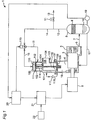
- Fig. 1 illustrates an oil-cooled air compressor 1 according to a first embodiment of the present invention.
- the air compressor 1 includes an intake adjustment valve 100, a compressor body 2 which is a screw compressor, an electric motor 6, an oil separating and collecting device 8, a current supply circuit 21, an oil temperature sensor 19, and a controller 20.
- the compressor body 2 includes a pair of male and female rotors (screw rotors) 3.
- the rotor 3 is driven to rotate by the electric motor 6.
- a suction port 4 for sucking an upstream air is formed in the compressor body 2.
- the compressor body 2 includes a discharge port 5 on a downstream side.
- the discharge port 5 is connected to the oil separating and collecting device 8 via a discharge channel 7.
- the rotor 3 of the compressor body 2 driven to rotate by the electric motor 6 compresses the air supplied from the suction port 4, and discharges the compressed air to the discharge port 5.
- the compressed air discharged from the discharge port 5 contains a large amount of oil.
- This compressed air flows into the oil separating and collecting device 8 through the discharge channel 7.
- the oil separating and collecting device 8 includes an oil separation element 9 disposed at an upper part, and an oil tank 10 disposed at a lower part.
- the oil separation element 9 separates the compressed air containing oil flowed into the oil separating and collecting device 8 into gas and liquid (compressed air and oil).
- the oil separated by the oil separation element 9 is temporarily stored in the oil tank 10 disposed at the lower portion by gravity.
- the compressed air separated from the oil by the oil separation element 9 flows from an outlet of the oil separating and collecting device 8 to an air passage 12. Most of the compressed air supplied to the air passage 12 is supplied to an air passage 13. Part of the compressed air supplied to the air passage 12 is also supplied to an air passage 14.
- the air passage 13 is fluidly connected to a downstream side (not illustrated), and the compressed air is supplied to a supply destination (not illustrated) on the downstream side.
- a pressure holding valve 11 that holds a pressure of the compressed air at a predetermined pressure or higher on a primary side is provided at the air passage 13.
- the oil tank 10 of the lower part of the oil separating and collecting device 8 is connected to the compressor body 2 via an oil supply line 17.
- a lubricating oil stored in the oil tank 10 of the oil separating and collecting device 8 flows to the compressor body 2 through the oil supply line 17 due to a pressure difference between the oil separating and collecting device 8 and the compressor body 2.
- the lubricating oil stored in the oil tank 10 of the oil separating and collecting device 8 may be cooled by passing through an oil cooler (not illustrated), and may flow to the compressor body 2.
- the intake adjustment valve 100 is disposed on the upstream side of the compressor body 2, and is connected to the suction port 4 of the compressor body 2 through an intake passage 18.
- the intake adjustment valve 100 includes a suction part 101 and a cylinder part 102 formed above the suction part 101.
- the suction part 101 has an L-shaped suction casing 103.
- the suction casing 103 has an air filter (not illustrated) in contact with an atmosphere, and includes an inlet 106 through which air can be introduced into a suction space portion 105 within the suction casing 103 at one end, and includes an outlet 107 at the other end (a lower end in Fig. 1 ).
- the outlet 107 is fluidly connected to the intake passage 18 connected to the suction port 4 of the compressor body 2.
- the cylinder part 102 has a cylinder casing 104 formed above the suction casing 103.
- the cylinder casing 104 may be formed integrally with the suction casing 103.
- a valve seat 109 that can be sealed by a valve body 108 is formed around the outlet 107.
- the valve body 108 has a plate-like shape that extends in a direction perpendicular to a vertical direction.
- a guide rod 110 extending in the vertical direction is provided at a center of the valve body 108.
- the guide rod 110 passes through a wall of an upper end of the suction casing 103, and extends into the cylinder casing 104.
- a piston member 111 is fixed to an upper end of the guide rod 110 within the cylinder casing 104, for example, by screwing.
- the piston member 111 is attached such that a sidewall within the cylinder casing 104 can be slid up and down.
- the piston member 111 divides a space within the cylinder casing 104 into a lower space portion 112 below the piston member 111 and an upper space portion 113 above the piston member 111.
- the lower space portion 112 and the upper space portion 113 are not fluidly in communication with each other.
- the lower space portion 112 is connected to an air passage 15, and the upper space portion 113 is connected to an air passage 16.
- a coil spring 114 that is wound around the guide rod 110 is attached below the piston member 111 within the cylinder casing 104, that is, in the lower space portion 112.
- the coil spring 114 urges the piston member 111 upward.
- the valve body 108 disposed at a lower end of the guide rod 110 can move up and down. Therefore, when a downward force applied to an upper surface of the piston member 111 becomes larger than an upward force applied to a lower surface of the piston member 111, the guide rod 110 and the valve body 108 move downward together with the piston member 111.
- the air compressor 1 further includes a three-way solenoid valve 115.
- the air passage 14 through which the compressed air from the oil separating and collecting device 8 flows, the air passage 15 connected to the lower space portion 112 of the cylinder casing 104, and the air passage 16 connected to the upper space portion 113 of the cylinder casing 104 are connected to three ports of the three-way solenoid valve 115, respectively.
- the three-way solenoid valve 115 is electrically connected to the controller 20.
- the controller 20 can switch between a first state in which the air passage 16 and the air passage 15 are fluidly connected and a second state in which the air passage 16 and the air passage 14 are fluidly connected by controlling the three-way solenoid valve 115.
- the suction space portion 105 within the suction casing 103 and the intake passage 18 on the downstream side of the intake adjustment valve 100 are fluidly connected via the air passage 116.
- a check valve 117 is attached to the air passage 116.
- the controller 20 sets the three-way solenoid valve 115 to the first state (that is, fluidly connects the air passage 16 and the air passage 14). Therefore, the compressed air from the oil separating and collecting device 8 is supplied to the upper space portion 113, and a pressure within the upper space portion 113 is increased. Accordingly, the downward force applied to the upper surface of the piston member 111 is increased. When this downward force is large than the upward force applied to the lower surface of the piston member 111 which is mainly the urging force of the coil spring 114, the guide rod 110 and the valve body 108 move downward together with the piston member 111.
- the controller 20 sets the three-way solenoid valve 115 to the second state (that is, fluidly connects the air passage 16 and the air passage 15). Therefore, the air within the upper space portion 113 at a high pressure flows into the lower space portion 112, and the pressure within the upper space 113 is decreased. Accordingly, the downward force applied to the upper surface of the piston member 111 is decreased. When this downward force is smaller than the upward force applied to the lower surface of the piston member 111 which is mainly the urging force of the coil spring 114, the guide rod 110 and the valve body 108 move upward together with the piston member 111. Therefore, the gap between the valve body 108 and the valve seat 109 is closed, and the outlet 107 of the intake adjustment valve 100 is closed.
- the intake adjustment valve 100 is switchable between the opened state in which the air can be introduced from the outlet 107 to the suction port 4 and the closed state in which the introduction of the air from the outlet 107 to the suction port 4 is blocked by the controller 20.
- a power is supplied from a power supply 22 to the electric motor 6 via the current supply circuit (starter) 21.
- the current supply circuit 21 is connected to the controller 20.
- a direct starting (full-voltage starting) method which is one of a general starting methods of the motor has a problem that a large current flows when the electric motor is started.
- the starter which is the current supply circuit 21 is provided, and the current supply circuit 21 is switchable between a start mode in which a voltage lower than a rated voltage of the power supply 22 is applied to the electric motor 6 and a steady operation mode in which the rated voltage of the power supply 22 is applied to the electric motor 6 by the controller 20. Further details of an operation of the electric motor 6 at the time of starting will be described below.
- the oil temperature sensor 19 that measures a temperature of the lubricating oil stored in the oil tank 10 is attached to the oil separating and collecting device 8.
- the oil temperature sensor 19 may be attached to the oil supply line 17 and measure the temperature of the lubricating oil in the oil supply line 17.
- the oil temperature sensor 19 may be attached to both the oil separating and collecting device 8 and the oil supply line 17.
- the oil temperature sensor 19 is connected to the controller 20, and thus, the controller 20 can acquire the temperature of the lubricating oil measured by the oil temperature sensor 19.
- step S101 in Fig. 2 the oil temperature sensor 19 measures the temperature of the lubricating oil in the oil tank 10 or the oil supply line 17 of the oil separating and collecting device 8 or both in the oil tank and the oil supply line.
- the controller 20 decides a length of the start-up period based on the temperature of the lubricating oil measured in step S101.
- the length of the start-up period is preset for the assumed temperature of the lubricating oil, and may be selected by the controller 20 according to the temperature of the lubricating oil measured in step S101. Alternatively, the length of the start-up period may be derived by a preprogrammed calculation expression by using the temperature of the lubricating oil measured in step S101. In general, the viscosity of the lubricating oil becomes higher as the temperature of the lubricating oil becomes lower.
- the length of the starting period is generally set so as to be increased as the temperature of the lubricating oil is decreased.
- step S103 the controller 20 sets the intake adjustment valve 100 to the closed state (confirms that the valve is in the closed state). Accordingly, a torque required for the compressor body 2 to compress the air becomes unnecessary, and a load torque required for starting the electric motor 6 can be reduced.
- step S103 is executed after steps S101 and S102, step S103 may be executed before step S101.
- step S104 the controller 20 sets the current supply circuit 21 to the start mode. The current is supplied to the electric motor 6.
- step S105 the controller 20 determines whether or not the start-up period decided in step S102 elapses after the completion of step S104.
- the processing proceeds to step S106.
- a case where the start-up period elapses means that it is determined that the rotational speed of the electric motor 6 reaches the rated rotational speed.
- step S106 the controller 20 switches the current supply circuit 21 to the steady operation mode.
- step S107 the intake adjustment valve 100 is switched to the opened state in synchronization with the switching of the current supply circuit 21 to the steady operation mode in step S106.
- the term "synchronization" used herein includes a case where the switching of the current supply circuit 21 and the switching of the intake adjustment valve 100 are simultaneously performed, but is not limited thereto. Both the switching operations may be performed slightly before and after. That is, the switching of the intake adjustment valve 100 to the opened state may be performed slightly after the switching of the current supply circuit 21 to the steady operation mode, and vice versa. Therefore, step S107 may be performed immediately before step S106.
- the current supply circuit 21 of Fig. 3 is an example of a star-delta circuit which is a starter.
- Fig. 3 also illustrates the electric motor 6 in order to clarify the connection between the current supply circuit 21 and the electric motor 6.
- the power supply 22 (see Fig. 1 ) which is a three-phase AC power supply is connected to an upstream side of the current supply circuit 21 of Fig. 3 .
- the controller 20 can control contactors 31, 32, and 33 such as electromagnetic contactors to switch between a star connection and a delta connection of the star-delta circuit.
- the star-connected current supply circuit 21 corresponds to the start mode of the current supply circuit 21, and the delta-connected current supply circuit 21 corresponds to the steady operation mode of the current supply circuit 21.
- a known star-delta starting method can be applied to the electric motor 6 according to the first embodiment of the present invention.
- the current supply circuit 21 of Fig. 4 corresponds to a known reactor starting method.
- Fig. 4 also illustrates the electric motor 6 in order to clarify the connection between the current supply circuit 21 and the electric motor 6.
- the power supply 22 (see Fig. 1 ) which is a three-phase AC power supply is connected to the upstream side of the current supply circuit 21 of Fig. 4 .
- the controller 20 sets the current supply circuit 21 to the start mode by closing a contactor 41 and opening a contactor 42.
- the reactor is inserted between the power supply 22 and the electric motor 6 in this manner, and thus, a voltage drop occurs due to the reactor. Accordingly, a start current flowing through the electric motor 6 can be reduced.
- the controller 20 closes the contactor 42 and short-circuits the reactor. Therefore, the rated voltage of the power supply 22 is supplied to the electric motor 6.
- a known reactor starting method can be applied to the electric motor 6 according to the first embodiment of the present invention.
- the current supply circuit 21 may have a Korndorfer configuration in which a three-phase autotransformer is inserted between the power supply 22 and the electric motor 6 when the electric motor 6 is started.
- a known Korndorfer starting method can be applied to the electric motor 6 according to the first embodiment of the present invention.
- the torque required for the compressor body 2 to compress the air becomes unnecessary by setting the intake adjustment valve 100 to the closed state. Therefore, the load torque required to start the electric motor 6 can be reduced, and the rotational speed of the electric motor 6 can be more reliably set to the rated rotational speed in the start time decided by using the temperature of the lubricating oil. Therefore, it is possible to prevent the rotation of the electric motor 6 from stalling after switching to the steady operation mode, and it is possible to stably start the electric motor 6.
- Fig. 5 illustrates an air compressor 1 according to a second embodiment of the present invention.
- the same symbols as those in Fig. 1 indicate the same or corresponding parts.
- parts different from those of the first embodiment will be described, and description of other parts will be omitted.
- a current sensor 23 which is a current measurement unit that measures a value of a current supplied to the electric motor 6 is connected to a wiring between the current supply circuit 21 and the electric motor 6.
- the current sensor 23 is connected to the controller 20, and thus, the controller 20 can acquire the current value measured by the current sensor 23.
- the controller 20 acquires the value of the current supplied to the electric motor 6 instead of the temperature of the lubricating oil according to the first embodiment of the present invention.
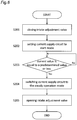
- step S201 in Fig. 6 the controller 20 sets the intake adjustment valve 100 to the closed state (confirms that the valve is in the closed state).
- step S202 the controller 20 sets the current supply circuit 21 to the start mode. The current is supplied to the electric motor 6.
- step S203 the controller 20 determines whether or not the current value measured by the current sensor 23 is equal to or smaller than a predetermined value.
- the largest current generally flows through the electric motor 6 immediately after the supply of the power to the electric motor 6 is started.
- the current flowing through the electric motor 6 is decreased, and converges to a substantially constant value.
- This convergence value can be predicted from the specifications of the electric motor 6. Therefore, when the value of the current flowing through the electric motor 6 is equal to or smaller than the predicted convergence value, it is possible to determine that the rotational speed of the electric motor 6 reaches the rated rotational speed.
- the processing proceeds to step S204.
- step S204 the controller 20 switches the current supply circuit 21 to the steady operation mode.
- step S205 the intake adjustment valve 100 is switched to the opened state in synchronization with the switching of the current supply circuit 21 to the steady operation mode in step S204.
- step S205 may be performed immediately before step S204.
- the air compressor 1 according to the second embodiment of the present invention is not limited to the oil-cooled air compressor 1, but also includes an oil-free air compressor 1.
- the load torque required for starting the electric motor 6 can be reduced by setting the intake adjustment valve 100 to the closed state when the electric motor 6 is started.
- the rotational speed of the electric motor 6 since it is determined whether or not the rotational speed of the electric motor 6 reaches the rated rotational speed by measuring the current flowing through the electric motor 6, it is possible to more reliably prevent the rotation of the electric motor 6 from stalling, and it is possible to stably start the electric motor 6.
- the controller 20 acquires the rotational speed of the electric motor 6 measured by a rotational speed measurement unit (not illustrated).
- Fig. 7 is a flowchart illustrating a start operation of the electric motor 6 according to the modification example of the second embodiment of the present invention.
- the controller 20 determines whether or not the rotational speed of electric motor 6 measured by the rotational speed measurement means reaches the rated rotational speed.
- Steps S301, S302, S304, and S305 other than step S303 of the modification example of the second embodiment of the present invention are the same as the steps of the second embodiment of the present invention.
- Fig. 8 illustrates an air compressor 1 according to a third embodiment of the present invention.
- the same symbols as those in Figs. 1 and 5 indicate the same or corresponding parts.
- parts different from those of the first embodiment and parts different from those of the second embodiment will be described, and description of other parts will be omitted.
- the air compressor 1 includes both the oil temperature sensor 19 and the current sensor 23.
- the oil temperature sensor 19 and the current sensor 23 are connected to the controller 20, and thus, the controller 20 can acquire the temperature of the lubricating oil measured by the oil temperature sensor 19 and the current value measured by the current sensor 23.
- step S401 of Fig. 9 the oil temperature sensor 19 measures the temperature of the lubricating oil in the oil tank 10 or the oil supply line 17 of the oil separating and collecting device 8 or both in the oil tank and the oil supply line.
- step S402 the controller 20 decides a length of the start-up period based on the temperature of the lubricating oil measured in step S401.
- step S403 the controller 20 sets the intake adjustment valve 100 to the closed state (confirms that the valve is in the closed state). Step S403 may be performed before step S401.
- step S404 the controller 20 sets the current supply circuit 21 to the start mode. The current is supplied to the electric motor 6.
- step S405 the controller 20 determines whether or not the start-up period decided in step S402 elapses after the completion of step S404. When the start-up period does not elapse, the processing proceeds to step S406. When the start-up period elapses, the processing proceeds to step S407.
- step S406 the controller 20 determines whether or not the current value measured by the current sensor 23 is equal to or smaller than a predetermined value. When the current value measured by the current sensor 23 is equal to or smaller than the predetermined value, the processing proceeds to step S407, and when the current value is not equal to or smaller than the predetermined value, the processing returns to step S405.
- step S407 the controller 20 switches the current supply circuit 21 to the steady operation mode.
- step S408 the intake adjustment valve 100 is switched to the opened state in synchronization with the switching of the current supply circuit 21 to the steady operation mode in step S407.
- step S408 may be performed immediately before step S407.
- the controller 20 acquires the rotational speed of the electric motor 6 measured by a rotational speed measurement unit (not illustrated).
- Fig. 10 is a flowchart illustrating a start operation of the electric motor 6 according to the modification example of the third embodiment of the present invention.
- the controller 20 determines whether or not the rotational speed of electric motor 6 measured by the rotational speed measurement means is the rated rotational speed.
- Steps S501 to S505, S507, and S508 other than step S506 of the modification example of the third embodiment of the present invention are the same as the steps of the third embodiment of the present invention.
Landscapes
- Engineering & Computer Science (AREA)
- Mechanical Engineering (AREA)
- General Engineering & Computer Science (AREA)
- Computer Hardware Design (AREA)
- Control Of Positive-Displacement Pumps (AREA)
- Applications Or Details Of Rotary Compressors (AREA)
- Motor And Converter Starters (AREA)
Abstract
Description
- The present invention relates to an air compressor.
- When a compressor is started especially at a low temperature, a torque of an electric motor cannot reach a load torque required to start the compressor, there are problems that the rotation of the electric motor stalls and the electric motor cannot be stably started. Patent Document 1 discloses that a star time is derived based on a temperature of an oil that lubricates a compressor body in a compressor including a star-delta circuit that supplies a current to an electric motor.
- Patent Document 1:
JP 2015-78607 A - However, Patent Document 1 does not disclose means for reducing a load torque required to start the compressor.
- An object of the present invention is to reduce a load torque required to start a compressor.
- An aspect of the present invention provides an air compressor including a compressor body compressing an air sucked from a suction port and discharges the compressed air, an electric motor driving the compressor body, a current supply circuit receiving a power from a power supply and then supplying a current to the electric motor, the current supply circuit being switchable between a steady operation mode in which a rated voltage of the power supply is applied to the electric motor and a start mode in which a voltage lower than the rated voltage is applied to the electric motor, an intake adjustment valve being switchable between an opened state in which the suction of the air from the suction port is executable and a closed state in which the suction of the air from the suction port is blocked, and a controller controlling the modes of the current supply circuit and the opened and closed states of the intake adjustment valve. The controller determines whether or not a rotational speed of the electric motor reaches a rated rotational speed, closes the intake adjustment valve and sets the current supply circuit to the start mode for a period from a start time when the supply of the current to the electric motor is started to a steady operation start time when it is determined that the rotational speed of the electric motor reaches the rated rotational speed, and switches the current supply circuit to the steady operation mode and opens the intake adjustment valve in synchronization with the switching for a period after the normal operation start time.
- The intake adjustment valve is closed for a period (start-up period) in which the voltage to be applied to the electric motor is lower than the rated voltage before the rotational speed of the electric motor reaches the rated rotational speed after a start time when the supply of the current to the electric motor is started. That is, for the start-up period, the suction of the air from the suction port is blocked, and the air is not supplied to the compressor body. Therefore, for the start-up period, the torque required for the compressor body to compress the air becomes unnecessary, and the load torque required for starting the electric motor can be reduced. Therefore, the rotation of the electric motor can be prevented from stalling, and the electric motor can be stably started.
- The air compressor may be an oil-cooled type, and may further include an oil separating and collecting device that separates a lubricating oil from the compressed air discharged from the compressor body, and collects the separated lubricating oil. The controller may decide a start-up period based on at least one of a temperature of the lubricating oil within the oil separating and collecting device and a temperature of an oil within an oil supply line through which the oil within the oil separating and collecting device is supplied to the compressor body, and may determine that the rotational speed of the electric motor reaches the rated rotational speed when the start-up period elapses after the start time.
- In general, the viscosity of the lubricating oil becomes higher as the temperature of the lubricating oil becomes lower. Therefore, when the temperature is low, the load torque required to start the electric motor is large, and the time required for the rotational speed of the electric motor to reach the rated rotational speed is lengthened. When a starter which is the current supply circuit is switched to the steady operation mode in which the rated voltage of the power supply is applied to the electric motor even though the rotational speed of the electric motor does not reach the rated rotational speed (for example, when a contactor of a star-delta starter is switched from a star connection to a delta connection), a large current flows through the starter and the electric motor. As a result, the supply of the current to the electric motor may be stopped due to a failure of the starter (for example, welding of the contactor) and an overcurrent breaker. The current supply circuit can be more reliably switched to the steady operation mode after the rotational speed of the electric motor reaches the rated rotational speed by deciding an appropriate length of the start-up period based on the temperature of the lubricating oil. Therefore, it is possible to prevent the rotation of the electric motor from stalling, and it is possible to stably start the electric motor.
- The air compressor may further include a current measurement unit that measures a value of the current to be supplied to the electric motor, and the controller may determine that the rotational speed of the electric motor reaches the rated rotational speed when the value of the current measured by the current measurement unit is equal to or smaller than a predetermined threshold value after the supply of the current to the electric motor is started.
- In the starting of the electric motor, the largest current generally flows through the electric motor immediately after the supply of the power to the electric motor is started. When the acceleration of the electric motor is completed and the rotational speed of the electric motor reaches the rated rotational speed, the current flowing through the electric motor is decreased, and converges to a substantially constant value. This convergence value can be predicted from the specifications of the electric motor. Therefore, when the value of the current flowing through the electric motor is equal to or smaller than the predicted convergence value, it is possible to determine that the rotational speed of the electric motor reaches the rated rotational speed. The current supply circuit is more reliably switchable to the steady operation mode after the rotational speed of the electric motor reaches the rated rotational speed by switching the current supply circuit to the steady operation mode when the value of the current flowing through the electric motor is equal to or smaller than the predicted convergence value. Therefore, it is possible to prevent the rotation of the electric motor from stalling due to insufficient acceleration, and it is possible to stably start the electric motor.
- Another aspect of the present invention provides a method for controlling an air compressor that includes a compressor body compressing an air sucked from a suction port and discharges the compressed air, an electric motor driving the compressor body, a current supply circuit receiving a power from a power supply and then supplying a current to the electric motor, the current supply circuit being switchable between a steady operation mode in which a rated voltage of the power supply is applied to the electric motor and a start mode in which a voltage lower than the rated voltage is applied to the electric motor, an intake adjustment valve being switchable between an opened state in which the suction of the air from the suction port is executable and a closed state in which the suction of the air from the suction port is blocked, and a controller controlling the modes of the current supply circuit and the opened and closed states of the intake adjustment valve. The method includes closing the intake adjustment valve, and setting the current supply circuit to the start mode, and switching the current supply circuit to the steady operation mode, and opening the intake adjustment valve in synchronization with the switching when it is determined that a rotational speed of the electric motor reaches a rated rotational speed. In this method, the intake control valve is closed, the current supply circuit is set to the start mode. When it is determined that the rotational speed of the electric motor reaches the rated rotational speed, the current supply circuit is set to the steady operation mode, and the intake adjustment valve is opened in synchronization with the switching.
- According to the present invention, the load torque required for starting the compressor can be reduced.
-
-
Fig. 1 is a schematic diagram illustrating an air compressor according to a first embodiment of the present invention. -
Fig. 2 is a flowchart illustrating steps for starting an electric motor according to the first embodiment. -
Fig. 3 is a schematic diagram illustrating a specific example of a current supply circuit. -
Fig. 4 is a schematic diagram illustrating another specific example of the current supply circuit. -
Fig. 5 is a schematic diagram illustrating an air compressor according to a second embodiment of the present invention. -
Fig. 6 is a flowchart illustrating steps for starting an electric motor according to the second embodiment. -
Fig. 7 is a flowchart illustrating steps for starting an electric motor according to a modification example of the second embodiment. -
Fig. 8 is a schematic diagram illustrating an air compressor according to a third embodiment of the present invention. -
Fig. 9 is a flowchart illustrating steps for starting an electric motor according to the third embodiment. -
Fig. 10 is a flowchart illustrating steps for starting an electric motor according to a modification example of the third embodiment. -
Fig. 1 illustrates an oil-cooled air compressor 1 according to a first embodiment of the present invention. The air compressor 1 includes anintake adjustment valve 100, a compressor body 2 which is a screw compressor, anelectric motor 6, an oil separating and collectingdevice 8, acurrent supply circuit 21, anoil temperature sensor 19, and acontroller 20. - The compressor body 2 includes a pair of male and female rotors (screw rotors) 3. The rotor 3 is driven to rotate by the
electric motor 6. Asuction port 4 for sucking an upstream air is formed in the compressor body 2. - The compressor body 2 includes a
discharge port 5 on a downstream side. Thedischarge port 5 is connected to the oil separating and collectingdevice 8 via a discharge channel 7. The rotor 3 of the compressor body 2 driven to rotate by theelectric motor 6 compresses the air supplied from thesuction port 4, and discharges the compressed air to thedischarge port 5. - The compressed air discharged from the
discharge port 5 contains a large amount of oil. This compressed air flows into the oil separating and collectingdevice 8 through the discharge channel 7. The oil separating and collectingdevice 8 includes anoil separation element 9 disposed at an upper part, and anoil tank 10 disposed at a lower part. Theoil separation element 9 separates the compressed air containing oil flowed into the oil separating and collectingdevice 8 into gas and liquid (compressed air and oil). The oil separated by theoil separation element 9 is temporarily stored in theoil tank 10 disposed at the lower portion by gravity. - The compressed air separated from the oil by the
oil separation element 9 flows from an outlet of the oil separating and collectingdevice 8 to anair passage 12. Most of the compressed air supplied to theair passage 12 is supplied to anair passage 13. Part of the compressed air supplied to theair passage 12 is also supplied to anair passage 14. Theair passage 13 is fluidly connected to a downstream side (not illustrated), and the compressed air is supplied to a supply destination (not illustrated) on the downstream side. Apressure holding valve 11 that holds a pressure of the compressed air at a predetermined pressure or higher on a primary side is provided at theair passage 13. - The
oil tank 10 of the lower part of the oil separating and collectingdevice 8 is connected to the compressor body 2 via anoil supply line 17. A lubricating oil stored in theoil tank 10 of the oil separating and collectingdevice 8 flows to the compressor body 2 through theoil supply line 17 due to a pressure difference between the oil separating and collectingdevice 8 and the compressor body 2. - In order to prevent a high-temperature lubricating oil from flowing to the compressor body 2, the lubricating oil stored in the
oil tank 10 of the oil separating and collectingdevice 8 may be cooled by passing through an oil cooler (not illustrated), and may flow to the compressor body 2. - The
intake adjustment valve 100 is disposed on the upstream side of the compressor body 2, and is connected to thesuction port 4 of the compressor body 2 through anintake passage 18. Theintake adjustment valve 100 includes asuction part 101 and acylinder part 102 formed above thesuction part 101. - In the illustrated example, the
suction part 101 has an L-shapedsuction casing 103. Thesuction casing 103 has an air filter (not illustrated) in contact with an atmosphere, and includes aninlet 106 through which air can be introduced into asuction space portion 105 within thesuction casing 103 at one end, and includes anoutlet 107 at the other end (a lower end inFig. 1 ). Theoutlet 107 is fluidly connected to theintake passage 18 connected to thesuction port 4 of the compressor body 2. - The
cylinder part 102 has acylinder casing 104 formed above thesuction casing 103. Thecylinder casing 104 may be formed integrally with thesuction casing 103. - A
valve seat 109 that can be sealed by avalve body 108 is formed around theoutlet 107. Thevalve body 108 has a plate-like shape that extends in a direction perpendicular to a vertical direction. Aguide rod 110 extending in the vertical direction is provided at a center of thevalve body 108. Theguide rod 110 passes through a wall of an upper end of thesuction casing 103, and extends into thecylinder casing 104. Apiston member 111 is fixed to an upper end of theguide rod 110 within thecylinder casing 104, for example, by screwing. - The
piston member 111 is attached such that a sidewall within thecylinder casing 104 can be slid up and down. Thepiston member 111 divides a space within thecylinder casing 104 into alower space portion 112 below thepiston member 111 and anupper space portion 113 above thepiston member 111. Thelower space portion 112 and theupper space portion 113 are not fluidly in communication with each other. Thelower space portion 112 is connected to anair passage 15, and theupper space portion 113 is connected to anair passage 16. - A
coil spring 114 that is wound around theguide rod 110 is attached below thepiston member 111 within thecylinder casing 104, that is, in thelower space portion 112. Thecoil spring 114 urges thepiston member 111 upward. - The
valve body 108 disposed at a lower end of theguide rod 110 can move up and down. Therefore, when a downward force applied to an upper surface of thepiston member 111 becomes larger than an upward force applied to a lower surface of thepiston member 111, theguide rod 110 and thevalve body 108 move downward together with thepiston member 111. - In the illustrated example, the air compressor 1 further includes a three-
way solenoid valve 115. Theair passage 14 through which the compressed air from the oil separating and collectingdevice 8 flows, theair passage 15 connected to thelower space portion 112 of thecylinder casing 104, and theair passage 16 connected to theupper space portion 113 of thecylinder casing 104 are connected to three ports of the three-way solenoid valve 115, respectively. The three-way solenoid valve 115 is electrically connected to thecontroller 20. Thecontroller 20 can switch between a first state in which theair passage 16 and theair passage 15 are fluidly connected and a second state in which theair passage 16 and theair passage 14 are fluidly connected by controlling the three-way solenoid valve 115. - In the illustrated example, the
suction space portion 105 within thesuction casing 103 and theintake passage 18 on the downstream side of theintake adjustment valve 100 are fluidly connected via theair passage 116. Acheck valve 117 is attached to theair passage 116. - An operation of setting the
intake adjustment valve 100 to an opened state will be described. Thecontroller 20 sets the three-way solenoid valve 115 to the first state (that is, fluidly connects theair passage 16 and the air passage 14). Therefore, the compressed air from the oil separating and collectingdevice 8 is supplied to theupper space portion 113, and a pressure within theupper space portion 113 is increased. Accordingly, the downward force applied to the upper surface of thepiston member 111 is increased. When this downward force is large than the upward force applied to the lower surface of thepiston member 111 which is mainly the urging force of thecoil spring 114, theguide rod 110 and thevalve body 108 move downward together with thepiston member 111. Therefore, a gap is formed between thevalve body 108 and thevalve seat 109, and theoutlet 107 of theintake adjustment valve 100 is opened. Therefore, the air sucked from theinlet 106 of theintake adjustment valve 100 is supplied to thesuction port 4 of the compressor body 2 through theoutlet 107 of theintake adjustment valve 100 and theintake passage 18. - Next, an operation of setting the
intake adjustment valve 100 to a closed state will be described. Thecontroller 20 sets the three-way solenoid valve 115 to the second state (that is, fluidly connects theair passage 16 and the air passage 15). Therefore, the air within theupper space portion 113 at a high pressure flows into thelower space portion 112, and the pressure within theupper space 113 is decreased. Accordingly, the downward force applied to the upper surface of thepiston member 111 is decreased. When this downward force is smaller than the upward force applied to the lower surface of thepiston member 111 which is mainly the urging force of thecoil spring 114, theguide rod 110 and thevalve body 108 move upward together with thepiston member 111. Therefore, the gap between thevalve body 108 and thevalve seat 109 is closed, and theoutlet 107 of theintake adjustment valve 100 is closed. - As described above, the
intake adjustment valve 100 is switchable between the opened state in which the air can be introduced from theoutlet 107 to thesuction port 4 and the closed state in which the introduction of the air from theoutlet 107 to thesuction port 4 is blocked by thecontroller 20. - A power is supplied from a
power supply 22 to theelectric motor 6 via the current supply circuit (starter) 21. Thecurrent supply circuit 21 is connected to thecontroller 20. A direct starting (full-voltage starting) method which is one of a general starting methods of the motor has a problem that a large current flows when the electric motor is started. In order to prevent this, the starter which is thecurrent supply circuit 21 is provided, and thecurrent supply circuit 21 is switchable between a start mode in which a voltage lower than a rated voltage of thepower supply 22 is applied to theelectric motor 6 and a steady operation mode in which the rated voltage of thepower supply 22 is applied to theelectric motor 6 by thecontroller 20. Further details of an operation of theelectric motor 6 at the time of starting will be described below. - The
oil temperature sensor 19 that measures a temperature of the lubricating oil stored in theoil tank 10 is attached to the oil separating and collectingdevice 8. Alternatively, theoil temperature sensor 19 may be attached to theoil supply line 17 and measure the temperature of the lubricating oil in theoil supply line 17. Alternatively, theoil temperature sensor 19 may be attached to both the oil separating and collectingdevice 8 and theoil supply line 17. Theoil temperature sensor 19 is connected to thecontroller 20, and thus, thecontroller 20 can acquire the temperature of the lubricating oil measured by theoil temperature sensor 19. - Next, the operation of the
electric motor 6 will be described with reference toFig. 2 . Since the steady operation of themotor 6 is known, the description is omitted, and only the operation (start operation) of theelectric motor 6 for a period (start-up period) from a start time when the supply of the current to theelectric motor 6 is started to a steady operation start time when a rotational speed of theelectric motor 6 reaches a rated rotational speed will be described. - First, in step S101 in
Fig. 2 , theoil temperature sensor 19 measures the temperature of the lubricating oil in theoil tank 10 or theoil supply line 17 of the oil separating and collectingdevice 8 or both in the oil tank and the oil supply line. - In the next step S102, the
controller 20 decides a length of the start-up period based on the temperature of the lubricating oil measured in step S101. The length of the start-up period is preset for the assumed temperature of the lubricating oil, and may be selected by thecontroller 20 according to the temperature of the lubricating oil measured in step S101. Alternatively, the length of the start-up period may be derived by a preprogrammed calculation expression by using the temperature of the lubricating oil measured in step S101. In general, the viscosity of the lubricating oil becomes higher as the temperature of the lubricating oil becomes lower. Therefore, when the temperature is low, a load torque required to start theelectric motor 6 is large, and a time required until the rotational speed of theelectric motor 6 reaches the rated rotational speed becomes long. When thecurrent supply circuit 21 is switched to the steady operation mode in which the rated voltage of thepower supply 22 is applied to theelectric motor 6 even though the rotational speed of theelectric motor 6 does not reach the rated rotational speed, a large current flows through theelectric motor 6. As a result, the supply of the current to theelectric motor 6 may be stopped due to a failure of the current supply circuit (starter) 21 and an overcurrent breaker. Therefore, it is possible to more reliably switch thecurrent supply circuit 21 to the steady operation mode after the rotational speed of theelectric motor 6 reaches the rated rotational speed by deciding an appropriate length of the start-up period based on the temperature of the lubricating oil. Therefore, the length of the starting period is generally set so as to be increased as the temperature of the lubricating oil is decreased. - In step S103, the
controller 20 sets theintake adjustment valve 100 to the closed state (confirms that the valve is in the closed state). Accordingly, a torque required for the compressor body 2 to compress the air becomes unnecessary, and a load torque required for starting theelectric motor 6 can be reduced. Although it has been described that step S103 is executed after steps S101 and S102, step S103 may be executed before step S101. - Next, in step S104, the
controller 20 sets thecurrent supply circuit 21 to the start mode. The current is supplied to theelectric motor 6. - In step S105, the
controller 20 determines whether or not the start-up period decided in step S102 elapses after the completion of step S104. When the start-up period elapses, the processing proceeds to step S106. A case where the start-up period elapses means that it is determined that the rotational speed of theelectric motor 6 reaches the rated rotational speed. - In step S106, the
controller 20 switches thecurrent supply circuit 21 to the steady operation mode. - In step S107, the
intake adjustment valve 100 is switched to the opened state in synchronization with the switching of thecurrent supply circuit 21 to the steady operation mode in step S106. The term "synchronization" used herein includes a case where the switching of thecurrent supply circuit 21 and the switching of theintake adjustment valve 100 are simultaneously performed, but is not limited thereto. Both the switching operations may be performed slightly before and after. That is, the switching of theintake adjustment valve 100 to the opened state may be performed slightly after the switching of thecurrent supply circuit 21 to the steady operation mode, and vice versa. Therefore, step S107 may be performed immediately before step S106. - Next, a specific example of the
current supply circuit 21 is illustrated inFigs. 3 and4 . Thecurrent supply circuit 21 ofFig. 3 is an example of a star-delta circuit which is a starter.Fig. 3 also illustrates theelectric motor 6 in order to clarify the connection between thecurrent supply circuit 21 and theelectric motor 6. The power supply 22 (seeFig. 1 ) which is a three-phase AC power supply is connected to an upstream side of thecurrent supply circuit 21 ofFig. 3 . Thecontroller 20 can controlcontactors current supply circuit 21 corresponds to the start mode of thecurrent supply circuit 21, and the delta-connectedcurrent supply circuit 21 corresponds to the steady operation mode of thecurrent supply circuit 21. As described above, a known star-delta starting method can be applied to theelectric motor 6 according to the first embodiment of the present invention. - The
current supply circuit 21 ofFig. 4 corresponds to a known reactor starting method.Fig. 4 also illustrates theelectric motor 6 in order to clarify the connection between thecurrent supply circuit 21 and theelectric motor 6. The power supply 22 (seeFig. 1 ) which is a three-phase AC power supply is connected to the upstream side of thecurrent supply circuit 21 ofFig. 4 . When theelectric motor 6 is started, thecontroller 20 sets thecurrent supply circuit 21 to the start mode by closing acontactor 41 and opening acontactor 42. The reactor is inserted between thepower supply 22 and theelectric motor 6 in this manner, and thus, a voltage drop occurs due to the reactor. Accordingly, a start current flowing through theelectric motor 6 can be reduced. In the steady operation mode, thecontroller 20 closes thecontactor 42 and short-circuits the reactor. Therefore, the rated voltage of thepower supply 22 is supplied to theelectric motor 6. As described above, a known reactor starting method can be applied to theelectric motor 6 according to the first embodiment of the present invention. - Although not illustrated, the
current supply circuit 21 may have a Korndorfer configuration in which a three-phase autotransformer is inserted between thepower supply 22 and theelectric motor 6 when theelectric motor 6 is started. As described above, a known Korndorfer starting method can be applied to theelectric motor 6 according to the first embodiment of the present invention. - As described above, in the first embodiment of the present invention, when the
electric motor 6 is started, the torque required for the compressor body 2 to compress the air becomes unnecessary by setting theintake adjustment valve 100 to the closed state. Therefore, the load torque required to start theelectric motor 6 can be reduced, and the rotational speed of theelectric motor 6 can be more reliably set to the rated rotational speed in the start time decided by using the temperature of the lubricating oil. Therefore, it is possible to prevent the rotation of theelectric motor 6 from stalling after switching to the steady operation mode, and it is possible to stably start theelectric motor 6. -
Fig. 5 illustrates an air compressor 1 according to a second embodiment of the present invention. InFig. 5 , the same symbols as those inFig. 1 indicate the same or corresponding parts. In the following description, in principle, parts different from those of the first embodiment will be described, and description of other parts will be omitted. - A
current sensor 23 which is a current measurement unit that measures a value of a current supplied to theelectric motor 6 is connected to a wiring between thecurrent supply circuit 21 and theelectric motor 6. Thecurrent sensor 23 is connected to thecontroller 20, and thus, thecontroller 20 can acquire the current value measured by thecurrent sensor 23. As described above, in the second embodiment of the present invention, thecontroller 20 acquires the value of the current supplied to theelectric motor 6 instead of the temperature of the lubricating oil according to the first embodiment of the present invention. - Next, a start operation of the
electric motor 6 will be described with reference toFig. 6 . First, in step S201 inFig. 6 , thecontroller 20 sets theintake adjustment valve 100 to the closed state (confirms that the valve is in the closed state). - Next, in step S202, the
controller 20 sets thecurrent supply circuit 21 to the start mode. The current is supplied to theelectric motor 6. - In step S203, the
controller 20 determines whether or not the current value measured by thecurrent sensor 23 is equal to or smaller than a predetermined value. In the starting of theelectric motor 6, the largest current generally flows through theelectric motor 6 immediately after the supply of the power to theelectric motor 6 is started. When the acceleration of themotor 6 is completed and the rotational speed of theelectric motor 6 reaches the rated rotational speed, the current flowing through theelectric motor 6 is decreased, and converges to a substantially constant value. This convergence value can be predicted from the specifications of theelectric motor 6. Therefore, when the value of the current flowing through theelectric motor 6 is equal to or smaller than the predicted convergence value, it is possible to determine that the rotational speed of theelectric motor 6 reaches the rated rotational speed. When the current value measured by thecurrent sensor 23 is equal to or smaller than the predetermined value, the processing proceeds to step S204. - In step S204, the
controller 20 switches thecurrent supply circuit 21 to the steady operation mode. - In step S205, the
intake adjustment valve 100 is switched to the opened state in synchronization with the switching of thecurrent supply circuit 21 to the steady operation mode in step S204. As in the case of the first embodiment of the present invention, step S205 may be performed immediately before step S204. - The air compressor 1 according to the second embodiment of the present invention is not limited to the oil-cooled air compressor 1, but also includes an oil-free air compressor 1.
- As described above, in the second embodiment of the present invention, the load torque required for starting the
electric motor 6 can be reduced by setting theintake adjustment valve 100 to the closed state when theelectric motor 6 is started. In the second embodiment of the present invention, since it is determined whether or not the rotational speed of theelectric motor 6 reaches the rated rotational speed by measuring the current flowing through theelectric motor 6, it is possible to more reliably prevent the rotation of theelectric motor 6 from stalling, and it is possible to stably start theelectric motor 6. - Next, a modification example of the second embodiment of the present invention will be described. In the modification example of the second embodiment of the present invention, the
controller 20 acquires the rotational speed of theelectric motor 6 measured by a rotational speed measurement unit (not illustrated). -
Fig. 7 is a flowchart illustrating a start operation of theelectric motor 6 according to the modification example of the second embodiment of the present invention. In step S303 of the modification example of the second embodiment of the present invention, thecontroller 20 determines whether or not the rotational speed ofelectric motor 6 measured by the rotational speed measurement means reaches the rated rotational speed. Steps S301, S302, S304, and S305 other than step S303 of the modification example of the second embodiment of the present invention are the same as the steps of the second embodiment of the present invention. - As described above, in the modification example of the second embodiment of the present invention, it is possible to more reliably determine whether the rotational speed of the
electric motor 6 reaches the rated rotational speed. Therefore, it is possible to more reliably prevent the rotation of theelectric motor 6 from stalling, and it is possible to stably start theelectric motor 6. -
Fig. 8 illustrates an air compressor 1 according to a third embodiment of the present invention. InFig. 8 , the same symbols as those inFigs. 1 and5 indicate the same or corresponding parts. In the following description, in principle, parts different from those of the first embodiment and parts different from those of the second embodiment will be described, and description of other parts will be omitted. - In the third embodiment of the present invention, the air compressor 1 includes both the
oil temperature sensor 19 and thecurrent sensor 23. Theoil temperature sensor 19 and thecurrent sensor 23 are connected to thecontroller 20, and thus, thecontroller 20 can acquire the temperature of the lubricating oil measured by theoil temperature sensor 19 and the current value measured by thecurrent sensor 23. - Next, a start operation of the
electric motor 6 will be described with reference toFig. 9 . First, in step S401 ofFig. 9 , theoil temperature sensor 19 measures the temperature of the lubricating oil in theoil tank 10 or theoil supply line 17 of the oil separating and collectingdevice 8 or both in the oil tank and the oil supply line. - In the next step S402, the
controller 20 decides a length of the start-up period based on the temperature of the lubricating oil measured in step S401. - In step S403, the
controller 20 sets theintake adjustment valve 100 to the closed state (confirms that the valve is in the closed state). Step S403 may be performed before step S401. - Next, in step S404, the
controller 20 sets thecurrent supply circuit 21 to the start mode. The current is supplied to theelectric motor 6. - In step S405, the
controller 20 determines whether or not the start-up period decided in step S402 elapses after the completion of step S404. When the start-up period does not elapse, the processing proceeds to step S406. When the start-up period elapses, the processing proceeds to step S407. - In step S406, the
controller 20 determines whether or not the current value measured by thecurrent sensor 23 is equal to or smaller than a predetermined value. When the current value measured by thecurrent sensor 23 is equal to or smaller than the predetermined value, the processing proceeds to step S407, and when the current value is not equal to or smaller than the predetermined value, the processing returns to step S405. - In step S407, the
controller 20 switches thecurrent supply circuit 21 to the steady operation mode. - In step S408, the
intake adjustment valve 100 is switched to the opened state in synchronization with the switching of thecurrent supply circuit 21 to the steady operation mode in step S407. As in the cases of the first embodiment and the second embodiment of the present invention, step S408 may be performed immediately before step S407. - Next, a modification example of the third embodiment of the present invention will be described. In the modification example of the third embodiment of the present invention, the
controller 20 acquires the rotational speed of theelectric motor 6 measured by a rotational speed measurement unit (not illustrated). -
Fig. 10 is a flowchart illustrating a start operation of theelectric motor 6 according to the modification example of the third embodiment of the present invention. In step S506 of the modification example of the third embodiment of the present invention, thecontroller 20 determines whether or not the rotational speed ofelectric motor 6 measured by the rotational speed measurement means is the rated rotational speed. Steps S501 to S505, S507, and S508 other than step S506 of the modification example of the third embodiment of the present invention are the same as the steps of the third embodiment of the present invention. -
- 1
- air compressor
- 2
- compressor body
- 3
- rotor
- 4
- suction port
- 5
- discharge port
- 6
- electric motor
- 7
- discharge channel
- 8
- oil separating and collecting device
- 9
- oil separation element
- 10
- oil tank
- 11
- pressure holding valve
- 12 to 16
- air passage
- 17
- oil supply line
- 18
- intake passage
- 19
- oil temperature sensor
- 20
- controller
- 21
- current supply circuit
- 22
- power supply
- 23
- current sensor (current measurement unit)
- 31 to 33
- contactor
- 41, 42
- contactor
- 100
- intake adjustment valve
- 101
- suction part
- 102
- cylinder part
- 103
- suction casing
- 104
- cylinder casing
- 105
- suction space portion
- 106
- inlet
- 107
- outlet
- 108
- valve body
- 109
- valve seat
- 110
- guide rod
- 111
- piston member
- 112
- lower space portion
- 113
- upper space portion
- 114
- coil spring
- 115
- three-way solenoid valve
- 116
- air passage
- 117
- check valve
Claims (4)
- An air compressor comprising:a compressor body compressing an air sucked from a suction port and discharges the compressed air;an electric motor driving the compressor body;a current supply circuit receiving a power from a power supply and then supplying a current to the electric motor, the current supply circuit being switchable between a steady operation mode in which a rated voltage of the power supply is applied to the electric motor and a start mode in which a voltage lower than the rated voltage is applied to the electric motor;an intake adjustment valve being switchable between an opened state in which the suction of the air from the suction port is executable and a closed state in which the suction of the air from the suction port is blocked; anda controller controlling the modes of the current supply circuit and the opened and closed states of the intake adjustment valve,wherein the controller determines whether or not a rotational speed of the electric motor reaches a rated rotational speed,wherein the controller closes the intake adjustment valve and sets the current supply circuit to the start mode for a period from a start time when the supply of the current to the electric motor is started to a steady operation start time when it is determined that the rotational speed of the electric motor reaches the rated rotational speed, andwherein the controller switches the current supply circuit to the steady operation mode and opens the intake adjustment valve in synchronization with the switching for a period after the normal operation start time.
- The air compressor according to claim 1, wherein
the air compressor is an oil-cooled air compressor, and further includes an oil separating and collecting device that separates a lubricating oil from the compressed air discharged from the compressor body, and collects the separated lubricating oil, and
the controller decides a start-up period based on at least one of a temperature of the lubricating oil within the oil separating and collecting device and a temperature of an oil within an oil supply line through which the oil within the oil separating and collecting device is supplied to the compressor body, and determines that the rotational speed of the electric motor reaches the rated rotational speed when the start-up period elapses after the start time. - The air compressor according to claim 1 further comprising a current measurement unit that measures a value of the current to be supplied to the electric motor,
wherein the controller determines that the rotational speed of the electric motor reaches the rated rotational speed when the value of the current measured by the current measurement unit is equal to or smaller than a predetermined threshold value after the supply of the current to the electric motor is started. - A method for controlling an air compressor, the air compressor comprising:a compressor body compressing an air sucked from a suction port and discharges the compressed air;an electric motor driving the compressor body;a current supply circuit receiving a power from a power supply and then supplying a current to the electric motor, the current supply circuit being switchable between a steady operation mode in which a rated voltage of the power supply is applied to the electric motor and a start mode in which a voltage lower than the rated voltage is applied to the electric motor;an intake adjustment valve being switchable between an opened state in which the suction of the air from the suction port is executable and a closed state in which the suction of the air from the suction port is blocked; anda controller controlling the modes of the current supply circuit and the opened and closed states of the intake adjustment valve,the method comprising:closing the intake adjustment valve, and setting the current supply circuit to the start mode; andswitching the current supply circuit to the steady operation mode, and opening the intake adjustment valve in synchronization with the switching when it is determined that a rotational speed of the electric motor reaches a rated rotational speed.
Applications Claiming Priority (2)
| Application Number | Priority Date | Filing Date | Title |
|---|---|---|---|
| JP2017216797A JP6761402B2 (en) | 2017-11-09 | 2017-11-09 | Air compressor and air compressor control method |
| PCT/JP2018/035763 WO2019093007A1 (en) | 2017-11-09 | 2018-09-26 | Air compressor and air compressor control method |
Publications (2)
| Publication Number | Publication Date |
|---|---|
| EP3708836A1 true EP3708836A1 (en) | 2020-09-16 |
| EP3708836A4 EP3708836A4 (en) | 2021-05-19 |
Family
ID=66437727
Family Applications (1)
| Application Number | Title | Priority Date | Filing Date |
|---|---|---|---|
| EP18875396.6A Withdrawn EP3708836A4 (en) | 2017-11-09 | 2018-09-26 | AIR COMPRESSOR AND AIR COMPRESSOR CONTROL PROCESS |
Country Status (6)
| Country | Link |
|---|---|
| EP (1) | EP3708836A4 (en) |
| JP (1) | JP6761402B2 (en) |
| CN (1) | CN111279078B (en) |
| MY (1) | MY203251A (en) |
| SG (1) | SG11202003684VA (en) |
| WO (1) | WO2019093007A1 (en) |
Families Citing this family (5)
| Publication number | Priority date | Publication date | Assignee | Title |
|---|---|---|---|---|
| US11643428B2 (en) | 2018-02-06 | 2023-05-09 | Shanghai Pharmaceuticals Holding Co., Ltd. | Therapeutic drug for neurodegenerative disease and application thereof |
| US12385490B2 (en) * | 2020-09-25 | 2025-08-12 | Hitachi Industrial Equipment Systems Co., Ltd. | Gas compressor |
| CN112879298B (en) * | 2021-01-22 | 2023-03-24 | 重庆开山流体机械有限公司 | Control mechanism of vacuum pumping system |
| CN112879295B (en) * | 2021-01-22 | 2023-03-14 | 重庆开山流体机械有限公司 | Vacuum pumping device |
| CN113107824B (en) * | 2021-03-25 | 2022-11-29 | 浙江志高机械股份有限公司 | Intelligent air supplement system for air compressor of rock drilling machine |
Family Cites Families (5)
| Publication number | Priority date | Publication date | Assignee | Title |
|---|---|---|---|---|
| JPH0979166A (en) * | 1995-09-14 | 1997-03-25 | Hitachi Ltd | air compressor |
| JP3390935B2 (en) * | 1996-10-07 | 2003-03-31 | デンヨー株式会社 | Motor compressor restart time reduction device |
| CN201802600U (en) * | 2010-02-11 | 2011-04-20 | 边雁 | Air compressor |
| JP6009278B2 (en) * | 2012-08-30 | 2016-10-19 | ナブテスコ株式会社 | Air compressor |
| JP2015078607A (en) * | 2013-10-15 | 2015-04-23 | 株式会社神戸製鋼所 | Starting device and starting method of compressor |
-
2017
- 2017-11-09 JP JP2017216797A patent/JP6761402B2/en active Active
-
2018
- 2018-09-26 MY MYPI2020001913A patent/MY203251A/en unknown
- 2018-09-26 SG SG11202003684VA patent/SG11202003684VA/en unknown
- 2018-09-26 CN CN201880072536.0A patent/CN111279078B/en active Active
- 2018-09-26 WO PCT/JP2018/035763 patent/WO2019093007A1/en not_active Ceased
- 2018-09-26 EP EP18875396.6A patent/EP3708836A4/en not_active Withdrawn
Also Published As
| Publication number | Publication date |
|---|---|
| WO2019093007A1 (en) | 2019-05-16 |
| JP2019085974A (en) | 2019-06-06 |
| CN111279078A (en) | 2020-06-12 |
| SG11202003684VA (en) | 2020-05-28 |
| MY203251A (en) | 2024-06-19 |
| EP3708836A4 (en) | 2021-05-19 |
| CN111279078B (en) | 2022-04-19 |
| JP6761402B2 (en) | 2020-09-23 |
Similar Documents
| Publication | Publication Date | Title |
|---|---|---|
| CN111279078B (en) | Air compressor and control method thereof | |
| JP5119025B2 (en) | Motor control device, air compressor, air conditioner, passenger conveyor control device and conveyor control device | |
| CA2493895C (en) | Method and apparatus for reducing inrush current in a multi-stage compressor | |
| CN114341495B (en) | Compressor, monitoring system and monitoring method of compressor | |
| EP2863535A1 (en) | Starter and starting method of compressor | |
| US4263540A (en) | Two-speed refrigerant motor compressor | |
| EP2683072A2 (en) | Method for starting a single-phase induction motor, starting device for a single-phase motor and starting system therefor | |
| AU2017100332A4 (en) | Method of pumping in a system of vacuum pumps and system of vacuum pumps | |
| JP6254678B2 (en) | air compressor | |
| CN103441709A (en) | Start control system of compressor and refrigeration equipment with same | |
| US11371534B2 (en) | Compressor and method of operating same | |
| CN108317081B (en) | Oil return system of air compressor | |
| HK40023986B (en) | Air compressor and air compressor control method | |
| HK40023986A (en) | Air compressor and air compressor control method | |
| CN100585185C (en) | Compressor and method of operation thereof | |
| CN212563583U (en) | Compressor starting device and variable-frequency air conditioning system | |
| KR102000239B1 (en) | Electric control valve for cooling water compressors | |
| CN113939654A (en) | Oil-cooled screw compressor | |
| JP2011012583A (en) | Screw compressor | |
| JP2018053724A (en) | Water addition start method of water addition type compressor | |
| WO2026042131A1 (en) | Compressor and management system | |
| JPS6323395B2 (en) | ||
| TH2001002549A (en) | air compressor and control method of air compressor | |
| CN113374669A (en) | Compressor for heat exchange system, heat exchange system and compressor operation control method | |
| JPH06341389A (en) | Differential pressure oil supplying device of refrigerator device |
Legal Events
| Date | Code | Title | Description |
|---|---|---|---|
| STAA | Information on the status of an ep patent application or granted ep patent |
Free format text: STATUS: THE INTERNATIONAL PUBLICATION HAS BEEN MADE |
|
| PUAI | Public reference made under article 153(3) epc to a published international application that has entered the european phase |
Free format text: ORIGINAL CODE: 0009012 |
|
| STAA | Information on the status of an ep patent application or granted ep patent |
Free format text: STATUS: REQUEST FOR EXAMINATION WAS MADE |
|
| 17P | Request for examination filed |
Effective date: 20200505 |
|
| AK | Designated contracting states |
Kind code of ref document: A1 Designated state(s): AL AT BE BG CH CY CZ DE DK EE ES FI FR GB GR HR HU IE IS IT LI LT LU LV MC MK MT NL NO PL PT RO RS SE SI SK SM TR |
|
| AX | Request for extension of the european patent |
Extension state: BA ME |
|
| DAV | Request for validation of the european patent (deleted) | ||
| DAX | Request for extension of the european patent (deleted) | ||
| A4 | Supplementary search report drawn up and despatched |
Effective date: 20210416 |
|
| RIC1 | Information provided on ipc code assigned before grant |
Ipc: F04B 49/06 20060101AFI20210412BHEP Ipc: F04B 49/03 20060101ALI20210412BHEP Ipc: F04B 35/04 20060101ALI20210412BHEP Ipc: F04B 39/02 20060101ALI20210412BHEP Ipc: F04B 39/06 20060101ALI20210412BHEP Ipc: F04C 28/06 20060101ALI20210412BHEP |
|
| GRAP | Despatch of communication of intention to grant a patent |
Free format text: ORIGINAL CODE: EPIDOSNIGR1 |
|
| STAA | Information on the status of an ep patent application or granted ep patent |
Free format text: STATUS: GRANT OF PATENT IS INTENDED |
|
| INTG | Intention to grant announced |
Effective date: 20220207 |
|
| RAP1 | Party data changed (applicant data changed or rights of an application transferred) |
Owner name: KOBELCO COMPRESSORS CORPORATION |
|
| STAA | Information on the status of an ep patent application or granted ep patent |
Free format text: STATUS: THE APPLICATION IS DEEMED TO BE WITHDRAWN |
|
| 18D | Application deemed to be withdrawn |
Effective date: 20220618 |