EP3708768B1 - Kopplung eines simulators und mindestens eines weiteren simulators - Google Patents
Kopplung eines simulators und mindestens eines weiteren simulators Download PDFInfo
- Publication number
- EP3708768B1 EP3708768B1 EP20162597.7A EP20162597A EP3708768B1 EP 3708768 B1 EP3708768 B1 EP 3708768B1 EP 20162597 A EP20162597 A EP 20162597A EP 3708768 B1 EP3708768 B1 EP 3708768B1
- Authority
- EP
- European Patent Office
- Prior art keywords
- simulator
- coupling
- physics model
- framework
- simulators
- Prior art date
- Legal status (The legal status is an assumption and is not a legal conclusion. Google has not performed a legal analysis and makes no representation as to the accuracy of the status listed.)
- Active
Links
Images




Classifications
-
- G—PHYSICS
- G01—MEASURING; TESTING
- G01V—GEOPHYSICS; GRAVITATIONAL MEASUREMENTS; DETECTING MASSES OR OBJECTS; TAGS
- G01V1/00—Seismology; Seismic or acoustic prospecting or detecting
- G01V1/28—Processing seismic data, e.g. for interpretation or for event detection
- G01V1/30—Analysis
- G01V1/306—Analysis for determining physical properties of the subsurface, e.g. impedance, porosity or attenuation profiles
-
- E—FIXED CONSTRUCTIONS
- E21—EARTH OR ROCK DRILLING; MINING
- E21B—EARTH OR ROCK DRILLING; OBTAINING OIL, GAS, WATER, SOLUBLE OR MELTABLE MATERIALS OR A SLURRY OF MINERALS FROM WELLS
- E21B41/00—Equipment or details not covered by groups E21B15/00 - E21B40/00
-
- G—PHYSICS
- G01—MEASURING; TESTING
- G01V—GEOPHYSICS; GRAVITATIONAL MEASUREMENTS; DETECTING MASSES OR OBJECTS; TAGS
- G01V20/00—Geomodelling in general
-
- G—PHYSICS
- G09—EDUCATION; CRYPTOGRAPHY; DISPLAY; ADVERTISING; SEALS
- G09B—EDUCATIONAL OR DEMONSTRATION APPLIANCES; APPLIANCES FOR TEACHING, OR COMMUNICATING WITH, THE BLIND, DEAF OR MUTE; MODELS; PLANETARIA; GLOBES; MAPS; DIAGRAMS
- G09B23/00—Models for scientific, medical, or mathematical purposes, e.g. full-sized devices for demonstration purposes
- G09B23/06—Models for scientific, medical, or mathematical purposes, e.g. full-sized devices for demonstration purposes for physics
-
- G—PHYSICS
- G09—EDUCATION; CRYPTOGRAPHY; DISPLAY; ADVERTISING; SEALS
- G09B—EDUCATIONAL OR DEMONSTRATION APPLIANCES; APPLIANCES FOR TEACHING, OR COMMUNICATING WITH, THE BLIND, DEAF OR MUTE; MODELS; PLANETARIA; GLOBES; MAPS; DIAGRAMS
- G09B23/00—Models for scientific, medical, or mathematical purposes, e.g. full-sized devices for demonstration purposes
- G09B23/40—Models for scientific, medical, or mathematical purposes, e.g. full-sized devices for demonstration purposes for geology
-
- E—FIXED CONSTRUCTIONS
- E21—EARTH OR ROCK DRILLING; MINING
- E21B—EARTH OR ROCK DRILLING; OBTAINING OIL, GAS, WATER, SOLUBLE OR MELTABLE MATERIALS OR A SLURRY OF MINERALS FROM WELLS
- E21B2200/00—Special features related to earth drilling for obtaining oil, gas or water
- E21B2200/20—Computer models or simulations, e.g. for reservoirs under production, drill bits
-
- G—PHYSICS
- G01—MEASURING; TESTING
- G01V—GEOPHYSICS; GRAVITATIONAL MEASUREMENTS; DETECTING MASSES OR OBJECTS; TAGS
- G01V2210/00—Details of seismic processing or analysis
- G01V2210/60—Analysis
- G01V2210/66—Subsurface modeling
-
- G—PHYSICS
- G01—MEASURING; TESTING
- G01V—GEOPHYSICS; GRAVITATIONAL MEASUREMENTS; DETECTING MASSES OR OBJECTS; TAGS
- G01V99/00—Subject matter not provided for in other groups of this subclass
Definitions
- the present disclosure relates to simulations in the hydrocarbon industry, and more particularly to, coupling simulators to perform simulations in the hydrocarbon industry.
- hydrocarbon industry retrieves hydrocarbons that are trapped in subsurface reservoirs. These hydrocarbons can be recovered by drilling wells into the reservoirs such that hydrocarbons are able to flow from the reservoirs into the wellbores and up to the surface.
- the geology of a reservoir has a large impact on the production rate at which hydrocarbons are able to flow into a wellbore.
- a large amount of effort has therefore been dedicated to developing reservoir characterization and simulation techniques to better predict how fluid will flow within a reservoir.
- Effort has been dedicated to coupling a reservoir simulator with an external simulator to extend the simulation capabilities of the reservoir simulator. Three approaches have been traditionally utilized to couple the reservoir simulator and the external simulator.
- the first approach involves manual integration of the external simulator's code into the reservoir simulator's code.
- This manual approach effectively turns multiple simulators into one simulator.
- the manual integration is a very intrusive process and typically requires a massive amount of implementation effort.
- this approach lacks the flexibility to use different meshes, discretization techniques, and linear solvers for different physical sub-problems and to couple with additional physics later on.
- the entire system typically becomes overly complex and very difficult to maintain. It is also difficult to diagnose problems when they occur.
- the second approach keeps the reservoir simulator and the external simulator as separate entities and relies on hard drives for data exchange.
- the second approach couples the simulators with data exchanged using files written to and read from hard drives.
- the second approach is not intrusive, but it is very inefficient and not scalable due to (a) the costly data gathering/scattering to/from the master process on the network, (b) slow data exchange via hard drives, and (c) frequently required stop and restart of simulation in each simulator. Because this second approach is inefficient and not scalable, reservoir and external simulator models often need to be simplified for coupling purposes.
- the allowable coupling schemes are limited to one-way and two-way explicit coupling. Two-way iterative coupling is often not possible with this second approach because of excessive data exchange through file input/output (I/O).
- the third approach uses a separate controller between the reservoir simulator and other simulators to coordinate coupling and data exchange.
- Each stand-alone simulator communicates with an adapter/client of the controller and each adapter/client communicates with the centralized server of the controller through socket.
- this third approach typically leads to idling of one simulator and its host machines while another simulator is solving its sub-problem. Therefore, this third approach typically uses computation resources very inefficiently.
- data exchange is typically done only through the network.
- Centler F et al "GeoSysBRNS--A flexible multidimensional reactive transport model for simulating biogeochemical subsurface processes", Computers & Geosciences, vol. 36, no. 3, pages 397 - 405 .
- the coupling framework loads the second simulator as the shared library into a plurality of common processes and a plurality of common memory spaces with the first simulator.
- the coupling framework alters execution of the first simulator responsive to feedback from the second simulator in the event of two-way explicit coupling, two-way iterative coupling, or any combination thereof.
- the coupling framework maps data between the first simulator and the second simulator in the event of grid misalignment, such as in a globally conservative (e.g., mass, energy, etc.) manner.
- the coupling framework loads the second simulator as the shared library into a plurality of common processes and a plurality of common memory spaces with the first simulator.
- the coupling framework alters execution of the first simulator responsive to feedback from the second simulator in the event of two-way explicit coupling, two-way iterative coupling, or any combination thereof.
- the coupling framework maps data between the first simulator and the second simulator in the event of grid misalignment, such as in a globally conservative (e.g., mass, energy, etc.) manner.
- the coupling framework loads the second simulator as the shared library into a plurality of common processes and a plurality of common memory spaces with the first simulator.
- the coupling framework alters execution of the first simulator responsive to feedback from the second simulator in the event of two-way explicit coupling, two-way iterative coupling, or any combination thereof.
- the coupling framework maps data between the first simulator and the second simulator in the event of grid misalignment, such as in a globally conservative (e.g., mass, energy, etc.) manner.
- Formation Hydrocarbon exploration processes, hydrocarbon recovery (also referred to as hydrocarbon production) processes, or any combination thereof may be performed on a formation.
- the formation refers to practically any volume under a surface.
- the formation may be practically any volume under a terrestrial surface (e.g., a land surface), practically any volume under a seafloor, etc.
- a water column may be above the formation, such as in marine hydrocarbon exploration, in marine hydrocarbon recovery, etc.
- the formation may be onshore.
- the formation may be offshore (e.g., with shallow water or deep water above the formation).
- the formation may include faults, fractures, overburdens, underburdens, salts, salt welds, rocks, sands, sediments, pore space, etc. Indeed, the formation may include practically any geologic point(s) or volume(s) of interest (such as a survey area) in some embodiments.
- the formation may include hydrocarbons, such as liquid hydrocarbons (also known as oil or petroleum), gas hydrocarbons (e.g., natural gas), solid hydrocarbons (e.g., asphaltenes or waxes), a combination of hydrocarbons (e.g., a combination of liquid hydrocarbons, gas hydrocarbons, and solid hydrocarbons), etc.
- hydrocarbons such as liquid hydrocarbons (also known as oil or petroleum), gas hydrocarbons (e.g., natural gas), solid hydrocarbons (e.g., asphaltenes or waxes), a combination of hydrocarbons (e.g., a combination of liquid hydrocarbons, gas hydrocarbons, and solid hydrocarbons), etc.
- hydrocarbons may include oil, natural gas, kerogen, bitumen, clathrates (also referred to as hydrates), etc.
- the hydrocarbons may be discovered by hydrocarbon exploration processes.
- the formation may also include at least one wellbore.
- at least one wellbore may be drilled into the formation in order to confirm the presence of the hydrocarbons.
- at least one wellbore may be drilled into the formation in order to recover (also referred to as produce) the hydrocarbons.
- the hydrocarbons may be recovered from the entire formation or from a portion of the formation.
- the formation may be divided into one or more hydrocarbon zones, and hydrocarbons may be recovered from each desired hydrocarbon zone.
- One or more of the hydrocarbon zones may even be shut-in to increase hydrocarbon recovery from a hydrocarbon zone that is not shut-in.
- the formation, the hydrocarbons, or any combination thereof may also include non-hydrocarbon items.
- the non-hydrocarbon items may include connate water, brine, tracers, items used in enhanced oil recovery or other hydrocarbon recovery processes, items from other treatments, etc.
- each formation may have a variety of characteristics, such as petrophysical rock properties, reservoir fluid properties, reservoir conditions, hydrocarbon properties, or any combination thereof.
- each formation (or even zone or portion of the formation) may be associated with one or more of: temperature, porosity, salinity, permeability, water composition, mineralogy, hydrocarbon type, hydrocarbon quantity, reservoir location, pressure, etc.
- the characteristics are many, including, but not limited to: shale gas, shale oil, tight gas, tight oil, tight carbonate, carbonate, vuggy carbonate, unconventional (e.g., a rock matrix with an average pore size less than 1 micrometer), diatomite, geothermal, mineral, metal, etc.
- a wellbore refers to a single hole, usually cylindrical, that is drilled into the formation for hydrocarbon exploration, hydrocarbon recovery, surveillance, or any combination thereof.
- the wellbore is usually surrounded by the formation and the wellbore may be configured to be in fluidic communication with the formation (e.g., via perforations).
- the wellbore may also be configured to be in fluidic communication with the surface, such as in fluidic communication with a surface facility that may include oil/gas/water separators, gas compressors, storage tanks, pumps, gauges, sensors, meters, pipelines, etc.
- the wellbore may be used for injection (sometimes referred to as an injection wellbore) in some embodiments.
- the wellbore may be used for production (sometimes referred to as a production wellbore) in some embodiments.
- the wellbore may be used for a single function, such as only injection, in some embodiments.
- the wellbore may be used for a plurality of functions, such as production then injection (or vice versa), in some embodiments.
- the use of the wellbore may also be changed, for example, a particular wellbore may be turned into an injection wellbore after a different previous use as a production wellbore.
- the wellbore may be drilled amongst existing wellbores, for example, as an infill wellbore.
- a wellbore may be utilized for injection and a different wellbore may be used for hydrocarbon production, such as in the scenario that hydrocarbons are swept from at least one injection wellbore towards at least one production wellbore and up the at least one production wellbore towards the surface for processing.
- a single wellbore may be utilized for injection and hydrocarbon production, such as a single wellbore used for hydraulic fracturing and hydrocarbon production.
- a plurality of wellbores e.g., tens to hundreds of wellbores
- the wellbore may have straight, directional, or a combination of trajectories.
- the wellbore may be a vertical wellbore, a horizontal wellbore, a multilateral wellbore, an inclined wellbore, a slanted wellbore, etc.
- the wellbore may include a change in deviation.
- the deviation is changing when the wellbore is curving.
- the deviation is changing at the curved section (sometimes referred to as the heel).
- a horizontal section of a wellbore is drilled in a horizontal direction (or substantially horizontal direction).
- a horizontal section of a wellbore is drilled towards (or substantially in parallel with) the bedding plane direction.
- a horizontal section of a wellbore may be, but is not limited to, a horizontal section of a horizontal wellbore.
- a vertical wellbore is drilled in a vertical direction (or substantially vertical direction).
- a vertical wellbore is drilled perpendicular (or substantially perpendicular) to the bedding plane direction.
- the wellbore may include a plurality of components, such as, but not limited to, a casing, a liner, a tubing string, a heating element, a sensor, a packer, a screen, a gravel pack, artificial lift equipment (e.g., an electric submersible pump (ESP)), etc.
- the "casing” refers to a steel pipe cemented in place during the wellbore construction process to stabilize the wellbore.
- the "liner” refers to any string of casing in which the top does not extend to the surface but instead is suspended from inside the previous casing.
- the "tubing string” or simply “tubing” is made up of a plurality of tubulars (e.g., tubing, tubing joints, pup joints, etc.) connected together.
- the tubing string is lowered into the casing or the liner for injecting a fluid into the formation, producing a fluid from the formation, or any combination thereof.
- the casing may be cemented in place, with the cement positioned in the annulus between the formation and the outside of the casing.
- the wellbore may also include any completion hardware that is not discussed separately. If the wellbore is drilled offshore, the wellbore may include some of the previous components plus other offshore components, such as a riser.
- the wellbore may also include equipment to control fluid flow into the wellbore, control fluid flow out of the wellbore, or any combination thereof.
- each wellbore may include a wellhead, a blowout preventer (BOP), chokes, valves, or other control devices. These control devices may be located on the surface, under the surface (e.g., downhole in the wellbore), or any combination thereof. In some embodiments, the same control devices may be used to control fluid flow into and out of the wellbore. In some embodiments, different control devices may be used to control fluid flow into and out of the wellbore. In some embodiments, the rate of flow of fluids through the wellbore may depend on the fluid handling capacities of the surface facility that is in fluidic communication with the wellbore. The control devices may also be utilized to control the pressure profile of the wellbore.
- control apparatus is meant to represent any wellhead(s), BOP(s), choke(s), valve(s), fluid(s), and other equipment and techniques related to controlling fluid flow into and out of the wellbore.
- the wellbore may be drilled into the formation using practically any drilling technique and equipment known in the art, such as geosteering, directional drilling, etc.
- Drilling the wellbore may include using a tool, such as a drilling tool that includes a drill bit and a drill string.
- Drilling fluid such as drilling mud
- Other tools may also be used while drilling or after drilling, such as measurement-while-drilling (MWD) tools, seismic-while-drilling (SWD) tools, wireline tools, logging-while-drilling (LWD) tools, or other downhole tools.
- MWD measurement-while-drilling
- SWD seismic-while-drilling
- LWD logging-while-drilling
- the drill string and the drill bit are removed, and then the casing, the tubing, etc. may be installed according to the design of the wellbore.
- the equipment to be used in drilling the wellbore may be dependent on the design of the wellbore, the formation, the hydrocarbons, etc.
- the term “drilling apparatus” is meant to represent any drill bit(s), drill string(s), drilling fluid(s), and other equipment and techniques related to drilling the wellbore.
- wellbore may be used synonymously with the terms “borehole,” “well,” or “well bore.”
- wellbore is not limited to any description or configuration described herein.
- Hydrocarbon recovery The hydrocarbons may be recovered (sometimes referred to as produced) from the formation using primary recovery (e.g., by relying on natural reservoir energy to recover the hydrocarbons), secondary recovery (e.g., by using water injection (also referred to as waterflooding) or natural gas injection to recover hydrocarbons), enhanced oil recovery (EOR), or any combination thereof.
- Enhanced oil recovery or simply EOR refers to techniques for increasing the amount of hydrocarbons that may be extracted from the formation, such as, but not limited to, chemical injection (sometimes referred to as chemical enhanced oil recovery (CEOR) or thermal recovery (which includes, for example, cyclic steam and steam flooding).
- Enhanced oil recovery may also be referred to as tertiary oil recovery.
- the hydrocarbons may be recovered from the formation using a fracturing process.
- a fracturing process may include fracturing using electrodes, fracturing using fluid (oftentimes referred to as hydraulic fracturing), etc.
- the hydrocarbons may be recovered from the formation using radio frequency (RF) heating.
- RF radio frequency
- Other hydrocarbon recovery processes may also be utilized to recover the hydrocarbons.
- one hydrocarbon recovery process may also be used in combination with at least one other recovery process or subsequent to at least one other recovery process.
- hydrocarbon recovery processes may also include stimulation or other treatments.
- Simulator refers to a specialized computer system that utilizes a model (e.g., physics model) for mathematically representing or modeling an entity or environment under one or more scenarios (e.g., analyzing or estimating the performance or behavior of a hydrocarbon reservoir to forecast oil recovery based on various producing schemes, investigating potential rock failure such as in compacting reservoirs or in highpressure injection operations, analysis of electromagnetic wave propagation through a medium during radio frequency generation while accounting for the temperature and water saturation of the medium).
- a model e.g., physics model
- scenarios e.g., analyzing or estimating the performance or behavior of a hydrocarbon reservoir to forecast oil recovery based on various producing schemes, investigating potential rock failure such as in compacting reservoirs or in highpressure injection operations, analysis of electromagnetic wave propagation through a medium during radio frequency generation while accounting for the temperature and water saturation of the medium.
- simulator can be used to investigate interactions of reservoir flows, geomechanics, chemical reactions, electromagnetic or radio frequency heating, or other mechanisms impacting a hydrocarbon reservoir or areas surrounding the hydrocarbon reservoir (e.g., over-burden, under-burden, side-burden).
- Physics Model refers to a mathematical representation or computer model that captures or are governed by the laws of physics (e.g., gravity, inertia, conservation of mass or energy). Physics models aim to be physically realistic.
- physics model refers to a mathematical model describing physical phenomenon, such as fluid flow in the subsurface formation, geo-mechanical deformation, electromagnetic wave propagation, etc. depending on the particular model.
- Globally Conservative is defined herein as a numerical scheme that maintains or keeps the weighted summation of a physics quantity the same over the entire overlapped part of two or more model domains/meshes before and after data mapping. For example, conservation of mass or energy of reservoir flow can be enforced on a global scale in a simulator over a time period (i.e., neither can be added or removed).
- the weights can be, for example, pore volume or bulk volume of the grid blocks, depending on the nature of the data.
- Coupled is defined as two or more elements that cooperate or interact with each other.
- two or more physics models with the same or differing underlying physics, can be coupled together to arrive at a common solution that satisfies both models.
- proximate is defined as “near”. If item A is proximate to item B, then item A is near item B. For example, in some embodiments, item A may be in contact with item B. For example, in some embodiments, there may be at least one barrier between item A and item B such that item A and item B are near each other, but not in contact with each other.
- the barrier may be a fluid barrier, a non-fluid barrier (e.g., a structural barrier), or any combination thereof. Both scenarios are contemplated within the meaning of the term "proximate.”
- if may be construed to mean “when” or “upon” or “in response to determining” or “in accordance with a determination” or “in response to detecting,” that a stated condition precedent is true, depending on the context.
- phrase “if it is determined [that a stated condition precedent is true]” or “if [a stated condition precedent is true]” or “when [a stated condition precedent is true]” may be construed to mean “upon determining” or “in response to determining” or “in accordance with a determination” or “upon detecting” or “in response to detecting” that the stated condition precedent is true, depending on the context.
- the item described by this phrase could include only a component of type C. In some embodiments, the item described by this phrase could include a component of type A and a component of type B. In some embodiments, the item described by this phrase could include a component of type A and a component of type C. In some embodiments, the item described by this phrase could include a component of type B and a component of type C. In some embodiments, the item described by this phrase could include a component of type A, a component of type B, and a component of type C. In some embodiments, the item described by this phrase could include two or more components of type A (e.g., A1 and A2).
- the item described by this phrase could include two or more components of type B (e.g., B1 and B2). In some embodiments, the item described by this phrase could include two or more components of type C (e.g., C1 and C2). In some embodiments, the item described by this phrase could include two or more of a first component (e.g., two or more components of type A (A1 and A2)), optionally one or more of a second component (e.g., optionally one or more components of type B), and optionally one or more of a third component (e.g., optionally one or more components of type C).
- a first component e.g., two or more components of type A (A1 and A2)
- a second component e.g., optionally one or more components of type B
- a third component e.g., optionally one or more components of type C.
- the item described by this phrase could include two or more of a first component (e.g., two or more components of type B (B 1 and B2)), optionally one or more of a second component (e.g., optionally one or more components of type A), and optionally one or more of a third component (e.g., optionally one or more components of type C).
- the item described by this phrase could include two or more of a first component (e.g., two or more components of type C (C1 and C2)), optionally one or more of a second component (e.g., optionally one or more components of type A), and optionally one or more of a third component (e.g., optionally one or more components of type B).
- the first simulator and the second simulator may be of different types (e.g., the first simulator is a reservoir simulator and the second simulator is a geo-mechanics simulator, an electromagnetic wave propagation simulator, or a chemical reaction simulator).
- the first simulator and the plurality of simulators may be of different types but the plurality of simulators may be of the same type (e.g., the first simulator is a reservoir simulator, the second simulator is a geo-mechanics simulator, and the third simulator is a geo-mechanics simulator).
- a first simulator is coupled with a plurality of simulators such as a second simulator and a third simulator
- the first simulator and the plurality of simulators may be of different types but the plurality of simulators may also be of different types (e.g., the first simulator is a reservoir simulator, the second simulator is a geo-mechanics simulator, and the third simulator is a chemical reaction simulator).
- the first simulator is a reservoir simulator
- the second simulator is a geo-mechanics simulator
- the third simulator is a chemical reaction simulator
- One embodiment of a method of coupling a first simulator and a second simulator to simulate a coupled multi-physics model of a subsurface formation comprises loading, by a coupling framework, the second simulator as a library into the process and the memory space with the first simulator to ensure that the first simulator and the second simulator share a common process and a common memory space.
- the second simulator comprises a second physics model.
- the embodiment of the method further comprises simulating, by the first simulator and library corresponding to the second simulator that are coupled by the coupling framework during the simulating step, a coupled multi-physics model of the subsurface formation to generate a solution satisfying the first physics model, the second physics model, and interaction between the first physics model and the second physics model.
- the coupled multi-physics model is comprised of the first physics model, the second physics model, and the interaction between the first physics model and the second physics model.
- the coupling framework performs the following during the simulating step to couple the first simulator and the library corresponding to the second simulator: (i) controls data exchange between the first simulator and the second simulator through the common memory space, (ii) controls execution of the first simulator and the second simulator responsive to the common process.
- the coupling framework can receive feedback from the second simulator and alter execution of the first simulator responsive to the received feedback in the event of two-way coupling.
- the coupling framework can also map data between the first simulator and the second simulator in the event of grid misalignment.
- the coupling framework maps the data in a globally conservative (e.g., mass, energy, etc.) manner between the first simulator and the second simulator in the event of grid misalignment.
- the coupling framework allows one-way coupling, two-way explicit coupling, two-way iterative coupling, or any combination thereof.
- the coupling framework alters execution of the first simulator in response to feedback from the second simulator in the two-way explicit coupling, the two-way iterative coupling, or any combination thereof.
- the coupling framework maps data between the first simulator and the second simulator in the event of grid misalignment.
- the coupling framework maps the data in a globally conservative manner.
- the coupling framework uses at least one application program interface (API) to control execution of the first simulator, the second simulator, or both the first simulator and the second simulator responsive to the common process.
- API application program interface
- the coupling framework loads the second simulator as the shared library into a plurality of common processes and a plurality of common memory spaces with the first simulator to create the coupled multi-physics model of the subsurface formation.
- a plurality of simulators each comprising a physics model are loaded as a plurality of shared libraries by the coupling framework into the common process and the common memory space with the first simulator; and the coupling framework performs the following during the simulating to couple the first simulator and the plurality of shared libraries corresponding to the plurality of simulators: controls data exchange between the first simulator and the plurality of simulators through the common memory space; and controls execution of the first simulator and the plurality of simulators responsive to the common process.
- the coupling framework loads the plurality of simulators as the plurality of shared libraries into a plurality of common processes and a plurality of common memory spaces with the first simulator to create the coupled multi-physics model of the subsurface formation.
- the coupling framework establishes a communication pattern between the plurality of common processes and the plurality of common memory spaces based on domain decompositions. In one embodiment, the coupling framework establishes one-way coupling, two-way explicit coupling, two-way iterative coupling, or any combination thereof for each of the plurality of common processes. In one embodiment, the plurality of common processes and the plurality of common memory spaces reside within a plurality of nodes. In one embodiment, the coupling framework uses a message passing interface (MPI) to: control the data exchange between the plurality of common processes; control the data exchange between the plurality of nodes; or any combination thereof.
- MPI message passing interface
- each simulator comprises a reservoir simulator, a geo-mechanical simulator, a chemical reaction simulator, or an electromagnetic wave propagation simulator.
- embodiments consistent with this disclosure provide a flexible coupling framework (serial or parallel) to couple a standalone first simulator and at least one external simulator to model different physics in a minimally intrusive manner.
- a flexible coupling framework serial or parallel
- embodiments consistent with this disclosure may be utilized to extend simulation capabilities of existing reservoir simulators to model coupled problems involving interactions of reservoir flows and other physics, such as geomechanics, chemical reactions, electromagnetic / radio frequency heating, etc. By doing so, the simulations and the resulting solutions that satisfy the physics models of the reservoir simulator and the external simulator(s) as well as interaction between the physics models may be more accurate.
- the improved simulations and the improved solutions may provide details of the subsurface that were not previously known or known poorly.
- the improved simulations and the improved solutions may be utilized to improve hydrocarbon exploration and improve hydrocarbon production, such as in the areas of fracturing (e.g., hydraulic fracturing), thermal recovery (e.g., steamflooding, SAGD), etc.
- fracturing e.g., hydraulic fracturing
- thermal recovery e.g., steamflooding, SAGD
- SAGD steamflooding
- embodiments consistent with this disclosure may be utilized to generate production forecasts for practically any type of hydrocarbon such as, but not limited to, oil production and gas production.
- Embodiments consistent with this disclosure may be utilized to generate production forecasts for practically any type of production such as, but not limited to, cumulative production and estimated ultimate recovery (EUR).
- the embodiments consistent with this disclosure may be utilized to forecast hydrocarbon production of a wellbore drilled in a conventional formation.
- the embodiments consistent with this disclosure may be utilized to forecast hydrocarbon production of a wellbore drilled in an unconventional formation.
- the more accurate production forecasts may enable better development planning, economic outlook, reserve estimates, and business decisions, reservoir management decisions (e.g., selection and execution of hydrocarbon recovery processes), especially for unconventional and tight rock reservoirs.
- embodiments consistent with this disclosure may lead to more accurate characterization of reserves, which may be utilized in the trading strategy.
- embodiments consistent with this disclosure may be utilized to mitigate risks, optimize productivity of a producing hydrocarbon bearing formation, and drive reservoir management decisions.
- embodiments consistent with this disclosure may be utilized to couple a reservoir simulator with a geomechanics simulator to understand the flow and deformation interaction to mitigate risks associated with the surface/seafloor, wellbore integrity, caprock integrity, sand production, fines migration, fault reactivation, etc.
- embodiments consistent with this disclosure may be utilized to couple a reservoir simulator with a chemical reaction simulator to include reaction kinetics in reservoir flow simulation to improve forecast accuracy for hydrocarbon recovery processes involving complex fluid chemistry.
- the embodiments consistent with this disclosure may be utilized to couple a reservoir simulator with an electromagnetics simulator to model radio frequency heating to explore the new recovery mechanism to increase production for heavy oil assets.
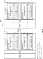
- FIG. 1A illustrates one embodiment of a system, such as a computing system 100A, of coupling a first simulator 115 and a second simulator 135 by a coupling framework 130 to simulate a coupled multi-physics model of a subsurface formation, where the first simulator 115 comprises a first physics model and the first simulator is in a process 120 and a memory space 125.
- the disclosed coupling framework 130 can be used to couple any two or more simulators comprising different physics models.
- the first simulator 115 and the second simulator 135 can comprise any combination of reservoir simulators, geo-mechanical simulators, chemical reaction simulators, and electromagnetic wave propagation simulators.
- FIG. 1A illustrates one embodiment of a system, such as a computing system 100A, of coupling a first simulator 115 and a second simulator 135 by a coupling framework 130 to simulate a coupled multi-physics model of a subsurface formation, where the first simulator 115 comprises a first physics model and the first simulator is in a process 120 and a memory space 125.
- the computing system 100A includes at least one processor 105 communicatively connected to at least one memory 110 via a data bus.
- the processor 105 may be any of a variety of types of programmable circuits capable of executing computer-readable instructions to perform various tasks, such as mathematical and communication (e.g., input/output) tasks. While processor 105 is depicted in FIG. 1A as a single central processing unit (CPU), the processor 105 can contain multiple CPUs (e.g., 2, 4, 6) each containing a single or multiple cores (e.g., 2, 4, 8, 10, 12, 16, 32, 64, etc.).
- the computing system 100A may comprise a computer, a phone, a tablet, a laptop, a wireless device, a wired device, a plurality of networked devices, etc. In some embodiments, the computing system 100A represents at least one computer. In some embodiments, the computing system 100A represents one computing node in a network cluster or in a cloud computing system.
- the memory 110 may include any of a variety of memory devices, such as using various types of computer-readable or computer storage media.
- a computer storage medium or computer-readable medium may be any medium that can contain or store the program for use by or in connection with the instruction execution system, apparatus, or device.
- the computer storage medium is embodied as a computer storage device, such as a memory.
- the computer-readable media and computer storage media of the present disclosure comprise at least some tangible devices, and in specific embodiments such computer-readable media and computer storage media include exclusively non-transitory media.
- the memory 110 may comprise dynamic random access memory (DRAM) or variants thereof.
- DRAM dynamic random access memory
- the memory utilized by the coupling framework for data exchange is DRAM or variants thereof.
- DRAM dynamic random access memory
- some of the disadvantages, such as slow data exchange via hard drives, of the traditional second approach may be avoided.
- Some embodiments may include other types of storage (not shown), such as mass storage devices, solid state memory, read-only memory (ROM), electrically-erasable programmable ROM, optical discs (e.g., CD-ROMs, DVDs, etc.), magnetic disks (e.g., hard disks, floppy disks, etc.), magnetic tapes, and other types of devices and/or articles of manufacture that store data.
- these other types of storage are in essence similar to "hard drives” and not utilized by the coupling framework for data exchange in FIGS. 1A-1B and 2A-2B .
- these other types of storage may include instructions (e.g., computer-executable instructions), programs, etc.
- the processer 105 loads the instructions, the programs, etc. and data from these other types of storage / "hard drives" to the memory 110.
- the memory 110 stores the first simulator 115 in the process 120 and the memory space 125.
- the first simulator 115 is stored in the process 120
- the process 120 is stored in the memory space 125 of the memory 110.
- the memory 110 also stores a coupling framework 130 of the first simulator 115.
- the memory 110 stores computer-executable instructions which, when executed, cause the processor 105 to perform loading, by the coupling framework 130 of the first simulator 115, the second simulator 135 as a library into the process 120 and the memory space 125 of the first simulator 115 to ensure that the first simulator 115 and the second simulator 135 share a common process (i.e. the process 120) and a common memory space (i.e., the memory space 125).
- the first simulator 115 comprises a first physics model and the second simulator 135 comprises a second physics model.
- the first simulator 115 or the second simulator 135 comprise a reservoir simulator. In one embodiment, the first simulator 115 or the second simulator 135 comprise a geo-mechanical simulator. In one embodiment, the first simulator 115 or the second simulator 135 comprise a chemical reaction simulator, such as reaction kinetics or equilibrium. In one embodiment, the first simulator 115 or the second simulator 135 comprise an electromagnetic wave propagation simulator. Any reservoir simulator, any geo-mechanical simulator, any chemical reaction simulator, or any electromagnetic wave propagation simulator may be utilized, such as those that are commercially available. For example, the reservoir simulator may be, but is not limited to, the Intersect TM (IX) reservoir simulator that is commercially available from the Schlumberger Technology Corporation.
- IX Intersect TM
- the geo-mechanical simulator may be, but is not limited to, the geo-mechanical simulator discussed in the following items (a) U.S. Patent No. 8,548,783 , (b) U.S. Patent No. 9,026,419 , (c) U.S. Patent No. 8,204,727 , (d) Zuluaga, E., Schmidt, J. H., & Dean, R. H. (2007, January 1).
- a first simulator e.g., a reservoir simulator
- a first simulator may even be coupled during the simulation with a different type of simulator(s) that is not listed herein.
- the memory 110 stores computer-executable instructions which, when executed, cause the processor 105 to perform simulating, by the first simulator 115 and the library corresponding to the second simulator 135 that are coupled by the coupling framework 130 during the simulating step, a coupled multi-physics model of the subsurface formation to generate a solution satisfying the first physics model of the first simulator 115, the second physics model of the second simulator 135, and interaction between the first physics model of the first simulator 115 and the second physics model of the second simulator 135.
- the coupled multi-physics model is comprised of the first physics model of the first simulator 115, the second physics model of the second simulator 135, and the interaction between the first physics model of the first simulator 115 and the second physics model of the second simulator 135.
- the coupling framework 130 performs the following during the simulating step to couple the first simulator 115 and the library corresponding to the second simulator 135:
- the coupling may change at different time steps of a particular simulation, such that one type of coupling (e.g., one-way coupling) may be utilized in some time steps of the particular simulation and at least one other type of coupling (e.g., two-way explicit coupling) may utilized in some other time steps of the particular simulation.
- one-way coupling may be utilized in some time steps of a particular simulation and two-way iterative coupling may be utilized in some other time steps of the particular simulation.
- two-way explicit coupling may be utilized in some time steps of a particular simulation and two-way iterative coupling may be utilized in some other time steps of the particular simulation.
- two-way explicit coupling may be utilized in some time steps of a particular simulation, two-way iterative coupling may be utilized in some other time steps of the particular simulation, and one-way coupling may be utilized in some other time steps of the particular simulation.
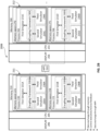
- FIG. 1B illustrates a completely parallel simulation.
- a system 200A comprises a plurality of nodes, such as a node 211 and a node 212. While FIG 1B only illustrates two nodes, one skilled in the art appreciates that additional computational nodes may be utilized. Each node includes a process in a respective memory space similar to FIG. 1A , and more specifically, a plurality of these are illustrated in each node of FIG. 1B .
- the computing system 200A includes at least one processor 205 (similar to the processor 105 of FIG. 1A ) communicatively connected to at least one memory 210 (similar to the memory 110 of FIG. 1A ) via a data bus.
- the memory 210 stores a first simulator 215 (similar to the first simulator 115 of FIG. 1A ) in a process 220 (similar to the process 120 of FIG. 1A ) and a memory space 225 (similar to the memory space 125 of FIG. 1A ).
- the first simulator 215A is stored in the process 220
- the process 220 is stored in the memory space 225 of the memory 210.
- the memory 210 also stores a coupling framework 230A (similar to the coupling framework 130 of FIG. 1A ) of the first simulator 215A.
- the memory 210 stores computer-executable instructions which, when executed, cause the processor 205 to perform loading, by the coupling framework 230A of the first simulator 215A, a second simulator 235A (similar to the second simulator 135 of FIG. 1A ) as a library into the process 220 and the memory space 225 of the first simulator 215A to ensure that the first simulator 215A and the second simulator 235A share a common process (i.e. the process 220) and a common memory space (i.e., the memory space 225).
- the first simulator 215A comprises a first physics model and the second simulator 235A comprises a second physics model.
- the memory 210 stores computer-executable instructions which, when executed, cause the processor 205 to perform simulating, by the first simulator 215A and the library corresponding to the second simulator 235A that are coupled by the coupling framework 230A during the simulating step, a coupled multi-physics model of the subsurface formation to generate a solution satisfying the first physics model of the first 215A, the second physics model of the second simulator 235A, and interaction between the first physics model of the first simulator 215A and the second physics model of the second simulator 235A.
- the coupled multi-physics model is comprised of the first physics model of the first simulator 215A, the second physics model of the second simulator 235A, and the interaction between the first physics model of the first simulator 215A and the second physics model of the second simulator 235A.
- the coupling framework 230A performs the following during the simulating step to couple the first simulator 215A and the library corresponding to the second simulator 235A: (i) controls data exchange between the first simulator 215A and the second simulator 235A through the common memory space (i.e., the memory space 225), and (ii) controls execution of the first simulator 215A and second simulator 235A responsive to the common process (i.e., process 120).
- the coupling framework 230A can receive feedback from the second simulator 235A and alter execution of the first simulator 215A responsive to the received feedback in the event of two-way coupling.
- the coupling framework 230A maps data between the first simulator 215A and the second simulator 235A in the event of grid misalignment.
- the coupling framework 230A maps the data in a globally conservative (e.g., mass, energy, etc.) manner between the first simulator 215 and the second simulator 235A in the event of grid misalignment.
- the coupling framework 230A can use at least one application program interface (API), such as an API defined by a developer, to control execution of the second simulator 235A.
- API application program interface
- altering execution of the first simulator 215A and mapping data between the first simulator 215A and second simulator 235A is not performed by the coupling framework 230A during each simulation (e.g., if no grid misalignment, then data does not need to be mapped).
- the computing system 200A also includes a process 221 and its associated configuration that is similar to the process 220 and its associated configuration.
- first simulator 215B is stored in the process 221
- the process 221 is stored in a memory space 226 of the memory 210.
- the memory 210 also stores a coupling framework 230B of the first simulator 215B.
- the memory 210 stores computer-executable instructions which, when executed, cause the processor 205 to perform the loading step by coupling framework 230B of the first simulator 215B, as well as perform simulating step, by the first simulator 215B and the library corresponding to a second simulator 235B that are coupled by the coupling framework 230B during the simulating step.
- the node 212 is similar to the node 211 of the computing system 200A.
- the node 212 comprises at least one processor 255 (similar to the processor 205) communicatively connected to at least one memory 260 (similar to the memory 210) via a data bus.
- the processor 255 of the node 212 may be the processor 205 of the node 211.
- the memory 260 of the node 212 may be the memory 210 of the node 211.
- the node 212 also includes a process 265 and its associated configuration that is similar to the process 220 and its associated configuration.
- a first simulator 215C is stored in the process 265, and the process 265 is stored in a memory space 270 of the memory 260.
- the memory 260 also stores a coupling framework 230C of the first simulator 215C.
- the memory 260 stores computer-executable instructions which, when executed, cause the processor 255 to perform the loading step by the coupling framework 230C of the first simulator 215C, as well as perform the simulating step, by the first simulator 215C and the library corresponding to a second simulator 235C that are coupled by the coupling framework 230C during the simulating step.
- the node 212 also includes a process 266 and its associated configuration that is similar to the process 265 and its associated configuration.
- a first simulator 215D is stored in the process 266, and the process 266 is stored in a memory space 271 of the memory 260.
- the memory 260 also stores a coupling framework 230D of the first simulator 215D.
- the memory 260 stores computer-executable instructions which, when executed, cause the processor 255 to perform the loading step by the coupling framework 230D of the first simulator 215D, as well as perform the simulating step, by the first simulator 215D and the library corresponding to a second simulator 23 5D that are coupled by the coupling framework 230D during the simulating step.
- the coupling framework 230 uses a message passing interface (MPI) 213 to: control data exchange between a plurality of processes such as the processes 220, 221, 265, 266; control data exchange between a plurality of nodes such as the nodes 211, 212; or any combination thereof.
- MPI message passing interface
- the coupling framework 230 establishes a communication pattern between a plurality of processes such as the processes 220, 221, 265, 266 and a plurality of nodes such as the nodes 211, 212 based on domain decomposition of the first physics model of the first simulator (such as the first simulator 215A) and domain decomposition of the second physics model of the second simulator (such as the second simulator 235A), where the domain decompositions are independent.
- the coupling framework 230 establishes a communication pattern between a plurality of processes such as the processes 220, 221, 265, 266 and a plurality of nodes such as the nodes 211, 212 based on domain decomposition of the first physics model of the first simulator (such as the first simulator 215A) and domain decomposition of the second physics model of the second simulator (such as the second simulator 235A), where the domain decompositions are dependent.
- each coupling framework 230 i.e., 230A, 230B, 230C, & 230D
- each of the coupling frameworks 230 may use the MPI 213 to: control data exchange between a plurality of processes such as the processes 220, 221, 265, 266; control data exchange between a plurality of nodes such as the nodes 211, 212; or any combination thereof.
- FIG. 2A is similar to FIG. 1A and FIG. 2B is similar to FIG. 1B except that a third simulator is illustrated in FIGS. 2A-2B .
- the coupled multi-physics model is simulated by system 100B in serial with the first simulator 115 and two or more simulators.
- the process 120 illustrates the first simulator 115 and two or more simulators such as the second simulator 135 and a third simulator 136.
- the coupled multi-physics model is simulated in parallel with a first simulator 115 and two or more simulators.
- the node 211 illustrates the first simulator 215A, the second simulator 235A, and a third simulator 236A in the process 220, as well as the first simulator 215B, the second simulator 235B, and a third simulator 236B in the process 221.
- the node 212 illustrates the first simulator 215C, the second simulator 235C, and a third simulator 236C in the process 265, as well as the first simulator 215D, the second simulator 235D, and a third simulator 236D in the process 266.
- a plurality of simulators such as the second simulator 235A and the third simulator 236A are loaded as libraries by the coupling framework 230A into the process 220 and the memory space 225 of the first simulator 215A to ensure that the first simulator 215A and the plurality of simulators 235A, 236A share the common process (i.e., the process 220) and the common memory space (i.e., the memory space 225).
- Each simulator of the plurality of simulators comprises a physics model.
- the first simulator 215A and the plurality of libraries corresponding to the plurality of simulators 235A, 236A are coupled by the coupling framework 230A during the simulating step and the coupled multi-physics model of the subsurface formation generates the solution satisfying the first physics model of the first simulator 215A, the physics models of the plurality of simulators 235A, 236A, and interaction between the first physics model of the first simulator 215A and the physics models of the plurality of simulators 235A, 236A.
- the coupled multi-physics model is comprised of the first physics model of the first simulator 215A, the physics models of the plurality of simulators 235A, 236A, and the interaction between the first physics model of the first simulator 215A and the physics models of the plurality of simulators 235A, 236A.
- the coupling framework 230A performs the following during the stimulating step to couple the first simulator 215A and the libraries corresponding to the plurality of simulators 235A, 236A: (i) controls data exchange between the first simulator 215A and the plurality of simulators 235A, 236A through the common memory space (i.e., the memory space 225), and (ii) controls execution of the first simulator 215A and the plurality of simulators 235A, 236A responsive to the common process (i.e., the process 220).
- the coupling framework 230A receives feedback from the plurality of simulators 235A, 236A and alters execution of the first simulator 215A responsive to the received feedback in the event of two-way coupling.
- the coupling framework 230A maps data between the first simulator 215A and the plurality of simulators 235A, 236A in the event of grid misalignment. In one embodiment, the coupling framework 230A maps the data in a globally conservative (e.g., mass, energy, etc.) manner between the first simulator 215A and the plurality of simulators 235A, 236A in the event of grid misalignment.
- a globally conservative e.g., mass, energy, etc.
- Each of the first simulator 215 i.e., 215A, 215B, 215C, & 215D
- the plurality of simulators 235, 236 i.e., 235A, 235B, 235C, 235D, 236A, 236B, 236C, 236D
- a reservoir simulator i.e., a geo-mechanical simulator, a chemical reaction simulators, an electromagnetic wave propagation simulator, or other physics-based simulator
- coupling a first simulator and a plurality of simulators of different types may improve the accuracy of the coupled multi-physics model of the subsurface formation and the simulation.
- the first simulator 215 can be a reservoir simulator and in one embodiment, the plurality of simulators comprises a geo-mechanical simulator and a chemical reaction simulator. In another embodiment, the plurality of simulators comprises a geo-mechanical simulator and an electromagnetic wave propagation simulator. In another embodiment, the plurality of simulators comprises a chemical reaction simulator and an electromagnetic wave propagation simulator. In another embodiment, the plurality of simulators comprises a geo-mechanical simulator, a chemical reaction simulator, and an electromagnetic wave propagation simulator.
- the plurality of simulators may be of the same type (e.g., all of the plurality of simulators are geo-mechanical simulators), but the first simulator is of a type that is different than the first simulator (e.g., the first simulator is not a geo-mechanical simulator and the first simulator is a reservoir simulator, a chemical reaction simulator, or an electromagnetic wave propagation simulator).
- the computing systems 100A, 100B, 200A, and 200B may also include displays 106, 206, 256, respectively, for presenting a visual output or a user interface associated with the simulation, such as presenting a visual output of the solution that is generated from the simulation (e.g., the solution satisfying the first physics model of the first simulator 115, the second physics model of the second simulator 135, and interaction between the first physics model of the first simulator 115 and the second physics model of the second simulator 135 for viewing by one or more users as in FIG. 1A ).
- the display 256 may be the same as the display 206 in the computing system 200 (i.e., 200A and 200B).
- the simulation may be initiated with a simulation application.
- the computing systems 100A, 100B, 200A, and 200B may include additional components, such as peripheral I/O devices, for example to allow a user to interact with user interfaces.
- peripheral I/O devices for example to allow a user to interact with user interfaces.
- the displays 106, 206, 256 and the peripheral I/O devices may allow a user to provide user input, view and/or manipulate visual output, or other functionality.
- Some embodiments may include an operating system (not shown) that includes procedures for handling various basic system services and for performing hardware dependent tasks.
- Some embodiments may include: a network communication module (not shown) that facilitates communication with other devices via a communication network interface(s) (wired or wireless) and one or more communication networks, such as the Internet, other wide area networks, local area networks, metropolitan area networks, and so on.
- Some embodiments may include a communication interface(s) (not shown) such that any of the data or processed data products may be transmitted via the communication interface(s) or the network interface and may be stored.
- other types of storage may include instructions (e.g., computer-executable instructions), programs, etc. for the method of coupling a first simulator and at least one simulator to simulate a coupled multi-physics model of a subsurface formation, and a processer (e.g., the processor 105) loads the instructions, the programs, etc. and data from these other types of storage / "hard drives" to the respective memory (e.g., the memory 110).
- Embodiments of the present disclosure can be implemented as a system (e.g., a computer, a computing system, etc.), a method (e.g., a process, a computer process or a computer implemented method, etc.), an article of manufacture (e.g., computer readable medium or computer storage medium), software, etc.
- a system e.g., a computer, a computing system, etc.
- a method e.g., a process, a computer process or a computer implemented method, etc.
- an article of manufacture e.g., computer readable medium or computer storage medium
- software etc.
- FIG. 3 this figure illustrates one embodiment of a method 300 of coupling a first simulator and a second simulator (or plurality of simulators) to simulate a coupled multi-physics model of a subsurface formation.
- the first simulator comprises a first physics model and the first simulator is in a process and a memory space.
- the discussion refers to reference numbers in FIGS. 1A-1B .
- the method 300 may be implemented via a simulation module with at least one sub-module, such as loading sub-module for 305, a simulating sub-module for 310, and a generating visual output sub-module for 315.
- One or more of these sub-modules may receive or retrieve data from a data sub-module, and one or more of these sub-modules may communicate with another sub-module.
- a data sub-module may receive or retrieve data from a data sub-module
- one or more of these sub-modules may communicate with another sub-module.
- various embodiments may be implemented in other ways.
- the method 300 comprises loading, by a coupling framework, the second simulator as a library into a process and a memory space with the first simulator to ensure that the first simulator and the second simulator share a common process and a common memory space.
- the second simulator comprises a second physics model.
- the library can be built using the first simulator extensibility header files.
- the coupling framework 130 of FIG. 1A serves as an abstract interface that allows the first simulator 115 to exchange data with an external simulator, such as the second simulator 135, through memory, such as the memory space 125.
- the external simulator may be compiled as a dynamic link library (or shared library for Linux) and the external simulator may be loaded at runtime as needed.
- the external simulator(s) may be built as a dynamic linking library (e.g., .dll files for Windows OS) or shared object library (e.g., .so files for Linux OS) with their modules wrapped using the coupling framework 130.
- the design allows for the coupling framework 130 to load an external library corresponding to an external simulator, or a plurality of external libraries corresponding to a plurality of external simulators, in a simulation run.
- This methodology also allows the first simulator 115 to be coupled with other 3rd party software libraries without exposing internal workings of the first simulator 115 to 3rd party developers and vice versa.
- the method 300 comprises simulating, by the coupling framework, the coupled multi-physics model of the subsurface formation to generate a solution satisfying the first physics model, the second physics model, and interaction between the first physics model and the second physics model.
- the coupled multi-physics model is comprised of the first physics model, the second physics model, and the interaction between the first physics model and the second physics model.
- the coupling framework performs the following during the stimulating step to couple the first simulator and the library corresponding to the second simulator: (i) controls data exchange between the first simulator and the second simulator through the common memory space, and (ii) controls execution of the first simulator and the second simulator responsive to the common process.
- the coupling framework maps the data in a globally conservative (e.g., mass, energy, etc.) manner between the first simulator and the second simulator in the event of grid misalignment.
- the coupling framework 130 controls data exchange between the first simulator 115 and the second simulator 135 through the common memory space (i.e., the memory space 125) by passing array pointers to the second simulator 135.
- the in-memory data exchange methodology incurs minimal computational overhead and makes it scalable for large scale parallel simulation.
- the coupling framework 130 can use at least one API to control execution of the external simulator, such as the second simulator 135.
- the coupling framework 130 includes coded logic and at least one API defined by a developer, and the library that is loaded adheres to the defined API(s).
- the external simulator implements the virtual methods in the coupling framework 130 that will be called by the first simulator 115 at different access points.
- the first simulator 115 serves as the controller for the coupled simulation and the coupling framework 130 of the first simulator 115 loads the dynamic linking or shared object library(ies) and calls specific functions defined by the coupling framework 130, which in turn cause the coupling framework 130 to exchange data with and execute corresponding modules in the external simulators.
- the coupling framework 130 as a part of the first simulator 115, loads external simulator library(ies), controls data exchange and calls external simulator(s) to execute particular modules.
- the coupling framework 130 also includes a globally conservative (e.g., mass, energy, etc.) mapping layer that interpolates and exchanges data through memory between the two simulators allowing the reservoir mesh to be non-aligned with the mesh of the external simulator, and the reservoir subdomain on each computational process to be non-aligned with the corresponding external simulator subdomain.
- a globally conservative mapping layer that interpolates and exchanges data through memory between the two simulators allowing the reservoir mesh to be non-aligned with the mesh of the external simulator, and the reservoir subdomain on each computational process to be non-aligned with the corresponding external simulator subdomain.
- the user will specify in the input file what external simulators to load, the input files for these external simulators, the coupling scheme (one-way, two-way explicit, two-way iterative), the mode for grid data mapping (aligned or nonaligned), and other parameters (e.g., period / convergence tolerance of coupling).
- the coupling scheme one-way, two-way explicit, two-way iterative
- the mode for grid data mapping aligned or nonaligned
- other parameters e.g., period / convergence tolerance of coupling.
- the same set of parallel computation processes may be utilized for both the first simulator and the external simulator(s) with the coupling framework 230 in FIG. 1B between them.
- Each computation process owns a subdomain of the first physics model and a subdomain of each external model. These different types of subdomains on each process do not need to overlap or use the same mesh and are depicted in Figures 1B and 2B with the notation A, B, C, and D.
- the subdomains of the first model do not need to be spatially contiguous.
- the subdomains of each external model do not need to be spatially contiguous.
- Data exchange between the subdomains of the first model and the subdomains of each external model is taken care of by the coupling framework 230 in memory and through the network to achieve scalable performance.
- Data exchange between the subdomains of the first model is optional and is taken care of by the first simulator when needed.
- Data exchange between the subdomains of each external model is optional and is taken care of by the corresponding external simulator when needed.
- the coupling framework 230 uses a message passing interface (MPI) 213 to: control data exchange between a plurality of processes such as the processes 220, 221, 265, 266; control data exchange between a plurality of nodes such as the nodes 211, 212; or any combination thereof.
- MPI message passing interface
- the coupling framework 230 establishes a communication pattern between a plurality of processes such as the processes 220, 221, 265, 266 and a plurality of nodes such as the nodes 211, 212 based on domain decomposition of the first physics model of the first simulator such as the first simulator 215A and domain decomposition of the second physics model of the second simulator such as the second simulator 235A, where the domain decompositions are independent.
- the coupling framework 230 establishes a communication pattern between a plurality of processes such as the processes 220, 221, 265, 266 and a plurality of nodes such as the nodes 211, 212 based on domain decomposition of the first physics model of the first simulator such as the first simulator 215A and domain decomposition of the second physics model of the second simulator such as the second simulator 235A, where the domain decompositions are dependent.
- MPI is utilized for data communication between different processes within a node or different processes within different nodes, and direct data exchange through memory within the process.
- the data exchange is hidden (in memory / MPI) behind the scene from the developer who develops the wrapper for the external simulator to be coupled to such that once set up is complete, it is very easy to use.
- the method 300 comprises generating a visual output that presents a solution satisfying the first physics model of the first simulator, the second physics model of the second simulator, and interaction between the first physics model of the first simulator and the second physics model of the second simulator (or solution satisfying the first physics model of the first simulator, the physics models of the plurality of simulators, and interaction between the first physics model of the first simulator and the physics models of the plurality of simulators) for viewing by one or more users.
- the solution may be presented or displayed via the display 106.
- Visual output of at least one physics model may be presented or displayed via the display 106 in some embodiments.
- a first simulator may be coupled with at least one other simulator using a coupling framework.
- the first simulator can be a reservoir simulator.
- the coupling framework allows both porosity and permeability coupling with a variety of coupling schemes.
- the coupling framework allows for iterative source term coupling.
- the coupling framework may also be utilized to efficiently model multi-physics problems through coupling with different external simulator(s), such as, but not limited to: (a) coupling a reservoir simulator and an external geo-mechanics simulator to understand flow and geo-mechanical deformation interaction; (b) coupling a reservoir simulator and a chemical reaction simulator to include reaction kinetics in reservoir flow simulation to improve forecast accuracy, and/or (c) coupling a reservoir simulator and an electromagnetic wave propagation simulator to model radio frequency heating to optimize production.
- a reservoir simulator may even be coupled with a geo-mechanics simulator, an electromagnetic wave propagation simulator, and a chemical reaction simulator (e.g., reaction kinetics) simultaneously.
- the interpolation between the flow and geomechanics subdomains may be bulk volume or pore volume weighted, depending on the nature of the property to be mapped.
- the properties for the matrix and the fracture system may be mapped separately.
- FIG. 4 illustrates an embodiment where the above coupling framework is applied between a reservoir simulator and a geomechanics simulator.
- Process 400 shows example steps as the coupling framework is utilized.
- a grid mapping module sets up a communication pattern and mapping coefficients between the reservoir simulator and the geomechanical simulator. Domain decomposition of reservoir and geomechanical simulator grids can be performed independently in respective simulators. Partitioned geomechanical simulator domains can be exchanged to allow for better overlapping with reservoir simulator domains.
- the communication pattern is fixed and all subsequent MPI communications are handled by the grid mapping module behind the scene. The user can define the mode for grid data mapping (aligned or nonaligned).
- the geomechanical grid occupying corresponding region(s) is compared to the reservoir simulator grid.
- a binary search tree e.g., k-d tree
- Each geomechanical domain may or may not contain reservoir simulation grid cells.
- each reservoir domain may or may not contain geomechanics grid cells.
- the resulting array containing mapped geomechanical grid cells can be used as the mapping coefficient.
- mapped properties can be calculated as weighted sums of source properties.
- reservoir simulation cells corresponding to geomechanical cells can be quickly filtered using a k-d tree.
- Each pair of nearby cells can be tested to see whether they intersect, e.g., using Boolean Gilbert-Johnson-Keerthi (BGJK) algorithm, and an intersection polyhedral can be created for each pair of intersecting cells.
- the (bulk) volume of each intersection polyhedral can then be calculated and normalized as the mapping coefficient. Examples of aligned and nonaligned grids are illustrated in Figures 5A and 5B , respectively.
- the reservoir simulator is initialized.
- the reservoir simulator passes array pointers for mapped properties and overlapped geomechanical grid cells to the geomechanical simulator. This can be done through an API.
- the user can also define the coupling scheme (one-way, two-way explicit, two-way iterative), and other parameters (e.g., period / convergence tolerance of coupling) in the input files for these external simulators.
- the geomechanical simulator is initialized.
- reservoir simulation data e.g., pore volume compressibilities, permeability multiplier
- step 420 the reservoir simulator performs nonlinear iteration such that the reservoir simulator maps data into the geomechanical arrays and communicates with the geomechanical simulator via API (iterative coupling).
- the geomechanical simulator can solve geomechanics equations, report convergence flag, and updates reservoir simulation data ( ⁇ , pore volume compressibilities, permeability multiplier), which are then mapped back to reservoir simulator arrays via the API in step 425.
- the reservoir simulator and geomechanical simulator continue iterations in step 420 and step 425 until convergence is reached in step 430.
- a final solve is then performed in step 435, and at the end of the timestep, the reservoir simulator maps data into geomechanical arrays and communicates to the geomechanical simulator to solve geomechanics equations via the API (one-way or explicit coupling).
- the geomechanical simulator then updates and maps reservoir simulation data ( ⁇ , pore volume compressibilities, permeability multiplier) back to reservoir simulator arrays via the API (explicit coupling).
- the reservoir and geomechanical simulators can save results or cut timesteps.
- the geomechanical simulator reads time-dependent data and outputs results if scheduled.
- the reservoir simulator reads time-dependent data and outputs results if scheduled.
- the framework proceeds to the next time step and this is repeated until the end of coupled simulation based on the process schedule.
- Process 400 achieves good parallel scalability (data exchanged in memory or via MPI) and excellent efficiency/accuracy in mapping and exchanging data. Further, it is minimally intrusive as the simulators can be kept separate and the geomechanical simulator can be loaded at run time. It allows for versatile coupling schemes by controlling the direction and frequency of the data exchange and convergence criteria (one-way, two-way explicit and iterative) and flexible with grid mapping (aligned/nonaligned, independent domain sizes and decomposition). While applied to a reservoir and geomechanics simulator in this example, the coupling framework also enables multi-physics coupling with other external software libraries (e.g., reaction kinetics, electromagnetic solvers, etc.).
- other external software libraries e.g., reaction kinetics, electromagnetic solvers, etc.
- the invention also provides a computer program or a computer program product for carrying out any of the methods (cf. computer-implemented methods) described herein, and a computer readable medium having stored thereon a program for carrying out any of the methods described herein.
- a computer program embodying the invention may be stored on a computer-readable medium, or it could, for example, be in the form of a signal such as a downloadable data signal provided from an Internet website, or it could be in any other form.
Landscapes
- Engineering & Computer Science (AREA)
- Physics & Mathematics (AREA)
- General Physics & Mathematics (AREA)
- Life Sciences & Earth Sciences (AREA)
- General Life Sciences & Earth Sciences (AREA)
- Geology (AREA)
- Theoretical Computer Science (AREA)
- Environmental & Geological Engineering (AREA)
- Business, Economics & Management (AREA)
- Educational Administration (AREA)
- Educational Technology (AREA)
- Pure & Applied Mathematics (AREA)
- Algebra (AREA)
- Computational Mathematics (AREA)
- Mathematical Analysis (AREA)
- Mathematical Optimization (AREA)
- Mathematical Physics (AREA)
- Remote Sensing (AREA)
- Geophysics (AREA)
- Geochemistry & Mineralogy (AREA)
- Mining & Mineral Resources (AREA)
- Acoustics & Sound (AREA)
- Paleontology (AREA)
- Fluid Mechanics (AREA)
- Management, Administration, Business Operations System, And Electronic Commerce (AREA)
- Software Systems (AREA)
- General Engineering & Computer Science (AREA)
Claims (14)
- Verfahren (300) zum Koppeln eines ersten Simulators und eines zweiten Simulators, um ein gekoppeltes Mehrfachphysikmodell einer unterirdischen Formation zu simulieren, wobei der erste Simulator ein erstes Physikmodell umfasst und der zweite Simulator ein zweites Physikmodell umfasst, wobei das Verfahren Folgendes umfasst:Laden (305) des zweiten Simulators durch einen Kopplungsrahmen als eine geteilte Bibliothek in einen gemeinsamen Prozess und einen gemeinsamen Speicherraum mit dem ersten Simulator, um das gekoppelte Mehrfachphysikmodell der unterirdischen Formation zu erzeugen; undSimulieren (310) des gekoppelten Mehrfachphysikmodells der unterirdischen Formation durch den Kopplungsrahmen dergestalt, dass der Kopplungsrahmen Folgendes während der Simulation durchführt, um den ersten Simulator und die dem zweiten Simulator entsprechende geteilte Bibliothek zu simulieren:Steuern des Datenaustauschs zwischen dem ersten Simulator und dem zweiten Simulator mittels des gemeinsamen Speicherraums; undSteuern der Ausführung des ersten Simulators und des zweiten Simulators als Reaktion auf den gemeinsamen Prozess,wobei der Kopplungsrahmen im Fall von Gitterfehlausrichtung Daten zwischen dem ersten Simulator und dem zweiten Simulator abbildet.
- Verfahren nach Anspruch 1, wobei der Kopplungsrahmen Einweg-Kopplung, explizite Zweiwege-Kopplung, iterative Zweiwege-Kopplung oder eine beliebige Kombination davon erlaubt.
- Verfahren nach Anspruch 2, wobei der Kopplungsrahmen Ausführung des ersten Simulators als Reaktion auf Rückmeldung von dem zweiten Simulator in der expliziten Zweiwege-Kopplung, der iterativen Zweiwege-Kopplung oder einer beliebigen Kombination davon ändert.
- Verfahren nach Anspruch 1, wobei der Kopplungsrahmen die Daten auf eine global konservative Weise abbildet.
- Verfahren nach einem der Ansprüche 1-4, wobei der Kopplungsrahmen mindestens eine API (Anwendungsprogrammschnittstelle) zur Steuerung der Ausführung des ersten Simulators, des zweiten Simulators oder sowohl des ersten Simulators als auch des zweiten Simulators als Reaktion auf den gemeinsamen Prozess verwendet.
- Verfahren nach einem der Ansprüche 1-5, wobei der Kopplungsrahmen den zweiten Simulator als die geteilte Bibliothek in mehrere gemeinsame Prozesse und mehrere gemeinsame Speicherräume mit dem ersten Simulator lädt, um das gekoppelte Mehrfachphysikmodell der unterirdischen Formation zu erzeugen.
- Verfahren nach einem der Ansprüche 1-5, wobei mehrere Simulatoren, die jeweils ein Physikmodell umfassen, als mehrere geteilte Bibliotheken durch den Kopplungsrahmen in den gemeinsamen Prozess und den gemeinsamen Speicherraum mit dem ersten Simulator geladen werden; und
der Kopplungsrahmen Folgendes während des Simulierens zur Kopplung des ersten Simulators und der den mehreren Simulatoren entsprechenden mehreren geteilten Bibliotheken durchführt:(i) Steuern des Datenaustauschs zwischen dem ersten Simulator und den mehreren Simulatoren mittels des gemeinsamen Speicherraums; und(ii) Steuern der Ausführung des ersten Simulators und der mehreren Simulatoren als Reaktion auf den gemeinsamen Prozess. - Verfahren nach Anspruch 7, wobei der Kopplungsrahmen die mehreren Simulatoren als die mehreren geteilten Bibliotheken in mehrere gemeinsame Prozesse und mehrere gemeinsame Speicherräume mit dem ersten Simulator lädt, um das gekoppelte Mehrfachphysikmodell der unterirdischen Formation zu erzeugen.
- Verfahren nach Anspruch 6 oder 8, wobeider Kopplungsrahmen ein Kommunikationsmuster zwischen den mehreren gemeinsamen Prozessen und den mehreren gemeinsamen Speicherräumen auf der Basis von Domänenzerlegungen herstellt; und/oderder Kopplungsrahmen Einweg-Kopplung, explizite Zweiwege-Kopplung, iterative Zweiwege-Kopplung oder eine beliebige Kombination davon für jeden der mehreren gemeinsamen Prozesse herstellt; und/oderdie mehreren gemeinsamen Prozesse und die mehreren gemeinsamen Speicherräume in mehreren Knoten residieren.
- Verfahren nach Anspruch 6, 8 oder 9, wobei der Kopplungsrahmen eine MPI (Nachrichtenweitergabeschnittstelle) verwendet zumSteuern des Datenaustauschs zwischen den mehreren gemeinsamen Prozessen;Steuern des Datenaustauschs zwischen den mehreren Knoten; odereine beliebige Kombination davon.
- Verfahren nach einem der Ansprüche 1-10, wobei jeder Simulator einen Reservoirsimulator, einen geomechanischen Simulator, einen Chemische-Reaktion-Simulator oder einen Elektromagnetische-Welle-Ausbreitungssimulator umfasst.
- System (100A; 200A; 100B; 200B) zur Kopplung eines ersten Simulators und eines zweiten Simulators, um ein gekoppeltes Mehrfachphysikmodell einer unterirdischen Formation zu simulieren, wobei der erste Simulator ein erstes Physikmodell umfasst und der zweite Simulator ein zweites Physikmodell umfasst, wobei das System Folgendes umfasst:einen Prozessor (105; 205; 255); undeinen kommunikativ mit dem Prozessor (105; 205; 255) gekoppelten Speicher (110; 210; 260), wobei der Speicher (110; 210; 260) computerausführbare Anweisungen speichert, die, wenn sie durch den Prozessor (105; 205; 255) ausgeführt werden, bewirken, dass der Prozessor (105; 205; 255) das Verfahren nach einem der vorhergehenden Ansprüche ausführt.
- Computerprogramm, das, wenn es durch einen Computer (100A; 200A; 100B; 200B) ausgeführt wird, bewirkt, dass der Computer (100A; 200A; 100B; 200B) das Verfahren nach einem der Ansprüche 1 bis 11 ausführt.
- Computerlesbares Medium, auf dem das Computerprogramm nach Anspruch 13 gespeichert ist.
Applications Claiming Priority (1)
| Application Number | Priority Date | Filing Date | Title |
|---|---|---|---|
| US201962817337P | 2019-03-12 | 2019-03-12 |
Publications (2)
| Publication Number | Publication Date |
|---|---|
| EP3708768A1 EP3708768A1 (de) | 2020-09-16 |
| EP3708768B1 true EP3708768B1 (de) | 2023-07-12 |
Family
ID=69804776
Family Applications (1)
| Application Number | Title | Priority Date | Filing Date |
|---|---|---|---|
| EP20162597.7A Active EP3708768B1 (de) | 2019-03-12 | 2020-03-12 | Kopplung eines simulators und mindestens eines weiteren simulators |
Country Status (3)
| Country | Link |
|---|---|
| US (1) | US12181623B2 (de) |
| EP (1) | EP3708768B1 (de) |
| CA (1) | CA3075373A1 (de) |
Families Citing this family (2)
| Publication number | Priority date | Publication date | Assignee | Title |
|---|---|---|---|---|
| WO2022271591A1 (en) * | 2021-06-21 | 2022-12-29 | Schlumberger Technology Corporation | Automated decision-making and learning techniques with heterogeneous simulators in coiled tubing operations |
| WO2023209421A1 (en) * | 2022-04-27 | 2023-11-02 | Zare Manizani Mohammad | Sediment analysis software along with scanning electron microscope toolbox for image processing |
Family Cites Families (13)
| Publication number | Priority date | Publication date | Assignee | Title |
|---|---|---|---|---|
| US7761270B2 (en) | 2000-12-29 | 2010-07-20 | Exxonmobil Upstream Research Co. | Computer system and method having a facility management logic architecture |
| US7277836B2 (en) | 2000-12-29 | 2007-10-02 | Exxonmobil Upstream Research Company | Computer system and method having a facility network architecture |
| EA008321B1 (ru) | 2002-11-23 | 2007-04-27 | Шлумбергер Текнолоджи Корпорейшн | Способ и устройство для объединённых моделирований пластов-коллекторов и поверхностных сетей трубопроводов производственного оборудования |
| CN101443767B (zh) | 2004-11-29 | 2013-09-04 | 切夫里昂美国公司 | 使用基于动态组成的可扩展面向对象体系结构仿真物理系统中的流体流动的方法、系统和程序存储设备 |
| US7707018B2 (en) | 2004-12-14 | 2010-04-27 | Schlumberger Technology Corporation | Finite volume method system and program storage device for linear elasticity involving coupled stress and flow in a reservoir simulator |
| US20080168092A1 (en) * | 2007-01-10 | 2008-07-10 | General Electric Company | Systems and methods for turbine control simulation |
| CA2738122C (en) | 2008-09-19 | 2020-02-11 | Chevron U.S.A. Inc. | Computer-implemented systems and methods for use in modeling a geomechanical reservoir system |
| US8280709B2 (en) | 2008-10-03 | 2012-10-02 | Schlumberger Technology Corporation | Fully coupled simulation for fluid flow and geomechanical properties in oilfield simulation operations |
| US8548783B2 (en) | 2009-09-17 | 2013-10-01 | Chevron U.S.A. Inc. | Computer-implemented systems and methods for controlling sand production in a geomechanical reservoir system |
| CA2783787A1 (en) | 2010-02-12 | 2011-08-18 | Exxonmobil Upstream Research Company | Method and system for creating history-matched simulation models |
| GB2503578A (en) | 2010-12-13 | 2014-01-01 | Chevron Usa | Method and system for coupling reservoir and surface facility simulations |
| US10372847B2 (en) * | 2016-07-01 | 2019-08-06 | General Electric Company | Systems and methods to integrate power production simulation with power distribution simulation |
| US11506047B2 (en) * | 2018-12-17 | 2022-11-22 | Saudi Arabian Oil Company | Image based inspection and automated inventory and supply chain management of well equipment |
-
2020
- 2020-03-12 US US16/816,333 patent/US12181623B2/en active Active
- 2020-03-12 EP EP20162597.7A patent/EP3708768B1/de active Active
- 2020-03-12 CA CA3075373A patent/CA3075373A1/en active Pending
Also Published As
| Publication number | Publication date |
|---|---|
| EP3708768A1 (de) | 2020-09-16 |
| US12181623B2 (en) | 2024-12-31 |
| US20200294413A1 (en) | 2020-09-17 |
| CA3075373A1 (en) | 2020-09-12 |
Similar Documents
| Publication | Publication Date | Title |
|---|---|---|
| US9910938B2 (en) | Shale gas production forecasting | |
| US9390204B2 (en) | Multisegment fractures | |
| CA2920884C (en) | Formation stability modeling | |
| CA2838190C (en) | Multisegment fractures | |
| WO2016037168A1 (en) | Well survivability in multidimensional geomechanical space | |
| EP4136322B1 (de) | Kompositreservoirsimulation | |
| WO2009139949A1 (en) | Modeling of hydrocarbon reservoirs using design of experiments methods | |
| NO346116B1 (en) | Multiphase flow in a wellbore and associated hydraulic fracturing | |
| CA3012429C (en) | Hybrid 3d geocellular representation of selected natural fracture network subsets | |
| US20240411954A1 (en) | Reservoir simulator | |
| CA3268219A1 (en) | CARBON CAPTURE AND STORAGE OPERATIONS AND WORKFLOWS THROUGH UNDERGROUND STRUCTURE SIMULATION | |
| US12181623B2 (en) | Coupling a simulator and at least one other simulator | |
| CA2818464C (en) | Shale gas production forecasting | |
| Al-Hamad et al. | Drilling with 3D geomechanical modeling-efficient simulation method | |
| Xiao et al. | Multi‐Scale Geomechanical Modelling of Unconventional Shale Gas: The Implication on Assisting Geophysics–Geology–Engineering Integration | |
| Janjua et al. | Development of heavy oil recovery technique using toe-To-heel cyclic steam stimulation method for heterogeneous reservoirs | |
| Han et al. | In-situ and induced stresses in the development of unconventional resources | |
| Liu et al. | Coupling EDFM-AI and ESMDA for Dynamic Unconventional Reservoir Characterizations | |
| Al-Shemali et al. | Subsurface Digital Models for Automated Drilling Risk Prediction in West Kuwait Jurassic Oilfields | |
| Torres et al. | Geomechanics Aspects of the Oriente Basin, Ecuador, South America | |
| Pavlov et al. | 4D Geomechnical Model Creation for Estimation of Field Development Effect on Hydraulic Fracture Geometry | |
| Kuleshov et al. | Optimization of the Verkhnechonskoye Field Development Process by Mapping Geomechanical Properties and Stresses | |
| Pavlyukov et al. | An integrated approach for planning of multistage hydraulic fracturing in low-permeability gas-saturated reservoirs with natural fractures | |
| Zhou et al. | Fully Coupled Multi-Scale Geomechanical Modeling for Hydraulic Fracture Optimization and EOR Improvement | |
| Carrero et al. | Coupled Compositional/Geomechanics Reservoir Simulation of Eocene C-Sup VLG3676, Block VII Ceuta Field, Venezuela: A Case Study |
Legal Events
| Date | Code | Title | Description |
|---|---|---|---|
| PUAI | Public reference made under article 153(3) epc to a published international application that has entered the european phase |
Free format text: ORIGINAL CODE: 0009012 |
|
| STAA | Information on the status of an ep patent application or granted ep patent |
Free format text: STATUS: THE APPLICATION HAS BEEN PUBLISHED |
|
| AK | Designated contracting states |
Kind code of ref document: A1 Designated state(s): AL AT BE BG CH CY CZ DE DK EE ES FI FR GB GR HR HU IE IS IT LI LT LU LV MC MK MT NL NO PL PT RO RS SE SI SK SM TR |
|
| AX | Request for extension of the european patent |
Extension state: BA ME |
|
| STAA | Information on the status of an ep patent application or granted ep patent |
Free format text: STATUS: REQUEST FOR EXAMINATION WAS MADE |
|
| 17P | Request for examination filed |
Effective date: 20210316 |
|
| RBV | Designated contracting states (corrected) |
Designated state(s): AL AT BE BG CH CY CZ DE DK EE ES FI FR GB GR HR HU IE IS IT LI LT LU LV MC MK MT NL NO PL PT RO RS SE SI SK SM TR |
|
| GRAP | Despatch of communication of intention to grant a patent |
Free format text: ORIGINAL CODE: EPIDOSNIGR1 |
|
| STAA | Information on the status of an ep patent application or granted ep patent |
Free format text: STATUS: GRANT OF PATENT IS INTENDED |
|
| INTG | Intention to grant announced |
Effective date: 20230130 |
|
| GRAS | Grant fee paid |
Free format text: ORIGINAL CODE: EPIDOSNIGR3 |
|
| GRAA | (expected) grant |
Free format text: ORIGINAL CODE: 0009210 |
|
| STAA | Information on the status of an ep patent application or granted ep patent |
Free format text: STATUS: THE PATENT HAS BEEN GRANTED |
|
| P01 | Opt-out of the competence of the unified patent court (upc) registered |
Effective date: 20230522 |
|
| AK | Designated contracting states |
Kind code of ref document: B1 Designated state(s): AL AT BE BG CH CY CZ DE DK EE ES FI FR GB GR HR HU IE IS IT LI LT LU LV MC MK MT NL NO PL PT RO RS SE SI SK SM TR |
|
| REG | Reference to a national code |
Ref country code: CH Ref legal event code: EP |
|
| REG | Reference to a national code |
Ref country code: DE Ref legal event code: R096 Ref document number: 602020013497 Country of ref document: DE |
|
| REG | Reference to a national code |
Ref country code: IE Ref legal event code: FG4D |
|
| REG | Reference to a national code |
Ref country code: NL Ref legal event code: FP |
|
| REG | Reference to a national code |
Ref country code: NO Ref legal event code: T2 Effective date: 20230712 |
|
| REG | Reference to a national code |
Ref country code: LT Ref legal event code: MG9D |
|
| REG | Reference to a national code |
Ref country code: AT Ref legal event code: MK05 Ref document number: 1587365 Country of ref document: AT Kind code of ref document: T Effective date: 20230712 |
|
| PG25 | Lapsed in a contracting state [announced via postgrant information from national office to epo] |
Ref country code: GR Free format text: LAPSE BECAUSE OF FAILURE TO SUBMIT A TRANSLATION OF THE DESCRIPTION OR TO PAY THE FEE WITHIN THE PRESCRIBED TIME-LIMIT Effective date: 20231013 |
|
| PG25 | Lapsed in a contracting state [announced via postgrant information from national office to epo] |
Ref country code: ES Free format text: LAPSE BECAUSE OF FAILURE TO SUBMIT A TRANSLATION OF THE DESCRIPTION OR TO PAY THE FEE WITHIN THE PRESCRIBED TIME-LIMIT Effective date: 20230712 |
|
| PG25 | Lapsed in a contracting state [announced via postgrant information from national office to epo] |
Ref country code: IS Free format text: LAPSE BECAUSE OF FAILURE TO SUBMIT A TRANSLATION OF THE DESCRIPTION OR TO PAY THE FEE WITHIN THE PRESCRIBED TIME-LIMIT Effective date: 20231112 |
|
| PG25 | Lapsed in a contracting state [announced via postgrant information from national office to epo] |
Ref country code: SE Free format text: LAPSE BECAUSE OF FAILURE TO SUBMIT A TRANSLATION OF THE DESCRIPTION OR TO PAY THE FEE WITHIN THE PRESCRIBED TIME-LIMIT Effective date: 20230712 Ref country code: RS Free format text: LAPSE BECAUSE OF FAILURE TO SUBMIT A TRANSLATION OF THE DESCRIPTION OR TO PAY THE FEE WITHIN THE PRESCRIBED TIME-LIMIT Effective date: 20230712 Ref country code: PT Free format text: LAPSE BECAUSE OF FAILURE TO SUBMIT A TRANSLATION OF THE DESCRIPTION OR TO PAY THE FEE WITHIN THE PRESCRIBED TIME-LIMIT Effective date: 20231113 Ref country code: LV Free format text: LAPSE BECAUSE OF FAILURE TO SUBMIT A TRANSLATION OF THE DESCRIPTION OR TO PAY THE FEE WITHIN THE PRESCRIBED TIME-LIMIT Effective date: 20230712 Ref country code: LT Free format text: LAPSE BECAUSE OF FAILURE TO SUBMIT A TRANSLATION OF THE DESCRIPTION OR TO PAY THE FEE WITHIN THE PRESCRIBED TIME-LIMIT Effective date: 20230712 Ref country code: IS Free format text: LAPSE BECAUSE OF FAILURE TO SUBMIT A TRANSLATION OF THE DESCRIPTION OR TO PAY THE FEE WITHIN THE PRESCRIBED TIME-LIMIT Effective date: 20231112 Ref country code: HR Free format text: LAPSE BECAUSE OF FAILURE TO SUBMIT A TRANSLATION OF THE DESCRIPTION OR TO PAY THE FEE WITHIN THE PRESCRIBED TIME-LIMIT Effective date: 20230712 Ref country code: GR Free format text: LAPSE BECAUSE OF FAILURE TO SUBMIT A TRANSLATION OF THE DESCRIPTION OR TO PAY THE FEE WITHIN THE PRESCRIBED TIME-LIMIT Effective date: 20231013 Ref country code: FI Free format text: LAPSE BECAUSE OF FAILURE TO SUBMIT A TRANSLATION OF THE DESCRIPTION OR TO PAY THE FEE WITHIN THE PRESCRIBED TIME-LIMIT Effective date: 20230712 Ref country code: ES Free format text: LAPSE BECAUSE OF FAILURE TO SUBMIT A TRANSLATION OF THE DESCRIPTION OR TO PAY THE FEE WITHIN THE PRESCRIBED TIME-LIMIT Effective date: 20230712 Ref country code: AT Free format text: LAPSE BECAUSE OF FAILURE TO SUBMIT A TRANSLATION OF THE DESCRIPTION OR TO PAY THE FEE WITHIN THE PRESCRIBED TIME-LIMIT Effective date: 20230712 |
|
| PG25 | Lapsed in a contracting state [announced via postgrant information from national office to epo] |
Ref country code: PL Free format text: LAPSE BECAUSE OF FAILURE TO SUBMIT A TRANSLATION OF THE DESCRIPTION OR TO PAY THE FEE WITHIN THE PRESCRIBED TIME-LIMIT Effective date: 20230712 |
|
| REG | Reference to a national code |
Ref country code: DE Ref legal event code: R097 Ref document number: 602020013497 Country of ref document: DE |
|
| PG25 | Lapsed in a contracting state [announced via postgrant information from national office to epo] |
Ref country code: SM Free format text: LAPSE BECAUSE OF FAILURE TO SUBMIT A TRANSLATION OF THE DESCRIPTION OR TO PAY THE FEE WITHIN THE PRESCRIBED TIME-LIMIT Effective date: 20230712 Ref country code: RO Free format text: LAPSE BECAUSE OF FAILURE TO SUBMIT A TRANSLATION OF THE DESCRIPTION OR TO PAY THE FEE WITHIN THE PRESCRIBED TIME-LIMIT Effective date: 20230712 Ref country code: EE Free format text: LAPSE BECAUSE OF FAILURE TO SUBMIT A TRANSLATION OF THE DESCRIPTION OR TO PAY THE FEE WITHIN THE PRESCRIBED TIME-LIMIT Effective date: 20230712 Ref country code: DK Free format text: LAPSE BECAUSE OF FAILURE TO SUBMIT A TRANSLATION OF THE DESCRIPTION OR TO PAY THE FEE WITHIN THE PRESCRIBED TIME-LIMIT Effective date: 20230712 Ref country code: CZ Free format text: LAPSE BECAUSE OF FAILURE TO SUBMIT A TRANSLATION OF THE DESCRIPTION OR TO PAY THE FEE WITHIN THE PRESCRIBED TIME-LIMIT Effective date: 20230712 Ref country code: SK Free format text: LAPSE BECAUSE OF FAILURE TO SUBMIT A TRANSLATION OF THE DESCRIPTION OR TO PAY THE FEE WITHIN THE PRESCRIBED TIME-LIMIT Effective date: 20230712 |
|
| PLBE | No opposition filed within time limit |
Free format text: ORIGINAL CODE: 0009261 |
|
| STAA | Information on the status of an ep patent application or granted ep patent |
Free format text: STATUS: NO OPPOSITION FILED WITHIN TIME LIMIT |
|
| PG25 | Lapsed in a contracting state [announced via postgrant information from national office to epo] |
Ref country code: IT Free format text: LAPSE BECAUSE OF FAILURE TO SUBMIT A TRANSLATION OF THE DESCRIPTION OR TO PAY THE FEE WITHIN THE PRESCRIBED TIME-LIMIT Effective date: 20230712 |
|
| 26N | No opposition filed |
Effective date: 20240415 |
|
| PG25 | Lapsed in a contracting state [announced via postgrant information from national office to epo] |
Ref country code: SI Free format text: LAPSE BECAUSE OF FAILURE TO SUBMIT A TRANSLATION OF THE DESCRIPTION OR TO PAY THE FEE WITHIN THE PRESCRIBED TIME-LIMIT Effective date: 20230712 |
|
| REG | Reference to a national code |
Ref country code: DE Ref legal event code: R119 Ref document number: 602020013497 Country of ref document: DE |
|
| REG | Reference to a national code |
Ref country code: CH Ref legal event code: PL |
|
| PG25 | Lapsed in a contracting state [announced via postgrant information from national office to epo] |
Ref country code: BG Free format text: LAPSE BECAUSE OF FAILURE TO SUBMIT A TRANSLATION OF THE DESCRIPTION OR TO PAY THE FEE WITHIN THE PRESCRIBED TIME-LIMIT Effective date: 20230712 |
|
| PG25 | Lapsed in a contracting state [announced via postgrant information from national office to epo] |
Ref country code: LU Free format text: LAPSE BECAUSE OF NON-PAYMENT OF DUE FEES Effective date: 20240312 |
|
| PG25 | Lapsed in a contracting state [announced via postgrant information from national office to epo] |
Ref country code: MC Free format text: LAPSE BECAUSE OF FAILURE TO SUBMIT A TRANSLATION OF THE DESCRIPTION OR TO PAY THE FEE WITHIN THE PRESCRIBED TIME-LIMIT Effective date: 20230712 |
|
| PG25 | Lapsed in a contracting state [announced via postgrant information from national office to epo] |
Ref country code: MC Free format text: LAPSE BECAUSE OF FAILURE TO SUBMIT A TRANSLATION OF THE DESCRIPTION OR TO PAY THE FEE WITHIN THE PRESCRIBED TIME-LIMIT Effective date: 20230712 Ref country code: LU Free format text: LAPSE BECAUSE OF NON-PAYMENT OF DUE FEES Effective date: 20240312 Ref country code: BG Free format text: LAPSE BECAUSE OF FAILURE TO SUBMIT A TRANSLATION OF THE DESCRIPTION OR TO PAY THE FEE WITHIN THE PRESCRIBED TIME-LIMIT Effective date: 20230712 |
|
| REG | Reference to a national code |
Ref country code: BE Ref legal event code: MM Effective date: 20240331 |
|
| PG25 | Lapsed in a contracting state [announced via postgrant information from national office to epo] |
Ref country code: DE Free format text: LAPSE BECAUSE OF NON-PAYMENT OF DUE FEES Effective date: 20241001 |
|
| PG25 | Lapsed in a contracting state [announced via postgrant information from national office to epo] |
Ref country code: BE Free format text: LAPSE BECAUSE OF NON-PAYMENT OF DUE FEES Effective date: 20240331 |
|
| PG25 | Lapsed in a contracting state [announced via postgrant information from national office to epo] |
Ref country code: IE Free format text: LAPSE BECAUSE OF NON-PAYMENT OF DUE FEES Effective date: 20240312 |
|
| PG25 | Lapsed in a contracting state [announced via postgrant information from national office to epo] |
Ref country code: IE Free format text: LAPSE BECAUSE OF NON-PAYMENT OF DUE FEES Effective date: 20240312 Ref country code: DE Free format text: LAPSE BECAUSE OF NON-PAYMENT OF DUE FEES Effective date: 20241001 Ref country code: BE Free format text: LAPSE BECAUSE OF NON-PAYMENT OF DUE FEES Effective date: 20240331 Ref country code: CH Free format text: LAPSE BECAUSE OF NON-PAYMENT OF DUE FEES Effective date: 20240331 |
|
| PG25 | Lapsed in a contracting state [announced via postgrant information from national office to epo] |
Ref country code: CY Free format text: LAPSE BECAUSE OF FAILURE TO SUBMIT A TRANSLATION OF THE DESCRIPTION OR TO PAY THE FEE WITHIN THE PRESCRIBED TIME-LIMIT; INVALID AB INITIO Effective date: 20200312 |
|
| PG25 | Lapsed in a contracting state [announced via postgrant information from national office to epo] |
Ref country code: HU Free format text: LAPSE BECAUSE OF FAILURE TO SUBMIT A TRANSLATION OF THE DESCRIPTION OR TO PAY THE FEE WITHIN THE PRESCRIBED TIME-LIMIT; INVALID AB INITIO Effective date: 20200312 |
|
| PG25 | Lapsed in a contracting state [announced via postgrant information from national office to epo] |
Ref country code: TR Free format text: LAPSE BECAUSE OF FAILURE TO SUBMIT A TRANSLATION OF THE DESCRIPTION OR TO PAY THE FEE WITHIN THE PRESCRIBED TIME-LIMIT Effective date: 20230712 |
|
| PGFP | Annual fee paid to national office [announced via postgrant information from national office to epo] |
Ref country code: NL Payment date: 20260213 Year of fee payment: 7 |
|
| PGFP | Annual fee paid to national office [announced via postgrant information from national office to epo] |
Ref country code: GB Payment date: 20260202 Year of fee payment: 7 |
|
| PGFP | Annual fee paid to national office [announced via postgrant information from national office to epo] |
Ref country code: NO Payment date: 20260310 Year of fee payment: 7 |
|
| PGFP | Annual fee paid to national office [announced via postgrant information from national office to epo] |
Ref country code: FR Payment date: 20260209 Year of fee payment: 7 |